Embed Size (px)
Citation preview

IMPLEMENTATION AND EVALUATION OF THEMOBILITYFIRST PROTOCOL STACK ON
SOFTWARE-DEFINED NETWORK PLATFORMS
BY ARAVIND KRISHNAMOORTHY
A thesis submitted to the
Graduate School—New Brunswick
Rutgers, The State University of New Jersey
in partial fulfillment of the requirements
for the degree of
Master of Science
Graduate Program in Electrical and Computer Engineering
Written under the direction of
Professor Dipankar Raychaudhuri
and approved by
New Brunswick, New Jersey
October, 2013

c© 2013
Aravind Krishnamoorthy
ALL RIGHTS RESERVED
ABSTRACT OF THE THESIS
Implementation and Evaluation of the MobilityFirst
Protocol Stack on Software-Defined Network Platforms
by Aravind Krishnamoorthy
Thesis Director: Professor Dipankar Raychaudhuri
This thesis presents the results of an experimental study aimed at implementing the
MobilityFirst protocol stack in Software Defined Network platforms. The Mobility-
First protocol involves a novel hybrid name/address based routing procedure. Globally
Unique Identifiers (GUIDs), which are host names, are first resolved by a Global Name
Resolution Service into routable network addresses, which are then used by the routers
to forward data. It also has support for enhanced network services using in-network
storage and compute. These features have been implemented in an SDN by using con-
troller software that learns about GUIDs and sets up MobilityFirst flows using VLAN
tags. The prototype implementation has been done using the Floodlight controller and
OpenFlow 1.0 switches. The Floodlight controller has been extended by adding mod-
ules that analyze MobilityFirst packets and set up corresponding flows. The prototype
has been evaluated by conducting performance experiments on both the control plane
and the data plane. The results show that the average processing time required at
the controller is of the order of 100µs and the data plane throughput for GUID for-
warded traffic reaches up to 800Mbps for mega byte sized chunks. The experiments
also highlight potential performance bottlenecks of SDN/OpenFlow networks.
ii

Acknowledgements
I would like to take this opportunity to thank my adviser Prof. Dipankar Raychaudhuri
for his guidance and constant motivation. His holistic, top down approach to solving
any problem, simple or complex, has always been an inspiration for me. I consider
myself fortunate to have had such an understanding and patient adviser.
I would also like to thank Dr. Kiran Nagaraja for mentoring me throughout my
time at WINLAB. His invaluable inputs and constant support have been a critical part
of my work. I am grateful to Ivan Seskar for helping me with my experiments and
for always being patient in answering my queries. I also thank every member of the
WINLAB staff for making my time here pleasant and fruitful.
I am forever grateful to my family for having unconditionally supported me in
whatever I have done throughout my life. Finally, I would like to thank all my friends
without whom my life at Rutgers would not have been as enjoyable.
iii
Table of Contents
Abstract . . . . . . . . . . . . . . . . . . . . . . . . . . . . . . . . . . . . . . . . ii
Acknowledgements . . . . . . . . . . . . . . . . . . . . . . . . . . . . . . . . . iii
List of Tables . . . . . . . . . . . . . . . . . . . . . . . . . . . . . . . . . . . . . vi
List of Figures . . . . . . . . . . . . . . . . . . . . . . . . . . . . . . . . . . . . vii
1. Introduction . . . . . . . . . . . . . . . . . . . . . . . . . . . . . . . . . . . 1
1.1. SDN and MobilityFirst . . . . . . . . . . . . . . . . . . . . . . . . . . . . 1
1.2. Problem Formulation . . . . . . . . . . . . . . . . . . . . . . . . . . . . . 2
1.3. OpenFlow . . . . . . . . . . . . . . . . . . . . . . . . . . . . . . . . . . . 3
1.4. Related Work . . . . . . . . . . . . . . . . . . . . . . . . . . . . . . . . . 4
1.4.1. Routing and Applications . . . . . . . . . . . . . . . . . . . . . . 4
1.4.2. Evaluations and Optimizations . . . . . . . . . . . . . . . . . . . 5
2. MobilityFirst SDN Design . . . . . . . . . . . . . . . . . . . . . . . . . . 7
2.1. Large Scale MF Network . . . . . . . . . . . . . . . . . . . . . . . . . . . 7
2.2. Data Flow in a MobilityFirst SDN . . . . . . . . . . . . . . . . . . . . . 9
2.2.1. GUID Learning . . . . . . . . . . . . . . . . . . . . . . . . . . . . 9
2.2.2. Routing Decision . . . . . . . . . . . . . . . . . . . . . . . . . . . 10
2.2.3. Flow Rules . . . . . . . . . . . . . . . . . . . . . . . . . . . . . . 10
2.3. MobilityFirst Functions and Services . . . . . . . . . . . . . . . . . . . . 11
2.3.1. Mobility Management . . . . . . . . . . . . . . . . . . . . . . . . 11
Intra Domain Mobility . . . . . . . . . . . . . . . . . . . . . . . . 12
Inter Domain Mobility . . . . . . . . . . . . . . . . . . . . . . . . 13
2.3.2. In-network Storage . . . . . . . . . . . . . . . . . . . . . . . . . . 14
iv

2.3.3. In-network Compute Services . . . . . . . . . . . . . . . . . . . . 15
3. OpenFlow Based Prototype . . . . . . . . . . . . . . . . . . . . . . . . . . 17
3.1. Platform . . . . . . . . . . . . . . . . . . . . . . . . . . . . . . . . . . . . 17
3.1.1. Floodlight . . . . . . . . . . . . . . . . . . . . . . . . . . . . . . . 17
3.1.2. Modular Structure . . . . . . . . . . . . . . . . . . . . . . . . . . 18
3.1.3. Core Modules . . . . . . . . . . . . . . . . . . . . . . . . . . . . . 18
3.2. MobilityFirst Modules . . . . . . . . . . . . . . . . . . . . . . . . . . . . 19
3.2.1. MobilityFirst Packet Classifier . . . . . . . . . . . . . . . . . . . 19
3.2.2. GUID Learning and Routing . . . . . . . . . . . . . . . . . . . . 20
GUID Learning . . . . . . . . . . . . . . . . . . . . . . . . . . . . 20
GSTSR Routing . . . . . . . . . . . . . . . . . . . . . . . . . . . 20
Storage and Compute Managers . . . . . . . . . . . . . . . . . . 21
4. Evaluation and Validation . . . . . . . . . . . . . . . . . . . . . . . . . . . 22
4.1. Control Plane . . . . . . . . . . . . . . . . . . . . . . . . . . . . . . . . . 22
4.1.1. Flow Set up Delay . . . . . . . . . . . . . . . . . . . . . . . . . . 22
4.1.2. Data Plane to Control Plane Bandwitch at the Switch . . . . . . 24
4.2. Data Plane . . . . . . . . . . . . . . . . . . . . . . . . . . . . . . . . . . 25
4.2.1. Single Flow Performance . . . . . . . . . . . . . . . . . . . . . . . 26
4.2.2. Effect of Traffic Requiring GNRS Requests . . . . . . . . . . . . 27
4.2.3. Effect of Multiple Flows . . . . . . . . . . . . . . . . . . . . . . . 28
4.3. Performance Bottlenecks . . . . . . . . . . . . . . . . . . . . . . . . . . . 29
4.3.1. Controller . . . . . . . . . . . . . . . . . . . . . . . . . . . . . . . 30
4.3.2. Switch CPU . . . . . . . . . . . . . . . . . . . . . . . . . . . . . . 30
4.3.3. Switch Flow Tables . . . . . . . . . . . . . . . . . . . . . . . . . . 30
5. Conclusions and Future Work . . . . . . . . . . . . . . . . . . . . . . . . 31
References . . . . . . . . . . . . . . . . . . . . . . . . . . . . . . . . . . . . . . . 33
v

List of Tables
4.1. Average CSYN RTT and average processing time at the controller . . . 23
4.2. Average per flow throughput for various chunk sizes and number of flows 28
vi

List of Figures
1.1. MobilityFirst Router Packet Processing Pipeline . . . . . . . . . . . . . 2
2.1. Multiple MobilityFirst domains, each of them could be SDNs or tradi-
tional distributed networks . . . . . . . . . . . . . . . . . . . . . . . . . 8
2.2. High level design, controller functions, and flow rules . . . . . . . . . . . 8
2.3. Controller Building the GUID Database using Link Probe Messages . . 9
2.4. Routing decisions made by the controller based on header fields . . . . . 11
2.5. Intra Domain Mobility and Corresponding Actions at the Controller . . 12
2.6. Inter Domain mobility and involvement of the GNRS . . . . . . . . . . . 13
2.7. MF chunks get stored when the link to the destination is down . . . . . 14
2.8. MF chunks that require an in-network compute service are first forwarded
to the Compute Server and then forwarded to the destination . . . . . . 15
3.1. Module Structure of Floodlight With MobilityFirst Functions . . . . . . 19
4.1. Various components contributing to the overall flow set up delay . . . . 23
4.2. Path taken by one CSYN round trip . . . . . . . . . . . . . . . . . . . . 24
4.3. Packet processing rate of the switch CPU . . . . . . . . . . . . . . . . . 24
4.4. Chunk Size Vs. Throughput for various traffic classes . . . . . . . . . . 26
4.5. Chunk Size Vs. Throughput for different ratios of traffic requiring GNRS
look up at the controller . . . . . . . . . . . . . . . . . . . . . . . . . . . 27
vii
1
Chapter 1
Introduction
1.1 SDN and MobilityFirst
The past few years have seen the emergence of a new way of propagating control in-
formation in the network and making routing decisions. Software Defined Networks
(SDN) take a different approach to computer networking by separating the control
plane and the data plane. While routing in a traditional network takes place through
the constant exchange of information between the routers in the network, an SDN has
a central controller which defines how routers forward the packets. Every SDN switch
in the network communicates with the central controller, exchanging information about
the devices attached to it, and the controller uses this information and sets up forward-
ing rules on the switches that ensure end to end data transfer between the hosts attached
to these switches. This centralized control architecture facilitates easy introduction of
new network protocols and functions by making an entire map of the network available
at one place and allowing programmability of the data plane. SDN is thus a promising
platform for implementing future internet protocols such as MobilityFirst [1].
MobilityFirst is a future internet architecture which has been design on the principles
of handling at-scale mobility of end hosts and enabling novel content based and context
aware applications. Some of the key features of MobilityFirst are
1. Separation of naming and addressing - Global Unique Identifiers (GUIDs) which
are dynamically resolved to one or more network addresses by a Global Name
Resolution Service (GNRS) [2, 3].
2. When a MobilityFirst chunk arrives at the router, the forwarding decision can be
made within the router itself if it has a valid entry for this destination GUID (fast

2
AGGREGATOR
.
.
.
LINK LEVEL PKT
LINK LEVEL PKT
LINK LEVEL PKT
LINK LEVEL PKT
GSTAR ROUTING
● NA Based Forwarding
● GUID Forwarding
● GNRS Look up
● Store and Forward
SEGMENTER
.
.
.
LINK LEVEL PKT
LINK LEVEL PKT
LINK LEVEL PKT
LINK LEVEL PKT
L3 DATAGRAM L3 DATAGRAMLINK LEVEL
PKTSLINK LEVEL
PKTS
MF ROUTER
Figure 1.1: MobilityFirst Router Packet Processing Pipeline
path) or the GNRS can be queried for a network address if the router does not
have an entry for this GUID (slow path).
3. Delay tolerant routing with in-network storage to account for challenging wireless
environments [4, 5].
4. In-network compute and service IDs for enhanced network services as described
in [6].
1.2 Problem Formulation
Figure 1.1 shows the processing pipeline that data packets go through inside a Mobil-
ityFirst router. Considering one chunk (also defined as ”protocol data unit” or PDU)
of MobilityFirst data, the following are the key functions performed by the MF router.
1. As the link level packets belonging to the chunk enter the router, the aggregator
composes them into a single layer 3 datagram.
2. The GSTAR routing function looks at the header fields in of the chunk and decides
whether the chunk (i) should be forwarded based on NA or GUID, (ii) requires a
GNRS look up, or (iii) needs to be stored for a while because of a poor quality
downstream link.

3
3. Once the forwarding decision is made, the segmenter splits the chunks in to ap-
propriate sized link level packets and takes care of the transfer to the next hop.
An SDN design of MobilityFirst should be able to perform the operations mentioned
above. While operations such as aggregating and splitting packets might not be feasible
on switches, there are ways of overcoming these limitations and setting up per chunk
flows. As will be shown in subsequent chapters, by adding required software modules
to the SDN controller and sending the first packet of each chunk to it, not only can
MF traffic be handled, features such as storage and in-network compute can also be
enabled.
The following section gives an overview of OpenFlow [7] and highlights some of its
potential limitations in supporting non IP protocols such as MobilityFirst.
1.3 OpenFlow
OpenFlow is a standard for the protocols that define the communications interface
between the control and data plane in an SDN. It is maintained by the Open Network
Foundation [8]. The following list outlines some of the basic exchanges that take place
between the control plane and the data plane.
1. Each time a switch in the data plane receives a packet which does not match any
of its forwarding rules, it encapsulates it with an OpenFlow header [9] and sends
it as a PACKET IN messages to the controller.
2. The controller analyzes the header fields in the packet and makes a routing deci-
sion.
3. It sends a FLOW MOD message to set up a flow rule on the switch which can
match based on L2 or L3 fields, and also specifies actions which can be simply
forwarding the packet out of one or more ports, or rewriting L2 and/or L3 address
fields before forwarding.
In the context of implementing MobilityFirst, the primary limitation of OpenFlow
is the fact that all L3 forwarding rules on the switch are currently based on IP. Hence,

4
MobilityFirst traffic has to be handled using just L2 flows. Subsequent chapters show
that this can be achieved by tagging packets belonging to each chunk with specific
VLAN tags. Chapter 3 details the prototype implementation of MobilityFirst as an
SDN using OpenFlow and Floodlight [10] controller and chapter 4 shows that the
data plane performance is better than that of Click based software routers and the
forwarding throughput can approach line rate for certain traffic classes.
1.4 Related Work
SDN is an emerging area in networking and there has been a lot of research in the last
couple of years on both implementing new functions in SDN and evaluating the SDN
framework itself.
1.4.1 Routing and Applications
As mentioned previously, having a central controller and aggregating data about the
entire network in one place can enable some innovative applications and routing schemes
in the network. For example, [11] proposes a new method of application based routing
in a content centric network by making small changes to the application layer of the
content server and client, and by using OpenFlow’s potential abilities for dynamic
traffic redirection. [12] introduces OpenQoS, a novel OpenFlow controller design for
multimedia content delivery with Quality of Service support. Results in [12] show that
OpenQoS can ensure seamless video delivery with little or no artifacts, and at the same
time cause no adverse affects on other types of traffic in the network. [13] is very
relevant to the context of this thesis, since it presents existing SDN technologies and
discusses how they can be used to better enable future internet architectures. While
the authors of [13] present general advantages of SDNs and their potential use cases
in future internet research, we describe a detailed design for one such future internet
architecture in SDNs and present a prototype implementation.

5
1.4.2 Evaluations and Optimizations
Though the SDN paradigm of having a central controller manage the whole network
has its benefits in terms of introducing new network functions and applications, it puts
a significant load on the controller depending on the type of traffic, and there has been
a lot of research and experimentation to analyze the performance of the OpenFlow
control plane and the data plane. [14] analyzes the data plane forwarding performance
of an OpenFlow switched network and compares it with L2 Ethernet switching and IP
routing. The authors present forwarding throughput and packet latency in underloaded
and overloaded conditions, with varying traffic patterns. As we shall show in later
chapters, traffic types and patterns can severely affect the forwarding performance in
an SDN depending upon the fraction of packets that has to go to the controller. [15]
presents a optimized multi-threaded OpenFlow controller implementation and uses the
cbench [16] tool to compare the performance against other OpenFlow controllers such
as single thread NOX and Beacon.
Another area of research and experimentation in SDN is the development of tools
and models to efficiently analyze the performance of OpenFlow based networks. [17]
presents a new flexible OpenFlow controller benchmarking tool that can spawn a set
of message generating virtual switches that can be configured individually to emulate
different network scenarios. [18] on the other hand uses experimental data on for-
warding throughput and control packet sojourn times to come up with an analytical
model that can predict the performance of the OpenFlow architecture under a given
set of conditions or parameters. Scalability is another important consideration in an
SDN as the load on the controller increases with the network size. [19] presents ex-
perimental results from OpenFlow networks that use proactive flows and those that
use reactive flows and analyzes to what extent each of these paradigms can scale. The
limited processing power of the CPUs in most switches is a potential bottleneck for
OpenFlow based networks. Split SDN Data Plane (SSDP) [20] adds a deeply pro-
grammable co-processor subsystem to the existing cost effective chip on the switch,
and thereby drastically increases the bandwidth of transferring packets from the data

6
plane to the control plane. Chapter 4 evaluates the control plane and data plane of
the MobilityFirst SDN design using experiments similar to those in the works discussed
above. We shall also show that the switch bottleneck discussed in [20] is relevant to
the MobilityFirst SDN design.
7
Chapter 2
MobilityFirst SDN Design
2.1 Large Scale MF Network
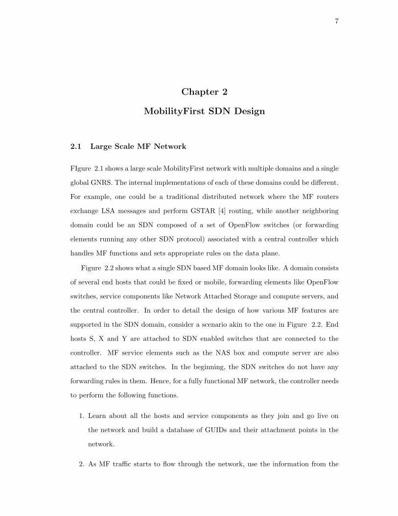
FIgure 2.1 shows a large scale MobilityFirst network with multiple domains and a single
global GNRS. The internal implementations of each of these domains could be different.
For example, one could be a traditional distributed network where the MF routers
exchange LSA messages and perform GSTAR [4] routing, while another neighboring
domain could be an SDN composed of a set of OpenFlow switches (or forwarding
elements running any other SDN protocol) associated with a central controller which
handles MF functions and sets appropriate rules on the data plane.
Figure 2.2 shows what a single SDN based MF domain looks like. A domain consists
of several end hosts that could be fixed or mobile, forwarding elements like OpenFlow
switches, service components like Network Attached Storage and compute servers, and
the central controller. In order to detail the design of how various MF features are
supported in the SDN domain, consider a scenario akin to the one in Figure 2.2. End
hosts S, X and Y are attached to SDN enabled switches that are connected to the
controller. MF service elements such as the NAS box and compute server are also
attached to the SDN switches. In the beginning, the SDN switches do not have any
forwarding rules in them. Hence, for a fully functional MF network, the controller needs
to perform the following functions.
1. Learn about all the hosts and service components as they join and go live on
the network and build a database of GUIDs and their attachment points in the
network.
2. As MF traffic starts to flow through the network, use the information from the

8
AS 1 - SDNCONTROLLER
OpenFlow Switch
OpenFlow Switch
OpenFlow Switch
AS 3 - Traditional Distributed Routers
MF Router
MF Router
MF Router
MF Router
AS 2 - SDNCONTROLLER
OpenFlow Switch
OpenFlow Switch
OpenFlow Switch
GNRS
Figure 2.1: Multiple MobilityFirst domains, each of them could be SDNs or traditionaldistributed networks
Controller
NAS BoxCompute Server
To: XService: Compute
To: Y
X Y
Service: ComputeFlow: Send to
Compute ServerDevice Y Missing
Flow: Send to Network Storage
Link to Y is down
Figure 2.2: High level design, controller functions, and flow rules

9
GUID ATTACHMENT POINT
1 SW 1, PORT 25
2 SW 1, PORT 30
3 SW 2, PORT 32
PKT TYPE - 3 SRC GUID - 3 SEQ NUM - 101
LINK PROBE PACKET
GUID DATABASE
Figure 2.3: Controller Building the GUID Database using Link Probe Messages
learning phase to set up appropriate forwarding rules on the switches to ensure
end to end data transfer.
3. Update the GUID database and the GNRS as and when mobile hosts migrate
from one attachment point to another or when they leave the network.
4. Send packets to the storage nodes when required, and manage the load if there
are multiple NAS boxes in the network.
5. Track the service IDs in MF chunks and route traffic through the compute servers
if required. As with the case of storage, manage the load on each compute server
if there is more than one in the network.
2.2 Data Flow in a MobilityFirst SDN
As hosts and switches come live in the MobilityFirst SDN, there is a series of steps
involved in enabling end to end data transfer between two hosts. This section details
the key functions involved.
2.2.1 GUID Learning
Every MF host that joins the network sends broadcast messages called Link Probes.
These link probes, which contain the GUID of the host are used by the controller to

10
associate each GUID with its attachment point in the network. This way the controller
builds a database of every GUID in the local network as shown in Figure 2.3.
In addition to hosts, the controller will also learn about the service components such
as NAS boxes and compute servers in the network. The service components can use a
simple discovery protocol to advertise their location and features to the controller.
As and when the controller learns about each host or service GUID in the network,
it will report it to the GNRS, which can be queried by the controllers of other MF
domains or by traditional MF routers.
2.2.2 Routing Decision
When MF data is transferred as chunks, only the first packet of each chunk has the
routing header which contains fields such as service ID, source GUID, destination GUID
etc. In the SDN set up, the first packet of each chunk is sent by the switch to the
controller. The controller looks at the header fields in the packet and uses its GUID
database to locate the attachment point of the destination device for this chunk. It
could also send out a GNRS request or decide to call upon storage or compute services
as will be described in subsequent sections. Once the routing decision is made, flow
rules have to be written on all switches along the path to ensure that subsequent packets
belonging to this chunk are forwarded by the switches to the destination host.
2.2.3 Flow Rules
When associated with a MobilityFirst SDN, every host that sends data on to the net-
work will tag the data packets with the Hop ID as the VLAN tag. Since the Hop ID
of all packets belonging to a chunk remains the same, all the packets in a chunk have
the same VLAN tag on them. This allows the controller to set up a flow rule which
matches packets based on the VLAN tag. Once the controller makes the forwarding
decision, it sends out flow rules to all switches along the path to the destination host,
matching packets based on the source MAC address and VLAN tag. Since the switches
now have a forwarding rule for this chunk, all subsequent packets belonging to this
chunk get forwarded to the destination host. A typical flow rule established to handle

11
Destination GUID - 4
No Entry in GUID TableQuery GNRS
Destination GUID - 2
Device not foundFlow Rule for Storage
Service: Compute
Flow Rule to Compute Server
Figure 2.4: Routing decisions made by the controller based on header fields
a MobilityFirst chunk is shown below.
ETHER TYPE = 0X27C0, VLAN ID = 101, SRC MAC = 2E:32:4D:54:32:4A =>
OUT PORT = 21
2.3 MobilityFirst Functions and Services
This section describes how MobilityFirst features, specifically mobility management, in-
network storage and in-network compute are implemented in an SDN. The MF chunk
handling and flow set up described in the previous sections serve as a foundation for
these advanced functions.
2.3.1 Mobility Management
As already mentioned in previous chapters, MF is designed around the principle of
seamless mobility management without placing any burden on the hosts or applications.
This is achieved by decoupling the host name from the host address, and keeping the
GNRS updated with the latest network address associated with each GUID (host name).
In an SDN, mobility within the domain of a controller can be handled without the need
for a GNRS and a GNRS query can be used when a host moves outside the domain.

12
X Y
Y
S1
S2
S3
Y - Previous Location
Y - Current Location
Switch NotificationsS3 - Device RemovedS2 - New Device Association
Controller ResponseUpdate Y in GUID-MAC TableSend New Flow rule to S2
NE
WFL
OW
_MO
D
Controller
Figure 2.5: Intra Domain Mobility and Corresponding Actions at the Controller
Intra Domain Mobility
We define intra domain mobility as the scenario when a host dissociates from one
attachment point and associates to another, and both attachment points are controlled
by the same SDN controller. This is depicted in Figure 2.5. The SDN architecture
is inherently suited to easily handle this scenario since the switches in the data plane
notify the controller of all device attachments and disconnections.
In Figure 2.5, consider the case when host Y moves from the switch S3 to the
switch S2. The switch S3 reports the dissociation even to the controller and the switch
S2 then reports the association event to the controller. In addition to this, the controller
also gets the link probes that host Y sends out after attaching to the middle switch.
The controller uses this information to update the attachment point for the GUID of
host Y in its local GUID database. If the network address of Y has now changed,
the controller will also update the GNRS about the change. Now that the controller’s
GUID database is up to date, it can install new forwarding rules on the switch to make
sure data destined to Y is delivered to its new location.

13
Y
S1
S2
S3
Y - Previous Location
Controller 1
Y
S1
S2
S3
Controller 2
Y - Current Location
GNRS
New Device Association YUpdate GNRS
New GUID - Y
GNRS Request-Response
GUID - YDevice not found for GUID YQuery GNRS for location
Destination GUID - Y
Figure 2.6: Inter Domain mobility and involvement of the GNRS
Inter Domain Mobility
We define inter domain mobility as the scenario when a host dissociates from an attach-
ment point under one SDN controller and associates with an attachment point under a
different SDN controller. Handling this type of mobility requires coordination between
the controllers of the two SDN domains. However, it is not necessary for them to di-
rectly exchange information between each other. All that the controller needs to do is
update the GNRS each time a new device joins the network and the controllers of other
domains can then query the GNRS periodically to find the network address of GUIDs
that are not a part of their local network.
In Figure 2.6, consider the case where host Y migrates from its existing attachment
point in the domain under controller 1 to an attachment point in the domain under
controller 2. In this case, controller 1 gets notified of the dissociation. Since it gets no
further information about host Y, it will query the GNRS for the current location of
the host with GUID Y. Controller 2, on receiving the link probe from Y, would have
updated the GNRS with Y’s current location. The GNRS will thus respond to controller
1 with the current network address of Y. Controller 1 will now set up forwarding rules
that will forward all further packets destined to Y to the new SDN domain that Y is
now a part of.

14
X
S1
S2
S3
Link to X down
PACKET_INDestination GUID: X
FLOW_MODNo link found to GUID XFLOW_MODs to S1 and S2Forward chunk to storage
Controller
NAS Box
Chunk to X
Figure 2.7: MF chunks get stored when the link to the destination is down
2.3.2 In-network Storage
As part of the GUID learning, the controller also learns about the NAS devices in the
network. These storage devices are used to temporarily store chunks if the link to the
destination host is down or if the destination GUID cannot be resolved to a routable
address by the GNRS. This class of delay tolerant traffic is indicated by a specific value
in the service ID field of the first packet of each chunk. When the controller receives
such a packet and finds that a destination host cannot be found at this point, it sends
the chunk to the storage device. This is done by setting up flow rules on the switches
that will forward all subsequent packets in the chunk to the storage device. However,
since the packets are now going to a different node than the one they were destined to,
the L2 destination address on the packets has to be rewritten to that of the storage
node. A flow rule performing this action would look like
ETHER TYPE = 0X27C0, VLAN ID = 101, SRC MAC = 2E:32:4D:54:32:4A =>
DATA LAYER DST = 2E:32:4D:3F:4A:74, OUT PORT = 18
Figure 2.7 represents the scenario described above. When the source sends a chunk
to GUID X, and the controller realizes that the device with GUID X is currently not
associated with the network, it sets flow rules on the switches S1 and S2 to set up a
path that forwards all packets in that chunk to the NAS box attached to switch S2.

15
X
S1
S2
S3
PACKET_INDestination GUID: X
Service ID: Compute Service
FLOW_MODCompute Service RequestedFLOW_MODs to S1, S2 and S3 to set flows from Source to Compute Server and from Compute Server to X
Controller
Chunk to XRequires Compute
ServiceCompute Server
Perform required computation and forward to X
Figure 2.8: MF chunks that require an in-network compute service are first forwardedto the Compute Server and then forwarded to the destination
When the device X shows up on the network, the controller learns of it through the
link probe broadcast and can then signal the NAS box to forward the chunk to host X.
2.3.3 In-network Compute Services
MobilityFirst also has in-network compute in order to enable enhanced network services.
When a stream of data requires a compute service in the network, it is specified by
using the service ID field. When the controller sees a chunk with this service ID field,
it immediately sets up a flow rule which sends subsequent data packets to the compute
server instead of the destination. Just like sending data to the storage router, this
requires a rewrite in the L2 destination field of the packets since they are being sent
to a node different from the the one the packets were destined to. Another set of flow
rules are used to set up the path from the compute server to the destination host. A
flow rule sending data to the compute server would look like
ETHER TYPE = 0X27C0, VLAN ID = 101, SRC MAC = 2E:32:4D:54:32:4A =>
DATA LAYER DST = 2E:32:4D:4E:54:6A, OUT PORT = 19

16
Figure 2.8 represents the scenario described above. When the source sends a chunk
with the service ID field indicating the requirement of a compute service, the controller,
sets up a flow rule on switches S1 and S2 to send packets of that chunk coming from
the source to the compute server. The controller also sets up another set of flow rules
on switches S2 and S3 to send data coming from the compute server to the destination
host X.

17
Chapter 3
OpenFlow Based Prototype
MobilityFirst features as detailed in the Chapter 2 have been implemented using the
OpenFlow protocol and the Floodlight controller. The following sections briefly sketch
the modular structure of the Floodlight controller and describe in detail the additional
modules built on top of Floodlight in order to handle MF functions.
3.1 Platform
Section 1.3 outlined the OpenFlow protocol and the main interactions between the
control plane and the data plane. The MobilityFirst SDN prototype works on any
network consisting of standard OpenFlow switches. Floodlight has been used as the
OpenFlow controller, and MobilityFirst modules have been built on top of it.
3.1.1 Floodlight
Floodlight is an Apache licensed, Java based OpenFlow controller that can work with
physical and virtual switches that speak the OpenFlow protocol. It takes care of the
communication with the OpenFlow firmware on the switch and also exposes APIs that
allow the user to set up flows on the switch in a proactive or a reactive manner. Flood-
light also provides a REST API that can be used to query the switch for statistics such
a traffic on each port, traffic per flow etc. The REST API can also be used to set
up static flows on the switch. However, as the name suggests, these flows can be set
up only with prior knowledge of the network or expected traffic and are hence known
as proactive flows. Floodlight also allows dynamic flow set up based on inspecting
PACKET IN messages. This is where its module loading system comes in.

18
3.1.2 Modular Structure
Functions that analyze the traffic and set up flows or manage the network dynamically
are organized as modules in Floodlight. Configuration files can be used to define which
modules are loaded during the controller’s start up, and the order in which OpenFlow
messages flow through the modules.
OpenFlow messages can be of several types, such as PACKET IN (sent by the
switch to the controller when it receives a packet that does not match any forwarding
rule), OFPT PORT STATUS (sent by the switch to the controller when the status of a
physical port of the switch changes) etc. Each of the modules in Floodlight can listen
for, or in other words, subscribe to a set of message types. Each time the controller
receives an OpenFlow message, it passes through all the modules that have subscribed
for that specific type of OpenFlow message. Based on the information contained in
these messages, the modules can perform computations and decide to add new entries
or remove entries from the flow tables on the switch.
In the case of implementing MobilityFirst functions, what the new modules need to
subscribe to are the PACKET IN messages which will bring in the link probes, CSYNs
and all other MF packets to these modules. They can then be handled appropriately
to perform the desired functions, as will be described in the next section.
3.1.3 Core Modules
Floodlight has a set of core modules that take care of communicating with the switch
and using updates such as OFPT PORT STATUS to maintain an up to date topology
of the network. These modules can be queried to access the information they have
accumulated. Following are some of the core modules that other MF modules will call
during their pipeline.
1. DeviceManager - Handles device added and device removed notifications from
the switch to maintain a database of devices in the network. The devices can be
queried by their L2 address.
2. Routing - Given any two switches in the network, the routing module uses

19
Floodlight CoreDevice Manager
Topology ManagerRouting
Static Flow Pusher..........
GUID Learning
GSTAR Routing
Device Added, Device
Removed etc.
PAC
KET
_IN
PAC
KET
_OU
TFL
OW
_MO
D
OpenFlow Switch
Storage Manager
Mob
ility
Firs
t Pac
ket C
lass
ifier
Compute Manager
Figure 3.1: Module Structure of Floodlight With MobilityFirst Functions
Dijkstra’s algorithm to return the shortest path between the two switches. Once
the destination device for a packet is found, this module is used to arrive at an
end to end path over which the flow has to be set up.
3.2 MobilityFirst Modules
Figure 3.1 shows the modular structure of Floodlight along with the MobilityFirst
modules. The MF modules interact among themselves and with Floodlight’s core mod-
ules to perform the desired functions. This section details the functions of each module
and the interaction between them.
3.2.1 MobilityFirst Packet Classifier
As a PACKET IN messages arrives at the controller, Floodlight’s core modules dissect
it and expose the header fields in the packet. However, the dissector looks for IP headers

20
and hence in order to perform MF functions, the first requirement is a dissector that
strips the PACKET IN message and exposes MF header fields to other modules that
require them.
The MF packet dissector inspects the ETHER TYPE field of the frame in the
PACKET IN message, and on finding an MF packet, extracts the various header fields
such as source GUID, destination GUID, hop ID, service ID etc. based on the packet
type. Other modules such as the GUID learning or routing module can then use these
fields to populate a table, initiate a flow set up etc.
3.2.2 GUID Learning and Routing
Once an MF packet is found inside a PACKET IN message, the packet type is checked,
and link probe packets are passed on to the learning module and CSYNs and data
packets are passed on to the routing module.
GUID Learning
The GUID learning module operates on link probes and as described in Section 2.1,
checks the source GUID in the link probe and adds it to the GUID table along with
the source MAC address. Once all the hosts in the network boot up, the controller has
a table of all GUIDs in the network and corresponding MAC addresses.
GSTSR Routing
The routing module handles MF PACKET IN messages that arise from data packets,
specifically the first data packet of each chunk. Once a data packet is identified, the
routing module uses the MF dissector to extract the destination GUID from the header.
It then looks up the GUID table built by the learning module for the MAC address
associated with this GUID. If a MAC address is found, then Floodlight’s core routing
module is used to find a route to the switch to which the destination host is attached to
and flow rules based on VLAN tags are set on all switches along the path as described
in the previous chapter.

21
Storage and Compute Managers
Additionally, the routing module also communicates with the storage and compute
managers handles the following special cases.
1. If the GUID table does not contain an entry for the destination GUID in the
packet, then the routing module can query the GNRS for a network address for
this GUID.
2. If the destination device with this MAC address cannot be found, then the routing
module sets up a flow to forward all packets belonging to this chunk to the a
storage device instead of the destination host. The storage manager holds data
about the current load on each storage node in the network and tells the routing
module which node the chunk should be sent to for storage.
3. If the service ID field in the packet indicates that an enhanced network service is
required, then the routing module sets up flows to forward the rest of the packets
belonging to this chunk to a compute server instead of the destination host. The
compute manager, which maintains data about the current load on each compute
server in the network, tells the routing module which compute server the chunk
has to be forwarded to.

22
Chapter 4
Evaluation and Validation
In order to evaluate the performance of the prototype, experiments were run on the
Orbit testbed in WINLAB. The performance can broadly be split into two categories;
performance of the control plane and that of the data plane. Analyzing the performance
of a MobilityFirst SDN prototype is especially interesting considering the fact that
depending on the chunk size, the fraction of packets that have to go through the control
plane could vary significantly. Even if the control plane delay is of an acceptable order,
the impact on the overall performance could be significant for small chunk sizes. Hence,
some of the data plane experiments focus of measuring the performance across a range
of chunk sizes.
4.1 Control Plane
Figure 4.1 depicts the various components contributing to the overall control plane
delay, which is the time incurred in setting up the flow for an MF chunk.
4.1.1 Flow Set up Delay
The overall flow set up time T is the sum of the three components T1 the transmission
delays, T2 the processing time at the controller and T3 the flow installation time on the
switch. Out of these, T1 and T3 depend on the hardware of the hosts and the switch
respectively. However, T2, the time taken by the controller to process a MobilityFirst
packet and send the FLOW MODs to the switch is of much more significance since it
is the component specific to a MobilityFirst implementation.
The CSYN message is used to initiate the transfer of a chunk of data in Mobility-
First. It is this packet that goes to the controller and initiates the flow set up for a

23
T2Process PACKET_IN
Set FLOW_MODSend PACKET_OUT
T1
T1
T1
T1Propagation Times
Switch Forwarding Delay
T3Flow Installation Time
Figure 4.1: Various components contributing to the overall flow set up delay
Table 4.1: Average CSYN RTT and average processing time at the controller
CSYN RTT 3.5ms 0.46ms
Controller Processing Time 114µs 32µs
chunk. Once the CSYN message has been acknowledged, the sender can initiate the
transfer of data packets belonging to the chunk. The delay in exchanging the CSYN
message is the overhead for the transfer of each chunk of data. The experiment to
measure this delay consisted of 10000 CSYN messages sent sequentially from a source,
each of them going to the controller and initiating a flow set up. Two different delays
were measured,
1. Total CSYN RTT - Figure 4.2 shows the path for this RTT, time stamps at the
source were used to measure the RTT for each CSYN.
2. Processing Time at Controller - Time stamps at the controller’s interface were
used to measure the time spent by each PACKET IN at the controller.
Table 4.1.1 shows the average time spent by the CSYN at the controller and the average
total RTT. It can be seen that the time spend processing at the controller is only a
very small fraction of the overall RTT.

24
SOURCECONTROLLER
PROCESS & SEND FLOWS
SWITCH
DESTIANTION
SWITCH
SWITCHSOURCE
Figure 4.2: Path taken by one CSYN round trip
1000 2000 3000 4000 5000 6000 7000 8000 9000 10000
200
400
600
800
1000
1200
1400
Packet arrival rate at the switch (Packets per second)
PA
CK
ET IN
arr
iva
l ra
te a
t th
e c
on
tro
ller
(Pa
cke
ts p
er
se
co
nd
)
Figure 4.3: Packet processing rate of the switch CPU
4.1.2 Data Plane to Control Plane Bandwitch at the Switch
The average processing time at the controller for an MF packet that requires a local
GUID look up is 114µs as explained above. In terms of the number of MF PACKET INs
that the controller can process per seconds, this translates to 8772 packets per second.
The other significant delay in packets that have to be sent to the controller is at the
switch. When a packet arrives at the switch, and does not match any of the flow rules
present in the switch’s flow tables, it has to be encapsulated with the OpenFlow header
and sent to the controller. This fetching and encapsulation is done by the switch’s
CPU, which, as pointed out in [20] is usually a cheap low capacity processor that
cannot handle heavy loads. However, for MF traffic to flow in a commodity OpenFlow
network, it is necessary that one packet in each chunk gets sent to the controller to look

25
up the local GUID database or the GNRS. This could potentially result in a heavy load
on the switch CPU. To understand the impact this could have on the performance of
the network, we studied the maximum throughput that the switch CPU in a Pronto
3290 could push to the controller in terms of packets per second. In this experiment,
a source sends MF CSYN packets to the switch, which in turn encapsulates them with
the OpenFlow header and sends them to the controller. The rate at which the source
loads the switch with MF packets is controlled, and the we look for the rate at which
PACKET INs arrive at the controller.
Figure 4.3 presents the PACKET IN arrival rate at the controller against the packet
arrival rate at the switch. The curve is linear till 1100 packets per second and then
flattens out irrespective of how much the arrival rate at the switch increases. We noticed
that the switch drops packets that that the CPU is unable to process, and hence for an
arrival rate of more than 1100 packets per second, the switch starts dropping packets
in the transfer from the data plane to the control plane.
4.2 Data Plane
The reference implementation of MF software router based on Click achieves a for-
warding throughput of around 260 Mbps for 1kB chunks and flattens out to around 400
Mbps at a chunk size of 1 MB. It then remains more or less constant for chunk sizes
ranging from 1 MB to 12 MB. The OpenFlow prototype shows a much higher variation
in performance with change in chunk size. For very small chunk sizes, the throughput
is very low of the order of few hundred kbps. However, this is understandable consid-
ering the fact that for chunk sizes of 1 kB, every data packet goes to the controller
and initiates a flow set up. As the chunk size increases, fewer packets have to go to
the controller, and hence the throughput starts to rise. For chunks that are forwarded
based on GUIDs, we see from Figure 4.4 that the throughput peaks at over 800 Mbps
for chunk sizes of 10 MB or more. Hence, for significantly large chunks, the OpenFlow
prototype can provide a better forwarding performance than software routers.

26
102
103
104
0
100
200
300
400
500
600
700
800
900
1000
Chunk Size in kilo bytes
Th
rou
gh
pu
t in
Mb
ps
NA forwarding
GUID forwarding
GNRS look up
Click Software Router
Figure 4.4: Chunk Size Vs. Throughput for various traffic classes
4.2.1 Single Flow Performance
As discussed before, the fraction of packets going to the controller and the time spent
at the controller can significantly affect the forwarding performance in the SDN set
up. In MobilityFirst, different traffic classes will have different processing times at the
controller, and sometime even a different fraction of packets going to the controller.
Hence the forwarding performance for each of these traffic classes is expected to be
different. Figure 4.4 compares the throughput achieved across a range of chunk sizes
for NA based forwarding, GUID based forwarding and chunks requiring GNRS lookup.
For forwarding based on network address, only the first packet of the first chunk
has to go to the controller. Since a flow can be set up on the switch based on the NA of
the destination, all packets belonging to all the subsequent chunks are forwarded by the
switch. As expected, this gives the maximum performance. GUID based forwarding
was discussed above and the increasing curve can be attributed to the decrease in the
fraction of the packets going to the controller. For traffic in which each chunk has to
undergo a GNRS lookup, the curve is similar to that of GUID based forwarding, but
the throughput values are much lower. This can be explained by the fact that while
the fraction of packets going to the controller is same in both the cases, the GNRS look
up incurs an additional delay at the controller which impacts the overall throughput.

27
1 2 3 4 5 6 7 8 9 10100
200
300
400
500
600
700
800
900Chunk Size Vs. Throughput For Mix of GUID and GNRS traffic
Chunk Size in mega bytes
Th
rou
gh
pu
t in
Mb
ps
No GNRS look up
20% GNRS look up
40% GNRS look up
60% GNRS look up
80% GNRS look up
Figure 4.5: Chunk Size Vs. Throughput for different ratios of traffic requiring GNRSlook up at the controller
4.2.2 Effect of Traffic Requiring GNRS Requests
When the first packet of an MF chunk arrives at the controller, it uses the information
gathered from its GUID learning process to identify the location of the destination
device on the network. However, if the destination host is not located in the same
SDN domain, then the controller does not have the attachment point in its GUID
database and has to query the GNRS for the current location of the destination GUID.
Querying the GNRS and awaiting for it’s response contributes to an additional delay in
the control plane. [3] presents experimental results on the average delay incurred in a
GNRS query, and we use values from [3] to simulate the GNRS delay at the controller
for every chunk that requires a look up.
Figure 4.5 shows the results of an experiment that was conducted to understand
the impact of the traffic that requires GNRS on the overall throughput. The curve
with maximum throughput is the one which has no traffic that requires GNRS look up,
every chunk is destined to a GUID that has an entry in the controller’s local GUID
database. From the rest of the curves, it can be seen that an increase in the number
of chunks that require a GNRS look up causes a hit on the throughput. For chunks
of size 10 MB (the maximum throughput in each curve), the throughput decreases by

28
Table 4.2: Average per flow throughput for various chunk sizes and number of flows
Chunk Size (MB) # of Flows Ave. Throughput Ave. throughput decrease per flow (Mbps)
11 493
432 4403 407
21 653
382 6123 577
41 729
182 7133 693
81 794
12.52 7843 769
101 818
7.52 8103 805
more than 300 Mbps for traffic in which 80% of the chunks require a GNRS look up
as compared to traffic that has no chunks that require a GNRS look up. However, in
this experiment, responses from the GNRS are not cached at the controller and two
consecutive chunks with the same destination GUID results in two GNRS look ups.
By maintaining a cache at the controller for storing the responses from the GNRS, the
delay can be reduced to an extent. However, caching GNRS responses introduces the
problem of having stale entries in the cache, and the timeout duration of the cached
values has to be decided carefully based on the network parameters and the frequency
of end host mobility in the network.
4.2.3 Effect of Multiple Flows
In a real world scenario, several hosts in the same SDN domain could be exchanging
data simultaneously. The existence of multiple flows at the same time loads the in
places such as the switch’s data plane, the switch’s CPU transferring packets from the
data plane to the controller, and the controller itself as it now has to analyze a larger
number of packets per second and set up a larger number of flows on the switches in
the network. As a result, the number of flow rules that the switches have to install also
29
increases and so does the time taken to match incoming data packets against the flow
rules (since most switches do a linear search on the flow table that holds the wildcarded
flow rules). Considering the OpenFlow prototype has been built to use wildcard flow
rules for MF traffic, and the inherent requirement that one packet per chunk has to
be sent to the controller for processing, it can be expected that multiple MF flows in
the SDN domain could result in a decrease in the average throughput because of the
factors mentioned above.
Table 4.2.3 presents the results from an experiment that was performed to measure
the impact of multiple MF flows on the average throughput. The last column in 4.2.3
is the key figure which represents the hit in throughput caused by the addition of each
MF flow. It can be seen that this is 43Mbps for flows with chunk size 1MB, which is a
decrease in throughput by 8.7%. As we increase the chunk size, the hit in throughput
decreases and this can be attributed to the decrease in the fraction of packets that are
sent to the controller. For example, for 10MB chunks, the decrease in throughput per
flow is only 7.5Mbps and this is just a 0.91% when compared to the baseline single
flow throughput of 818Mbps. The results thus show that a single OpenFlow switch can
handle multiple MF flows as long as the chunk size is of the order of several MB. While
this is feasible for traffic on Ethernet, it might not be possible over a wireless link and
hence multiple MF flows could result in a significant decrease in throughput in such a
scenario.
4.3 Performance Bottlenecks
Clearly the load on the controller for MobilityFirst traffic is much higher than the load
for IP traffic because one packet per chunk has to go to the controller to initiate the
flow set up. Hence for small chunks that create a lot of control traffic, performance
bottlenecks can be expected in some parts of the network. In this section, potential
locations for the bottleneck are considered and analyzed.

30
4.3.1 Controller
Results from the previous section showed that the time taken by the controller to process
an MF PACKET IN is 114µs on average. Ideally, this puts the processing throughput
of the controller at over 8700 PACKET INs per second. While this is a significantly
large number for mega byte sized chunks, some bottlenecks might arise when several
switches send concurrent PACKET INs to the controller.
4.3.2 Switch CPU
Every time the switch gets a packet that does not match any of the flows in its tables,
it has to encapsulate the packet with the OpenFlow header and then forward it to the
controller. This process takes place in the switch’s CPU which is usually not powerful
enough to handle heavy loads. As shown earlier in this chapter, on a Pronto 3290 the
upper limit on the rate at which the switch could send packets to the controller was
found to be 1100 packets per second. When several hosts connected to the same switch
start sending data as small chunks, this could become a very severe bottleneck in the
control plane as pointed out in [20]. The authors in [20] also come up with a solution
to this problem by adding another more powerful CPU to the switch and using that to
process packets that need to be transferred to the control plane. Such a solution could
be even more relevant in an SDN handling MF traffic considering the inherently larger
amount of traffic in the control plane for MF as compared to IP.
4.3.3 Switch Flow Tables
Every MobilityFirst flow is a wildcard flow rule that matches on a specific set of header
fields. The number of wildcard rules that most switches support is of the order of a few
thousands. Similar to the switch CPU, the flow tables could become full if too many
hosts on the same switch initiate a large number of flows by sending data as small
chunks, and hence the flow table size is also a potential bottleneck for a MobilityFirst
network.

31
Chapter 5
Conclusions and Future Work
The MobilityFirst protocol stack can be implemented on an SDN platform and our
design shows that all key features such as hybrid name-address forwarding, storage
for delay tolerant traffic and in-network compute services can be implemented. The
OpenFlow based prototype built on top of the Floodlight controller serves as a ref-
erence implementation for key features such as GUID based forwarding and enabling
in-network storage. The modular structure of the controller allows us to easily intro-
duce new network functions and services by extending the controller with new modules
that handle the required services.
Performance evaluations show that for chunk sizes that are in the order of mega
bytes, the forwarding throughput is much higher than that of software routers, and
approaches line rate for traffic that can be forwarded simply based on GUIDs. Chunks
that require a GNRS look up reduce the throughput as they incur an additional delay for
the communication between the controller and the GNRS. This could get compounded
when considering the fact that there could be multiple flows in the same SDN domain,
all having a significant fraction of chunks that require a GNRS look up. However, for
traffic within the SDN domain, multiple flows can be supported with minimal decrease
in throughput.
Some of the limitations include
1. Low throughput for small chunks.
2. Heavy load on the switch CPU when a large fraction of packets have to be sent
to the controller.
3. Potential shortage of flow tables for large networks that continuously exchange

32
data as small chunks.
Limitation 1 can be addressed as SDN switches evolve and start supporting flows
based on arbitrary bytes in the header instead of just IP header fields. Solutions for
the switch CPU bottleneck already exist as pointed out in [20]. As SDN switches start
supporting flows based on arbitrary header fields, wildcard flows can be avoided thereby
giving us a much larger flow table to use.
For future work, the OpenFlow prototype can be extended in a few ways, the first of
which is interfacing the controller with the GNRS. Future work also includes designing
and building a protocol for the controller to manage the storage and compute elements
in the network. If the modular structure of the controller functions are maintained,
then the existing prototype can be naturally extended as new network services are
introduced into MobilityFirst.
33
References
[1] I. Seskar, K. Nagaraja, S. Nelson, and D. Raychaudhuri, “Mobilityfirst futureinternet architecture project,” in ACM AINTec 2011. ACM, 2011, p. 5.
[2] A. Venkataramani, A. Sharma, X. Tie, H. Uppal, D. Westbrook, J. Kurose, andD. Raychaudhuri, “Design requirements of a global name service for a mobility-centric, trustworthy internetwork,” in Proceedings of the 2013 Fifth InternationalConference on Communication Systems and Networks (COMSNETS), 2013.
[3] T. Vu, A. Baid, Y. Zhang, D. Nguyen, J. Fukuyama, R. Martin, and D. Raychaud-huri, “Dmap: A shared hosting scheme for dynamic identier to locator mappingsin the global internet,” in Proceedings of IEEE ICDCS 2012, 2012.
[4] S. Nelson, G. Bhanage, and D. Raychaudhuri, “Gstar: Generalized storage-awarerouting for mobilityfirst in the future mobile internet,” in Proceedings of the 6thInternational Workshop on Mobility in the Evolving Internet Architecture (Mo-biArch), 2011.
[5] N. Somani, A. Chanda, S. Nelson, and D. Raychaudhuri, “Storage aware routingprotocol for robust and efficient services in the future mobile internet,” in Proc.IEEE International Communications Conference, FutureNet Workshop, 2012.
[6] Y. Chen, A. Li, and X. Yang, “Packet cloud: Hosting in-network services in acloud-like environment,” Duke CS-TR-2011-10, 2011.
[7] N. McKeown, T. Anderson, H. Balakrishnan, G. Parulkar, L. Peterson, J. Rexford,S. Shenker, and J. Turner, “Openflow: Enabling innovation in campus networks,”2008.
[8] “Open Networking Foundation (ONF),” https://www.opennetworking.org/.
[9] “Openflow switch specification, version 1.0.0 (wire protocol 0x01),”http://www.openflow.org/documents/openflow-spec-v1.0.0.pdf, 2009.
[10] “Floodlight, an apache licensed openflow controller,”https://www.projectfloodlight.org/.
[11] M. Othman and K. Okamura, “Design and implementation of application basedrouting using openflow,” in Proceedings of the 5th International Conference onFuture Internet Technologies (CFI ’10), 2010.
[12] H. Egilmez, S. Dane, K. Bagci, and A. Tekalp, “Openqos: An openflow controllerdesign for multimedia delivery with end-to-end quality of service over software-defined networks,” in Signal and Information Processing Association Annual Sum-mit and Conference (APSIPA ASC), 2012 Asia-Pacific, 2012.

34
[13] F. de Olivera Silva, J. de Souza Pereira, P. Rosa, and S. Kofuji, “Enabling futureinternet architecture research and experimentation by using software defined net-working,” in 2012 European Workshop on Software Defined Networking (EWSDN),2012.
[14] A. Bianco, R. Birke, L. Giraudo, and M. Palacin, “Openflow switching: Data planeperformance,” in 2010 IEEE International Conference on Communications (ICC),2010.
[15] A. Tootoonchian, S. Gorbunov, Y. Ganjali, M. Casado, and R. Sherwood, “Oncontroller performance in software-dened networks,” in 2nd USENIX Workshopon Hot Topics in Management of Internet, Cloud, and Enterprise Networks andServices (Hot-ICE), 2012.
[16] “cbench - a benchmarking tool for openflow controllers,”http://docs.projectfloodlight.org/display/floodlightcontroller/Cbench+(New).
[17] M. Jarschel, F. Lehrieder, Z. Magyari, and R. Pries, “A flexible openflow-controller benchmark,” in 2012 European Workshop on Software Defined Network-ing (EWSDN), 2012.
[18] M. Jarschel, S. Oechsner, D. Schlosser, R. Pries, S. Goll, and P. Tran-Gia, “Mod-eling and performance evaluation of an openflow architecture,” in 2011 23rd In-ternational Teletraffic Congress (ITC), 2011.
[19] M. Fernandez, “Comparing openflow controller paradigms scalability: Reactiveand proactive,” in 2013 IEEE 27th International Conference on Advanced Infor-mation Networking and Applications (AINA), 2013.
[20] R. Narayanan, S. Kotha, G. Lin, A. Khan, S. Rizvi, W. Javed, H. Khan, andS. Khayam, “Macroflows and microflows: Enabling rapid network innovationthrough a split sdn data plane,” in 2012 European Workshop on Software DefinedNetworking (EWSDN), 2012.