Embed Size (px)
Citation preview
MASTER THESIS
GLOBAL SYSTEMS DESIGN
Implementation of 3D printing technology in flexographic packaging printing
Dimitrios Tsakos
Supervised by Associate Professor Lazaros Nalpantidis
Title: Implementation of 3D printing technology in flexographic packaging printing
Semester:
4th
Project type:
Master Thesis
Project Period:
01/09/2017 to 04/01/2018
ECTS:
30
Supervisor:
Lazaros Nalpantidis
Project Author: Dimitrios Tsakos (Student number 20151775)
Table of contents TABLE OF CONTENTS ----------------------------------------------------------------------------------------------------------------------- 2
PREFACE --------------------------------------------------------------------------------------------------------------------------------------- 3
ACKNOWLEDGMENTS --------------------------------------------------------------------------------------------------------------------- 3
ABBREVIATIONS ----------------------------------------------------------------------------------------------------------------------------- 4
INTRODUCTION ------------------------------------------------------------------------------------------------------------------------------ 5
PROBLEM FORMULATION ------------------------------------------------------------------------------------------------------------------- 6 RESEARCH QUESTIONS ---------------------------------------------------------------------------------------------------------------------- 6 LIMITATIONS DELIMITATIONS --------------------------------------------------------------------------------------------------------------- 6 METHOD ------------------------------------------------------------------------------------------------------------------------------------- 8
THEORETICAL BACKGROUND ------------------------------------------------------------------------------------------------------------ 9
PRINTING HISTORY -------------------------------------------------------------------------------------------------------------------------- 9 FLEXOGRAPHIC PRINTING PLATES -------------------------------------------------------------------------------------------------------- 10 POLYMERS --------------------------------------------------------------------------------------------------------------------------------- 11 BRIEF HISTORY OF ADDITIVE MANUFACTURING AND 3D PRINTING ------------------------------------------------------------------ 12
CASE STUDY --------------------------------------------------------------------------------------------------------------------------------- 14
COMPANY INTRODUCTION ---------------------------------------------------------------------------------------------------------------- 14 MACHINES DESCRIPTION ------------------------------------------------------------------------------------------------------------------ 15 FLEXOGRAPHIC PRINTING PLATES -------------------------------------------------------------------------------------------------------- 18 PRODUCTION FLOW ----------------------------------------------------------------------------------------------------------------------- 21
EXPERIMENT-------------------------------------------------------------------------------------------------------------------------------- 24
RECREUS FILAFLEX RANDOM SAMPLING ------------------------------------------------------------------------------------------------- 30 POLYMAKER’S POLYFLEX RANDOM SAMPLING ------------------------------------------------------------------------------------------ 32 EXPERIMENT’S PIVOT TABLES ------------------------------------------------------------------------------------------------------------ 33 EXPERIMENT EVALUATION ---------------------------------------------------------------------------------------------------------------- 34
ECONOMIC FEASIBILITY ----------------------------------------------------------------------------------------------------------------- 36
HYPOTHESIS -------------------------------------------------------------------------------------------------------------------------------- 37
CONCLUSION ------------------------------------------------------------------------------------------------------------------------------- 38
REFERENCES -------------------------------------------------------------------------------------------------------------------------------- 39
TABLE OF FIGURES ------------------------------------------------------------------------------------------------------------------------ 41
TABLE OF TABLES-------------------------------------------------------------------------------------------------------------------------- 42
APPENDICES -------------------------------------------------------------------------------------------------------------------------------- 43
APPENDIX A, CHARACTERISTICS OF 3D PRINTING MATERIALS ------------------------------------------------------------------------- 43 APPENDIX B, FINAL PRINTED PAPER BAGS ----------------------------------------------------------------------------------------------- 45 RECREUS FILAFLEX’S IMPRINTS ----------------------------------------------------------------------------------------------------------- 45 POLYMAKER POLYFLEX’S IMPRINTS ------------------------------------------------------------------------------------------------------ 48 APPENDIX C, EXPERIMENT’S DETAILED DATA -------------------------------------------------------------------------------------------- 52 APPENDIX D, PHOTOS AND TABLES ------------------------------------------------------------------------------------------------------ 55 APPENDIX E, PROJECT’S GANTT CHART -------------------------------------------------------------------------------------------------- 63
Preface The concept for this project, was born during a conversation I had with a good friend of mine who owns a small printing paper factory in Chios island, back in Greece. Many times, in the past we have been discussing about his business and about the hard work in his factory. It is quite challenging for a small company to run its business from the very start with the orders, facilities, labour, machinery, packaging and even delivering the final products with its very own capacity. It doesn’t seem easy at all and for sure this small place, has potentials for improving in many areas of its operation. We really have had interesting talks regarding the actual printing process, which I feel is quite impressive. When I got explained the basic philosophy of how the machine works, something was telling me that I could do something in there, to learn more and perhaps I could come up with some idea for my good friend Kostas. We talked about the printing plates that he uses for his production. One of his main concerns was the cost of it and that there wasn't any possible way of modifying it, without damaging the prototype. He did once try to modify the printing plate (I figured out the name after I started working on this) in order to accommodate a customer’s request on adding a Christmas decoration on it. A bakery logo for December only. He kind of ruined the plastic mould with the logo. He did manage to satisfy his customer, but now he had a ruin plastic negative of the logo, into pieces. That part costed approx. 250 euro, and its replacement was expensive. Something was blinking in my mind, but without giving that much thought until when I discussed the matter with Professor Lazaros Nalpantidis and he proposed to investigate the possibility of using a three-dimensional printer (3DP) for that matter. A master thesis, presented here in Aalborg University, had previously investigated the 3D printed injection mould tools and based on that case study, significant results there were presented. It was very interesting to see how this excellent work, proceeded throughout the pages, experimenting with the 3D printing technology, proving that there are many benefits of its application and a definite need for attention in manufacturing processes, more than in the prototyping phases that it was aimed for, in the early years when this technology was born. I couldn’t have had a better opportunity than that, to use what I have learned during the period of the master’s programme had started. In fact, I have had courses and projects with the use of the 3D printing technology as a focus item, and I could see now a possibility of combining this experience with other topics that the university offered me throughout the semesters. That would be an excellent self-test, for applying my knowledge with a real-time business problem. I could apply the MSc tools to, identify the system, its characteristics and problems, redesign it, and evaluate the final results, having gained an overall look of this specific system.
Acknowledgments Firstly, I would like to thank my supervisor Lazaros Nalpantidis from Aalborg University. This work, wouldn’t have come to life without his guidance. I would also like to thank my dear good friend Konstantinos Evgenikos, the owner of Hartopolis paper printing factory, which offered all his knowledge and of course the facilities and equipment for this project. He was always busy with work and family, but he did everything he could to help me fulfil this project. I would also like to thank 3DHub and Kostis, the 3D printing expert who helped me out with the items we have created in his lab, it wouldn’t be possible without his help. I shouldn’t forget my family back in Chios, which they have had the kid again in house, being spoilt, after many years living abroad. Closing I would really like to thank my very good friends, Allan, Graca, Inga, Jesper, Karsten, Katerina, Maria, Michael and Stefanos, that they were picking up the phone once in a while, to send me good energy and pull me back into the work mode. Their support was what I really needed, and I feel they have had a share of this work.
Abbreviations AM additive manufacturing
ABS acrylonitrile butadiene styrene
CAD computer aided design
FAB LAB fabrication laboratory
FDM fused deposition modelling
LOM laminated object manufacturing
R2R roll to roll
RP rapid prototyping
SGC solid ground curing
SL stereolithography
SLA stereolithography apparatus
SLS selective laser sintering
SME Small and medium-sized enterprises
STL standard tessellation language
TP thermoplastics
TS thermosets
TPC thermoplastic co-polyester
UV ultraviolet electromagnetic radiation
3DP three-dimensional printing
3DP flexo-plate three-dimensional flexographic printing plate
Introduction Since the industrial revolution had started for more than 250 years ago, the use of machines has been
the major part of this breakaway. The hand labour was replaced by the industrialization while the
constant technological development, came side by side along the way, together with terms, such as,
time, money, efficiency, effectiveness, quality, customer satisfaction.
One of the most distinguished technologies that became a major part of worlds daily lives was printing.
Printing in nowadays is everywhere, from books to magazines, street signs, to food packaging, from a
tiny wrapping paper to a large scaled advert sign on top of a building, a truck or an aircraft. Obviously,
this industry has created products and services that our societies are using and counting on a constant
basis. More particularly, flexography is a printing technique which finds applications mainly in the
packaging printing industry, including food packaging, using thin substrates from materials, such as
paper, cellophane and many more. The printing press that is used in this industry, is a complex machine
which often combines more processes than printing, such us folding, packing etc, to produce the final
products.
European commission reports, that the 99% of the European enterprises, labelled as micro, small, or
medium sized, are dominating the European market. The SME’s that are commonly known, are
enterprises having less than 250 persons to work for them [1]. The 1% of the big enterprisers, seems to
have more people, money and opportunities to invest to new technologies, without any significant
delays or issues in their function. But what about the smaller ones? Even though they dominate the
market, the budget usually doesn’t give the chance for updating the equipment, hiring more personnel,
or introducing their businesses to new technologies, able to boost their performance. On the other
hand, there are companies that have even less than 10 employees which directly labelled as micro
enterprises. Those companies, also need to find ways to improve their productions, cut costs and
improve the technologies they currently use.
This project was accomplished in collaboration with Hartopolis, a paper printing factory with 3
employees. The expensive raw materials comparing with the prices that bigger sized companies can
get, the old machines and an increasing order demand, which is positive but challenging, because of
the special requests for customization needs. Due to seasonal changes customers, requests on small
adjustments on their logos, are increased. Logos modified during Christmas, Easter, winter or summer,
would make more attractive and competitive the company’s production. This seasonal modification
though, is not affordable, since the current plate making is expensive and time consuming due to the
external partner’s production flow. All those assets together with the external partners, added to the
puzzle, the company is trying to survive and think ways for its efficient and as competitive as possible
performance. There is not budget for innovative big plans, but still there is knowledge, technologies
and will power, that can always make a difference.
There is a main part of the printing presses, called flexographic printing plate, which is responsible for
the imprints on packaging. That could be interesting to be re-designed and produced with the use of
3D printing technology, which currently is blooming. Since 3D printing technology is getting more
affordable every year, and constantly evolving and there is a customer demand in customizations of
their products, it would worth to investigate this matter and try to find out how this idea could come
to life, and merge the two technologies together and see what the outcome could have been.
Therefor this project will test the possibility of re-designing and creating with a new manufacturing
method the flexographic printing plates, replacing the dominant current plate making technique and
examine the advantages and disadvantages from the attempt.
Problem formulation In this project will be investigated the possibility of replacing the current printing plates manufacturing technology, by using three-dimensional printers (3DP), as well as if there are to be found other materials which can replace the ones that are currently used. That would allow Hartopolis not to rely on external suppliers for the printing plates, to have frequent design changes and to reduce production costs.
Research questions
The main research questions that will be answered are:
o How does the current process flow with the use of the flexographic plate?
o Is the use of a 3D printed printing plate, technically and economically feasible?
o How realistic is the implementation of a new technology?
Limitations delimitations Firstly, Hartopolis provided access to the factory to observe and understand the processes involved in
typical production day. It should be noted, that printing days, are only based on incoming orders. The
order’s pace, is based on the season. The current time that this project took place was in a low
production season. That means that the opportunities of observation of the actual printing day were
only few.
That didn’t create any negative effect in the current work, since the aim was on the printing plates and
their replacement from the new ones. That gave the opportunity to test the 3D printed prototypes
when the machines had a “day off”.
Secondly, regarding the printing experiment, it should have been taken into consideration that it wasn’t
economically feasible to run the machines for long time, due to paper, electricity, ink and time costs.
The experiment ideally could have run for a certain time of the day but the practicalities, gave the
opportunity to run it for each of three-dimensional printed flexographic plate (3DP flexo-plates) for a
sort cycle. A longer cycle could have put in a more realistic test the material’s strength, durability under
pressure and a better understanding in its aging process, during the printing process.
Another fact was that there wasn’t a direct access to a 3D printer or any fab lab in the island. The only
alternatives, were 3D printing companies which they were found online, located in Athens. That means
that more tests, printing attempts, material selection and general experimentation could have been
accomplished, but that narrowed down the experiment’s options. It was decided for the 3DP part, to
be taken care of an external partner, which in this case was a company called 3Dhub. The company
choice was made based on its very positive review, large varieties with 3DP materials, different kind of
printers and quite good experience, since they are in the market more than two years, having great
success. The distance also had to be taken into consideration and the difficulty that was faced regarding
ordering, producing and delivering the items needed. Therefor lack of direct access to a lab limited the
efforts and results of this work.
It should be also noticed, that processing methods to finishing the products, will not be investigated.
Nevertheless, the experienced gained during the Master’s program back at the university’s fab lab, by
having worked closely with 3D printers and CAD programs, redesigning and producing prototypes, as
well as a visit to a 3D printing company, provided valuable experience over that matter.
It should be also noticed that topics such as marketing, and the use of other additive manufacturing
and not only technologies weren’t chosen to focus on. The economic feasibility of this work, was
decided to present the direct cost only, (paper, ink, platemaking) and no 3D printer prices and the
general cost of running the business, such as electricity, labour, taxation etc., have been considered.
The logo chosen to be the focus for the project, were initially, the Aalborg’s university logo which is
relatively simple and a logo that Hartopolis uses for one of their active customers. Nevertheless, the
prices for printing plates in the actual size (an average plate is 12,5 cm x 40cm) that the company uses
for its production, would have been proved costly, even before the experiment had started. The choice
of a smaller and simper logo, was thought as a good way to start, test and evaluate the idea, before
moving further on bigger and more complex printing plates. For the same reason, it was decided the
use for one colour only, meaning only one printing plate (if an image requires more colours, each colour
should have its assigned printing plate).
Another tool used within this work, is the SIPOC (suppliers, inputs, process, output, customers) high
level process map. This tool is commonly used in Lean Six sigma, which combines different tools for
process improvement. This work will not utilize this technique, but it was decided this specific flow chart
to be used, to create an overview of the Hartopolis as a system and by analysing the interconnection in
between the different processes.
Method
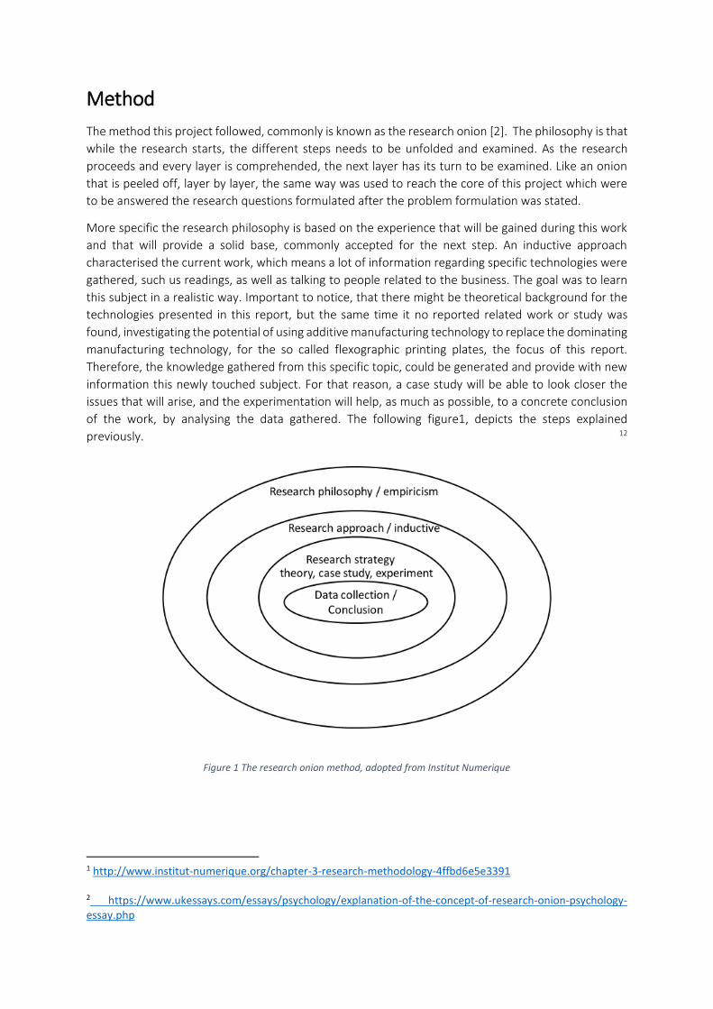
The method this project followed, commonly is known as the research onion [2]. The philosophy is that
while the research starts, the different steps needs to be unfolded and examined. As the research
proceeds and every layer is comprehended, the next layer has its turn to be examined. Like an onion
that is peeled off, layer by layer, the same way was used to reach the core of this project which were
to be answered the research questions formulated after the problem formulation was stated.
More specific the research philosophy is based on the experience that will be gained during this work
and that will provide a solid base, commonly accepted for the next step. An inductive approach
characterised the current work, which means a lot of information regarding specific technologies were
gathered, such us readings, as well as talking to people related to the business. The goal was to learn
this subject in a realistic way. Important to notice, that there might be theoretical background for the
technologies presented in this report, but the same time it no reported related work or study was
found, investigating the potential of using additive manufacturing technology to replace the dominating
manufacturing technology, for the so called flexographic printing plates, the focus of this report.
Therefore, the knowledge gathered from this specific topic, could be generated and provide with new
information this newly touched subject. For that reason, a case study will be able to look closer the
issues that will arise, and the experimentation will help, as much as possible, to a concrete conclusion
of the work, by analysing the data gathered. The following figure1, depicts the steps explained
previously. 12
Figure 1 The research onion method, adopted from Institut Numerique
1 http://www.institut-numerique.org/chapter-3-research-methodology-4ffbd6e5e3391 2 https://www.ukessays.com/essays/psychology/explanation-of-the-concept-of-research-onion-psychology-essay.php
Theoretical background
Printing history Johannes Gutenberg back in 6th November in Mainz Germany 1445, introduced the world to his
breaking through invention, the letter press printing techniques. His innovation, the moving type
printing machine, produced the first book ever printed in Europe, the so called “Forty-Two-Line” Bible.
Johannes Gutenberg’s name was recognized as the father of the letter printing. The next 400 years
whole Europe used his invention as a standard printing type process. [3] The letterpress, known also as
relief printing, basically uses metallic parts, such as (letters, lines, punctuation, in different fonts etc)
that are raised in such a position within the printing surface, while ink supplied to those raised parts.
The pressure applied to the specific area of the raised surface, results to the printed paper on demand.
Introduction to flexography
Flexography is an improved letterpress technique with the only difference that the printing plates used
on cylinder for that case, are constructed by flexible or soft materials, such us rubber or plastic, instead
of the hard metal printing plates that letter press uses. Important to notice, that those printing
processes are distinguished as, roll to roll (R2R) manufacturing processes which are allowing high
printing speeds in mass production which is an advantage.
The ability to print on any flexible and underlying layer or substrate as it commonly called, such as
paper, cellophane, plastics, even microelectronics, makes the flexographic printing very popular,
especially for food packaging and product labelling. This kind of printers operates in a highly efficient
and cost-effective manner. Depending on the machine, the printing rate can reach up to 400
meter/minute. That is a remarkable speed comparing with digital printing or lithographic presses. The
technology finds applications commonly, in food packaging, which demands high levels of health and
safety standards. Important to notice that the broad ink diversity (low viscosity), such as Water based,
Solvents and Ultraviolet (UV) makes flexography more appealing to different customers. [4]
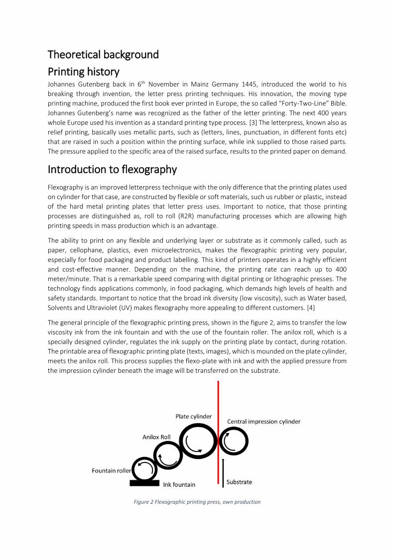
The general principle of the flexographic printing press, shown in the figure 2, aims to transfer the low
viscosity ink from the ink fountain and with the use of the fountain roller. The anilox roll, which is a
specially designed cylinder, regulates the ink supply on the printing plate by contact, during rotation.
The printable area of flexographic printing plate (texts, images), which is mounded on the plate cylinder,
meets the anilox roll. This process supplies the flexo-plate with ink and with the applied pressure from
the impression cylinder beneath the image will be transferred on the substrate.
Figure 2 Flexographic printing press, own production
Flexographic printing plates A large variety of flexographic printers, with Europe and USA leading in this manufacturing production
are commonly found in the market. The platemaking process is the most important part. The
flexographic printing plate as it is called commonly named as flexo-plate, which is a plain flat flexible
base where the text and images are raised off and kept grouped together, resulting on the negative of
the imprint to be printed. Depending on the number of colours required for the final image, separate
plates needs to be produced, corresponding to the colour number, resulting in a two, or up to five
coloured images.
Three main platemaking manufacturing processes can be distinguished, throughout the printing
history:
o Metallic plate etching / rubber plates:
Initially, an engraved negative of the print image is created on a plate made of metal zinc or
magnesium. The emerged image will be visible on the plate after, a thorough wash in an acid bath.
As a following step, a plastic mould is produced, shaping the flexible thermoplastic polymers, to the
final printing plates. This method is not used nowadays, because it tends to be rather time-
consuming and expensive.
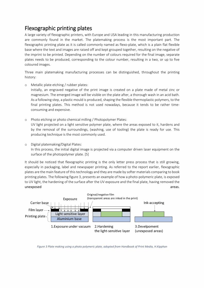
o Photo etching or photo chemical milling / Photopolymer Plates:
UV light projected on a light sensitive polymer plate, where the areas exposed to it, hardens and
by the removal of the surroundings, (washing, use of tooling) the plate is ready for use. This
producing technique is the most commonly used.
o Digital platemaking/Digital Plates:
In this process, the initial digital image is projected via a computer driven laser equipment on the
surface of the photopolymer plate. [5]
It should be noticed that flexographic printing is the only letter press process that is still growing,
especially in packaging, label and newspaper printing. As referred to the report earlier, flexographic
plates are the main feature of this technology and they are made by softer materials comparing to book
printing plates. The following figure 3, presents an example of how a photo-polymeric plate, is exposed
to UV light, the hardening of the surface after the UV exposure and the final plate, having removed the
unexposed areas.
Figure 3 Plate making using a photo polymeric plate, adopted from Handbook of Print Media, H.Kipphan
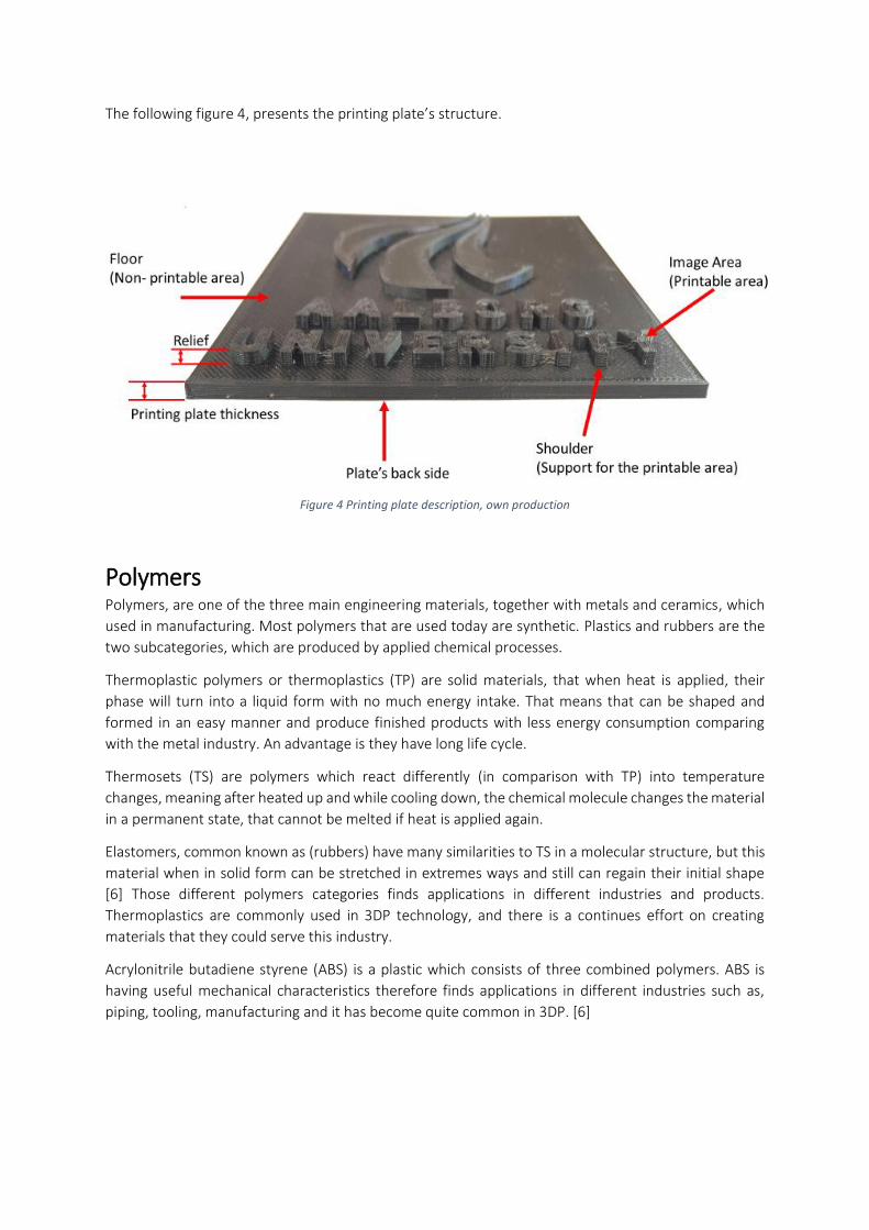
The following figure 4, presents the printing plate’s structure.
Figure 4 Printing plate description, own production
Polymers Polymers, are one of the three main engineering materials, together with metals and ceramics, which
used in manufacturing. Most polymers that are used today are synthetic. Plastics and rubbers are the
two subcategories, which are produced by applied chemical processes.
Thermoplastic polymers or thermoplastics (TP) are solid materials, that when heat is applied, their
phase will turn into a liquid form with no much energy intake. That means that can be shaped and
formed in an easy manner and produce finished products with less energy consumption comparing
with the metal industry. An advantage is they have long life cycle.
Thermosets (TS) are polymers which react differently (in comparison with TP) into temperature
changes, meaning after heated up and while cooling down, the chemical molecule changes the material
in a permanent state, that cannot be melted if heat is applied again.
Elastomers, common known as (rubbers) have many similarities to TS in a molecular structure, but this
material when in solid form can be stretched in extremes ways and still can regain their initial shape
[6] Those different polymers categories finds applications in different industries and products.
Thermoplastics are commonly used in 3DP technology, and there is a continues effort on creating
materials that they could serve this industry.
Acrylonitrile butadiene styrene (ABS) is a plastic which consists of three combined polymers. ABS is
having useful mechanical characteristics therefore finds applications in different industries such as,
piping, tooling, manufacturing and it has become quite common in 3DP. [6]
The market has quite a few companies producing flexographic plates, with different names each
company such as Cyrel from Dupont, Nylonflex from Flintgroup and Flexcel from Kodak, but following
the same manufacturing plate making principle. These manufacturers having a large variety of products
and equipment related to flexographic printing [7] [8] [9] [10]
Nevertheless, Cyrel is the most popular method in flexography, but that comes as well with a high price. Especially, when it is about small companies that the production, follows a low pace. An option of replacing it with another printing making method, such the 3DP which is examined in the current work, would seem appealing for Hartopolis.
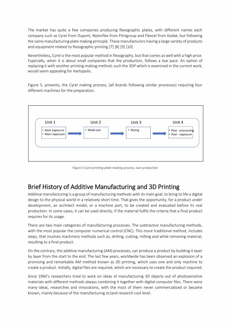
Figure 5, presents, the Cyrel making process, (all brands following similar processes) requiring four
different machines for the preparation.
Figure 5 Cyrel printing plate making process, own production
Brief History of Additive Manufacturing and 3D Printing Additive manufacturing is a group of manufacturing methods with its main goal, to bring to life a digital
design to the physical world in a relatively short time. That gives the opportunity, for a product under
development, an architect model, or a machine part, to be created and evaluated before its real
production. In some cases, it can be used directly, if the material fulfils the criteria that a final product
requires for its usage.
There are two main categories of manufacturing processes. The subtractive manufacturing methods,
with the most popular the computer numerical control (CNC). This more traditional method, includes
steps, that involves machinery methods such as, drilling, cutting, milling and while removing material,
resulting to a final product.
On the contrary, the additive manufacturing (AM) processes, can produce a product by building it layer
by layer from the start to the end. The last few years, worldwide has been observed an explosion of a
promising and remarkable AM method known as 3D printing, which uses one and only machine to
create a product. Initially, digital files are required, which are necessary to create the product required.
Since 1960’s researchers tried to work on ideas of manufacturing 3D objects out of photosensitive
materials with different methods always combining it together with digital computer files. There were
many ideas, researches and innovations, with the most of them never commercialized or became
known, mainly because of the manufacturing or/and research cost level.
Unit 1 Unit 2 Unit 3 Unit 4
All started back in 1967, when a Danish researcher named Wyn K. Swainson and his partners, had the
idea of creating a 3-Dimensional object by using a laser beam that could change after its application,
the physical characteristics of a photosensitive material. The patent was granted in 1981 but it didn’t
go as expected until it died out few years later. [11]
Charles W. Hull the founder of 3Dsystems corporation3, in 1983 invented stereolithography (SL)4, which
officially, was the first 3D printing technology. Not to forget to mention that 3D Systems was the first
3D printing company in the world. The basic principle of this method uses a laser beam that is projected
on a tank which contains a liquid photosensitive material. The laser “dances” on the liquids surface and
layer by layer a 3D object gradually is emerging from the tank. [12] [13] [14]
In the beginning of 1990’s another method was developed by Scoot Crump back in 1988, founder of
Stratasys5, known as fused deposition modelling (FDM). That became one of the most popular 3D
printing methods especially after 1996 when low cost printers made their debut in the market.
The principle of the process, uses different kind of a filaments based on thermoplastic polymers (TPE),
polyester, ABS, elastomers, and investment casting wax. The filament needs to be heated up to a point,
that it becomes soft enough to be spread out of a nozzle. The object is created, on a glass or metallic
surface and it consists of very thin layers, grouped together, resulting to the final product. The
affordable prices, gave opportunities from educational institutes to even hobbyists, to own a 3D
printing machine.
More 3DP methods were developed through the years such as solid ground curing (SGC), laminated
object manufacturing (LOM), selective laser sintering (SLS), and generally many things have happened
since then, developing this technology that currently seems to blossom. Internet use and the open
character of this technology, is a part of its success, by means, giving access to more and more people
all over the world.
It should be noticed, that an initial step for all AM technologies, is the use of a computer aim designed
(CAD) which required for designing the product on demand followed by a standard tessellation
language file (STL), that converts the digital model, into a group of sliced layers before the 3D printer
receives and executes the printing process. [15]
Of course, by referring to all those technological methods it shouldn’t be forgotten the term Rapid
prototyping (RP) which intentionally kept out from this report. RP, are named all those techniques,
which have as a goal to create a prototype rapidly, giving the advantage in many different industries to
visualize in sort time a product, study it and re design it, before its production using the necessary
manufacturing techniques. 3DP is linked with that term, due to the high speeds to conventional
manufacturing, but the effort of this work, having focused on using the 3DP technology only as a
manufacturing technique and not a quick way to create the product.
[14] [13] [12] [16] [4] [11] [17]
3 https://www.3dsystems.com/our-story 4 https://www.youtube.com/watch?v=3uYsviZ8Cuo&index=1&list=PLE0sxfHXc9_fX3PLtACy952RxqoFKwI11 5 http://www.stratasys.com/
Case study
Company introduction Hartopolis, is a paper printing factory, located in Chios island in Greece and the only food packaging
business in the island. The local market has many bakeries, local fast food restaurants and of course
fish boutiques, grocery shops etc. The number of customers exceeds the 300, but their activity
differentiates based on their individual workload. Obviously, there is a need for the food packaging
market, which Hartopolis, is taking care of. The demand is quite high, since all those shops and
businesses are in need for packaging almost daily, depending of course on the size of their orders. It
has been noticed that the demand increases during the summer period, which starts as early as May
and starts to decrease at the end of September.
The company has 3 employees. The staff, operates the machines and perform the necessary work,
involving the overall process, from raw materials (order, storage, usage), the actual printing operation
such as, pre-printing, printing, post printing processes, including the final packaging and shipment to
the final customer. In some cases, they take care the maintenance of the machines which might get
relatively small problems and easy to fix. Finally, the administrational work is performed as well.
Obviously, there is a lot of work to be accomplished and therefore with the more improvements in any
aspect of the production, the better results will be shown, in the overall operation. More detailed can
been seen in the following chapter economic feasibility.
The number of customers it is a vitally important issue for the company which wants to keep a healthy
and steady operation with the possibility of a profit increase. Naturally, more customers mean more
work and an increased income for the small company. Each customer has individual needs regarding
the appearance the requested products. It is very important for Hartopolis, to have a high customer
satisfaction. Requests for seasonal additions on the logos, like Christmas or Easter, for example are
increasing, but the company can’t afford to accommodate those requests, due to the cost of the current
plate making technique. An average cost of a printing plate is approx.250€. A replacement just for a
short period of time, is not feasible. Opposing a large sized company with more advanced technology,
better trained crew and larger budget, there are a lot to be done for optimizing the many different
processes within the whole company system.
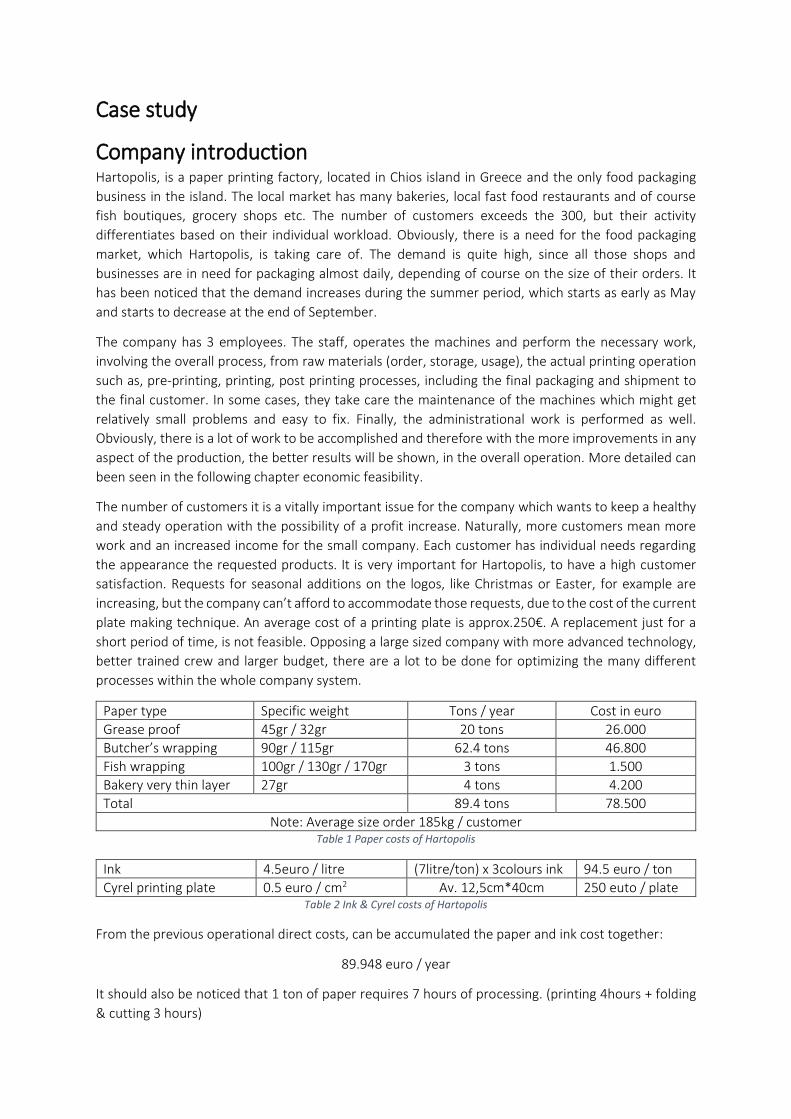
Paper type Specific weight Tons / year Cost in euro
Grease proof 45gr / 32gr 20 tons 26.000
Butcher’s wrapping 90gr / 115gr 62.4 tons 46.800
Fish wrapping 100gr / 130gr / 170gr 3 tons 1.500
Bakery very thin layer 27gr 4 tons 4.200
Total 89.4 tons 78.500
Note: Average size order 185kg / customer Table 1 Paper costs of Hartopolis
Ink 4.5euro / litre (7litre/ton) x 3colours ink 94.5 euro / ton
Cyrel printing plate 0.5 euro / cm2 Av. 12,5cm*40cm 250 euto / plate Table 2 Ink & Cyrel costs of Hartopolis
From the previous operational direct costs, can be accumulated the paper and ink cost together:
89.948 euro / year
It should also be noticed that 1 ton of paper requires 7 hours of processing. (printing 4hours + folding
& cutting 3 hours)
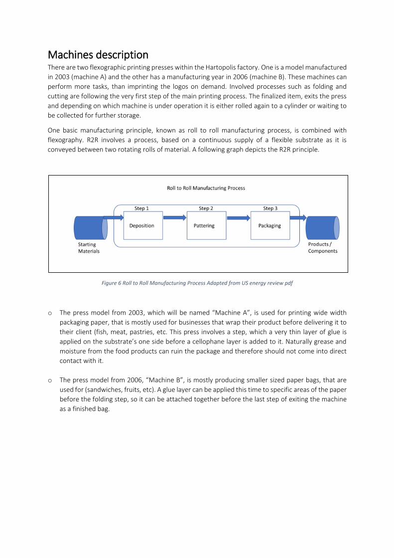
Machines description There are two flexographic printing presses within the Hartopolis factory. One is a model manufactured
in 2003 (machine A) and the other has a manufacturing year in 2006 (machine B). These machines can
perform more tasks, than imprinting the logos on demand. Involved processes such as folding and
cutting are following the very first step of the main printing process. The finalized item, exits the press
and depending on which machine is under operation it is either rolled again to a cylinder or waiting to
be collected for further storage.
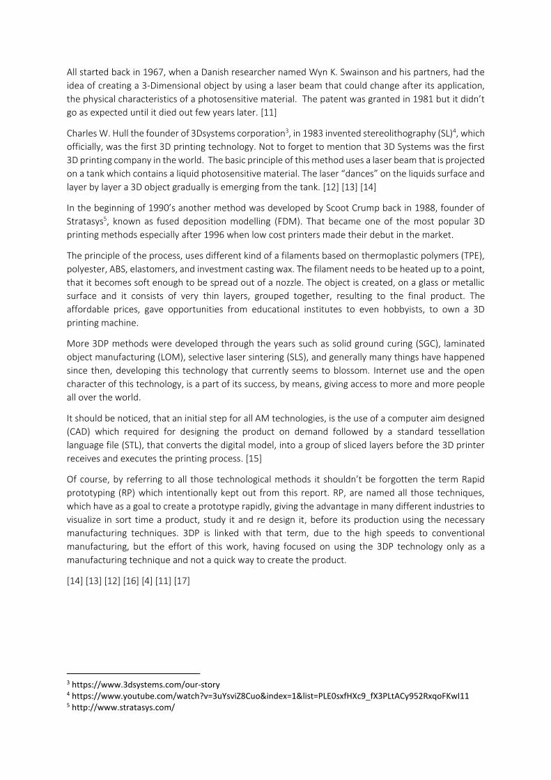
One basic manufacturing principle, known as roll to roll manufacturing process, is combined with
flexography. R2R involves a process, based on a continuous supply of a flexible substrate as it is
conveyed between two rotating rolls of material. A following graph depicts the R2R principle.
Figure 6 Roll to Roll Manufacturing Process Adapted from US energy review pdf
o The press model from 2003, which will be named “Machine A”, is used for printing wide width
packaging paper, that is mostly used for businesses that wrap their product before delivering it to
their client (fish, meat, pastries, etc. This press involves a step, which a very thin layer of glue is
applied on the substrate’s one side before a cellophane layer is added to it. Naturally grease and
moisture from the food products can ruin the package and therefore should not come into direct
contact with it.
o The press model from 2006, “Machine B”, is mostly producing smaller sized paper bags, that are
used for (sandwiches, fruits, etc). A glue layer can be applied this time to specific areas of the paper
before the folding step, so it can be attached together before the last step of exiting the machine
as a finished bag.
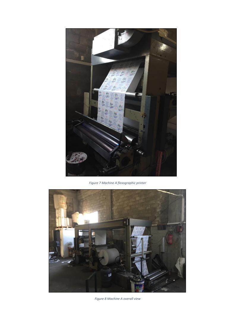
Figure 7 Machine A flexographic printer
Figure 8 Machine A overall view
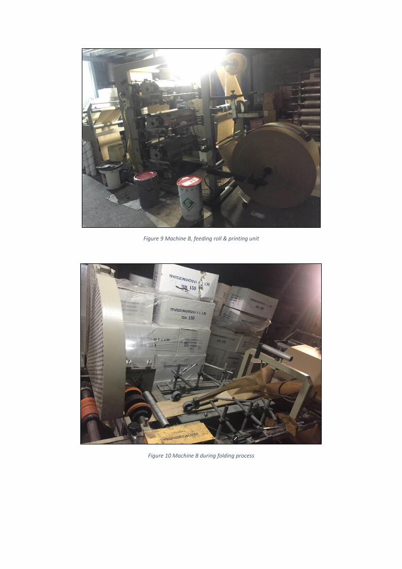
Figure 9 Machine B, feeding roll & printing unit
Figure 10 Machine B during folding process
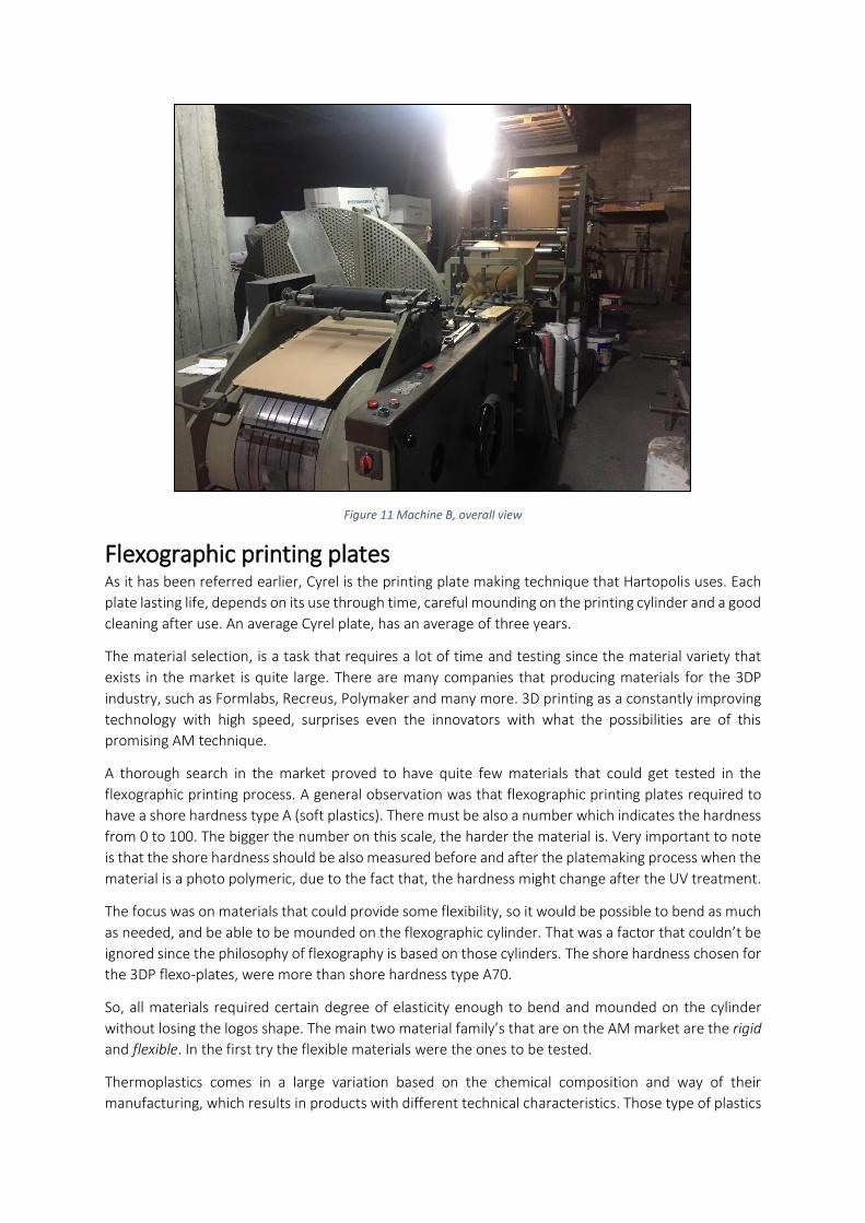
Figure 11 Machine B, overall view
Flexographic printing plates As it has been referred earlier, Cyrel is the printing plate making technique that Hartopolis uses. Each
plate lasting life, depends on its use through time, careful mounding on the printing cylinder and a good
cleaning after use. An average Cyrel plate, has an average of three years.
The material selection, is a task that requires a lot of time and testing since the material variety that
exists in the market is quite large. There are many companies that producing materials for the 3DP
industry, such as Formlabs, Recreus, Polymaker and many more. 3D printing as a constantly improving
technology with high speed, surprises even the innovators with what the possibilities are of this
promising AM technique.
A thorough search in the market proved to have quite few materials that could get tested in the
flexographic printing process. A general observation was that flexographic printing plates required to
have a shore hardness type A (soft plastics). There must be also a number which indicates the hardness
from 0 to 100. The bigger the number on this scale, the harder the material is. Very important to note
is that the shore hardness should be also measured before and after the platemaking process when the
material is a photo polymeric, due to the fact that, the hardness might change after the UV treatment.
The focus was on materials that could provide some flexibility, so it would be possible to bend as much
as needed, and be able to be mounded on the flexographic cylinder. That was a factor that couldn’t be
ignored since the philosophy of flexography is based on those cylinders. The shore hardness chosen for
the 3DP flexo-plates, were more than shore hardness type A70.
So, all materials required certain degree of elasticity enough to bend and mounded on the cylinder
without losing the logos shape. The main two material family’s that are on the AM market are the rigid
and flexible. In the first try the flexible materials were the ones to be tested.
Thermoplastics comes in a large variation based on the chemical composition and way of their
manufacturing, which results in products with different technical characteristics. Those type of plastics
can be given flexible characteristics that could be seemed useful in flexography. Therefor different
industries, uses the materials that suits best in each case. AM and 3D printing has its own categories of
those materials that are also chosen based on the 3D printing process. SLA for example uses different
materials from FDM.
Nowadays polymers and its composites, are everywhere in a large variety of products that we use in
our day life, as well as products in many industries as well. Nevertheless, the application of those
materials requires a constant search for developing polymers and create new ones with new properties.
Combining polymers with different kind of other materials, additives, reinforcing agents and fillers, it
can be possible to create new materials with mechanical characteristics that would serve certain market
needs. Polymer processing improves the technical properties, by adding different chemical and not only
fillers, it can be observed the change of the mechanical, electrical and thermal properties as well as UV
stability. [18]
By contacting 3DHub it was gained valuable technical information regarding the materials that could
be used for the attempt of the 3D printing the 3DP flexographic plates. The best candidates for the
experiment were:
o Recreus filaflex FDM
o Polymaker polyflex FDM
o Formlab’s flexible resin SLA
The recreus and the polymaker are used by an FDM 3D printer. They have slightly different
characteristics with each other, but both are in the same category of the TPE’s. The flexible resin, is a
photopolymer that used by SLA printers. The general characteristics of those three materials, can be
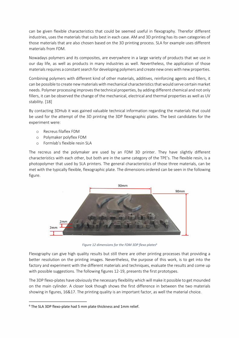
met with the typically flexible, flexographic plate. The dimensions ordered can be seen in the following
figure.
Figure 12 dimensions for the FDM 3DP flexo plates6
Flexography can give high quality results but still there are other printing processes that providing a
better resolution on the printing images. Nevertheless, the purpose of this work, is to get into the
factory and experiment with the different materials and techniques, evaluate the results and come up
with possible suggestions. The following figures 12-19, presents the first prototypes.
The 3DP flexo-plates have obviously the necessary flexibility which will make it possible to get mounded
on the main cylinder. A closer look though shows the first difference in between the two materials
showing in figures, 16&17. The printing quality is an important factor, as well the material choice.
6 The SLA 3DP flexo-plate had 5 mm plate thickness and 1mm relief.
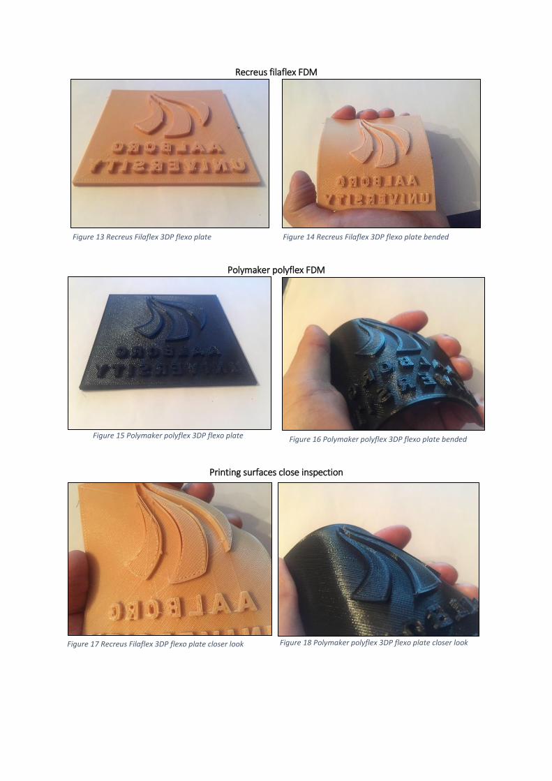
Recreus filaflex FDM
Polymaker polyflex FDM
Printing surfaces close inspection
Figure 13 Recreus Filaflex 3DP flexo plate Figure 14 Recreus Filaflex 3DP flexo plate bended
Figure 15 Polymaker polyflex 3DP flexo plate Figure 16 Polymaker polyflex 3DP flexo plate bended
Figure 17 Recreus Filaflex 3DP flexo plate closer look Figure 18 Polymaker polyflex 3DP flexo plate closer look
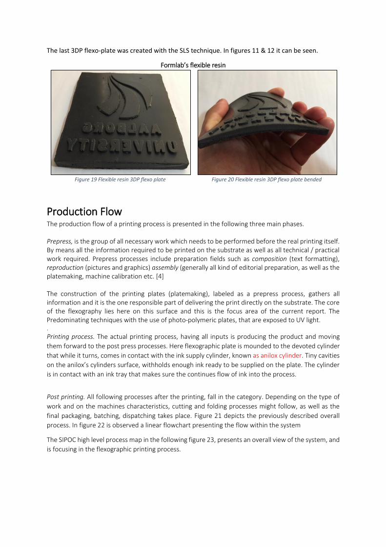
The last 3DP flexo-plate was created with the SLS technique. In figures 11 & 12 it can be seen.
Formlab’s flexible resin
Figure 19 Flexible resin 3DP flexo plate
Figure 20 Flexible resin 3DP flexo plate bended
Production Flow The production flow of a printing process is presented in the following three main phases. Prepress, is the group of all necessary work which needs to be performed before the real printing itself. By means all the information required to be printed on the substrate as well as all technical / practical work required. Prepress processes include preparation fields such as composition (text formatting), reproduction (pictures and graphics) assembly (generally all kind of editorial preparation, as well as the platemaking, machine calibration etc. [4] The construction of the printing plates (platemaking), labeled as a prepress process, gathers all information and it is the one responsible part of delivering the print directly on the substrate. The core of the flexography lies here on this surface and this is the focus area of the current report. The Predominating techniques with the use of photo-polymeric plates, that are exposed to UV light. .
Printing process. The actual printing process, having all inputs is producing the product and moving
them forward to the post press processes. Here flexographic plate is mounded to the devoted cylinder
that while it turns, comes in contact with the ink supply cylinder, known as anilox cylinder. Tiny cavities
on the anilox’s cylinders surface, withholds enough ink ready to be supplied on the plate. The cylinder
is in contact with an ink tray that makes sure the continues flow of ink into the process.
Post printing. All following processes after the printing, fall in the category. Depending on the type of
work and on the machines characteristics, cutting and folding processes might follow, as well as the
final packaging, batching, dispatching takes place. Figure 21 depicts the previously described overall
process. In figure 22 is observed a linear flowchart presenting the flow within the system
The SIPOC high level process map in the following figure 23, presents an overall view of the system, and
is focusing in the flexographic printing process.
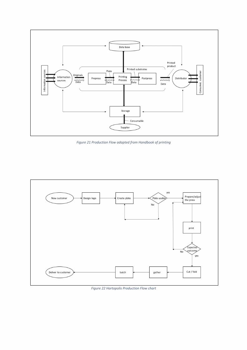
Figure 21 Production Flow adapted from Handbook of printing
Figure 22 Hartopolis Production Flow chart
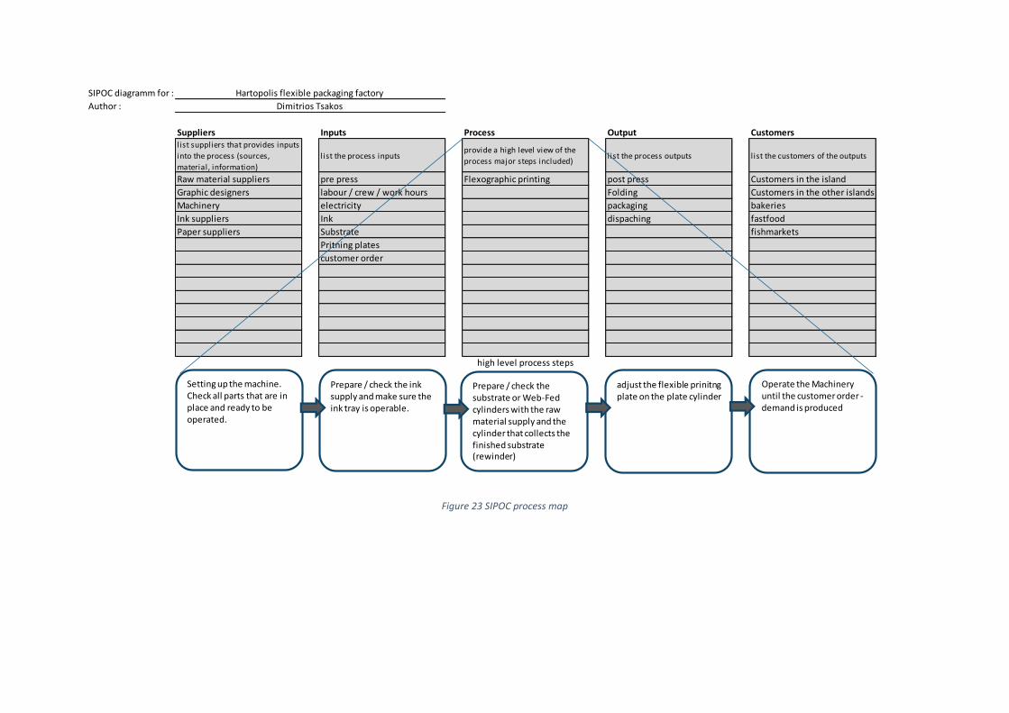
Figure 23 SIPOC process map
SIPOC diagramm for :
Author :
Suppliers Inputs Process Output Customers l ist suppliers that provides inputs
into the process (sources,
material, information)
list the process inputs provide a high level view of the
process major steps included)list the process outputs l ist the customers of the outputs
Raw material suppliers pre press Flexographic printing post press Customers in the island
Graphic designers labour / crew / work hours Folding Customers in the other islands
Machinery electricity packaging bakeries
Ink suppliers Ink dispaching fastfood
Paper suppliers Substrate fishmarkets
Pritning plates
customer order
Hartopolis flexible packaging factory
Dimitrios Tsakos
high level process steps
Setting up the machine.Check all parts that are in place and ready to be operated.
Prepare / check the ink supply and make sure the ink tray is operable.
Prepare / check the substrate or Web-Fed cylinders with the raw material supply and the cylinder that collects the finished substrate (rewinder)
adjust the flexible prinitng plate on the plate cylinder
Operate the Machinery until the customer order -demand is produced
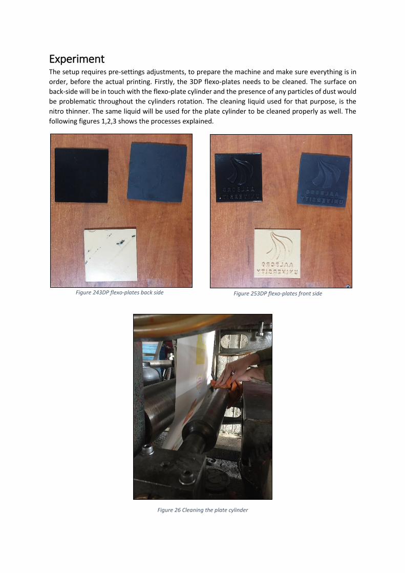
Experiment The setup requires pre-settings adjustments, to prepare the machine and make sure everything is in
order, before the actual printing. Firstly, the 3DP flexo-plates needs to be cleaned. The surface on
back-side will be in touch with the flexo-plate cylinder and the presence of any particles of dust would
be problematic throughout the cylinders rotation. The cleaning liquid used for that purpose, is the
nitro thinner. The same liquid will be used for the plate cylinder to be cleaned properly as well. The
following figures 1,2,3 shows the processes explained.
Figure 26 Cleaning the plate cylinder
Figure 243DP flexo-plates back side Figure 253DP flexo-plates front side
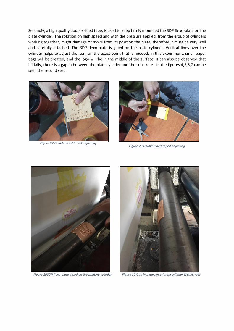
Secondly, a high quality double sided tape, is used to keep firmly mounded the 3DP flexo-plate on the
plate cylinder. The rotation on high speed and with the pressure applied, from the group of cylinders
working together, might damage or move from its position the plate, therefore it must be very well
and carefully attached. The 3DP flexo-plate is glued on the plate cylinder. Vertical lines over the
cylinder helps to adjust the item on the exact point that is needed. In this experiment, small paper
bags will be created, and the logo will be in the middle of the surface. It can also be observed that
initially, there is a gap in between the plate cylinder and the substrate. In the figures 4,5,6,7 can be
seen the second step.
Figure 293DP flexo-plate glued on the printing cylinder
Figure 30 Gap in between printing cylinder & substrate
Figure 27 Double sided taped adjusting Figure 28 Double sided taped adjusting
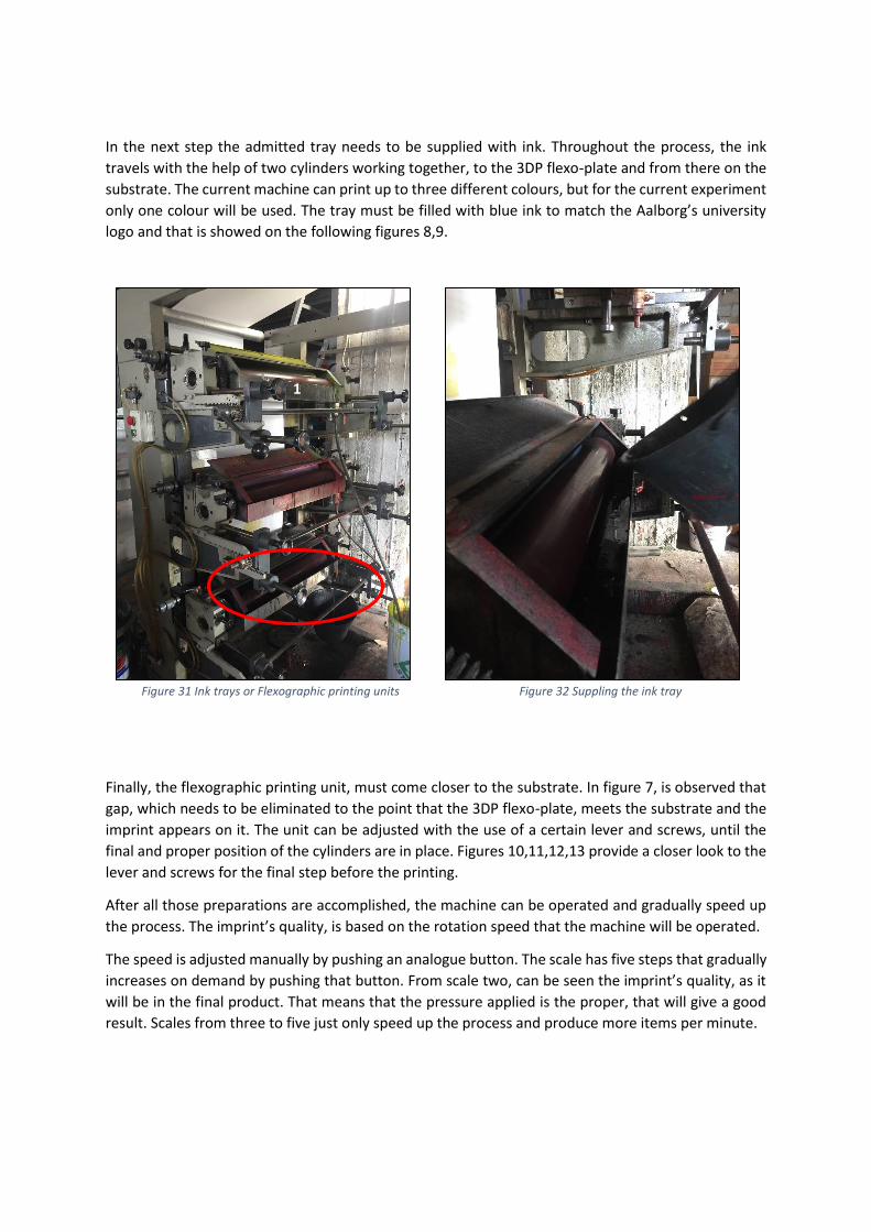
In the next step the admitted tray needs to be supplied with ink. Throughout the process, the ink
travels with the help of two cylinders working together, to the 3DP flexo-plate and from there on the
substrate. The current machine can print up to three different colours, but for the current experiment
only one colour will be used. The tray must be filled with blue ink to match the Aalborg’s university
logo and that is showed on the following figures 8,9.
Figure 31 Ink trays or Flexographic printing units
Figure 32 Suppling the ink tray
Finally, the flexographic printing unit, must come closer to the substrate. In figure 7, is observed that
gap, which needs to be eliminated to the point that the 3DP flexo-plate, meets the substrate and the
imprint appears on it. The unit can be adjusted with the use of a certain lever and screws, until the
final and proper position of the cylinders are in place. Figures 10,11,12,13 provide a closer look to the
lever and screws for the final step before the printing.
After all those preparations are accomplished, the machine can be operated and gradually speed up
the process. The imprint’s quality, is based on the rotation speed that the machine will be operated.
The speed is adjusted manually by pushing an analogue button. The scale has five steps that gradually
increases on demand by pushing that button. From scale two, can be seen the imprint’s quality, as it
will be in the final product. That means that the pressure applied is the proper, that will give a good
result. Scales from three to five just only speed up the process and produce more items per minute.
1
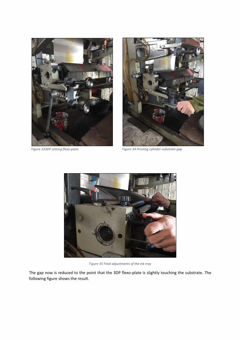
Figure 333DP setting flexo-plate
Figure 34 Printing cylinder-substrate gap
Figure 35 Final adjustments of the ink tray
The gap now is reduced to the point that the 3DP flexo-plate is slightly touching the substrate. The
following figure shows the result.
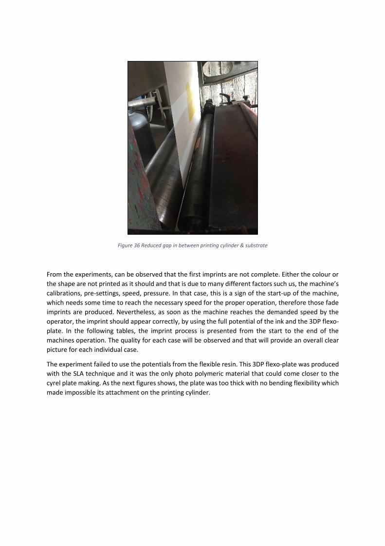
Figure 36 Reduced gap in between printing cylinder & substrate
From the experiments, can be observed that the first imprints are not complete. Either the colour or
the shape are not printed as it should and that is due to many different factors such us, the machine’s
calibrations, pre-settings, speed, pressure. In that case, this is a sign of the start-up of the machine,
which needs some time to reach the necessary speed for the proper operation, therefore those fade
imprints are produced. Nevertheless, as soon as the machine reaches the demanded speed by the
operator, the imprint should appear correctly, by using the full potential of the ink and the 3DP flexo-
plate. In the following tables, the imprint process is presented from the start to the end of the
machines operation. The quality for each case will be observed and that will provide an overall clear
picture for each individual case.
The experiment failed to use the potentials from the flexible resin. This 3DP flexo-plate was produced
with the SLA technique and it was the only photo polymeric material that could come closer to the
cyrel plate making. As the next figures shows, the plate was too thick with no bending flexibility which
made impossible its attachment on the printing cylinder.
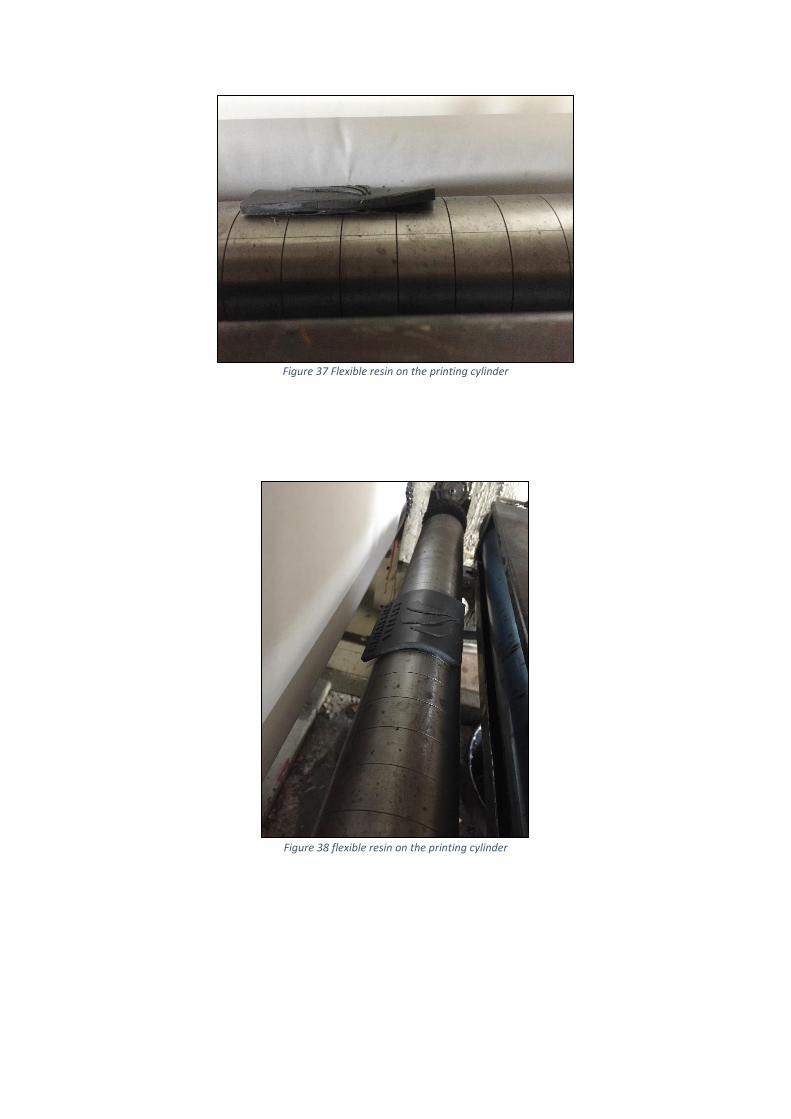
Figure 37 Flexible resin on the printing cylinder
Figure 38 flexible resin on the printing cylinder
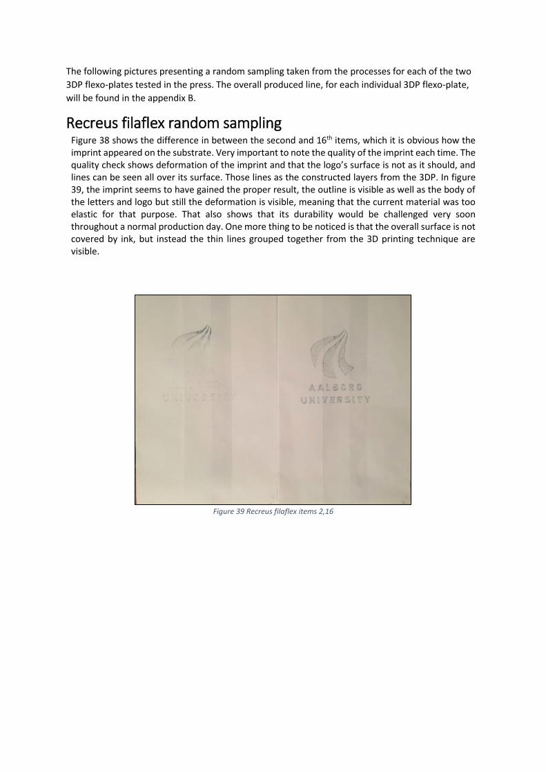
The following pictures presenting a random sampling taken from the processes for each of the two
3DP flexo-plates tested in the press. The overall produced line, for each individual 3DP flexo-plate,
will be found in the appendix B.
Recreus filaflex random sampling Figure 38 shows the difference in between the second and 16th items, which it is obvious how the imprint appeared on the substrate. Very important to note the quality of the imprint each time. The quality check shows deformation of the imprint and that the logo’s surface is not as it should, and lines can be seen all over its surface. Those lines as the constructed layers from the 3DP. In figure 39, the imprint seems to have gained the proper result, the outline is visible as well as the body of the letters and logo but still the deformation is visible, meaning that the current material was too elastic for that purpose. That also shows that its durability would be challenged very soon throughout a normal production day. One more thing to be noticed is that the overall surface is not covered by ink, but instead the thin lines grouped together from the 3D printing technique are visible.
Figure 39 Recreus filaflex items 2,16
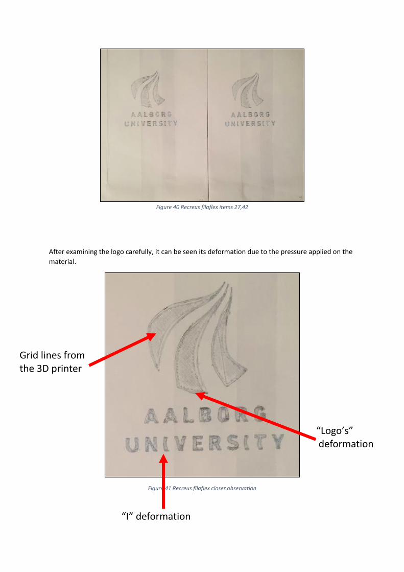
Figure 40 Recreus filaflex items 27,42
After examining the logo carefully, it can be seen its deformation due to the pressure applied on the
material.
Figure 41 Recreus filaflex closer observation
“I” deformation
Grid lines from the 3D printer
“Logo’s” deformation
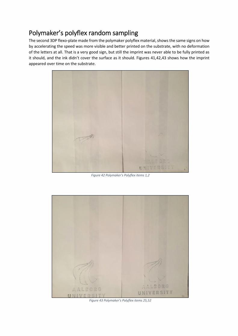
Polymaker’s polyflex random sampling The second 3DP flexo-plate made from the polymaker polyflex material, shows the same signs on how
by accelerating the speed was more visible and better printed on the substrate, with no deformation
of the letters at all. That is a very good sign, but still the imprint was never able to be fully printed as
it should, and the ink didn’t cover the surface as it should. Figures 41,42,43 shows how the imprint
appeared over time on the substrate.
Figure 42 Polymaker's Polyflex items 1,2
Figure 43 Polymaker's Polyflex items 25,52
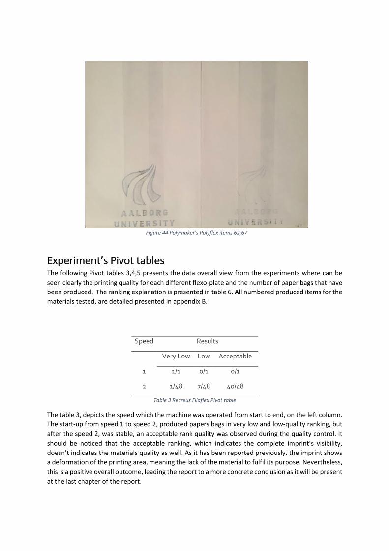
Figure 44 Polymaker's Polyflex items 62,67
Experiment’s Pivot tables The following Pivot tables 3,4,5 presents the data overall view from the experiments where can be
seen clearly the printing quality for each different flexo-plate and the number of paper bags that have
been produced. The ranking explanation is presented in table 6. All numbered produced items for the
materials tested, are detailed presented in appendix B.
Speed Results
Very Low Low Acceptable
1 1/1 0/1 0/1
2 1/48 7/48 40/48
Table 3 Recreus Filaflex Pivot table
The table 3, depicts the speed which the machine was operated from start to end, on the left column.
The start-up from speed 1 to speed 2, produced papers bags in very low and low-quality ranking, but
after the speed 2, was stable, an acceptable rank quality was observed during the quality control. It
should be noticed that the acceptable ranking, which indicates the complete imprint’s visibility,
doesn’t indicates the materials quality as well. As it has been reported previously, the imprint shows
a deformation of the printing area, meaning the lack of the material to fulfil its purpose. Nevertheless,
this is a positive overall outcome, leading the report to a more concrete conclusion as it will be present
at the last chapter of the report.
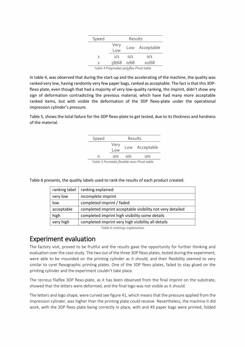
Speed Results
Very Low
Low Acceptable
1 1/1 0/1 0/1
2 58/68 0/68 10/68 Table 4 Polymaker polyflex Pivot table
In table 4, was observed that during the start-up and the accelerating of the machine, the quality was
ranked very low, having randomly very few paper bags, ranked as acceptable. The fact is that this 3DP-
flexo plate, even though that had a majority of very low-quality ranking, the imprint, didn’t show any
sign of deformation contradicting the previous material, which have had many more acceptable
ranked items, but with visible the deformation of the 3DP flexo-plate under the operational
impression cylinder’s pressure.
Table 5, shows the total failure for the 3DP flexo-plate to get tested, due to its thickness and hardness
of the material.
Speed Results
Very Low
Low Acceptable
0 0/0 0/0 0/0 Table 5 Formlabs flexible resin Pivot table
Table 6 presents, the quality labels used to rank the results of each product created.
ranking label ranking explained
very low incomplete imprint
low completed imprint / faded
acceptable completed imprint acceptable visibility not very detailed
high completed imprint high visibility some details
very high completed imprint very high visibility all details Table 6 rankings explanation
Experiment evaluation The factory visit, proved to be fruitful and the results gave the opportunity for further thinking and
evaluation over the case study. The two out of the three 3DP flexo plates, tested during the experiment,
were able to be mounded on the printing cylinder as it should, and their flexibility seemed to very
similar to cyrel flexographic printing plates. One of the 3DP flexo plates, failed to stay glued on the
printing cylinder and the experiment couldn’t take place.
The recreus filaflex 3DP flexo-plate, as it has been observed from the final imprint on the substrate,
showed that the letters were deformed, and the final logo was not visible as it should.
The letters and logo shape, were curved see figure 41, which means that the pressure applied from the
impression cylinder, was higher than the printing plate could receive. Nevertheless, the machine it did
work, with the 3DP flexo plate being correctly in place, with and 49 paper bags were printed, folded
and exited the process. Figures 39,40, shows randomly taken steps from the process. The whole process
can be found in appendix B.
The polymaker polyflex, seemed to be a flexible material as well and it could be used and attached on
the printing cylinder. The imprint was better than the previous material which appeared to be more
clear and complete on the substrate. The experiment showed that this material could withstand
pressure with no any deformation at all on the surface of the 3DP flexo plate.
A fact is that to gain a more spherical knowledge on their strength under pressure and general durability
and material life cycle, the experiment in both cases should be tested for more time. Running for more
time the machine, could have shown for how long the materials can be used under realistic conditions
and a better understanding would have given a more concrete result for its mechanical strengths.
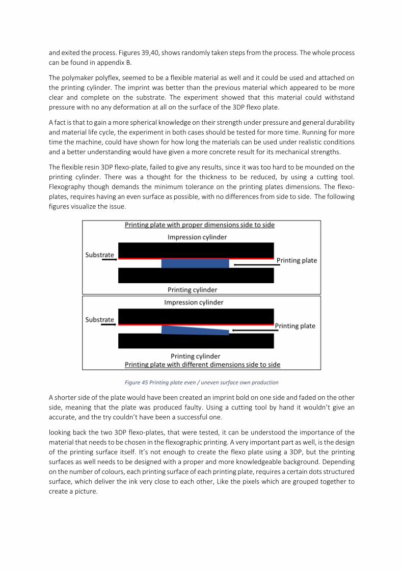
The flexible resin 3DP flexo-plate, failed to give any results, since it was too hard to be mounded on the
printing cylinder. There was a thought for the thickness to be reduced, by using a cutting tool.
Flexography though demands the minimum tolerance on the printing plates dimensions. The flexo-
plates, requires having an even surface as possible, with no differences from side to side. The following
figures visualize the issue.
Figure 45 Printing plate even / uneven surface own production
A shorter side of the plate would have been created an imprint bold on one side and faded on the other
side, meaning that the plate was produced faulty. Using a cutting tool by hand it wouldn’t give an
accurate, and the try couldn’t have been a successful one.
looking back the two 3DP flexo-plates, that were tested, it can be understood the importance of the
material that needs to be chosen in the flexographic printing. A very important part as well, is the design
of the printing surface itself. It’s not enough to create the flexo plate using a 3DP, but the printing
surfaces as well needs to be designed with a proper and more knowledgeable background. Depending
on the number of colours, each printing surface of each printing plate, requires a certain dots structured
surface, which deliver the ink very close to each other, Like the pixels which are grouped together to
create a picture.
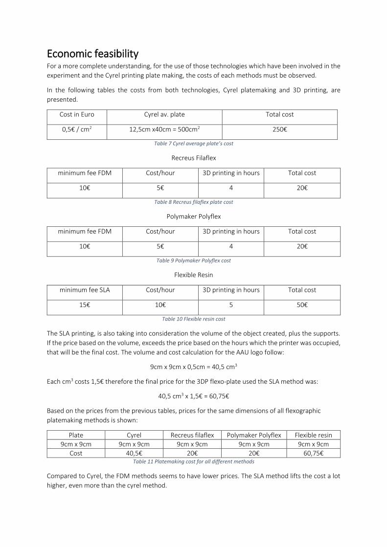
Economic feasibility For a more complete understanding, for the use of those technologies which have been involved in the
experiment and the Cyrel printing plate making, the costs of each methods must be observed.
In the following tables the costs from both technologies, Cyrel platemaking and 3D printing, are
presented.
Cost in Euro Cyrel av. plate Total cost
0,5€ / cm2 12,5cm x40cm = 500cm2 250€
Table 7 Cyrel average plate’s cost
Recreus Filaflex
minimum fee FDM Cost/hour 3D printing in hours Total cost
10€ 5€ 4 20€
Table 8 Recreus filaflex plate cost
Polymaker Polyflex
minimum fee FDM Cost/hour 3D printing in hours Total cost
10€ 5€ 4 20€
Table 9 Polymaker Polyflex cost
Flexible Resin
minimum fee SLA Cost/hour 3D printing in hours Total cost
15€ 10€ 5 50€
Table 10 Flexible resin cost
The SLA printing, is also taking into consideration the volume of the object created, plus the supports.
If the price based on the volume, exceeds the price based on the hours which the printer was occupied,
that will be the final cost. The volume and cost calculation for the AAU logo follow:
9cm x 9cm x 0,5cm = 40,5 cm3
Each cm3 costs 1,5€ therefore the final price for the 3DP flexo-plate used the SLA method was:
40,5 cm3 x 1,5€ = 60,75€
Based on the prices from the previous tables, prices for the same dimensions of all flexographic
platemaking methods is shown:
Plate Cyrel Recreus filaflex Polymaker Polyflex Flexible resin
9cm x 9cm 9cm x 9cm 9cm x 9cm 9cm x 9cm 9cm x 9cm
Cost 40,5€ 20€ 20€ 60,75€ Table 11 Platemaking cost for all different methods
Compared to Cyrel, the FDM methods seems to have lower prices. The SLA method lifts the cost a lot
higher, even more than the cyrel method.
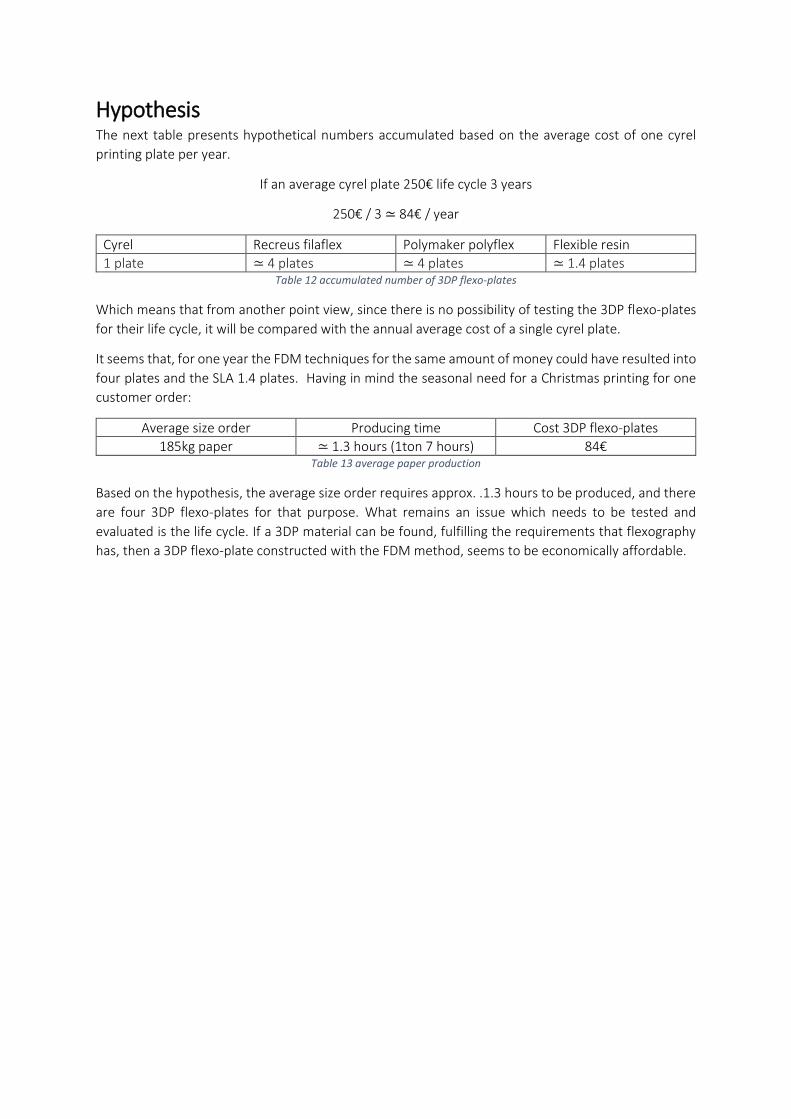
Hypothesis The next table presents hypothetical numbers accumulated based on the average cost of one cyrel
printing plate per year.
If an average cyrel plate 250€ life cycle 3 years
250€ / 3 ≃ 84€ / year
Cyrel Recreus filaflex Polymaker polyflex Flexible resin
1 plate ≃ 4 plates ≃ 4 plates ≃ 1.4 plates Table 12 accumulated number of 3DP flexo-plates
Which means that from another point view, since there is no possibility of testing the 3DP flexo-plates
for their life cycle, it will be compared with the annual average cost of a single cyrel plate.
It seems that, for one year the FDM techniques for the same amount of money could have resulted into
four plates and the SLA 1.4 plates. Having in mind the seasonal need for a Christmas printing for one
customer order:
Average size order Producing time Cost 3DP flexo-plates
185kg paper ≃ 1.3 hours (1ton 7 hours) 84€ Table 13 average paper production
Based on the hypothesis, the average size order requires approx. .1.3 hours to be produced, and there
are four 3DP flexo-plates for that purpose. What remains an issue which needs to be tested and
evaluated is the life cycle. If a 3DP material can be found, fulfilling the requirements that flexography
has, then a 3DP flexo-plate constructed with the FDM method, seems to be economically affordable.
Conclusion Throughout this project, the theoretical background, the different readings and the case study, were
grouped together and resulted to this work. It is quite fascinating for someone to see how it was built
up during that period and gladly there have been concrete results that gave some extra information
regarding the 3D printing technology and flexographic packaging paper printing.
To start with a general overview, it seems that the 3D printing technology could be used effectively
for flexographic printers. The flexographic plates that have been used in the project were only three
available options, based on the circumstances, which narrowed down the possibilities of this
technological merging. Nevertheless, the problem statement, seems to be positively answered and
that 3D printing technologies, can be applied for producing flexographic printing plates.
With a more detailed look in the current flow process of the flexographic printing, it seems that the
cyrel platemaking is an expensive method, but comparing it with its life cycle seems to be a
trustworthy product, which can be utilized in flexography effectively. It always needs to be taken into
consideration that this work tried to find out an alternative, which seems technically feasible although
the 3DP flexo-plates costs seems to be in a range including lowered prices than cyrel and a lot higher.
The material selection it should be the main investigation of this issue, since that is what can make
the difference and provide as closer as possible the same printing results to the dominating printing
plate making techniques. More time in a laboratory and the opportunity to experiment with more
materials in different harness scales. As it has been reported earlier in this work, the applied pressures
during the rotation of the cylinders are one of the main factors, to influence the life cycle of the
printing plate and therefore the proper materials are important to be chosen, with the most suitable
mechanical characteristics.
The printing surface of the printing plate, should also be the focus since FDM method, cannot produce
a unified surface, which results in a printing with visible grids. Those grids they could have been
avoided if a in final process, the product could be sprayed with some kind of coating, or polished to
result a smoothed surface. Here again a laboratory would have been the best way to test those ideas.
As the economical overview showed, depending on which 3D printing method will be used, the costs
can vary, but nevertheless, the comparison to cyrel and its long-life cycle seems not to be competitive.
It should be also noticed that apart the direct cost of a cyrel plate, the lead time, that can be in
between one and two weeks, has an impact on the production and here 3DP gives the advantage of a
direct use in house, eliminating the platemaking time and the cost of not being able to print in the
factory, while waiting for the cyrel delivery. It should be also noticed the advantage of replacing four
manufacturing processes in the photo-polymeric method with only one 3D printer. In that case,
training is needed as well, since the 3DP technology requires experience in using the printer, CAD
programs and a very good computers skill.
This work could initiate a further testing and experimentation. There is a need for the most suitable
materials and finishing methods to be chosen, to create products effectively and efficiently, which
could be used in flexographic printing packaging industry. The utilization of this alternative to the
current printing plate manufacturing method, has potentials that needs attention, which hopefully in
the future could influence and the packaging industry.
References
[1] C. European , “The new SME definition,” Concerning the definition of micro, small, medium
sized enterprises, 2003.
[2] L. T. Saunders, Research methods for bussines students 4th edition, Edinburgh , England:
Pearson education, 2007.
[3] F. Rees, Johannes Gutenberg: Inventor of the Printing Press, Mineapolis USA : compass point
books , 2006.
[4] H. Kipphan, Handbook of print media: technologies and production methods, Berlin: Springer
, 2014.
[5] The ultimate guid to flexo printing , “Focus Labels,” 2016 Focus Label Ltd.. [Online]. Available:
http://blog.focuslabel.com/free-guide-ultimate-guide-to-flexo-
printing?hsCtaTracking=9153646b-09d9-49ef-8799-9ba388bea850%7Ca1b187e1-adcb-4146-
b0da-92b7ed2fa989. [Accessed 2016 Focus Label Ltd.].
[6] M. P. Groover, Fundumentals of modern manufacturing, World Color, 2010.
[7] Dupont, “F l e x o g r a p h i c P r i n t i n g P l a t e s - processing manual for cyrel,” [Online].
Available: http://www.monochrom.gr/UserFiles/Cyrelmanual_e.pdf.
[8] N. Nylonflex, “http://www.flintgrp.com,” 03 2017. [Online]. Available:
http://www.flintgrp.com/media/1263/nyloflex_next_en.pdf.
[9] “Kodak,” 2017. [Online]. Available:
https://www.kodak.com/DK/da/print/Products/Flexographic/FLEXCEL_SR_Flexographic_Plat
es/default.htm.
[10] “www.flintgrp.com,” 2017. [Online]. Available:
http://www.flintgrp.com/en/products/flexographic-products/nyloflex/.
[11] B. Wyn K. Swainson and Stephen, “THREE-DIMENSIONAL SYSTEMS”. U.S Patent 4,288,861, 22
January 1979.
[12] C. W. Hull, “3D printing (stereolithography),” 6th May 2014. [Online]. Available:
https://www.youtube.com/watch?v=3uYsviZ8Cuo&index=1&list=PLE0sxfHXc9_fX3PLtACy952
RxqoFKwI11.
[13] “3Dsystems,” 2017. [Online]. Available: https://www.3dsystems.com/our-story.
[14] Wohlers, “History of Additive Manufacturing,” 2014.
[15] A. H. Kaufui V.Wong, “A Review of AdditiveManufacturing,” International Scholarly Research
Network, p. 10, 17 June 2012.
[16] H. L. Jonathan D. Hiller, “STL 2.0: A PROPOSAL FOR A UNIVERSAL MULTI-MATERIAL ADDITIVE
MANUFACTURING FILE FORMAT”.
[17] P. W. Peter Troxler, “BENDING THE RULES: THE FAB LAB INNOVATION ECOLOGY,” Square One
Dr Peter Troxler, Rotterdam, The Netherlands 2University of Applied Sciences and Arts
Lucerne, Switzerland.
[18] B. A.-Z. S.-W. C. M. S. Adib Kalantar Mehrjerdi, “Mechanical and Thermo-Physical Properties
of High-Density,” Wiley Periodicals, Inc., January 2013.
[19] Q. T. Review, “Innovating Clean Energy Technologies in Advanced Manufacturing,” U.S
Department of Energy, 2015.
[20] W. report, “History of Additive Manufacturing,” 2014.
[21] S. Lagier, “3D Printed injection mould tools:,” Aalborg University, Copenhagen, 2016.
[22] R. S.-M. H.-F. Krebs, “Roll-to-Roll fabrication of large area functional organic materials,”
Journal of Polymer Science Part B: Polymer Physics, 2012.
[23] R. Faddoul, N. Reverdy-Bruas, A. Blayo, T. Haas and C. Zeilmann, “Optimisation of silver paste
for flexography printing on LTCC substrate,” Microelectronics Reliability, vol. 52, no. 7, pp.
1483-1491, 2012.
[24] efunda, “efunda,” 2017. [Online]. Available:
http://www.efunda.com/processes/rapid_prototyping/intro.cfm.
[25] S. D. S. M. P. Dragoljub Novaković, “A MODEL FOR IMPROVING THE FLEXOGRAPHIC PRINTING
PLATE MAKING PROCESS,” ISSN 1330-3651.
[26] “Focus Label Ltd.,” Focus Label, 2016. [Online]. Available: http://www.focuslabel.com/reflex-
machine.
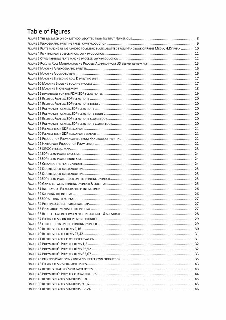
Table of Figures FIGURE 1 THE RESEARCH ONION METHOD, ADOPTED FROM INSTITUT NUMERIQUE ................................................................... 8 FIGURE 2 FLEXOGRAPHIC PRINTING PRESS, OWN PRODUCTION ............................................................................................. 9 FIGURE 3 PLATE MAKING USING A PHOTO POLYMERIC PLATE, ADOPTED FROM HANDBOOK OF PRINT MEDIA, H.KIPPHAN .............. 10 FIGURE 4 PRINTING PLATE DESCRIPTION, OWN PRODUCTION .............................................................................................. 11 FIGURE 5 CYREL PRINTING PLATE MAKING PROCESS, OWN PRODUCTION ............................................................................... 12 FIGURE 6 ROLL TO ROLL MANUFACTURING PROCESS ADAPTED FROM US ENERGY REVIEW PDF................................................. 15 FIGURE 7 MACHINE A FLEXOGRAPHIC PRINTER ................................................................................................................ 16 FIGURE 8 MACHINE A OVERALL VIEW ............................................................................................................................ 16 FIGURE 9 MACHINE B, FEEDING ROLL & PRINTING UNIT .................................................................................................... 17 FIGURE 10 MACHINE B DURING FOLDING PROCESS .......................................................................................................... 17 FIGURE 11 MACHINE B, OVERALL VIEW ......................................................................................................................... 18 FIGURE 12 DIMENSIONS FOR THE FDM 3DP FLEXO PLATES ............................................................................................... 19 FIGURE 13 RECREUS FILAFLEX 3DP FLEXO PLATE ............................................................................................................. 20 FIGURE 14 RECREUS FILAFLEX 3DP FLEXO PLATE BENDED .................................................................................................. 20 FIGURE 15 POLYMAKER POLYFLEX 3DP FLEXO PLATE ........................................................................................................ 20 FIGURE 16 POLYMAKER POLYFLEX 3DP FLEXO PLATE BENDED ............................................................................................. 20 FIGURE 17 RECREUS FILAFLEX 3DP FLEXO PLATE CLOSER LOOK ........................................................................................... 20 FIGURE 18 POLYMAKER POLYFLEX 3DP FLEXO PLATE CLOSER LOOK ...................................................................................... 20 FIGURE 19 FLEXIBLE RESIN 3DP FLEXO PLATE .................................................................................................................. 21 FIGURE 20 FLEXIBLE RESIN 3DP FLEXO PLATE BENDED ...................................................................................................... 21 FIGURE 21 PRODUCTION FLOW ADAPTED FROM HANDBOOK OF PRINTING ............................................................................ 22 FIGURE 22 HARTOPOLIS PRODUCTION FLOW CHART ........................................................................................................ 22 FIGURE 23 SIPOC PROCESS MAP .................................................................................................................................. 23 FIGURE 243DP FLEXO-PLATES BACK SIDE ....................................................................................................................... 24 FIGURE 253DP FLEXO-PLATES FRONT SIDE ..................................................................................................................... 24 FIGURE 26 CLEANING THE PLATE CYLINDER ..................................................................................................................... 24 FIGURE 27 DOUBLE SIDED TAPED ADJUSTING .................................................................................................................. 25 FIGURE 28 DOUBLE SIDED TAPED ADJUSTING .................................................................................................................. 25 FIGURE 293DP FLEXO-PLATE GLUED ON THE PRINTING CYLINDER ........................................................................................ 25 FIGURE 30 GAP IN BETWEEN PRINTING CYLINDER & SUBSTRATE .......................................................................................... 25 FIGURE 31 INK TRAYS OR FLEXOGRAPHIC PRINTING UNITS .................................................................................................. 26 FIGURE 32 SUPPLING THE INK TRAY ............................................................................................................................... 26 FIGURE 333DP SETTING FLEXO-PLATE ........................................................................................................................... 27 FIGURE 34 PRINTING CYLINDER-SUBSTRATE GAP .............................................................................................................. 27 FIGURE 35 FINAL ADJUSTMENTS OF THE INK TRAY ............................................................................................................ 27 FIGURE 36 REDUCED GAP IN BETWEEN PRINTING CYLINDER & SUBSTRATE ............................................................................. 28 FIGURE 37 FLEXIBLE RESIN ON THE PRINTING CYLINDER ..................................................................................................... 29 FIGURE 38 FLEXIBLE RESIN ON THE PRINTING CYLINDER ..................................................................................................... 29 FIGURE 39 RECREUS FILAFLEX ITEMS 2,16 ...................................................................................................................... 30 FIGURE 40 RECREUS FILAFLEX ITEMS 27,42 .................................................................................................................... 31 FIGURE 41 RECREUS FILAFLEX CLOSER OBSERVATION ........................................................................................................ 31 FIGURE 42 POLYMAKER'S POLYFLEX ITEMS 1,2 ............................................................................................................... 32 FIGURE 43 POLYMAKER'S POLYFLEX ITEMS 25,52 ........................................................................................................... 32 FIGURE 44 POLYMAKER'S POLYFLEX ITEMS 62,67 ........................................................................................................... 33 FIGURE 45 PRINTING PLATE EVEN / UNEVEN SURFACE OWN PRODUCTION ............................................................................. 35 FIGURE 46 FLEXIBLE RESIN’S CHARACTERISTICS ................................................................................................................ 43 FIGURE 47 RECREUS FILAFLXEX'S CHARACTERISTICS .......................................................................................................... 43 FIGURE 48 POLYMAKER’S POLYFLEX CHARACTERISTICS ...................................................................................................... 44 FIGURE 49 RECREUS FILAFLEX'S IMPRINTS 1-8 ................................................................................................................ 45 FIGURE 50 RECREUS FILAFLEX'S IMPRINTS 9-16 .............................................................................................................. 45 FIGURE 51 RECREUS FILAFLEX'S IMPRINTS 17-24 ............................................................................................................ 46
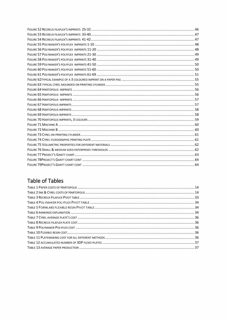
FIGURE 52 RECREUS FILAFLEX'S IMPRINTS 25-32 ............................................................................................................ 46 FIGURE 53 RECREUS FILAFLEX'S IMPRINTS 33-40 ............................................................................................................ 47 FIGURE 54 RECREUS FILAFLEX'S IMPRINTS 41-42 ............................................................................................................ 47 FIGURE 55 POLYMAKER'S POLYFLEX IMPRINTS 1-10 ........................................................................................................ 48 FIGURE 56 POLYMAKER'S POLYFLEX IMPRINTS 11-20 ...................................................................................................... 48 FIGURE 57 POLYMAKER'S POLYFLEX IMPRINTS 21-30 ...................................................................................................... 49 FIGURE 58 POLYMAKER'S POLYFLEX IMPRINTS 31-40 ...................................................................................................... 49 FIGURE 59 POLYMAKER'S POLYFLEX IMPRINTS 41-50 ...................................................................................................... 50 FIGURE 60 POLYMAKER'S POLYFLEX IMPRINTS 51-60 ...................................................................................................... 50 FIGURE 61 POLYMAKER'S POLYFLEX IMPRINTS 61-69 ...................................................................................................... 51 FIGURE 62TYPICAL EXAMPLE OF A 3 COLOURED IMPRINT ON A PAPER PAG ............................................................................ 55 FIGURE 63 TYPICAL CYREL MOUNDED ON PRINTING CYLINDER ............................................................................................. 55 FIGURE 64 HARTOPOLIS IMPRINTS ............................................................................................................................... 56 FIGURE 65 HARTOPOLIS IMPRINTS ............................................................................................................................... 56 FIGURE 66 HARTOPOLIS IMPRINTS ............................................................................................................................... 57 FIGURE 67 HARTOPOLIS IMPRINTS ................................................................................................................................ 57 FIGURE 68 HARTOPOLIS IMPRINTS ................................................................................................................................ 58 FIGURE 69 HARTOPOLIS IMPRINTS ................................................................................................................................ 58 FIGURE 70 HARTOPOLIS IMPRINTS, 3 COLOURS ............................................................................................................... 59 FIGURE 71 MACHINE A .............................................................................................................................................. 60 FIGURE 72 MACHINE B .............................................................................................................................................. 60 FIGURE 73 CYREL ON PRINTING CYLINDER ....................................................................................................................... 61 FIGURE 74 CYREL FLEXOGRAPHIC PRINTING PLATE ............................................................................................................ 61 FIGURE 75 VOLUMETRIC PROPERTIES FOR DIFFERENT MATERIALS ........................................................................................ 62 FIGURE 76 SMALL & MEDIUM SIZED ENTERPRISES THRESHOLDS .......................................................................................... 62 FIGURE 77 PROJECT'S GANTT CHART ............................................................................................................................. 63 FIGURE 78PROJECT'S GANTT CHART CONT ..................................................................................................................... 64 FIGURE 79PROJECT'S GANTT CHART CONT ..................................................................................................................... 64
Table of Tables TABLE 1 PAPER COSTS OF HARTOPOLIS .......................................................................................................................... 14 TABLE 2 INK & CYREL COSTS OF HARTOPOLIS .................................................................................................................. 14 TABLE 3 RECREUS FILAFLEX PIVOT TABLE ........................................................................................................................ 33 TABLE 4 POLYMAKER POLYFLEX PIVOT TABLE ............................................................................................................. 34 TABLE 5 FORMLABS FLEXIBLE RESIN PIVOT TABLE ........................................................................................................ 34 TABLE 6 RANKINGS EXPLANATION ................................................................................................................................. 34 TABLE 7 CYREL AVERAGE PLATE’S COST .......................................................................................................................... 36 TABLE 8 RECREUS FILAFLEX PLATE COST .......................................................................................................................... 36 TABLE 9 POLYMAKER POLYFLEX COST ............................................................................................................................ 36 TABLE 10 FLEXIBLE RESIN COST..................................................................................................................................... 36 TABLE 11 PLATEMAKING COST FOR ALL DIFFERENT METHODS ............................................................................................. 36 TABLE 12 ACCUMULATED NUMBER OF 3DP FLEXO-PLATES ................................................................................................ 37 TABLE 13 AVERAGE PAPER PRODUCTION ........................................................................................................................ 37
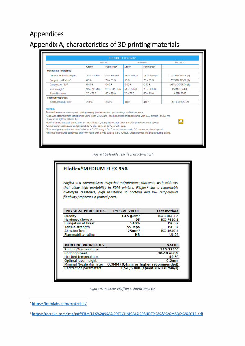
Appendices
Appendix A, characteristics of 3D printing materials
Figure 46 Flexible resin’s characteristics7
Figure 47 Recreus Filaflxex's characteristics8
7 https://formlabs.com/materials/ 8 https://recreus.com/img/pdf/FILAFLEX%2095A%20TECHNICAL%20SHEET%20&%20MSDS%202017.pdf
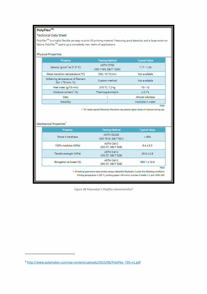
Figure 48 Polymaker’s Polyflex characteristics9
9 http://www.polymaker.com/wp-content/uploads/2015/06/PolyFlex_TDS-v1.pdf
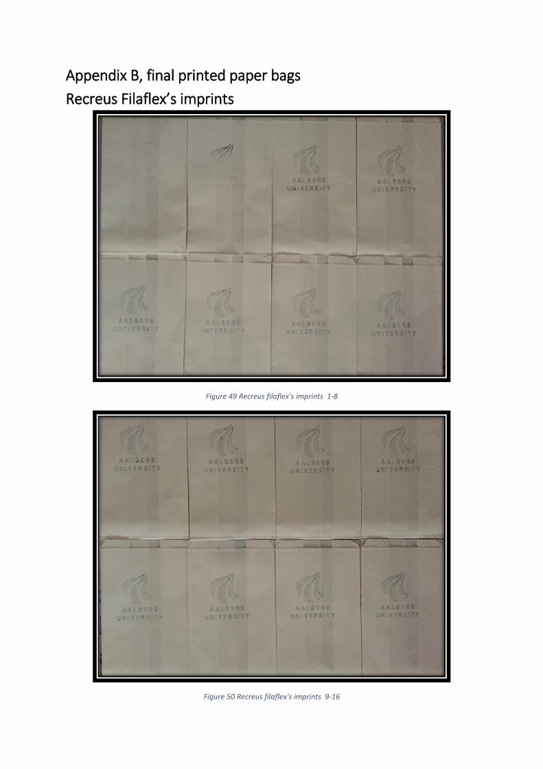
Appendix B, final printed paper bags
Recreus Filaflex’s imprints
Figure 49 Recreus filaflex's imprints 1-8
Figure 50 Recreus filaflex's imprints 9-16
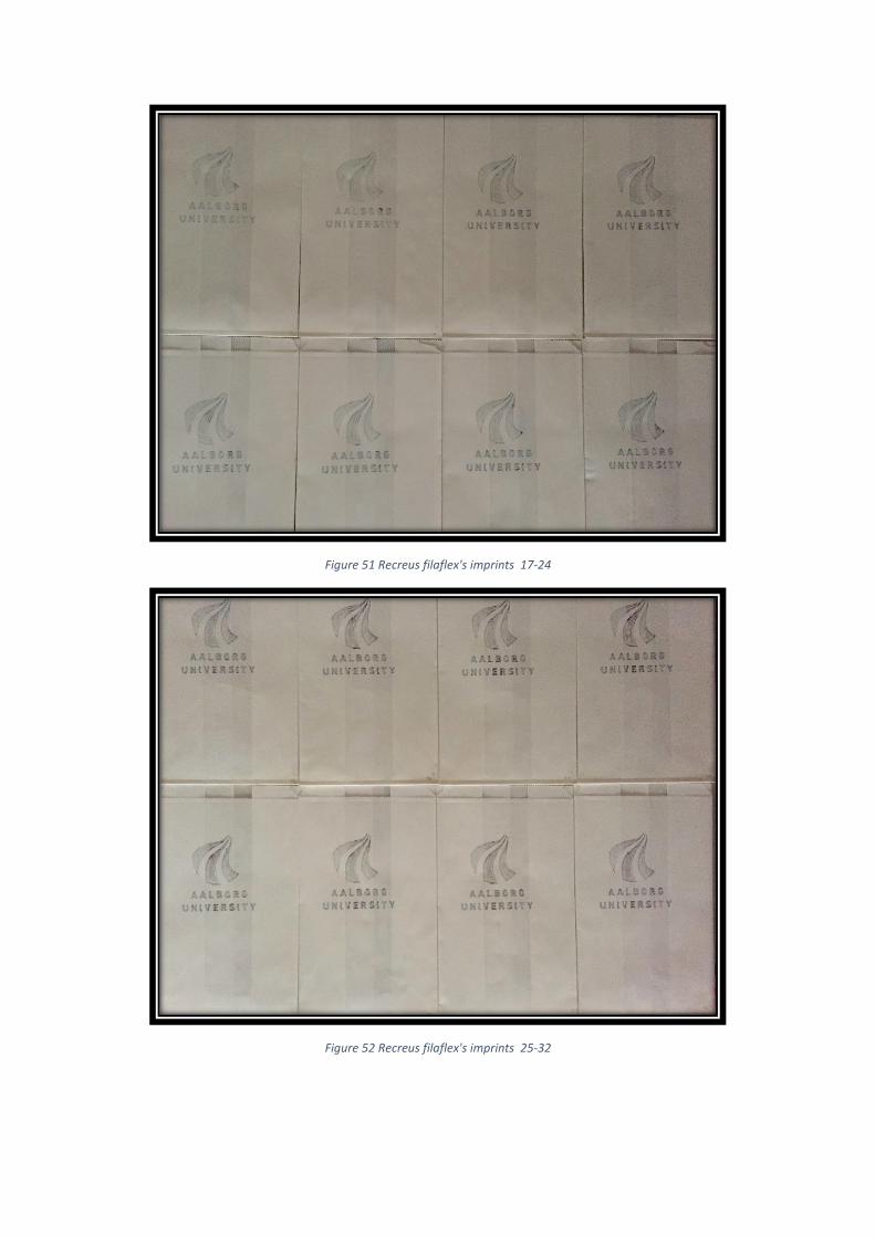
Figure 51 Recreus filaflex's imprints 17-24
Figure 52 Recreus filaflex's imprints 25-32
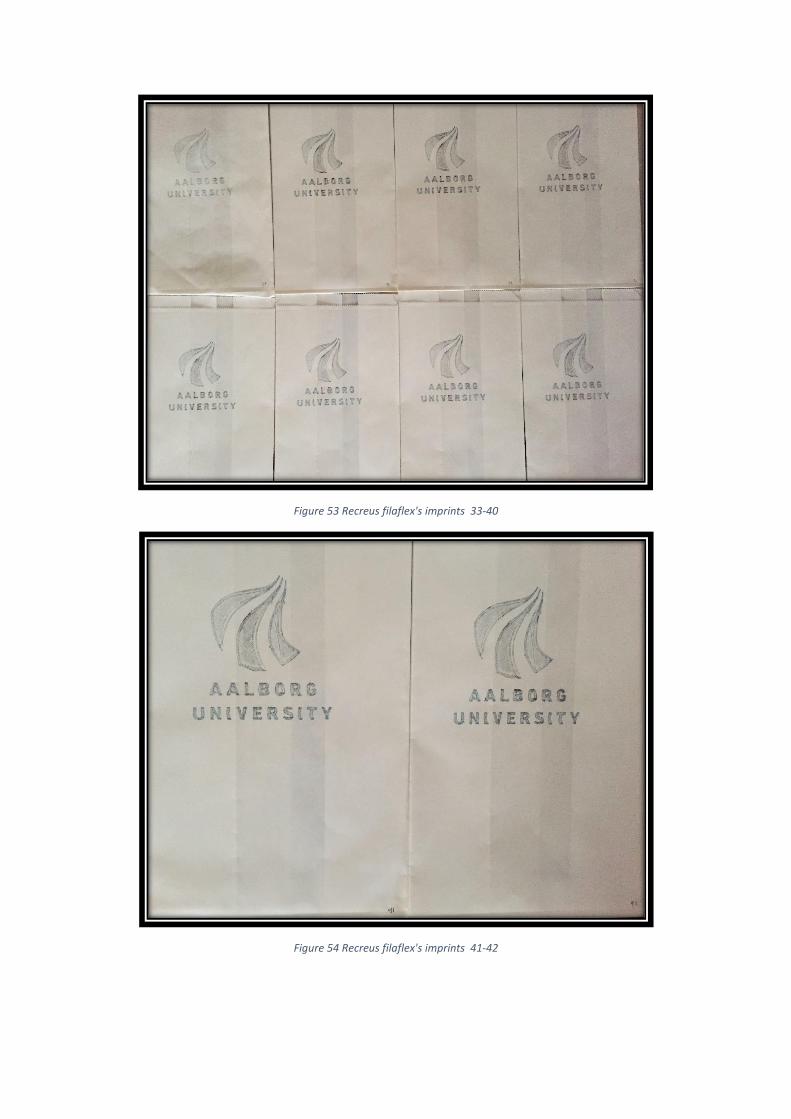
Figure 53 Recreus filaflex's imprints 33-40
Figure 54 Recreus filaflex's imprints 41-42
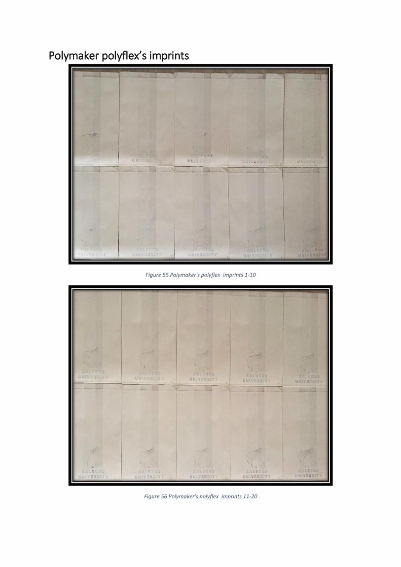
Polymaker polyflex’s imprints
Figure 55 Polymaker's polyflex imprints 1-10
Figure 56 Polymaker's polyflex imprints 11-20
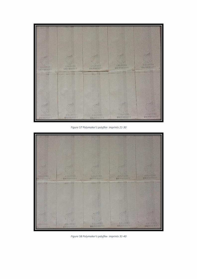
Figure 57 Polymaker's polyflex imprints 21-30
Figure 58 Polymaker's polyflex imprints 31-40
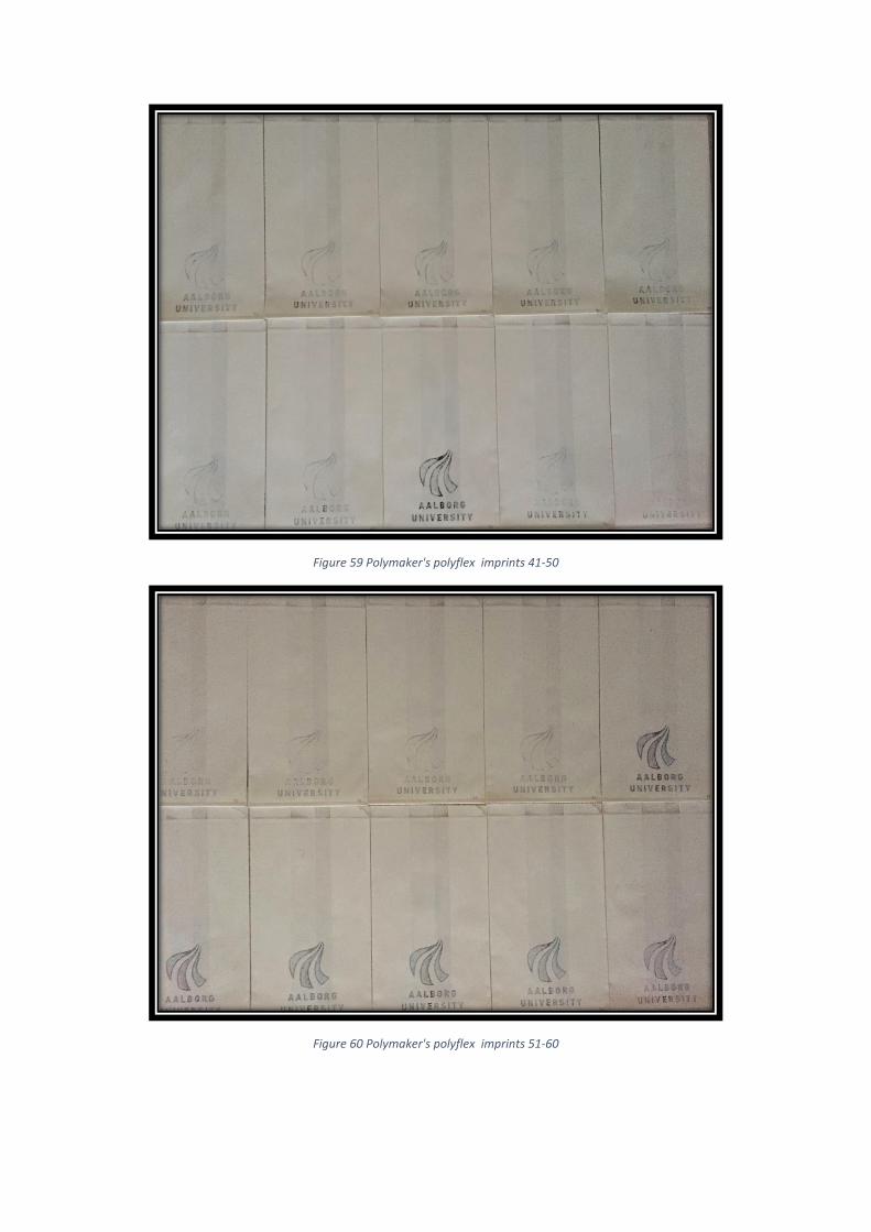
Figure 59 Polymaker's polyflex imprints 41-50
Figure 60 Polymaker's polyflex imprints 51-60
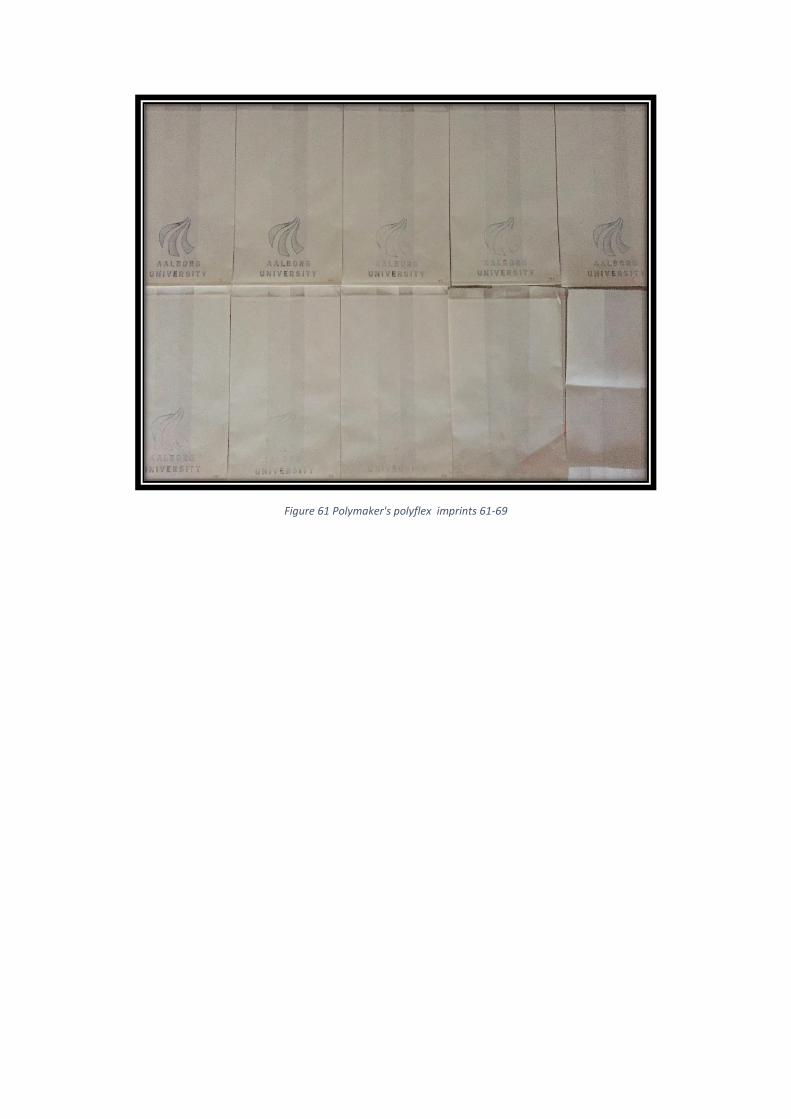
Figure 61 Polymaker's polyflex imprints 61-69

Appendix C, experiment’s detailed data
paper bags printed identification number 3DFlexo-plate Speed visual quality check
1
Rec
reu
s fi
lafl
ex
1 very low
2 2 very low
3 2 low
4 2 low
5 2 low
6 2 low
7 2 low
8 2 low
9 2 low
10 2 acceptable
11 2 acceptable
12 2 acceptable
13 2 acceptable
14 2 acceptable
15 2 acceptable
16 2 acceptable
17 2 acceptable
18 2 acceptable
19 2 acceptable
20 2 acceptable
21 2 acceptable
22 2 acceptable
23 2 acceptable
24 2 acceptable
25 2 acceptable
26 2 acceptable
27 2 acceptable
28 2 acceptable
29 2 acceptable
30 2 acceptable
31 2 acceptable
32 2 acceptable
33 2 acceptable
34 2 acceptable
35 2 acceptable
36 2 acceptable
37 2 acceptable
38 2 acceptable
39 2 acceptable
40 2 acceptable
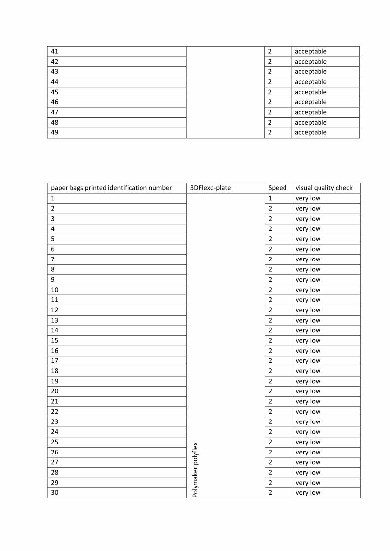
41 2 acceptable
42 2 acceptable
43 2 acceptable
44 2 acceptable
45 2 acceptable
46 2 acceptable
47 2 acceptable
48 2 acceptable
49 2 acceptable
paper bags printed identification number 3DFlexo-plate Speed visual quality check
1 P
oly
mak
er p
oly
flex
1 very low
2 2 very low
3 2 very low
4 2 very low
5 2 very low
6 2 very low
7 2 very low
8 2 very low
9 2 very low
10 2 very low
11 2 very low
12 2 very low
13 2 very low
14 2 very low
15 2 very low
16 2 very low
17 2 very low
18 2 very low
19 2 very low
20 2 very low
21 2 very low
22 2 very low
23 2 very low
24 2 very low
25 2 very low
26 2 very low
27 2 very low
28 2 very low
29 2 very low
30 2 very low
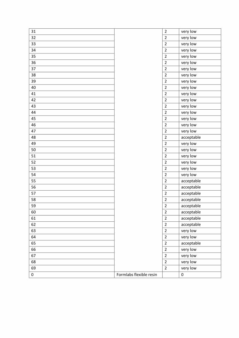
31 2 very low
32 2 very low
33 2 very low
34 2 very low
35 2 very low
36 2 very low
37 2 very low
38 2 very low
39 2 very low
40 2 very low
41 2 very low
42 2 very low
43 2 very low
44 2 very low
45 2 very low
46 2 very low
47 2 very low
48 2 acceptable
49 2 very low
50 2 very low
51 2 very low
52 2 very low
53 2 very low
54 2 very low
55 2 acceptable
56 2 acceptable
57 2 acceptable
58 2 acceptable
59 2 acceptable
60 2 acceptable
61 2 acceptable
62 2 acceptable
63 2 very low
64 2 very low
65 2 acceptable
66 2 very low
67 2 very low
68 2 very low
69 2 very low
0 Formlabs flexible resin
0
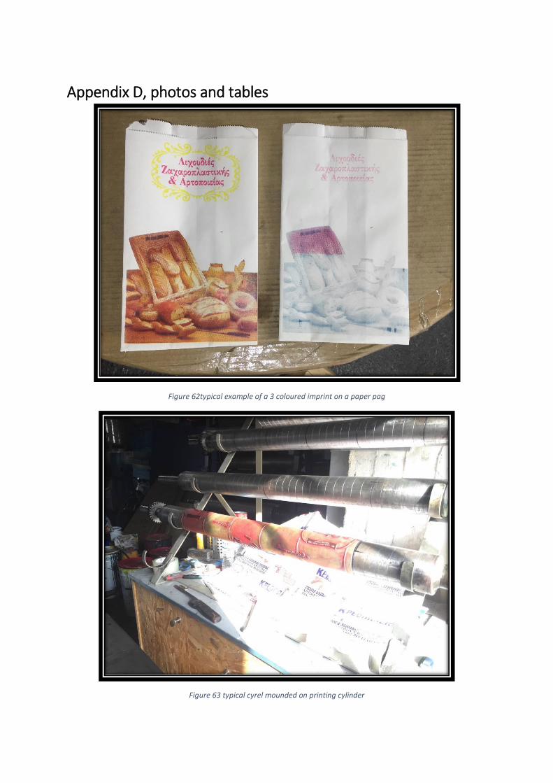
Appendix D, photos and tables
Figure 62typical example of a 3 coloured imprint on a paper pag
Figure 63 typical cyrel mounded on printing cylinder
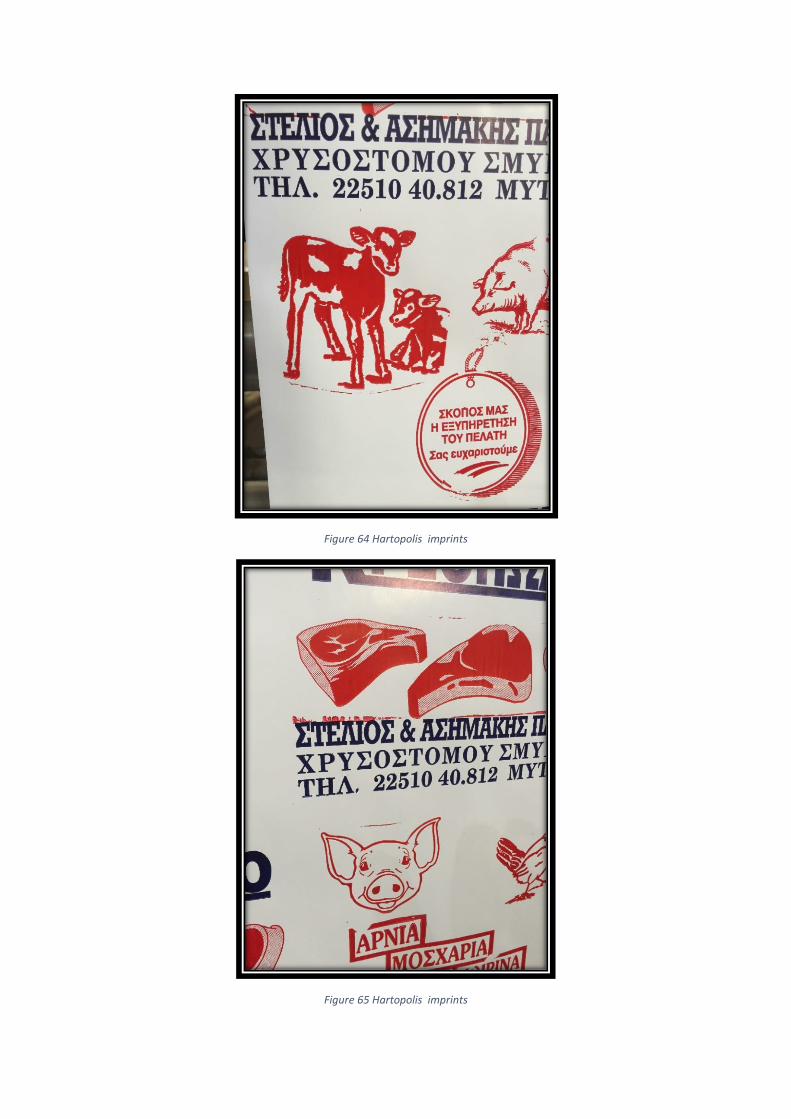
Figure 64 Hartopolis imprints
Figure 65 Hartopolis imprints
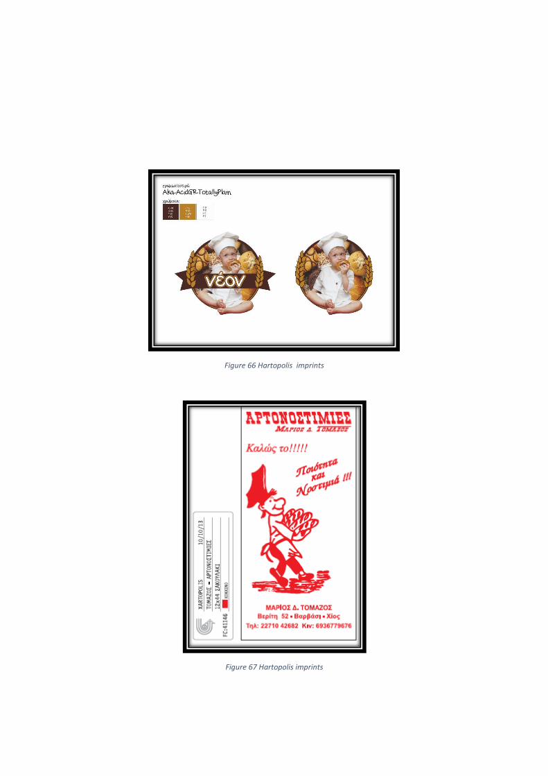
Figure 66 Hartopolis imprints
Figure 67 Hartopolis imprints
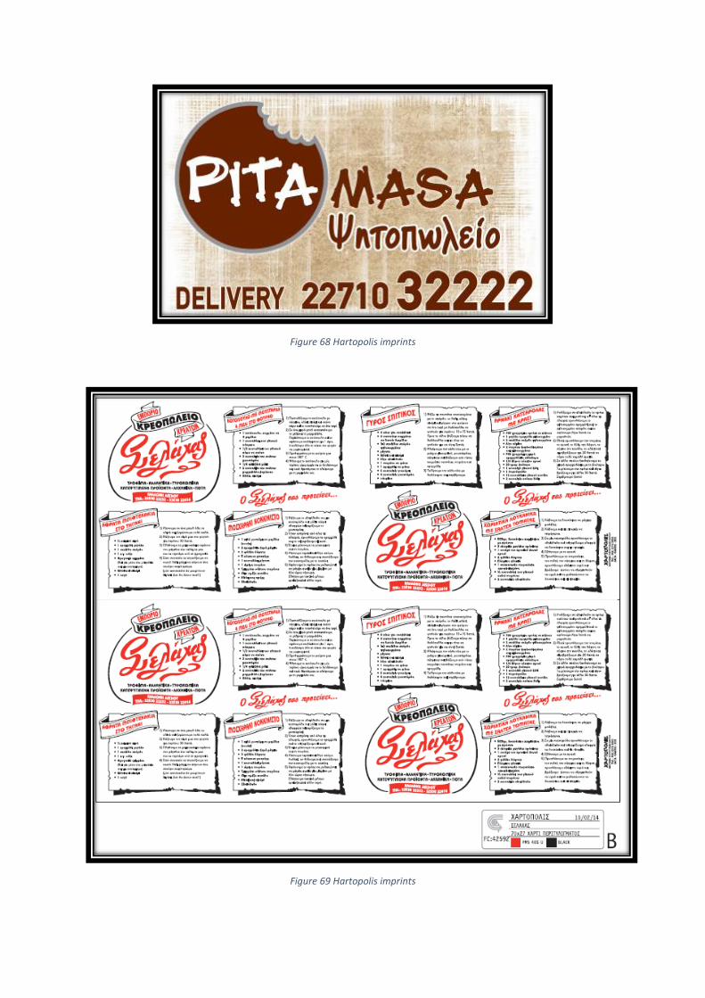
Figure 68 Hartopolis imprints
Figure 69 Hartopolis imprints

Figure 70 Hartopolis imprints, 3 colours
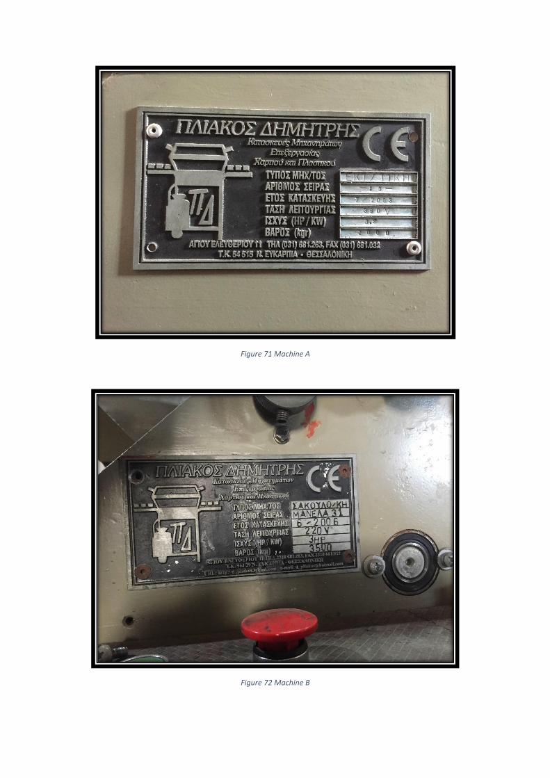
Figure 71 Machine A
Figure 72 Machine B
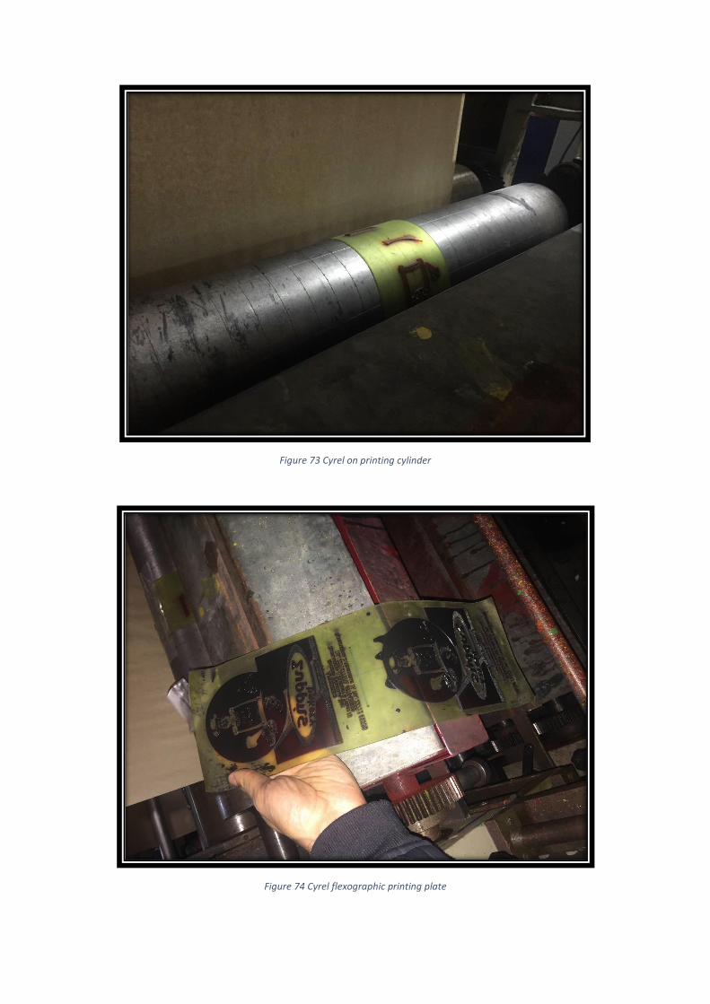
Figure 73 Cyrel on printing cylinder
Figure 74 Cyrel flexographic printing plate
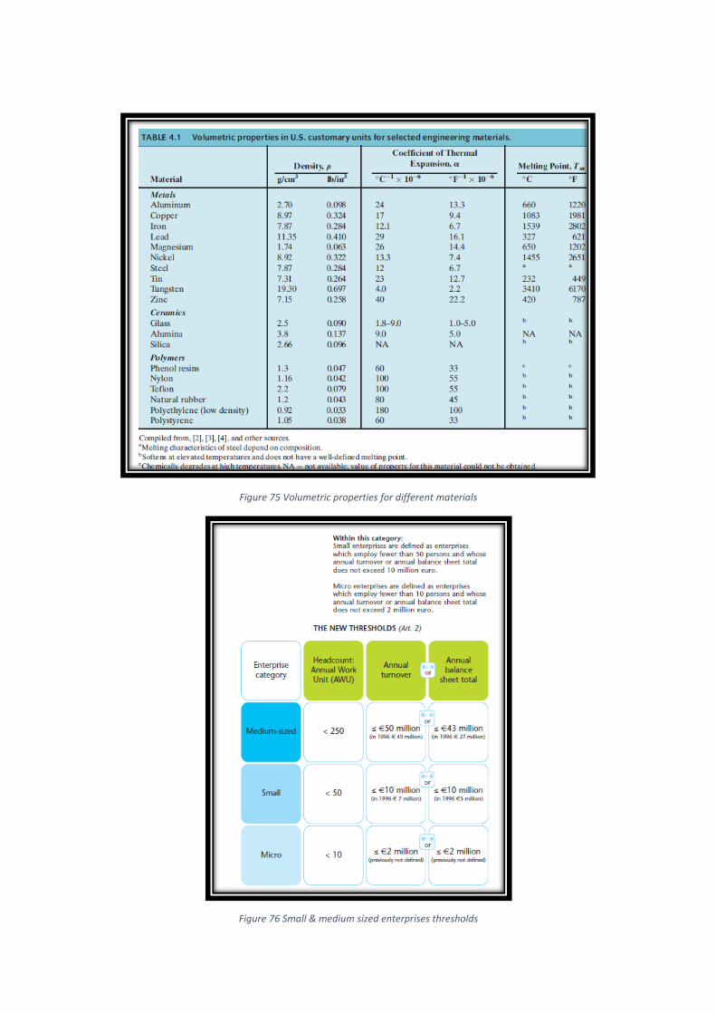
Figure 75 Volumetric properties for different materials
Figure 76 Small & medium sized enterprises thresholds
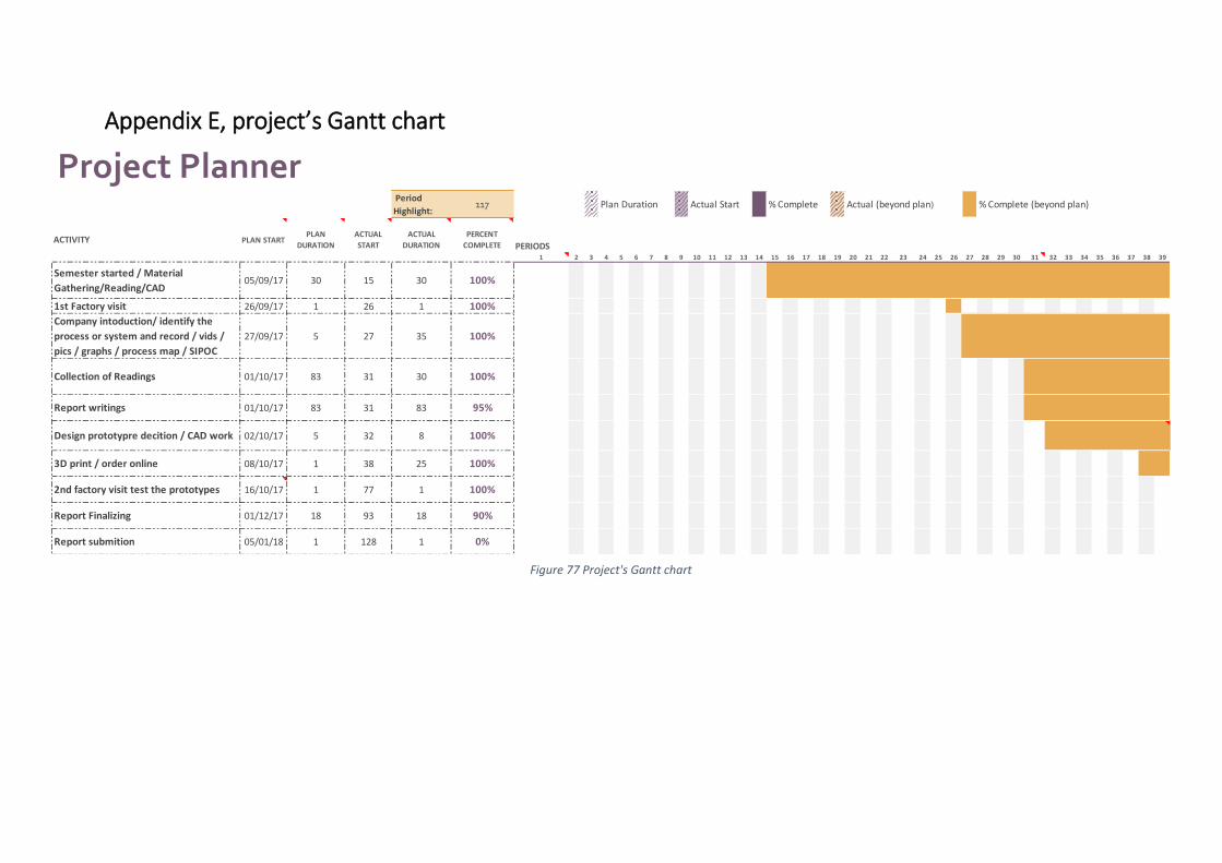
Appendix E, project’s Gantt chart
Project Planner Period
Highlight:117
PERIODS1 2 3 4 5 6 7 8 9 10 11 12 13 14 15 16 17 18 19 20 21 22 23 24 25 26 27 28 29 30 31 32 33 34 35 36 37 38 39
Semester started / Material
Gathering/Reading/CAD05/09/17 30 15 30 100%
1st Factory visit 26/09/17 1 26 1 100%
Company intoduction/ identify the
process or system and record / vids /
pics / graphs / process map / SIPOC
27/09/17 5 27 35 100%
Collection of Readings 01/10/17 83 31 30 100%
Report writings 01/10/17 83 31 83 95%
Design prototypre decition / CAD work 02/10/17 5 32 8 100%
3D print / order online 08/10/17 1 38 25 100%
2nd factory visit test the prototypes 16/10/17 1 77 1 100%
Report Finalizing 01/12/17 18 93 18 90%
Report submition 05/01/18 1 128 1 0%
% Complete (beyond plan)
ACTIVITY PLAN STARTPLAN
DURATION
ACTUAL
START
ACTUAL
DURATION
PERCENT
COMPLETE
Plan Duration Actual Start % Complete Actual (beyond plan)
Figure 77 Project's Gantt chart
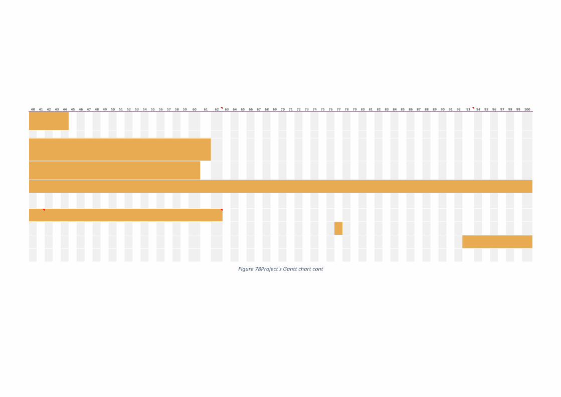
40 41 42 43 44 45 46 47 48 49 50 51 52 53 54 55 56 57 58 59 60 61 62 63 64 65 66 67 68 69 70 71 72 73 74 75 76 77 78 79 80 81 82 83 84 85 86 87 88 89 90 91 92 93 94 95 96 97 98 99 100
Figure 78Project's Gantt chart cont
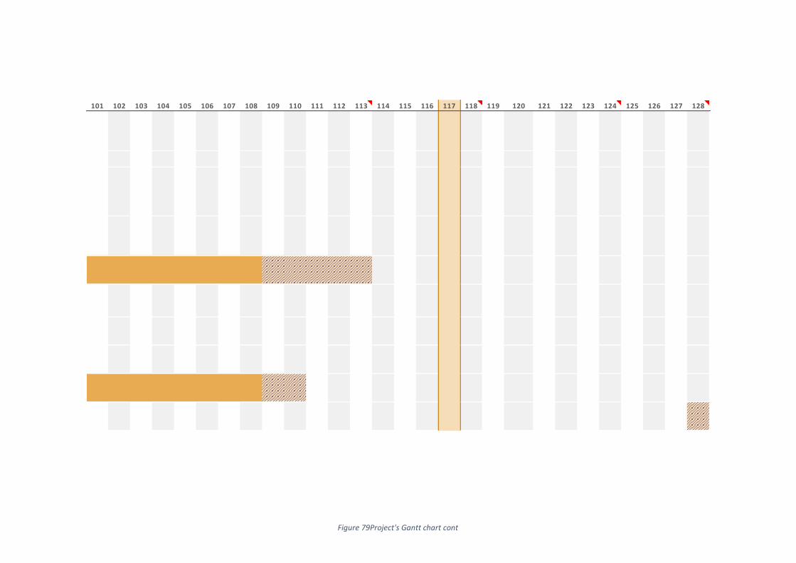
101 102 103 104 105 106 107 108 109 110 111 112 113 114 115 116 117 118 119 120 121 122 123 124 125 126 127 128
Figure 79Project's Gantt chart cont