Embed Size (px)
Citation preview
Scientia et Technica Año XXV, Vol. 25, No. 04, diciembre de 2020. Universidad Tecnológica de Pereira. ISSN 0122-1701 y ISSN-e: 2344-7214
498
Abstract— This article presents the implementation of a 3.5 kW
resistive load bank applied to a four-stroke single-cylinder diesel
engine test bench that operates with an alternator. With this
experimental test bench, it is possible to perform mechanical,
thermodynamic, and polluting emissions studies in compression-
ignited or induced internal combustion engines. Applying the
quantitative research methodology, the design of the electric
charging system is carried out. Power control circuits and safety
elements are designed for the load back. CAD software is used to
design the structure and casing considering anthropometric
measurements. Also, finite element analysis (FEA) is incorporated
to verify the structural and thermal design criteria. he
implementation of an electrical and instrumentation acceleration
system for sensing power and torque in low-displacement engines
showed a measurement error of less than 1%. Similarly, the FEA
allowed to quantify the maximum efforts and guarantee a safety
factor above 5. With the characterization of the implemented
sensors, a correlation coefficient of up to 99.97% was achieved.
The power measurement displayed an error lower than 3%, which
leads to a high characterization capacity of any thermal machine
with equal power or less than the designed one.
Index Terms— Characterization, Engine, Finite elements,
Resistive load bank, Power, and torque sensors.
Resumen— En este artículo se presenta la implementación de un
banco de carga resistivo de 3.5 kW aplicado a un banco de prueba
de motor Diesel monocilíndrico cuatro tiempos acoplado a un
alternador. Con este banco de prueba experimental, es posible
realizar el estudio mecánico, termodinámico y de emisiones
contaminantes en motores de combustión interna de encendido
por compresión o provocado. Aplicando la metodología de
investigación cuantitativa se lleva a cabo el diseño del sistema de
carga eléctrico, y los circuitos de control de potencia con sus
elementos de seguridad, y mediante un software CAD se crea la
estructura y carcasa basados en medidas antropométricas,
aplicándole un estudio de esfuerzo mecánico sobre las piezas
This manuscript was sent on August 31, 2019 and accepted on November 23, 2020.
Miguel Celis Quintero is with Universidad del Atlántico. Mechanical
Engineering Program. Puerto Colombia, Colombia (e-mail: [email protected]).
Gabriel Hernández Acosta is with Universidad del Atlántico. Mechanical
Engineering Program. Puerto Colombia, Colombia (e-mail: [email protected]).
diseñadas a través de un análisis de elementos finitos (AEF). Se
detalla el desarrollo de un sistema de aceleración eléctrico y de
instrumentación para el sensado de potencia y torque en motores
de baja cilindrada, con un error de medición menor al 1%. De
igual forma, el AFE permitió cuantificar los esfuerzos máximos y
garantizar un factor de seguridad por encima de 5. Con la
caracterización de los sensores implementados, se logró un
coeficiente de correlación de hasta 99.97%, y en la medida de
potencia un error inferior al 3%, lo que conlleva a una alta
capacidad de caracterización de cualquier máquina térmica con
una potencia igual o menor a la de diseño.
Palabras claves— Banco de carga resistivo, Caracterización,
Elementos Finitos, Motor, Sensores de potencia y torque.
I. INTRODUCTION
ENSET engines are extensively implemented for electric
power generation, especially for non-interconnected areas.
This technology is becoming of increasing interest due to the
imminent necessity to reduce fuel consumption while
maintaining optimal thermo-mechanical performance [1].
Specifically, energy fluctuations account for a significant
reduction in the overall efficiency. Hence, different
experimental assessments center on the characterization of the
operating load by incorporating a so-called load bank. The latter
is a piece of equipment that emulates the load experienced by
the Genset using electrical charge blocks. This analysis takes
relevance since it stands as a robust tool to evaluate the overall
behavior of Gensets based on the operating load, which further
contributes to set up maintenance actions and evaluate system
improvements [2], [3].
In this sense, a motor-generator set can be implemented as a
didactic way to investigate the main features of operation in an
engine test bench. Internal combustion engines (ICE) convert
chemical energy into mechanical power through a combustion
process. The load condition is determined by the energy
Jorge Duarte Forero is with Universidad del Atlántico. Mechanical Engineering Program. Puerto Colombia, Colombia (e-mail:
Implementation of a 3.5 kW resistive load bank
for a single-cylinder diesel engine test bench
M. Celis-Quintero ; G. Hernández-Acosta ; J. Duarte-Forero
DOI: https://doi.org/10.22517/23447214.22881 Artículo de investigación científica y tecnológica.
Implementación de un banco de carga resistivo de 3.5 kW para un banco de prueba
de motor Diésel monocilíndrico
G
Scientia et Technica Año XXV, Vol. 25, No. 04, diciembre de 2020. Universidad Tecnológica de Pereira
499
demand that the Genet should provide that, in other words, can
be expressed as the required force that needs to be generated
from combustion. The load condition becomes vital since it
determines, to a great extent, the fuel consumption and the
thermo-mechanical behavior of the engine [4]-[6].
Additionally, implementing a load bank allows evaluating the
influence of the load rate on the feasibility of partial fuel
substitution technologies such as biofuel blends and hydrogen
enrichment [7],[8]. Most of the studies regarding the
experimental test bench of diesel engines rarely characterized
the construction and implementation of the load bank, despite
being important equipment of the experimental layout. Also,
the instrumentation and control features remain unexplored.
This investigation is driven to fill the knowledge gap about this
matter by incorporating detailed criteria for structural design as
well as instrumentation and control strategies.
Specifically, a load bank for alternating current (AC) power
tests can be divided into resistive and reactive. Also, the
combination of the last two can be implemented in a test bench.
Taking into account that the power factor is a direct measure of
the fuel conversion efficiency, it should be noted that the
reactive loads lead to a decrease in the power factor [9]-[11].
On the other hand, resistive banks highlights for consuming
active power, which is independent of the electric frequency.
The latter is a significant advantage of this type of load bank
since it maintains a unit power factor [12]-[14]. In a Genset, the
frequency of the voltage delivered to the system is directly
related to the rotational speed of the engine and the number of
poles of the generator. Therefore, when the electromagnetic
torque increases, it produces a reduction of the rotational speed
of the engine, which leads to frequency fluctuations. To
maintain the aforementioned condition within limits, it is
necessary to control the power generated and the electric charge
demand [15]-[17]. Thus, it is evident that the construction of a
load bank requires a major effort to enable control on the
operating conditions of the engine tested, whereas other
important features such as compactness, safeness, and
reliability should be met to provide robust equipment that
facilitates research in ICEs.
This investigation presents the main features of the
construction and implementation of a load bank as didactic and
functional equipment that reinforce experimental testing in
diesel engines. The incorporation of CFD tools to evaluate both
thermal and structural characteristic of the proposal stand as
differential factors from former research. Thus, this work
contributes to close the knowledge gap regarding the
construction criteria of load banks for integration in an
experimental engine setup.
II. RESISTIVE LOAD BANK TESTING DESIGN
For the design of the equipment, the internal elements are
sized before construction to estimate the structural
requirements.
A. Design of the resistive load system
The following limitations are considered for the design of the
resistive load:
Total load: the maximum electric power delivered by
the engine test bench is set as the reference. It is worth
mentioning that the device must work with two
identical engine test benches simultaneously.
Ability to modulate the load: divide the total load into
smaller packages.
Operating temperature: the temperature of the resistive
assembly must guarantee safe operation.
The main characteristics and electrical parameters of the
Genset are specified in Table I.
TABLE I
GENSET ELECTRICAL PARAMETERS.
Variable Magnitude Unit
Max power 3500 W
Nominal Voltage 120/240 VAC
Maximum Intensity 29.2 A
Ohm's law is the total resistance that the load circuit must-
have (Eq. 1).
R =V
I=
120
29.2= 4.109 (1)
The total resistance is rounded to 4 ohms in order to simplify
the calculations. There are several types of resistance in the
market, but a multi-criteria evaluation is done between two
types of most common resistance. According to the multi-
criteria assessment, the resistance that best meets the
requirements is the 30 cm cartridge resistance with ½ in. A
parallel circuit is then configured such that small load packages
can be joined until the desired power consumption is reached as
shown in Table II.
TABLE II
DETERMINATION OF ELECTRICAL PARAMETERS FOR CIRCUIT
CONFIGURATION.
Tension (VAC) Intensity (A) Resistance (Ω)
120 2.82 42.5
Package Equivalent
(A) (W) (Ω)
1 2.82 337.98 42.50
2 5.64 675.95 21.31
3 8.46 1013.93 14.21
4 11.28 1351.91 10.62
5 14.1 1689.89 8.52
6 16.92 2027.86 7.13
7 19.74 2365.84 6.12
8 22.56 2703.82 5.32
9 28.2 3379.77 4.34
10 33.84 4055.72 3.53
Scientia et Technica Año XXV, Vol. 25, No. 04, diciembre de 2020. Universidad Tecnológica de Pereira. ISSN 0122-1701 y ISSN-e: 2344-7214
500
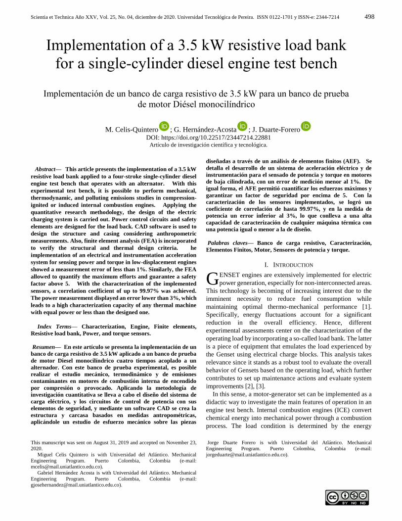
According to the size of the resistances and the tube bank
configuration requirement, a rectangular duct is designed in a
22-gauge galvanized steel sheet. The material is not affected by
the temperature of the resistances since it is isolated internally
with refractory ceramic plates. The final assembly is presented
in Fig. 1.
Fig. 1. Schematic representation of the resistive load duct.
A fan is selected as the cooling mechanism, which operates
by enabling airflow to the resistive load duct, thus maintaining
a safe temperature and avoiding the concentration of heat inside
the system. Axial fans provide different advantages such as
high flow rates at low pressures, reduced size, lower energy
consumption, and low noise, which make them suitable for
cooling the resistive load. An axial fan is selected according to
the available space and the availability in the market, and
subsequently, the thermal analysis is performed to determine
that it meets the requirements (Table III).
TABLE III
CHARACTERISTICS OF THE SELECTED FAN.
VA07-AP12/C-31S
Type Soffiante - Blowing
Propeller Diameter|| 225mm
Tension 12v DC
Static pressure 17.5 mm H2O
Intensity 6.6 A
Airflow 1000 m3/h
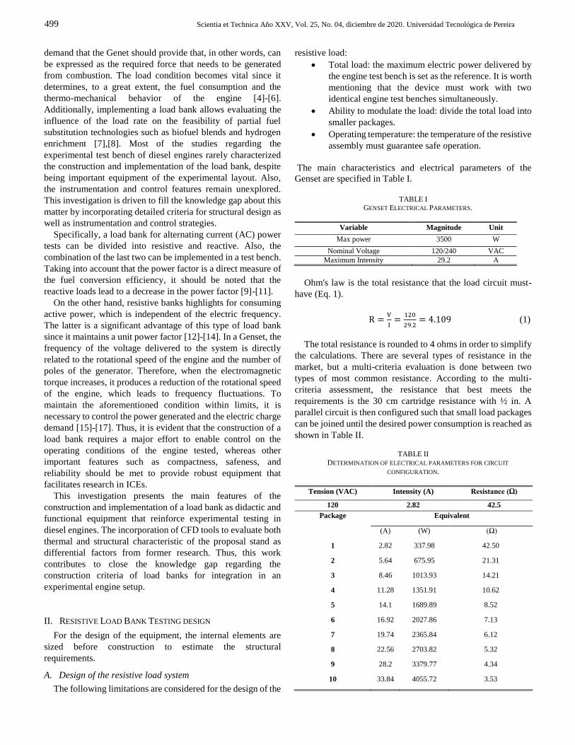
Thermal analysis is performed in order to ensure sufficient
heat transfer with the mass flow provided by the fans. For this
analysis, the maximum power at which the bank can operate is
considered. A surface temperature of the resistances and steady-
state conditions are assumed. The effects of radiation are
neglected. Accordingly, Table IV summarized the operational
conditions of the thermal analysis, and Fig. 2 displays the CFD
simulation results. TABLE IV
GEOMETRIC PROPERTIES OF THE HEATING ELEMENT AND TUBE BANK.
Variable Value Symbol Unit
Temp. superficial assumed 380 Ts °C
Temp. bank entrance 30 Ti °C
Temp. movie stockin|g 50 Tm °C
Input flow rate 2.49 V m⁄s
Outlet temperature 76.87 Te
Total surface area 0.34 Ast m2
Reason for heat transfer 7.39 x10³ Q W
Resistance heat transfer reason 7.20 x 10³ QR W
Error rate 2.64 ER %
Pressure drop 13.21 ∆P Pa
Static Fan Pressure 24.52 Ps Pa
According to the results, the mass flow provided by the fans
maintained a maximum surface temperature of the resistive
elements of 76 °C, which guarantees their integrity. Thermal
flow simulation provides valuable information about the
temperature gradients in the equipment.
Fig. 2. CFD simulation of the load duct - top view.
B. Power control circuit
The design of this circuit includes all the necessary elements
to ensure the secure handling of the electric fluid that comes
from the GE alternator. The power control circuit has two
operation modes to account for changes in the power required
by the load bank, making the device didactic.
The first operation mode corresponds to the stepped power
control that allows power variations in so-called steps, meaning
adding load packages. The second mode is the gradual control,
which enables power variations by the phase control of the
electronic circuit that operates with the delay angle time of the
AC wave propagation. Fig. 3 displays a basic scheme of the
general circuit for power control.
Fig. 3. Scheme of the power control circuit.Load bank instrumentation system
Scientia et Technica Año XXV, Vol. 25, No. 04, diciembre de 2020. Universidad Tecnológica de Pereira
501
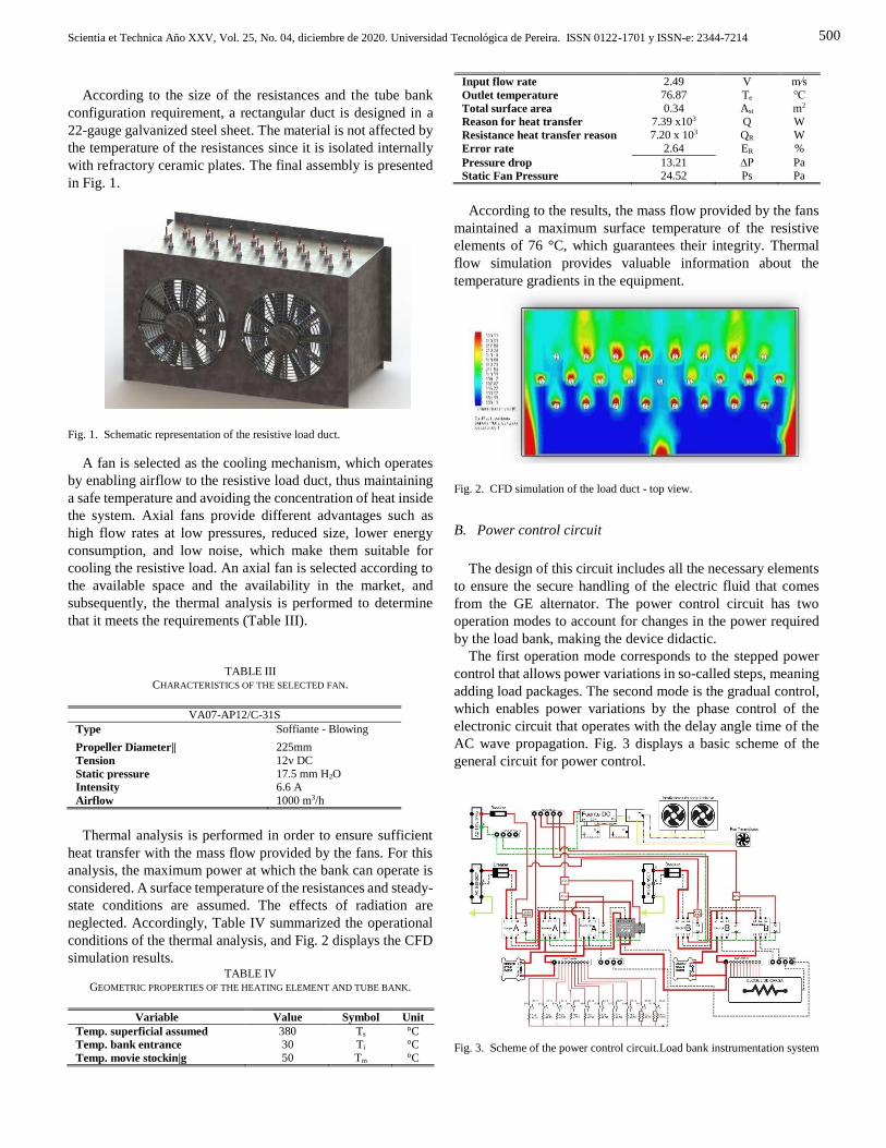
The load bank instrumentation enables data acquisition of
engine parameters such as torque and power. Taking into
account that the power factor is unitary, a device is designed to
measure the electrical power, which adjusts to the mechanical
power using the engine’s efficiency. This device consists of a
non-invasive inductive current transformer that operates on the
Faraday induction principle, sending a low AC signal to a signal
conditioning circuit that rectifies it by converting it into DC
(direct current). This signal is read by an Arduino® data
acquisition card (DAQ) to encode it for signal processing and
finally display the power values on a digital screen.
The signal conditioning circuit is shown in Figure 4.
MC33202 rail-to-rail operational amplifiers are employed since
they are stable and little affected by noise.
Fig. 4. Assembly diagram for power and torque meter.
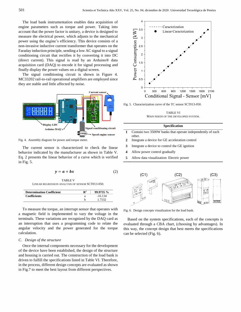
The current sensor is characterized to check the linear
behavior indicated by the manufacturer as shown in Table V.
Eq. 2 presents the linear behavior of a curve which is verified
in Fig. 5.
𝒚 = 𝒂 + 𝒃𝒙 (2)
TABLE V
LINEAR REGRESSION ANALYSIS OF SENSOR SCT013-050.
Determination Coefficient R2 99.9735 %
Coefficients a -16.134
b 1.7532
To measure the torque, an interrupt sensor that operates with
a magnetic field is implemented to vary the voltage in the
terminals. These variations are recognized by the DAQ card as
an interruption that uses a programming code to relate the
angular velocity and the power generated for the torque
calculation.
C. Design of the structure
Once the internal components necessary for the development
of the device have been established, the design of the structure
and housing is carried out. The construction of the load bank is
driven to fulfill the specifications listed in Table VI. Therefore,
in the process, different design concepts are evaluated as shown
in Fig.7 to meet the best layout from different perspectives.
Fig. 5. Characterization curve of the TC sensor SCT013-050.
TABLE VI
MAIN NEEDS OF THE DEVELOPED SYSTEM.
Specification
1 Contain two 3500W banks that operate independently of each
other.
2 Integrate a device for GE acceleration control
3 Integrate a device to control the GE ignition
4 Allow power control gradually
5 Allow data visualization: Electric power
Fig. 6. Design concepts visualization for the load bank.
Based on the system specifications, each of the concepts is
evaluated through a CBA chart, (choosing by advantages). In
this way, the concept design that best meets the specifications
can be selected (Fig. 6).
Scientia et Technica Año XXV, Vol. 25, No. 04, diciembre de 2020. Universidad Tecnológica de Pereira. ISSN 0122-1701 y ISSN-e: 2344-7214
502
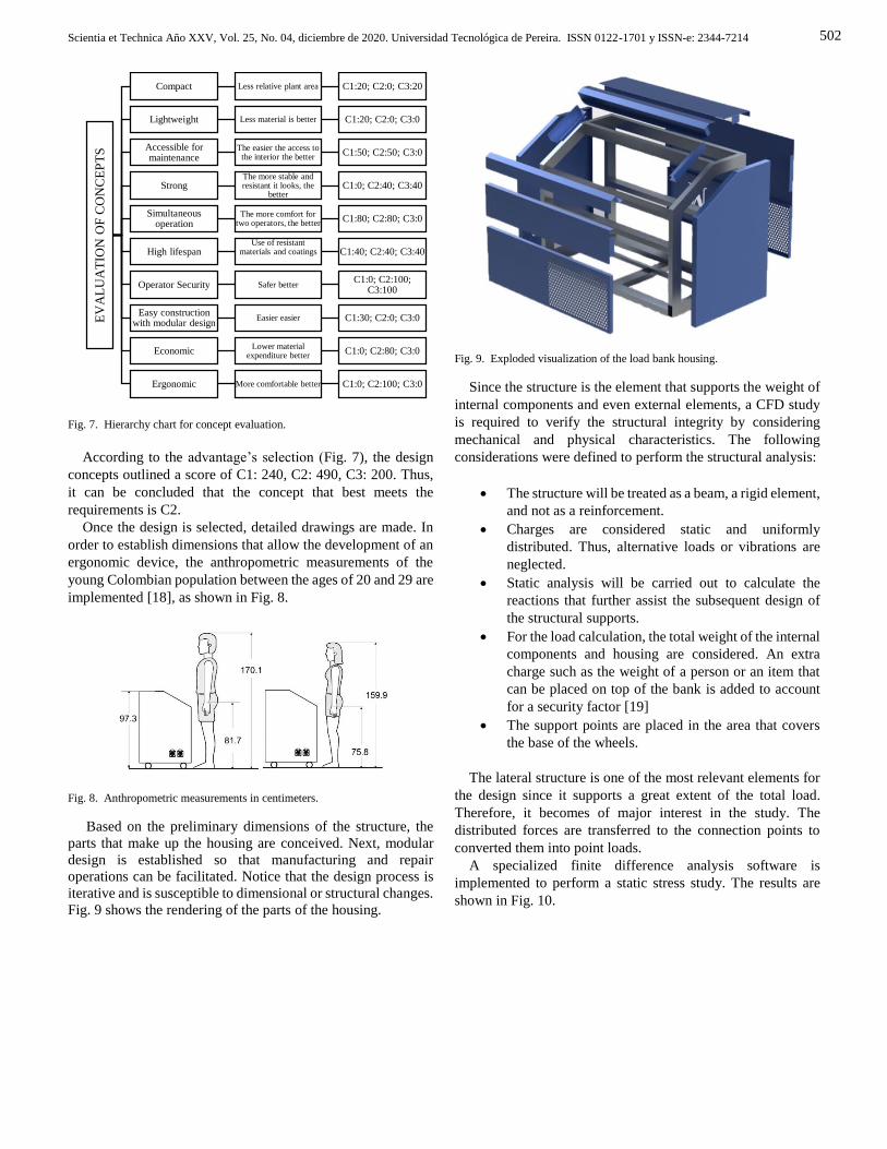
Fig. 7. Hierarchy chart for concept evaluation.
According to the advantage’s selection (Fig. 7), the design
concepts outlined a score of C1: 240, C2: 490, C3: 200. Thus,
it can be concluded that the concept that best meets the
requirements is C2.
Once the design is selected, detailed drawings are made. In
order to establish dimensions that allow the development of an
ergonomic device, the anthropometric measurements of the
young Colombian population between the ages of 20 and 29 are
implemented [18], as shown in Fig. 8.
Fig. 8. Anthropometric measurements in centimeters.
Based on the preliminary dimensions of the structure, the
parts that make up the housing are conceived. Next, modular
design is established so that manufacturing and repair
operations can be facilitated. Notice that the design process is
iterative and is susceptible to dimensional or structural changes.
Fig. 9 shows the rendering of the parts of the housing.
Fig. 9. Exploded visualization of the load bank housing.
Since the structure is the element that supports the weight of
internal components and even external elements, a CFD study
is required to verify the structural integrity by considering
mechanical and physical characteristics. The following
considerations were defined to perform the structural analysis:
The structure will be treated as a beam, a rigid element,
and not as a reinforcement.
Charges are considered static and uniformly
distributed. Thus, alternative loads or vibrations are
neglected.
Static analysis will be carried out to calculate the
reactions that further assist the subsequent design of
the structural supports.
For the load calculation, the total weight of the internal
components and housing are considered. An extra
charge such as the weight of a person or an item that
can be placed on top of the bank is added to account
for a security factor [19]
The support points are placed in the area that covers
the base of the wheels.
The lateral structure is one of the most relevant elements for
the design since it supports a great extent of the total load.
Therefore, it becomes of major interest in the study. The
distributed forces are transferred to the connection points to
converted them into point loads.
A specialized finite difference analysis software is
implemented to perform a static stress study. The results are
shown in Fig. 10.
EV
AL
UA
TIO
N O
F C
ON
CE
PT
SCompact Less relative plant area C1:20; C2:0; C3:20
Lightweight Less material is better C1:20; C2:0; C3:0
Accessible for maintenance
The easier the access to the interior the better
C1:50; C2:50; C3:0
StrongThe more stable and resistant it looks, the
betterC1:0; C2:40; C3:40
Simultaneous operation
The more comfort for two operators, the better
C1:80; C2:80; C3:0
High lifespanUse of resistant
materials and coatings C1:40; C2:40; C3:40
Operator Security Safer betterC1:0; C2:100;
C3:100
Easy construction with modular design
Easier easier C1:30; C2:0; C3:0
EconomicLower material
expenditure betterC1:0; C2:80; C3:0
Ergonomic More comfortable better C1:0; C2:100; C3:0
Scientia et Technica Año XXV, Vol. 25, No. 04, diciembre de 2020. Universidad Tecnológica de Pereira
503
Fig. 10. Analysis of equivalent efforts with finite differences.
According to the results, it can be verified a high safety factor
in the design, which can be explained from an oversized profile
selection. However, based on commercial, aesthetic, and
functional reasons, the body or carcass support required the
selected profile.
D. Control panel design
The main control panel is an important part of the design of
the load bank since it contains all the necessary controls for
device handling. In addition, the panel included diagrams and
necessary indications for didactic purposes that facilitate
understanding and manipulation (Fig. 11). This piece is vital in
the equipment since it communicates with the operator and the
machine. Therefore, it must have a careful design regarding the
location of the controls and quick operation actions in case of
an emergency. The control panel houses the control of two load
banks that, despite being integrated into the same device,
operate independently. The nomenclature of each bank is A and
B, respectively.
Fig. 11. Main control panel of the load bank.
III. TESTS AND DEVELOPMENT
Using the CAD design tool, SolidWorks® renders renderings
on the final design of the bank in order to have a preview of
what the load bank will be, as shown in Fig. 12.
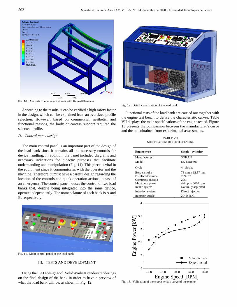
Fig. 12. Detail visualization of the load bank.
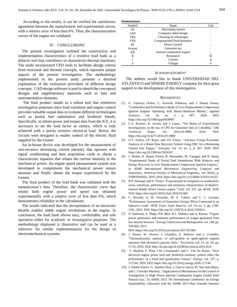
Functional tests of the load bank are carried out together with
the engine test bench to derive the characteristic curves. Table
VII displays the main specifications of the engine tested. Figure
13 presents the comparison between the manufacturer's curve
and the one obtained from experimental assessments.
TABLE VII SPECIFICATIONS OF THE TEST ENGINE
Engine type
Single - cylinder
Manufacturer SOKAN
Model SK-MDF300
Cycle
4 - Stroke
Bore x stroke 78 mm x 62.57 mm
Displaced volume 299 CC
Compression ratio 20:1 Maximum power 4.6 hp to 3600 rpm
Intake system Naturally aspirated
Injection system Direct injection
Injection Angle 20° BTDC
Fig. 13. Validation of the characteristic curve of the engine.
Scientia et Technica Año XXV, Vol. 25, No. 04, diciembre de 2020. Universidad Tecnológica de Pereira. ISSN 0122-1701 y ISSN-e: 2344-7214
504
According to the results, it can be verified the satisfactory
agreement between the manufacturer and experimental curves,
with a relative error of less than 6%. Thus, the characterization
curves of the engine are validated.
IV. CONCLUSIONS
The present investigation outlined the construction and
implementation characteristics of a resistive load bank as a
didactic tool that contributes to characterize thermal machines.
The study incorporated CFD tools to facilitate design criteria
from structural and thermal concepts, which represent unique
aspects of the present investigation. The methodology
implemented in the present study presents a detailed
explanation of the evaluation procedure of different design
concepts. CAD design software is used to sketch the conceptual
designs and supplementary materials such as fans and
instrumentation elements.
The final product stands as a robust tool that reinforces
investigative purposes since load variations and engine control
provides valuable output data to evaluate different technologies
such as partial fuel substitution and biodiesel blends.
Specifically, to obtain power and torque data from the ICE, it is
necessary to set the load factor as unitary, which is only
achieved with a purely resistive electrical load. Hence, the
circuits were designed to enable control of the electric fluid
supplied by the Genset
An in-house device was developed for the measurement of
non-invasive alternating current intensity that operates with
signal conditioning and data acquisition cards to obtain a
characteristic equation that relates the current intensity to the
mechanical power. An engine speed measurement system was
developed to complement the mechanical power sensor
measure and finally obtain the torque experienced by the
Genset.
The final product of the load bank was validated with the
manufacturer´s data. Therefore, the characteristic curve that
relates both engine power and speed was obtained
experimentally with a relative error of less than 6%, which
demonstrates reliability in the calculations.
The results indicated that the incorporation of an electronic
throttle enables stable engine revolutions in the engine. In
conclusion, the load bank allows easy, comfortable, and safe
operation either for academic or investigative purposes. The
methodology displayed is illustrative and can be used as a
reference for similar implementations for the design of
electromechanical systems.
Nomenclature
Symbol Name Unit
AC Alternating current - CAD Computer-aided design - CBA Choosing by advantages - CFD Computational fluid dynamics - DC Direct Current -
Genset Generator set - ICE Internal combustion engine - R Resistance Ω I Current A V Voltage V
ACKNOWLEDGMENT
The authors would like to thank UNIVERSIDAD DEL
ATLÁNTICO and SPHERE ENERGY company for their great
support to the development of this investigation.
REFERENCES
[1] G. Valencia Ochoa, C. Acevedo Peñaloza, and J. Duarte Forero,
“Combustion and Performance Study of Low-Displacement Compression
Ignition Engines Operating with Diesel–Biodiesel Blends,” Applied
Sciences, vol. 10, no. 3, p. 907, 2020. DOI:
https://doi.org/10.3390/app10030907
[2] C.A. Romero, R. Acosta, and J. Lopez, “The Status of Experimental
Investigations on the use of LPG for Generator Sets in Colombia,” SAE
Technical Paper, No. 2016-01-0880, 2016. DOI:
https://doi.org/10.4271/2016-01-0880
[3] G.V. Ochoa, J.P. Rojas, and J.D. Forero, “Advance Exergo-Economic
Analysis of a Waste Heat Recovery System Using ORC for a Bottoming
Natural Gas Engine,” Energies, vol. 13, no. 1, p. 267, 2020. DOI:
https://doi.org/10.3390/en13010267
[4] J. Duarte, N. Duarte Forero, B. Hernandez, M. Vanegas, and R. Stand,
“Experimental Study of Partial Fuel Substitution With Hydroxy and
Energy Recovery in Low Displacement Compression Ignition Engines,”
In ASME International Mechanical Engineering Congress and
Exposition, American Society of Mechanical Engineers, vol. 59452, p.
V008T09A021, 2019. DOI: https://doi.org/10.1115/IMECE2019-10122
[5] D.P. Satsangi, and N. Tiwari, “Experimental investigation on combustion,
noise, vibrations, performance and emissions characteristics of diesel/n-
butanol blends driven Genset engine,” Fuel, vol. 221, pp. 44-60, 2018.
DOI: https://doi.org/10.1016/j.fuel.2018.02.060
[6] C. Ricardo, A. M. Fernando, M. P. Valmir, and C. L. Luciana,
“Performance Assessment of Generators Groups When Connected to an
Inductive Load,” IEEE Trans. Latin America, vol. 14, no. 3, pp. 1296-
1301, 2016. DOI: https://doi.org/10.1109/TLA.2016.7459612
[7] N. Indrawan, S. Thapa, P.R. Bhoi, R.L. Huhnke, and A. Kumar, “Engine
power generation and emission performance of syngas generated from
low-density biomass,” Energy Conversion and Management, vol. 148, pp.
593-603, 2017.
DOI: https://doi.org/10.1016/j.enconman.2017.05.066
[8] J. Duarte, W. Orozco, J. González, E. Buelvas, and L. Corredor,
“Thermodynamic analysis of self-ignition in spark-ignited engines
operated with alternative gaseous fuels,” Tecciencia, vol. 11, no. 20, pp.
57-65, 2016. DOI: http://dx.doi.org/10.18180/tecciencia.2016.20.8.
[9] V. Huchon, F. Pinta, J.M. Commandré, and L. Van De Steene, “How
electrical engine power load and feedstock moisture content affect the
performance of a fixed bed gasification Genset,” Energy, vol. 197, p.
117144, 2020. DOI: https://doi.org/10.1016/j.energy.2020.117144
[10] J. Duarte Forero, G. Amador Diaz, J. Garcia Garcia, M. San Juan Mejia,
and L. Corredor Martinez, “Application of Mechanisms for the Control of
Autoignition in High Power Internal Combustion Engine Fueled With
Natural Gas,” In ASME 2013 7th International Conference on Energy
Sustainability collocated with the ASME 2013 Heat Transfer Summer

Scientia et Technica Año XXV, Vol. 25, No. 04, diciembre de 2020. Universidad Tecnológica de Pereira
505
Conference and the ASME 2013 11th International Conference on Fuel
Cell Science, Engineering and Technology. American Society of
Mechanical Engineers Digital Collection, ES2013-18023,
V001T13A0022013. DOI: https://doi.org/10.1115/ES2013-18023
[11] J.E.D. Forero, W.G. Estrada, and J.S. Guerrero, “Desarrollo de una
metodología para la predicción del volumen real en la cámara de
combustión de motores diésel utilizando elementos finitos,” INGECUC,
vol. 14, no. 1, pp. 122-132, 2018. DOI:
https://doi.org/10.17981/ingecuc.14.1.2018.11.
[12] H.N. Pallares, S.V. Acosta, J.E.D. Forero, and A.R. Montenegro,
“Implementación de un banco para pruebas en motor Diésel
monocilíndrico con aplicaciones investigativas,” Scientia et technica, vol.
22, no. 4, pp. 330-340, 2017. DOI:
http://dx.doi.org/10.22517/23447214.16111
[13] M. B. Freddy y R. T. Miller, “Diseño y construcción de un banco de
pruebas para motores mono cilíndricos de cuatro tiempos a gasolina,”
Trabajo de grado, Facultad de Ing. Mecánica, Escuela de ingeniería y
administración, Universidad Pontificia Bolivariana, Bucaramanga,
Colombia, Jun. 2011.
[14] G. V. Ochoa, C. Isaza-Roldan, and J.D. Forero, “A phenomenological
base semi-physical thermodynamic model for the cylinder and exhaust
manifold of a natural gas 2-megawatt four-stroke internal combustion
engine,” Heliyon, vol. 5, no. 10, e02700, 2019. DOI:
https://doi.org/10.1016/j.heliyon.2019.e02700
[15] R. Ramírez, A.S. Gutiérrez, J.J.C. Eras, K. Valencia, B. Hernández, and
J.D. Forero, “Evaluation of the energy recovery potential of
thermoelectric generators in diesel engines,” Journal of Cleaner
Production, vol. 241, p. 118412, 2019. DOI:
https://doi.org/10.1016/j.jclepro.2019.118412
[16] G. Valencia Ochoa, C. Acevedo Peñaloza, and J. Duarte Forero,
“Thermoeconomic optimization with PSO Algorithm of waste heat
recovery systems based on Organic Rankine Cycle system for a natural
gas engine,” Energies, vol. 12, no. 21, p. 4165, 2019. DOI:
https://doi.org/10.3390/en12214165
[17] A.K. Agarwal, N. Sharma, A.P. Singh, V. Kumar, D.P. Satsangi, and C.
Patel, “Adaptation of Methanol–Dodecanol–Diesel Blend in Diesel
Genset Engine,” Journal of Energy Resources Technology, vol. 141, no.
10, p. 102203, 2019. DOI: https://doi.org/10.1115/1.4043390
[18] C. A. Rosalío, L. P. Lilia y M. G. Elvia, “Dimensiones antropométricas
de población colombiana,” Dimensiones antropométricas de población
latinoamerica, 2ª ed. México: Univ. de Guadalajara, 2007, pp. 197-204.
ISBN 978-970-27-1193-3
[19] Extrudal S.A. (2016, Febrero), “Catalogo de extrusiones de aluminio,”
Formas y dimensiones normalizadas. [En línea]. Disponible:
http://extrudal.com/cat1.pdf
Miguel Celis Quintero. Barranquilla
native, Received a degree in Mechanical
Engineering from Universidad Del
Atlántico, located in Barranquilla,
Colombia in 2018.
ORCID: https://orcid.org/0000-0001-
6776-8899
Gabriel Hernández Acosta. Barranquilla
native, Received a degree in Mechanical
Engineering from Universidad Del
Atlántico, located in Barranquilla,
Colombia in 2018.
ORCID: https://orcid.org/0000-0002-7848-
8638
Jorge Duarte Forero. Barranquilla
native, Colombia. He is an associated
professor of the Mechanical Engineering
Program at Universidad del Atlántico. He
received his BSME from Universidad del
Atlántico, located in Barranquilla,
Colombia in 2007. Master in Mechanical
Engineering from Universidad del Norte,
Barranquilla, Colombia in 2013. Ph. D in
Engineering from Universidad del Norte, Colombia in 2017. He
is a COLCIENCIAS – Senior Researcher.
ORCID: https://orcid.org/0000-0001-7345-9590