Embed Size (px)
Citation preview
Implementation of a MPPT Neural Controller for Photovoltaic
Systems on FPGA Circuit
NAOUFEL KHALDI, HASSAN MAHMOUDI, MALIKA ZAZI*, YOUSSEF BARRADI* Mohammedia School of Engineer LEEP, * Higher School of Technical Education LMIP
Mohamed V University Agdal, * Mohamed V University Souissi
Avenue Ibnsina B.P. 765 Agdal, *Avenue des Forces Armées Royales B.P. 6207
Rabat, Morocco
[email protected], [email protected], [email protected], [email protected]
Abstract: - The maximum power point tracking (MPPT) system controls the voltage and the current output of
the photovoltaic (PV) system to deliver maximum power to the load. Parameters values were extracted using
Newton Raphson method from characteristics of Shell SP75 module. This paper presents a comparative
analysis of incremental conductance (IC), and neural network based MPPT techniques. The Artificial Neural
Network (ANN) method is used to deliver the appropriate duty cycle signal used to drive boost converter to
track the MPP even with variations of the input values using Matlab/Simulink for the simulation and Hardware
Description Language (VHDL) for the implementation on kit Field Programming Gate Array (FPGA) Spartan-
3E of Xilinx.
Key-Words: - Artificial neural network, Photovoltaic systems, Incremental conductance, MPPT, VHDL, FPGA
1 Introduction
Demand for electrical energy has remarkably
increased during the recent years with growing
population and industrial progress. Since long time
ago, fossil fuels have served as the major source of
generating electrical energy. However the transfer of
energy resulting from photovoltaic conversion
remains relatively weak. Therefore, many tracking
control strategies have been proposed in existing
literatures, such as perturb and observe, incremental
conductance, Variable voltage, and fuzzy logic
methods [1,2,14]. But for this work a novel BP
neural networks MPPT algorithm has been used.
These new control techniques feature advantages of
simplicity, high flexibility and less fluctuation
around the maximum power point which increase
efficiency of the PV system [3]. In [4], Newton
Raphson method is used due to the nonlinearity of
Current/Voltage (I-V) characteristics of PV module.
Selection of appropriate converter is also very
important for an efficient PV system [13]. There are
a few topologies can be used with PV system for
load connectivity, among them boost converter has
been selected here due to its available use in
standalone and grid connected PV system and
simultaneous step up capability [5,6]. This paper
results show that the proposed BP MPPT method
can track maximum power point (MPP) in different
temperature and irradiation, which has excellent
output characteristic of high accuracy and good
robustness as compare with method IC.
Experimental results from implementation of a
FPGA allow the validity of the proposed neural
control and deliver the appropriate duty cycle signal
under different values of solar radiation and
temperature as comparing with Matlab/Simulink
simulation.
The sequential work flow of this paper is as
follows: In section 2, complete working procedure
of the system has been described. Section 3 covers
mathematical modelling of PV using a Newton
Raphson method, and followed by discussion on
boost dc-dc converter and MPPT algorithms in
Sections 4 and 5 respectively. Simulation and
experimental works and results are discussed in
Section 6 and 7. Lastly, in section 8, a precise
conclusion has been added to finalize the work.
2 Complete System Overview
A photovoltaic cell is basically a PN
semiconductor junction diode and this cell
converts solar light energy into electricity [7].
WSEAS TRANSACTIONS on POWER SYSTEMSNaoufel Khaldi, Hassan Mahmoudi, Malika Zazi, Youssef Barradi
E-ISSN: 2224-350X 471 Volume 9, 2014
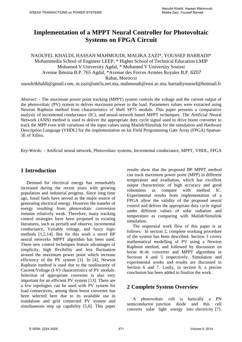
The complete system block diagram is shown in
Fig.1 After that this energy will be supplied to the
load through the buck-boost converter and the
converter will be controlled by a MPPT controller.
T
G
Neural network MPPT
T
G
Fig. 1 Schematic arrangement for the complete
system
3 PV Modelling
3.1 Mathematical Modeling
There are various methods to perform modeling
work on the PV module, and the most of them is
described by using mathematical modeling [8,9].
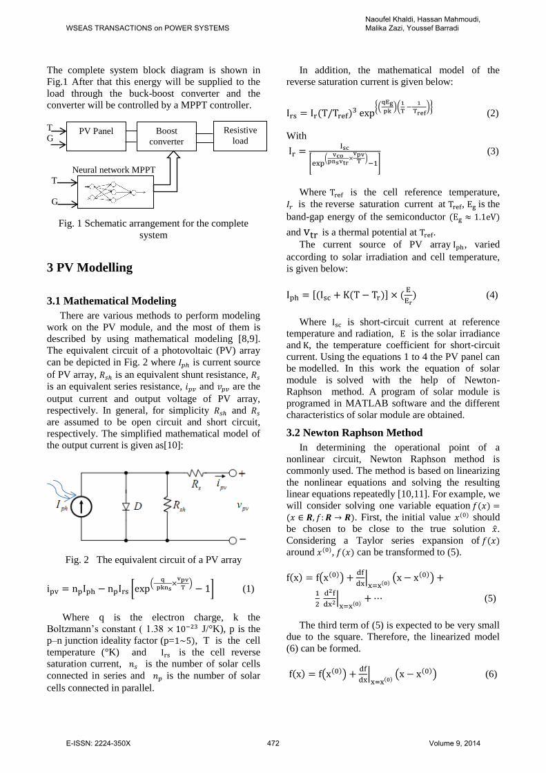
The equivalent circuit of a photovoltaic (PV) array
can be depicted in Fig. 2 where is current source
of PV array, is an equivalent shunt resistance,
is an equivalent series resistance, and are the
output current and output voltage of PV array,
respectively. In general, for simplicity and
are assumed to be open circuit and short circuit,
respectively. The simplified mathematical model of
the output current is given as[10]:
Fig. 2 The equivalent circuit of a PV array
[ (
) ] (1)
Where q is the electron charge, k the
Boltzmann’s constant ( 1.38 J/°K), p is the
p–n junction ideality factor (p= , T is the cell
temperature (°K) and is the cell reverse
saturation current, is the number of solar cells
connected in series and is the number of solar
cells connected in parallel.
In addition, the mathematical model of the
reverse saturation current is given below:
{(
)(
)} (2)
With
[ (
) ]
(3)
Where is the cell reference temperature,
is the reverse saturation current at , is the
band-gap energy of the semiconductor
and is a thermal potential at .
The current source of PV array , varied
according to solar irradiation and cell temperature,
is given below:
[ ]
(4)
Where is short-circuit current at reference
temperature and radiation, is the solar irradiance
and , the temperature coefficient for short-circuit
current. Using the equations 1 to 4 the PV panel can
be modelled. In this work the equation of solar
module is solved with the help of Newton-
Raphson method. A program of solar module is
programed in MATLAB software and the different
characteristics of solar module are obtained.
3.2 Newton Raphson Method
In determining the operational point of a
nonlinear circuit, Newton Raphson method is
commonly used. The method is based on linearizing
the nonlinear equations and solving the resulting
linear equations repeatedly [10,11]. For example, we
will consider solving one variable equation
. First, the initial value should
be chosen to be close to the true solution ̂.
Considering a Taylor series expansion of
around , can be transformed to (5).
( )
|
( )
|
(5)
The third term of (5) is expected to be very small
due to the square. Therefore, the linearized model
(6) can be formed.
( )
|
( ) (6)
PV Panel Boost
converter
Resistive
load
WSEAS TRANSACTIONS on POWER SYSTEMSNaoufel Khaldi, Hassan Mahmoudi, Malika Zazi, Youssef Barradi
E-ISSN: 2224-350X 472 Volume 9, 2014
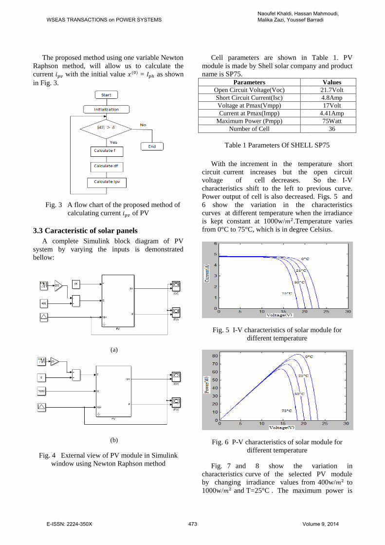
The proposed method using one variable Newton
Raphson method, will allow us to calculate the
current with the initial value = as shown
in Fig. 3.
Fig. 3 A flow chart of the proposed method of
calculating current of PV
3.3 Caracteristic of solar panels
A complete Simulink block diagram of PV
system by varying the inputs is demonstrated
bellow:
(a)
(b)
Fig. 4 External view of PV module in Simulink
window using Newton Raphson method
Cell parameters are shown in Table 1. PV
module is made by Shell solar company and product
name is SP75. Parameters Values
Open Circuit Voltage(Voc) 21.7Volt
Short Circuit Current(Isc) 4.8Amp
Voltage at Pmax(Vmpp) 17Volt
Current at Pmax(Impp) 4.41Amp
Maximum Power (Pmpp) 75Watt
Number of Cell 36
Table 1 Parameters Of SHELL SP75
With the increment in the temperature short
circuit current increases but the open circuit
voltage of cell decreases. So the I-V
characteristics shift to the left to previous curve.
Power output of cell is also decreased. Figs. 5 and
6 show the variation in the characteristics
curves at different temperature when the irradiance
is kept constant at 1000w/ .Temperature varies
from 0°C to 75°C, which is in degree Celsius.
Fig. 5 I-V characteristics of solar module for
different temperature
Fig. 6 P-V characteristics of solar module for
different temperature
Fig. 7 and 8 show the variation in
characteristics curve of the selected PV module
by changing irradiance values from 400w/ to
1000w/ and T=25°C . The maximum power is
WSEAS TRANSACTIONS on POWER SYSTEMSNaoufel Khaldi, Hassan Mahmoudi, Malika Zazi, Youssef Barradi
E-ISSN: 2224-350X 473 Volume 9, 2014
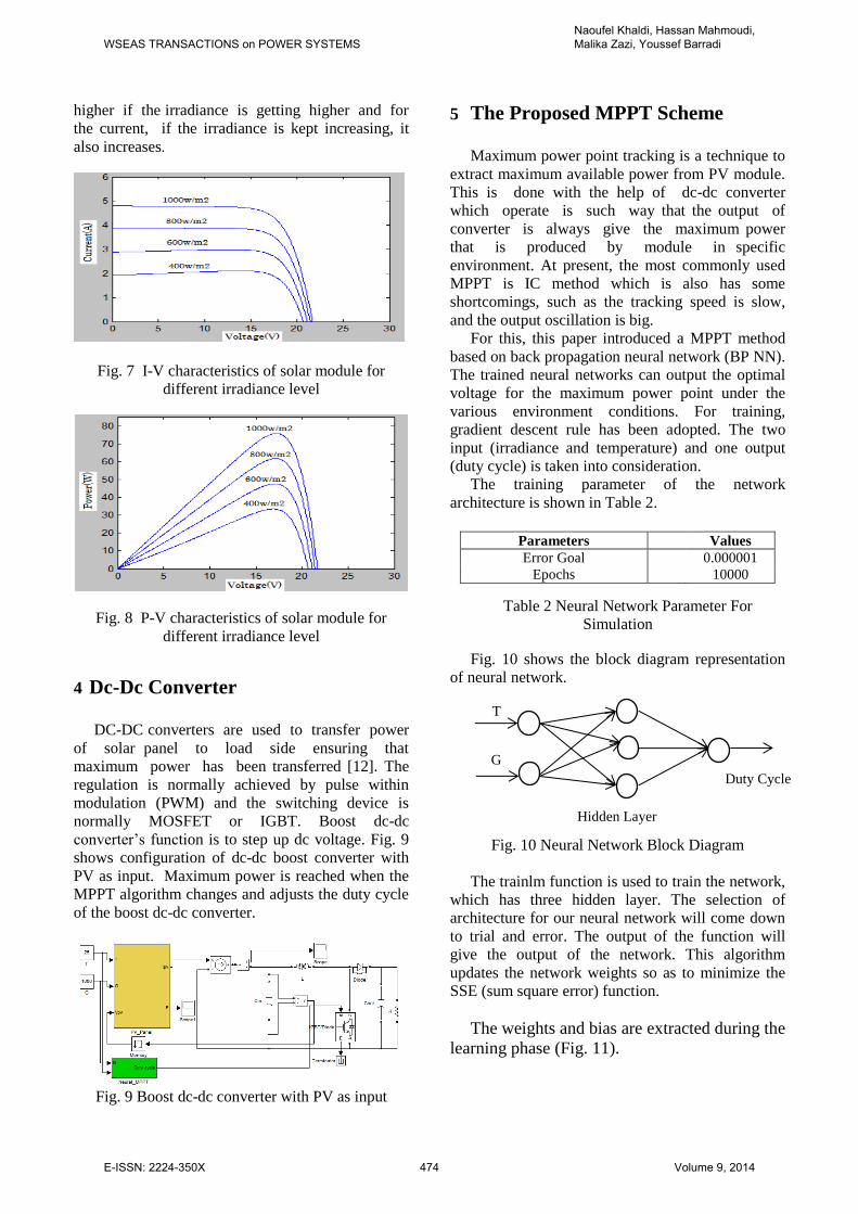
higher if the irradiance is getting higher and for
the current, if the irradiance is kept increasing, it
also increases.
Fig. 7 I-V characteristics of solar module for
different irradiance level
Fig. 8 P-V characteristics of solar module for
different irradiance level
4 Dc-Dc Converter
DC-DC converters are used to transfer power
of solar panel to load side ensuring that
maximum power has been transferred [12]. The
regulation is normally achieved by pulse within
modulation (PWM) and the switching device is
normally MOSFET or IGBT. Boost dc-dc
converter’s function is to step up dc voltage. Fig. 9
shows configuration of dc-dc boost converter with
PV as input. Maximum power is reached when the
MPPT algorithm changes and adjusts the duty cycle
of the boost dc-dc converter.
Fig. 9 Boost dc-dc converter with PV as input
5 The Proposed MPPT Scheme
Maximum power point tracking is a technique to
extract maximum available power from PV module.
This is done with the help of dc-dc converter
which operate is such way that the output of
converter is always give the maximum power
that is produced by module in specific
environment. At present, the most commonly used
MPPT is IC method which is also has some
shortcomings, such as the tracking speed is slow,
and the output oscillation is big.
For this, this paper introduced a MPPT method
based on back propagation neural network (BP NN).
The trained neural networks can output the optimal
voltage for the maximum power point under the
various environment conditions. For training,
gradient descent rule has been adopted. The two
input (irradiance and temperature) and one output
(duty cycle) is taken into consideration.
The training parameter of the network
architecture is shown in Table 2.
Parameters Values
Error Goal 0.000001
Epochs 10000
Table 2 Neural Network Parameter For
Simulation
Fig. 10 shows the block diagram representation
of neural network.
T
Fig. 10 Neural Network Block Diagram
The trainlm function is used to train the network,
which has three hidden layer. The selection of
architecture for our neural network will come down
to trial and error. The output of the function will
give the output of the network. This algorithm
updates the network weights so as to minimize the
SSE (sum square error) function.
The weights and bias are extracted during the
learning phase (Fig. 11).
G
Hidden Layer
Duty Cycle
WSEAS TRANSACTIONS on POWER SYSTEMSNaoufel Khaldi, Hassan Mahmoudi, Malika Zazi, Youssef Barradi
E-ISSN: 2224-350X 474 Volume 9, 2014
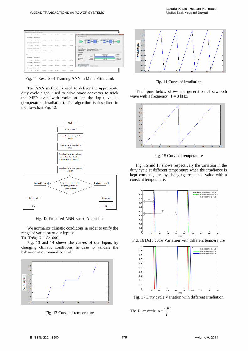
Fig. 11 Results of Training ANN in Matlab/Simulink
The ANN method is used to deliver the appropriate
duty cycle signal used to drive boost converter to track
the MPP even with variations of the input values
(temperature, irradiation). The algorithm is described in
the flowchart Fig. 12:
Fig. 12 Proposed ANN Based Algorithm
We normalize climatic conditions in order to unify the
range of variation of our inputs:
Tn=T/60; Gn=G/1000.
Fig. 13 and 14 shows the curves of our inputs by
changing climatic conditions, in case to validate the
behavior of our neural control.
Fig. 13 Curve of temperature
Fig. 14 Curve of irradiation
The figure below shows the generation of sawtooth
wave with a frequency f = 8 kHz.
Fig. 15 Curve of temperature
Fig. 16 and 17 shows respectively the variation in the
duty cycle at different temperature when the irradiance is
kept constant, and by changing irradiance value with a
constant temperature.
Fig. 16 Duty cycle Variation with different temperature
Fig. 17 Duty cycle Variation with different irradiation
The Duty cycle α =ton
T
0 10 20 30 40 50 60 70 80 900
0.1
0.2
0.3
0.4
0.5
0.6
0.7
0.8
0.9
1
time
IN1=0.1667,IN2= 0.2
IN1=0.4167,IN2= 0.2
IN1=0.9167,IN2= 0.2
0 10 20 30 40 50 60 70 80 900
0.1
0.2
0.3
0.4
0.5
0.6
0.7
0.8
0.9
1
time
IN1=0.1667,IN2= 0.2
IN1=0.1667,IN2= 0.4
IN1=0.1667,IN2= 0.8
ton
T
WSEAS TRANSACTIONS on POWER SYSTEMSNaoufel Khaldi, Hassan Mahmoudi, Malika Zazi, Youssef Barradi
E-ISSN: 2224-350X 475 Volume 9, 2014
6 Simulation Results
The results are obtained in MATLAB Simulink
environment. The proposed PV module was
connected to boost dc-dc converter to form a unit of
PV system. Simulation works were carried out with
conventional IC algorithm, and further with a neural
network MPPT control algorithms respectively for
evaluation and comparison analysis. The output of
dc-dc converter was 24V, The inductor value
was 82.5 mH, the input capacitor was 150 µF,
the output capacitor was 320 µF, and the load
was 10 ohm.
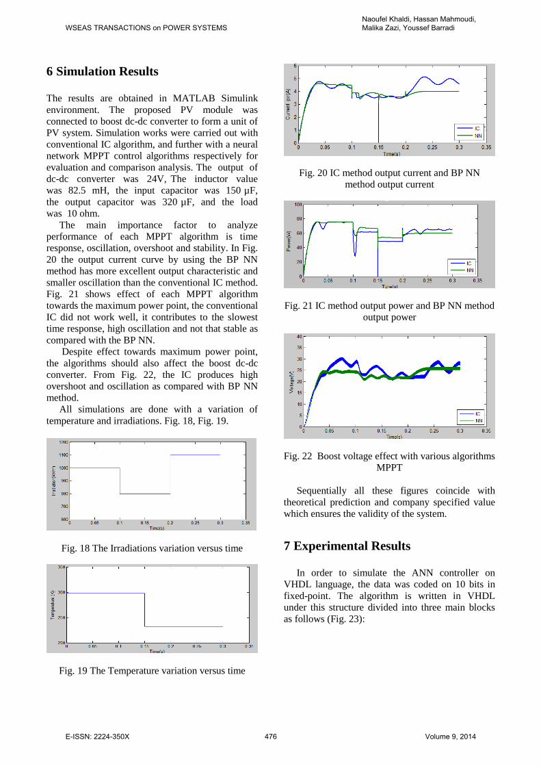
The main importance factor to analyze
performance of each MPPT algorithm is time
response, oscillation, overshoot and stability. In Fig.
20 the output current curve by using the BP NN
method has more excellent output characteristic and
smaller oscillation than the conventional IC method.
Fig. 21 shows effect of each MPPT algorithm
towards the maximum power point, the conventional
IC did not work well, it contributes to the slowest
time response, high oscillation and not that stable as
compared with the BP NN.
Despite effect towards maximum power point,
the algorithms should also affect the boost dc-dc
converter. From Fig. 22, the IC produces high
overshoot and oscillation as compared with BP NN
method.
All simulations are done with a variation of
temperature and irradiations. Fig. 18, Fig. 19.
Fig. 18 The Irradiations variation versus time
Fig. 19 The Temperature variation versus time
Fig. 20 IC method output current and BP NN
method output current
Fig. 21 IC method output power and BP NN method
output power
Fig. 22 Boost voltage effect with various algorithms
MPPT
Sequentially all these figures coincide with
theoretical prediction and company specified value
which ensures the validity of the system.
7 Experimental Results
In order to simulate the ANN controller on
VHDL language, the data was coded on 10 bits in
fixed-point. The algorithm is written in VHDL
under this structure divided into three main blocks
as follows (Fig. 23):
WSEAS TRANSACTIONS on POWER SYSTEMSNaoufel Khaldi, Hassan Mahmoudi, Malika Zazi, Youssef Barradi
E-ISSN: 2224-350X 476 Volume 9, 2014
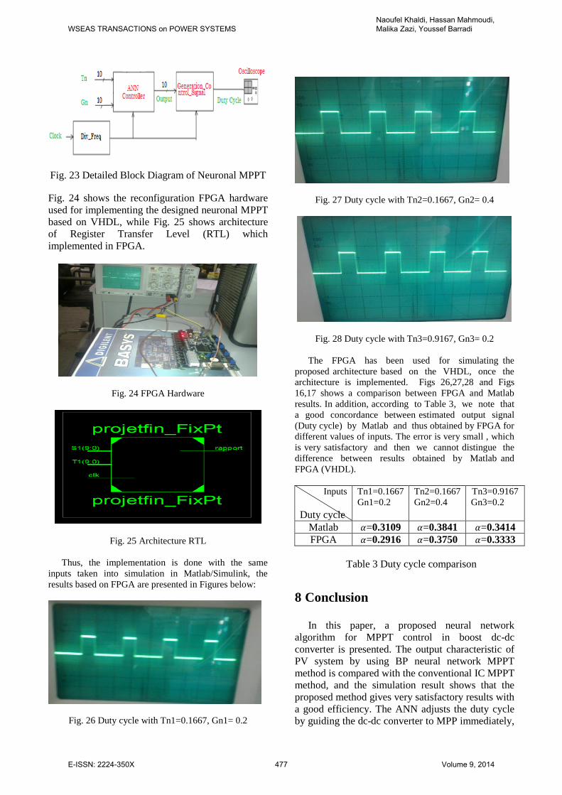
Fig. 23 Detailed Block Diagram of Neuronal MPPT
Fig. 24 shows the reconfiguration FPGA hardware
used for implementing the designed neuronal MPPT
based on VHDL, while Fig. 25 shows architecture
of Register Transfer Level (RTL) which
implemented in FPGA.
Fig. 24 FPGA Hardware
Fig. 25 Architecture RTL
Thus, the implementation is done with the same
inputs taken into simulation in Matlab/Simulink, the
results based on FPGA are presented in Figures below:
Fig. 26 Duty cycle with Tn1=0.1667, Gn1= 0.2
Fig. 27 Duty cycle with Tn2=0.1667, Gn2= 0.4
Fig. 28 Duty cycle with Tn3=0.9167, Gn3= 0.2
The FPGA has been used for simulating the
proposed architecture based on the VHDL, once the
architecture is implemented. Figs 26,27,28 and Figs
16,17 shows a comparison between FPGA and Matlab
results. In addition, according to Table 3, we note that
a good concordance between estimated output signal
(Duty cycle) by Matlab and thus obtained by FPGA for
different values of inputs. The error is very small , which
is very satisfactory and then we cannot distingue the
difference between results obtained by Matlab and
FPGA (VHDL).
Inputs
Duty cycle
Tn1=0.1667
Gn1=0.2
Tn2=0.1667
Gn2=0.4
Tn3=0.9167
Gn3=0.2
Matlab =0.3109 =0.3841 =0.3414
FPGA =0.2916 =0.3750 =0.3333
Table 3 Duty cycle comparison
8 Conclusion
In this paper, a proposed neural network
algorithm for MPPT control in boost dc-dc
converter is presented. The output characteristic of
PV system by using BP neural network MPPT
method is compared with the conventional IC MPPT
method, and the simulation result shows that the
proposed method gives very satisfactory results with
a good efficiency. The ANN adjusts the duty cycle
by guiding the dc-dc converter to MPP immediately,
WSEAS TRANSACTIONS on POWER SYSTEMSNaoufel Khaldi, Hassan Mahmoudi, Malika Zazi, Youssef Barradi
E-ISSN: 2224-350X 477 Volume 9, 2014
Whole algorithm is experimented well in kit FPGA
Spartan3E-100 TQ144 II pro of Xilinx.
References:
[1] Hasan Mahamudul, Monirul Islam, Ahmad
Shameem, Juel Rana and Dr. Henk Metselaar,
“Modelling of PV Module with Incremental
Conductance MPPT Controlled Buck-Boost
Converter”, 2nd International Conference on
Advances in Electrical Engineering, march
2013, pp. 197-202.
[2] AHMED M. OTHMAN, MAHDI M. El-
ARINI, AND AHMED FATHY, “Real world
Maximum Power Point Tracking Based on
Fuzzy Logic Control” WSEAS Trans. on Power
Systems, vol. 9, 2014, pp 232-241.
[3] Whei-Min Lin; Chih-Ming Hong; Chiung-
Hsing Chen, “Neural-Network-Based MPPT
Control of a Stand-Alone Hybrid Power
Generation System” IEEE Transactions on
Power Electronics, Volume: 26, 2011,
pp.3571 – 3581.
[4] N. Tat Luat and L Kay-Soon, "A global
maximum power point tracking scheme
employing DIRECT search algorithm for
photovoltaic systems" IEEE Trans. on Ind
Electron, Vol 57, No. 10, Jan 2010, pp.
3456-3467.
[5] S. Nema, R.K.Nema, and G.Agnihotri,
“Matlab/Simulink based study of
photovoltaic cells/modules/array and their
experimental verification” International
Journal of Energy and Environment, Volume
1, Issue 3, 2010,pp.487-500.
[6] Roberto Faranda, S.L., “Energy Comparison
of MPPT Techniques for PV Systems”.
WSEAS Trans. on Power Systems, vol. 3, No.6,
2008, pp 446-455.
[7] Jee-Hoon Jung, and S. Ahmed, “Model
Construction of Single Crystalline
Photovoltaic Panels for Real-time
Simulation” IEEE Energy Conversion
Congress & Expo, September 12-16, 2010,
Atlanta, USA.
[8] Marcelo Gradella Villala, Jonas Rafael
Gazoli,and Ernesto Ruppert Filho
“Comprehensive Approach to modeling and
simulation of photovoltaic arrays” IEEE
Transactions on power electronics, vol.24,
N0.5,May 2009.
[9] A. Ghaffari, S. Seshagiri, and M. Krsti' c,
"High-fidelity PV array modeling for
advanced MPPT design" in Proc. of IEEE
Canadian Conference on Electrical and
Computer Engineering (CCECE), 2012.
[10] Seyed Hossein Hosseinil, Amir Farakhor and
Saeideh Khadem Haghighian, “Novel
Algorithm of MPPT for PV Array Based on
Variable Step Newton-Raphson Method
Through Model Predictive Control” 13th
International Conference on Control,
Automation and Systems, Oct. 20-23, 2013, pp
1577-1582.
[11] A. Ushida and M. Tanaka, Electronic Circuit
Simulation. Japan: Corona ch. 5.1, 2002, pp.
148-158.
[12] Long Jie, Chen Ziran, “Research on the MPPT
Algorithms of Photovoltaic System Based on
PV Neural Network” Chinese Control and
Decision Conference, 2011, pp 1851-1854.
[13] Tamer T.N. Khatib, A. Mohamed And N. Amin
“An Efficient Maximum Power Point Tracking
Controller for Photovoltaic Systems Using New
Boost Converter Design and Improved Control
Algorithm”. WSEAS Trans. on Power Systems,
vol. 5, No.2, 2010, pp 53-63.
[14] Liu Liqun , Wang Zhixin, A variable voltage
MPPT control method for photovoltaic
generation system, WSEAS Transactions on
Circuits and Systems,vol.8, No.4, April 2009,
pp.335-349.
WSEAS TRANSACTIONS on POWER SYSTEMSNaoufel Khaldi, Hassan Mahmoudi, Malika Zazi, Youssef Barradi
E-ISSN: 2224-350X 478 Volume 9, 2014