Embed Size (px)
Citation preview

Application ReportSLAA577F–January 2013–Revised May 2014
Implementation of a Three-Phase Electronic Watt-HourMeter Using the MSP430F677x(A)
Mekre Mesganaw and Kripasagar Venkat ................................................................. Metering Applications
ABSTRACTThis application report describes the implementation of a three-phase electronic electricity meter using theTexas Instruments MSP430F677x(A) metering processor. This application report includes the necessaryinformation with regard to metrology software, hardware procedures for this single-chip implementation.
The source code and user interface that are described in this application report can be downloaded fromhttp://www.ti.com/lit/zip/slaa577. Other design documents for this EVM could be downloaded fromhttp://www.ti.com/tool/TIDM-THREEPHASEMETER-F6779.
WARNINGFailure to adhere to these steps and/or not heed the safetyrequirements at each step may lead to shock, injury, and damageto the hardware.
Contents1 Introduction ................................................................................................................... 22 System Diagrams ............................................................................................................ 33 Hardware Implementation .................................................................................................. 54 Software Implementation ................................................................................................... 75 Energy Meter Demo........................................................................................................ 186 Results and Calibration.................................................................................................... 277 Schematics.................................................................................................................. 37
List of Figures
1 Typical Per-Phase Connections Inside an Electronic Meter ........................................................... 32 3-Phase 4-Wire Star Connection Using MSP430F677x(A) ............................................................ 43 Simple Capacitive Power Supply for the MSP430 Energy Meter ..................................................... 54 Switching-Based Power Supply for the MSP430 Energy Meter ....................................................... 65 Analog Front End for Voltage Inputs ...................................................................................... 66 Analog Front End for Current Inputs ...................................................................................... 77 Foreground Process......................................................................................................... 88 Background Process ....................................................................................................... 129 Phase Compensation Using PRELOAD Register...................................................................... 1310 Frequency Measurement.................................................................................................. 1411 Pulse Generation for Energy Indication ................................................................................. 1512 Top View of the Three Phase Energy Meter EVM ..................................................................... 1813 Top View of the EVM With Components Highlighted.................................................................. 1914 Top View of the EVM With Test Setup Connections .................................................................. 21
1SLAA577F–January 2013–Revised May 2014 Implementation of a Three-Phase Electronic Watt-Hour Meter Using theMSP430F677x(A)Submit Documentation Feedback
Copyright © 2013–2014, Texas Instruments Incorporated
Introduction www.ti.com
15 Front View of the EVM With Test Setup Connections................................................................. 2116 Source Folder Structure ................................................................................................... 2517 Toolkit Compilation in IAR................................................................................................. 2518 Metrology Project Build in IAR............................................................................................ 2519 LCD Display................................................................................................................. 2820 ZigBee Radio ............................................................................................................... 2821 TI Designed IHD430 ....................................................................................................... 2922 GUI Config File Changed to Communicate With Meter ............................................................... 3023 GUI Startup Window ....................................................................................................... 3024 Results Window ............................................................................................................ 3125 Calibration Factors Window............................................................................................... 3226 Manual Calibration Window............................................................................................... 3227 Calibration Factors Window............................................................................................... 3428 Meter Features Window ................................................................................................... 3429 Energy Measurement Error Across Current With Customized CTs on EVM430-F6779.......................... 3530 Energy Measurement Error Across Current With High-End CTs .................................................... 3631 Schematics (1 of 4) ........................................................................................................ 3732 Schematics (2 of 4) ........................................................................................................ 3833 Schematics (3 of 4) ........................................................................................................ 3934 Schematics (4 of 4) ........................................................................................................ 40
List of Tables
1 Header Names and Jumper Settings on the F677x(A) EVM ......................................................... 222 Displayed Parameters ..................................................................................................... 273 Energy Measurement Error With Customized CTs on EVM430-F6779 (%)........................................ 354 Energy Measurement Error With High-End CTs (%) .................................................................. 36
1 IntroductionThe MSP430F677x(A) devices are the latest metering system-on-chip (SoC) that belongs to theMSP430F67xx family of devices. This family of devices belongs to the powerful 16-bit MSP430F6xxplatform, which brings in many new features and provides flexibility to support robust poly-phasemetrology solutions. These devices find their application in energy measurement and have the necessaryarchitecture to support them.
The F677x(A) has a powerful 25-MHz CPU with MSP430CPUX architecture. The analog front-endconsists of up to seven independent 24-bit ΣΔ analog to digital converters (ADC) based on a second-ordersigma-delta architecture that supports differential inputs. The sigma-delta ADCs (SD24_B) operateindependently and are capable of 24-bit results. They can be grouped together for simultaneous samplingof voltages and currents on the same trigger. In addition, it also has an integrated gain stage to supportgains up to 128 for amplification of low-output current sensors. A 32-bit x 32-bit hardware multiplier on thischip can be used to further accelerate math intensive operations during energy computation. The softwareenergy library supports calculation of various parameters for up to three-phase energy measurement. Thekey parameters calculated during energy measurements are: RMS current and voltage, active andreactive power and energies, power factor, and frequency. The library also provides the option to obtainraw samples of voltages and currents for advanced metering data such as harmonic analysis and totalharmonic distortion (THD). The application report has complete metrology source code provided as a zipfile (http://www.ti.com/lit/zip/slaa577).
MSP430 is a trademark of Texas Instruments.ZigBee is a trademark of ZigBee Alliance.All other trademarks are the property of their respective owners.
2 Implementation of a Three-Phase Electronic Watt-Hour Meter Using the SLAA577F–January 2013–Revised May 2014MSP430F677x(A) Submit Documentation Feedback
Copyright © 2013–2014, Texas Instruments Incorporated
www.ti.com System Diagrams
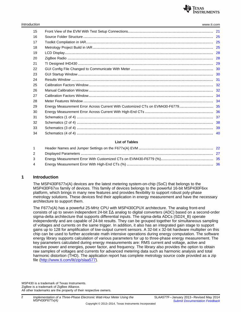
2 System DiagramsFigure 1 shows typical connections for one-phase electronic electricity (energy/e-) meters in real lifeapplications. For poly-phase meters, the connection in Figure 1 is duplicated for each phase. The acvoltages supported are 120 V/230 V at 50/60 Hz with the associated currents. The labels Line (L) andNeutral (N) are interchangeable and are indicative of ac mains voltage source from the energy utilities.
Figure 1. Typical Per-Phase Connections Inside an Electronic Meter
The following sections provide more information on the current and voltage sensors, ADCs, and otherfeatures.
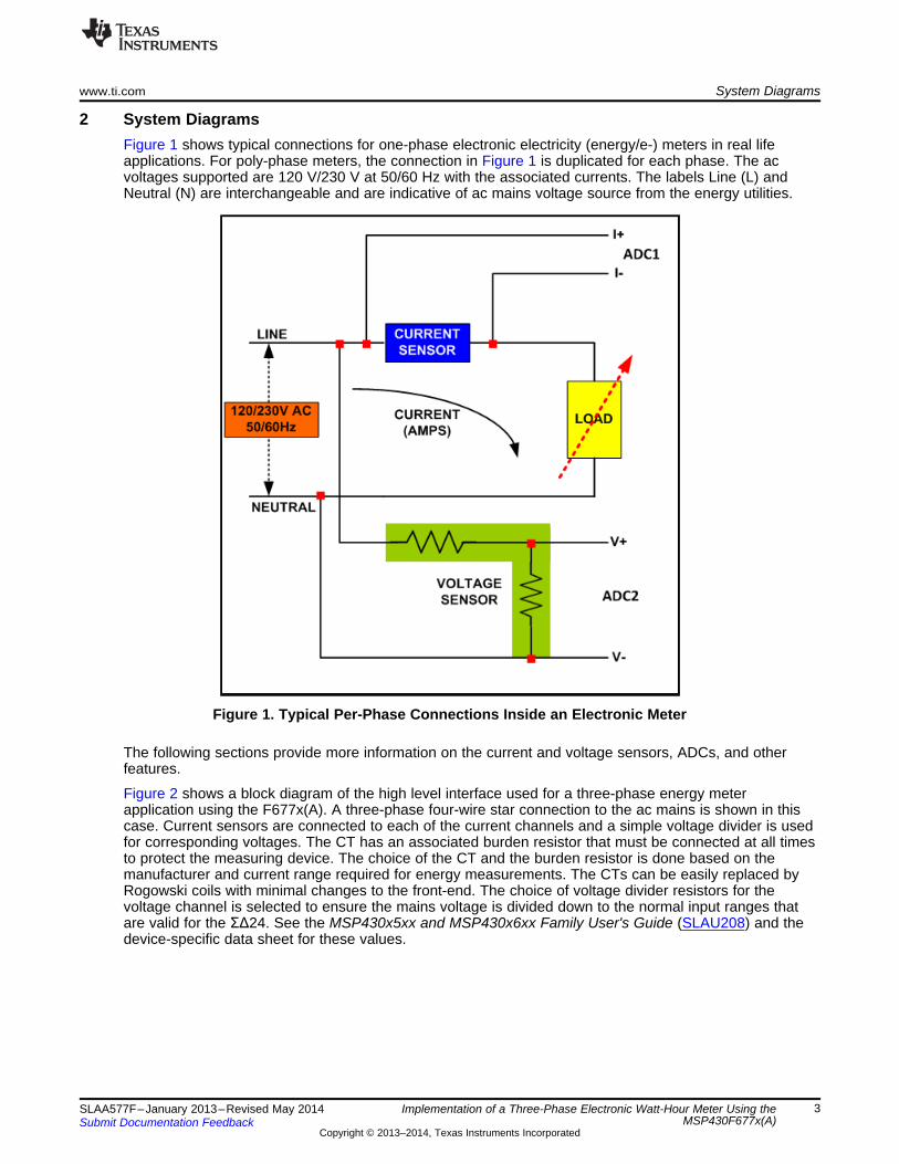
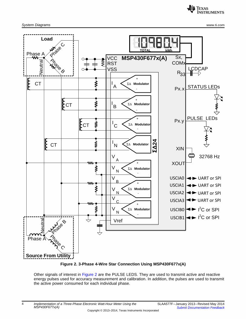
Figure 2 shows a block diagram of the high level interface used for a three-phase energy meterapplication using the F677x(A). A three-phase four-wire star connection to the ac mains is shown in thiscase. Current sensors are connected to each of the current channels and a simple voltage divider is usedfor corresponding voltages. The CT has an associated burden resistor that must be connected at all timesto protect the measuring device. The choice of the CT and the burden resistor is done based on themanufacturer and current range required for energy measurements. The CTs can be easily replaced byRogowski coils with minimal changes to the front-end. The choice of voltage divider resistors for thevoltage channel is selected to ensure the mains voltage is divided down to the normal input ranges thatare valid for the ΣΔ24. See the MSP430x5xx and MSP430x6xx Family User's Guide (SLAU208) and thedevice-specific data sheet for these values.
3SLAA577F–January 2013–Revised May 2014 Implementation of a Three-Phase Electronic Watt-Hour Meter Using theMSP430F677x(A)Submit Documentation Feedback
Copyright © 2013–2014, Texas Instruments Incorporated
6' Modulator
6' Modulator
-
Source From Utility
Load
CT
Phase A Phase
C
Phase B
Phase APha
se B
Phase C
Neu
tral
6' Modulator
6' Modulator
6' Modulator
+
+
-
+
-
+
-
+
-
+
-
Sx, COMxRST
VCC MSP430F677x(A)
R33VSS
32768 Hz
XIN
XOUT
Px.x
Px.y
STATUS LEDs
TOTAL
AB
kWh
6' Modulator
+
-
LCDCAP
+
-
6' Modulator
¯û
24
USCIA1
USCIA0
USCIA2
USCIB0
UART or SPI
I2C or SPI
USCIA3
USCIB1 I2C or SPI
UART or SPI
UART or SPI
UART or SPI
PULSE LEDs
Vref
IA
IB
IC
VA
VB
VN
VN
VC
VN
IN
Neu
tral
CT
CT
CT
System Diagrams www.ti.com
Figure 2. 3-Phase 4-Wire Star Connection Using MSP430F677x(A)
Other signals of interest in Figure 2 are the PULSE LEDS. They are used to transmit active and reactiveenergy pulses used for accuracy measurement and calibration. In addition, the pulses are used to transmitthe active power consumed for each individual phase.
4 Implementation of a Three-Phase Electronic Watt-Hour Meter Using the SLAA577F–January 2013–Revised May 2014MSP430F677x(A) Submit Documentation Feedback
Copyright © 2013–2014, Texas Instruments Incorporated

2.2uF10
0u
F/1
00
V
0.22uF/305VAC
0.22uF/305VAC
Vsupply
1N4007
1N4007
1N4757A
1N4757A
0
0.22uF/305VAC1N4007
1N4757A
TPS54060_DGQ_10
1M
33
.2K 1M
0.01uF
0.1
uF
100
100
100
22
.1k
.056uF 100pF
NEUTRAL
NEUTRAL
NEUTRAL
B1
60
1mH
47uF
NEUTRAL
51
.13
1.6
k1
0k
NEUTRAL
C48
C1
02
C46
C50
D20
D22D21
D19
R39
C39D18
D17
BOOT1
VIN2
EN3
SS/TR4
RT/CLK5 PWRGD 6VSENSE 7
COMP 8GND 9
PH 10
U3
R3
5R
37
R3
8
C45
C4
7
R92
R93
R94
R9
5
C60 C61
D2
3
L7
C62
R9
6R
97
R9
8
VCC_PL
DGND
NEUTRAL
P1+1
P2+1
P3+1
+
www.ti.com Hardware Implementation
3 Hardware ImplementationThis section describes the hardware for the design of a working 3-phase energy meter that uses theF677x(A).
3.1 Power SupplyThe MSP430™ family of devices comprises ultralow-power microcontrollers from Texas Instruments.These devices support a number of low-power modes and also have low-power consumption during activemode when the CPU and other peripherals are active. The low-power feature of this device family allowsdesign of the power supply to be simple and inexpensive. The power supply allows the operation of theenergy meter powered directly from the mains. The next sections describe the various power supplyoptions that are available to users to support their design.
3.1.1 Resistor Capacitor (RC) Power SupplyFigure 3 shows a capacitor power supply that provides a single output voltage of 3.3 V directly from themains of 120/230 V RMS ac at 50/60 Hz.
Figure 3. Simple Capacitive Power Supply for the MSP430 Energy Meter
Appropriate values of resistors (R92, R93, and R94) and capacitors (C39, C46, and C50) are chosenbased on the required output current drive of the power supply. Voltage from mains is directly fed to a RCbased circuit followed by a rectification circuit to provide a dc voltage for the operation of the MSP430.This dc voltage is regulated to 3.3 V for full-speed operation of the MSP430. The design equations for thepower supply are given in the application report Improved Load Current Capability for Cap-Drop Off-LinePower Supply for E-Meter (SLVA491). The above configuration allows all three phases to contribute to thecurrent drive, which is approximately three times the drive available from only one phase. If even higheroutput drive is required, the same circuitry can be used followed by an NPN output buffer. Another optionwould be to replace the above circuitry with a transformer-based or switching-based power supply.
3.1.2 Switching Power SupplyFigure 4 shows a switching-based power supply that provides a single output voltage of 3.3 V directly fromthe ac mains at 100 V to 230 V RMS. In the configuration shown, the meter is powered as long as there isac voltage on Phase C, corresponding to pad LINE 3 on the hardware and P3+1 on the schematic. Theinternal circuitry of a switching power supply is omitted from this application report. For the drive of thepower supply, refer to the documentation of the power supply module.
5SLAA577F–January 2013–Revised May 2014 Implementation of a Three-Phase Electronic Watt-Hour Meter Using theMSP430F677x(A)Submit Documentation Feedback
Copyright © 2013–2014, Texas Instruments Incorporated
47p
47p
15n
AGND
AGND
330k 330k 330k
2.3
7K
1k
1k
S20K
275
EXCML20A
EXCML20A
AGND
C3
C13
C12
R11 R12 R13
R19
R18
R34
R3
L5
L6
LINE3
N3
V3+
V3-
P3+1
NEUTRAL
LINE3
V3
150uF
0.1
uF
SMAJ5.0ABCT
4.7u/400V
LL
NN
NCNC
26 26
22 22
VO+ VO+
VO- VO-
C101
C42
ZD
3
C100
DGND
NEUTRAL
VCC_ISO
P3+1
+
Hardware Implementation www.ti.com
Figure 4. Switching-Based Power Supply for the MSP430 Energy Meter
3.2 Analog InputsThe MSP430 analog front end, which consists of the ΣΔ ADC, is differential and requires that the inputvoltages at the pins do not exceed ±930 mV (gain = 1). To meet this specification, the current and voltageinputs must be divided down. In addition, the ΣΔ24 allows a maximum negative voltage of -1 V. Therefore,ac signals from mains can be directly interfaced without the need for level shifters. This section describesthe analog front end used for voltage and current channels.
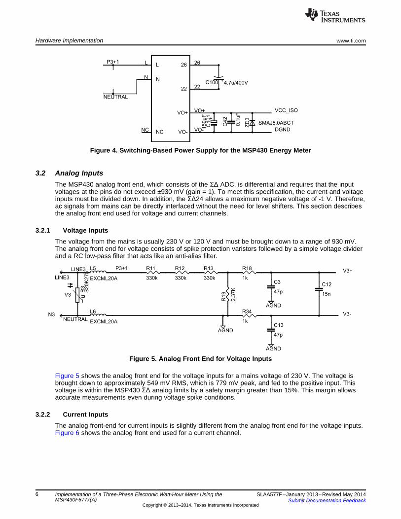
3.2.1 Voltage InputsThe voltage from the mains is usually 230 V or 120 V and must be brought down to a range of 930 mV.The analog front end for voltage consists of spike protection varistors followed by a simple voltage dividerand a RC low-pass filter that acts like an anti-alias filter.
Figure 5. Analog Front End for Voltage Inputs
Figure 5 shows the analog front end for the voltage inputs for a mains voltage of 230 V. The voltage isbrought down to approximately 549 mV RMS, which is 779 mV peak, and fed to the positive input. Thisvoltage is within the MSP430 ΣΔ analog limits by a safety margin greater than 15%. This margin allowsaccurate measurements even during voltage spike conditions.
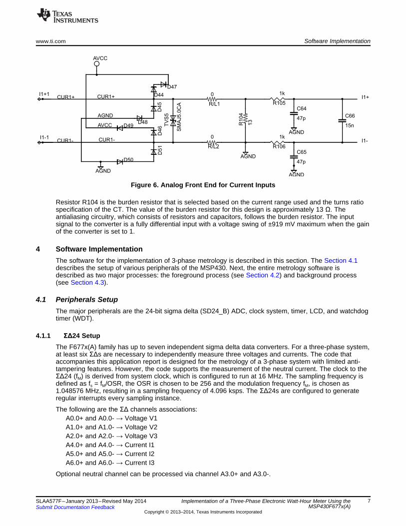
3.2.2 Current InputsThe analog front-end for current inputs is slightly different from the analog front end for the voltage inputs.Figure 6 shows the analog front end used for a current channel.
6 Implementation of a Three-Phase Electronic Watt-Hour Meter Using the SLAA577F–January 2013–Revised May 2014MSP430F677x(A) Submit Documentation Feedback
Copyright © 2013–2014, Texas Instruments Incorporated
0
47p
47p
15n
AGND0
AVCC
13
1k
1k
SM
AJ5.0
CA
AGND
AGNDAGND
R/L1C64
C65
C66
R/L2
R104
R105
R106
D44
D45
D46 T
VS
5
I1+1
I1-1
D47
D48D49
D50D
51
I1+
I1-
AGND
CUR1+CUR1+
CUR1-CUR1-
AVCC
www.ti.com Software Implementation
Figure 6. Analog Front End for Current Inputs
Resistor R104 is the burden resistor that is selected based on the current range used and the turns ratiospecification of the CT. The value of the burden resistor for this design is approximately 13 Ω. Theantialiasing circuitry, which consists of resistors and capacitors, follows the burden resistor. The inputsignal to the converter is a fully differential input with a voltage swing of ±919 mV maximum when the gainof the converter is set to 1.
4 Software ImplementationThe software for the implementation of 3-phase metrology is described in this section. The Section 4.1describes the setup of various peripherals of the MSP430. Next, the entire metrology software isdescribed as two major processes: the foreground process (see Section 4.2) and background process(see Section 4.3).
4.1 Peripherals SetupThe major peripherals are the 24-bit sigma delta (SD24_B) ADC, clock system, timer, LCD, and watchdogtimer (WDT).
4.1.1 ΣΔ24 SetupThe F677x(A) family has up to seven independent sigma delta data converters. For a three-phase system,at least six ΣΔs are necessary to independently measure three voltages and currents. The code thataccompanies this application report is designed for the metrology of a 3-phase system with limited anti-tampering features. However, the code supports the measurement of the neutral current. The clock to theΣΔ24 (fM) is derived from system clock, which is configured to run at 16 MHz. The sampling frequency isdefined as fs = fM/OSR, the OSR is chosen to be 256 and the modulation frequency fM, is chosen as1.048576 MHz, resulting in a sampling frequency of 4.096 ksps. The ΣΔ24s are configured to generateregular interrupts every sampling instance.
The following are the ΣΔ channels associations:A0.0+ and A0.0- → Voltage V1A1.0+ and A1.0- → Voltage V2A2.0+ and A2.0- → Voltage V3A4.0+ and A4.0- → Current I1A5.0+ and A5.0- → Current I2A6.0+ and A6.0- → Current I3
Optional neutral channel can be processed via channel A3.0+ and A3.0-.
7SLAA577F–January 2013–Revised May 2014 Implementation of a Three-Phase Electronic Watt-Hour Meter Using theMSP430F677x(A)Submit Documentation Feedback
Copyright © 2013–2014, Texas Instruments Incorporated
RESET
HW setup:
Clock, SD24_B, Port pins,RTC_C, eUSCI, LCD
Calculate RMS Current, RMS
Voltage, Active Power, Apparent
Power, Reactive Power,Frequency(Hz), and Power
Factor
1 second of Energy
accumulated? Wait for
acknowledgement from
Background process
Y
N
LCD Display Management
Send Cumulative Three-Phase
Total Active Power to ZigBeeTransmitter (OPTIONAL)
Software Implementation www.ti.com
4.1.2 Real-Time Clock (RTC_C)The RTC_C is a real-time clock module that is configured to give precise 1 second interrupts. Based onthese 1‑second interrupts, the time and date are updated in software, as necessary.
4.1.3 LCD ControllerThe LCD controller on the MSP430F677x(A) can support up to 8-mux displays and 320 segments. It isalso equipped with an internal charge pump that can be used for good contrast. In the current design, theLCD controller is configured to work in 4-mux mode using 160 segments with a refresh rate set toACLK/64, which is 512 Hz. For information, about the parameters that are displayed on the LCD, seeSection 6.1.
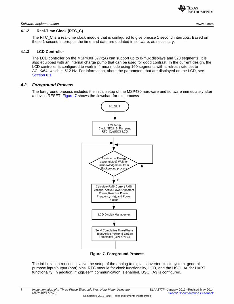
4.2 Foreground ProcessThe foreground process includes the initial setup of the MSP430 hardware and software immediately aftera device RESET. Figure 7 shows the flowchart for this process
Figure 7. Foreground Process
The initialization routines involve the setup of the analog to digital converter, clock system, generalpurpose input/output (port) pins, RTC module for clock functionality, LCD, and the USCI_A0 for UARTfunctionality. In addition, if ZigBee™ communication is enabled, USCI_A3 is configured.
8 Implementation of a Three-Phase Electronic Watt-Hour Meter Using the SLAA577F–January 2013–Revised May 2014MSP430F677x(A) Submit Documentation Feedback
Copyright © 2013–2014, Texas Instruments Incorporated
1, ,
( )* ( )
*
Samplecount
ph phn
RMS ph i ph
i n i n
I KSample count
==
å
1, ,
( )* ( )
*
Samplecount
ph phn
RMS ph v ph
v n v n
V KSample count
==
å
www.ti.com Software Implementation
After the hardware is setup, the foreground process waits for the background process to notify it tocalculate new metering parameters. This notification is done through a status flag every time a frame ofdata is available for processing. The data frame consists of processed current, voltage, active energy, andreactive energy accumulated for one second. This is equivalent to accumulation of 50 or 60 cycles of datasynchronized to the incoming voltage signal. In addition, a sample counter keeps track of how manysamples have been accumulated over this frame period. This count can vary as the software synchronizeswith the incoming mains frequency.
The set of data samples consists of processed current, voltage, active energy, and reactive energy.Processed voltages are accumulated in 48-bit registers. In contrast, processed currents, active energies,and reactive energies are accumulated in separate 64-bit registers to further process and obtain the RMSand mean values. Using the foreground's calculated values of active and reactive power, the apparentpower is calculated. The frequency (in Hertz) and power factor are also calculated using parameterscalculated by the background process using the formulas in Section 4.2.1.
4.2.1 Computation FormulasThis section briefly describes the formulas used for the voltage, current, and energy calculations.
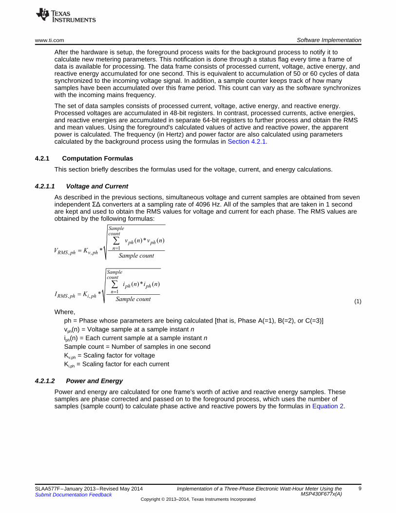
4.2.1.1 Voltage and CurrentAs described in the previous sections, simultaneous voltage and current samples are obtained from sevenindependent ΣΔ converters at a sampling rate of 4096 Hz. All of the samples that are taken in 1 secondare kept and used to obtain the RMS values for voltage and current for each phase. The RMS values areobtained by the following formulas:
(1)
Where,ph = Phase whose parameters are being calculated [that is, Phase A(=1), B(=2), or C(=3)]vph(n) = Voltage sample at a sample instant niph(n) = Each current sample at a sample instant nSample count = Number of samples in one secondKv,ph = Scaling factor for voltageKi,ph = Scaling factor for each current
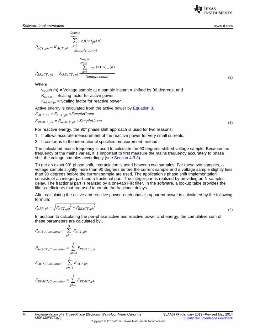
4.2.1.2 Power and EnergyPower and energy are calculated for one frame's worth of active and reactive energy samples. Thesesamples are phase corrected and passed on to the foreground process, which uses the number ofsamples (sample count) to calculate phase active and reactive powers by the formulas in Equation 2.
9SLAA577F–January 2013–Revised May 2014 Implementation of a Three-Phase Electronic Watt-Hour Meter Using theMSP430F677x(A)Submit Documentation Feedback
Copyright © 2013–2014, Texas Instruments Incorporated
3
REACT,Cumulative REACT,phph-1
E = Eå
3
ACT,Cumulative ACT,phph=1
E = Eå
3
, ,
1
REACT Cumulative REACT phph
P P
=
= å
3
, ,
1
ACT Cumulative ACT phph
P P
=
= å
2 2, , ,APP ph ACT ph REACT phP P P= +
, ,
, ,
ACT ph ACT ph
REACT ph REACT ph
E P SampleCount
E P SampleCount
= ´
= ´
901
, ,
( ) ( )
Samplecount
phn
REACT ph REACT ph
v n i n
P KSample count
=
´
=
å
1, ,
( ) ( )
Samplecount
phn
ACT ph ACT ph
v n i n
P KSample count
=
´
=
å
Software Implementation www.ti.com
(2)
Where,v90,ph (n) = Voltage sample at a sample instant n shifted by 90 degrees, andKACT,ph = Scaling factor for active powerKREACT,ph = Scaling factor for reactive power
Active energy is calculated from the active power by Equation 3.
(3)
For reactive energy, the 90° phase shift approach is used for two reasons:1. It allows accurate measurement of the reactive power for very small currents.2. It conforms to the international specified measurement method.
The calculated mains frequency is used to calculate the 90 degrees-shifted voltage sample. Because thefrequency of the mains varies, it is important to first measure the mains frequency accurately to phaseshift the voltage samples accordingly (see Section 4.3.3).
To get an exact 90° phase shift, interpolation is used between two samples. For these two samples, avoltage sample slightly more than 90 degrees before the current sample and a voltage sample slightly lessthan 90 degrees before the current sample are used. The application's phase shift implementationconsists of an integer part and a fractional part. The integer part is realized by providing an N samplesdelay. The fractional part is realized by a one-tap FIR filter. In the software, a lookup table provides thefilter coefficients that are used to create the fractional delays.
After calculating the active and reactive power, each phase's apparent power is calculated by the followingformula:
(4)
In addition to calculating the per-phase active and reactive power and energy, the cumulative sum ofthese parameters are calculated by .
10 Implementation of a Three-Phase Electronic Watt-Hour Meter Using the SLAA577F–January 2013–Revised May 2014MSP430F677x(A) Submit Documentation Feedback
Copyright © 2013–2014, Texas Instruments Incorporated
Act
Apparent
Act
Apparent
P,if capacitive load
PInternal Representation of Power Factor =
P- ,if inducitive load
P
ìïïíïïî
Sampling Rate (samples / second)Frequency (Hz)=
Frequency (samples / cycle)
www.ti.com Software Implementation
4.2.1.3 Frequency (Hz)The background process calculates the frequency in terms of samples per mains cycle. The foregroundprocess then converts this to Hertz by Equation 5.
(5)
4.2.1.4 Power FactorAfter the active power and apparent power have been calculated, the absolute value of the power factor iscalculated. In the meter's internal representation of power factor, a positive power factor corresponds to acapacitive load and a negative power factor corresponds to an inductive load. The sign of the internalrepresentation of power factor is determined by whether the current leads or lags voltage, which isdetermined in the background process. Therefore, the internal representation of power factor is calculatedby the following formula:
(6)
4.3 Background ProcessThe background process uses the ΣΔ interrupt as a trigger to collect voltage and current samples (sevenvalues in total). These samples are used to calculate intermediate results. Because 16-bit voltage samplesare used, the voltage samples are further processed and accumulated in dedicated 48-bit registers. Incontrast, since 24-bit current samples are used, the current samples are processed and accumulated indedicated 64-bit registers. Per-phase active power and reactive power are also accumulated in 64-bitregisters.
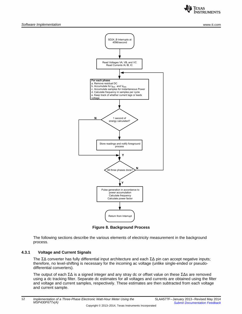
The background function deals mainly with timing critical events in software. After sufficient samples(approximately one second's worth) have been accumulated, then the foreground function is triggered tocalculate the final values of VRMS, IRMS, active, reactive, and apparent powers, active, reactive, andapparent energy, frequency, and power factor. The background process is also wholly responsible for thecalculation of energy proportional pulses, frequency (in samples/cycle), and determining current lead andlag conditions. Figure 8 shows the flow diagram of the background process.
11SLAA577F–January 2013–Revised May 2014 Implementation of a Three-Phase Electronic Watt-Hour Meter Using theMSP430F677x(A)Submit Documentation Feedback
Copyright © 2013–2014, Texas Instruments Incorporated
SD24_B Interrupts at4096/second
Read Voltages VA, VB, and VCRead Currents IA, IB, IC
For each phase:
a. Remove residual DCb. Accumulate for IRMS and VRMS
c. Accumulate samples for instantaneous Power
d. Calculate frequency in samples per cycle
e. Keep track of whether current lags or leads
voltage
Store readings and notify foregroundprocess
Pulse generation in accordance topower accumulation
Calculate frequency
Calculate power factor
Return from Interrupt
1 second ofenergy calculated?
N
Y
All three phases done?
Y
N
Software Implementation www.ti.com
Figure 8. Background Process
The following sections describe the various elements of electricity measurement in the backgroundprocess.
4.3.1 Voltage and Current SignalsThe ΣΔ converter has fully differential input architecture and each ΣΔ pin can accept negative inputs;therefore, no level-shifting is necessary for the incoming ac voltage (unlike single-ended or pseudo-differential converters).
The output of each ΣΔ is a signed integer and any stray dc or offset value on these ΣΔs are removedusing a dc tracking filter. Separate dc estimates for all voltages and currents are obtained using the filterand voltage and current samples, respectively. These estimates are then subtracted from each voltageand current sample.
12 Implementation of a Three-Phase Electronic Watt-Hour Meter Using the SLAA577F–January 2013–Revised May 2014MSP430F677x(A) Submit Documentation Feedback
Copyright © 2013–2014, Texas Instruments Incorporated
o oIN IN
DegS M
360 × f 360 × fDelay resolution = =
OSR× f f
www.ti.com Software Implementation
The resulting instantaneous voltage and current samples are used to generate the following intermediateresults:• Accumulated squared values of voltages and currents, which is used for VRMS and IRMS calculations,
respectively.• Accumulated energy samples to calculate active energies.• Accumulated energy samples using current and 90° phase shifted voltage to calculate reactive
energies.
These accumulated values are processed by the foreground process.
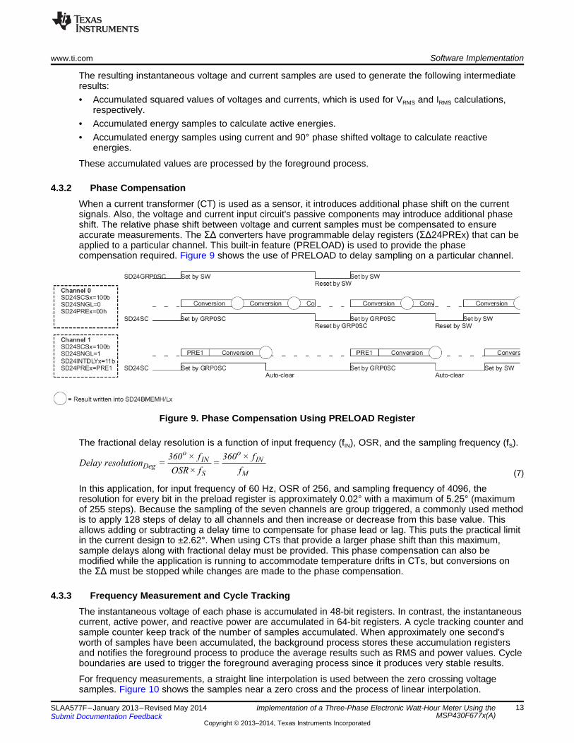
4.3.2 Phase CompensationWhen a current transformer (CT) is used as a sensor, it introduces additional phase shift on the currentsignals. Also, the voltage and current input circuit's passive components may introduce additional phaseshift. The relative phase shift between voltage and current samples must be compensated to ensureaccurate measurements. The ΣΔ converters have programmable delay registers (ΣΔ24PREx) that can beapplied to a particular channel. This built-in feature (PRELOAD) is used to provide the phasecompensation required. Figure 9 shows the use of PRELOAD to delay sampling on a particular channel.
Figure 9. Phase Compensation Using PRELOAD Register
The fractional delay resolution is a function of input frequency (fIN), OSR, and the sampling frequency (fS).
(7)
In this application, for input frequency of 60 Hz, OSR of 256, and sampling frequency of 4096, theresolution for every bit in the preload register is approximately 0.02° with a maximum of 5.25° (maximumof 255 steps). Because the sampling of the seven channels are group triggered, a commonly used methodis to apply 128 steps of delay to all channels and then increase or decrease from this base value. Thisallows adding or subtracting a delay time to compensate for phase lead or lag. This puts the practical limitin the current design to ±2.62°. When using CTs that provide a larger phase shift than this maximum,sample delays along with fractional delay must be provided. This phase compensation can also bemodified while the application is running to accommodate temperature drifts in CTs, but conversions onthe ΣΔ must be stopped while changes are made to the phase compensation.
4.3.3 Frequency Measurement and Cycle TrackingThe instantaneous voltage of each phase is accumulated in 48-bit registers. In contrast, the instantaneouscurrent, active power, and reactive power are accumulated in 64-bit registers. A cycle tracking counter andsample counter keep track of the number of samples accumulated. When approximately one second'sworth of samples have been accumulated, the background process stores these accumulation registersand notifies the foreground process to produce the average results such as RMS and power values. Cycleboundaries are used to trigger the foreground averaging process since it produces very stable results.
For frequency measurements, a straight line interpolation is used between the zero crossing voltagesamples. Figure 10 shows the samples near a zero cross and the process of linear interpolation.
13SLAA577F–January 2013–Revised May 2014 Implementation of a Three-Phase Electronic Watt-Hour Meter Using theMSP430F677x(A)Submit Documentation Feedback
Copyright © 2013–2014, Texas Instruments Incorporated

noise corrupted samples
good samples
linear interpolation
Software Implementation www.ti.com
Figure 10. Frequency Measurement
Because noise spikes can also cause errors, the application uses a rate of change check to filter out thepossible erroneous signals and make sure that the two points are interpolated from are genuine zerocrossing points. For example, with two negative samples, a noise spike can make one of them positive,and therefore, make the negative and positive pair looks as if there is a zero crossing.
The resultant cycle-to-cycle timing goes through a weak low-pass filter to further smooth out cycle-to-cyclevariations. This results in a stable and accurate frequency measurement that is tolerant of noise.
4.3.4 LED Pulse GenerationIn electricity meters, the energy consumed is normally measured in fraction of kilowatt-hour (kWh) pulses.This information can be used to calibrate any meter for accurate measurement. Typically, the measuringelement (the MSP430 microcontroller) is responsible to generate pulses proportional to the energyconsumed. To serve both these tasks efficiently, pulse generation must be accurate with relatively littlejitter. Although, time jitters are not an indication of bad accuracy, they give a negative indication on theoverall accuracy of the meter. Hence the jitter must be averaged out.
This application uses average power to generate these energy pulses. The average power (calculated bythe foreground process) is accumulated every ΣΔ interrupt, thereby spreading the accumulated energyfrom the previous 1 second time frame evenly for each interrupt in the current 1 second time frame. This isequivalent to converting it to energy. When the accumulated energy crosses a threshold, a pulse isgenerated. The amount of energy above this threshold is kept and new energy value is added on top of itin the next interrupt cycle. Because the average power tends to be a stable value, this way of generatingenergy pulses are very steady and free of jitter.
The threshold determines the energy "tick" specified by meter manufacturers and is a constant. It isusually defined in pulses per kWh or just in kWh. One pulse is generated for every energy "tick". Forexample, in this application, the number of pulses generated per kWh is set to 6400 for active and reactiveenergies. The energy "tick" in this case is 1 kWh/6400. Energy pulses are generated and available on aheader and also via LEDs on the board. General-purpose I/O (port) pins are used to produce the pulses.
In the EVM, the LEDs that are labeled LED1, LED2, LED3, and LED_ACT correspond to the active energyconsumption for phase A, phase B, phase C, and the cumulative three-phase sum, respectively.LED_REACT corresponds to the cumulative three-phase reactive energy sum. The number of pulses perkWh and each pulse duration can be configured in software. Figure 11 shows the flow diagram for pulsegeneration.
14 Implementation of a Three-Phase Electronic Watt-Hour Meter Using the SLAA577F–January 2013–Revised May 2014MSP430F677x(A) Submit Documentation Feedback
Copyright © 2013–2014, Texas Instruments Incorporated

SD interrupts at
4096 Hz
EnergyAccumulator+=
Average Power
Energy Accumulator >1 tick?
Energy Accumulator =Energy Accumulator –
1 tick
Generate 1pulse
Proceed to othertasks
Y
N
www.ti.com Software Implementation
Figure 11. Pulse Generation for Energy Indication
The average power is in units of 0.01 W and the 1 kWh threshold is defined as:
1 kWh threshold = (1 / 0.01) × 1 kW × (number of interrupts per second) × (number of seconds in onehour)
= 100000 × 4096 × 3600 = 0x15752A00000
4.4 Energy Meter ConfigurationInclude files are used to initialize and configure the energy meter to perform several metrology functions.This section describes the user-configurable options. The file that needs modification is emeter-3ph-neutral-6779(A).h, which is in the parent directory emeter-ng. This file includes macro definitions that areused during the normal operation of the meter.1. IHD430_SUPPORT: This macro allows ZigBee communication to an IHD430 in-home display. A
CC2530 transmitter must be placed in the EVM's RF connector to enable this. For more information,see Section 6.2.
2. SERIAL_CALIBRATION_SUPPORT: This macro allows the meter to be calibrated using the GUIprovided and RS-232 interface to the PC.
3. MAINS_FREQUENCY_SUPPORT: The macro configures the meter to measure the frequency of theac mains.
4. MAINS_NOMINAL_FREQUENCY: The macro defines the default ac mains frequency5. TOTAL_ENERGY_PULSES_PER_KW_HOUR: This macro defines the total number of pulses per
1 kWh of cumulative three-phase energy. In this application it is defined to 6400. It is important to notethat this value is not a standard. There could be a practical limit set on this number due to thereference meter's ability to accept fast pulses (due to large currents). This number is true for total threephase energy only.
6. PHASE_ENERGY_PULSES_PER_KW_HOUR: This macro defined the total number of pulses per1 kWh of energy at each phase. In this application it is defined to 6400 if pulses generation for each
15SLAA577F–January 2013–Revised May 2014 Implementation of a Three-Phase Electronic Watt-Hour Meter Using theMSP430F677x(A)Submit Documentation Feedback
Copyright © 2013–2014, Texas Instruments Incorporated

Software Implementation www.ti.com
individual phase has been enabled.7. INHIBIT_NEGATIVE_PHASE_POWER_ACCUMULATION: This macro prevents negative energy from
being accumulated at individual phases. Negative energy could be a result of reversed connection atthe voltage or current but not both at any of the phases.
8. INHIBIT_NEGATIVE_TOTAL_POWER_ACCUMULATION: This macro prevents negative energy frombeing accumulated for the three phases combined. Negative energy could be a result of reversedconnection at the voltage or current but not both at any of the phases.
9. ENERGY_PULSE_DURATION: This macro defines the duration of the LED ON time for an energypulse. This is measured in ADC samples (that is, increments of 1/4096 s). The maximum allowed is255, giving a pulse of approximately 62.5 ms, while 163 gives a 40-ms pulse. This duration might betoo large with adjacent pulses overlapping when very high currents are measured. It is recommendedthat this value be changed to a smaller number such as 20 if overlap is seen at the pulse outputs.
10. RESIDUAL_POWER_CUTOFF: Very low power levels should not be recorded at all, as they mightjust be rounding errors, noise, or the consumption of the meter itself. This value is the cutoff level, in0.01-W increments. In this application, it is set to 250, resulting in a start-energy of approximately2.5 W.
11. NEUTRAL_MONITOR_SUPPORT: This macro enables support for neutral monitoring. The seventhSD24_B is used for this purpose.
12. VRMS_SUPPORT: This macro is used to configure the meter to calculate VRMS from the voltagesamples.
13. IRMS_SUPPORT: This macro is used to configure the meter to calculate IRMS from the currentsamples.
14. REACTIVE_POWER_SUPPORT: This macro is used to configure the meter to calculate the reactivepower from the voltage and current samples.
15. REACTIVE_POWER_BY_QUADRATURE_SUPPORT: This macro is used to configure the meter tocalculate the reactive power from the delayed voltage samples by 90 degrees and current samplesinstead of using the power triangle method.
16. APPARENT_POWER_SUPPORT: This macro is used to configure the meter to calculate the apparentpower.
17. POWER_FACTOR_SUPPORT: This macro is used to configure the meter to calculate the powerfactor for both lead and lag. A frequency independent method, based on the ratio of scalar dotproducts, is used.
18. TOTAL_ACTIVE_ENERGY_SUPPORT: This macro is used to configure the meter to calculate thetotal 3-phase active energy consumption.
19. PER_PHASE_ACTIVE_ENERGY_SUPPORT: This macro is used to configure the meter to calculatethe active energy consumption for individual phases in addition to the total 3-phase active energy.
20. TOTAL_REACTIVE_ENERGY_SUPPORT: This macro is used to configure the meter to calculate thetotal 3-phase reactive energy consumption.
21. PER_PHASE_REACTIVE_ENERGY_SUPPORT: This macro is used to configure the meter tocalculate the reactive energy consumption for individual phases in addition to the total 3-phase reactiveenergy.
22. RTC_SUPPORT: This macro is used to configure the meter to support a real-time clock. A softwareRTC is implemented for this purpose.
23. CURRENT_PHASE_GAIN: This macro defines the gain of the SD24_B's internal programmable gainamplifier (PGA) for all the three currents. In this application it is set to 1.
24. CURRENT_NEUTRAL_GAIN: This macro defines the gain of the SD24_B's internal PGA for neutralcurrent monitoring. In this application it is set to 16.
25. VOLTAGE_GAIN: This macro defines the gain of the SD24_B's internal programmable gain amplifier(PGA) for all the three voltages. In this application it is set to 1.
26. PHASE_REVERSED_DETECTION_SUPPORT: This macro configures the meter to detect reversedpower condition.
27. PHASE_REVERSED_IS_TAMPERING: This macro configures the meter to treat phase reversedconnections as tampering.
16 Implementation of a Three-Phase Electronic Watt-Hour Meter Using the SLAA577F–January 2013–Revised May 2014MSP430F677x(A) Submit Documentation Feedback
Copyright © 2013–2014, Texas Instruments Incorporated

www.ti.com Software Implementation
28. DEFAULT_V_RMS_SCALE_FACTOR_A: This macro holds the scaling factor for voltage at phase A.Set this factor to an approximately correct value, and it will be fine tuned during calibration.
29. DEFAULT_V_RMS_SCALE_FACTOR_B: This macro holds the scaling factor for voltage at phase B.Set this factor to an approximately correct value, and it will be fine tuned during calibration.
30. DEFAULT_V_RMS_SCALE_FACTOR_C: This macro holds the scaling factor for voltage at phase C.Set this factor to an approximately correct value, and it will be fine tuned during calibration.
31. DEFAULT_I_RMS_SCALE_FACTOR_A: This macro holds the scaling factor for current at phase A.Set this factor to an approximately correct value, and it will be fine tuned during calibration.
32. DEFAULT_I_RMS_SCALE_FACTOR_B: This macro holds the scaling factor for current at phase B.Set this factor to an approximately correct value, and it will be fine tuned during calibration.
33. DEFAULT_I_RMS_SCALE_FACTOR_C: This macro holds the scaling factor for current at phase C.Set this factor to an approximately correct value, and it will be fine tuned during calibration.
34. DEFAULT_P_SCALE_FACTOR_A_LOW: This macro holds the scaling factor for active power atphase A. Set this factor to an approximately correct value, and it will be fine tuned during calibration.
35. DEFAULT_P_SCALE_FACTOR_B_LOW: This macro holds the scaling factor for active power atphase B. Set this factor to an approximately correct value, and it will be fine tuned during calibration.
36. DEFAULT_P_SCALE_FACTOR_C_LOW: This macro holds the scaling factor for active power atphase C. Set this factor to an approximately correct value, and it will be fine tuned during calibration.
37. DEFAULT_I_RMS_SCALE_FACTOR_NEUTRAL: This macro holds the scaling factor for current atneutral. Set this factor to an approximately correct value, and it will be fine tuned during calibration.
38. DEFAULT_P_SCALE_FACTOR_NEUTRAL: This macro holds the scaling factor for active power atneutral. Set this factor to an approximately correct value, and it will be fine tuned during calibration.
39. DEFAULT_BASE_PHASE_A_CORRECTION_LOW: This macro holds the value for phase correctionto compensate for the delay coming from the current transformer at phase A. This can be set to avalue that is in fairly acceptable range, and it will be fine tuned under phase correction duringcalibration.
40. DEFAULT_BASE_PHASE_B_CORRECTION_LOW: This macro holds the value for phase correctionto compensate for the delay coming from the current transformer at phase B. This can be set to avalue that is in fairly acceptable range, and it will be fine tuned under phase correction duringcalibration.
41. DEFAULT_BASE_PHASE_C_CORRECTION_LOW: This macro holds the value for phase correctionto compensate for the delay coming from the current transformer at phase C. This can be set to avalue that is in fairly acceptable range, and it will be fine tuned under phase correction duringcalibration.
42. DEFAULT_NEUTRAL_BASE_PHASE_CORRECTION: This macro holds the value for phasecorrection to compensate for the delay at phase C. This can be set to a value that is in fairlyacceptable range, and it will be fine tuned under phase correction during calibration.
17SLAA577F–January 2013–Revised May 2014 Implementation of a Three-Phase Electronic Watt-Hour Meter Using theMSP430F677x(A)Submit Documentation Feedback
Copyright © 2013–2014, Texas Instruments Incorporated
Energy Meter Demo www.ti.com
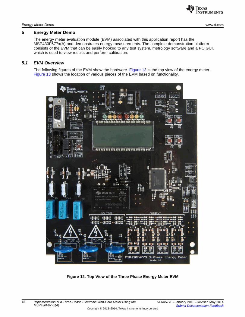
5 Energy Meter DemoThe energy meter evaluation module (EVM) associated with this application report has theMSP430F677x(A) and demonstrates energy measurements. The complete demonstration platformconsists of the EVM that can be easily hooked to any test system, metrology software and a PC GUI,which is used to view results and perform calibration.
5.1 EVM OverviewThe following figures of the EVM show the hardware. Figure 12 is the top view of the energy meter.Figure 13 shows the location of various pieces of the EVM based on functionality.
Figure 12. Top View of the Three Phase Energy Meter EVM
18 Implementation of a Three-Phase Electronic Watt-Hour Meter Using the SLAA577F–January 2013–Revised May 2014MSP430F677x(A) Submit Documentation Feedback
Copyright © 2013–2014, Texas Instruments Incorporated

www.ti.com Energy Meter Demo
Figure 13. Top View of the EVM With Components Highlighted
Danger High Voltage Electric shock is possible when connecting the board to live wires. The boardshould be handed with care by a professional.For safety, use of isolated test equipment with overvoltage and overcurrentprotection is highly recommended.
19SLAA577F–January 2013–Revised May 2014 Implementation of a Three-Phase Electronic Watt-Hour Meter Using theMSP430F677x(A)Submit Documentation Feedback
Copyright © 2013–2014, Texas Instruments Incorporated
Energy Meter Demo www.ti.com
5.1.1 Connections to the Test Setup or AC Voltages
CAUTIONDo note leave EVM powered when unattended.
AC voltage or currents can be applied to the board for testing purposes at these points:• Pad LINE1 corresponds to the line connection for phase A.• Pad LINE2 corresponds to the line connection for phase B.• Pad LINE3 corresponds to the line connection for phase C.• Pad Neutral corresponds to the Neutral voltage.
The voltage between any of the three line connections to the neutral connection can be up to 230 V acat 50/60 Hz.
• I1+ and I1- are the current inputs after the sensors for phase A. When a current sensor is used, makesure that the voltage across I1+ and I1- does not exceed 930 mV. THIS IS CURRENTLYCONNECTED TO A CT ON THE EVM.
• I2+ and I2- are the current inputs after the sensors for phase B. When a current sensor is used, makesure that the voltage across I2+ and I2- does not exceed 930 mV. THIS IS CURRENTLYCONNECTED TO A CT ON THE EVM.
• I3+ and I3- are the current inputs after the sensors for phase C. When a current sensor is used, makesure that the voltage across I3+ and I3- does not exceed 930 mV. THIS IS CURRENTLYCONNECTED TO A CT ON THE EVM.
• IN+ and IN- are the current inputs after the sensors for the neutral current. When a current sensor isused, make sure that the voltage across IN+ and IN- does not exceed 930 mV. THIS IS CURRENTLYNOT CONNECTED TO THE EVM.
Figure 14 and Figure 15 show the various connections that need to be made to the test setup for properfunctionality of the EVM.
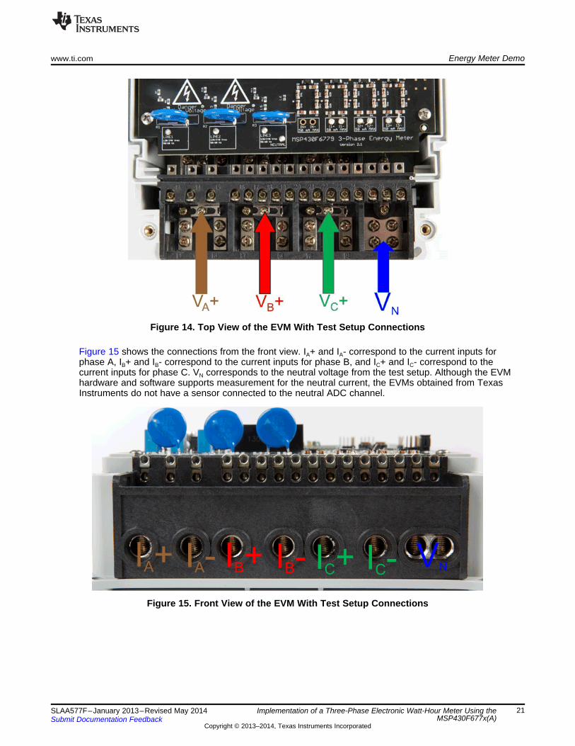
When a test ac source needs to be connected, the connections must be made according to the EVMdesign. Figure 14 shows the connections from the top view. VA+ , VB+, and VC+ corresponds to the linevoltage for phases A, B, and C, respectively. VN corresponds to the neutral voltage from the test acsource.
20 Implementation of a Three-Phase Electronic Watt-Hour Meter Using the SLAA577F–January 2013–Revised May 2014MSP430F677x(A) Submit Documentation Feedback
Copyright © 2013–2014, Texas Instruments Incorporated
www.ti.com Energy Meter Demo
Figure 14. Top View of the EVM With Test Setup Connections
Figure 15 shows the connections from the front view. IA+ and IA- correspond to the current inputs forphase A, IB+ and IB- correspond to the current inputs for phase B, and IC+ and IC- correspond to thecurrent inputs for phase C. VN corresponds to the neutral voltage from the test setup. Although the EVMhardware and software supports measurement for the neutral current, the EVMs obtained from TexasInstruments do not have a sensor connected to the neutral ADC channel.
Figure 15. Front View of the EVM With Test Setup Connections
21SLAA577F–January 2013–Revised May 2014 Implementation of a Three-Phase Electronic Watt-Hour Meter Using theMSP430F677x(A)Submit Documentation Feedback
Copyright © 2013–2014, Texas Instruments Incorporated
Energy Meter Demo www.ti.com
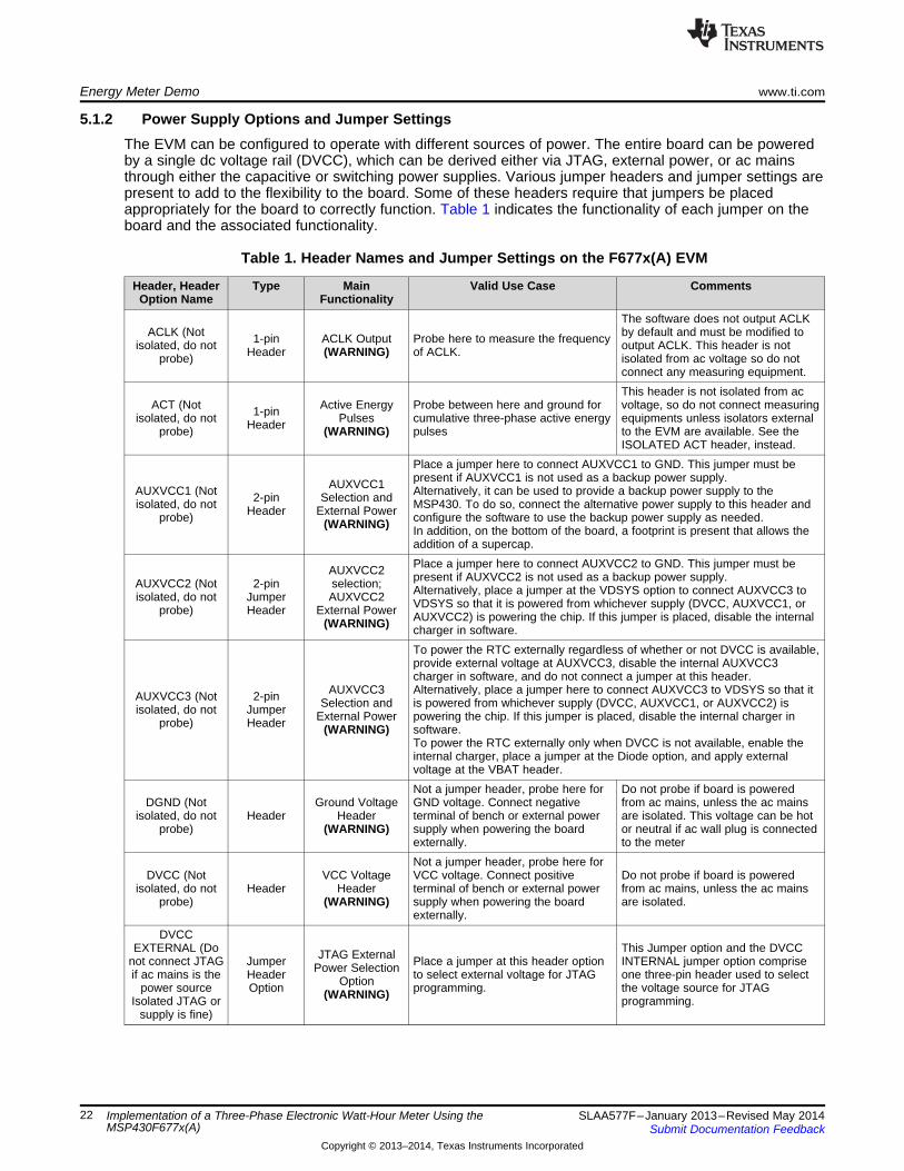
5.1.2 Power Supply Options and Jumper SettingsThe EVM can be configured to operate with different sources of power. The entire board can be poweredby a single dc voltage rail (DVCC), which can be derived either via JTAG, external power, or ac mainsthrough either the capacitive or switching power supplies. Various jumper headers and jumper settings arepresent to add to the flexibility to the board. Some of these headers require that jumpers be placedappropriately for the board to correctly function. Table 1 indicates the functionality of each jumper on theboard and the associated functionality.
Table 1. Header Names and Jumper Settings on the F677x(A) EVM
Header, Header Type Main Valid Use Case CommentsOption Name Functionality
The software does not output ACLKACLK (Not by default and must be modified to1-pin ACLK Output Probe here to measure the frequencyisolated, do not output ACLK. This header is notHeader (WARNING) of ACLK.probe) isolated from ac voltage so do not
connect any measuring equipment.This header is not isolated from ac
ACT (Not Active Energy Probe between here and ground for voltage, so do not connect measuring1-pinisolated, do not Pulses cumulative three-phase active energy equipments unless isolators externalHeaderprobe) (WARNING) pulses to the EVM are available. See theISOLATED ACT header, instead.
Place a jumper here to connect AUXVCC1 to GND. This jumper must bepresent if AUXVCC1 is not used as a backup power supply.AUXVCC1AUXVCC1 (Not Alternatively, it can be used to provide a backup power supply to the2-pin Selection andisolated, do not MSP430. To do so, connect the alternative power supply to this header andHeader External Powerprobe) configure the software to use the backup power supply as needed.(WARNING) In addition, on the bottom of the board, a footprint is present that allows theaddition of a supercap.Place a jumper here to connect AUXVCC2 to GND. This jumper must beAUXVCC2 present if AUXVCC2 is not used as a backup power supply.AUXVCC2 (Not 2-pin selection; Alternatively, place a jumper at the VDSYS option to connect AUXVCC3 toisolated, do not Jumper AUXVCC2 VDSYS so that it is powered from whichever supply (DVCC, AUXVCC1, orprobe) Header External Power AUXVCC2) is powering the chip. If this jumper is placed, disable the internal(WARNING) charger in software.To power the RTC externally regardless of whether or not DVCC is available,provide external voltage at AUXVCC3, disable the internal AUXVCC3charger in software, and do not connect a jumper at this header.
AUXVCC3 Alternatively, place a jumper here to connect AUXVCC3 to VDSYS so that itAUXVCC3 (Not 2-pin Selection and is powered from whichever supply (DVCC, AUXVCC1, or AUXVCC2) isisolated, do not Jumper External Power powering the chip. If this jumper is placed, disable the internal charger inprobe) Header (WARNING) software.To power the RTC externally only when DVCC is not available, enable theinternal charger, place a jumper at the Diode option, and apply externalvoltage at the VBAT header.Not a jumper header, probe here for Do not probe if board is powered
DGND (Not Ground Voltage GND voltage. Connect negative from ac mains, unless the ac mainsisolated, do not Header Header terminal of bench or external power are isolated. This voltage can be hot
probe) (WARNING) supply when powering the board or neutral if ac wall plug is connectedexternally. to the meterNot a jumper header, probe here for
DVCC (Not VCC Voltage VCC voltage. Connect positive Do not probe if board is poweredisolated, do not Header Header terminal of bench or external power from ac mains, unless the ac mains
probe) (WARNING) supply when powering the board are isolated.externally.
DVCCEXTERNAL (Do This Jumper option and the DVCCJTAG Externalnot connect JTAG Jumper Place a jumper at this header option INTERNAL jumper option comprisePower Selectionif ac mains is the Header to select external voltage for JTAG one three-pin header used to selectOptionpower source Option programming. the voltage source for JTAG(WARNING)Isolated JTAG or programming.supply is fine)
22 Implementation of a Three-Phase Electronic Watt-Hour Meter Using the SLAA577F–January 2013–Revised May 2014MSP430F677x(A) Submit Documentation Feedback
Copyright © 2013–2014, Texas Instruments Incorporated
www.ti.com Energy Meter Demo
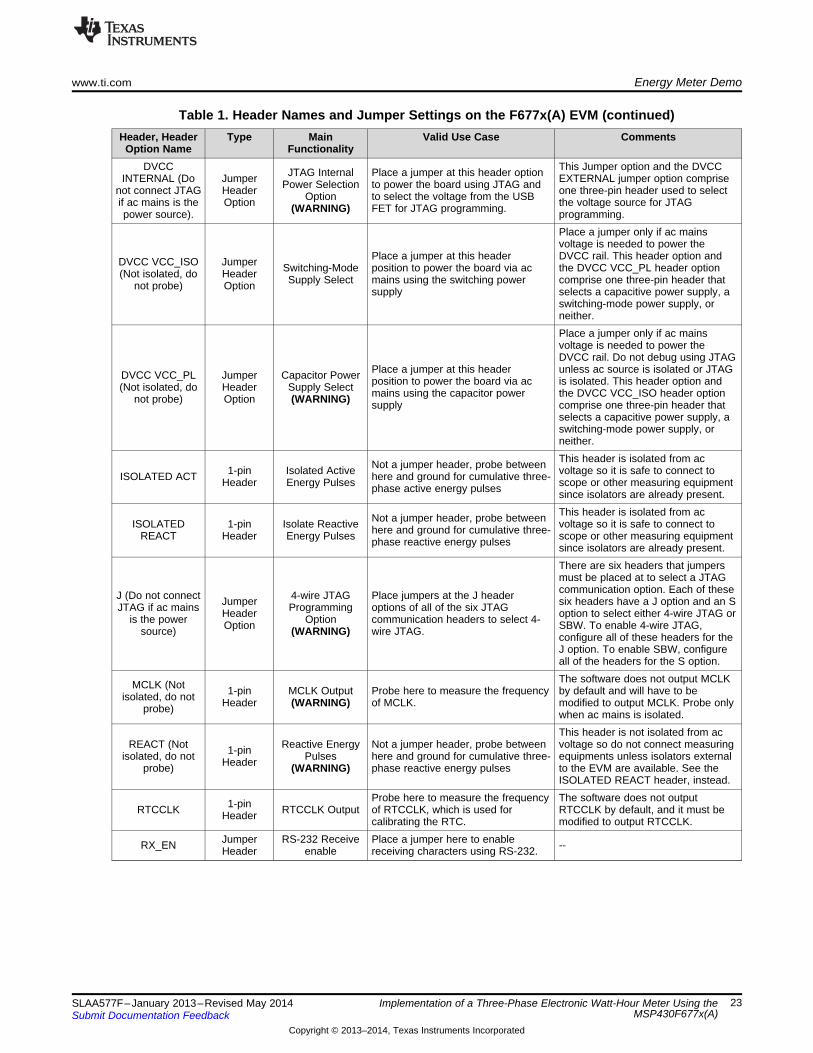
Table 1. Header Names and Jumper Settings on the F677x(A) EVM (continued)Header, Header Type Main Valid Use Case Comments
Option Name FunctionalityDVCC This Jumper option and the DVCCJTAG Internal Place a jumper at this header optionINTERNAL (Do Jumper EXTERNAL jumper option comprisePower Selection to power the board using JTAG andnot connect JTAG Header one three-pin header used to selectOption to select the voltage from the USBif ac mains is the Option the voltage source for JTAG(WARNING) FET for JTAG programming.power source). programming.
Place a jumper only if ac mainsvoltage is needed to power the
Place a jumper at this header DVCC rail. This header option andDVCC VCC_ISO Jumper Switching-Mode position to power the board via ac the DVCC VCC_PL header option(Not isolated, do Header Supply Select mains using the switching power comprise one three-pin header thatnot probe) Option supply selects a capacitive power supply, aswitching-mode power supply, orneither.Place a jumper only if ac mainsvoltage is needed to power theDVCC rail. Do not debug using JTAG
Place a jumper at this header unless ac source is isolated or JTAGDVCC VCC_PL Jumper Capacitor Power position to power the board via ac is isolated. This header option and(Not isolated, do Header Supply Select mains using the capacitor power the DVCC VCC_ISO header optionnot probe) Option (WARNING) supply comprise one three-pin header thatselects a capacitive power supply, aswitching-mode power supply, orneither.This header is isolated from acNot a jumper header, probe between1-pin Isolated Active voltage so it is safe to connect toISOLATED ACT here and ground for cumulative three-Header Energy Pulses scope or other measuring equipmentphase active energy pulses since isolators are already present.This header is isolated from acNot a jumper header, probe betweenISOLATED 1-pin Isolate Reactive voltage so it is safe to connect tohere and ground for cumulative three-REACT Header Energy Pulses scope or other measuring equipmentphase reactive energy pulses since isolators are already present.There are six headers that jumpersmust be placed at to select a JTAGcommunication option. Each of theseJ (Do not connect 4-wire JTAG Place jumpers at the J headerJumper six headers have a J option and an SJTAG if ac mains Programming options of all of the six JTAGHeader option to select either 4-wire JTAG oris the power Option communication headers to select 4-Option SBW. To enable 4-wire JTAG,source) (WARNING) wire JTAG. configure all of these headers for theJ option. To enable SBW, configureall of the headers for the S option.The software does not output MCLKMCLK (Not 1-pin MCLK Output Probe here to measure the frequency by default and will have to beisolated, do not Header (WARNING) of MCLK. modified to output MCLK. Probe onlyprobe) when ac mains is isolated.This header is not isolated from ac
REACT (Not Reactive Energy Not a jumper header, probe between voltage so do not connect measuring1-pinisolated, do not Pulses here and ground for cumulative three- equipments unless isolators externalHeaderprobe) (WARNING) phase reactive energy pulses to the EVM are available. See theISOLATED REACT header, instead.
Probe here to measure the frequency The software does not output1-pinRTCCLK RTCCLK Output of RTCCLK, which is used for RTCCLK by default, and it must beHeader calibrating the RTC. modified to output RTCCLK.Jumper RS-232 Receive Place a jumper here to enableRX_EN --Header enable receiving characters using RS-232.
23SLAA577F–January 2013–Revised May 2014 Implementation of a Three-Phase Electronic Watt-Hour Meter Using theMSP430F677x(A)Submit Documentation Feedback
Copyright © 2013–2014, Texas Instruments Incorporated

Energy Meter Demo www.ti.com
Table 1. Header Names and Jumper Settings on the F677x(A) EVM (continued)Header, Header Type Main Valid Use Case Comments
Option Name FunctionalityThere are six headers where jumpersmust be placed at to select a JTAGcommunication mode. Each of these
S (Do not SBW JTAG Place jumpers at the S header six headers that have a J option andJumperconnect JTAG if Programming options of all of the six JTAG an S option to select either 4-wireHeaderac mains is the Option communication headers to select JTAG or SBW. To enable 4-wireOptionpower source) (WARNING) SBW JTAG, all of these headers must beconfigured for the J option. To enableSBW, all of the headers must beconfigured for the S option.
SCL (Not 1-pin I2C/EEPROM Probe only when ac mains isisolated, do not Jumper SCL probe point Probe here to probe I2C SCL line isolated.probe) Header (WARNING)SDA (Not 1-pin I2C/EEPROM Probe only when ac mains isisolated, do not Jumper SDA probe point Probe here to probe I2C SDA line isolated.probe) Header (WARNING)
The software does not output MCLKSMCLK (Not 1-pin SMCLK Output Probe here to measure the frequency by default and must be modified toisolated, do not Header (WARNING) of SMCLK. output SMCLK. Probe only when acprobe) mains is isolated.Jumper RS-232 Transmit Place a jumper here to enable RS-TX_EN --Header Enable 232 transmissions.
AUXVCC32-pin External Power When the Diode option is selected for AUXVCC3, apply voltage at this
VBAT Jumper For AUXVCC3 header so that the RTC is still powered when the voltage at DVCC isHeader Diode Option removed.
(WARNING)
24 Implementation of a Three-Phase Electronic Watt-Hour Meter Using the SLAA577F–January 2013–Revised May 2014MSP430F677x(A) Submit Documentation Feedback
Copyright © 2013–2014, Texas Instruments Incorporated
www.ti.com Energy Meter Demo
5.2 Loading the Example CodeThe source code is developed in the IAR environment using IAR compiler version 6.x. Earlier versions ofIAR cannot open the project files. When the project is loaded in IAR version 6.x or later, the IDE promptsyou to create a backup. Click YES to proceed. There are three parts to the energy metrology software.• The toolkit that contains a library of mostly mathematics routines• The main code that is made of the source and include files• The GUI that is used for calibration
In this software package, there are two sets of directories: one for the MSP430F6779 and one for theMSP430F6779A. Depending on the utilized device, open the proper directory. Section 5.2.1 describeshow to compile a project for the MSP430F6779 option. A similar set of instructions can be followed tocompile a project for the MSP430F6779A option.
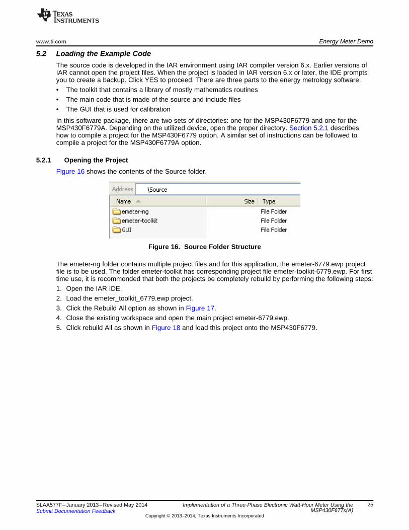
5.2.1 Opening the ProjectFigure 16 shows the contents of the Source folder.
Figure 16. Source Folder Structure
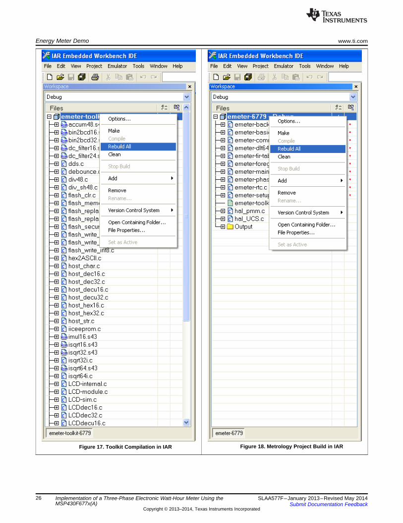
The emeter-ng folder contains multiple project files and for this application, the emeter-6779.ewp projectfile is to be used. The folder emeter-toolkit has corresponding project file emeter-toolkit-6779.ewp. For firsttime use, it is recommended that both the projects be completely rebuild by performing the following steps:1. Open the IAR IDE.2. Load the emeter_toolkit_6779.ewp project.3. Click the Rebuild All option as shown in Figure 17.4. Close the existing workspace and open the main project emeter-6779.ewp.5. Click rebuild All as shown in Figure 18 and load this project onto the MSP430F6779.
25SLAA577F–January 2013–Revised May 2014 Implementation of a Three-Phase Electronic Watt-Hour Meter Using theMSP430F677x(A)Submit Documentation Feedback
Copyright © 2013–2014, Texas Instruments Incorporated
Energy Meter Demo www.ti.com
Figure 18. Metrology Project Build in IARFigure 17. Toolkit Compilation in IAR
26 Implementation of a Three-Phase Electronic Watt-Hour Meter Using the SLAA577F–January 2013–Revised May 2014MSP430F677x(A) Submit Documentation Feedback
Copyright © 2013–2014, Texas Instruments Incorporated

www.ti.com Results and Calibration
6 Results and Calibration
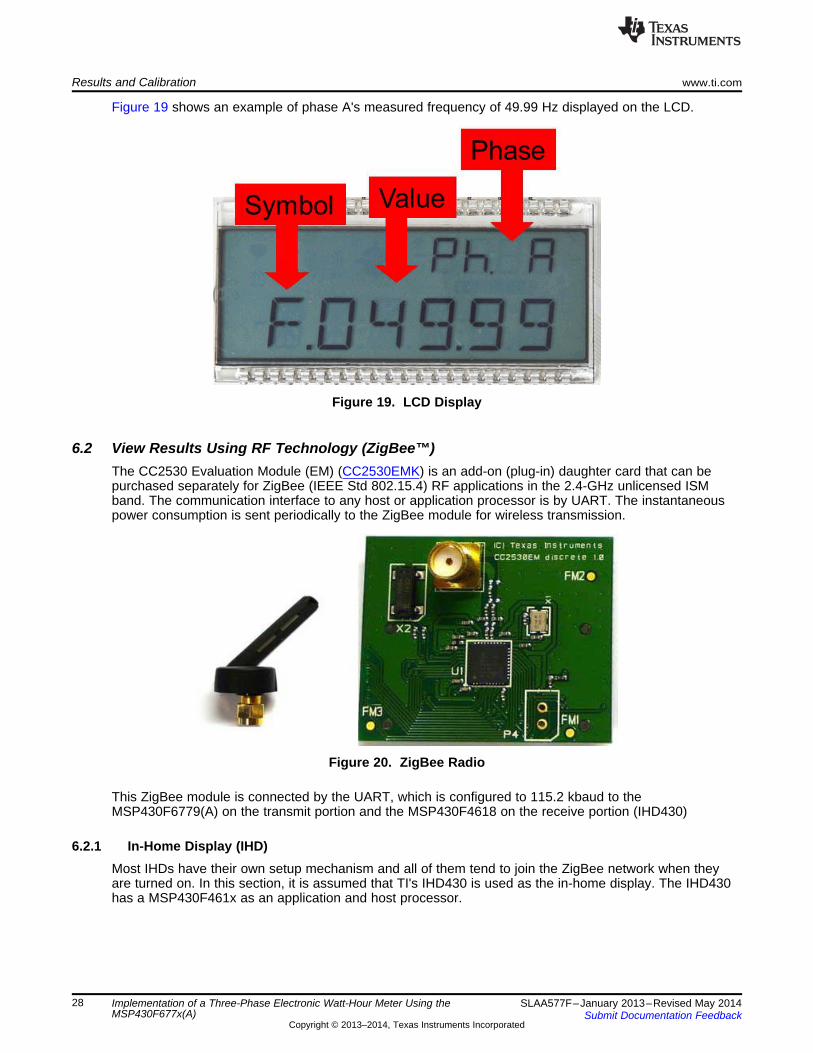
6.1 Viewing Results via LCDThe LCD display scrolls between metering parameter approximately every two seconds. For eachmetering parameter that is displayed on the LCD, three items are actually displayed on the screen: thecorresponding phase of the parameter, a one or two character symbol used to distinguish whichparameter is being displayed, and the actual value of the parameter. The phase of the parameter isdisplayed on the top line of the LCD. This may take the values of A, B, C, and t for phase A, phase B,phase C, and the aggregate-sum of these phases, respectively. The parameter symbol is displayed on theleft of the second line of the LCD. To the right of the parameter symbol is the actual value of theparameter.
Table 2 shows the different metering parameters that are displayed on the LCD and the associated unitsin which they are displayed. The Symbol column shows which characters correspond to which meteringparameter. The Comments column provides a brief interpretation of the displayed metering parameters.
Table 2. Displayed Parameters
Parameter Name Symbol Units Comments
Voltage Volts (V) --
Current Amps (A)
Active Power Watt (W) --
Reactive Power Volt-Ampere Reactive (var) --
Apparent Power Volt-Ampere (VA) --
Frequency Hertz (Hz) --
The characters are used if the load isdetermined to be a capacitive load.Power Factor Constant between 0 and 1
The characters are used if the load isdetermined to be an inductive load.
Total Consumed 100 "Tick" Every 10 ticks increments the tenths place by 1.Active Energy
Total Consumed 100 "Tick" Every 10 ticks increments the tenths place by 1.Reactive Energy
27SLAA577F–January 2013–Revised May 2014 Implementation of a Three-Phase Electronic Watt-Hour Meter Using theMSP430F677x(A)Submit Documentation Feedback
Copyright © 2013–2014, Texas Instruments Incorporated
Results and Calibration www.ti.com
Figure 19 shows an example of phase A's measured frequency of 49.99 Hz displayed on the LCD.
Figure 19. LCD Display
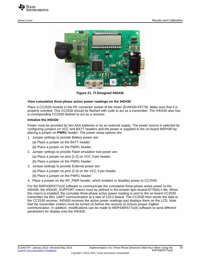
6.2 View Results Using RF Technology (ZigBee™)The CC2530 Evaluation Module (EM) (CC2530EMK) is an add-on (plug-in) daughter card that can bepurchased separately for ZigBee (IEEE Std 802.15.4) RF applications in the 2.4-GHz unlicensed ISMband. The communication interface to any host or application processor is by UART. The instantaneouspower consumption is sent periodically to the ZigBee module for wireless transmission.
Figure 20. ZigBee Radio
This ZigBee module is connected by the UART, which is configured to 115.2 kbaud to theMSP430F6779(A) on the transmit portion and the MSP430F4618 on the receive portion (IHD430)
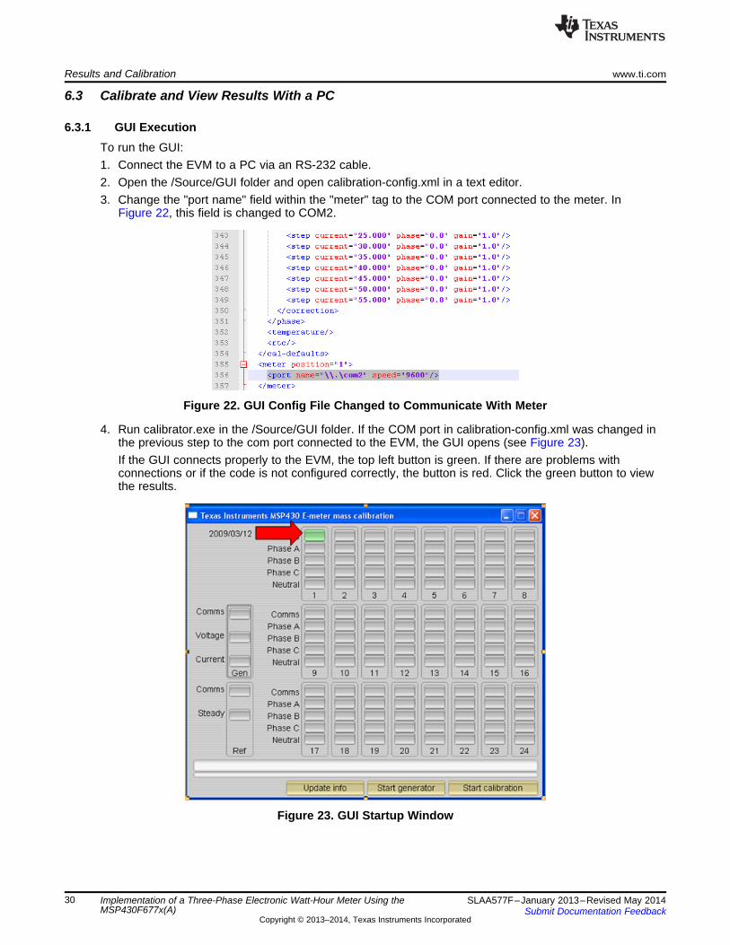
6.2.1 In-Home Display (IHD)Most IHDs have their own setup mechanism and all of them tend to join the ZigBee network when theyare turned on. In this section, it is assumed that TI's IHD430 is used as the in-home display. The IHD430has a MSP430F461x as an application and host processor.
28 Implementation of a Three-Phase Electronic Watt-Hour Meter Using the SLAA577F–January 2013–Revised May 2014MSP430F677x(A) Submit Documentation Feedback
Copyright © 2013–2014, Texas Instruments Incorporated
www.ti.com Results and Calibration
Figure 21. TI Designed IHD430
View cumulative three-phase active power readings on the IHD430Place a CC2530 module in the RF connector socket of the meter (EVM430-F6779). Make sure that it isproperly oriented. This CC2530 should be flashed with code to act as a transmitter. The IHD430 also hasa corresponding CC2530 flashed to act as a receiver.
Initialize the IHD430Power must be provided by two AAA batteries or by an external supply. The power source is selected byconfiguring jumpers on VCC and BATT headers and the power is supplied to the on-board MSP430 byplacing a jumper on PWR1 header. The power setup options are:1. Jumper settings to provide Battery power are:
(a) Place a jumper on the BATT header.(b) Place a jumper on the PWR1 header.
2. Jumper settings to provide Flash emulation tool power are:(a) Place a jumper on pins [1-2] on VCC 3-pin header.(b) Place a jumper on the PWR1 header.
3. Jumper settings to provide External power are:(a) Place a jumper on pins [2-3] on the VCC 3-pin header.(b) Place a jumper on the PWR1 header.
4. Place a jumper on the RF_PWR header, which enables or disables power to CC2530.
For the MSP430F677x(A) software to communicate the cumulative three-phase active power to theIHD430, the IHD430_SUPPORT macro must be defined in the emeter-3ph-neutral-6779(A).h file. Whenthis macro is enabled, the cumulate three-phase active power reading is sent to the on-board CC2530transmitter via 8N1 UART communication at a rate of 115.2 kbaud. The CC2530 then sends the data tothe CC2530 receiver. IHD430 receives the active power readings and displays them on the LCD. Notethat the transmitter (meter) must be turned on before the receiver to ensure proper ZigBeecommunication. In addition, modifications can be made to MSP430F677x(A) software to send differentparameters for display onto the IHD430.
29SLAA577F–January 2013–Revised May 2014 Implementation of a Three-Phase Electronic Watt-Hour Meter Using theMSP430F677x(A)Submit Documentation Feedback
Copyright © 2013–2014, Texas Instruments Incorporated
Results and Calibration www.ti.com
6.3 Calibrate and View Results With a PC
6.3.1 GUI ExecutionTo run the GUI:1. Connect the EVM to a PC via an RS-232 cable.2. Open the /Source/GUI folder and open calibration-config.xml in a text editor.3. Change the "port name" field within the "meter" tag to the COM port connected to the meter. In
Figure 22, this field is changed to COM2.
Figure 22. GUI Config File Changed to Communicate With Meter
4. Run calibrator.exe in the /Source/GUI folder. If the COM port in calibration-config.xml was changed inthe previous step to the com port connected to the EVM, the GUI opens (see Figure 23).If the GUI connects properly to the EVM, the top left button is green. If there are problems withconnections or if the code is not configured correctly, the button is red. Click the green button to viewthe results.
Figure 23. GUI Startup Window
30 Implementation of a Three-Phase Electronic Watt-Hour Meter Using the SLAA577F–January 2013–Revised May 2014MSP430F677x(A) Submit Documentation Feedback
Copyright © 2013–2014, Texas Instruments Incorporated
www.ti.com Results and Calibration
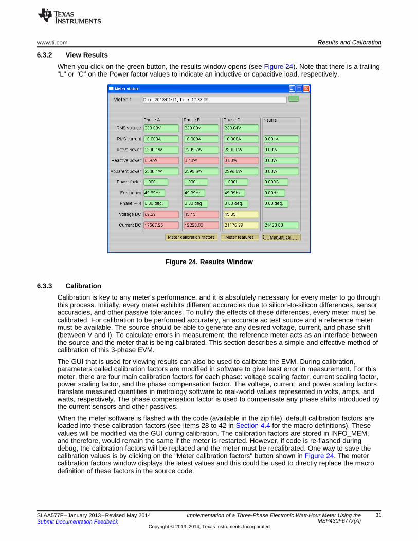
6.3.2 View ResultsWhen you click on the green button, the results window opens (see Figure 24). Note that there is a trailing"L" or "C" on the Power factor values to indicate an inductive or capacitive load, respectively.
Figure 24. Results Window
6.3.3 CalibrationCalibration is key to any meter's performance, and it is absolutely necessary for every meter to go throughthis process. Initially, every meter exhibits different accuracies due to silicon-to-silicon differences, sensoraccuracies, and other passive tolerances. To nullify the effects of these differences, every meter must becalibrated. For calibration to be performed accurately, an accurate ac test source and a reference metermust be available. The source should be able to generate any desired voltage, current, and phase shift(between V and I). To calculate errors in measurement, the reference meter acts as an interface betweenthe source and the meter that is being calibrated. This section describes a simple and effective method ofcalibration of this 3-phase EVM.
The GUI that is used for viewing results can also be used to calibrate the EVM. During calibration,parameters called calibration factors are modified in software to give least error in measurement. For thismeter, there are four main calibration factors for each phase: voltage scaling factor, current scaling factor,power scaling factor, and the phase compensation factor. The voltage, current, and power scaling factorstranslate measured quantities in metrology software to real-world values represented in volts, amps, andwatts, respectively. The phase compensation factor is used to compensate any phase shifts introduced bythe current sensors and other passives.
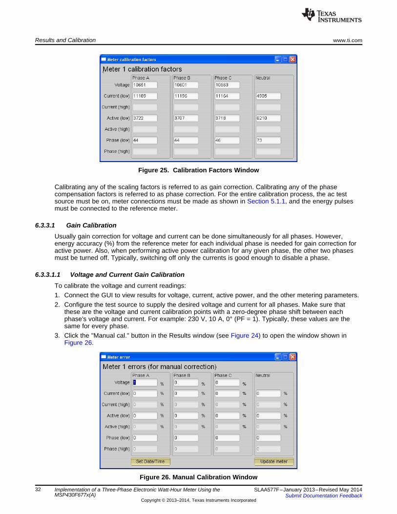
When the meter software is flashed with the code (available in the zip file), default calibration factors areloaded into these calibration factors (see items 28 to 42 in Section 4.4 for the macro definitions). Thesevalues will be modified via the GUI during calibration. The calibration factors are stored in INFO_MEM,and therefore, would remain the same if the meter is restarted. However, if code is re-flashed duringdebug, the calibration factors will be replaced and the meter must be recalibrated. One way to save thecalibration values is by clicking on the "Meter calibration factors" button shown in Figure 24. The metercalibration factors window displays the latest values and this could be used to directly replace the macrodefinition of these factors in the source code.
31SLAA577F–January 2013–Revised May 2014 Implementation of a Three-Phase Electronic Watt-Hour Meter Using theMSP430F677x(A)Submit Documentation Feedback
Copyright © 2013–2014, Texas Instruments Incorporated
Results and Calibration www.ti.com
Figure 25. Calibration Factors Window
Calibrating any of the scaling factors is referred to as gain correction. Calibrating any of the phasecompensation factors is referred to as phase correction. For the entire calibration process, the ac testsource must be on, meter connections must be made as shown in Section 5.1.1, and the energy pulsesmust be connected to the reference meter.
6.3.3.1 Gain CalibrationUsually gain correction for voltage and current can be done simultaneously for all phases. However,energy accuracy (%) from the reference meter for each individual phase is needed for gain correction foractive power. Also, when performing active power calibration for any given phase, the other two phasesmust be turned off. Typically, switching off only the currents is good enough to disable a phase.
6.3.3.1.1 Voltage and Current Gain CalibrationTo calibrate the voltage and current readings:1. Connect the GUI to view results for voltage, current, active power, and the other metering parameters.2. Configure the test source to supply the desired voltage and current for all phases. Make sure that
these are the voltage and current calibration points with a zero-degree phase shift between eachphase's voltage and current. For example: 230 V, 10 A, 0° (PF = 1). Typically, these values are thesame for every phase.
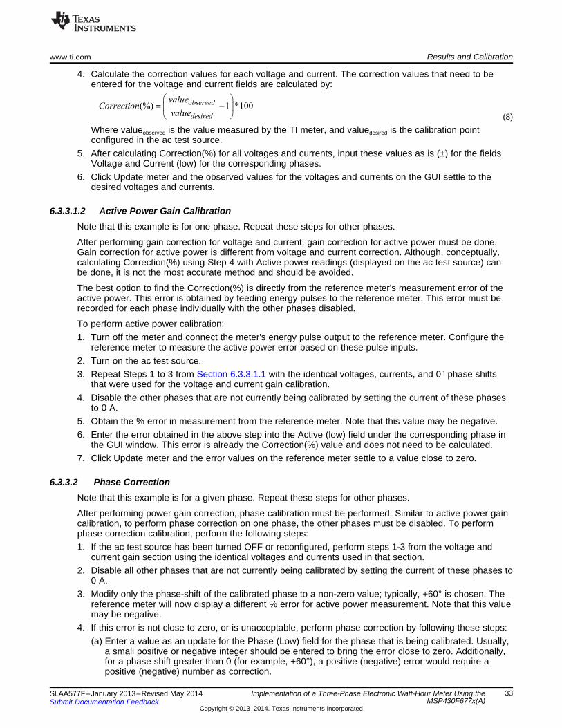
3. Click the "Manual cal." button in the Results window (see Figure 24) to open the window shown inFigure 26.
Figure 26. Manual Calibration Window
32 Implementation of a Three-Phase Electronic Watt-Hour Meter Using the SLAA577F–January 2013–Revised May 2014MSP430F677x(A) Submit Documentation Feedback
Copyright © 2013–2014, Texas Instruments Incorporated
(%) –1 *100observed
desired
valueCorrection
value
æ ö= ç ÷
è ø
www.ti.com Results and Calibration
4. Calculate the correction values for each voltage and current. The correction values that need to beentered for the voltage and current fields are calculated by:
(8)Where valueobserved is the value measured by the TI meter, and valuedesired is the calibration pointconfigured in the ac test source.
5. After calculating Correction(%) for all voltages and currents, input these values as is (±) for the fieldsVoltage and Current (low) for the corresponding phases.
6. Click Update meter and the observed values for the voltages and currents on the GUI settle to thedesired voltages and currents.
6.3.3.1.2 Active Power Gain CalibrationNote that this example is for one phase. Repeat these steps for other phases.
After performing gain correction for voltage and current, gain correction for active power must be done.Gain correction for active power is different from voltage and current correction. Although, conceptually,calculating Correction(%) using Step 4 with Active power readings (displayed on the ac test source) canbe done, it is not the most accurate method and should be avoided.
The best option to find the Correction(%) is directly from the reference meter's measurement error of theactive power. This error is obtained by feeding energy pulses to the reference meter. This error must berecorded for each phase individually with the other phases disabled.
To perform active power calibration:1. Turn off the meter and connect the meter's energy pulse output to the reference meter. Configure the
reference meter to measure the active power error based on these pulse inputs.2. Turn on the ac test source.3. Repeat Steps 1 to 3 from Section 6.3.3.1.1 with the identical voltages, currents, and 0° phase shifts
that were used for the voltage and current gain calibration.4. Disable the other phases that are not currently being calibrated by setting the current of these phases
to 0 A.5. Obtain the % error in measurement from the reference meter. Note that this value may be negative.6. Enter the error obtained in the above step into the Active (low) field under the corresponding phase in
the GUI window. This error is already the Correction(%) value and does not need to be calculated.7. Click Update meter and the error values on the reference meter settle to a value close to zero.
6.3.3.2 Phase CorrectionNote that this example is for a given phase. Repeat these steps for other phases.
After performing power gain correction, phase calibration must be performed. Similar to active power gaincalibration, to perform phase correction on one phase, the other phases must be disabled. To performphase correction calibration, perform the following steps:1. If the ac test source has been turned OFF or reconfigured, perform steps 1-3 from the voltage and
current gain section using the identical voltages and currents used in that section.2. Disable all other phases that are not currently being calibrated by setting the current of these phases to
0 A.3. Modify only the phase-shift of the calibrated phase to a non-zero value; typically, +60° is chosen. The
reference meter will now display a different % error for active power measurement. Note that this valuemay be negative.
4. If this error is not close to zero, or is unacceptable, perform phase correction by following these steps:(a) Enter a value as an update for the Phase (Low) field for the phase that is being calibrated. Usually,
a small positive or negative integer should be entered to bring the error close to zero. Additionally,for a phase shift greater than 0 (for example, +60°), a positive (negative) error would require apositive (negative) number as correction.
33SLAA577F–January 2013–Revised May 2014 Implementation of a Three-Phase Electronic Watt-Hour Meter Using theMSP430F677x(A)Submit Documentation Feedback
Copyright © 2013–2014, Texas Instruments Incorporated
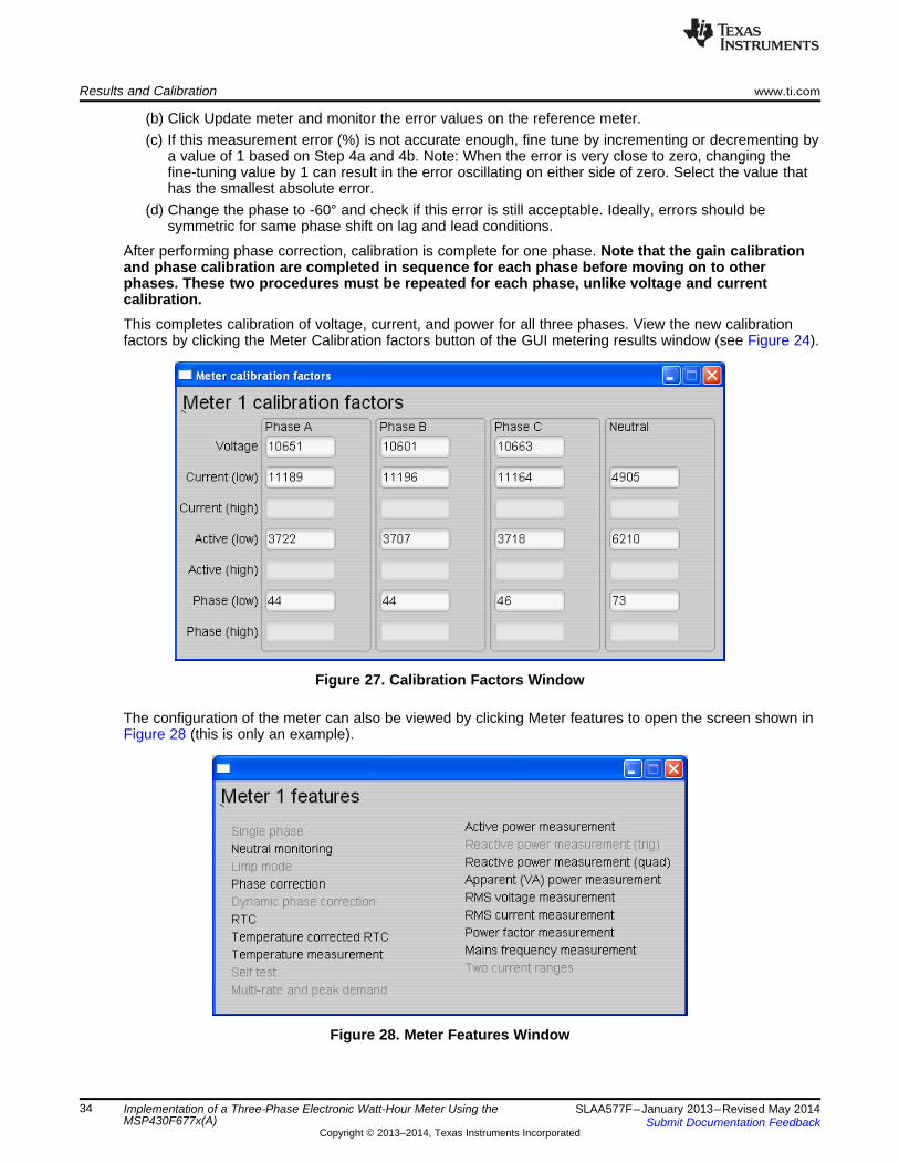
Results and Calibration www.ti.com
(b) Click Update meter and monitor the error values on the reference meter.(c) If this measurement error (%) is not accurate enough, fine tune by incrementing or decrementing by
a value of 1 based on Step 4a and 4b. Note: When the error is very close to zero, changing thefine-tuning value by 1 can result in the error oscillating on either side of zero. Select the value thathas the smallest absolute error.
(d) Change the phase to -60° and check if this error is still acceptable. Ideally, errors should besymmetric for same phase shift on lag and lead conditions.
After performing phase correction, calibration is complete for one phase. Note that the gain calibrationand phase calibration are completed in sequence for each phase before moving on to otherphases. These two procedures must be repeated for each phase, unlike voltage and currentcalibration.This completes calibration of voltage, current, and power for all three phases. View the new calibrationfactors by clicking the Meter Calibration factors button of the GUI metering results window (see Figure 24).
Figure 27. Calibration Factors Window
The configuration of the meter can also be viewed by clicking Meter features to open the screen shown inFigure 28 (this is only an example).
Figure 28. Meter Features Window
34 Implementation of a Three-Phase Electronic Watt-Hour Meter Using the SLAA577F–January 2013–Revised May 2014MSP430F677x(A) Submit Documentation Feedback
Copyright © 2013–2014, Texas Instruments Incorporated

www.ti.com Results and Calibration
6.3.4 Metrology ResultsIn this section, metrology results are shown for cumulative three-phase active energy. Figure 29 showsthe results over a dynamic range of 2000:1 using the customized CTs that are provided with the EVM430-F6779. Table 3 shows the values for the error. Changing the EVM's CTs may result in better performance.Figure 30 shows the results over the same dynamic range using high-end CTs over the same currentrange. Table 4 shows the values for the error. All results were calibrated at 230 V, 10 A, 50 Hz.
Figure 29. Energy Measurement Error Across Current With Customized CTs on EVM430-F6779
Table 3. Energy Measurement Error With CustomizedCTs on EVM430-F6779 (%)
Current 0° 60° -60°(A)0.05 -0.02 0.0445 -0.1470.1 -0.011 0.093 -0.13730.25 -0.0173 0.073 -0.1310.5 -0.0187 0.0877 -0.12771 -0.0173 0.0853 -0.10772 -0.0157 0.0815 -0.12035 -0.014 0.0627 -0.088710 -0.006 0.0497 -0.063320 -0.0073 0.0377 -0.04930 -0.001 0.018 -0.03740 0.0003 0.026 -0.02750 -0.006 -0.0197 0.001360 -0.007 -0.04 0.029770 -0.003 -0.0533 0.04180 -0.0083 -0.0613 0.04990 -0.0093 -0.0707 0.053100 -0.0177 -0.0763 0.0497
35SLAA577F–January 2013–Revised May 2014 Implementation of a Three-Phase Electronic Watt-Hour Meter Using theMSP430F677x(A)Submit Documentation Feedback
Copyright © 2013–2014, Texas Instruments Incorporated
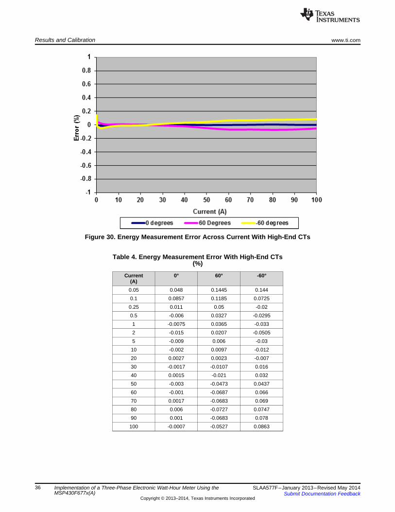
Results and Calibration www.ti.com
Figure 30. Energy Measurement Error Across Current With High-End CTs
Table 4. Energy Measurement Error With High-End CTs(%)
Current 0° 60° -60°(A)0.05 0.048 0.1445 0.1440.1 0.0857 0.1185 0.07250.25 0.011 0.05 -0.020.5 -0.006 0.0327 -0.02951 -0.0075 0.0365 -0.0332 -0.015 0.0207 -0.05055 -0.009 0.006 -0.0310 -0.002 0.0097 -0.01220 0.0027 0.0023 -0.00730 -0.0017 -0.0107 0.01640 0.0015 -0.021 0.03250 -0.003 -0.0473 0.043760 -0.001 -0.0687 0.06670 0.0017 -0.0683 0.06980 0.006 -0.0727 0.074790 0.001 -0.0683 0.078100 -0.0007 -0.0527 0.0863
36 Implementation of a Three-Phase Electronic Watt-Hour Meter Using the SLAA577F–January 2013–Revised May 2014MSP430F677x(A) Submit Documentation Feedback
Copyright © 2013–2014, Texas Instruments Incorporated
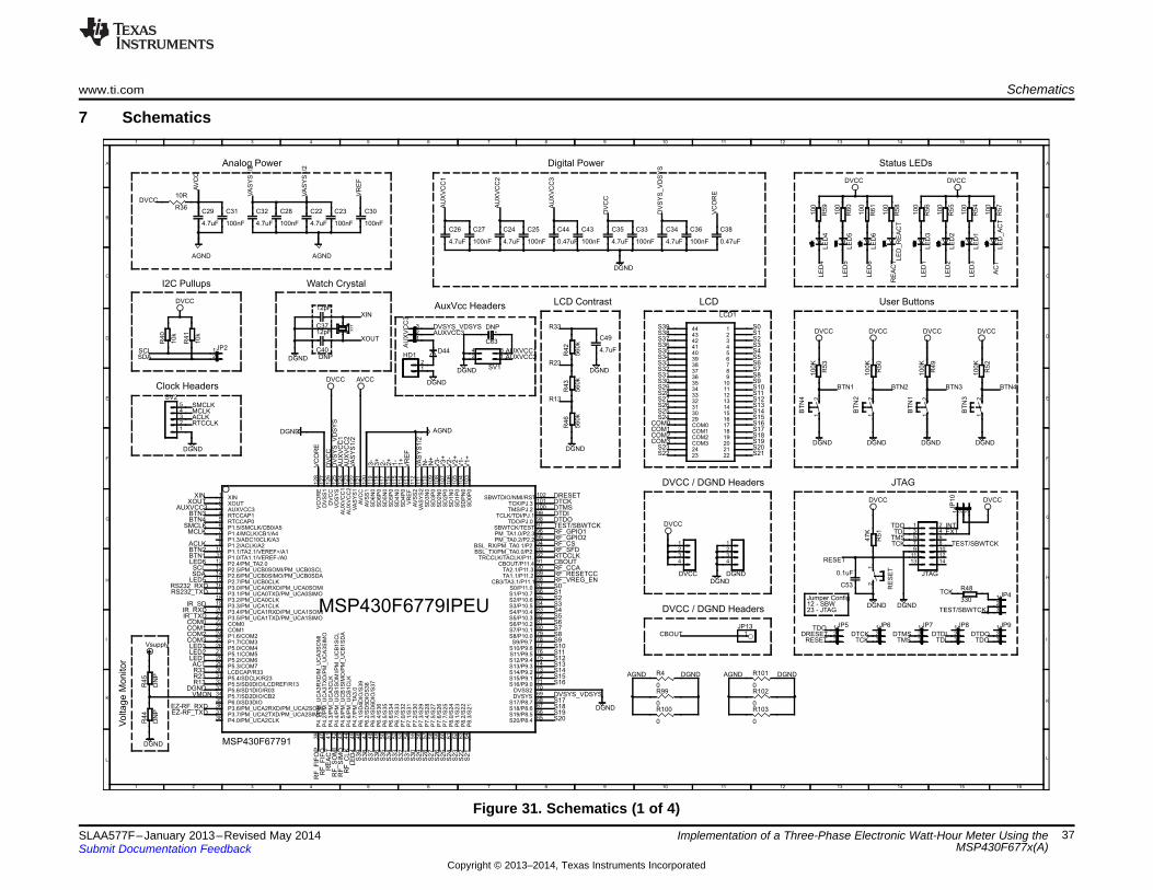
Clock Headers
AuxVcc Headers LCD Contrast
Watch Crystal
Analog Power Digital Power
Voltage M
onitor
Status LEDs
User ButtonsLCD
I2C Pullups
JTAG
23 - JTAG12 - SBWJumper Config
DVCC / DGND Headers
DVCC / DGND Headers
100K
100K
100
47K
12pF
12pF
100
0.1uF
100
100
DGND
DGND
DVCC
DVCC DVCC
DGND
DGND
DVCC
DGND
DVCC
4.7uF
4.7uF
4.7uF 4.7uF 0.47uF 4.7uF
4.7uF
0.47uF
4.7uF
DGND
DGND
DGND
100nF
AVCC
AGND
AGND
100nF 100nF 100nF
100nF100nF
AGND
10R
DGND
100
100
100
100
DGND
100K
100K
DVCC
DGND
DVCC
DGNDDGND
560k
560k
560k
DN
PD
NP
DGND
Vsupply
10k
10k
DVCC
330
100nF 100nF 100nF
DVCC DVCC
DGND
DVCC
4.7uF
DGND
DNP
0
0
0
0
0
0
DGND
DNP
13579
JTAG
1113
246
1214
810
R53
R50
R56
R51
C40
C37
R55
C53
R54
R57
XT
1
1 2 3
JP
10XIN1
XOUT2
AUXVCC33
RTCCAP14
RTCCAP05
P1.5/SMCLK/CB0/A56
P1.4/MCLK/CB1/A47
P1.3/ADC10CLK/A38
P1.2/ACLK/A29
P1.1/TA2.1/VEREF+/A110
P1.0/TA1.1/VEREF-/A011
P2.4/PM_TA2.012
P2.5/PM_UCB0SOMI/PM_UCB0SCL13
P2.6/PM_UCB0SIMO/PM_UCB0SDA14
P2.7/PM_UCB0CLK15
P3.0/PM_UCA0RXD/PM_UCA0SOMI16
P3.1/PM_UCA0TXD/PM_UCA0SIMO17
P3.2/PM_UCA0CLK18
P3.3/PM_UCA1CLK19
P3.4/PM_UCA1RXD/PM_UCA1SOMI20
P3.5/PM_UCA1TXD/PM_UCA1SIMO21
COM022
COM123
P1.6/COM224
P1.7/COM325
P5.0/COM426
P5.1/COM527
P5.2/COM628
P5.3/COM729
LCDCAP/R3330
P5.4/SDCLK/R2331
P5.5/SD0DIO/LCDREF/R1332
P5.6/SD1DIO/R0333
P5.7/SD2DIO/CB234
P6.0/SD3DIO35
P3.6/PM_UCA2RXD/PM_UCA2SOMI36
P3.7/PM_UCA2TXD/PM_UCA2SIMO37
P4.0/PM_UCA2CLK38
P4
.1/P
M_
UC
A3
RX
D/M
_U
CA
3S
OM
I3
9
P4
.2/P
M_
UC
A3
TX
D/P
M_
UC
A3
SIM
O4
0
P4
.3/P
M_
UC
A3
CL
K4
1
P4
.4/P
M_
UC
B1
SO
MI/
PM
_U
CB
1S
CL
42
P4
.5/P
M_
UC
B1
SIM
O/P
M_
UC
B1
SD
A4
3
P4
.6/P
M_
UC
B1
CL
K4
4
P4
.7/P
M_
TA
3.0
45
P6
.1/S
D4
DIO
/S3
94
6
P6
.2/S
D5
DIO
S3
84
7
P6
.3/S
D6
DIO
/S3
74
8
P6
.4/S
36
49
P6
.5/S
35
50
P6
.6/S
34
51
P6
.7/S
33
52
P7
.0/S
32
53
P7
.1/S
31
54
P7
.2/S
30
55
P7
.3/S
29
56
P7
.4/S
28
57
P7
.5/S
27
58
P7
.6/S
26
59
P7
.7/S
25
60
P8
.0/S
24
61
P8
.1/S
23
62
P8
.2/S
22
63
P8
.3/S
21
64
S20/P8.4 65S19/P8.5 66S18/P8.6 67S17/P8.7 68
DVSYS 69DVSS2 70
S16/P9.0 71S15/P9.1 72S14/P9.2 73S13/P9.3 74S12/P9.4 75S11/P9.5 76S10/P9.6 77S9/P9.7 78
S8/P10.0 79S7/P10.1 80S6/P10.2 81S5/P10.3 82S4/P10.4 83S3/P10.5 84S2/P10.6 85S1/P10.7 86S0/P11.0 87
CB3/TA3.1/P11.1 88TA1.1/P11.2 89TA2.1/P11.3 90
CBOUT/P11.4 91TRCCLK/TACLK/P11.592
BSL_TX/PM_TA0.0/P2.093BSL_RX/PM_TA0.1/P2.194
PM_TA0.2/P2.2 95PM_TA1.0/P2.3 96SBWTCK/TEST 97
TDO/PJ.0 98TCLK/TDI/PJ.1 99
TMS/PJ.2 100TCK/PJ.3 101
SBWTDIO/NMI/RST102
SD
0P
01
03
SD
PN
01
04
SD
1P
01
05
SD
1N
01
06
SD
2P
01
07
SD
2N
01
08
SD
3P
01
09
SD
3N
011
0V
AS
YS
2111
AV
SS
211
2V
RE
F11
3S
D4
P0
11
4S
D4
N0
11
5S
D5
P0
11
6S
D5
N0
11
7S
D6
P0
11
8S
D6
N0
11
9A
VS
S1
12
0A
VC
C1
21
VA
SY
S1
12
2A
UX
VC
C2
12
3A
UX
VC
C1
12
4V
DS
YS
12
5D
VC
C1
26
DV
SS
11
27
VC
OR
E1
28
123456789
10111213141516171819202122
44434241403938373635343332313029COM0COM1COM2COM32423
LCD1
C35
C29
C26 C24 C44 C34
C32
C38
C22 C30C31 C28 C23
C36C33
R36
12
SV1
34
R59
R60
R61
R58
12345
SV2
R49
R52
R42
R43
R46
R45
R44
R40
R41
123
JP4
123
JP5 123
JP6 123
JP7 123
JP8 123
JP9
R48
C27 C25 C43
1JP2
2
LE
D_A
CT
LE
D1
LE
D2
LE
D3
LE
D_R
EA
CT
LE
D4
LE
D5
LE
D6
1234
DGND
1234
DVCC
C49
12
BT
N4
12
BT
N2
12
BT
N1
12
BT
N3
12
RE
SE
T
1JP13
C63
R4
R99
R100
R101
R102
R103
123
AU
XV
CC
3
12
HD1D44
TDO
TDO
TDO
TDI
TDI
TMS
TMS
TCK
TCK
TCK
S4
S4
S5
S5
S6
S6
S7
S7
S10
S10
S11
S11
S12
S12
S13
S13
S14
S14
S15
S15
S16
S16
S17
S17
S18
S18
S19
S19
S20
S20
S21
S21
COM0
COM0
COM1
COM1
COM2
COM2
COM3
COM3
S8
S8
S9
S9
R13
R13
R23
R23
R33
R33
S22S
22
S23S
23
S1
S1
VR
EF
VR
EF
S0
S0
S2
S2
S3
S3
AV
CC
AGND AGND
DGND
DGND DGND
DV
CC
DVCC
DV
CC
V1+
V1-
I1+
I1-
I2+
I2-
V2+
V2-
V3+
V3-
I3+
I3-
IN+
IN-
INTEXT
S39
S39
S38
S38
S37
S37
S36
S36
S35
S35
S34
S34
S33
S33
S32
S32
S31
S31
S30
S30
S29
S29
S28
S28
S27
S27
S26
S26
S25
S25
S24
S24
RESET
RESET
BTN1
BTN1
BTN2
BTN2
LE
D1
LED1
LE
D2
LED2
LE
D3
LED3
LE
D4
LE
D4
VA
SY
S1/2
VA
SY
S1/2
VA
SY
S1/2
VA
SY
S1/2
VC
OR
E
VC
OR
E
AU
XV
CC
1
AU
XV
CC
1
AUXVCC1
AU
XV
CC
2
AU
XV
CC
2
AUXVCC2
AU
XV
CC
3
AUXVCC3
AUXVCC3
DVSYS_VDSYS
DV
SY
S_V
DS
YS
DV
SY
S_V
DS
YS
DVSYS_VDSYS
RS232_RXDRS232_TXD
EZ-RF_RXDEZ-RF_TXD
SDA
SDA
SCL
SCL
AC
T
ACT
RE
AC
T
RE
AC
T
LE
D6
LED6
LE
D5
LED5
SMCLK
SMCLK
MCLK
MCLK
ACLK
ACLK
IR_TXDIR_RXD
IR_SD
BTN3
BTN3
BTN4
BTN4
XOUT
XOUT
XIN
XIN
DRESET
DRESET
DTCK
DTCK
DTMS
DTMS
DTDI
DTDI
DTDO
DTDO
TEST/SBWTCK
TEST/SBWTCK
TEST/SBWTCK
RF
_S
OM
IR
F_S
IMO
RF
_C
LK
RF_VREG_ENRF_RESETCCRF_CCA
RF_SFD
RF_GPIO1RF_GPIO2RF_CS
RF
_F
IFO
PR
F_F
IFO
CBOUT
CBOUT
VMON
RTCCLK
RTCCLK
1 2 3 4 5 6 7 8 9 10 11 12 13 14 15 16
L
K
I
H
G
F
E
D
C
B
A
16151413121110987654321
A
B
C
D
E
F
G
H
I
K
L
MSP430F67791
MSP430F6779IPEU
+
www.ti.com Schematics
7 Schematics
Figure 31. Schematics (1 of 4)
37SLAA577F–January 2013–Revised May 2014 Implementation of a Three-Phase Electronic Watt-Hour Meter Using theMSP430F677x(A)Submit Documentation Feedback
Copyright © 2013–2014, Texas Instruments Incorporated
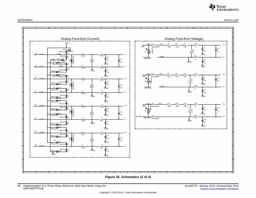
Analog Front-End (Voltage)Analog Front-End (Current)
0
0
47p
47p
47p
47p
47p
47p
47p
47p
15n
15n
15n
15n
AGND
AGND
AGND
AGND
AGND
AGND
AGND
AGND
0
0
AVCC
330k 330k 330k
2.3
7K
1k
330k 330k 330k
2.3
7K
1k
1k
12
.41
2.4
1k
1k
1k
1k
1k
S2
0K
27
5S
20
K2
75
PMLL4148
PMLL4148
PMLL4148
PMLL4148
PMLL4148
PMLL4148
PMLL4148
EXCML20A
EXCML20A
SM
AJ5
.0C
AS
MA
J5
.0C
A
0
47p
47p
15n
AGND
AGND
0
12
.4
1k
1k
PMLL4148
PMLL4148
PMLL4148
PMLL4148
SM
AJ5
.0C
A
47p
47p
15n
AGND
AGND
330k 330k 330k
2.3
7K
1k
1k
S2
0K
27
5
EXCML20A
EXCML20A
0
47p
47p
15n
AGND
AGND
AGND
0
12
.4
1k
1k
PMLL4148
PMLL4148
PMLL4148
PMLL4148
SM
AJ5
.0C
A
AGND
AGND
AGND
AGND
AGND
AGND
AGND
PMLL4148
PMLL4148
PMLL4148
PMLL4148
PMLL4148
PMLL4148
PMLL4148
PMLL4148
PMLL4148
PMLL4148
PMLL4148
PMLL4148
PMLL4148
PMLL4148
PMLL4148
PMLL4148
PMLL4148
R/L9
R/L11
C2
C11
C16
C5
C18
C6
C1
C9
C8
C10
C17
C19
R/L10
R/L12
R5 R6 R7
R1
5
R14
R8 R9 R10
R1
7
R16
R32
R2
2R
21
R28
R26
R33
R27
R29
R1
R2
D3
D11
D4
D5
D1
3D
6D
14
L1
L3
TV
S2
TV
S3
R/L13C20
C7
C21
R/L14
R2
3
R30
R31
D7
D1
5D
8D
16
TV
S4
C3
C13
C12
R11 R12 R13
R1
9
R18
R34
R3
L5
L6
R/L7C14
C4
C15
R/L8
R2
0
R24
R25
D1
D9
D2
D1
0
TV
S1
LINE1
LINE2
LINE3
NEUTRAL
I1+
I1-
I2+
I2-
I3+
I3-
IN+
IN-
D28
D29D30
D31
D32
D33
D34
D35
D36
D37
D38
D39
D40
D41
D42
D43
D1
2
V1+P1+1
I2+
I1+
I2-
I1-
V1-
V2+
V2-
P2+1
AGND
AGND
AGND
I3+
I3-
V3+
V3-
P3+1
IN+
IN-
NEUTRAL
NEUTRAL
NEUTRAL
LINE1
LINE2
LINE3
CUR1+CUR1+
CUR1-CUR1-
CUR2+
CUR2-
CUR3+
CUR3-
CURN+
CURN-
1 2 3 4 5 6 7 8 9 10 11 12 13 14 15 16
L
K
I
H
G
F
E
D
C
B
A
16151413121110987654321
A
B
C
D
E
F
G
H
I
K
L
V2
I1
I2
V1
I3
V3
IN
Schematics www.ti.com
Figure 32. Schematics (2 of 4)
38 Implementation of a Three-Phase Electronic Watt-Hour Meter Using the SLAA577F–January 2013–Revised May 2014MSP430F677x(A) Submit Documentation Feedback
Copyright © 2013–2014, Texas Instruments Incorporated
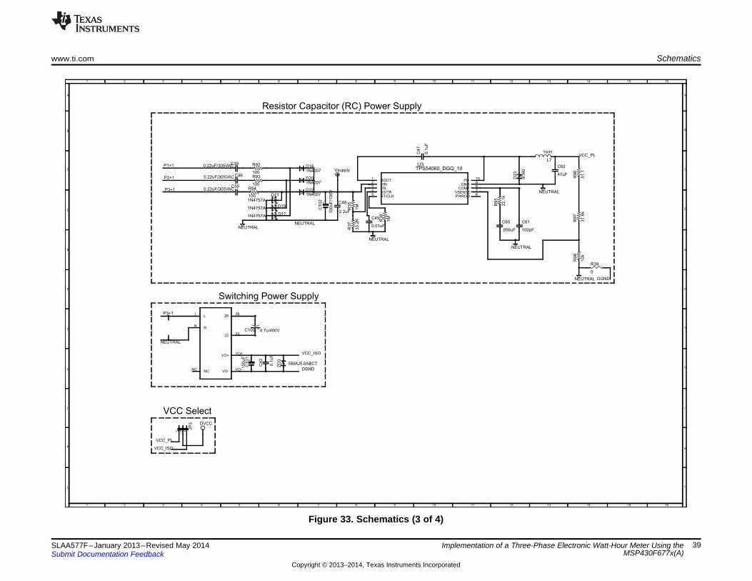
DVCC
2.2uF10
0u
F/1
00
V
0.22uF/305VAC
0.22uF/305VAC
Vsupply
1N4007
1N4007
1N4757A
1N4757A
0
0.22uF/305VAC1N4007
1N4757A
15
0u
F
0.1
uF
SMAJ5.0ABCT
4.7u/400V
TPS54060_DGQ_10
1M
33
.2K 1M
0.01uF
0.1
uF
100
100
100
22
.1k
.056uF 100pF
NEUTRAL
NEUTRAL
NEUTRAL
B1
60
1mH
47uF
NEUTRAL
51
.13
1.6
k1
0k
NEUTRAL
C48
C1
02
C46
C50
D20
D22D21
D19
R39
C39D18
D17
LL
NN
NCNC
26 26
22 22
VO+ VO+
VO- VO-
C1
01
C4
2
ZD
3
C100
123
JP
3
BOOT1
VIN2
EN3
SS/TR4
RT/CLK5 PWRGD 6VSENSE 7
COMP 8GND 9
PH 10
U3
R3
5R
37
R3
8
C45
C4
7
R92
R93
R94
R9
5
C60 C61
D2
3
L7
C62
R9
6R
97
R9
8
VCC_PL
VCC_PL
DGND
DGND
NEUTRAL
NEUTRAL
VCC_ISO
VCC_ISO
P1+1
P2+1
P3+1
P3+1
1 2 3 4 5 6 7 8 9 10 11 12 13 14 15 16
L
K
I
H
G
F
E
D
C
B
A
16151413121110987654321
A
B
C
D
E
F
G
H
I
K
L
+
+
VCC Select
Resistor Capacitor (RC) Power Supply
Switching Power Supply
www.ti.com Schematics
Figure 33. Schematics (3 of 4)
39SLAA577F–January 2013–Revised May 2014 Implementation of a Three-Phase Electronic Watt-Hour Meter Using theMSP430F677x(A)Submit Documentation Feedback
Copyright © 2013–2014, Texas Instruments Incorporated

RF Daughter Card
IR Pulse In/OutIsolated RS232 Communication
EZ-RF Connect
Act / React
EEPROM
DGND
DGND
DGND
PS8802
PS8802
SL127L6TH
1kTIL191
VCC
10
uF
0.1
uF
DGND
1kTIL191
VCC
DGND
DVCC
0000
00000000
0
00
DVCC
DVCC
47
DGND
0.1uF
4.7uF
DGND DGND
2.2k
68
DVCC
DNP
1.5k
1k
10
k
22
0
BC857BSMD
BC857BSMD
0.1
uF
LL103A
10uF
10uF
LL103A
LL103A
LL
10
3A
1k
2.2k
DN
P
0.1uF
DGNDDGND
24C02CSN
0.1
uF
DVCC
DGND
DGND
DGND
000
162738495
RS-232
G1
G2
2
3
78
5
6
U1
2
3
78
5
6
U2
1
RX
_E
N
21
TX
_E
N
2
1 23 45 67 89 10
11 1213 1415 1617 1819 20
RF2RF2
1 23 45 67 89 10
11 1213 1415 1617 1819 20
RF1RF1
EZ-RF
21
43
56
R68
1
2 3
4OPTO1
C5
8
C5
9
1JP11
2
R72
1
2 3
4OPTO2
1JP12
2
R74R76R80R82
R75R81R83R84R85R86R88R91
R87
R90R89
VCC2TXDRXDSDVCC1GND
R4
7
C52
C51
R69
R65R66
R67
R62
R6
3
R6
4Q2
Q1
C5
4
D24
C56
C55
D26
D25
D2
7R
78
R71
R7
0
C57
84
SCL6
SDA 5
A01A12A23
WP7VCC
GND
IC1
C4
1
R79R77R73
1
ACT
2
1
REACT
2
RF_FIFORF_FIFO
RF_FIFOPRF_FIFOP
RF_SFDRF_CCA
RF_SOMIRF_SIMORF_CLKRF_CS
UART_TX
DVCC
DVCC
DVCC
DGND
RF_GPIO2
ACTIR_SD
IR_RXDIR_TXD
REACT
DB9_-12V
DB9_GND
DB9_+12V
UART_RXRS232_RXD
RS232_TXD
EZ-RF_TXD
EZ-RF_RXD
SCL
SDA
RF_RESETCC
RF_RESETCC
RF_VREG_EN
RF_GPIO1
1 2 3 4 5 6 7 8 9 10 11 12 13 14 15 16
L
K
I
H
G
F
E
D
C
B
A
16151413121110987654321
A
B
C
D
E
F
G
H
I
K
L
IRDA
Arr
ay
EE
PR
OM
Schematics www.ti.com
Figure 34. Schematics (4 of 4)
40 Implementation of a Three-Phase Electronic Watt-Hour Meter Using the SLAA577F–January 2013–Revised May 2014MSP430F677x(A) Submit Documentation Feedback
Copyright © 2013–2014, Texas Instruments Incorporated
www.ti.com Revision History
Revision History
Changes from E Revision (January 2014) to F Revision ............................................................................................... Page
• Changed all references to the MSP430F677x devices to MSP430F677x(A) ..................................................... 1• Updated the associated software zip file............................................................................................... 1• Added link to other design documents ................................................................................................. 1• Changed Figure 2 ......................................................................................................................... 4• Changed paragraph that starts "To get an exact 90° phase shift..." .............................................................. 10• Changed file name of emeter-3ph-neutral-6779.h to emeter-3ph-neutral-6779(A).h ........................................... 15• Changed Figure 13 ...................................................................................................................... 19• Changed "Header", "Main Functionality", and "Comments" columns for DVCC VCC_ISO.................................... 23• Changed the "Comments" for DVCC VCC_PL ...................................................................................... 23• Added paragraph that starts "In this software package..." ......................................................................... 25• Changed all schematics in Section 7 ................................................................................................. 37
NOTE: Page numbers for previous revisions may differ from page numbers in the current version.
41SLAA577F–January 2013–Revised May 2014 Revision HistorySubmit Documentation Feedback
Copyright © 2013–2014, Texas Instruments Incorporated

WARNING
General Texas Instruments High Voltage Evaluation (TI HV EVM) User Safety Guidelines
Always follow TI's setup and application instructions, including use of all interface components within theirrecommended electrical rated voltage and power limits. Always use electrical safety precautions to helpensure your personal safety and those working around you. Contact TI's Product Information Centerhttp://support/ti./com for further information.
Save all warnings and instructions for future reference.Failure to follow warnings and instructions may result in personal injury, property damage, ordeath due to electrical shock and burn hazards.The term TI HV EVM refers to an electronic device typically provided as an open-framed unenclosedprinted circuit board assembly. It is intended strictly for use in development laboratory environments,solely for qualified professional users having training, expertise, and knowledge of electricalsafety risks in development and application of high voltage electrical circuits. Any other useand/or application are strictly prohibited by Texas Instruments. If you are not suitably qualified, youshould immediately stop from further use of the HV EVM.1. Work Area Safety
(a) Keep work area clean and orderly.(b) Qualified observer(s) must be present anytime circuits are energized.(c) Effective barriers and signage must be present in the area where the TI HV EVM and its interface
electronics are energized, indicating operation of accessible high voltages may be present, for thepurpose of protecting inadvertent access.
(d) All interface circuits, power supplies, evaluation modules, instruments, meters, scopes and otherrelated apparatus used in a development environment exceeding 50Vrms/75VDC must beelectrically located within a protected Emergency Power Off EPO protected power strip.
(e) Use stable and nonconductive work surface.(f) Use adequately insulated clamps and wires to attach measurement probes and instruments. No
freehand testing whenever possible.2. Electrical Safety
As a precautionary measure, it is always a good engineering practice to assume that the entire EVMmay have fully accessible and active high voltages.(a) De-energize the TI HV EVM and all its inputs, outputs and electrical loads before performing any
electrical or other diagnostic measurements. Revalidate that TI HV EVM power has been safely de-energized.
(b) With the EVM confirmed de-energized, proceed with required electrical circuit configurations,wiring, measurement equipment connection, and other application needs, while still assuming theEVM circuit and measuring instruments are electrically live.
(c) After EVM readiness is complete, energize the EVM as intended.WARNING: WHILE THE EVM IS ENERGIZED, NEVER TOUCH THE EVM OR ITS ELECTRICALCIRCUITS AS THEY COULD BE AT HIGH VOLTAGES CAPABLE OF CAUSING ELECTRICALSHOCK HAZARD.
3. Personal Safety(a) Wear personal protective equipment (for example, latex gloves or safety glasses with side shields)
or protect the EVM in an adequate lucent plastic box with interlocks to protect from accidentaltouch.
Limitation for safe use:EVMs are not to be used as all or part of a production unit.

ADDITIONAL TERMS AND CONDITIONS, WARNINGS, RESTRICTIONS, AND DISCLAIMERS FOREVALUATION MODULES
Texas Instruments Incorporated (TI) markets, sells, and loans all evaluation boards, kits, and/or modules (EVMs) pursuant to, and userexpressly acknowledges, represents, and agrees, and takes sole responsibility and risk with respect to, the following:
1. User agrees and acknowledges that EVMs are intended to be handled and used for feasibility evaluation only in laboratory and/ordevelopment environments. Notwithstanding the foregoing, in certain instances, TI makes certain EVMs available to users that do nothandle and use EVMs solely for feasibility evaluation only in laboratory and/or development environments, but may use EVMs in ahobbyist environment. All EVMs made available to hobbyist users are FCC certified, as applicable. Hobbyist users acknowledge, agree,and shall comply with all applicable terms, conditions, warnings, and restrictions in this document and are subject to the disclaimer andindemnity provisions included in this document.
2. Unless otherwise indicated, EVMs are not finished products and not intended for consumer use. EVMs are intended solely for use bytechnically qualified electronics experts who are familiar with the dangers and application risks associated with handling electricalmechanical components, systems, and subsystems.
3. User agrees that EVMs shall not be used as, or incorporated into, all or any part of a finished product.4. User agrees and acknowledges that certain EVMs may not be designed or manufactured by TI.5. User must read the user's guide and all other documentation accompanying EVMs, including without limitation any warning or
restriction notices, prior to handling and/or using EVMs. Such notices contain important safety information related to, for example,temperatures and voltages. For additional information on TI's environmental and/or safety programs, please visit www.ti.com/esh orcontact TI.
6. User assumes all responsibility, obligation, and any corresponding liability for proper and safe handling and use of EVMs.7. Should any EVM not meet the specifications indicated in the user’s guide or other documentation accompanying such EVM, the EVM
may be returned to TI within 30 days from the date of delivery for a full refund. THE FOREGOING LIMITED WARRANTY IS THEEXCLUSIVE WARRANTY MADE BY TI TO USER AND IS IN LIEU OF ALL OTHER WARRANTIES, EXPRESSED, IMPLIED, ORSTATUTORY, INCLUDING ANY WARRANTY OF MERCHANTABILITY OR FITNESS FOR ANY PARTICULAR PURPOSE. TI SHALLNOT BE LIABLE TO USER FOR ANY INDIRECT, SPECIAL, INCIDENTAL, OR CONSEQUENTIAL DAMAGES RELATED TO THEHANDLING OR USE OF ANY EVM.
8. No license is granted under any patent right or other intellectual property right of TI covering or relating to any machine, process, orcombination in which EVMs might be or are used. TI currently deals with a variety of customers, and therefore TI’s arrangement withthe user is not exclusive. TI assumes no liability for applications assistance, customer product design, software performance, orinfringement of patents or services with respect to the handling or use of EVMs.
9. User assumes sole responsibility to determine whether EVMs may be subject to any applicable federal, state, or local laws andregulatory requirements (including but not limited to U.S. Food and Drug Administration regulations, if applicable) related to its handlingand use of EVMs and, if applicable, compliance in all respects with such laws and regulations.
10. User has sole responsibility to ensure the safety of any activities to be conducted by it and its employees, affiliates, contractors ordesignees, with respect to handling and using EVMs. Further, user is responsible to ensure that any interfaces (electronic and/ormechanical) between EVMs and any human body are designed with suitable isolation and means to safely limit accessible leakagecurrents to minimize the risk of electrical shock hazard.
11. User shall employ reasonable safeguards to ensure that user’s use of EVMs will not result in any property damage, injury or death,even if EVMs should fail to perform as described or expected.
12. User shall be solely responsible for proper disposal and recycling of EVMs consistent with all applicable federal, state, and localrequirements.
Certain Instructions. User shall operate EVMs within TI’s recommended specifications and environmental considerations per the user’sguide, accompanying documentation, and any other applicable requirements. Exceeding the specified ratings (including but not limited toinput and output voltage, current, power, and environmental ranges) for EVMs may cause property damage, personal injury or death. Ifthere are questions concerning these ratings, user should contact a TI field representative prior to connecting interface electronics includinginput power and intended loads. Any loads applied outside of the specified output range may result in unintended and/or inaccurateoperation and/or possible permanent damage to the EVM and/or interface electronics. Please consult the applicable EVM user's guide priorto connecting any load to the EVM output. If there is uncertainty as to the load specification, please contact a TI field representative. Duringnormal operation, some circuit components may have case temperatures greater than 60°C as long as the input and output are maintainedat a normal ambient operating temperature. These components include but are not limited to linear regulators, switching transistors, passtransistors, and current sense resistors which can be identified using EVMs’ schematics located in the applicable EVM user's guide. Whenplacing measurement probes near EVMs during normal operation, please be aware that EVMs may become very warm. As with allelectronic evaluation tools, only qualified personnel knowledgeable in electronic measurement and diagnostics normally found indevelopment environments should use EVMs.Agreement to Defend, Indemnify and Hold Harmless. User agrees to defend, indemnify, and hold TI, its directors, officers, employees,agents, representatives, affiliates, licensors and their representatives harmless from and against any and all claims, damages, losses,expenses, costs and liabilities (collectively, "Claims") arising out of, or in connection with, any handling and/or use of EVMs. User’sindemnity shall apply whether Claims arise under law of tort or contract or any other legal theory, and even if EVMs fail to perform asdescribed or expected.Safety-Critical or Life-Critical Applications. If user intends to use EVMs in evaluations of safety critical applications (such as life support),and a failure of a TI product considered for purchase by user for use in user’s product would reasonably be expected to cause severepersonal injury or death such as devices which are classified as FDA Class III or similar classification, then user must specifically notify TIof such intent and enter into a separate Assurance and Indemnity Agreement.

RADIO FREQUENCY REGULATORY COMPLIANCE INFORMATION FOR EVALUATION MODULESTexas Instruments Incorporated (TI) evaluation boards, kits, and/or modules (EVMs) and/or accompanying hardware that is marketed, sold,or loaned to users may or may not be subject to radio frequency regulations in specific countries.General Statement for EVMs Not Including a RadioFor EVMs not including a radio and not subject to the U.S. Federal Communications Commission (FCC) or Industry Canada (IC)regulations, TI intends EVMs to be used only for engineering development, demonstration, or evaluation purposes. EVMs are not finishedproducts typically fit for general consumer use. EVMs may nonetheless generate, use, or radiate radio frequency energy, but have not beentested for compliance with the limits of computing devices pursuant to part 15 of FCC or the ICES-003 rules. Operation of such EVMs maycause interference with radio communications, in which case the user at his own expense will be required to take whatever measures maybe required to correct this interference.General Statement for EVMs including a radioUser Power/Frequency Use Obligations: For EVMs including a radio, the radio included in such EVMs is intended for development and/orprofessional use only in legally allocated frequency and power limits. Any use of radio frequencies and/or power availability in such EVMsand their development application(s) must comply with local laws governing radio spectrum allocation and power limits for such EVMs. It isthe user’s sole responsibility to only operate this radio in legally acceptable frequency space and within legally mandated power limitations.Any exceptions to this are strictly prohibited and unauthorized by TI unless user has obtained appropriate experimental and/or developmentlicenses from local regulatory authorities, which is the sole responsibility of the user, including its acceptable authorization.
U.S. Federal Communications Commission Compliance
For EVMs Annotated as FCC – FEDERAL COMMUNICATIONS COMMISSION Part 15 Compliant
CautionThis device complies with part 15 of the FCC Rules. Operation is subject to the following two conditions: (1) This device may not causeharmful interference, and (2) this device must accept any interference received, including interference that may cause undesired operation.Changes or modifications could void the user's authority to operate the equipment.
FCC Interference Statement for Class A EVM devicesThis equipment has been tested and found to comply with the limits for a Class A digital device, pursuant to part 15 of the FCC Rules.These limits are designed to provide reasonable protection against harmful interference when the equipment is operated in a commercialenvironment. This equipment generates, uses, and can radiate radio frequency energy and, if not installed and used in accordance with theinstruction manual, may cause harmful interference to radio communications. Operation of this equipment in a residential area is likely tocause harmful interference in which case the user will be required to correct the interference at its own expense.
FCC Interference Statement for Class B EVM devicesThis equipment has been tested and found to comply with the limits for a Class B digital device, pursuant to part 15 of the FCC Rules.These limits are designed to provide reasonable protection against harmful interference in a residential installation. This equipmentgenerates, uses and can radiate radio frequency energy and, if not installed and used in accordance with the instructions, may causeharmful interference to radio communications. However, there is no guarantee that interference will not occur in a particular installation. Ifthis equipment does cause harmful interference to radio or television reception, which can be determined by turning the equipment off andon, the user is encouraged to try to correct the interference by one or more of the following measures:
• Reorient or relocate the receiving antenna.• Increase the separation between the equipment and receiver.• Connect the equipment into an outlet on a circuit different from that to which the receiver is connected.• Consult the dealer or an experienced radio/TV technician for help.
Industry Canada Compliance (English)For EVMs Annotated as IC – INDUSTRY CANADA Compliant:
This Class A or B digital apparatus complies with Canadian ICES-003.Changes or modifications not expressly approved by the party responsible for compliance could void the user’s authority to operate theequipment.
Concerning EVMs Including Radio TransmittersThis device complies with Industry Canada licence-exempt RSS standard(s). Operation is subject to the following two conditions: (1) thisdevice may not cause interference, and (2) this device must accept any interference, including interference that may cause undesiredoperation of the device.
Concerning EVMs Including Detachable AntennasUnder Industry Canada regulations, this radio transmitter may only operate using an antenna of a type and maximum (or lesser) gainapproved for the transmitter by Industry Canada. To reduce potential radio interference to other users, the antenna type and its gain shouldbe so chosen that the equivalent isotropically radiated power (e.i.r.p.) is not more than that necessary for successful communication.This radio transmitter has been approved by Industry Canada to operate with the antenna types listed in the user guide with the maximumpermissible gain and required antenna impedance for each antenna type indicated. Antenna types not included in this list, having a gaingreater than the maximum gain indicated for that type, are strictly prohibited for use with this device.

Canada Industry Canada Compliance (French)
Cet appareil numérique de la classe A ou B est conforme à la norme NMB-003 du Canada
Les changements ou les modifications pas expressément approuvés par la partie responsable de la conformité ont pu vider l’autorité del'utilisateur pour actionner l'équipement.
Concernant les EVMs avec appareils radio
Le présent appareil est conforme aux CNR d'Industrie Canada applicables aux appareils radio exempts de licence. L'exploitation estautorisée aux deux conditions suivantes : (1) l'appareil ne doit pas produire de brouillage, et (2) l'utilisateur de l'appareil doit accepter toutbrouillage radioélectrique subi, même si le brouillage est susceptible d'en compromettre le fonctionnement.
Concernant les EVMs avec antennes détachables
Conformément à la réglementation d'Industrie Canada, le présent émetteur radio peut fonctionner avec une antenne d'un type et d'un gainmaximal (ou inférieur) approuvé pour l'émetteur par Industrie Canada. Dans le but de réduire les risques de brouillage radioélectrique àl'intention des autres utilisateurs, il faut choisir le type d'antenne et son gain de sorte que la puissance isotrope rayonnée équivalente(p.i.r.e.) ne dépasse pas l'intensité nécessaire à l'établissement d'une communication satisfaisante.
Le présent émetteur radio a été approuvé par Industrie Canada pour fonctionner avec les types d'antenne énumérés dans le manueld’usage et ayant un gain admissible maximal et l'impédance requise pour chaque type d'antenne. Les types d'antenne non inclus danscette liste, ou dont le gain est supérieur au gain maximal indiqué, sont strictement interdits pour l'exploitation de l'émetteur.
Mailing Address: Texas Instruments, Post Office Box 655303, Dallas, Texas 75265Copyright © 2014, Texas Instruments Incorporated
spacer
Important Notice for Users of EVMs Considered “Radio Frequency Products” in JapanEVMs entering Japan are NOT certified by TI as conforming to Technical Regulations of Radio Law of Japan.
If user uses EVMs in Japan, user is required by Radio Law of Japan to follow the instructions below with respect to EVMs:1. Use EVMs in a shielded room or any other test facility as defined in the notification #173 issued by Ministry of Internal Affairs and
Communications on March 28, 2006, based on Sub-section 1.1 of Article 6 of the Ministry’s Rule for Enforcement of Radio Law ofJapan,
2. Use EVMs only after user obtains the license of Test Radio Station as provided in Radio Law of Japan with respect to EVMs, or3. Use of EVMs only after user obtains the Technical Regulations Conformity Certification as provided in Radio Law of Japan with respect
to EVMs. Also, do not transfer EVMs, unless user gives the same notice above to the transferee. Please note that if user does notfollow the instructions above, user will be subject to penalties of Radio Law of Japan.
http://www.tij.co.jp
【無線電波を送信する製品の開発キットをお使いになる際の注意事項】 本開発キットは技術基準適合証明を受けておりません。 本製品のご使用に際しては、電波法遵守のため、以下のいずれかの措置を取っていただく必要がありますのでご注意ください。
1. 電波法施行規則第6条第1項第1号に基づく平成18年3月28日総務省告示第173号で定められた電波暗室等の試験設備でご使用いただく。2. 実験局の免許を取得後ご使用いただく。3. 技術基準適合証明を取得後ご使用いただく。。
なお、本製品は、上記の「ご使用にあたっての注意」を譲渡先、移転先に通知しない限り、譲渡、移転できないものとします
上記を遵守頂けない場合は、電波法の罰則が適用される可能性があることをご留意ください。
日本テキサス・インスツルメンツ株式会社東京都新宿区西新宿6丁目24番1号西新宿三井ビルhttp://www.tij.co.jp
Texas Instruments Japan Limited(address) 24-1, Nishi-Shinjuku 6 chome, Shinjuku-ku, Tokyo, Japan

IMPORTANT NOTICETexas Instruments Incorporated and its subsidiaries (TI) reserve the right to make corrections, enhancements, improvements and otherchanges to its semiconductor products and services per JESD46, latest issue, and to discontinue any product or service per JESD48, latestissue. Buyers should obtain the latest relevant information before placing orders and should verify that such information is current andcomplete. All semiconductor products (also referred to herein as “components”) are sold subject to TI’s terms and conditions of salesupplied at the time of order acknowledgment.TI warrants performance of its components to the specifications applicable at the time of sale, in accordance with the warranty in TI’s termsand conditions of sale of semiconductor products. Testing and other quality control techniques are used to the extent TI deems necessaryto support this warranty. Except where mandated by applicable law, testing of all parameters of each component is not necessarilyperformed.TI assumes no liability for applications assistance or the design of Buyers’ products. Buyers are responsible for their products andapplications using TI components. To minimize the risks associated with Buyers’ products and applications, Buyers should provideadequate design and operating safeguards.TI does not warrant or represent that any license, either express or implied, is granted under any patent right, copyright, mask work right, orother intellectual property right relating to any combination, machine, or process in which TI components or services are used. Informationpublished by TI regarding third-party products or services does not constitute a license to use such products or services or a warranty orendorsement thereof. Use of such information may require a license from a third party under the patents or other intellectual property of thethird party, or a license from TI under the patents or other intellectual property of TI.Reproduction of significant portions of TI information in TI data books or data sheets is permissible only if reproduction is without alterationand is accompanied by all associated warranties, conditions, limitations, and notices. TI is not responsible or liable for such altereddocumentation. Information of third parties may be subject to additional restrictions.Resale of TI components or services with statements different from or beyond the parameters stated by TI for that component or servicevoids all express and any implied warranties for the associated TI component or service and is an unfair and deceptive business practice.TI is not responsible or liable for any such statements.Buyer acknowledges and agrees that it is solely responsible for compliance with all legal, regulatory and safety-related requirementsconcerning its products, and any use of TI components in its applications, notwithstanding any applications-related information or supportthat may be provided by TI. Buyer represents and agrees that it has all the necessary expertise to create and implement safeguards whichanticipate dangerous consequences of failures, monitor failures and their consequences, lessen the likelihood of failures that might causeharm and take appropriate remedial actions. Buyer will fully indemnify TI and its representatives against any damages arising out of the useof any TI components in safety-critical applications.In some cases, TI components may be promoted specifically to facilitate safety-related applications. With such components, TI’s goal is tohelp enable customers to design and create their own end-product solutions that meet applicable functional safety standards andrequirements. Nonetheless, such components are subject to these terms.No TI components are authorized for use in FDA Class III (or similar life-critical medical equipment) unless authorized officers of the partieshave executed a special agreement specifically governing such use.Only those TI components which TI has specifically designated as military grade or “enhanced plastic” are designed and intended for use inmilitary/aerospace applications or environments. Buyer acknowledges and agrees that any military or aerospace use of TI componentswhich have not been so designated is solely at the Buyer's risk, and that Buyer is solely responsible for compliance with all legal andregulatory requirements in connection with such use.TI has specifically designated certain components as meeting ISO/TS16949 requirements, mainly for automotive use. In any case of use ofnon-designated products, TI will not be responsible for any failure to meet ISO/TS16949.Products ApplicationsAudio www.ti.com/audio Automotive and Transportation www.ti.com/automotiveAmplifiers amplifier.ti.com Communications and Telecom www.ti.com/communicationsData Converters dataconverter.ti.com Computers and Peripherals www.ti.com/computersDLP® Products www.dlp.com Consumer Electronics www.ti.com/consumer-appsDSP dsp.ti.com Energy and Lighting www.ti.com/energyClocks and Timers www.ti.com/clocks Industrial www.ti.com/industrialInterface interface.ti.com Medical www.ti.com/medicalLogic logic.ti.com Security www.ti.com/securityPower Mgmt power.ti.com Space, Avionics and Defense www.ti.com/space-avionics-defenseMicrocontrollers microcontroller.ti.com Video and Imaging www.ti.com/videoRFID www.ti-rfid.comOMAP Applications Processors www.ti.com/omap TI E2E Community e2e.ti.comWireless Connectivity www.ti.com/wirelessconnectivity
Mailing Address: Texas Instruments, Post Office Box 655303, Dallas, Texas 75265Copyright © 2014, Texas Instruments Incorporated

Mouser Electronics
Authorized Distributor
Click to View Pricing, Inventory, Delivery & Lifecycle Information: Texas Instruments:
EVM430-F6779
![User Manual Three Phase Energy Meter - INOGATE Manual Three Phase Energy Meter HXE310 CT & CTPT Meter Hexing Electrical Co., Ltd. [2013.3] Meter User Manual-HXE310 2 / 76 Introduction](https://img.pdfslide.net/doc/110x75/5aa750e17f8b9a50528c3353/user-manual-three-phase-energy-meter-manual-three-phase-energy-meter-hxe310-ct.jpg)


![Installation Manual Three Phase Energy Meter - INOGATE … · Installation Manual Three Phase Energy Meter For HXE310 CT & CTPT Meter Hexing Electrical Co., Ltd. [2013.3]](https://img.pdfslide.net/doc/110x75/5a71ede67f8b9a98538d4853/installation-manual-three-phase-energy-meter-inogatewwwinogateorginstallationmanualofhxe310ctctptmeter.jpg)