Embed Size (px)
Citation preview
www.theinternationaljournal.org > RJSITM: Volume: 03, Number: 02, December-2013 Page 22
Implementation of Artificial Neural Network Technique for Power Quality
Conditioning System by UPQC
Dr. K.S. Srikanth, Professor,
Electrical and Electronics Department, KL University, Andhra Pradesh, India
Abstract:- This paper presents a new unified power-quality conditioning system (MC-UPQC),
capable of simultaneous compensation for voltage and current in multibus/multifeeder systems. In this
configuration, one shunt voltage-source converter (shunt VSC) and two or more series VSCs exist. The
system can be applied to adjacent feeders to compensate for supply-voltage and load current
imperfections on the main feeder and full compensation of supply voltage imperfections on the other
feeders. In the proposed configuration, all converters are connected back to back on the dc side and
share a common dc-link capacitor. Therefore, power can be transferred from one feeder to adjacent
feeders to compensate for sag/swell and interruption. The performance of the MC-UPQC as well as the
adopted control algorithm is illustrated by simulation. The present work study the compensation
principle and different control strategies used here are based on PI & ANN Controller of the MC-
UPQC in detail. The results obtained in MATLAB/PSCAD on a two-bus/two-feeder system show the
effectiveness of the proposed configuration.
Index Terms- power quality (PQ) unified power-quality conditioner (UPQC), voltage-source converter
(VSC), Artificial neural network- ANN.
I. INTRODUCTION
With increasing applications of nonlinear and electronically switched devices in distribution
systems and industries, power-quality (PQ) problems, such as harmonics, flicker, and imbalance have
become serious concerns. In addition, lightning strikes on transmission lines, switching of capacitor
banks, and various network faults can also cause PQ problems, such as transients, voltage sag/swell,
and interruption. On the other hand, an increase of sensitive loads involving digital electronics and
complex process controllers requires a pure sinusoidal supply voltage for proper load operation [1]. In
order to meet PQ standard limits, it may be necessary to include some sort of compensation. Modern
solutions can be found in the form of active rectification on a active filtering [2]. A shunt active power
filter is suitable for the suppression of negative load influence on the supply network, but if there are
supply voltage imperfections, a series active power filter may be needed to provide full compensation
[3].
In recent years, solutions based on flexible ac transmission systems (FACTS) have appeared. The
application of FACTS concepts in distribution systems has resulted in a new generation of
compensating devices. A unified power-quality conditioner (UPQC) [4] is the extension of the unified
power-flow controller (UPFC) [5] concept at the distribution level. It consists of combined series and
shunt converters for simultaneous compensation of voltage and current imperfections in a supply
Feeder [6]-[8]. Recently, multiconverter (FACTS) devices, such as interline power-flow controller
(IPFC) [9] and the generalized unified power-flow controller (GUPFC) [10] are introduced. The aim of
these devices is to control the power flow of multilines or a sub network rather than control the power
flow of a single line by, for instance, a UPFC. When the power flows of two lines starting in one
substation need to be controlled, an interline power flow controller (IPFC) can be used. An IPFC
consists of two series VSCs whose dc capacitors are coupled. This allows active power to circulate
between the VSCs. With this configuration, two lines can be controlled simultaneously to optimize the
network utilization.
www.theinternationaljournal.org > RJSITM: Volume: 03, Number: 02, December-2013 Page 23
This concept can be extended to design multi-converter configurations for PQ improvement in
adjacent feeders. For example, the interline unified power-quality conditioner (IUPQC), which is the
extension of the IPFC concept at the distribution level, has been proposed in [11]. The IUPQC consists
of one series and one shunt converter. It is connected between two feeders to regulate the bus voltage
of one of the feeders, while regulating the voltage across a sensitive load in the other feeder. In this
configuration, the voltage regulation in one of the feeders is performed by the shunt-VSC. However,
since the source impedance is very low, a high amount of current would be needed to boost bus
voltage in case of a voltage sag/swell which is not feasible. It also has low dynamic performance
because the dc-link capacitor voltage is not regulated.
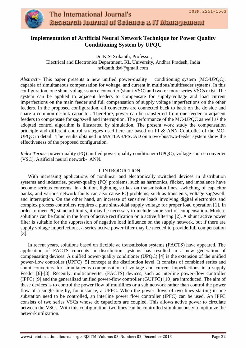
Fig.1.Block diagram of MC_UPQC with STATCOM
In this paper, a new configuration of a UPQC called the multiconverter unified power quality
conditioner (MC_UPQC) is presented. The system is extended by adding a series-VSC in an adjacent
feeder. The proposed topology can be used for Simultaneous compensation of voltage and current
imperfections both feeders by sharing power compensation capabilities between two adjacent feeders
which are not connected. The system is also capable of compensating for interruptions without the
need for a battery storage system and consequently without storage capacity limitations. The
performance of the MC-UPQC as well as the adopted control algorithm is illustrated by simulation.
The present work study the compensation principle and different control strategies used here are based
on PI & ANN Controller of the MC-UPQC in detail. The results obtained in MATLAB/PSCAD on a
two-bus/two-feeder system show the effectiveness of the proposed configuration.
II. PROPOSED MC-UPQC SYSTEM
A. Circuit configuration
The single-line diagram of a distribution system with an MC-UPQC is As shown in Fig. 1.In this
figure two feeders connected to two different substations supply the loads L1 and L2 With
STATCOM. The MC-UPQC is connected to two buses BUS1 and BUS2 with voltages of and ,
respectively. The shunt part of the MC-UPQC is also connected to load L1 with a current of . Supply
voltages are denoted by and while load voltages are denoted by and . Finally, feeder
currents are denoted by and and load currents are and .
Bus voltages and are distorted and may be subjected to sag/swell. The load L1 is a
nonlinear/sensitive load which needs a pure sinusoidal voltage for proper operation while its current is
no sinusoidal and contains harmonics. The load L2 is a sensitive/critical load which needs a purely
sinusoidal voltage and must be fully protected against distortion, sag/swell, and interruption. These
types of loads primarily include production industries and critical service providers, such as medical
centers, airports, or broadcasting centers where voltage interruption can result in service economical
losses or human damages.
www.theinternationaljournal.org > RJSITM: Volume: 03, Number: 02, December-2013 Page 24
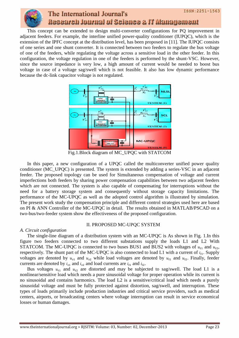
Fig.2 Typical Sim-link Block diagram MC-UPQC used in distribution system
B. MC-UPQC Structure
The internal structure of the MC-UPQC is shown in Fig. 2. It consists of three VSCs (VSC1,
VSC2, and VSC3) which are connected back to back through a common dc-link capacitor. In the
proposed configuration, VSC1 is connected in series with BUS1 and VSC2 is connected in parallel
with load L1 at the end of Feeder1. VSC3 is connected in series with BUS2 at the Feeder2 end Each of
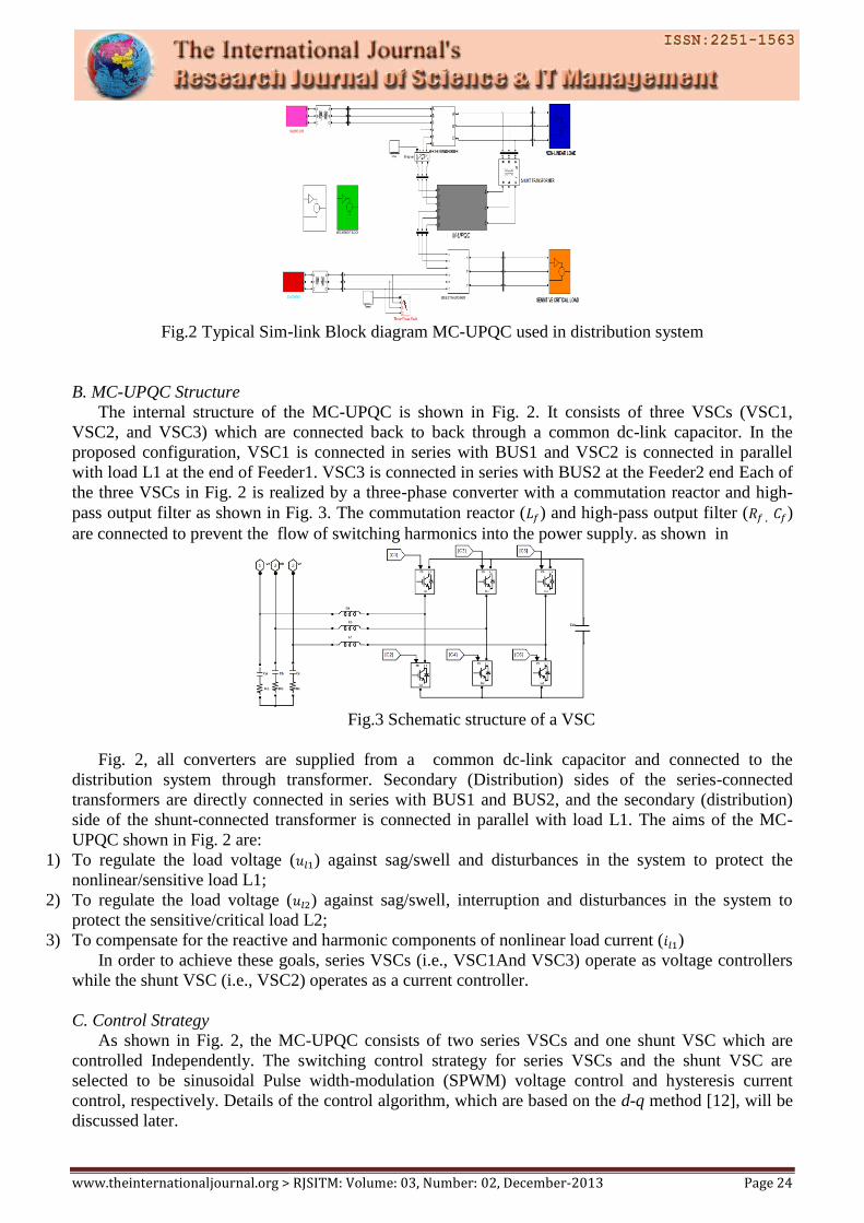
the three VSCs in Fig. 2 is realized by a three-phase converter with a commutation reactor and high-
pass output filter as shown in Fig. 3. The commutation reactor ( ) and high-pass output filter ( )
are connected to prevent the flow of switching harmonics into the power supply. as shown in
Fig.3 Schematic structure of a VSC
Fig. 2, all converters are supplied from a common dc-link capacitor and connected to the
distribution system through transformer. Secondary (Distribution) sides of the series-connected
transformers are directly connected in series with BUS1 and BUS2, and the secondary (distribution)
side of the shunt-connected transformer is connected in parallel with load L1. The aims of the MC-
UPQC shown in Fig. 2 are:
1) To regulate the load voltage ( ) against sag/swell and disturbances in the system to protect the
nonlinear/sensitive load L1;
2) To regulate the load voltage ( ) against sag/swell, interruption and disturbances in the system to
protect the sensitive/critical load L2;
3) To compensate for the reactive and harmonic components of nonlinear load current ( )
In order to achieve these goals, series VSCs (i.e., VSC1And VSC3) operate as voltage controllers
while the shunt VSC (i.e., VSC2) operates as a current controller.
C. Control Strategy
As shown in Fig. 2, the MC-UPQC consists of two series VSCs and one shunt VSC which are
controlled Independently. The switching control strategy for series VSCs and the shunt VSC are
selected to be sinusoidal Pulse width-modulation (SPWM) voltage control and hysteresis current
control, respectively. Details of the control algorithm, which are based on the d-q method [12], will be
discussed later.
www.theinternationaljournal.org > RJSITM: Volume: 03, Number: 02, December-2013 Page 25
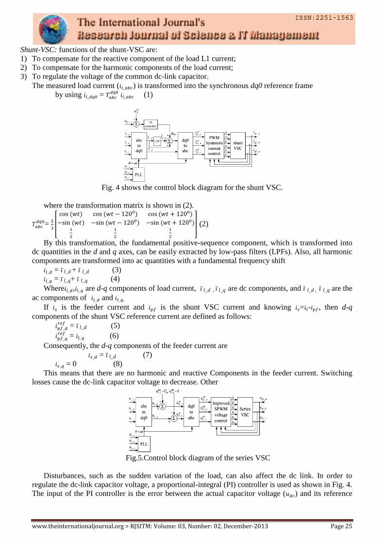
Shunt-VSC: functions of the shunt-VSC are:
1) To compensate for the reactive component of the load L1 current;
2) To compensate for the harmonic components of the load current;
3) To regulate the voltage of the common dc-link capacitor.
The measured load current ( ) is transformed into the synchronous dq0 reference frame
by using = (1)
Fig. 4 shows the control block diagram for the shunt VSC.
where the transformation matrix is shown in (2).
=
(2)
By this transformation, the fundamental positive-sequence component, which is transformed into
dc quantities in the d and q axes, can be easily extracted by low-pass filters (LPFs). Also, all harmonic
components are transformed into ac quantities with a fundamental frequency shift
= l_d + l_d (3)
= l_q+ l_q (4)
Where , are d-q components of load current, l_d , l_q are dc components, and l_d , l_q are the
ac components of and .
If is the feeder current and is the shunt VSC current and knowing = - , then d-q
components of the shunt VSC reference current are defined as follows:
= l_d (5)
= (6)
Consequently, the d-q components of the feeder current are
= l_d (7)
= 0 (8)
This means that there are no harmonic and reactive Components in the feeder current. Switching
losses cause the dc-link capacitor voltage to decrease. Other
Fig.5.Control block diagram of the series VSC
Disturbances, such as the sudden variation of the load, can also affect the dc link. In order to
regulate the dc-link capacitor voltage, a proportional-integral (PI) controller is used as shown in Fig. 4.
The input of the PI controller is the error between the actual capacitor voltage ( ) and its reference
www.theinternationaljournal.org > RJSITM: Volume: 03, Number: 02, December-2013 Page 26
value (
The output of the PI controller (i.e., ) is added to the d component of the shunt-VSC
reference current to form a new reference current as follows:
………..(9)
As shown in Fig. 4, the reference current in(9) is then transformed back into the abc reference
frame. By using PWM hysteresis current control, the output-compensating currents in each phase are
obtained
=
; (
= )…… (10)
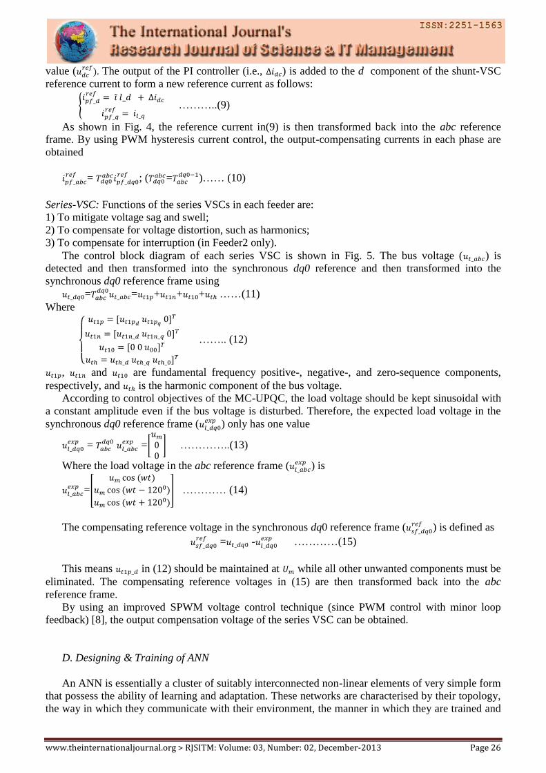
Series-VSC: Functions of the series VSCs in each feeder are:
1) To mitigate voltage sag and swell;
2) To compensate for voltage distortion, such as harmonics;
3) To compensate for interruption (in Feeder2 only).
The control block diagram of each series VSC is shown in Fig. 5. The bus voltage ( ) is
detected and then transformed into the synchronous dq0 reference and then transformed into the
synchronous dq0 reference frame using
=
= + + + ……(11)
Where
…….. (12)
, and are fundamental frequency positive-, negative-, and zero-sequence components,
respectively, and is the harmonic component of the bus voltage.
According to control objectives of the MC-UPQC, the load voltage should be kept sinusoidal with
a constant amplitude even if the bus voltage is disturbed. Therefore, the expected load voltage in the
synchronous dq0 reference frame ( ) only has one value
=
=
…………..(13)
Where the load voltage in the abc reference frame ( ) is
=
………… (14)
The compensating reference voltage in the synchronous dq0 reference frame ( ) is defined as
= -
…………(15)
This means in (12) should be maintained at while all other unwanted components must be
eliminated. The compensating reference voltages in (15) are then transformed back into the abc
reference frame.
By using an improved SPWM voltage control technique (since PWM control with minor loop
feedback) [8], the output compensation voltage of the series VSC can be obtained.
D. Designing & Training of ANN
An ANN is essentially a cluster of suitably interconnected non-linear elements of very simple form
that possess the ability of learning and adaptation. These networks are characterised by their topology,
the way in which they communicate with their environment, the manner in which they are trained and
www.theinternationaljournal.org > RJSITM: Volume: 03, Number: 02, December-2013 Page 27
their ability to process information [18]. Their ease of use, inherent reliability and fault tolerance has
made ANNs a viable medium for control.
An alternative to fuzzy controllers in many cases, neural controllers share the need to replace hard
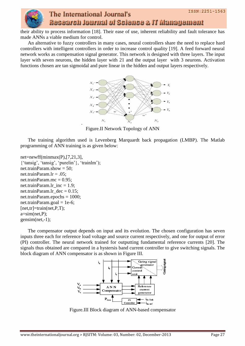
controllers with intelligent controllers in order to increase control quality [19]. A feed forward neural
network works as compensation signal generator. This network is designed with three layers. The input
layer with seven neurons, the hidden layer with 21 and the output layer with 3 neurons. Activation
functions chosen are tan sigmoidal and pure linear in the hidden and output layers respectively.
.
Figure.II Network Topology of ANN
The training algorithm used is Levenberg Marquardt back propagation (LMBP). The Matlab
programming of ANN training is as given below:
net=newff(minmax(P),[7,21,3],
‘tansig’, ‘tansig’, ‘purelin’, ‘trainlm’);
net.trainParam.show = 50;
net.trainParam.lr = .05;
net.trainParam.mc = 0.95;
net.trainParam.lr_inc = 1.9;
net.trainParam.lr_dec = 0.15;
net.trainParam.epochs = 1000;
net.trainParam.goal = 1e-6;
[net,tr]=train(net,P,T);
a=sim(net,P);
gensim(net,-1);
The compensator output depends on input and its evolution. The chosen configuration has seven
inputs three each for reference load voltage and source current respectively, and one for output of error
(PI) controller. The neural network trained for outputting fundamental reference currents [20]. The
signals thus obtained are compared in a hystersis band current controller to give switching signals. The
block diagram of ANN compensator is as shown in Figure III.
Figure.III Block diagram of ANN-based compensator
www.theinternationaljournal.org > RJSITM: Volume: 03, Number: 02, December-2013 Page 28
III. POWER-RATING ANALYSIS OF THE MC-UPQC
The power rating of the MC-UPQC is an important factor in terms of cost. Before calculation of
the power rating of each VSC in the MC-UPQC structure, two models of a UPQC are analyzed and the
best model which requires the minimum power rating is considered. All voltage and current phasors
used in this section are phase quantities at the fundamental frequency.
There are two models for a UPQC-quadrature compensate (UPQC-Q) and inphase
compensation (UPQC-P). In the quadrature compensation scheme, the injected voltage by the series-
VSC maintains a quadrature advance relationship with the supply current so that no real power is
consumed by the series VSC at steady state. This is a significant advantage when UPQC mitigates sag
condition. The series VSC also shares the volt-ampere reactive (VAR) of the load with the shunt-VSC,
reducing the power rating of the shunt-VSC.
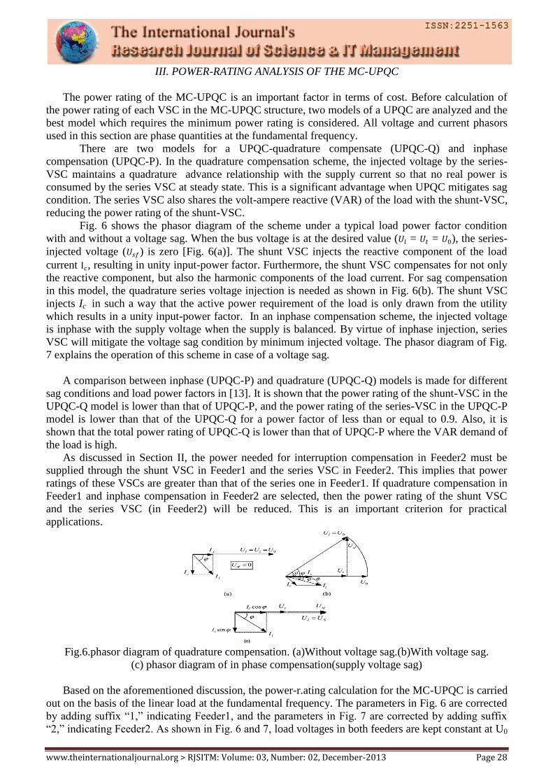
Fig. 6 shows the phasor diagram of the scheme under a typical load power factor condition
with and without a voltage sag. When the bus voltage is at the desired value ( = = ), the series-
injected voltage ( ) is zero [Fig. 6(a)]. The shunt VSC injects the reactive component of the load
current , resulting in unity input-power factor. Furthermore, the shunt VSC compensates for not only
the reactive component, but also the harmonic components of the load current. For sag compensation
in this model, the quadrature series voltage injection is needed as shown in Fig. 6(b). The shunt VSC
injects Ic in such a way that the active power requirement of the load is only drawn from the utility
which results in a unity input-power factor. In an inphase compensation scheme, the injected voltage
is inphase with the supply voltage when the supply is balanced. By virtue of inphase injection, series
VSC will mitigate the voltage sag condition by minimum injected voltage. The phasor diagram of Fig.
7 explains the operation of this scheme in case of a voltage sag.
A comparison between inphase (UPQC-P) and quadrature (UPQC-Q) models is made for different
sag conditions and load power factors in [13]. It is shown that the power rating of the shunt-VSC in the
UPQC-Q model is lower than that of UPQC-P, and the power rating of the series-VSC in the UPQC-P
model is lower than that of the UPQC-Q for a power factor of less than or equal to 0.9. Also, it is
shown that the total power rating of UPQC-Q is lower than that of UPQC-P where the VAR demand of
the load is high.
As discussed in Section II, the power needed for interruption compensation in Feeder2 must be
supplied through the shunt VSC in Feeder1 and the series VSC in Feeder2. This implies that power
ratings of these VSCs are greater than that of the series one in Feeder1. If quadrature compensation in
Feeder1 and inphase compensation in Feeder2 are selected, then the power rating of the shunt VSC
and the series VSC (in Feeder2) will be reduced. This is an important criterion for practical
applications.
Fig.6.phasor diagram of quadrature compensation. (a)Without voltage sag.(b)With voltage sag.
(c) phasor diagram of in phase compensation(supply voltage sag)
Based on the aforementioned discussion, the power-r.ating calculation for the MC-UPQC is carried
out on the basis of the linear load at the fundamental frequency. The parameters in Fig. 6 are corrected
by adding suffix “1,” indicating Feeder1, and the parameters in Fig. 7 are corrected by adding suffix
“2,” indicating Feeder2. As shown in Fig. 6 and 7, load voltages in both feeders are kept constant at U0
www.theinternationaljournal.org > RJSITM: Volume: 03, Number: 02, December-2013 Page 29
regardless of bus voltages variation, and the load currents in both feeders are assumed to be constant at
their rated values (i.e., I01 and I02, respectively)
= = …….. (16)
…….....(17)
The load power factors in Feeder1 and Feeder2 are assumed to be and and the per-unit
sags, which must be compensated in Feeder1 and Feeder2, are supposed to be and , respectively.
If the MC-UPQC is lossless, the active power demand supplied by Feeder1 consists of two parts:
1) The active power demand of load in Feeder1;
2) The active power demand for sag and interruption compensation in Feeder2.
Thus, Feeder1 current ( ) can be found as
……(18)
…(19)
(1- …….. (20)
…..(21)
From Fig. 6, the voltage injected by the series VSC in Feeder1 can be written as in (22) and, thus, the
power rating of this converter ( ) can be calculated as
………(22)
×
….(23)
The shunt VSC current is divided into two parts.
1) The first part (i.e., ) compensates for the reactive component (and harmonic
components) of Feeder1 current and can be calculated from Fig. 6 as
= ...(24)
Where is calculated in (21). This part of the shunt VSC current only exchanges reactive power (Q)
with the system.
2) The second part provides the real power (P), which is needed for a sag or
interruption compensation in Feeder2. Therefore, the power rating of the shunt VSC can be calculated
as =3
….(25)
where is calculated in (24).
Finally, the power rating of the series-VSC in Feeder2 can be calculated by (26). For the worst-
case scenario (i.e., interruption compensation), one must consider = 1. Therefore
………26)
IV. SIMULATION RESULTS
The proposed MC-UPQC and its ANN control schemes have been tested through extensive case
study simulations using MATLAB/PSCAD. In this section, simulation results are presented, and the
performance of the proposed MC-UPQC system is shown.
www.theinternationaljournal.org > RJSITM: Volume: 03, Number: 02, December-2013 Page 30
Fig 7 Artificial Neural Networks
A. Distortion and sag/swell on the Bus voltage
Let us consider that the power system in Fig. 2 consists of two three-phase three-wire 380(v) (rms,
L-L), 50-Hz utilities. The BUS1 voltage ( ) contains the seventh-order harmonic with a value of
22%, and the BUS2 voltage ( ) contains the fifth-order harmonic with a value of 35%. The BUS1
voltage contains 25% sag between 0.1 s < t < 0.2 s and 20% swell between 0.2 s < t < 0.3 s. The BUS2
voltage contains 35% sag between 0.15 s < t < 0.25 s and 30% swell between 0.25 s < t < 0.3 s. The
nonlinear/sensitive load L1 is a three-phase rectifier load which supplies an RC load of 10Ω and 30
µF. Finally, the critical load L2 contains a balance RL load of 10 Ω and 100mH.
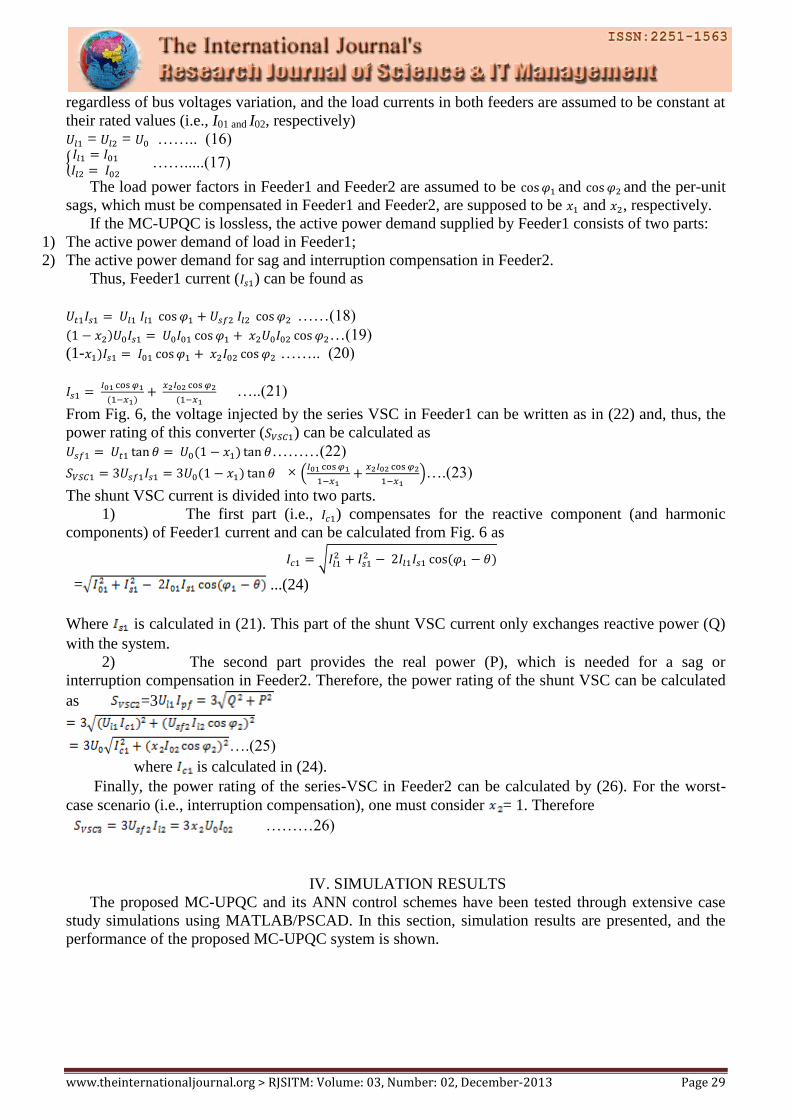
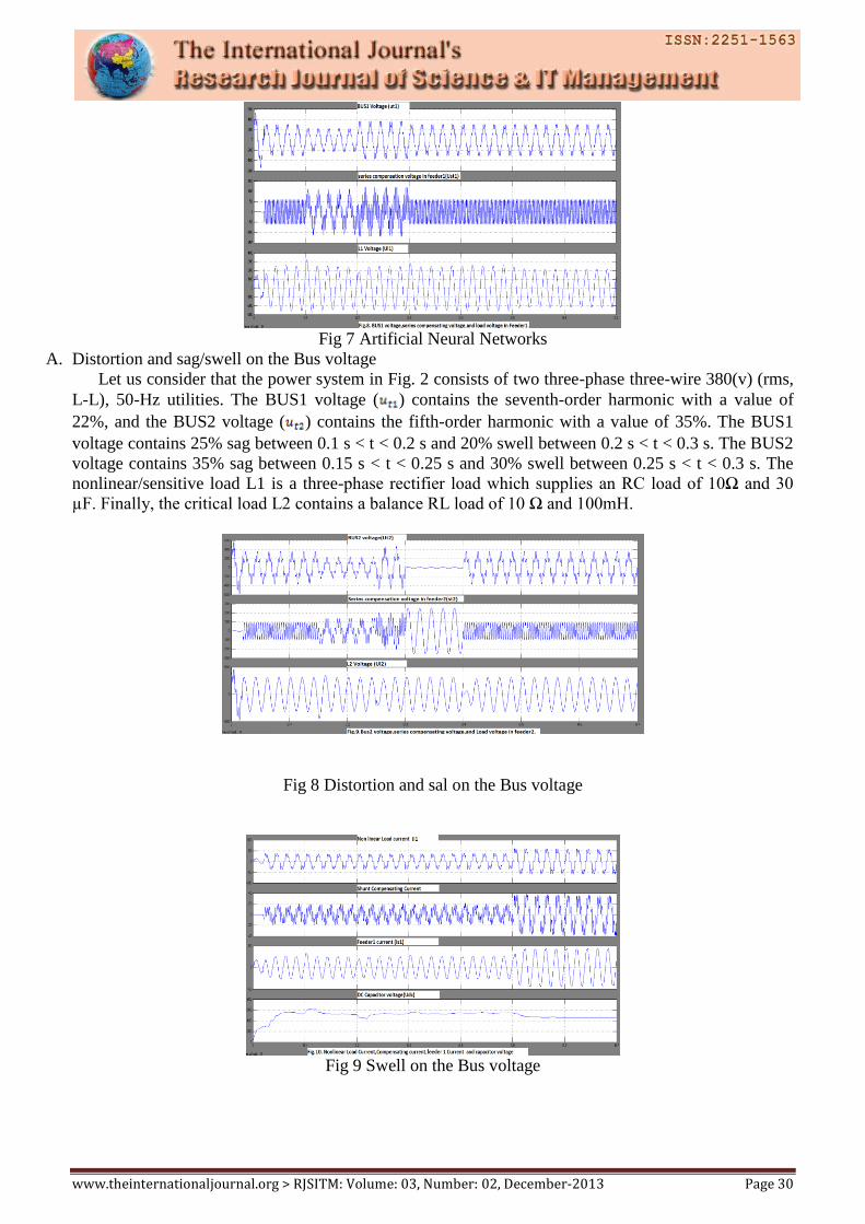
Fig 8 Distortion and sal on the Bus voltage
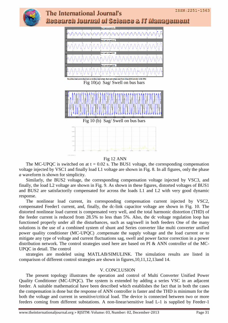
Fig 9 Swell on the Bus voltage
www.theinternationaljournal.org > RJSITM: Volume: 03, Number: 02, December-2013 Page 31
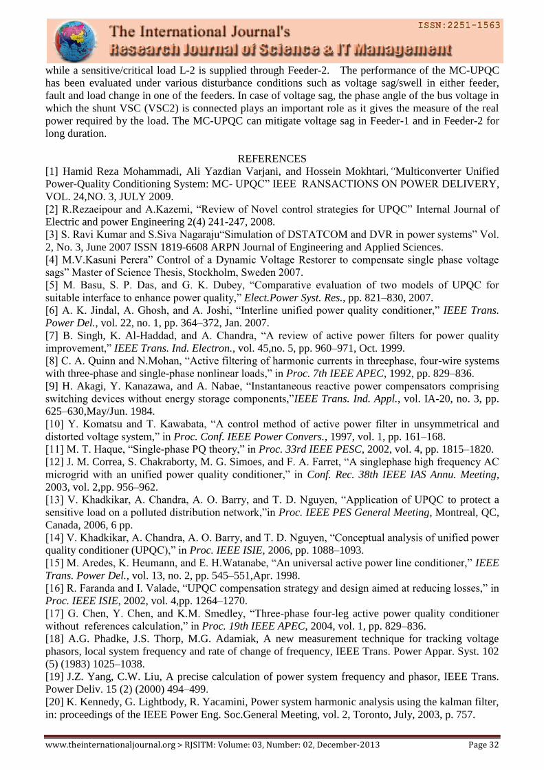
Fig 10(a) Sag/ Swell on bus bars
Fig 10 (b) Sag/ Swell on bus bars
Fig 12 ANN
The MC-UPQC is switched on at t = 0.02 s. The BUS1 voltage, the corresponding compensation
voltage injected by VSC1 and finally load L1 voltage are shown in Fig. 8. In all figures, only the phase
a waveform is shown for simplicity.
Similarly, the BUS2 voltage, the corresponding compensation voltage injected by VSC3, and
finally, the load L2 voltage are shown in Fig. 9. As shown in these figures, distorted voltages of BUS1
and BUS2 are satisfactorily compensated for across the loads L1 and L2 with very good dynamic
response.
The nonlinear load current, its corresponding compensation current injected by VSC2,
compensated Feeder1 current, and, finally, the dc-link capacitor voltage are shown in Fig. 10. The
distorted nonlinear load current is compensated very well, and the total harmonic distortion (THD) of
the feeder current is reduced from 28.5% to less than 5%. Also, the dc voltage regulation loop has
functioned properly under all the disturbances, such as sag/swell in both feeders One of the many
solutions is the use of a combined system of shunt and Series converter like multi converter unified
power quality conditioner (MC-UPQC) .compensate the supply voltage and the load current or to
mitigate any type of voltage and current fluctuations sag, swell and power factor correction in a power
distribution network. The control strategies used here are based on PI & ANN controller of the MC-
UPQC in detail. The control
strategies are modeled using MATLAB/SIMULINK. The simulation results are listed in
comparison of different control strategies are shown in figures,10,11,12,13and 14.
V. CONCLUSION
The present topology illustrates the operation and control of Multi Converter Unified Power
Quality Conditioner (MC-UPQC). The system is extended by adding a series VSC in an adjacent
feeder. A suitable mathematical have been described which establishes the fact that in both the cases
the compensation is done but the response of ANN controller is faster and the THD is minimum for the
both the voltage and current in sensitive/critical load. The device is connected between two or more
feeders coming from different substations. A non-linear/sensitive load L-1 is supplied by Feeder-1
www.theinternationaljournal.org > RJSITM: Volume: 03, Number: 02, December-2013 Page 32
while a sensitive/critical load L-2 is supplied through Feeder-2. The performance of the MC-UPQC
has been evaluated under various disturbance conditions such as voltage sag/swell in either feeder,
fault and load change in one of the feeders. In case of voltage sag, the phase angle of the bus voltage in
which the shunt VSC (VSC2) is connected plays an important role as it gives the measure of the real
power required by the load. The MC-UPQC can mitigate voltage sag in Feeder-1 and in Feeder-2 for
long duration.
REFERENCES
[1] Hamid Reza Mohammadi, Ali Yazdian Varjani, and Hossein Mokhtari,“Multiconverter Unified
Power-Quality Conditioning System: MC- UPQC” IEEE RANSACTIONS ON POWER DELIVERY,
VOL. 24,NO. 3, JULY 2009.
[2] R.Rezaeipour and A.Kazemi, “Review of Novel control strategies for UPQC” Internal Journal of
Electric and power Engineering 2(4) 241-247, 2008.
[3] S. Ravi Kumar and S.Siva Nagaraju“Simulation of DSTATCOM and DVR in power systems” Vol.
2, No. 3, June 2007 ISSN 1819-6608 ARPN Journal of Engineering and Applied Sciences.
[4] M.V.Kasuni Perera” Control of a Dynamic Voltage Restorer to compensate single phase voltage
sags” Master of Science Thesis, Stockholm, Sweden 2007.
[5] M. Basu, S. P. Das, and G. K. Dubey, “Comparative evaluation of two models of UPQC for
suitable interface to enhance power quality,” Elect.Power Syst. Res., pp. 821–830, 2007.
[6] A. K. Jindal, A. Ghosh, and A. Joshi, “Interline unified power quality conditioner,” IEEE Trans.
Power Del., vol. 22, no. 1, pp. 364–372, Jan. 2007.
[7] B. Singh, K. Al-Haddad, and A. Chandra, “A review of active power filters for power quality
improvement,” IEEE Trans. Ind. Electron., vol. 45,no. 5, pp. 960–971, Oct. 1999.
[8] C. A. Quinn and N.Mohan, “Active filtering of harmonic currents in threephase, four-wire systems
with three-phase and single-phase nonlinear loads,” in Proc. 7th IEEE APEC, 1992, pp. 829–836.
[9] H. Akagi, Y. Kanazawa, and A. Nabae, “Instantaneous reactive power compensators comprising
switching devices without energy storage components,”IEEE Trans. Ind. Appl., vol. IA-20, no. 3, pp.
625–630,May/Jun. 1984.
[10] Y. Komatsu and T. Kawabata, “A control method of active power filter in unsymmetrical and
distorted voltage system,” in Proc. Conf. IEEE Power Convers., 1997, vol. 1, pp. 161–168.
[11] M. T. Haque, “Single-phase PQ theory,” in Proc. 33rd IEEE PESC, 2002, vol. 4, pp. 1815–1820.
[12] J. M. Correa, S. Chakraborty, M. G. Simoes, and F. A. Farret, “A singlephase high frequency AC
microgrid with an unified power quality conditioner,” in Conf. Rec. 38th IEEE IAS Annu. Meeting,
2003, vol. 2,pp. 956–962.
[13] V. Khadkikar, A. Chandra, A. O. Barry, and T. D. Nguyen, “Application of UPQC to protect a
sensitive load on a polluted distribution network,”in Proc. IEEE PES General Meeting, Montreal, QC,
Canada, 2006, 6 pp.
[14] V. Khadkikar, A. Chandra, A. O. Barry, and T. D. Nguyen, “Conceptual analysis of unified power
quality conditioner (UPQC),” in Proc. IEEE ISIE, 2006, pp. 1088–1093.
[15] M. Aredes, K. Heumann, and E. H.Watanabe, “An universal active power line conditioner,” IEEE
Trans. Power Del., vol. 13, no. 2, pp. 545–551,Apr. 1998.
[16] R. Faranda and I. Valade, “UPQC compensation strategy and design aimed at reducing losses,” in
Proc. IEEE ISIE, 2002, vol. 4,pp. 1264–1270.
[17] G. Chen, Y. Chen, and K.M. Smedley, “Three-phase four-leg active power quality conditioner
without references calculation,” in Proc. 19th IEEE APEC, 2004, vol. 1, pp. 829–836.
[18] A.G. Phadke, J.S. Thorp, M.G. Adamiak, A new measurement technique for tracking voltage
phasors, local system frequency and rate of change of frequency, IEEE Trans. Power Appar. Syst. 102
(5) (1983) 1025–1038.
[19] J.Z. Yang, C.W. Liu, A precise calculation of power system frequency and phasor, IEEE Trans.
Power Deliv. 15 (2) (2000) 494–499.
[20] K. Kennedy, G. Lightbody, R. Yacamini, Power system harmonic analysis using the kalman filter,
in: proceedings of the IEEE Power Eng. Soc.General Meeting, vol. 2, Toronto, July, 2003, p. 757.