Embed Size (px)
Citation preview

1
IMPLEMENTATION OF ENVIRONMENTALLY SOUND
TECHNOLOGIES FOR RE-REFINING/RECYCLING OF USED OIL AND WASTE OIL
D.B.Boralkar
Maharashtra Pollution Control Board, MUMBAI 400 032. India
INTRODUCTION
In pursuance of the directions of the Hon’ble Supreme Court of India, in the matter of WP[C] no. 657 of 1995, regarding management of hazardous wastes, the Central Government in the Ministry of Environment & Forests amended the Hazardous Wastes (Management and Handling) Rules, 1989, in May 2003 so as to regulate the reprocessing/reuse of hazardous wastes by application of environmentally sound technologies. As per rule 19, it is mandatory to obtain registration from Central Pollution Control Board (CPCB) for the facilities reprocessing the hazardous wastes. The technology requirements to be complied by the re-refining/recycling industries for used oil and waste oil are given under the rule 21. Registration scheme is being implemented in India by CPCB with active participation of State Pollution Control Board (SPCBs). Considering the experience gained by the Maharashtra State Pollution Control Board (MPCB) it was felt that certain guidelines are necessary to facilitate implementation of environmentally sound technologies (ESTs) for re-refining of used oil and recycling of waste oil by the industries. The first draft of the guidelines is prepared by Dr. D.B. Boralkar, Member Secretary, Dr. S.B.Katoley, Scientific Adviser and B.B. Nimbarte, Environmental Engineer, Maharashtra Pollution Control Board (a Board constituted by the State Government for enforcement of environmental regulations in Maharashtra) is being presented in the World Recycling Congress, 2005, for comments/suggestions from all the concerned for its further enrichment.
1. BACKGROUND
The Hazardous Wastes (Management & Handling) Rules, as amended on May 20, 2003, have come into force from the date of their publication in the Gazette of India, Extraordinary, Part II (3) (ii) No. 471 dated May 23, 2003. As per Rule 21 of HW Rules, it is mandatory that re-refining/recycling of the used oil / waste oil is done only through application of environmentally sound technologies (ESTs). Existing industries are required to switch over within six months from the date of commencement of the HW Rules to other ESTs mentioned in the HW Rules. As per Rule 4, it shall be the responsibility of the occupier and the operator of a facility, to take all steps to ensure that the wastes listed in schedules-1, 2 and 3 of the HW Rules, are properly handled and disposed of without any adverse effects to the environment. He will also take adequate steps while handling the hazardous wastes to-
(i) Contain contaminants and prevent accidents and limit their consequences on human
and the environment; and
(ii) Provide persons working on the site with information, training and equipment necessary to ensure their safety.

2
2. ENVIRONMENTALLY SOUND TECHNOLOGIES (ESTs)
Rule 21 provides for the technology and standards for re-refining / recycling of used oil and waste oil in an environmentally sound manner. ESTs stipulated in the HW Rules are as under: (i) Vacuum distillation with clay treatment (ii) Thin-film evaporation process (iii) Vacuum distillation hydro-treating (iv) Any technology approved by the MoEF.
Process flow diagrams for the above ESTs are placed at Annex I to Annex III.
3. IMPORTANT DEFINITIONS
In the Rules, unless the context otherwise requires - (i) “environmentally sound management of hazardous wastes” means taking all steps
required to ensure that the hazardous wastes are managed in a manner which will protect health and the environment against the adverse effects which may result from such wastes;
(ii) "recycling of waste oil" means reclamation by way of treatment to separate solids and
water from waste oils using methods such as heating, filtering, gravity settling, centrifuging, dehydration, viscosity and specific gravity adjustment;
(iii) “treatment” means a method, technique or process, designed to change the physical,
chemical or biological characteristics or composition of any hazardous waste so as to render such wastes harmless
(iii) "re-refining of used oil" means applying a process to the material composed of used oil
so as to produce high quality base stock for further manufacture of lubricants or for other petroleum products by blending or any other process;
(iv) “used oil” means any oil -
(a) derived from crude oil or mixtures containing synthetic oil including used
engine oil, gear oil, hydraulic oil, turbine oil, compressor oil, industrial gear oil, heat transfer oil, transformer oil, spent oil and their tank bottom sludge; and
(b) suitable for re-refining if it meets the specifications laid down in Schedule 5
(Annex IV), but do not include waste oil;
(v) “waste oil” means any oil -
(a) which includes spills of crude oil, emulsions, tank bottom sludge and slop oil generated from petroleum refineries, installations or ships; and
(b) is unsuitable for re-refining, but can be used as fuel in furnaces if it meets the
specifications laid down in Schedule 6 (Annex V);

3
(vi) “registered re-refiner or recycler” means a re-refiner or recycler registered for reprocessing wastes with the Ministry of Environment and Forests or the Central Pollution Control Board, as the case may be, for reprocessing wastes;
4. RESPONSIBILITY OF THE WASTE GENERATOR
Rule 20 of HW Rules, 2003, provides responsibilities of the waste generator which inter-alia include stipulations regarding permitted quantity for storage, time frame for disposal, specifications of waste oil etc. Details are as under : (i) No owner or occupier generating used oil or waste oil of ten tons or more per annum
shall sell or auction such used oil or waste oil except to a registered re-refiner or recycler, who undertakes to re-refine or recycle the waste within the period of validity of his certificate of registration.
(ii) Any waste oil which does not meet the specifications laid down in Schedule 6 shall not
be auctioned or sold but shall be disposed of in hazardous wastes incinerator installed with air pollution control devices and meeting emission standards.
(iii) The persons generating waste or auctioneers shall ensure that at the time of auction or
sale, the period of validity of the certificate of registration of the registered re-refiner or recycler is sufficient to reprocess the quantity of used oil/waste oil being sold or auctioned to him.
(iv) The waste generators and auctioneers shall ensure that the wastes are not allowed to be
stored for more than ninety days and shall maintain a record of auctions and sale of such wastes and make these records available to the State Pollution Control Board or Committee for inspections.
(v) The waste generators and auctioneers shall file annual returns of auction and sale in
Form-13 latest by 31st day of January of every year to the respective State Pollution Control Board or Committee.
5. PACKAGING, LABELLING AND TRANSPORT
(i) The occupier or operator of a facility shall ensure that the hazardous wastes are packaged, based on the composition in a manner suitable for handling, storage and transport and the labelling and packaging shall be easily visible and be able to withstand physical conditions and climatic factors.
(ii) Packaging, labelling and transport of hazardous wastes shall be in accordance with the
provisions of the rules made by the Central Government under the Motor Vehicles Act, 1988 and other guidelines issued from time to time.
(iii) All hazardous waste containers shall be provided with a general label as given in Form
8 of HW Rules.
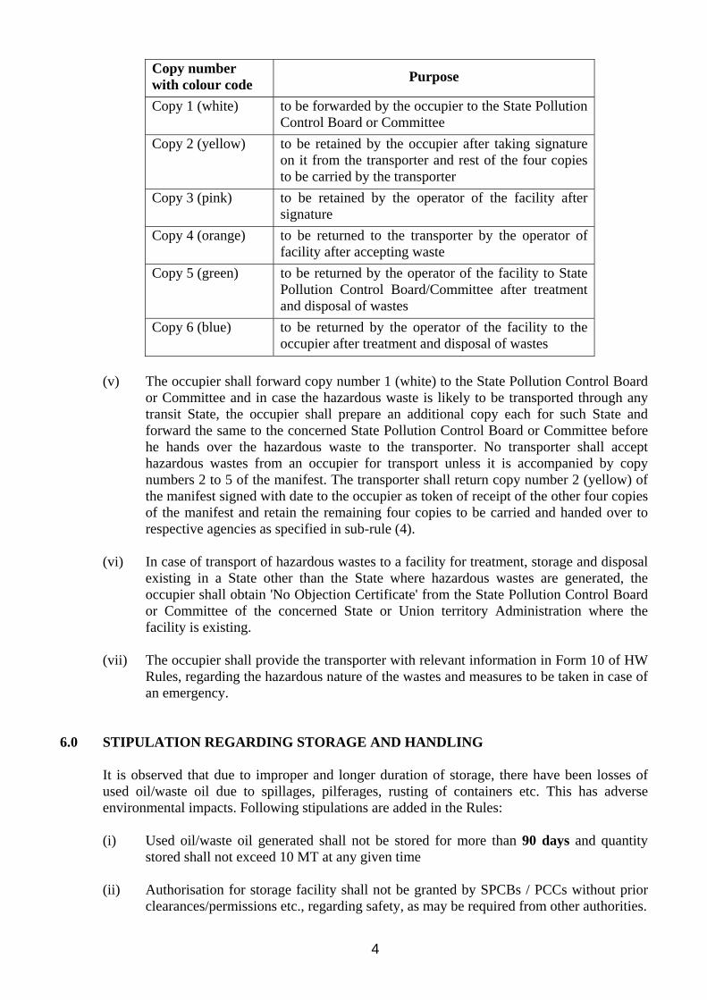
(iv) The occupier shall prepare six copies of the manifest in Form 9 of HW Rules comprising of colour code indicated below (all six copies to be signed by the transporter):
4
Copy number with colour code Purpose
Copy 1 (white) to be forwarded by the occupier to the State Pollution Control Board or Committee
Copy 2 (yellow) to be retained by the occupier after taking signature on it from the transporter and rest of the four copies to be carried by the transporter
Copy 3 (pink) to be retained by the operator of the facility after signature
Copy 4 (orange) to be returned to the transporter by the operator of facility after accepting waste
Copy 5 (green) to be returned by the operator of the facility to State Pollution Control Board/Committee after treatment and disposal of wastes
Copy 6 (blue) to be returned by the operator of the facility to the occupier after treatment and disposal of wastes
(v) The occupier shall forward copy number 1 (white) to the State Pollution Control Board
or Committee and in case the hazardous waste is likely to be transported through any transit State, the occupier shall prepare an additional copy each for such State and forward the same to the concerned State Pollution Control Board or Committee before he hands over the hazardous waste to the transporter. No transporter shall accept hazardous wastes from an occupier for transport unless it is accompanied by copy numbers 2 to 5 of the manifest. The transporter shall return copy number 2 (yellow) of the manifest signed with date to the occupier as token of receipt of the other four copies of the manifest and retain the remaining four copies to be carried and handed over to respective agencies as specified in sub-rule (4).
(vi) In case of transport of hazardous wastes to a facility for treatment, storage and disposal
existing in a State other than the State where hazardous wastes are generated, the occupier shall obtain 'No Objection Certificate' from the State Pollution Control Board or Committee of the concerned State or Union territory Administration where the facility is existing.
(vii) The occupier shall provide the transporter with relevant information in Form 10 of HW
Rules, regarding the hazardous nature of the wastes and measures to be taken in case of an emergency.
6.0 STIPULATION REGARDING STORAGE AND HANDLING It is observed that due to improper and longer duration of storage, there have been losses of used oil/waste oil due to spillages, pilferages, rusting of containers etc. This has adverse environmental impacts. Following stipulations are added in the Rules: (i) Used oil/waste oil generated shall not be stored for more than 90 days and quantity
stored shall not exceed 10 MT at any given time (ii) Authorisation for storage facility shall not be granted by SPCBs / PCCs without prior
clearances/permissions etc., regarding safety, as may be required from other authorities.
5
7.0 TECHNOLOGIES FOR RE-REFINING/RECYCLING The approved technologies and standards have distinctive advantages such as : (a) The re-refining/recycling is done without adding any chemicals or other substances,
which can increase the quantity or toxicity of waste generated in the whole process. (b) The quality of products are of accepted standards for the purposes for which they are
intended.
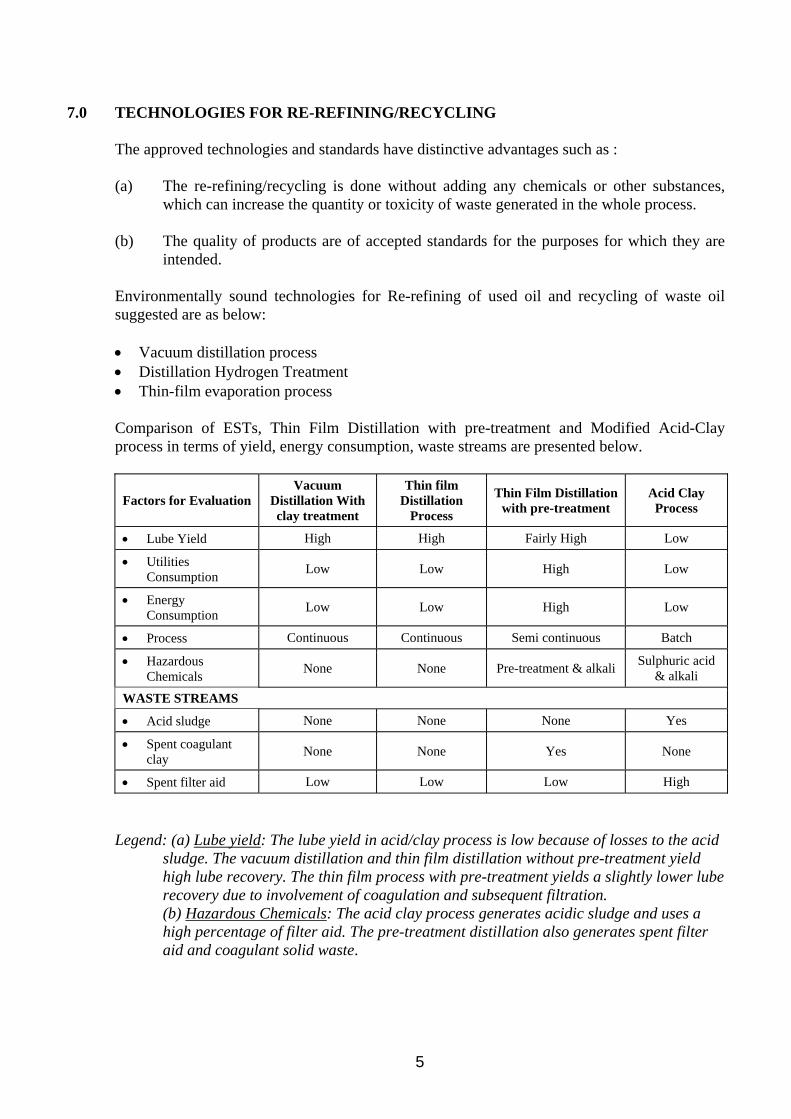
Environmentally sound technologies for Re-refining of used oil and recycling of waste oil suggested are as below: • Vacuum distillation process • Distillation Hydrogen Treatment • Thin-film evaporation process Comparison of ESTs, Thin Film Distillation with pre-treatment and Modified Acid-Clay process in terms of yield, energy consumption, waste streams are presented below.
Factors for Evaluation Vacuum
Distillation With clay treatment
Thin film Distillation
Process
Thin Film Distillation with pre-treatment
Acid Clay Process
• Lube Yield High High Fairly High Low
• Utilities Consumption Low Low High Low
• Energy Consumption Low Low High Low
• Process Continuous Continuous Semi continuous Batch
• Hazardous Chemicals None None Pre-treatment & alkali Sulphuric acid
& alkali
WASTE STREAMS
• Acid sludge None None None Yes
• Spent coagulant clay None None Yes None
• Spent filter aid Low Low Low High
Legend: (a) Lube yield: The lube yield in acid/clay process is low because of losses to the acid sludge. The vacuum distillation and thin film distillation without pre-treatment yield high lube recovery. The thin film process with pre-treatment yields a slightly lower lube recovery due to involvement of coagulation and subsequent filtration.
(b) Hazardous Chemicals: The acid clay process generates acidic sludge and uses a high percentage of filter aid. The pre-treatment distillation also generates spent filter aid and coagulant solid waste.

6
8.0 DISPOSAL OF RESIDUAL WASTES
8.1 Waste Residual Oil (from vacuum distillation & thin film evaporation processes)
(A) Used oil contains largely base oil, degraded additives, carbon, water and in some cases metallic compounds in ppm. Used oil processing in vacuum distillation process is done under varying vacuum and temperature. Under this condition, the water, base oil and some of the bright stock is recovered and the residue will contain the rest of the component of used oil. In this case of used oil collected from India, the quantity of residue will be 12 to 15 percent, whereas good quality used oil may give less than 10% residue.
(B) There is good market potential for using this residue called as “flap oil as a masticating agent in rubber industries manufacturing mats, flaps, beadings etc.. In Kerala & Tamilnadu alone the demand is to the tune of 5000 MT per year. These industries are using pine tar and other expensive substitutes, as we are unable to meet their demand. The application of the residue, commercially known as “Flap Oil”, is as under: Rubber is mixed with Clay, Silicon, Carbon etc., and in order to aid this mixing, Flap Oil is added as a masticating agent. The mixing takes place at 80 to 150 degree C depending on the type of product. Since the Flap Oil is a produce distilled at around 350 degree C at Torr, the mixing temperature of 150 degree will not affect the Flap Oil. The metallic compounds in the Flap Oil is permanently impregnated to the rubber and is rendered harmless. The residue can also be used as asphalt extender. In such application, the residue will get embedded in the tarmac. It is to be stressed that the residue being produced in processes such as Vacuum Distillation or Thin Film Evaporation are having commercial application for disposal in a safe manner. (C) The solid waste generated after pre-treatment and filtration is 17% and heavy residue containing alkaline chemicals is 8% and therefore the disposal is to be carried out by incineration in a common facility. 8.2 Spent Clay
The base oil produced from waste oil is subjected to Activated Alumina Clay treatment. The purpose of this treatment is to improve the colour of base oil. In the process, the clay absorbs traces of aromatics and oxidized oil present in the base oil. This alumina clay got good bonding properties and is used in mixing with rubber in the manufacture of rubber mats. This has also got application to mix the same with the clay used for brick manufacture. In the case of Vacuum Distillation Process and thin Film Evaporation Process, the pH of the Spent Clay is 7.5 and therefore this can be safely used in the above application. This mode of disposal of residue and clay became possible due to the fact that no acid is used in the waste oil reprocessing and hence the base oil remains neutral.

7
9.0 POLICY RELATED ISSUES
1. Disposal of non-acid filter press cake & others
(a) Manifest for tracking of hazardous waste must be put in place. This shall be subject to inspection/surveillance by SPCB/CPCB.
(b) The Solid waste generated in thin film distillation with pre-treatment only in a common facility by way of incineration.
2. Technology options for re-refining/recycling
Irrespective of the technology adopted requirements mentioned in Rule 21 (1) for used and waste oil re-refining / recycling.
3. Waste Oil derived fuel Waste oil derived fuel Specifications need to be declared to prevent unauthorized burning.
4. Re-refined base oil Blending of re-refined base oil produced by EST to be encouraged by major oil blenders.
10.0 REGISTRATION SCHEME TO INCLUDE ALL TYPES OF USED OIL AND WASTE
OIL Justification:
• Used oil and waste oil are hazardous waste as per HW Rules.
• Used oil and waste oil are hazardous wastes as per Basel.
• Waste oil includes used oil as per Custom HS Code.
• Unless regulated it can go to traders.
• Unless regulated it can be used for adulteration.
• Prof. M.G.K.Menon recommended that tank bottom sludge (TBS) waste oil should be included in Registration Scheme.
• The Chairman, CPCB, recommended MoEF to include all types of used oil & waste oil under registration scheme.
• If illegal importer of waste oil is caught by the Customs, it may go to the trader or unauthorized recycler for disposal because it cannot be exported back to the country of origin. Further, if it is not covered under the Registration scheme, how will it be disposed? If waste oil seized by the Customs is not covered under the Registration, this will also lead to the violation of the Hon’ble Supreme Court (SC) Order (CWP No. 657/1995).
• Indigenously generated waste oil [hazardous waste] also needs to be canalised for recycling in an environmentally sound manner. It cannot be left open ended / unregulated in the hands of generators. Therefore, it needs to be covered under Registration.
11.0 FALLACIES IN IMPLEMENTATION OF ESTs
11.1 Vacuum distillation and clay treatment
Distillation is a known technology however every product has its own characteristics and peculiarities; hence the word distillation is a loose and inexact term. Basically Vacuum Distillation is a process, when employed for the purpose of treating of Used Oil or Waste Oil to recover different grades of valuable products and segregating the residual part without addition

8
of any chemical, coagulant or acid to the raw material so that the quality and quantity of wastes are at acceptable levels. This means the quantity of waste generated will be minimum while the quality is of acceptable level so that the same can be safely disposed as a by-product without harming the environment. Vacuum Distillation Process is not a new concept. It is used in many forms to lower the boiling point of a liquid to be distilled.
Used and waste oil processed by this route is basically fractionation done in stages and various fractions are removed at different temperatures and the vacuum levels are adjusted to accommodate the vapour load of the product.
Used and waste oils are a mixture of known and unknown impurities thus they require specialized equipment to process them. A simple distillation column equipped with a receiver cannot do the job as column height, tower packing, reflux ratios, temperature and vacuum calculations are involved. It may further be noted that any oil can be distilled if the temperature is raised to its boiling point. In the case of used and waste oil, it is required to lower the boiling temperature for distillation by creating high vacuum, as otherwise it will pose serious hazardous situations because of the lower self-ignition point of the oil.
One of the essential requirements in any fractional distillation process is that there should be a temperature gradient in the column as well as a reflux ratio to ensure product quality. This is achieved by maintaining correct heat input to the column and the right quantity of input of cooled liquid (Reflux) to the upper part of the column.
There should also be proper process control systems to operate such Plants as it involves controlling of flow, levels, temperature and vacuum of the process at various points. For this, utilities such as steam, cooling water, air system etc. are absolute essentials.
After the notification by MoEF, some of the re-processors of used oil / waste oils, are modifying their process by installing one or more vessels and subjecting these vessels to vacuum.
It has been found that certain units claim to have vacuum distillation with clay treatment, however on inspection it was observed that the units are only capable of removing water and lighter ends. A few units claimed that they were removing water from the used and waste oil by employing oil sealed vacuum pumps and thru water condensers. The heating system was in house made furnaces consisting of a burner and blower. The entrepreneur has missed the very basic concept of vacuum distillation. On further investigation it was found that the plant has been designed to manufacture spray oils, for which the temperature is 150 °C and column design is not equipped to handle heavy fractions.
Another concept being tried to distil the used and waste oils is to install a thick walled vessel and increase the temperature in the range of 400-470 °C, vacuum generation by oil sealed pumps, simple water condensers and 3 receivers to collect water, light oil and lube fraction. The idea being that with such high temperatures the heavy fractions can also be distilled.
There is no denying that certain fraction of the oil can be distilled, however, due to the high temperature employed, it is very clear that the vacuum generation equipment are not suitable for the system load and any failure of vacuum system by way of power failure or mechanical fault can cause an explosion. Moreover at such high temperature the molecules of oil will undergo thermal cracking, thereby degrading the product.

9
Therefore for safe operation of the Plant and to protect the life and property, the operating temperature of the process has to be lower (not exceeding 360 °C). The distillation at this level can be achieved only at a vacuum of not less than 750 mm Hg (6 Torr abs).
11.2 Thin Film Distillation
The theory of this distillation process is usually the procedure of continuous distillation at lower temperatures using high vacuum and once through operation.
Used/waste oils can also be processed in this form of distillation without any pre-treatment or chemicals. Distillation temperatures are normally in the range of 230-300 °C with vacuum levels below 0.01 Torr during distillation.
When used and waste oils can be distilled without employing pre-treatment methods and be distilled directly yielding approximately 10% residue. This is consistent to the reported % of residue obtained in Vacuum Distillation.
To overcome the flaws of equipment design and correct parameters for distillation it seems that pre-treatment technology was added to Thin Film Distillation. Used/waste oils are treated with pre-treatment chemical followed by filtration to remove sludge. The filtered oil is treated to reduce acidity it is obvious that the chemical added was an acidic compound. Further the treated oil is distilled at temperatures of 315-350 °C, which is against the principle of Thin Film Distillation that works on the theory of low temperature and high vacuum.
The waste sludge generated after pre-treatment is 17% and heavy residue after Thin Film Distillation at 8%. From the environmental angle such a process cannot be called EST, when the waste generation is 25% and thus increases the pollutant load.
12.0 PROCESS DESCRIPTION OF ESTs 12.1 VACUUM DISTILLATION PROCESS DESCRIPTION
Introduction:
Waste oil and Used Oil is collected from various sources such as Road Transport garages, Industries, Ships etc. The oil is brought to the factory in leak proof steel barrels or in Tankers and off-loaded at a fully concreted yard or to the steel tank. After ascertaining the quality and quantity of the oil received, it is then pumped into the Waste Oil or Used Oil storage tanks. From theses tanks the oil is pumped into the Process Unit. The Process Plant consists of four distillation columns, first three of them operating in series. Each distillation column, consisting of re-boilers/heaters, coolers and condensers in addition to vacuum system, circulating pumps etc., is called Module. The total system is enclosed and no gas is allowed to leak as these columns are operating under vacuum. The unit is capable of re-refining of Used Oil and for Recycling of Waste Oil. The process conditions are to be adjusted depending on whether the feed is Used Oil or Waste Oil and also depending on the type of waste oil.
For used oil re-refining using Vacuum Distillation with Clay Treatment Process, the parameters found suitable and process description are as follows:

10
1st Module The used oil feed is introduced into this column. The bottom of this column is re-circulated through a re-boiler where the heat is supplied by super heated steam. The vapours from this column are cooled in an overhead condenser where it is condensed and the mixture (water and diesel) are collected in a steel vessel. The top of this vessel is connected to a vacuum pump, which will discharge the gas to a gas header, which leads to the heater for incineration. The 1st module is operating under 600-690 mm Hg vacuum and a bottom temperature of about 170 degree centigrade and top temperature of 40 degree centigrade. The product removed from this column are a mixture of water and diesel which is sent to a tank and a very small quantity of gas (approx. 1 kilo gram per day) is sent to the heater burner for burning. 1st module bottoms, which is free from light fractions and water is fed to the 2nd module. The water is allowed to settle in the tanks and is drained to an oil/water separator.
2nd Module The function of the 2nd Module is to remove from the feed, fractions of base oils (such as SAE 5 and SAE 10 grades). This is accomplished by operating the 2nd Module under a vacuum of 720 mm Hg and a bottom temperature of about 280 degree centigrade. Vacuum is created by evacuating the air leakage from the system using a set of three steam ejectors. The discharge of the ejectors are cooled and condensed. The gas, a mixture of air, steam and a very negligible quantity of hydrocarbon is routed through a condenser to heater burner for incineration. The heat to the column is supplied by circulating the bottoms through a heater coil. The heat is generated in the heater by burning fuel oil.
The product of combustion from the heater is routed to the chimney. Two steams of raw base oil are recovered from the 2nd module and the bottoms from this column are fed to the 3rd module.
3rd Module The function of this Module of this Module is to remove last trace of Base Oil from the Used Oil and the bottoms will be a mixture of bright-stock, carbon and other heavier ingredients present in the Used Oil. This column is operated at maximum vacuum (756 mm Hg) created by a set of four steam electors the outlet of these ejectors are also connected to the condenser as in the case of 2nd and 4th modules. The vapour – a mixture of air, steam and a negligible quantity of Hydro Carbon - is routed through a condenser to the heater/burner for incineration. The heat to the 3rd module is applied by a direct fired heater.
The products drawn from this column are base oils of SAE 20, SAE 30 and SAE 40 grades.
The raw base oils from 2nd and 3rd modules are sent to separate tanks. These raw products are recalled to the Plant for further treatment with activated clay in the 4th module.
4th Module
The raw base oils produced in the 2nd and 3rd modules are intermediate products, which needs further treatment with Activated Alumina Clay. The purpose of clay treatment is to improve the colour of the Base Oil, to give it a golden finish. The oil is mixed with clay in an agitator. The quantity of clay used varies from 2% to 3% depending on the quality of the Raw Base Oil. This mixture is subjected to heating under vacuum. The heat is provided by circulating the mixture through a heater coil as in the case of 2nd and 3rd modules. The vacuum is created by

11
an ejector system consisting of three ejectors. The mixture of exhaust air, steam and a negligible quantity of gas is routed through a condenser and thereafter to the heater for incineration as in the case of the other modules. The operating condition in this column varies depending on the feed-stock. The bottom temperature is kept at 150 degree centigrade to 250 degree centigrade and vacuum of 700 mm Hg. The oil-clay mixture thereafter is cooled and sent for filtration. This clay is stored in a concrete pit. The oil filtered out at the Filter Press is a high value product called Lube Base Stock. This Base-Stock of various viscosity are blended with lubricant additives for converting them into different grades of lubricating oils which are packed in steel drums and other small packs and sold as lubricants.
In order to achieve the above process, various utilities are needed such as steam, cooling water, compressed air etc. Steam is produced in a 2 tons capacity boiler and the fuel oil is burnt to produce the necessary heat in the Boiler. The product of combustion is routed to the common chimney.
Cooling water is supplied from a Cooling Tower System, which re-circulates the cooling water and the heat is removed in the tower.
THE EFFLUENTS
As described above the effluents from this Plant are:
a) Effluent Water This is obtained from Module-1 and is separated in two tanks. This water as well as the
washed down water from tank farm and plant are routed to a specially designed oil/water separator, which separates out all the oil from the water. The recovered oil is pumped back to the Raw Material Storage Tank. The water is used again for washing purpose in the plant. The excess water is routed through a Sand Filter and sent to effluent treatment system. The quantity of this water is 2% to 4% of the feed-stock. The maximum feed to the Plant being 60 tons, the quantity of the water expected at full capacity of the plant is 1200 to 2400 litres a day. This water after treatment is used for make-up in plant cooling system and if excess available will be used for irrigation of plants within our 10 acre compound.
b) Gaseous
The emission gas sources are boiler and the three heaters. In the heaters, in addition to fuel oil, process vapour is also burnt. The quantity of gas from the process (i.e. from the four modules) works out to about 2.2 kilogram per day. This gas is distributed to three heaters for incineration when they are in operation. The plant will give out process gas, only when the process is on and heaters are lit. Therefore, it is obvious that the gas will be incinerated in the lit furnace whenever it is produced.
The only source of Flue Gas (product of combustion) is from the burning of fuel oil. The main contaminants in the flue gas are Sulphur Dioxide and Suspended Particulate Matter. For burning this fuel, pre-heated air is used to ensure complete combustion of the fuel thereby Carbon Monoxide present is eliminated. The Sulphur Dioxide content in flue gas is due to presence of Sulphur in the fuel. Sulphur limit for fuel used is kept at 3% maximum. Excess air is supplied to the combustion chamber to dilute the impurities to a tolerable limit. The total consumption of fuel oil per day is 4.2 Metric Tons. Considering a maximum of 3% Sulphur in fuel, the required height for the chimney is arrived at H=14xQg0.3, where Qg is the emission of Sulphur Dioxide in Kilogram per hour and H is the height in meters. Accordingly the height of the chimney should be 30 metres. We have provided a stack height of 35.5 metres.
12
c) Spent Clay The Spent Clay coming out from the Filter Press is stored in a concrete pit. This clay being of
alumina based, got good bonding properties. It is therefore widely accepted for mixing in with clay in the manufacture of bricks. The spent clay is also used as a filling agent in rubber mat manufacturing. The quantity of clay generated is hardly 1.05 tons per day at full capacity.
There is no other effluent/emission from this Plant.
12.2 VACUUM DISTILLATION UNIT FOR PROCESSING OF WASTE OIL The steps for re-cycling of waste oil are –
Physical separation of solids by filtration, free water by settling, removal of dispersed water by distillation (de-hydration), distilling of waste oil under vacuum and fractionate the oil into various streams by vacuum distillation and final blending of fuel oil for viscosity and specific gravity adjustments.
As can be seen, the initial process of filtration is done by pumping the oil through a series of in-line filters while settling of water is done by storing the waste oil in steam-coiled heated tanks. The water is drained from these tanks to oil-water separators, where the oil traces are recovered. The waste oil is then centrifuged before the same is sent for distillation in the first three columns of vacuum distillation plant. In the first module, the water traces are removed while the second and third modules are used for distillation of waste oil to fractionate them into various distillates, which are sent to storage tanks. These fractions are then blended to the required fuel grades correcting their viscosity and specific gravity. The waste from this process is essentially water which is treated in the effluent system as explained earlier.
12.3 THIN-FILM EVAPORATION PROCESS It is one of the sophisticated methods. This process also should not require any addition of chemicals, acids or coagulant to used oil. The essential components of a unit based on this process are a high precision rotor, which creates a thin film on the heated evaporating surface. The wiping blades spread the material on the heated cylindrical surface, physically pushing the material downward through the slots in a pre-determined pattern.
The distilled material is condensed on the surface of central condenser and is collected in a received and the residue is collected in another receiver as it flows downward along the heated surface.
The product thus obtained is odour less re-refined oil, which is light in colour and free from impurities.
The distillation column operates at above .01 Torr mm Hg and a temperature of 250 – 310 degree C depending on the used/waste oil characteristics while working at full throughput.
The process uses a Thermopac for heating and the fuel used is HSD.
This re-refining process requires minimum external additions, i.e. clay @ 2% - 5% to improve the colour bodies of the distilled oil.

13
13.0 CHECKLIST FOR VERIFICATION OF EST AS PER HW RULES 13.1 CHECK LIST FOR VACUUM DESTILLATION & CLAY TREATMENT PLANT
Details to be supplied by the Unit 1 Name of the Unit : 2 Address : 3 Capacity of the Plant ( KL/annum)
used Oil or Waste Oil :
4 Technology Used : 5 Total Capital investment or Plant &
Machinery :
6 Year of Installation of Plant : 7 No. of Raw material Tanks : Capacity
Used Oil / Waste Oil Treatment Section 1 Area Concreted (Y/N) 2 Drainage system to collect spillage ? (Y/N) 3 Pre - Treatment of Raw Material,
Type of Chemicals Used & Quantity per KL of Used Oil/ Waste Oil
Acid Kg Coagulant/Clay Kg Other Chemicals 4 Settlement Facility (Y/N) 5 Pre Filtration (Y/N) 6 Centrifuge (Y/N) 7 Quantity of Waste generated prior to
introduction of feed to Thin - film Distillation Process

14
Distillation Under Vacuum 1 1st
Column Vacuum generated at No Load
mmHg At Full Feed rate
mmHg
2 2nd Column
Vacuum generated at No Load
mmHg At Full Feed rate
mmHg
3 3rd Column
Vacuum generated at No Load
mmHg At Full Feed rate
mmHg
Distillation Under Vacuum 1 1st
Column Vacuum generated at No Load
mmHg At Full Feed rate
mmHg
2 2nd Column
Vacuum generated at No Load
mmHg At Full Feed rate
mmHg
3 3rd Column
Vacuum generated at No Load
mmHg At Full Feed rate
mmHg
Mechanism Used for generation of Vacuum 1
1st Column Water seal Vacuum Pump (Y/N) mmHg Stream
Ejector (Y/N) No. of
Stages 2
2nd Column Water seal Vacuum Pump (Y/N) mmHg Stream
Ejector (Y/N) No. of
Stages 3
3rd Column Water seal Vacuum Pump (Y/N) mmHg Stream
Ejector (Y/N) No. of
Stages
Source of Process Heat Supplied to 1 1st Column Steam (Y/N) Thermic
Fluid Y/N Direct
Fired Heaters
Y/N
2 2nd Column Steam (Y/N) Thermic Fluid
Y/N Direct Fired Heaters
Y/N
3 3rd Column Steam (Y/N) Thermic Fluid
Y/N Direct Fired Heaters
Y/N
Mechanism Used for generation of Vacuum 1 1st Column Steam (Y/N) Thermic
Fluid (Y/N) Direct Fired
Heaters Y/N
2 2nd Column Steam (Y/N) Thermic Fluid
(Y/N) Direct Fired Heaters
Y/N
3 3rd Column Steam (Y/N) Thermic Fluid
(Y/N) Direct Fired Heaters
Y/N
Temperature maintained in Distillation column
1 1st Column Top Thermic Fluid
(Y/N) oC Bottom oC
2 2nd Column Top Thermic Fluid
(Y/N) oC Bottom oC
3 3rd Column Top Thermic Fluid
(Y/N) oC Bottom oC

15
No. of Streams of Products Recovered
Qty percentage of residue formed for standard type used engine oil from Automotives…………………%
Viscosity of Residue (min) ……………………… Cst at 100 oC Flash Point of Residue
No. of Streams of Products Recovered
Utilities Available 1 Steam Thermic Fluid (Y/N) 2 Cooling Water System Thermic Fluid (Y/N) 3 Plant Air Thermic Fluid (Y/N) 4 Fire Water System 5 Effluent Treatment System Laboratory Equipped to measure
the following
1 Viscosity (Y/N) 2 Flash Point (Y/N) 3 Density (Y/N) 4 TBN 5 Colour Other Background Information 1 No. of Qualified Engineers 2 Technicians / Skilled 3 Unskilled Workers
Maintenance of Records 1 Form 12
Clay Treatment Facility 1 Safe method of handling of Clay to mixer Y/N 2 Qty in percentage clay to be added Y/N 3 Max. Temp to be reached for clay treatment Y/N 4 Existence of safe method for heating Y/N 5 VACUUM applied in Clay Treatment Column Y/N 6 No. of Filter Presses 7 Centrifuge for Filtrate Y/N 8 Spent Clay Storage Facility Y/N Energy consumed by the Unit : Check Previous year's data1 Total Used Oil & Waste Oil Procured / Processed Last year KL
2 Electricity consumed as per record during last year KWH

16
PRODUCTS
1 Are you marketing your Products under own Brand Name ?
2 The Production during last year of Various Products 2a Base Oil KL 2b Light Fuel Oil KL 2c Residue KL 13.2 CHECK LIST FOR THIN - EVAPORATION UNIT Details to be supplied by the Unit 1 Name of the Unit : 2 Address : 3 Capacity of the Plant ( KL/annum) used Oil or Waste Oil : 4 Technology Used : 5 Total Capital investment or Plant & Machinery : Rs. Lakhs 6 Year of Installation of Plant : 7 No. of Raw material Tanks : Nos. Capacity
Used Oil / Waste Oil Treatment Section 1 Concreting of working area. Y/N 2 Drainage system to collect spillage. Y/N
3 Pre - Treatment of Raw Material, Type of Chemicals Used & Quantity per KL of Used Oil/ Waste Oil Other Chemicals Kg
4 Coagulant/Clay Kg
5 Settlement Facility Y/N 6 Pre Filtration Y/N 7 Centrifuge Y/N 8 Quantity of Waste generated prior to introduction of feed to Thin - film Distillation Process
Thin - Film Evaporation Chamber 1 Max. Temperature applied to Used Oil/Waste Oil degrees C. 2 Vacuum mmHg 3 Residual Oil Obtained in percentage to feed 4 Viscosity of Residue @ 100 degree C. 5 Flash point of Residue
Distillation Under Vacuum 1 Column 2 At Full Feed rate mmHg 3 Vacuum generated at No. Load mmHg 4 No. of products streams obtained from distillation process

17
Mechanism Used for generation of Vacuum1 Column 2 Type of Vacuum Pump 3 Stream Ejectors Y/N 4 No. of Stages
Source of Process Heat Supplied to 1 Column 2 Stream Y/N 3 Thermic Fluid
Temperature maintained in Distillation column1 Thin - Film Rotor Top oC Bottom oC 2 Bottom Section Top oC Bottom oC 3 Distillation Section Top oC Bottom oC
No. of Streams of Products Recovered Utilities Available 1 Steam Y/N 2 Cooling Water System Y/N 3 Plant Air Y/N 4 Fire Water System Y/N 5 Effluent Treatment System Y/N
Laboratory Equipped to measure the following1 Viscosity Y/N 2 Flash Point Y/N 3 Density Y/N 4 TBN Y/N 5 Colour Y/N
Other Background Information 1 No. of Qualified Engineers 2 Technicians / Skilled 3 Unskilled Workers
Maintenance of Records 1 Form 12

18
Clay Treatment Facility 1 Safe method of handling of Clay to mixer Y/N 2 Qty in percentage clay to be added Y/N 3 Max. Temp to be reached for clay treatment Y/N 4 Existence of safe method for heating Y/N 5 VACUUM applied in Clay Treatment Column Y/N 6 No. of Filter Presses 7 Centrifuge for Filtrate Y/N 8 Spent Clay Storage Facility Y/N
Energy consumed by the Unit : Check Previous year's data1 Total Used Oil & Waste Oil Procured / Processed Last year KL 2 Electricity consumed as per record during last year KWH
PRODUCTS 1 Are you marketing your Products under own Brand Name? 2 The Production during last year of Various Products 2a Base Oil KL 2b Light Fuel Oil KL 2c Residue KL
---oOo---

Annexure 1
19

Annexure II
20

Annexure III
21

Annexure IV
Schedule - 5*
[See rule 3 (34)]
Specifications for Used oil Suitable for Re-refining
Sr.No. Parameter Maximum Permissible Limit
1 2 3
1. Colour 8 hazen units
2. Water 15%
3. Density 0.85 to 0.95
4. Kinematic Viscosity cSt at 100˚C 1.0 to 32
5. Dilutents 15% vol.
6. Neutralisation No. 3.5 mg KOH/g
7. Saponification value 18 mg KOH/g
8. Total halogens 4000 ppm
9. Polychlorinated biphenyls (PCBs) Below detection limit
10. Lead 100 ppm
11. Arsenic 5 ppm
12. Cadmium + Chromium + Nickle 500ppm
13. Polyaromatic hydrocarbons (PAH) 6%
22

Annexure V
Schedule – 6 [See rule 3(35) and 20(2)]
Specifications for Waste Oil Suitable for Recycling
Sr. No. Parameter Limit
1 2 3
1. Sediment 5% (maximum)
2. Heavy Metals (cadmium +chromium +nickel +lead +arsenic) 605 ppm maximum
3. Polyaromatic hydrocarbons (PAH) 6% maximum
4. Total halogens 4000 ppm maximum
5. Polychlorinated biphenyls (PCBs) Below Detection Limit
---oOo---
23

REFERENCES
1. The Environment (Protection) Act, 1986 promulgated by the Government of India.
2. The Hazardous Wastes (Management and Handling) Rules, 1989, as amended.
3. Technical Guidelines for recycling of used oil issued by the Secretariat of The Basel Convention on trans-boundary movement of hazardous wastes and its control.
4. Report of the High Powered Committee appointed by Supreme Court of India to Study the Hazardous waste management in India (Dr. M.G.K.Menon Committee),1998.
5. Hazardous Wastes (Management and Handling) Rules, 2000, as amended.
6. Hazardous Wastes (Management and Handling ) Rules, 2003, as amended.
7. Hazardous Wastes (Management and Handling ) Rules, 2004, as amended.
8. Waste oil recycling and disposal, NTIS, U.S. Dept of Commerce (PB-236 148) August 1974
9. Conference on waste oil/ used oil recycling / re-refining held at New Delhi March, 2004
10. Directives of the Supreme Court of India in Writ Petition 657 of 1995 dated 14.10.2003
11. Supreme Court Monitoring Committee appointed by the Supreme Court vide order dated 14.10.2003
24