Embed Size (px)
Citation preview
IOSR Journal of Electronics and Communication Engineering (IOSR-JECE)
e-ISSN: 2278-2834,p- ISSN: 2278-8735.Volume 9, Issue 4, Ver. V (Jul - Aug. 2014), PP 50-58 www.iosrjournals.org
www.iosrjournals.org 50 | Page
Implementation of Modified Booth Encoding Multiplier for
signed and unsigned 32 bit numbers
*1Udari Naresh,
2G.Ravi,
3K.Srinivasa Reddy
Assistant Professor, Associate professor Department of Electronics and Communication Engineering Nagole Institute of Technology & Science
Abstract: This paper presents the design and implementation of Modified Booth encoding multiplier for both
signed and unsigned 32 - bit numbers multiplication. The already existed Modified Booth Encoding multiplier and the Baugh-Wooley multiplier perform multiplication operation on signed numbers only. Whereas the array
multiplier and Braun array multipliers perform multiplication operation on unsigned numbers only. Thus, the
requirement of the modern computer system is a dedicated and very high speed unique multiplier unit for signed
and unsigned numbers. Therefore, this paper presents the design and implementation of SUMBE multiplier. The
modified Booth Encoder circuit generates half the partial products in parallel. By extending sign bit of the
operands and generating an additional partial product the SUMBE multiplier is obtained. The Carry Save
Adder (CSA) tree and the final Carry Look ahead (CLA) adder used to speed up the multiplier operation. Since
signed and unsigned multiplication operation is performed by the same multiplier unit the required hardware and the chip area reduces and this in turn reduces power dissipation and cost of a system.
Index Terms: Modified Booth Encoding multiplier, Baugh-Wooley multiplier, array multiplier, CSA, CLA
Partial product, Signed-unsigned.
I. Introduction Multiplication is a most commonly used operation in many computing systems. Infact multiplication is
nothing but addition since, multiplicand adds to itself multiplier number of times gives the multiplication value between multiplier and multiplicand. But considering the fact that this kind of implementation really takes huge
hardware resources and the circuit operates at utterly low speed. In order to address this so many ideas have
been presented so far for the last three decades. Each one is aimed at particular improvement according to the
requirement. One may be aimed at high clock speeds and another maybe aimed for low power or less area
occupation. Either way ultimate job is to come up with an efficient architecture which can address three
constraints of VLSI speed, area, and power. Among these three speeds is the one which requires special
attention. If we observe closely multiplication operation involves two steps one is producing partial products
and adding these partial products [3]. Thus, the speed of a multiplier hardly depends on how fast generate the partial products and how fast we can add them together. If the numbers of partial products to be generated are of
less than it is indirectly means that we have achieved the speed in generating partial products. Booth‟s
algorithms are meant for this only. To speed up the addition among the partial products we need fast adder
architectures. Since the multipliers have a significant impact on the performance of the entire system, many high
performance algorithms and architectures have been proposed [1-12]. The very high speed and dedicated
multipliers are used in pipeline and vector computers.
The high speed Booth multipliers and pipelined Booth multipliers are used for digital signal processing
(DSP) applications such as for multimedia and communication systems. High speed DSP computation applications such as Fast Fourier transform (FFT) require additions and multiplications. The conventional
modified Booth encoding (MBE) generates an irregular partial product array because of the extra partial product
bit at the least significant bit position of each partial product row. Therefore papers [4] presents a simple
approach to generate a regular partial product array with fewer partial product rows and negligible overhead,
thereby lowering the complexity of partial product reduction and reducing the area, delay, and power of MBE
multipliers. But the drawback of this multiplier is that it functions only for signed number operands.
The modified-Booth algorithm is extensively used for high-speed multiplier circuits. Once, when array
multipliers were used, the reduced number of generated partial products significantly improved multiplier performance. In designs based on reduction trees with logarithmic logic depth, however, the reduced number of
partial products has a limited impact on overall performance. The Baugh-Wooley algorithm [7,8,9] is a different
scheme for signed multiplication, but is not so widely adopted because it may be complicated to deploy on
irregular reduction trees. Again the Baugh-Wooley algorithm is for only signed number multiplication. The
array multipliers and Braun array multipliers [10] operates only on the unsigned numbers. Thus, the requirement
of the modern computer system is a dedicated and very high speed multiplier unit that can perform
multiplication operation on signed as well as unsigned numbers. In this paper we designed and implemented a
Implementation of Modified Booth Encoding Multiplier for signed and unsigned 32 bit numbers
www.iosrjournals.org 51 | Page
dedicated multiplier unit that can perform multiplication operation on both signed and unsigned numbers, and
this multiplier is called as SUMBE multiplier.
II. Conventional Modified Booth Multiplier A. Algorithm of the Modified Booth Multiplier
Multiplication consists of three steps: 1) the first step to generate the partial products; 2) the second
step to add the generated partial products until the last two rows are remained; 3) the third step to compute the
final multiplication results by adding the last two rows. The modified Booth algorithm reduces the number of partial products by half in the first step. We used the modified Booth encoding (MBE) scheme proposed in [2].
It is known as the most efficient Booth encoding and decoding scheme. To multiply X by Y using the modified
Booth algorithm starts from grouping Y by three bits and encoding into one of {-2, -1, 0, 1, 2}. Table I shows
the rules to generate the encoded signals by MBE scheme and Fig. 1 (a) shows the corresponding logic diagram.
The Booth decoder generates the partial products using the encoded signals as shown in Fig. 1(b).
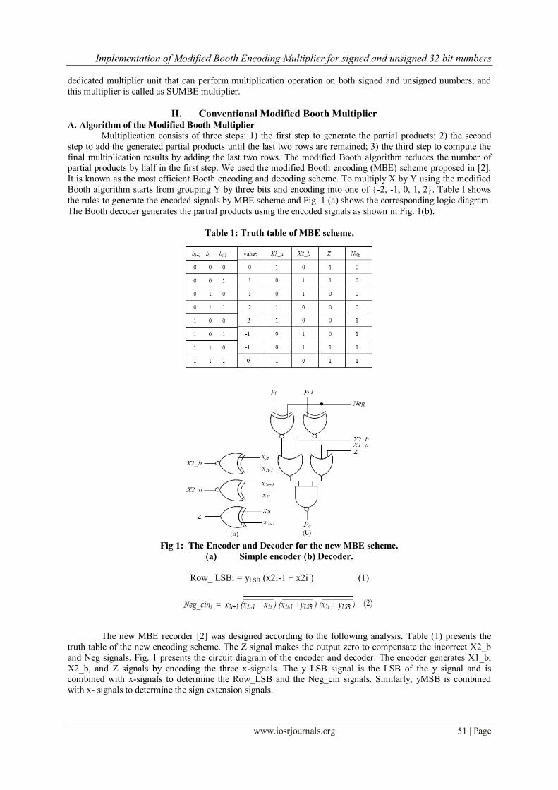
Table 1: Truth table of MBE scheme.
Fig 1: The Encoder and Decoder for the new MBE scheme.
(a) Simple encoder (b) Decoder.
Row_ LSBi = yLSB (x2i-1 + x2i ) (1)
The new MBE recorder [2] was designed according to the following analysis. Table (1) presents the
truth table of the new encoding scheme. The Z signal makes the output zero to compensate the incorrect X2_b
and Neg signals. Fig. 1 presents the circuit diagram of the encoder and decoder. The encoder generates X1_b,
X2_b, and Z signals by encoding the three x-signals. The y LSB signal is the LSB of the y signal and is combined with x-signals to determine the Row_LSB and the Neg_cin signals. Similarly, yMSB is combined
with x- signals to determine the sign extension signals.
Implementation of Modified Booth Encoding Multiplier for signed and unsigned 32 bit numbers
www.iosrjournals.org 52 | Page
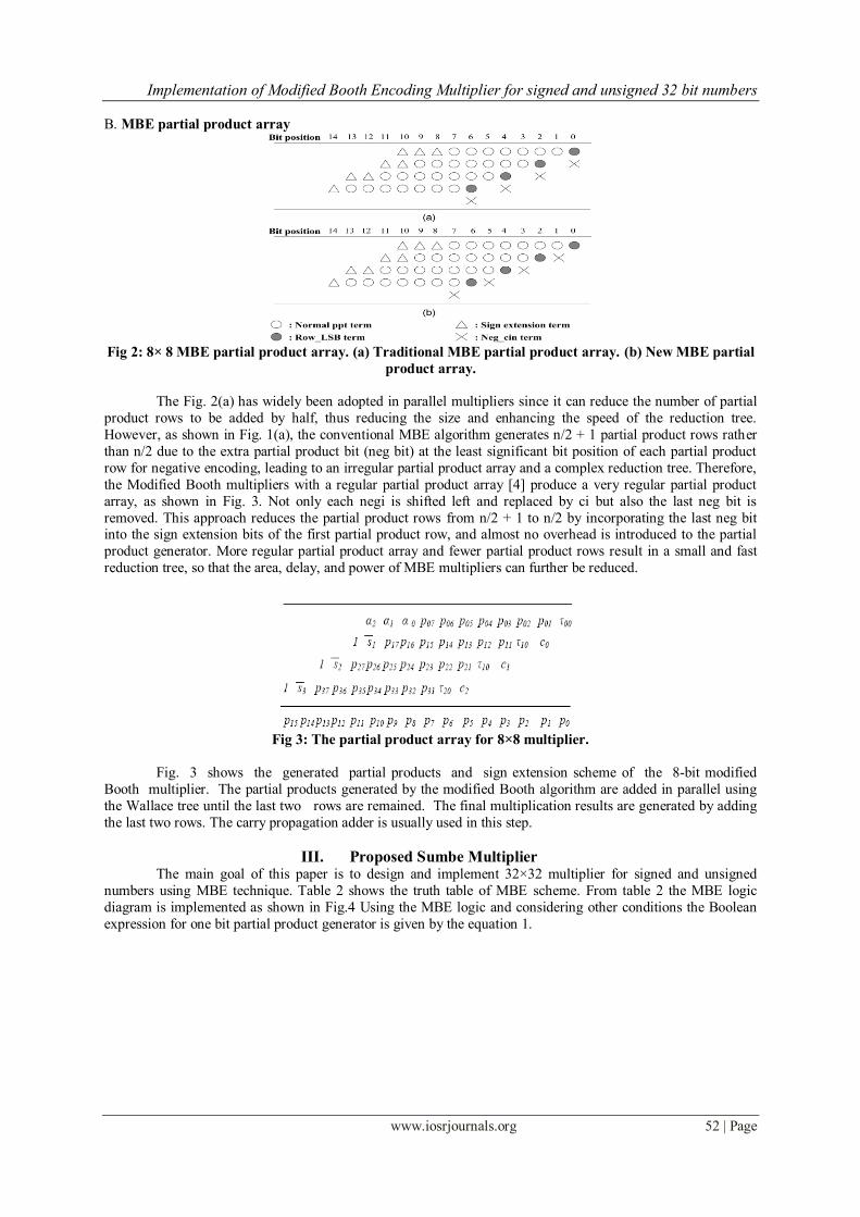
B. MBE partial product array
Fig 2: 8× 8 MBE partial product array. (a) Traditional MBE partial product array. (b) New MBE partial
product array.
The Fig. 2(a) has widely been adopted in parallel multipliers since it can reduce the number of partial
product rows to be added by half, thus reducing the size and enhancing the speed of the reduction tree.
However, as shown in Fig. 1(a), the conventional MBE algorithm generates n/2 + 1 partial product rows rather
than n/2 due to the extra partial product bit (neg bit) at the least significant bit position of each partial product
row for negative encoding, leading to an irregular partial product array and a complex reduction tree. Therefore,
the Modified Booth multipliers with a regular partial product array [4] produce a very regular partial product
array, as shown in Fig. 3. Not only each negi is shifted left and replaced by ci but also the last neg bit is
removed. This approach reduces the partial product rows from n/2 + 1 to n/2 by incorporating the last neg bit into the sign extension bits of the first partial product row, and almost no overhead is introduced to the partial
product generator. More regular partial product array and fewer partial product rows result in a small and fast
reduction tree, so that the area, delay, and power of MBE multipliers can further be reduced.
Fig 3: The partial product array for 8×8 multiplier.
Fig. 3 shows the generated partial products and sign extension scheme of the 8-bit modified
Booth multiplier. The partial products generated by the modified Booth algorithm are added in parallel using
the Wallace tree until the last two rows are remained. The final multiplication results are generated by adding
the last two rows. The carry propagation adder is usually used in this step.
III. Proposed Sumbe Multiplier
The main goal of this paper is to design and implement 32×32 multiplier for signed and unsigned
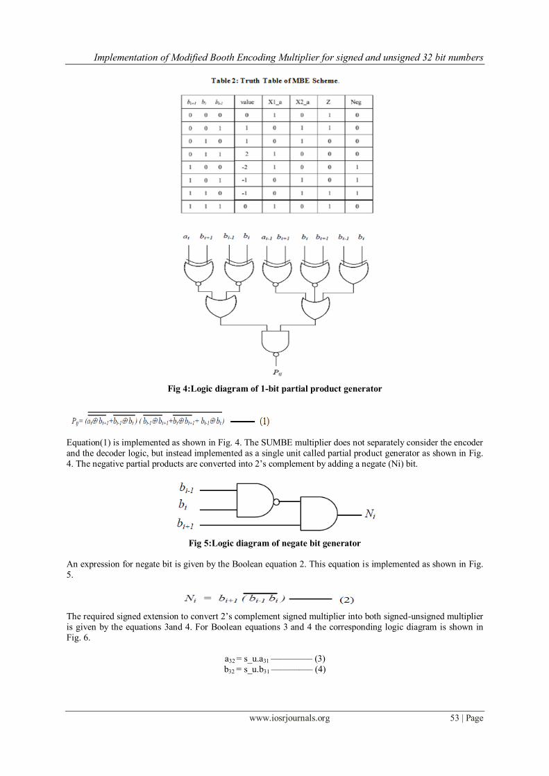
numbers using MBE technique. Table 2 shows the truth table of MBE scheme. From table 2 the MBE logic
diagram is implemented as shown in Fig.4 Using the MBE logic and considering other conditions the Boolean
expression for one bit partial product generator is given by the equation 1.
Implementation of Modified Booth Encoding Multiplier for signed and unsigned 32 bit numbers
www.iosrjournals.org 53 | Page
Fig 4:Logic diagram of 1-bit partial product generator
Equation(1) is implemented as shown in Fig. 4. The SUMBE multiplier does not separately consider the encoder
and the decoder logic, but instead implemented as a single unit called partial product generator as shown in Fig.
4. The negative partial products are converted into 2‟s complement by adding a negate (Ni) bit.
Fig 5:Logic diagram of negate bit generator
An expression for negate bit is given by the Boolean equation 2. This equation is implemented as shown in Fig.
5.
The required signed extension to convert 2‟s complement signed multiplier into both signed-unsigned multiplier
is given by the equations 3and 4. For Boolean equations 3 and 4 the corresponding logic diagram is shown in
Fig. 6.
a32 = s_u.a31 ––––––––– (3)
b32 = s_u.b31 ––––––––– (4)
Implementation of Modified Booth Encoding Multiplier for signed and unsigned 32 bit numbers
www.iosrjournals.org 54 | Page
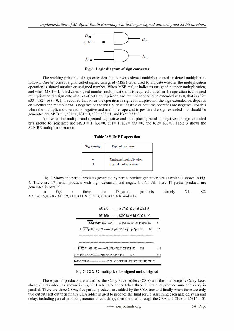
Fig 6: Logic diagram of sign converter
The working principle of sign extension that converts signed multiplier signed-unsigned multiplier as
follows. One bit control signal called signed-unsigned (MSB) bit is used to indicate whether the multiplication
operation is signed number or unsigned number. When MSB = 0, it indicates unsigned number multiplication,
and when MSB = 1, it indicates signed number multiplication. It is required that when the operation is unsigned
multiplication the sign extended bit of both multiplicand and multiplier should be extended with 0, that is a32=
a33= b32= b33= 0. It is required that when the operation is signed multiplication the sign extended bit depends
on whether the multiplicand is negative or the multiplier is negative or both the operands are negative. For this when the multiplicand operand is negative and multiplier operand is positive the sign extended bits should be
generated are MSB = 1, a31=1, b31= 0, a32= a33 =1, and b32= b33=0.
And when the multiplicand operand is positive and multiplier operand is negative the sign extended
bits should be generated are MSB = 1, a31=0, b31= 1, a32= a33 =0, and b32= b33=1. Table 3 shows the
SUMBE multiplier operation.
Table 3: SUMBE operation
Fig. 7. Shows the partial products generated by partial product generator circuit which is shown in Fig.
4. There are 17-partial products with sign extension and negate bit Ni. All these 17-partial products are
generated in parallel.
In Fig. 7 there are 17-partial products namely X1, X2, X3,X4,X5,X6,X7,X8,X9,X10,X11,X12,X13,X14,X15,X16 and X17.
Fig 7: 32 X 32 multiplier for signed and unsigned
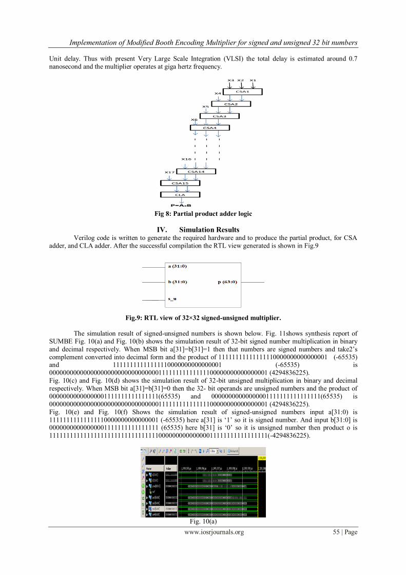
These partial products are added by the Carry Save Adders (CSA) and the final stage is Carry Look
ahead (CLA) adder as shown in Fig. 8. Each CSA adder takes three inputs and produce sum and carry in
parallel. There are three CSAs, five partial products are added by the CSA tree and finally when there are only
two outputs left out then finally CLA adder is used to produce the final result. Assuming each gate delay an unit delay, including partial product generator circuit delay, then the total through the CSA and CLA is 15+16 = 31
Implementation of Modified Booth Encoding Multiplier for signed and unsigned 32 bit numbers
www.iosrjournals.org 55 | Page
Unit delay. Thus with present Very Large Scale Integration (VLSI) the total delay is estimated around 0.7
nanosecond and the multiplier operates at giga hertz frequency.
Fig 8: Partial product adder logic
IV. Simulation Results
Verilog code is written to generate the required hardware and to produce the partial product, for CSA
adder, and CLA adder. After the successful compilation the RTL view generated is shown in Fig.9
Fig.9: RTL view of 32×32 signed-unsigned multiplier.
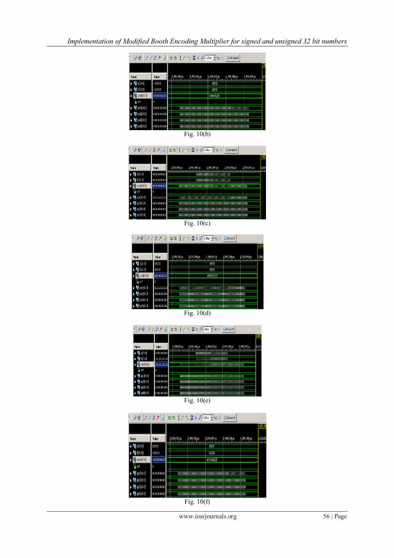
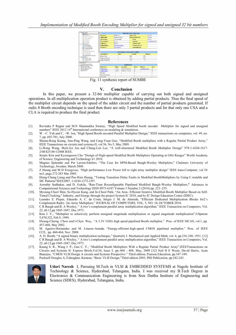
The simulation result of signed-unsigned numbers is shown below. Fig. 11shows synthesis report of
SUMBE Fig. 10(a) and Fig. 10(b) shows the simulation result of 32-bit signed number multiplication in binary
and decimal respectively. When MSB bit a[31]=b[31]=1 then that numbers are signed numbers and take2‟s
complement converted into decimal form and the product of 11111111111111110000000000000001 (-65535) and 11111111111111110000000000000001 (-65535) is
0000000000000000000000000000000011111111111111100000000000000001 (4294836225).
Fig. 10(c) and Fig. 10(d) shows the simulation result of 32-bit unsigned multiplication in binary and decimal
respectively. When MSB bit a[31]=b[31]=0 then the 32- bit operands are unsigned numbers and the product of
00000000000000001111111111111111(65535) and 00000000000000001111111111111111(65535) is
0000000000000000000000000000000011111111111111100000000000000001 (4294836225).
Fig. 10(e) and Fig. 10(f) Shows the simulation result of signed-unsigned numbers input a[31:0) is
11111111111111110000000000000001 (-65535) here a[31] is „1‟ so it is signed number. And input b[31:0] is 00000000000000001111111111111111 (65535) here b[31] is „0‟ so it is unsigned number then product o is
1111111111111111111111111111111100000000000000011111111111111111(-4294836225).
Fig. 10(a)
Implementation of Modified Booth Encoding Multiplier for signed and unsigned 32 bit numbers
www.iosrjournals.org 56 | Page
Fig. 10(b)
Fig. 10(c)
Fig. 10(d)
Fig. 10(e)
Fig. 10(f)
Implementation of Modified Booth Encoding Multiplier for signed and unsigned 32 bit numbers
www.iosrjournals.org 57 | Page
Fig. 11 synthesis report of SUMBE
V. Conclusion
In this paper, we present a 32-bit multiplier capable of carrying out both signed and unsigned
operations. In all multiplication operation product is obtained by adding partial products. Thus the final speed of the multiplier circuit depends on the speed of the adder circuit and the number of partial products generated. If
radix 8 Booth encoding technique is used then there are only 3 partial products and for that only one CSA and a
CLA is required to produce the final product.
References [1]. Ravindra P Rajput and M.N Shanmukka Swamy, “High Speed Modified booth encoder Multiplier for signed and unsigned
numbers” IEEE 2012 14th International conference on modeling & simulation.
[2]. W. –C. Yeh and C. –W. Jen, “High Speed Booth encoded Parallel Multiplier Design,” IEEE transactions on computers, vol. 49, no.
7, pp. 692-701, July 2000.
[3]. Shiann-Rong Kuang, Jiun-Ping Wang, and Cang-Yuan Guo, “Modified Booth multipliers with a Regular Partial Product Array,”
IEEE Transactions on circuits and systems-II, vol 56, No 5, May 2009.
[4]. Li-Rong Wang, Shyh-Jye Jou and Chung-Len Lee, “A well-structured Modified Booth Multiplier Design” 978-1-4244-1617-
2/08/$25.00 ©2008 IEEE.
[5]. Soojin Kim and Kyeongsoon Cho “Design of High-speed Modified Booth Multipliers Operating at GHz Ranges” World Academy
of Science, Engineering and Technology 61 2010.
[6]. Magnus Sjalander and Per Larson-Edefors. “The Case for HPM-Based Baugh-Wooley Multipliers,” Chalmers University of
Technology, Sweden, March 2008.
[7]. Z Haung and M D Ercegovac, “High performance Low Power left to right array multiplier design” IEEE trans.Computer, vol 54
no3, page 272-283 Mar 2005.
[8]. Hsing-Chung Liang and Pao-Hsin Huang, “Testing Transition Delay Faults in Modified BoothMultipliers by Using C-testable and
SIC Patterns”IEEE2007, 1-4244-1272-2/07.
[9]. Aswathy Sudhakar, and D. Gokila, “Run-Time Reconfigurable Pipelined Modified Baugh-Wooley Multipliers,” Advances in
Computational Sciences and Technology ISSN 0973-6107 Volume 3 Number 2 (2010) pp. 223–235.
[10]. Myoung-Cheol Shin, Se-Hyeon Kang, and In-Cheol Park, “An Area- Efficient Iterative Modified-Booth Multiplier Based on Self-
Timed Clocking,” Industry, and Energy through the project System IC 2010, and by IC Design Education Center (IDEC).
[11]. Leandro Z. Pieper, Eduardo A. C. da Costa, Sérgio J. M. de Almeida, “Efficient Dedicated Multiplication Blocks for2´s
Complement Radix- 2m Array Multipliers,” JOURNAL OF COMPUTERS, VOL. 5, NO. 10, OCTOBER 2010.
[12]. C R Baugh and B. A Wooley, “ A two‟s complement parallel array multiplication algorithm,” IEEE Transaction on Computers, Vol.
22, n0.12,pp 1045-1047, Dec.1973.
[13]. Kim J. Y., “Multiplier to selectively perform unsigned magnitude multiplication or signed magnitude multiplication”,USpatent
5,870,322, Feb 9, 1999.
[14]. Hwang-Cherng Chow and I-Chyn Wey, “A 3.3V 1GHz high speed pipelined Booth multiplier,” Proc. of IEEE ISCAS, vol.1, pp.
457-460, May 2002.
[15]. M. Aguirre-Hernandez and M. Linarse-Aranda, “Energy-efficient high-speed CMOS pipelined multiplier,” Proc. of IEEE
CCE, pp. 460-464, Nov. 2008.
[16]. A. D. Booth, “A signed binary multiplication technique,” Quarterly J. Mechanical and Applied Math, vol. 4, pp.236-240, 1951. [12]
C R Baugh and B. A Wooley, “ A two‟s complement parallel array multiplication algorithm,” IEEE Transaction on Computers, Vol.
22, n0.12,pp 1045-1047, Dec.1973.
[17]. Kuang S. R., Wang J. P., Guo C. Y., “Modified Booth Multipliers With a Regular Partial Product Array”,IEEETransactions on
Circuits and Systems II: Express Briefs,Vol.56, Issue 5, pp.:404 - 408, May, 2009 [12] Neil H E Weste, David Harris, Ayan
Banerjee, “CMOS VLSI Design A circuits and Systems Perspective ” Third edition, Pearson Education, pp.347-349.
[18]. Pucknell Douglas A, Eshraghan, Kamran, “Basic VLSI Design,”Third edition 2003, PHI Publication, pp.242-243.
Udari Naresh I, Pursuing M.Tech in VLSI & EMBEDDED SYSTEMS at Nagole Institute of Technology & Science, Hyderabad, Telangana, India. I was received my B.Tech Degree in
Electronics & Communication Engineering is from Sree Dattha Institute of Engineering and
Science (SDES), Hyderabad, Telangana, India.

Implementation of Modified Booth Encoding Multiplier for signed and unsigned 32 bit numbers
www.iosrjournals.org 58 | Page
K. SRINIVASA REDDY is Associate Professor of the Electronics and Communication
Engineering, Nagole Institute of Technology and Science,Hyderabad .He received his B.Tech degree in Electronics and Communication Engineering from JNT University, Hyderabad, and
M.Tech degree in Embedded Systems from JNT University, Hyderabad.. He is a member of The
International Association of Engineers (IAENG). He has about 6 publications in National and
International Journals.
G.RAVI KUMAR is Assistant Professor of the Electronics and Communication Engineering,
Nagole Institute of Technology and Science,Hyderabad. He was completed M.Tech in VLSI
DESIGN at Sarada Institute of Technology and Science, Khammam, Telangana, India. He
received B.Tech degree in Electronics & Communication Engineering is from Anurag
Engineering college, Kodada, Telangana,India.