Embed Size (px)
Citation preview
Implementation of NASAMaterials & Processes Requirementsat the Goddard Space Flight Center
Chuck PowersAssociate Branch Head, Code 541
http://materials.gsfc.nasa.gov/
July 23, 2009
https://ntrs.nasa.gov/search.jsp?R=20090027819 2018-05-29T12:13:50+00:00Z
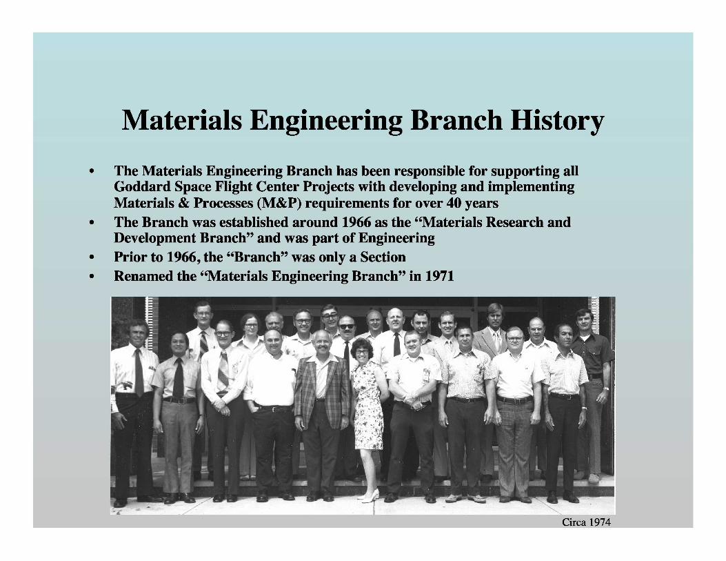
Circa 1974
Materials Engineering Branch History
• The Materials Engineering Branch has been responsible for supporting all' Goddard Space Flight Center Projects with developing and implementing
Materials & Processes (M&P) requirements for over 40 years• The Branch was established around 1966 as the “Materials Research and
Development Branch” and was part of Engineering• Prior to 1966, the “Branch” was only a Section• Renamed the “Materials Engineering Branch” in 1971
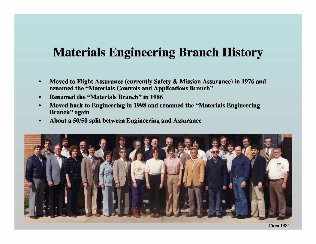
Circa 1984
Materials Engineering Branch History
' • Moved to Flight Assurance (currently Safety & Mission Assurance) in 1976 andrenamed the “Materials Controls and Applications Branch”
• Renamed the “Materials Branch” in 1986• Moved back to Engineering in 1998 and renamed the “Materials Engineering
Branch” again• About a 50/50 split between Engineering and Assurance
Early History of M&P Requirements at GSFC
' • As early as 1966, Branch members were reviewing M&P lists• The primary focus of these early reviews was outgassing, contamination, usage and
previous materials-related lessons learned• • Following the move to Flight Assurance in 1976, consolidated M&P requirements
were developed as part of the Guidelines for Standard Payload AssuranceRequirements (SPAR) for Orbital Projects
• SPAR-3 (the final version of these requirements) was released in 1990, with the lastrevision released in 1992
• SPAR-3 called out requirements for material usage, flammability & toxicoffgassing, vacuum outgassing, shelf life control of polymers, stress corrosion
• cracking susceptibility for metals, fastener integrity, lubrication, materialprocesses, welding & brazing, and material procurement
• GSFC Management Instruction (GMI) 5340.1, Implementation of the GoddardSpace Flight Center (GSFC) Materials and Processes Program was also released1987
• GMI 5340.1 described the roles and responsibilities of the Project Manager, FlightAssurance Manager (now called CSOs), the Materials Engineering Branch, and theSystem Safety Branch in implementing a M&P program
ISO-9001 and Beyond
• In 1999, 300-PG-7120.2.1, Mission Assurance Guidelines (MAG) Implementation and300-PG-7120.2.2, Mission Assurance Guidelines (MAG) for Tailoring to the needs of
• GSFC Projects replaced SPAR-3• Eventually 541-PG-7120.2.1, Materials Assurance Engineering Support Guidelines
for Goddard Space Flight Center (GSFC) Projects replaced GMI-5340.1 in 2003• In 2006, the NASA M&P Working Group initiated the development of a standard
set of M&P requirements for all NASA missions• The initial goal of this activity was to develop a set of standardized requirements
for the Constellation Program since multiple NASA Centers were supportingConstellation
• • An interim version of NASA-STD-6016, Standard Materials and ProcessesRequirements for Spacecraft was released in September 2006
• • The final consensus version was released in July 2008, with some modifications toaccommodate requirements for non-human rated missions, which tend to be lessstringent in some areas than the requirements for human-rated missions
• The consensus version of NASA-STD-6016 in currently being incorporated in themission assurance requirements for GSFC missions
General M&P requirements in NASA-STD-6016
' • Materials will be selected to meet worst-case operational requirements• Non-flight materials used to process flight hardware will not cause
' degradation of flight hardware• A Materials and Processes Selection, Control, and Implementation Plan
' shall be developed and implemented by the organization responsible forthe spacecraft flight hardware
• Design drawings and revisions shall contain a M&P approval block• All M&P shall be defined by standards and specifications• Each hardware provider shall establish a M&P Control Board
- The responsible NASA M&P organization shall be a active and votingmember of the board (with veto power)
• M&P usage will be documented in a Materials Identification and UsageList (MIUL)
• M&P that do not meet the requirements of NASA-STD-6016 shall be' documented using a Materials Usage Agreement (MUA)
Specific M&P Requirements from NASA-STD-6016
• Design allowables for structural materials shall come from Metallic MaterialsProperties Development and Standardization (MMPDS) and/or the MIL-HDBK-17
• Materials shall meet the requirements of NASA-STD-6001, Flammability,Offgassing, and Compatibility Requirements and Test Procedures
• MSFC-STD-3029, Guidelines for the Selection of Metallic Materials for StressCorrosion Cracking Resistance in Sodium Chloride Environments, shall be used toselect metallic materials to control stress corrosion cracking of metallic materials insea and air environments
• Nonmetallic materials should be low outgassing per ASTM-E-595(percent total mass loss <1.0, and percent collected volatile condensable <0.1)
• Materials exposed to the space environment shall be selected to perform in thatenvironment (atomic oxygen, solar ultraviolet radiation, ionizing radiation, plasma,
• vacuum, thermal cycling, and contamination)• Additionally, there are specific requirements for processes such as forging, castings,
adhesive bonding, welding, brazing and soldering• There are also specific requirements for nondestructive evaluation (NDE), residual
stress mitigation, sandwich assemblies, corrosion prevention, hydrogenembrittlement, fasteners, contamination control and packaging
GSFC-Specific Modifications to NASA-STD-6016
' • For GSFC Non-human Rated Missions (which covers most of GSFC work),the M&P requirements in NASA-STD-6016 are tailored as follows:- The developer is not required to have M&P drawing sign off- The developer may use GSFC forms or the developer’s equivalent forms in lieu ofthe MAPTIS format for the MIUL- The developer does not need to follow the 3 tier MUA approach
' - The developer may use the GSFC outgassing database in addition to MAPTIS(http://outgassing.nasa.gov)
• - The developer shall use AFPCMAN91-710V3 Range Safety Users RequirementsManual section 10.1 in place of NASA-STD-6001- The developer shall qualify all lubricated mechanisms either by life testing in
' accordance with a life test plan or through heritage with an identical mechanism• used in an identical application
- The developer only needs to implement a Non-Destructive Evaluation Plan forfracture critical flight hardware- The developer shall use 541-PG-8072.1.2, GSFC Fastener Integrity Requirements inplace of NASA-STD-6008
• For Human-rated Missions, GSFC generally follows all the requirementscalled out in NASA-STD-6016
Additional M&P-related Requirements
• In addition to the M&P requirements from NASA-STD-6016,GSFC implements M&P-related requirements from the followingdocuments:
- NPD 8730.2C, NASA Parts Policy(Applies to mechanical parts such as fasteners, bearings, studs,pins, rings, shims, piping components, valves, springs, brackets,clamps, and spacers. Also applies to manufacturing materialsaffecting the performance and acceptability of parts such asplating, solder, and weld filler material.)
- NPR 8735.1B, Procedures For Exchanging Parts, Materials, andSafety Problem Data Utilizing the Government-Industry DataExchange Program (GIDEP) and NASA Advisories
Additional M&P-related Requirements
• AFSPCMAN 91-710V3, Air Force Space Command Manual(Use the least flammable and least toxic materials)
• Institute for Printed Circuits Standards- IPC-2221, Generic Standard on Printed Board Design- IPC-2222, Sectional Design Standard for Rigid Organic PrintedBoards- IPC-2223, Sectional Design Standard for Flexible Printed Boards- IPC A-600, Acceptability of Printed Boards (Class 3 requirements)- IPC-6011, Generic Performance SpeciÞcation for Printed Boards(Class 3 requirements)- IPC-6012, QualiÞcation and Performance SpeciÞcation for RigidPrinted Boards (Class 3/A requirements)- IPC-6013, QualiÞcation and Performance SpeciÞcation forFlexible Printed Boards (Class 3 requirements)
Printed Wiring Board Coupon Inspection
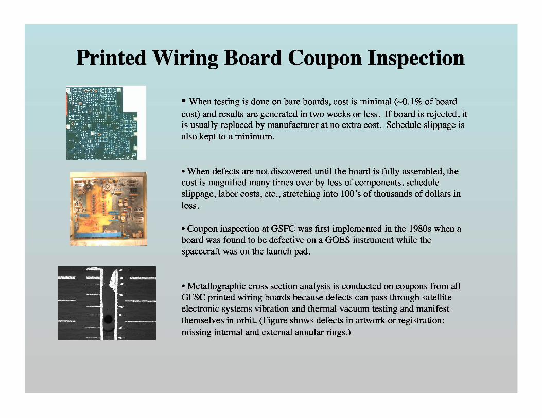
• When testing is done on bare boards, cost is minimal (~0.1 % of boardcost) and results are generated in two weeks or less. If board is rejected, itis usually replaced by manufacturer at no extra cost. Schedule slippage isalso kept to a minimum.
• When defects are not discovered until the board is fully assembled, thecost is magnified many times over by loss of components, scheduleslippage, labor costs, etc., stretching into 100’s of thousands of dollars inloss.
• Coupon inspection at GSFC was first implemented in the 1980s when aboard was found to be defective on a GOES instrument while thespacecraft was on the launch pad.
• Metallographic cross section analysis is conducted on coupons from allGFSC printed wiring boards because defects can pass through satelliteelectronic systems vibration and thermal vacuum testing and manifestthemselves in orbit. (Figure shows defects in artwork or registration:missing internal and external annular rings.)
So how does the Materials Engineering Branchhelp GSFC Projects meet these requirements?
• A Materials & Processes Engineer (MPE) is assigned to each GSFC Project- MPEs were formerly called Materials Assurance Engineers (MAEs)
• Early in a mission, the MPE supports the Chief Safety & Mission Assurance Officer(CSO) in developing Materials and Processes requirements
• The MPE reviews (and approves) the Materials and Processes Control Plan' submitted by the developer for out-of-house missions
• The MPE develops and implements the Materials and Processes Control Plan forin-house missions
• The MPE reviews (and approves) all Materials and Processes used on a spacecraftor instrument- By participating on the Parts, Materials and Processes Control Boards (PMPCB)or MPCB (this is typical with out-of-house missions)- By reviewing Materials and Processes Lists (most common)- By reviewing Drawings (can be an effective approach, but may also be timeconsuming, typical for in-house Shuttle work)- By meeting with subsystem leads (sometimes necessary for in-house projects)- By auditing a subsystem suppliers (very occasionally)
So how does the Materials Engineering Branch help GSFCProjects meet these requirements? (continued)
• The MPE reviews materials-related GIDEP Alerts and Advisories• Branch members attend design reviews (PDR, CDR, etc.)• Branch members review (and approve) Materials Usage Agreements (MUAs) or
Waivers concerning material issues• Branch Metallurgists review (and approve) MUAs related to stress corrosion
cracking• Branch members audits subcontractor facilities as requested• Branch members review (and approve) procurements as requested• Branch members work with discipline engineers to address materials- and
processes-related design issues- Supported a working group for TRMM to address atomic oxygen concerns- Co-chaired a working group to address life limiting issues with the JWSTsunshield- Led the qualification of the SLIC composite structure- Conducted weekly meetings to address issues with the ISIM structure- Work with the Contamination Engineer to assure hardware cleanliness
• Branch members provide guidance on material selection and process development
So how does the Materials Engineering Branch help GSFCProjects meet these requirements? (continued)
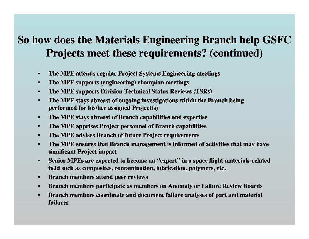
• The MPE attends regular Project Systems Engineering meetings• The MPE supports (engineering) champion meetings• The MPE supports Division Technical Status Reviews (TSRs)• The MPE stays abreast of ongoing investigations within the Branch being
performed for his/her assigned Project(s)
• The MPE stays abreast of Branch capabilities and expertise• The MPE apprises Project personnel of Branch capabilities• The MPE advises Branch of future Project requirements• The MPE ensures that Branch management is informed of activities that may have
significant Project impact• Senior MPEs are expected to become an “expert” in a space flight materials-related
• field such as composites, contamination, lubrication, polymers, etc.• Branch members attend peer reviews• Branch members participate as members on Anomaly or Failure Review Boards• Branch members coordinate and document failure analyses of part and material
failures
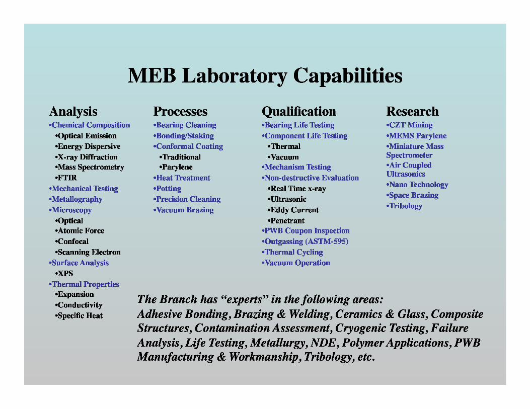
Processes-Bearing Cleaning-Bonding/Staking-Conformal Coating
-Traditional-Parylene
-Heat Treatment-Potting-Precision Cleaning-Vacuum Brazing
Qualification-Bearing Life Testing-Component Life Testing
-Thermal-Vacuum
-Mechanism Testing-Non-destructive Evaluation
-Real Time x-ray-Ultrasonic-Eddy Current-Penetrant
-PWB Coupon Inspection-Outgassing (ASTM-595)-Thermal Cycling-Vacuum Operation
Research-CZT Mining-MEMS Parylene-Miniature MassSpectrometer-Air CoupledUltrasonics-Nano Technology-Space Brazing-Tribology
MEB Laboratory Capabilities
Analysis-Chemical Composition
-Optical Emission-Energy Dispersive-X-ray Diffraction-Mass Spectrometry-FTIR
-Mechanical Testing-Metallography-Microscopy
-Optical-Atomic Force-Confocal-Scanning Electron
• -Surface Analysis-XPS
-Thermal Properties-Expansion-Conductivity-Specific Heat
The Branch has “experts” in the following areas:Adhesive Bonding, Brazing & Welding, Ceramics & Glass, CompositeStructures, Contamination Assessment, Cryogenic Testing, FailureAnalysis, Life Testing, Metallurgy, NDE, Polymer Applications, PWBManufacturing & Workmanship, Tribology, etc.
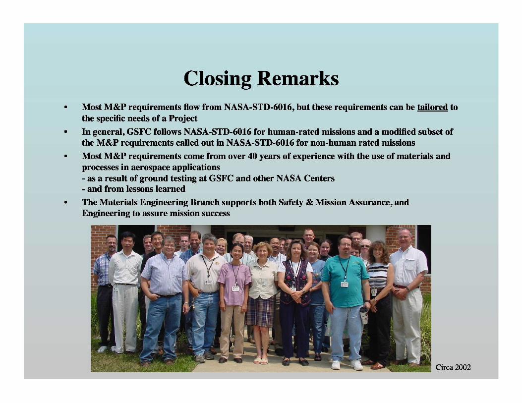
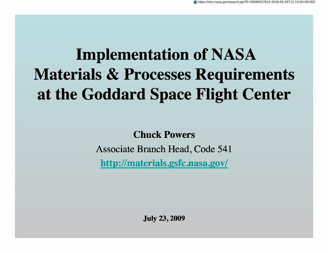
Circa 2002
Closing Remarks• Most M&P requirements flow from NASA-STD-6016, but these requirements can be tailored to
the specific needs of a Project• In general, GSFC follows NASA-STD-6016 for human-rated missions and a modified subset of
the M&P requirements called out in NASA-STD-6016 for non-human rated missions• Most M&P requirements come from over 40 years of experience with the use of materials and
processes in aerospace applications- as a result of ground testing at GSFC and other NASA Centers- and from lessons learned
• The Materials Engineering Branch supports both Safety & Mission Assurance, andEngineering to assure mission success
Backup Slides
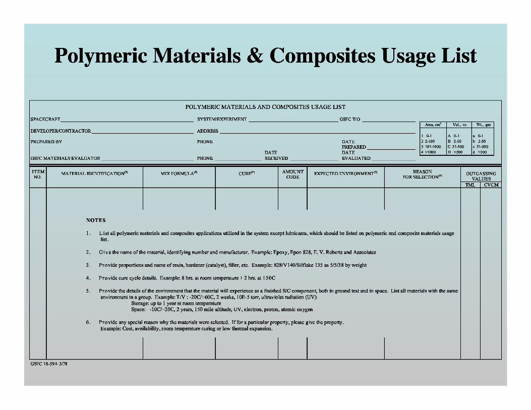
Polymeric Materials & Composites Usage List
POLYMERIC MATERIALS AND COMPOSITES USAGE LIST
SPACECRAFT_______________________________________________________ SYSTEM/EXPERIMENT _____________________________________GSFC T/O
DEVELOPER/CONTRACTOR __________________________________________ ADDRESS __________________________________________________________
PREPARED BY PHONE DATEPREPARED __
DATE
DATEGSFC MATERIALS EVALUATOR ___________ PHONE
RECEIVED
EVALUATED
ITEM MATERIAL IDENTIFICATION (2)
NO.
NOTES
1. List all polymeric materials and composites applications utilized in the system except lubricants, which should be listed on polymeric and composite materials usagelist.
2. Give the name of the material, identifying number and manufacturer. Example: Epoxy, Epon 828, E. V. Roberts and Associates
3. Provide proportions and name of resin, hardener (catalyst), filler, etc. Example: 828/V 140/Silflake 135 as 5/5/38 by weight
4. Provide cure cycle details. Example: 8 hrs. at room temperature + 2 hrs. at 150C
5. Provide the details of the environment that the material will experience as a finished S/C component, both in ground test and in space. List all materials with the sameenvironment in a group. Example: T/V : -20C/+60C, 2 weeks, 10E-5 torr, ultraviolet radiation (UV)
Storage: up to 1 year at room temperatureSpace: -10C/+20C, 2 years, 150 mile altitude, UV, electron, proton, atomic oxygen
6. Provide any special reason why the materials were selected. If for a particular property, please give the property.Example: Cost, availability, room temperature curing or low thermal expansion.
Area, cm2 Vol., cc Wt., gm
1 0-1 A 0-1 a 0-12 2-100 B 2-50 b 2-503 101-1000 C 51-500 c 51-5004 >1000 D >500 d >500
MIX FORMULA (3)CURE (4) AMOUNTEXPECTED ENVIRONMENT() REASON OUTGASSINGCODE FOR SELECTION (6)
VALUES
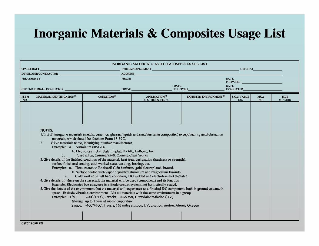
INORGANIC MATERIALS AND COMPOSITES USAGE LISTSPACECRAFT _______________________________________________________ SYSTEM/EXPERIMENT ____________________________________________________________ GSFC T/O ____________________
DEVELOPER/CONTRACTOR __________________________________________ ADDRESS______________________________________________________________________________________________________
PREPARED BY ______________________________________________________ PHONE ________________________________________________________________ DATEPREPARED ____________________________
DATE DATEGSFC MATERIALS EVALUATOR ______________________________________ PHONE ____________________________ RECEIVED _________________________ EVALUATED___________________________
ITEM MATERIAL IDENTIFICATION() CONDITION() APPLICATION() EXPECTED ENVIRONMENTS) S.C.C. TABLE MUA NDENO. OR OTHER SPEC. NO. NO. NO. METHOD
NOTES:1. List all inorganic materials (metals, ceramics, glasses, liquids and metal/ceramic composites) except bearing and lubrication
materials, which should be listed on Form 18-59C.2. G i ve materials name, identifying number manufacturer.
Example: a. Aluminum 6061-T6b. Electroless nickel plate, Enplate Ni 410, Enthone, Inc
c. Fused silica, Corning 7940, Corning Class Works3. Give details of the finished condition of the material, heat-treat designation (hardness or strength),
surface finish and coating, cold worked state, welding, brazing, etc.Example: a. Heat-treated to Rockwell C 60 hardness, gold electroplated, brazed.
b. Surface coated with vapor deposited aluminum and magnesium fluoridec . C old worked to full hare condition, TIG welded and electroless nickel-plated.
4. Give details of where on the spacecraft the material will be used (component) and its function.Example: Electronics box structure in attitude control system, not hermetically sealed.
5. Give the details of the environment that the material will experience as a finished S/C component, both in ground test and inspace. Exclude vibration environment. List all materials with the same environment in a group.Example: T/V: -20C/+60C, 2 weeks, 10E-5 torr, Ultraviolet radiation (UV)
Storage: up to 1 year at room temperatureSpace: -10C/+20C, 2 years, 150 miles altitude, UV, electron, proton, Atomic Oxygen
Inorganic Materials & Composites Usage List
GSFC 18-59B 3/78
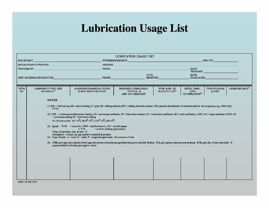
Lubrication Usage List
LUBRICATION USAGE LIST
SPACECRAFT _______________________________________________________ SYSTEM/EXPERIMENT ____________________________________________________________ GSFC T/O ____________________
DEVELOPED/CONTRACTOR __________________________________________ ADDRESS______________________________________________________________________________________________________
PREPARED BY ______________________________________________________ PHONE ________________________________________________________________ DATEPREPARED ____________________________
DATE DATEGSFC MATERIALS EVALUATOR_______________________________________ PHONE ____________________________ RECEIVED _________________________ EVALUATED___________________________
ITEM COMPONENT TYPE, SIZE COMPONENT MANUFACTURER PROPOSED LUBRICATION TYPE & NO. OF SPEED, TEMP., TYPE OF LOADS OTHER DETAILS (5)
NO. MATERIAL (1) & MFR. IDENTIFICATION SYSTEM & WEAR CYCLES(2) ATM. & AMT.AMT. OF LUBRICANT OF OPERATION (3)
NOTES
(1) BB = ball bearing, SB = sleeve bearing, G = gear, SS = sliding surfaces, SEC = sliding electrical contacts. Give generic identification of materials used for the component, e.g., 440C steel,PTFE.
(2) CUR = continuous unidirectional rotation, CO = continuous oscillation, IR = intermittent rotation, IO = intermittent oscillation, SO = small oscillation, (<30°), LO = large oscillation (>30°), CS= continuous sliding, IS = intermittent sliding.No. of wear cycles: A(1-102), B(102-104), C(104-106), D(>106)
(3) Speed: RPM = revs./min., OPM = oscillations/min., VS = variable speedC P M = cm/min. (sliding applications)
Temp. of operation, max. & min., °CAtmosphere: vacuum, air, gas, sealed or unsealed & pressure
(4) Type of loads: A = axial, R = radial, T = tangential (gear load). Give amount of load.
(5) If BB, give type and material of ball cage and number of shields and specified ball groove and ball finishes. If G, give surface treatment and hardness. If SB, give dia. of bore and width. Iftorque available is limited, give approx. value.
GSFC 18-59C 3/78
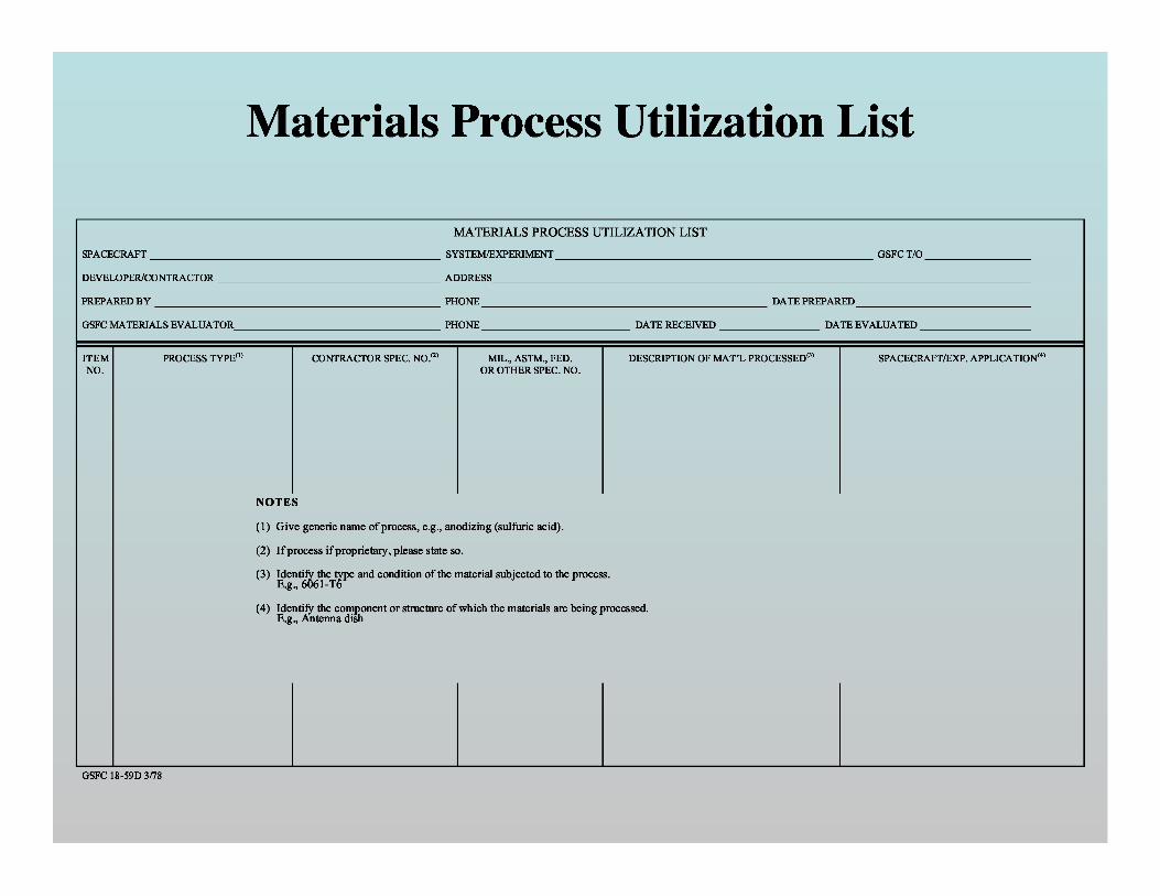
Materials Process Utilization List
MATERIALS PROCESS UTILIZATION LIST
SPACECRAFT _______________________________________________________ SYSTEM/EXPERIMENT ____________________________________________________________ GSFC T/O ____________________
DEVELOPER/CONTRACTOR __________________________________________ ADDRESS______________________________________________________________________________________________________
PREPARED BY ______________________________________________________ PHONE ______________________________________________________ DATE PREPARED _________________________________
GSFC MATERIALS EVALUATOR_______________________________________ PHONE ____________________________ DATE RECEIVED ___________________ DATE EVALUATED _____________________
ITEM PROCESS TYPE (1) CONTRACTOR SPEC. NO. (2)MIL., ASTM., FED. DESCRIPTION OF MAT’L PROCESSED(3)SPACECRAFT/EXP. APPLICATION (4)
NO. OR OTHER SPEC. NO.
NOTES
(1) Give generic name of process, e.g., anodizing (sulfuric acid).
(2) If process if proprietary, please state so.
(3) Identify the e and condition of the material subjected to the process.E.g., 6061-Ttyp
(4) Identify the component or structure of which the materials are being processed.E.g., Antenna dish
GSFC 18-59D 3/78
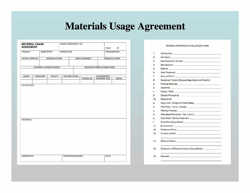
Materials Usage Agreement
0.0 10 0
-2.0 10 4
• -4.0 104
.y
n
• -6.0 104
m
N• -8.0 104
• -1.0 10 5
• -1.2 10 5
-3000 -2500 -2000 -1500 -1000 -500 0
Strain (m)
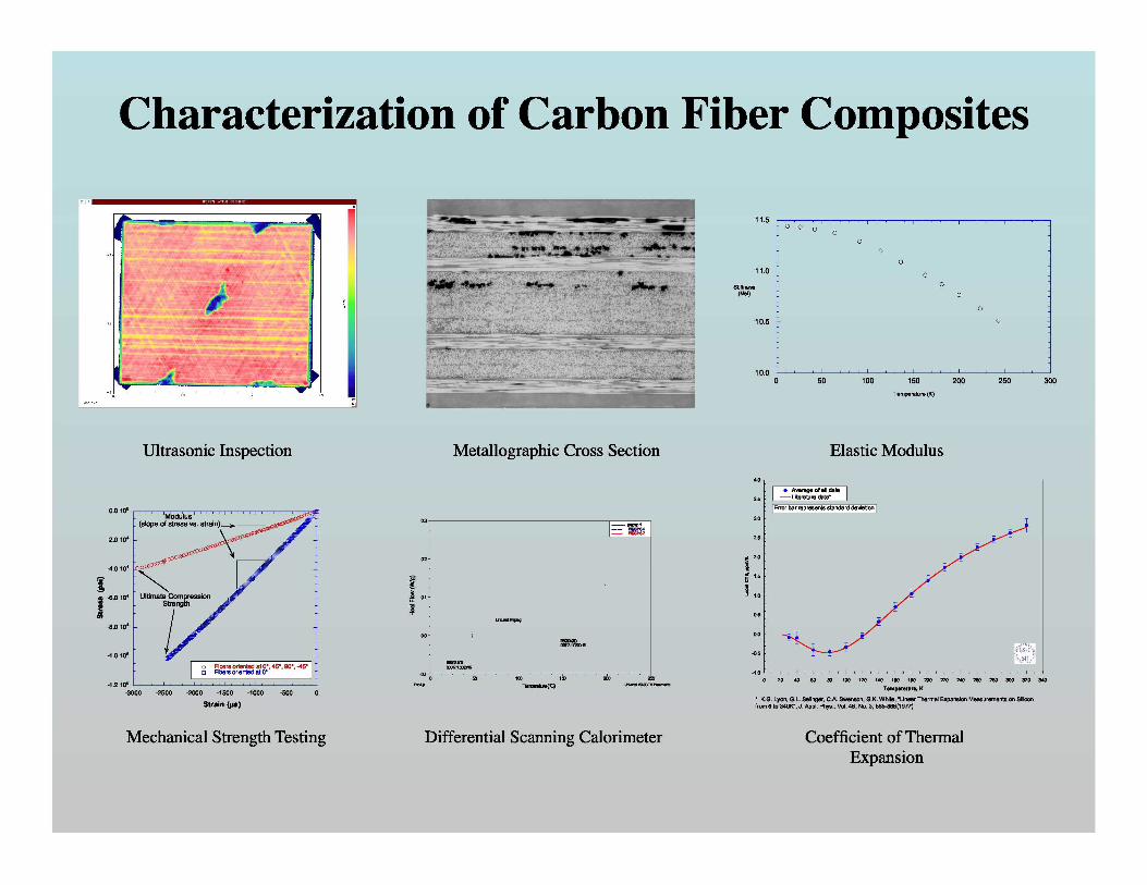
Mechanical Strength Testing
Metallographic Cross Section
Exo Up Terperature (¡C)
Universal V3.6C TA Instrurents
Differential Scanning Calorimeter
Ultrasonic Inspection
Characterization of Carbon Fiber Composites
11.5 0 0 00
00
011.0 0
Stiffness 0(Msi) 0
0
10.5 0
10.00 50 100 150 200 250 300
Temperature (It)
Elastic ModulusAverage of all data
4.0 e
• Average of all tlata
3.5 Literature tlata'
Error bar represents stantlartl tleviation
3.0
2.5
2.0
+G 1.5
s 1.0
0.5
0.0
-0.5 GSF ^
5J _:
-1.00 20 40 60 80 100 120 140 160 180200 220 240 260 280 300 320 340
Temperature, K
' I.G. Lyon, G.L. Salinger, C.A. Swenson, G.I. White, "Linear Thermal Expansion Measurements on Siliconfrom 6 to 340I", J. Appl. Phys., Vol. 48, No. 3, 865-868(1977)
Coefficient of ThermalExpansion