Embed Size (px)
Citation preview
Implementation of a Sensorless SpeedControlled Brushless DC drive using
TMS320F240
Literature Number: BPRA072Texas Instruments Europe
November 1997

IMPORTANT NOTICE
Texas Instruments (TI) reserves the right to make changes to its products or to discontinue anysemiconductor product or service without notice, and advises its customers to obtain the latestversion of relevant information to verify, before placing orders, that the information being reliedon is current.
TI warrants performance of its semiconductor products and related software to thespecifications applicable at the time of sale in accordance with TI's standard warranty. Testingand other quality control techniques are utilized to the extent TI deems necessary to support thiswarranty. Specific testing of all parameters of each device is not necessarily performed, exceptthose mandated by government requirements.
Certain applications using semiconductor products may involve potential risks of death,personal injury, or severe property or environmental damage ("Critical Applications").
TI SEMICONDUCTOR PRODUCTS ARE NOT DESIGNED, INTENDED, AUTHORIZED, ORWARRANTED TO BE SUITABLE FOR USE IN LIFE-SUPPORT APPLICATIONS, DEVICESOR SYSTEMS OR OTHER CRITICAL APPLICATIONS.
Inclusion of TI products in such applications is understood to be fully at the risk of the customer.Use of TI products in such applications requires the written approval of an appropriate TI officer.Questions concerning potential risk applications should be directed to TI through a local SCsales office.
In order to minimize risks associated with the customer's applications, adequate design andoperating safeguards should be provided by the customer to minimize inherent or proceduralhazards.
TI assumes no liability for applications assistance, customer product design, softwareperformance, or infringement of patents or services described herein. Nor does TI warrant orrepresent that any license, either express or implied, is granted under any patent right,copyright, mask work right, or other intellectual property right of TI covering or relating to anycombination, machine, or process in which such semiconductor products or services might be orare used.
Copyright 1997, Texas Instruments Incorporated
Contents
Implementation of a Sensorless Speed Controlled Brushless DC drive using TMS320F240 iii
Contents
1. Introduction.............................................................................................................. 1
2. Sensorless Brushless DC Drive Presentation.......................................................... 12.1 The motor ..................................................................................................... 12.2 The control hardware.................................................................................... 12.3 The Power Electronics Hardware ................................................................. 2
2.3.1 The Power Conversion Dedicated Hardware .............................. 22.3.2 The Sensorless Dedicated Hardware .......................................... 3
2.4 The control algorithm .................................................................................... 4
3. Sensorless Principles .............................................................................................. 43.1 Theoretical Background................................................................................ 53.2 Practical Point of View .................................................................................. 6
3.2.1 Neutral Point Voltage Computation ............................................. 63.2.2 Bemf Zero Crossing Point Computation ...................................... 83.2.3 Electrical Behaviour at Commutation Points................................ 83.2.4 Some Bemf Zero Crossing Results ............................................. 93.2.5 Commutation Instants Computation .......................................... 103.2.6 Self Correction of Phase Use Imbalance................................... 113.2.7 Startup Procedure ..................................................................... 13
4. Software Organization ........................................................................................... 154.1 DSP Controller Setup ................................................................................. 154.2 Software Variables Initialization .................................................................. 16
4.2.1 Bemf Scanning function variables ............................................. 164.2.2 Commutation Algorithm Variables ............................................. 174.2.3 Rotor Magnetic Stall Variables .................................................. 174.2.4 Current Loop Variables.............................................................. 174.2.5 Speed Loop Variables ............................................................... 18
4.3 Interrupts Flow Charts................................................................................. 184.3.1 PWM Unit Interrupt Flowchart ................................................... 184.3.2 ADC Unit Interrupt Flowchart..................................................... 20
4.4 SEQUENCE Function Flow Chart............................................................... 21
5. Summary ............................................................................................................... 22
References ................................................................................................................ 23
Appendix A Sensorless BLDC Drive Control Assembly Code .................................. 24
Appendix B Linker File.............................................................................................. 37
Contents
Implementation of a Sensorless Speed Controlled Brushless DC drive using TMS320F240 iv
List of Figures
Figure 1: Top View of TMS320F240 EVM Board .............................................................. 2
Figure 2: Power Electronics Topology .............................................................................. 3
Figure 3: Basic Sensorless Additional Hardware .............................................................. 4
Figure 4: Stator Terminal Electrical Model ........................................................................ 5
Figure 5: Bemf Wave-form Shapes................................................................................... 6
Figure 6: PWM Strategy and Operating System ............................................................... 8
Figure 7: Zero Crossing Results at Different Running Speeds.......................................... 9
Figure 8: Computed Commutation Instants vs Hall Effect Sensor Outputs..................... 11
Figure 9: Balanced and Unbalanced Phase Use ............................................................ 12
Figure 10: Phase Use Imbalance Correction Module...................................................... 12
Figure 11: Phase Use without and with Imbalance Corrector ......................................... 13
Figure 12: Global Structure of the Sensorless Control Code .......................................... 15
Figure 13: PWM Interrupt Flowchart ............................................................................... 19
Figure 14: ADC Interrupt Flowchart ................................................................................ 20
Figure 15: SEQUENCE Function Flowchart.................................................................... 21
Implementation of a Sensorless Speed Controlled Brushless DC drive using TMS320F240 1
Implementation of a Sensorless Speed Controlled Brushless DCDrive using the TMS320F240
ABSTRACT
The DSP Controller TMS320F240 from Texas Instruments is suitable for awide range of motor drives. TMS320F240 provides a single chip solution byintegrating on-chip not only a high computational power but also all theperipherals necessary for electric motor control. The present applicationnote describes how a sensorless, speed controlled, brushless DC drive canbe implemented using TMS320F240. This document shows that thissensorless solution is single chip and really cost effective in comparison withthe sensored solution.
1. IntroductionControlling a synchronous permanent magnet trapezoidal Bemf shape motor by directcurrent results in a simple low cost drive with a high mechanical power density. In orderto reduce the system cost, it is desirable to eliminate the rotor position sensor used tooperate the Brushless Direct Current (BLDC) motor. This document describes a methodfor commutation of a BLDC motor requiring no rotor position sensor and suppressing theposition sensor cost at no cost other than software. The control described here operatesin closed loop from zero speed. The initial rotor position is fixed by energizing one,arbitrarily selected phase. This application report covers the TMS320F240 DSPController, provides the sensorless control DSP Controller software and demonstratessome really effective benefits.
2. Sensorless Brushless DC Drive Presentation
2.1 The motor
The synchronous machine with permanent magnets used in this application note is athree-phase Y-connected motor. It has one magnetic non-salient pole pair on the rotor.The thooless stator is made of ironless windings. The stator phase inductance is0.045mH (measured at 1kHz) and the phase resistance is 300mΩ. The maximumpermissible current at 5000rpm is 2.9A and the torque constant is equal to 11.8mNm/A. Itis assumed to have trapezoidal back electromotive force (Bemf) wave form shapes and issupplied with direct current. The DC bus voltage is 18V.
2.2 The control hardware
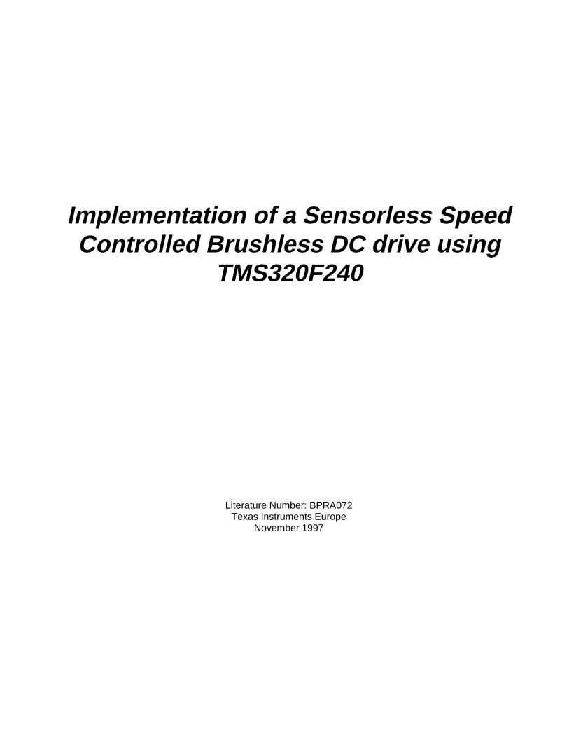
The control hardware can be either the TMS320F240 Evaluation Module introduced byTexas Instruments or the MCK240 developed by Portescap/Technosoft. In this
Implementation of a Sensorless Speed Controlled Brushless DC drive using TMS320F240 2
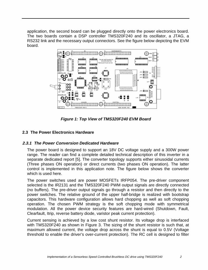
application, the second board can be plugged directly onto the power electronics board.The two boards contain a DSP controller TMS320F240 and its oscillator, a JTAG, aRS232 link and the necessary output connectors. See the figure below depicting the EVMboard.
Figure 1: Top View of TMS320F240 EVM Board
2.3 The Power Electronics Hardware
2.3.1 The Power Conversion Dedicated Hardware
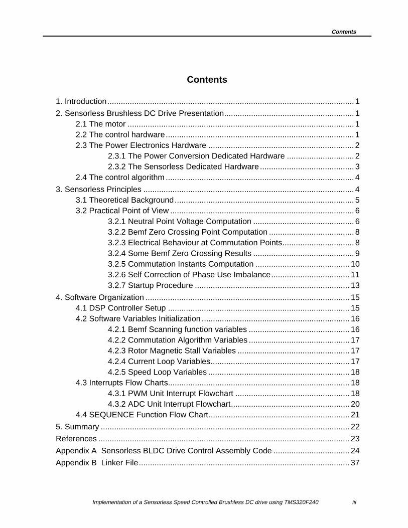
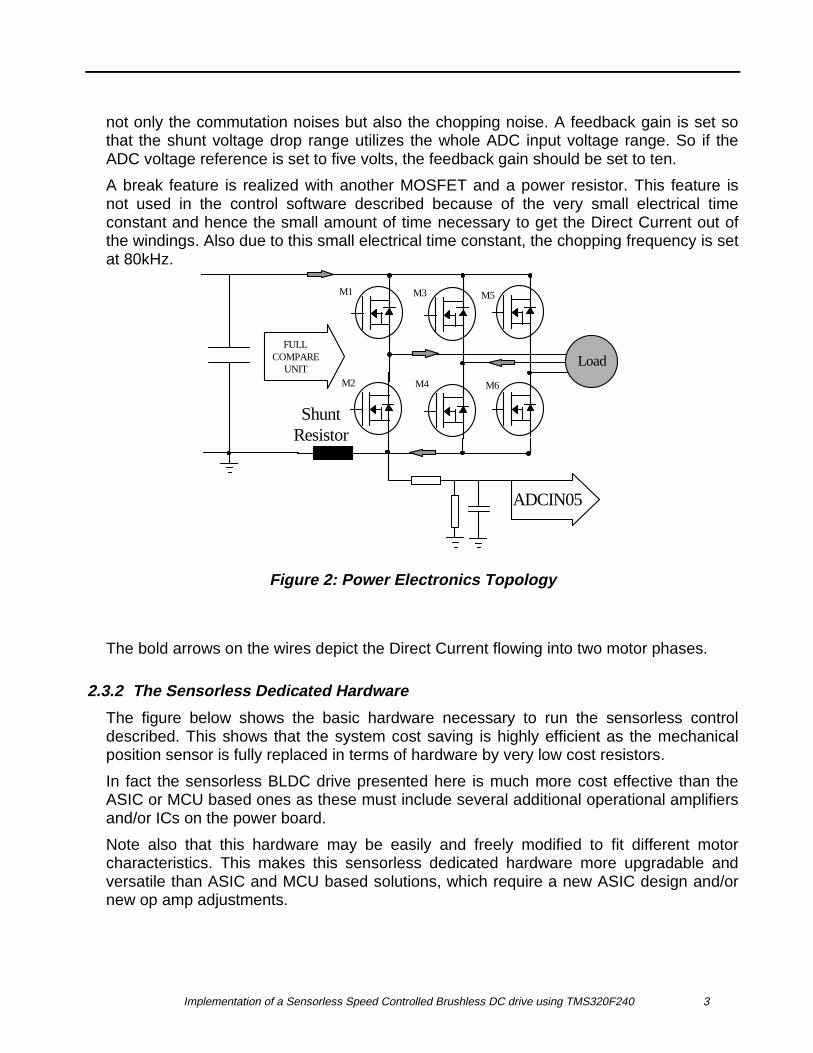
The power board is designed to support an 18V DC voltage supply and a 300W powerrange. The reader can find a complete detailed technical description of this inverter in aseparate dedicated report [5]. The converter topology supports either sinusoidal currents(Three phases ON operation) or direct currents (two phases ON operation). The lattercontrol is implemented in this application note. The figure below shows the converterwhich is used here.
The power switches used are power MOSFETs IRFP054. The pre-driver componentselected is the IR2131 and the TMS320F240 PWM output signals are directly connected(no buffers). The pre-driver output signals go through a resistor and then directly to thepower switches. The relative ground of the upper half-bridge is realized with bootstrapcapacitors. This hardware configuration allows hard chopping as well as soft choppingoperation. The chosen PWM strategy is the soft chopping mode with symmetricalmodulation. All the power device security features are hard-wired (Shutdown, Fault,Clearfault, Itrip, reverse battery diode, varistor peak current protection).
Current sensing is achieved by a low cost shunt resistor. Its voltage drop is interfacedwith TMS320F240 as shown in Figure 3. The sizing of the shunt resistor is such that, atmaximum allowed current, the voltage drop across the shunt is equal to 0.5V (Voltagethreshold to enable the driver’s over-current protection). The RC cell is designed to filter
Implementation of a Sensorless Speed Controlled Brushless DC drive using TMS320F240 3
not only the commutation noises but also the chopping noise. A feedback gain is set sothat the shunt voltage drop range utilizes the whole ADC input voltage range. So if theADC voltage reference is set to five volts, the feedback gain should be set to ten.
A break feature is realized with another MOSFET and a power resistor. This feature isnot used in the control software described because of the very small electrical timeconstant and hence the small amount of time necessary to get the Direct Current out ofthe windings. Also due to this small electrical time constant, the chopping frequency is setat 80kHz.
ShuntResistor
Load
M1
M2
M3
M4
M5
M6
FULLCOMPARE
UNIT
ADCIN05
Figure 2: Power Electronics Topology
The bold arrows on the wires depict the Direct Current flowing into two motor phases.
2.3.2 The Sensorless Dedicated Hardware
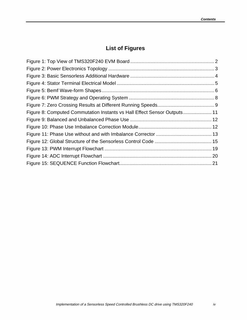
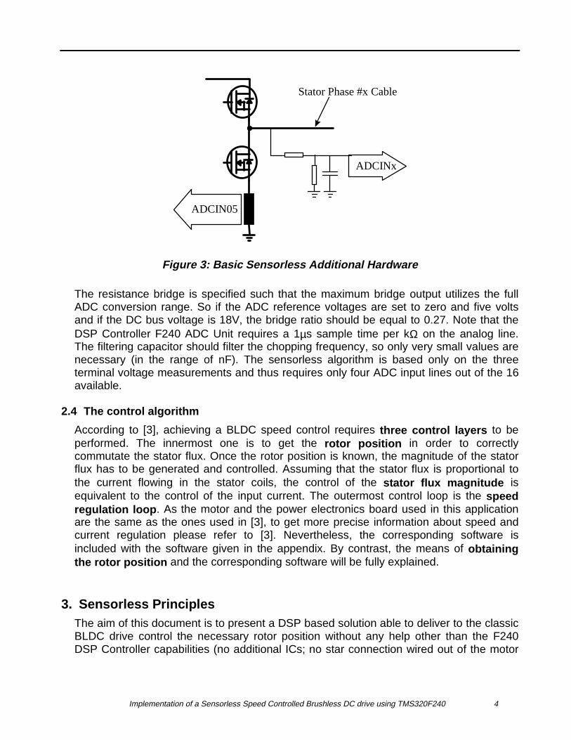
The figure below shows the basic hardware necessary to run the sensorless controldescribed. This shows that the system cost saving is highly efficient as the mechanicalposition sensor is fully replaced in terms of hardware by very low cost resistors.
In fact the sensorless BLDC drive presented here is much more cost effective than theASIC or MCU based ones as these must include several additional operational amplifiersand/or ICs on the power board.
Note also that this hardware may be easily and freely modified to fit different motorcharacteristics. This makes this sensorless dedicated hardware more upgradable andversatile than ASIC and MCU based solutions, which require a new ASIC design and/ornew op amp adjustments.
Implementation of a Sensorless Speed Controlled Brushless DC drive using TMS320F240 4
ADCINx
ADCIN05
Stator Phase #x Cable
Figure 3: Basic Sensorless Additional Hardware
The resistance bridge is specified such that the maximum bridge output utilizes the fullADC conversion range. So if the ADC reference voltages are set to zero and five voltsand if the DC bus voltage is 18V, the bridge ratio should be equal to 0.27. Note that theDSP Controller F240 ADC Unit requires a 1µs sample time per kΩ on the analog line.The filtering capacitor should filter the chopping frequency, so only very small values arenecessary (in the range of nF). The sensorless algorithm is based only on the threeterminal voltage measurements and thus requires only four ADC input lines out of the 16available.
2.4 The control algorithm
According to [3], achieving a BLDC speed control requires three control layers to beperformed. The innermost one is to get the rotor position in order to correctlycommutate the stator flux. Once the rotor position is known, the magnitude of the statorflux has to be generated and controlled. Assuming that the stator flux is proportional tothe current flowing in the stator coils, the control of the stator flux magnitude isequivalent to the control of the input current. The outermost control loop is the speedregulation loop . As the motor and the power electronics board used in this applicationare the same as the ones used in [3], to get more precise information about speed andcurrent regulation please refer to [3]. Nevertheless, the corresponding software isincluded with the software given in the appendix. By contrast, the means of obtainingthe rotor position and the corresponding software will be fully explained.
3. Sensorless PrinciplesThe aim of this document is to present a DSP based solution able to deliver to the classicBLDC drive control the necessary rotor position without any help other than the F240DSP Controller capabilities (no additional ICs; no star connection wired out of the motor
Implementation of a Sensorless Speed Controlled Brushless DC drive using TMS320F240 5
housing). The following description gives a succinct theoretical background and coversevery practical aspect.
3.1 Theoretical Background
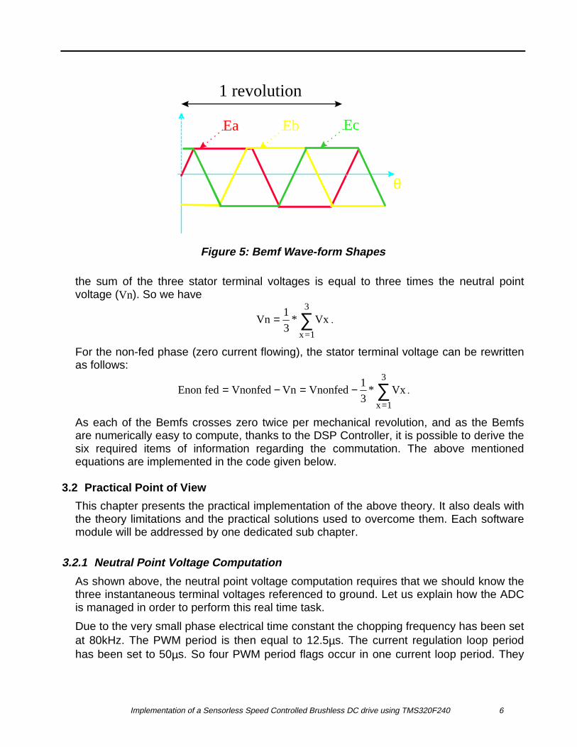
According to [4] in the sensored control structure, the phases are commutated onceevery 60º mechanical rotation of the rotor. This implies that only six commutation signalsare sufficient to drive a BLDC motor. Furthermore, an efficient control implies asynchronization between the phase Bemf and the phase supply so that the Bemf crosseszero once during the non-fed 60º sector. The next paragraph shows how it is possible toget the three Bemfs and their zero crossings.
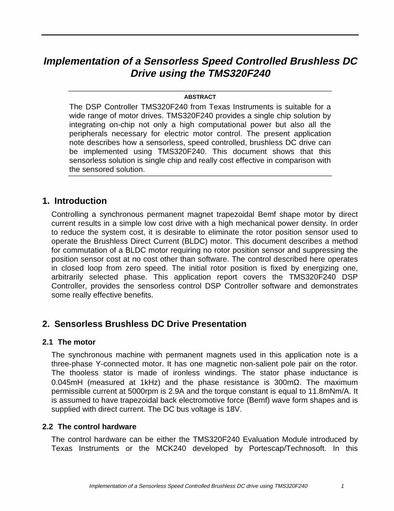
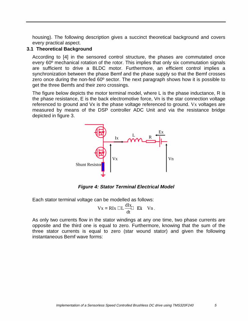
The figure below depicts the motor terminal model, where L is the phase inductance, R isthe phase resistance, E is the back electromotive force, Vn is the star connection voltagereferenced to ground and Vx is the phase voltage referenced to ground. Vx voltages aremeasured by means of the DSP controller ADC Unit and via the resistance bridgedepicted in figure 3.
Shunt Resistor
ExIx
VnVx
L R
Figure 4: Stator Terminal Electrical Model
Each stator terminal voltage can be modelled as follows:
Vx RIx LdIx
dtEx Vn= + + + .
As only two currents flow in the stator windings at any one time, two phase currents areopposite and the third one is equal to zero. Furthermore, knowing that the sum of thethree stator currents is equal to zero (star wound stator) and given the followinginstantaneous Bemf wave forms:
Implementation of a Sensorless Speed Controlled Brushless DC drive using TMS320F240 6
θ
1 revolution
Ea Eb Ec
Figure 5: Bemf Wave-form Shapes
the sum of the three stator terminal voltages is equal to three times the neutral pointvoltage (Vn). So we have
Vn Vxx=1
3
= ∑1
3* .
For the non-fed phase (zero current flowing), the stator terminal voltage can be rewrittenas follows:
Enon fed Vnonfed Vn Vnonfed Vxx=1
3
= − = − ∑1
3* .
As each of the Bemfs crosses zero twice per mechanical revolution, and as the Bemfsare numerically easy to compute, thanks to the DSP Controller, it is possible to derive thesix required items of information regarding the commutation. The above mentionedequations are implemented in the code given below.
3.2 Practical Point of View
This chapter presents the practical implementation of the above theory. It also deals withthe theory limitations and the practical solutions used to overcome them. Each softwaremodule will be addressed by one dedicated sub chapter.
3.2.1 Neutral Point Voltage Computation
As shown above, the neutral point voltage computation requires that we should know thethree instantaneous terminal voltages referenced to ground. Let us explain how the ADCis managed in order to perform this real time task.
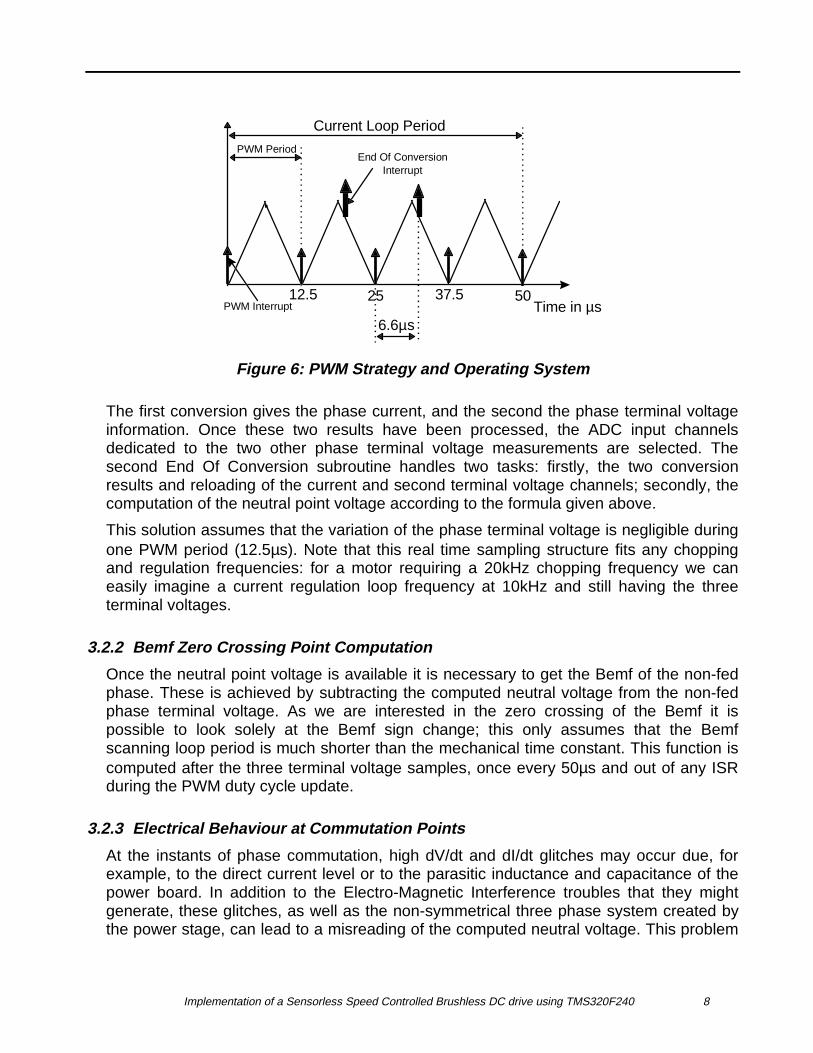
Due to the very small phase electrical time constant the chopping frequency has been setat 80kHz. The PWM period is then equal to 12.5µs. The current regulation loop periodhas been set to 50µs. So four PWM period flags occur in one current loop period. They

Implementation of a Sensorless Speed Controlled Brushless DC drive using TMS320F240 7
are all acknowledged by the DSP Controller Core and the corresponding interruptsubroutine is initiated. Only when the current PWM period ISR is the first or the second(among the four available during one current control loop) is a conversion is started bysoftware. At the End Of Conversion an interrupt to the core is requested, acknowledgedand initiates processing of the two results. The following plot depicts the organization ofthe interrupts.
Implementation of a Sensorless Speed Controlled Brushless DC drive using TMS320F240 8
50Time in µs
12.5 25 37.5
Current Loop Period
PWM Period
6.6µs
End Of ConversionInterrupt
PWM Interrupt
Figure 6: PWM Strategy and Operating System
The first conversion gives the phase current, and the second the phase terminal voltageinformation. Once these two results have been processed, the ADC input channelsdedicated to the two other phase terminal voltage measurements are selected. Thesecond End Of Conversion subroutine handles two tasks: firstly, the two conversionresults and reloading of the current and second terminal voltage channels; secondly, thecomputation of the neutral point voltage according to the formula given above.
This solution assumes that the variation of the phase terminal voltage is negligible duringone PWM period (12.5µs). Note that this real time sampling structure fits any choppingand regulation frequencies: for a motor requiring a 20kHz chopping frequency we caneasily imagine a current regulation loop frequency at 10kHz and still having the threeterminal voltages.
3.2.2 Bemf Zero Crossing Point Computation
Once the neutral point voltage is available it is necessary to get the Bemf of the non-fedphase. These is achieved by subtracting the computed neutral voltage from the non-fedphase terminal voltage. As we are interested in the zero crossing of the Bemf it ispossible to look solely at the Bemf sign change; this only assumes that the Bemfscanning loop period is much shorter than the mechanical time constant. This function iscomputed after the three terminal voltage samples, once every 50µs and out of any ISRduring the PWM duty cycle update.
3.2.3 Electrical Behaviour at Commutation Points
At the instants of phase commutation, high dV/dt and dI/dt glitches may occur due, forexample, to the direct current level or to the parasitic inductance and capacitance of thepower board. In addition to the Electro-Magnetic Interference troubles that they mightgenerate, these glitches, as well as the non-symmetrical three phase system created bythe power stage, can lead to a misreading of the computed neutral voltage. This problem
Implementation of a Sensorless Speed Controlled Brushless DC drive using TMS320F240 9
is solved by discarding the first scans of the Bemf once a new phase commutationoccurs. The discard duration is fully customizable as this is a software module. Theduration depends on the power switches, the power board design, the phase inductanceand the driven direct current. This parameter is system-dependent and should be set to alarge value in the early development stages. Later on it is possible to tune to a very smalldiscard duration in order to achieve a better control.
3.2.4 Some Bemf Zero Crossing Results
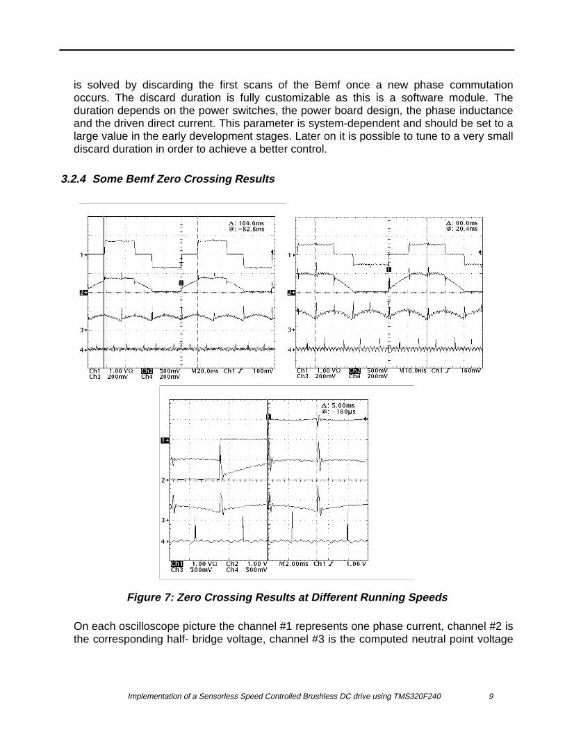
Figure 7: Zero Crossing Results at Different Running Speeds
On each oscilloscope picture the channel #1 represents one phase current, channel #2 isthe corresponding half- bridge voltage, channel #3 is the computed neutral point voltage
Implementation of a Sensorless Speed Controlled Brushless DC drive using TMS320F240 10
and the channel #4 gives one peak each time the software detects the zero crossing ofthe scanned Bemf. The different speeds tested here are respectively 600, 1000 and2000rpm. The Bemf zero crossing algorithm has been successfully tested down to30rpm. The most interesting information is given by the neutral voltage computation:even if there are very high commutation glitches and/or measurement noises thesoftware recognizes them as glitches thus making it possible to detect the right Bemf signchange. This is achievable because of the high frequency of neutral point voltagecomputation loop. This high frequency can be reached thanks to the autonomous ADCperipheral and to the high DSP Controller CPU power. The channel #4 spikes(representing the Bemf zero crossing) find themselves in the middle of the non-fedsector. This synchronization between the Bemf and the 60º sector is the main result toachieve in order to get the highest motor performance.
3.2.5 Commutation Instants Computation
In an efficient sensored control the Bemf zero crossing events are displaced 30º from theinstants of phase commutation. So before running the sensorless BLDC motor with helpof the six zero crossing events it is necessary to compute the 30º shift of commutationpoints. In fact, depending on the different desired speed ranges, the angle shift might beto any angle. So a position interpolation function should be realized. In this controlsoftware it is implemented as follows: let T be the time that the rotor spent to completethe previous revolution and α be the desired shift angle. By dividing α by 360º andmultiplying the result by T we obtain the amount of time (let us call it ‘shift time’) to bespent before commutating the next phase pair.
A question might be asked regarding the transient response of the system. Let us,therefore, assume that the motor slows down and see how the control reacts. Thecomputed shift time will be too short in comparison with the actual shift time necessary;this early arrival of the commutation point will tend to accelerate the motor. There will bean opposite controller reaction if the motor accelerates. So a kind of natural robustness,arising from the control algorithm, is added to the speed control loop.
In spite of this advantage this shift time solution assumes that the motor speed variationbetween two revolutions is not too critical in comparison with the system dynamicbehaviour.
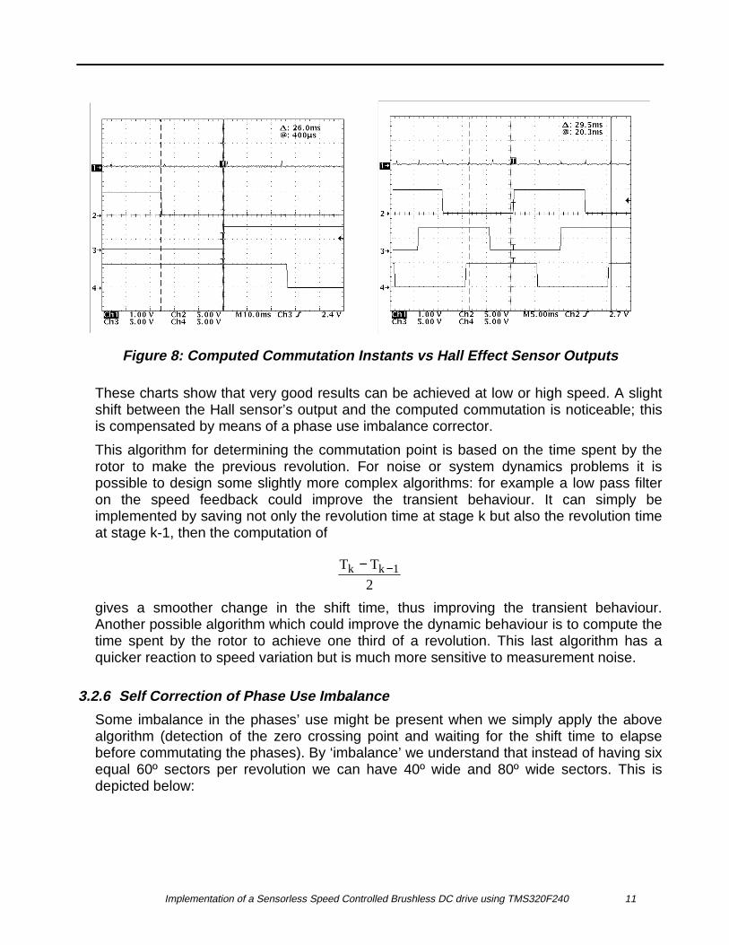
In the software described, α is fixed to 30º. We can imagine an additional softwarefunction giving the shift angle as output and taking the mechanical speed as input. Twocharts are presented below which show the computation of the commutation point incomparison with the three Hall effect sensor outputs. Channel #1 spikes represent thecomputed commutation points, channel #2, 3, 4 represent the Hall sensor output. The leftchart shows results at low speed (380rpm) and the right chart the results at high speed(2030 rpm).
Implementation of a Sensorless Speed Controlled Brushless DC drive using TMS320F240 11
Figure 8: Computed Commutation Instants vs Hall Effect Sensor Outputs
These charts show that very good results can be achieved at low or high speed. A slightshift between the Hall sensor’s output and the computed commutation is noticeable; thisis compensated by means of a phase use imbalance corrector.
This algorithm for determining the commutation point is based on the time spent by therotor to make the previous revolution. For noise or system dynamics problems it ispossible to design some slightly more complex algorithms: for example a low pass filteron the speed feedback could improve the transient behaviour. It can simply beimplemented by saving not only the revolution time at stage k but also the revolution timeat stage k-1, then the computation of
T T
2k k 1− −
gives a smoother change in the shift time, thus improving the transient behaviour.Another possible algorithm which could improve the dynamic behaviour is to compute thetime spent by the rotor to achieve one third of a revolution. This last algorithm has aquicker reaction to speed variation but is much more sensitive to measurement noise.
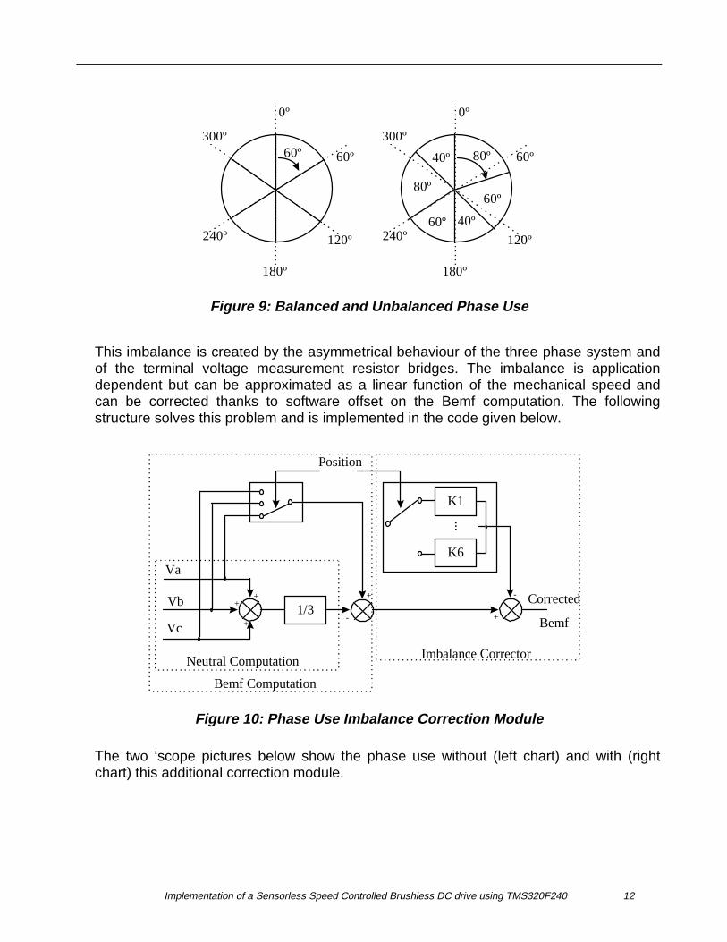
3.2.6 Self Correction of Phase Use Imbalance
Some imbalance in the phases’ use might be present when we simply apply the abovealgorithm (detection of the zero crossing point and waiting for the shift time to elapsebefore commutating the phases). By ‘imbalance’ we understand that instead of having sixequal 60º sectors per revolution we can have 40º wide and 80º wide sectors. This isdepicted below:
Implementation of a Sensorless Speed Controlled Brushless DC drive using TMS320F240 12
60º
0º
60º
120º
180º
240º
300º
0º
60º
120º
180º
240º
300º
80º
60º
40º60º
40º
80º
Figure 9: Balanced and Unbalanced Phase Use
This imbalance is created by the asymmetrical behaviour of the three phase system andof the terminal voltage measurement resistor bridges. The imbalance is applicationdependent but can be approximated as a linear function of the mechanical speed andcan be corrected thanks to software offset on the Bemf computation. The followingstructure solves this problem and is implemented in the code given below.
Corrected
Bemf
Va
Vb
Vc1/3
++
+
Position
-
+
K1
K6
...
+
-
Neutral Computation
Bemf Computation
Imbalance Corrector
Figure 10: Phase Use Imbalance Correction Module
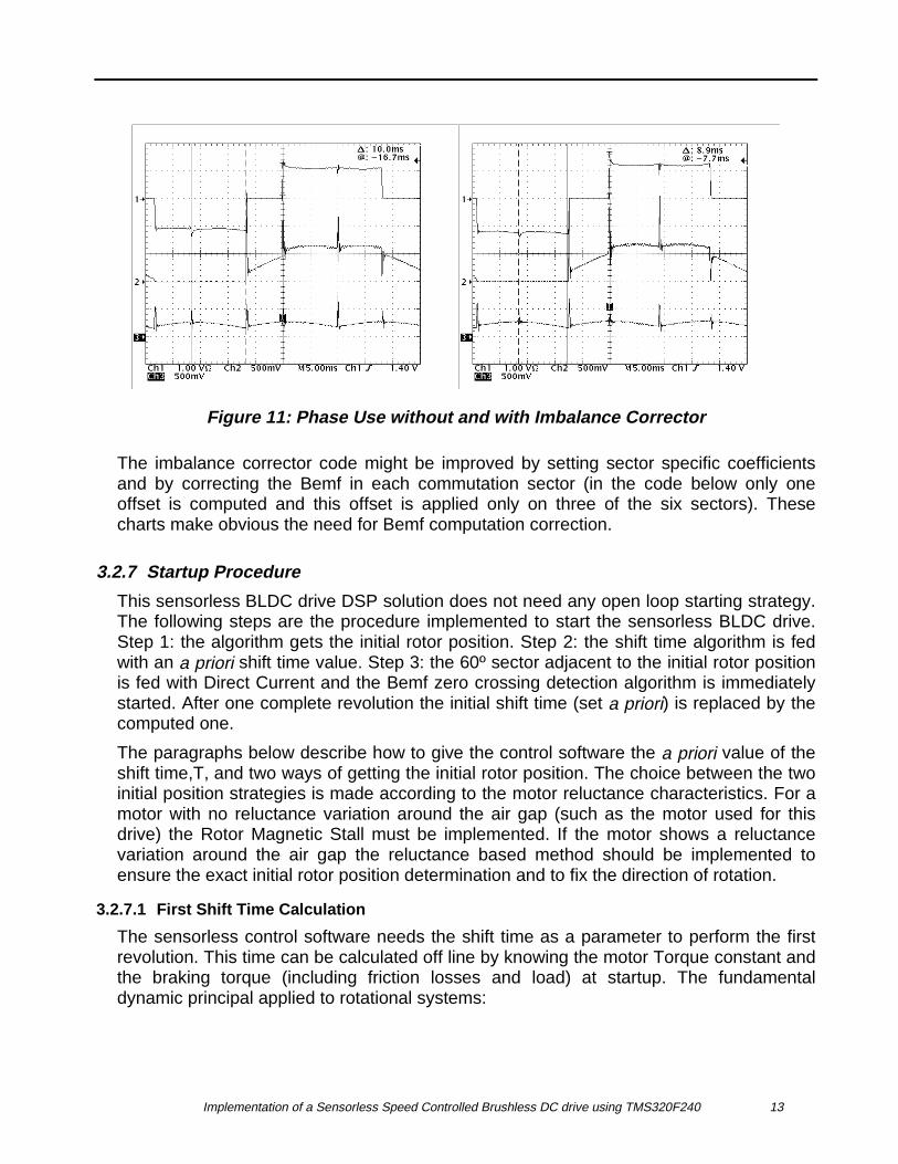
The two ‘scope pictures below show the phase use without (left chart) and with (rightchart) this additional correction module.
Implementation of a Sensorless Speed Controlled Brushless DC drive using TMS320F240 13
Figure 11: Phase Use without and with Imbalance Corrector
The imbalance corrector code might be improved by setting sector specific coefficientsand by correcting the Bemf in each commutation sector (in the code below only oneoffset is computed and this offset is applied only on three of the six sectors). Thesecharts make obvious the need for Bemf computation correction.
3.2.7 Startup Procedure
This sensorless BLDC drive DSP solution does not need any open loop starting strategy.The following steps are the procedure implemented to start the sensorless BLDC drive.Step 1: the algorithm gets the initial rotor position. Step 2: the shift time algorithm is fedwith an a priori shift time value. Step 3: the 60º sector adjacent to the initial rotor positionis fed with Direct Current and the Bemf zero crossing detection algorithm is immediatelystarted. After one complete revolution the initial shift time (set a priori) is replaced by thecomputed one.
The paragraphs below describe how to give the control software the a priori value of theshift time,T, and two ways of getting the initial rotor position. The choice between the twoinitial position strategies is made according to the motor reluctance characteristics. For amotor with no reluctance variation around the air gap (such as the motor used for thisdrive) the Rotor Magnetic Stall must be implemented. If the motor shows a reluctancevariation around the air gap the reluctance based method should be implemented toensure the exact initial rotor position determination and to fix the direction of rotation.
3.2.7.1 First Shift Time Calculation
The sensorless control software needs the shift time as a parameter to perform the firstrevolution. This time can be calculated off line by knowing the motor Torque constant andthe braking torque (including friction losses and load) at startup. The fundamentaldynamic principal applied to rotational systems:
Implementation of a Sensorless Speed Controlled Brushless DC drive using TMS320F240 14
Jd
dtTi
2
2i
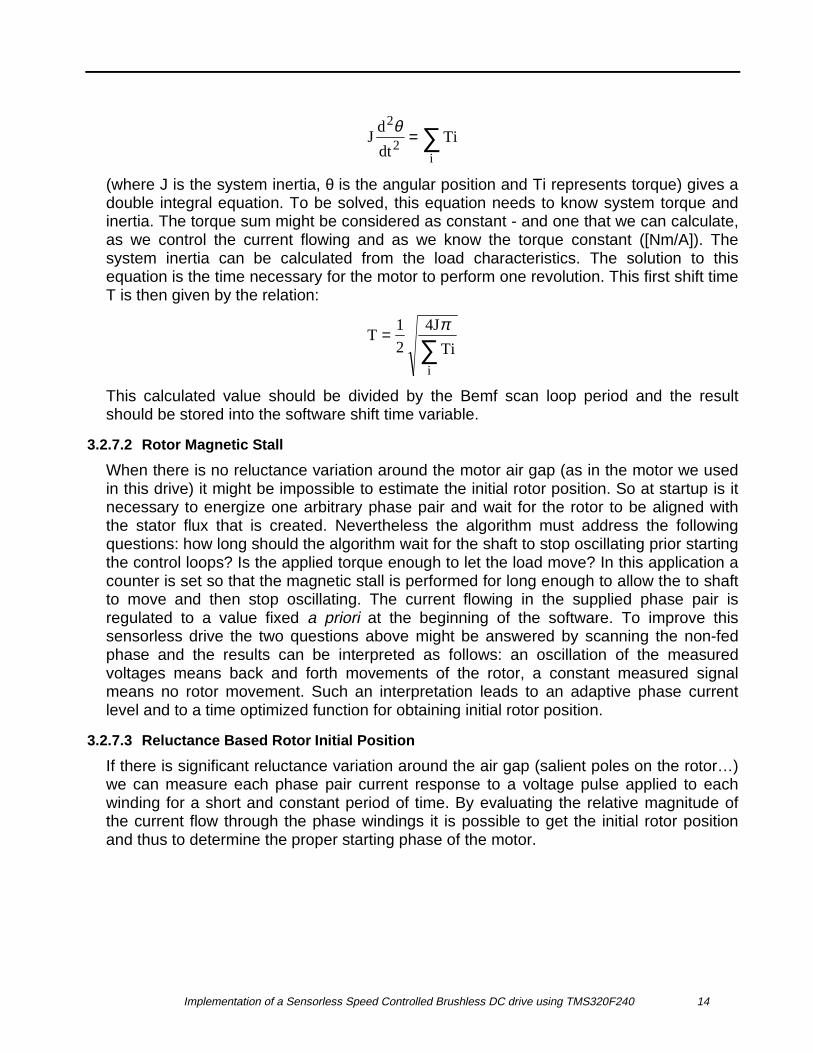
θ = ∑(where J is the system inertia, θ is the angular position and Ti represents torque) gives adouble integral equation. To be solved, this equation needs to know system torque andinertia. The torque sum might be considered as constant - and one that we can calculate,as we control the current flowing and as we know the torque constant ([Nm/A]). Thesystem inertia can be calculated from the load characteristics. The solution to thisequation is the time necessary for the motor to perform one revolution. This first shift timeT is then given by the relation:
T1
2
4J
Tii
=∑
π
This calculated value should be divided by the Bemf scan loop period and the resultshould be stored into the software shift time variable.
3.2.7.2 Rotor Magnetic Stall
When there is no reluctance variation around the motor air gap (as in the motor we usedin this drive) it might be impossible to estimate the initial rotor position. So at startup is itnecessary to energize one arbitrary phase pair and wait for the rotor to be aligned withthe stator flux that is created. Nevertheless the algorithm must address the followingquestions: how long should the algorithm wait for the shaft to stop oscillating prior startingthe control loops? Is the applied torque enough to let the load move? In this application acounter is set so that the magnetic stall is performed for long enough to allow the to shaftto move and then stop oscillating. The current flowing in the supplied phase pair isregulated to a value fixed a priori at the beginning of the software. To improve thissensorless drive the two questions above might be answered by scanning the non-fedphase and the results can be interpreted as follows: an oscillation of the measuredvoltages means back and forth movements of the rotor, a constant measured signalmeans no rotor movement. Such an interpretation leads to an adaptive phase currentlevel and to a time optimized function for obtaining initial rotor position.
3.2.7.3 Reluctance Based Rotor Initial Position
If there is significant reluctance variation around the air gap (salient poles on the rotor…)we can measure each phase pair current response to a voltage pulse applied to eachwinding for a short and constant period of time. By evaluating the relative magnitude ofthe current flow through the phase windings it is possible to get the initial rotor positionand thus to determine the proper starting phase of the motor.
Implementation of a Sensorless Speed Controlled Brushless DC drive using TMS320F240 15
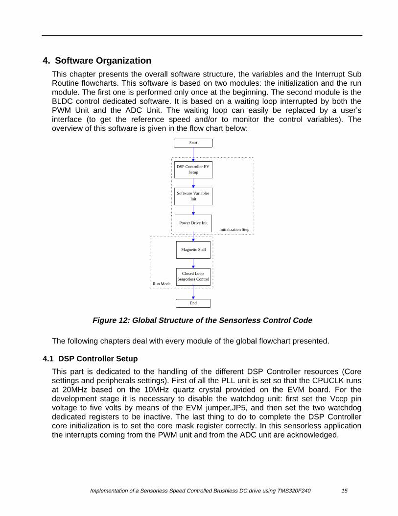
4. Software OrganizationThis chapter presents the overall software structure, the variables and the Interrupt SubRoutine flowcharts. This software is based on two modules: the initialization and the runmodule. The first one is performed only once at the beginning. The second module is theBLDC control dedicated software. It is based on a waiting loop interrupted by both thePWM Unit and the ADC Unit. The waiting loop can easily be replaced by a user’sinterface (to get the reference speed and/or to monitor the control variables). Theoverview of this software is given in the flow chart below:
Start
End
Closed Loop Sensorless Control
Magnetic Stall
Power Drive Init
Software Variables Init
DSP Controller EV Setup
Initialization Step
Run Mode
Figure 12: Global Structure of the Sensorless Control Code
The following chapters deal with every module of the global flowchart presented.
4.1 DSP Controller Setup
This part is dedicated to the handling of the different DSP Controller resources (Coresettings and peripherals settings). First of all the PLL unit is set so that the CPUCLK runsat 20MHz based on the 10MHz quartz crystal provided on the EVM board. For thedevelopment stage it is necessary to disable the watchdog unit: first set the Vccp pinvoltage to five volts by means of the EVM jumper,JP5, and then set the two watchdogdedicated registers to be inactive. The last thing to do to complete the DSP Controllercore initialization is to set the core mask register correctly. In this sensorless applicationthe interrupts coming from the PWM unit and from the ADC unit are acknowledged.
Implementation of a Sensorless Speed Controlled Brushless DC drive using TMS320F240 16
Now let us have a look at the initialization of the peripherals. To generate the necessarypulsed signals to the power electronics board the Full Compare Unit is used. It is set togenerate symmetrical non-complementary PWM signals at the frequency of 80kHz withTIMER1 as time base and with the DEADBAND unit disabled. The PWM resolution isequal to the CPUCLOCK period: 50ns. The new duty cycle reloads are made on the timercounter zero crossing at the frequency of 20kHz. The PWM unit is also set to generateone interrupt when the timer counter reaches the timer 1 period value. Finally, the ADCunit is set to receive the Start Of Conversion from software and to generate an interruptrequest to the core when the conversion is finished.
4.2 Software Variables Initialization
The second initialization step is the variable initialization. In this software 19 variables areneeded, they are described in this chapter. They can be sorted into five categories:variables which are dedicated to the Bemf scanning function, to the commutationalgorithm, to the rotor magnetic stall, to the current regulator and to the speed regulator.
4.2.1 Bemf Scanning function variables
The six variables used for this function are CUR_COUNT, V1, V2, V3, NEUTRAL,OFFSET and FLAG. All of these variables are initialized to zero.
CUR_COUNT is used in the PWM period interrupt as a PWM interrupt counter. It is usedin order to know whether or not a conversion should be started (cf figure 6).
V1, V2 and V3 are used in the ADC interrupt to save the respective phase terminalconverted voltages.
NEUTRAL is also used in the ADC interrupt to store the computed neutral voltage. As ittakes a shorter time to perform a multiplication than a division, NEUTRAL simply containsthe sum of the three phase voltages rather than one third of the sum of the three phasevoltages. The Bemf computation is performed by subtracting Neutral from three times thedesired phase voltage. Fifteen CPU cycles are saved in this way.
OFFSET is computed in the speed control loop but is used in the SEQUENCE function.OFFSET is the single Bemf correction computed in this software; it is subtracted from theBemf before comparing the Bemf to zero.
FLAG is set to one when the Bemf changes sign. When this flag is equal to one, the signchange detection is no longer performed until the next phase pair has been commutated.This is to make sure that there will not be any ripple in the sign change detection, thusmaking it possible to achieve very precise commutation angles.

Implementation of a Sensorless Speed Controlled Brushless DC drive using TMS320F240 17
4.2.2 Commutation Algorithm Variables
The variables used to compute the phase commutation point are ASYM, CAPT,B2COUNT. They are all initialized to zero.
The current 60º sector is stored in the CAPT variable. As CAPT is used in theSEQUENCE function to branch to the code which gives the right ACTR register setting,the values that it can take are 0, 2, 4, 6, 8, 10, 12 (corresponding respectively to sector#1, 2, 3, 4, 5, 6).
ASYM is used as a counter in the SEQUENCE function. This counter is reset to zeroevery time a phase commutation occurs. It increments at each new current regulationloop (in other words at each new neutral point voltage computation or, that is, every50µs) and up to the time it reaches the predefined value. Before reaching the predefinedvalue the computed Bemf is not taken into account. This counter function filters theimbalance of the three phase system created by the commutation. The predefined valueis application dependent (power board design, direct current driven) and should beadjusted to each new drive.
B2COUNT is used as a counter in the ADC interrupt. As soon as the Bemf crosses zerothis counter is loaded with the computed shift time. This counter, once loaded,decrements every 50µs and when it reaches zero the phases are commutated.
4.2.3 Rotor Magnetic Stall Variables
The variables used in this function are SPEEDFLAG, BCOUNT and STALL.
BCOUNT is used in the ADC interrupt during the rotor magnetic stall as a counter. Thiscounter increments every 50µs (every current regulation loop) until a preset value. Thispreset value defines how many times the software has to stall the rotor in order to let theshaft stop oscillating prior starting the closed loop control.
Once the BCOUNT counter reaches the predefined value, the STALL variable is set toone. This variable is used as a flag which enables the closed loop control when set toone.
SPEEDFLAG is a flag variable which (when set to one) disables any speed regulationduring the first revolution. This implies that the motor runs the first revolution with aregulated constant torque. This flag is reset to zero when the first revolution has beencompleted thus allowing the speed control to run in closed loop.
4.2.4 Current Loop Variables
The variables used for this function are Idc_ref, Idc_errorK, COMP and FLAGCUR.These variables are initialized to zero apart from COMP, which is set equal to the PWMperiod.
Implementation of a Sensorless Speed Controlled Brushless DC drive using TMS320F240 18
Idc_ref is the variable used to store the direct current reference given by the speedregulation. Idc_errorK is used to store the current error before using it. COMP is theoutput of the current regulator (in other words this is the updated duty cycle).
FLAGCUR is the flag used to tell the background waiting loop that it is time to give theinverter the new ACTR settings and the new duty cycle. After completion of these tasksFLAGCUR is reset to zero in the SEQUENCE function.
4.2.5 Speed Loop Variables
The variables used here are SPEED_REF, SPEED_COUNT, BCOUNT, FLAGUP andthe auxiliary register AR3.
SPEED_COUNT is used in the ADC interrupt to know if it is time to update the speedregulation loop. SPEED_REF is used to store the desired speed value.
FLAGUP is initialized to zero and is set to one once a mechanical revolution has beencompleted. If FLAGUP is equal to one, then the revolution time is divided by 12 (onetwelfth of a revolution is a 30º shift angle) and the result is stored into BCOUNT. So,during closed loop control, BCOUNT is the variable which contains the shift time (thisshift time will be loaded into B2COUNT after any BEMF zero crossing).
Every 50µs the auxiliary register AR3 is incremented at the beginning of the SEQUENCEfunction. So after one complete revolution AR3 register contains the previous revolutiontime. The largest value that AR3 might contain is #0FFFFh (65535). Multiplying by 50µsgives 3.27s (the time to complete one revolution). So in this software the lowest speedreachable is 19rpm.
4.3 Interrupts Flow Charts
The time diagram of the incoming interrupts is given by figure 6. The forthcomingchapters present the interrupt internal organizations. Some software features are realizedin the interrupt subroutines and some are performed outside. Interrupt operationsperformed inside are: the starts of conversion, current regulation, neutral point voltagecomputation, speed update calculation and phase commutation. Interrupt operationsperformed outside are: Bemf computation, Bemf sign change detection, three phasesystem asymmetry correction and PWM output. Calling the outside functions is ensuredby flags that are polled in the waiting loop and set inside the interrupts.
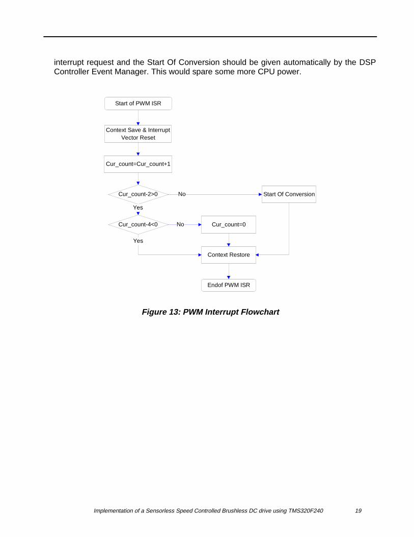
4.3.1 PWM Unit Interrupt Flowchart
The interrupt request is generated every PWM period (cf figure 6, note that the PWMperiod interrupt is NOT the PWM Timer period interrupt). The flowchart below depicts theISR organization. The PWM period interrupt lasts a maximum of 30 CPU cycles (1.5µs)and thus needs 2.4MIPS among the 20 available. With some changes the scheme belowcan be used with another chopping frequency: let us assume a 20kHz choppingfrequency and a 10kHz current loop frequency. In this case a conversion should bestarted at every PWM period. So there is no longer any need to acknowledge the PWM
Implementation of a Sensorless Speed Controlled Brushless DC drive using TMS320F240 19
interrupt request and the Start Of Conversion should be given automatically by the DSPController Event Manager. This would spare some more CPU power.
Start of PWM ISR
Cur_count=Cur_count+1
Context Save & Interrupt Vector Reset
Cur_count-2>0
Cur_count-4<0 Cur_count=0
Context Restore
Endof PWM ISR
Start Of ConversionNo
Yes
Yes
No
Figure 13: PWM Interrupt Flowchart
Implementation of a Sensorless Speed Controlled Brushless DC drive using TMS320F240 20
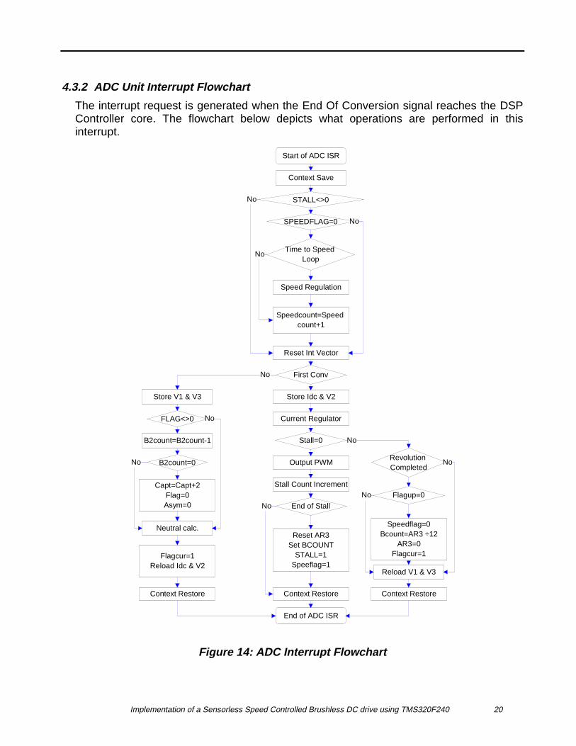
4.3.2 ADC Unit Interrupt Flowchart
The interrupt request is generated when the End Of Conversion signal reaches the DSPController core. The flowchart below depicts what operations are performed in thisinterrupt.
Start of ADC ISR
Context Save
STALL<>0
SPEEDFLAG=0
Time to Speed Loop
Speedcount=Speed count+1
Speed Regulation
Reset Int Vector
First Conv
Current Regulator
Output PWM
Stall Count Increment
Stall=0
End of Stall
Reset AR3Set BCOUNT
STALL=1Speeflag=1
Store Idc & V2Store V1 & V3
FLAG<>0
B2count=B2count-1
B2count=0
Capt=Capt+2Flag=0Asym=0
Neutral calc.
Flagcur=1Reload Idc & V2
Context Restore Context Restore
End of ADC ISR
Revolution Completed
Flagup=0
Speedflag=0Bcount=AR3 ÷12
AR3=0Flagcur=1
Reload V1 & V3
Context Restore
No
No
No
No
No
No
No
No
No
No
Figure 14: ADC Interrupt Flowchart
Implementation of a Sensorless Speed Controlled Brushless DC drive using TMS320F240 21
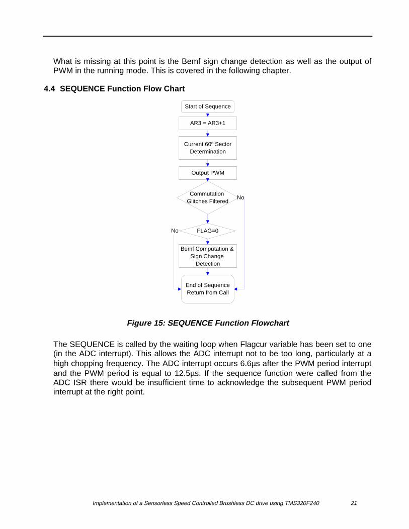
What is missing at this point is the Bemf sign change detection as well as the output ofPWM in the running mode. This is covered in the following chapter.
4.4 SEQUENCE Function Flow Chart
Start of Sequence
AR3 = AR3+1
Current 60º SectorDetermination
Output PWM
Commutation Glitches Filtered
FLAG=0
Bemf Computation & Sign Change
Detection
End of SequenceReturn from Call
No
No
Figure 15: SEQUENCE Function Flowchart
The SEQUENCE is called by the waiting loop when Flagcur variable has been set to one(in the ADC interrupt). This allows the ADC interrupt not to be too long, particularly at ahigh chopping frequency. The ADC interrupt occurs 6.6µs after the PWM period interruptand the PWM period is equal to 12.5µs. If the sequence function were called from theADC ISR there would be insufficient time to acknowledge the subsequent PWM periodinterrupt at the right point.
Implementation of a Sensorless Speed Controlled Brushless DC drive using TMS320F240 22
5. SummaryThis document deals with obtaining the rotor position of a sensorless Brush Less DCdrive by means of software. This single chip solution is based entirely on theTMS320x24x DSP Controller capabilities: namely, high 2xx DSP core CPU power andextremely versatile peripherals. This solution replaces the position sensor cost at no costother than software development. Furthermore, this solution increases the drive reliabilityas the position information will no longer be sensitive to temperature or vibration. Thismakes the sensorless solution really cost effective and reliable. Assuming that the initialrotor position is detectable and knowing that this solution runs closed loop from quasizero speed, it is apparent that this sensorless drive might advantageously replace thesensored solution in a wide range of speed control applications.
References
Implementation of a Sensorless Speed Controlled Brushless DC drive using TMS320F240 23
References
1. TMS320C24x DSP Controllers - Reference Set: Vol.1, Texas Instruments Inc,1997.
2. TMS320C24x DSP Controllers - Reference Set: Vol.2 Texas Instruments Inc,1997.
3. Implementation of a Speed Controlled Brushless DC Drive usingTMS320F240, Texas Instruments Inc., 1997 part #BPRA064.
4. DSP Solutions for BLDC Motors, Texas Instruments Inc.,1997 part#BPRA055.
5. DC 12-24V 30A Three Phase Power Hardware for either PMSM or ACInduction Machine, Texas Instruments Inc.,1997 part #BPRA071.
Appendix A Sensorless BLDC Drive Control Assembly Code
Implementation of a Sensorless Speed Controlled Brushless DC drive using TMS320F240 24
Appendix A Sensorless BLDC Drive Control Assembly Code
;********************************************************; File Name : sensor.asm;; Target System : c240 evm;; Description : BLDC motor speed controlled; 40W 18V July/97; Sensorless Speed control based on; Bemf measurement.; Magnetic Stall at start up.; Phases’ use imbalance Correction; Commutation dV/dt and dI/dT filtering;;Date September 1997;*********************************************************
.include "c240app.h";-------------------------------------------;Current regulator coeff setting;-------------------------------------------Kp .set 280 ;Q11 (1=2048) Kp=0.12
;-------------------------------------------;Speed regulator coeff setting;-------------------------------------------Kps .set 100 Kis .set 100;-------------------------------------------; Variable definitions;-------------------------------------------
.bss CAPT,1 ; capt indication
.bss COMP,1
.bss Idc_ref,1
.bss Idc_errorK,1
.bss FLAGCUR,1
.bss CUR_COUNT,1
.bss SPEED_REF,1
.bss SPEED_COUNT,1
.bss V1,1
.bss V2,1
.bss V3,1
.bss NEUTRAL,1
.bss FLAG,1
.bss FLAGUP,1
.bss BCOUNT,1
.bss B2COUNT,1
.bss STALL,1
.bss ASYM,1
.bss SPEEDFLAG,1
.bss OFFSET,1
.bss stack,6
;======================================; Reset & interrupt vectors;======================================
.sect "vectors"RSVECT B _c_int0
.space 16*2INT2 B PWMINT ;Assign PWM interrupt vector
Appendix A Sensorless BLDC Drive Control Assembly Code
Implementation of a Sensorless Speed Controlled Brushless DC drive using TMS320F240 25
.space 16*6INT6 B ADCINT ;Assign ADC interrupt vector
.space 16*38
.text
.global _c_int0_c_int0
SETC CNFCLRC OVM ;Reset overflow modeSETC SXM ;Reset sign extension modeCLRC XF ;Reset debugging pinSETC INTM ;Set global interrupt mask
MAR *,AR2 ;Auxiliary Registers InitLAR AR2,#0300hSPLK #0,*+SPLK #0,*+SPLK #0,*+SPLK #0,*+SPLK #0,*+SPLK #0,*+SPLK #0,*+SPLK #0,*+SPLK #0,*+SPLK #0,*+SPLK #0,*+SPLK #0,*+SPLK #0,*+SPLK #0,*+LAR AR2,#0300hLAR AR1,#stackLAR AR3,#0307h
;Disable watchdog (Vccp=5v)& watchdog counter reset p6-12LDP #00E0hSPLK #0006Fh, WD_CNTLSPLK #05555h, WD_KEYSPLK #0AAAAh, WD_KEY
; initialize WDT registersSPLK #06Fh, WD_CNTL ; clear WDFLAG, Disable WDT, set WDT for 1
; Set up CLKOUT to be SYSCLK p6-6 SPLK #40C0h,SYSCR
LACC SYSSRAND #069FFhSACL SYSSR
;set up PLL clockin=10Mhz,CPUCLOCK=20Mhz,SYSCLK=10Mhz SPLK #0002h,CKCR0 ; PLL disabled
SPLK #00b1h,CKCR1 SPLK #0081h,CKCR0;Set up one Wait States for I/O space (DAC needs one wait state)
MAR *,AR1LACC #0004hSACL *OUT *,WSGR
;I/O setting p11-11LDP #00E1h
Appendix A Sensorless BLDC Drive Control Assembly Code
Implementation of a Sensorless Speed Controlled Brushless DC drive using TMS320F240 26
SPLK #0000fh, OCRASPLK #0070h, OCRBSPLK #02800h, PBDATDIR ;Clear Fault and no Shut DownLACC PBDATDIR
; Clear EV control registersLDP #0E8hSPLK #0000h,T1CON ;no timer enableSPLK #0000h,T1PER ;no timer features enable
SPLK #0000h,T1CNTSPLK #0000h,T1CMPSPLK #0000h,T2CON
SPLK #0000h,T2PER SPLK #0000h,T2CNT
SPLK #0000h,T2CMPSPLK #0000h,T3CON
SPLK #0000h,T3PER SPLK #0000h,T3CNT
SPLK #0000h,T3CMPSPLK #0000h,COMCONSPLK #0000h,DBTCONSPLK #0000h,ACTRSPLK #0000h,SACTRSPLK #0000h,CMPR1SPLK #0000h,CMPR2SPLK #0000h,CMPR3SPLK #0000h,SCMPR1SPLK #0000h,SCMPR2SPLK #0000h,SCMPR3SPLK #0000h,CAPCON ;no capture enableSPLK #00ffh,CAPFIFOLACC FIFO1LACC FIFO2LACC FIFO3
;PWM Unit settingSPLK #0125,T1PERSPLK #0000h,T1CNTSPLK #0FFFh,ACTRSPLK #0508h,DBTCONSPLK #00125,CMPR1SPLK #00125,CMPR2SPLK #00125,CMPR3SPLK #0287h,COMCONSPLK #8287h,COMCONSPLK #2800h,T1CONSPLK #2840h,T1CONSPLK #0000h,GPTCON
;Capture Unit SettingSPLK #0b0fch,CAPCONSPLK #00ffh,CAPFIFO
;Core Mask SettingLDP #0LACC #022H ;ADC and Group A Interrupt Core MaskSACL IMRLACC IFR ;Clear Core Flag RegisterSACL IFR
;EV Mask Setting, Vector & Flag reset p11-46LDP #0E8h
Appendix A Sensorless BLDC Drive Control Assembly Code
Implementation of a Sensorless Speed Controlled Brushless DC drive using TMS320F240 27
LACC IFRASACL IFRALACC IFRBSACL IFRBLACC IFRCSACL IFRCSPLK #0200H,IMRASPLK #0,IMRBSPLK #7,IMRCLACC IVRALACC IVRBLACC IVRC
;ADC Unit setting p3-8LDP #0E0hSPLK #0003h,ADCTRL2SPLK #1b6ah,ADCTRL1 ;ADC 14&5
CLRC INTM
LDP #0SPLK #020H,Idc_ref ;Magnetic Stall Desired CurrentSPLK #0,Idc_errorKSPLK #0300H,SPEED_REF ;Speed ReferenceSPLK #00112,COMP ;Minimum Duty CycleSPLK #0000,CUR_COUNTSPLK #0000,FLAGCURSPLK #0000,SPEED_COUNTSPLK #0000H,CAPTSPLK #0000H,V1SPLK #0000H,V2SPLK #0000H,V3SPLK #0000H,NEUTRALSPLK #0000H,FLAGSPLK #0001H,FLAGUPSPLK #0000H,BCOUNTSPLK #0000H,B2COUNTSPLK #0000H,STALLSPLK #0000H,ASYMSPLK #0000H,OFFSET
MAR *,AR2LAR AR2,#0300h
FAULT_CLEARLDP #0E1h ;Check if the Pre Driver SignalLACC PBDATDIR ;Is ClearedAND #010hBZ FAULT_CLEARSPLK #02820h,PBDATDIR ;If cleared then stop Clear Fault
LDP #0LACC COMP ;Load Duty Cycle and SetLDP #0E8h ;PWM Register for the MagneticSPLK #03FDh,ACTR ;Stall FunctionSACL CMPR1SPLK #0FFFH,CMPR2SPLK #0FFFH,CMPR3
MAGSTALLLDP #0 ;Check if the Magnetic Stall is
Appendix A Sensorless BLDC Drive Control Assembly Code
Implementation of a Sensorless Speed Controlled Brushless DC drive using TMS320F240 28
LACC STALL ;TerminatedBZ MAGSTALL
;Set next commutation sequenceLACC COMP ;If so then set the ACTR RegisterLDP #0E8h ;to commutate the next phase pair.SPLK #03DFh,ACTRSACL CMPR2SPLK #0FFFFH,CMPR3SPLK #0FFFFH,CMPR1
LDP #0 ;Trace of the current 60º sectorSPLK #4,CAPT
LOOPLDP #0LACC FLAGCURBZ LOOP ;Time to update the Duty Cycle?SPLK #0,FLAGCURCALL SEQUENCE ;If yes the Call Sequence functionB LOOP ;Then wait for the next updated Duty Cycle
SEQUENCEMAR *,AR3` ;Revolution Time CounterLAR AR3,#0307HLACC *ADD #1SACL *
LDP #0 ;Which CMPR register should be updatedLACC CAPT ;with the new duty cycle?ADD #CAPT_DETERBACC
CAPT_DETERB RISING1B FALLING3B RISING2B FALLING1B RISING3
FALLING2LACC COMP ;Input Current Path: Phase CLDP #0E8h ;Output Current Path: Phase BSPLK #0D3FH,ACTR ;Non Fed Phase: Phase ASACL CMPR3SPLK #0FFFH,CMPR2SPLK #0FFFH,CMPR1
;Commutation glitches filterLDP #0LACC ASYMADD #1SACL ASYMSUB #10BLEZ ENDSPLK #10,ASYM
;Zero already crossed?LDP #0LACC FLAG ;Did BemfA sign already changed?BNZ END ;If yes then END
;Else:
Appendix A Sensorless BLDC Drive Control Assembly Code
Implementation of a Sensorless Speed Controlled Brushless DC drive using TMS320F240 29
;Bemf zero crossing detectionLDP #0LACC V1,1ADD V1 ;ACC=3*(BemfA + Neutral)SUB NEUTRAL ;ACC=3*BemfASUB OFFSET ;ACC=3*BemfA correctedBLZ END ;Sign Change?SPLK #1,FLAG ;BemfA Sign has changedLACC BCOUNT ;Load Shift Time.SACL B2COUNTB END
RISING3LACC COMP ;Input Current Path Phase CLDP #0E8h ;Output Current Path Phase ASPLK #0DF3H,ACTR ;Non Fed Phase phase BSACL CMPR3SPLK #0FFFH,CMPR2SPLK #0FFFH,CMPR1
;Commutation glitches filterLDP #0LACC ASYMADD #1SACL ASYMSUB #10BLEZ ENDSPLK #10,ASYM
;Zero crossed?LDP #0LACC FLAG ;Did bemfB sign already changed?BNZ END ;If yes then END
;Else;Bemf zero detectionLACC V2,1ADD V2 ;ACC=3*(BemfB + Neutral)SUB NEUTRAL ;ACC=3*BemfBBGEZ END ;Sign Changed?SPLK #1,FLAG ;Bemf Sign Has ChangedLACC BCOUNT ;Load Shift TimeSACL B2COUNTB END
FALLING3LACC COMP ;Input Current Path Phase ALDP #0E8h ;Output Current Path Phase CSPLK #03FDH,ACTR ;Non Fed Phase Phase BSACL CMPR1SPLK #0FFFH,CMPR2SPLK #0FFFH,CMPR3
;Commutation glitches filterLDP #0LACC ASYMADD #1SACL ASYMSUB #10BLEZ ENDSPLK #10,ASYM
;Zero crossed?
Appendix A Sensorless BLDC Drive Control Assembly Code
Implementation of a Sensorless Speed Controlled Brushless DC drive using TMS320F240 30
LDP #0LACC FLAG ; Did BemfB sign changed already?BNZ END ;If yes then END
;Else:;Bemf zero detectionLACC V2,1ADD V2 ;ACC=3*(BemfB + Neutral)SUB NEUTRAL ;ACC=3*BemfBSUB OFFSET ;ACC=3*BemfB correctedBLZ END ;Sign Changed?SPLK #1,FLAG ;Bemf sign has changedLACC BCOUNT ;Load Shift TimeSACL B2COUNTB END
RISING2LACC COMP ;Input Current Path: Phase BLDP #0E8h ;Output Current Path: Phase CSPLK #03DFH,ACTR ;Non fed phase Phase ASACL CMPR2SPLK #0FFFH,CMPR3SPLK #0FFFH,CMPR1
;Commutation glitches filterLDP #0LACC ASYMADD #1SACL ASYMSUB #10BLEZ ENDSPLK #10,ASYM
;Zero crossed?LDP #0LACC FLAG ;Did BemfA sign already changed?BNZ END ;If yes then END
;Else:;Bemf zero detectionLACC V1,1ADD V1 ;ACC=3*(BemfA + Neutral)SUB NEUTRAL ;ACC=3*BemfABGEZ END ;Sign Changed?SPLK #1,FLAG ;BemfA Sign has ChangedLACC BCOUNT ;Load Shift TimeSACL B2COUNTB END
RISING1LACC COMP ;Input Current Path Phase ALDP #0E8h ;Output Current Path Phase BSPLK #0F3DH,ACTR ;Non fed phase Phase CSACL CMPR1SPLK #0FFFH,CMPR2SPLK #0FFFH,CMPR3
;Commutation glitches filterLDP #0LACC ASYMADD #1SACL ASYMSUB #10BLEZ END
Appendix A Sensorless BLDC Drive Control Assembly Code
Implementation of a Sensorless Speed Controlled Brushless DC drive using TMS320F240 31
SPLK #10,ASYM
;Zero crossed?LDP #0LACC FLAG ;Did BemfC sign already changed?BNZ END ;If yes then END
;Else:;Bemf zero detectionLDP #0LACC V3,1ADD V3 ;ACC=3*(BemfC + Neutral)SUB NEUTRAL ;ACC=3*BemfCBGEZ END ;Sign Changed?SPLK #1,FLAG ;BemfC Sign has changedLACC BCOUNT ;Load Shift TimeSACL B2COUNTB END
FALLING1LACC COMP ;Input Current Path Phase BLDP #0E8h ;Output Current Path Phase ASPLK #0FD3H,ACTR ;Non fed phase Phase CSACL CMPR2SPLK #0FFFH,CMPR3SPLK #0FFFH,CMPR1
;Commutation glitches filterLDP #0LACC ASYMADD #1SACL ASYMSUB #10BLEZ ENDSPLK #10,ASYM
;Zero crossed?LDP #0SPLK #0,FLAGUPLACC FLAG ; Did BemfC sign already changed?BNZ END ;If Yes then END
;Else;Bemf zero detectionLDP #0LACC V3,1ADD V3 ;ACC=3*(BemfC + Neutral)SUB NEUTRAL ;ACC=3*BemfCSUB OFFSET ;ACC=3*Bemf3 correctedBLZ END ;Sign Changed?SPLK #1,FLAG ;BemfC Sign has changedLACC BCOUNT ;Load Shift TimeSACL B2COUNT
ENDRET
SPEED_REG MAR *,AR2
LAR AR2,#0303h ;Speed error Pointer InitLDP #0SPLK #32,SPEED_COUNT ;Speed Error Shifter setting
;Speed and speed error calc
Appendix A Sensorless BLDC Drive Control Assembly Code
Implementation of a Sensorless Speed Controlled Brushless DC drive using TMS320F240 32
CLRC SXMZACOR #0FFFFHRPT #15SUBC BCOUNTAND #0FFFFH ;Acc=1 / (rev. time/ 12) = SpeedSETC SXMSUB SPEED_REFNEG ;Acc= Spd ref-Spd Fb= Spd error
;Speed error limitationBGEZ POSABSSPLK #-32,SPEED_COUNT
POSSACL *
SUB #03FFH BLEZ OKPOS SPLK #03FFH,*OKPOS LT * ;-1024 < Speed error < 1024 MPY SPEED_COUNT PAC SACL * ;Speed error <<5
;Speed regulationLT *MPY #KpsPACADD Idc_ref,16SACH Idc_ref ;Idc_ref(k)=Idc_ref(k-1) + K*Speed_error(k)
;Idc_ref compensation LACC Idc_ref
BGEZ RESSPLK #0,Idc_ref
;Reset Speed loop timer
RESLACC SPEED_REF,11 ;Bemf correction computationSACH OFFSETSPLK #0,SPEED_COUNTRET
PWMINT;save status registersMAR *,AR1MAR *+ ; skip one positionSST #1, *+ ; save ST1SST #0, *+ ;save ST0SACH *+ ;save acc highSACL * ;save acc low
LDP #0E8H ;Clear Interrupt VectorLACC IVRA
LDP #0LACC CUR_COUNTADD #1SACL CUR_COUNTSUB #2BGZ CONV ;Time to start a Conversion?
Appendix A Sensorless BLDC Drive Control Assembly Code
Implementation of a Sensorless Speed Controlled Brushless DC drive using TMS320F240 33
LDP #0E0HLACC ADCTRL1OR #02000HSACL ADCTRL1B CONTEXT
CONVSUB #2 ;Reset CUR_COUNT variable?BLZ CONTEXTSPLK #0,CUR_COUNT
CONTEXT;restore status registersMAR *, AR1 ; make stack pointer activeLACL *- ;Restore Acc lowADDH *- ;Restore Acc highLST #0, *- ; load ST0LST #1, *- ; load ST1
CLRC INTMRET
ADCINTMAR *,AR1MAR *+ ; skip one positionSST #1, *+ ; save ST1SST #0, *+ ; save ST0SACH *+ ;save acc highSACL * ;save acc low
;Magnetic stall flagLDP #0LACC STALLBZ Vdc_or_Idc ;If Magnetic Stall is cur. Performed then
;Branch to Vdc_or_IdcLACC SPEEDFLAG ;If the first Revolution has not beenBNZ Vdc_or_Idc ;Completed then branch to Vdc_or_Idc
;Time to speed loop?LACC SPEED_COUNTSUB #2000BNZ NO_SPEED_REGCALL SPEED_REG ;If Time then Speed Loop
NO_SPEED_REGLACC SPEED_COUNTADD #1SACL SPEED_COUNT
;Vdc OR Idc?Vdc_or_Idc LDP #0E0h
LACC SYSIVR ;Clear interrupt vector
LDP #0E0HLACC ADCTRL1AND #0002HBZ Vdc ;If second conv then branch to Vdc
;current error calculationCLRC SXMLACC ADCFIFO1,10 ;high Acc = IdcADD ADCFIFO2 ;low Acc = V2<<6
Appendix A Sensorless BLDC Drive Control Assembly Code
Implementation of a Sensorless Speed Controlled Brushless DC drive using TMS320F240 34
LDP #0SACH Idc_errorK ;Store IdcSACL V2 ;Store V2<<6LACC V2,10SACH V2 ;Store V2SETC SXM
LACC Idc_errorK,5SUB Idc_ref,5SACL Idc_errorK ;Store Current error<<5
;Current regulationLT Idc_errorKMPY #KpPAC ;Acc = Kp*Current_errorADD COMP,16SACH COMP ;Store Kp*Current_error + COMP(k-1)LACC COMP ;Load updated Duty cycle
;current reg output limitationBGZ SUP_LIMSPLK #0,COMPB COMP_OK
SUP_LIMSUB #0112BLZ COMP_OKSPLK #0112,COMP
COMP_OK ;0 < Updated Duty cycle < Max dutyLACC STALLBNZ SPEEDUP ;If running mode Branch to SPEEDUPCLRC SXM ;Else (Magnetic Stall Performing):SPLK #2,CUR_COUNT ;Cancel second conversion startLACC COMPLDP #0E8HSACL CMPR1 ;Output Updated Magnetic Stall Duty CycleLDP #0LACC BCOUNT ;Magnetic Stall Counter IncrementADD #1SACL BCOUNTSUB #0FFFFHSETC SXMBNZ RESTO ;Is magnetic stall to the end?MAR *,AR3 ;If yes thenLAR AR3,#0307HSPLK #0,*SPLK #050H,BCOUNT ;Load first Time ShiftSPLK #1,STALL ;Enable running modeSPLK #1,SPEEDFLAGB RESTO
;Update speed?SPEEDUP
LACC CAPTSUB #4BNZ RELOAD ;Time to update speed feedback?LACC FLAGUP ;Speed feedback already updated?BNZ RELOAD ;If yes branch to RELOADMAR *,AR3LAR AR3,#0307HSPLK #0,SPEEDFLAG ;Release the first revolution indicator flagCLRC SXMLACC * ;Load the revolution time
Appendix A Sensorless BLDC Drive Control Assembly Code
Implementation of a Sensorless Speed Controlled Brushless DC drive using TMS320F240 35
SPLK #012,BCOUNTRPT #15SUBC BCOUNT ;Divide it by 12 (i.e. 30º)AND #0FFFFHSACL BCOUNT ;Store the new Shift TimeSETC SXMSPLK #0,*SPLK #1,FLAGUP ;Speed feedback updated
;Reload Vdc channelRELOAD
LDP #0E0HSPLK #1B5Ch,ADCTRL1 ;ADC 6&13
;restore contextRESTO
MAR *, AR1 ; make stack pointer activeLACL *-ADDH *-LST #0, *- ; load ST0LST #1, *- ; load ST1
CLRC INTMRET
Vdc;Read Vshunt valuesLDP #0E0HCLRC SXMLACC ADCFIFO1,10 ;Acc high = V3ADD ADCFIFO2 ;Acc low = V1<<6LDP #0SACH V3 ;Store V3SACL V1 ;Store V1<<6LACC V1,10SACH V1 ;Store V1
;Zero crossed?LACC FLAG ;Did the Bemf already crossed zero?BZ NEU ;If Not then Branch to NEU
;Commutation instantLACC B2COUNT ;If yes decrement shift time counterSUB #1SACL B2COUNT ;Store new shift time counter valueSETC SXMBNZ NEU ;Is it time to commutate a new phase pair?LACC CAPT ;If yes then upgrade the commutated phasesADD #2 ;remainderSACL CAPT ;Store the commutated phases remainderSUB #0CHBNZ OKCAPTSPLK #0,CAPT
OKCAPTSPLK #0,FLAG ;Reset flags for the new Bemf scanningSPLK #0,ASYM
;Neutral calculationNEU
LACC V1ADD V2ADD V3 ;Acc=3*neutral point voltage
Appendix A Sensorless BLDC Drive Control Assembly Code
Implementation of a Sensorless Speed Controlled Brushless DC drive using TMS320F240 36
SACL NEUTRAL ;Store 3*neutral point voltage
;output PWMSPLK #1,FLAGCUR ;Set flag to let the PWM unit to be updated
;Reload Idc channelLDP #0E0HSPLK #1b6ah,ADCTRL1 ;Loaded ADC lines: Idc and V2
;restore contextMAR *, AR1 ; make stack pointer activeLACL *-ADDH *-LST #0, *- ; load ST0LST #1, *- ; load ST1
CLRC INTMRET
Appendix B Linker File
Implementation of a Sensorless Speed Controlled Brushless DC drive using TMS320F240 37
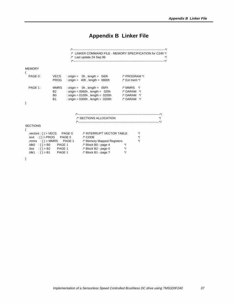
Appendix B Linker File
/*-------------------------------------------------------------------------------------------*//* LINKER COMMAND FILE - MEMORY SPECIFICATION for C240 *//* Last update 24 Sep 96 *//*------------------------------------------------------------------------------------------*/
MEMORY PAGE 0 : VECS : origin = 0h , length = 040h /* PROGRAM */
PROG : origin = 40h , length = 0800h /* Ext mem */
PAGE 1 : MMRS : origin = 0h , length = 05Fh /* MMRS */ B2 : origin = 0060h , length = 020h /* DARAM */ B0 : origin = 0100h , length = 0200h /* DARAM */ B1 : origin = 0300h , length = 0200h /* DARAM */
/*---------------------------------------------------------------------------------*//* SECTIONS ALLOCATION *//*--------------------------------------------------------------------------------*/
SECTIONS .vectors : > VECS PAGE 0 /* INTERRUPT VECTOR TABLE */ .text : > PROG PAGE 0 /* CODE */ .mmrs : > MMRS PAGE 1 /* Memory Mapped Registers */ .blk0 : > B0 PAGE 1 /* Block B0 - page 4 */ .bss : > B2 PAGE 1 /* Block B2 - page 0 */ .blk1 : > B1 PAGE 1 /* Block B1 - page ? */