Embed Size (px)
Citation preview

Chapter 3
Implementing an EIGRP Solution
This chapter contains the following sections:
Dynamic Routing Review
EIGRP Features and Function
Troubleshooting EIGRP
Implementing EIGRP for IPv6
Chapter Summary
Review Questions
EIGRP, Enhanced Interior Gateway Protocol, is an advanced distance vector routing protocol that was developed by Cisco over 20 years ago. It is suited for many different topologies and media. EIGRP scales well and provides extremely quick convergence times with minimal overhead. EIGRP performs in both well-designed networks and poorly designed networks. It is a popular choice for a routing protocol on Cisco devices. EIGRP did have a predecessor, Interior Gateway Protocol (IGRP), which is now obsolete and is not included in Cisco IOS 15.
EIGRP was historically a Cisco proprietary and closed protocol. However, as of this writing, Cisco is in the process of releasing the basic functions to the IETF as an RFC (Request For Comments, a standards document; see http://tools.ietf.org/html/draft-savage-eigrp-00 ).
This chapter begins with a review of dynamic routing. It then examines the operation, confi guration, and troubleshooting of EIGRP for IPv4 and IPv6.

92 Interconnecting Cisco Network Devices, Part 2 (ICND2) Foundation Learning Guide, Fourth Edition
Chapter Objectives:
Review key concepts for Dynamic Routing Protocols
Understand how a Cisco Router populates its routing table
Understand the features, operation, theory, and functions of EIGRP
Configure and troubleshoot EIGRP for IPv6 and IPv4
Dynamic Routing Review
A dynamic routing protocol is a set of processes, algorithms, and messages that is used to exchange routing and reachability information within the internetwork. Without a dynamic routing protocol, all networks, except those connected directly with the router, must be statically defined. Dynamic routing protocols can react to changes in conditions in the network, such as failed links.
Routing
All routing protocols have the same purpose: to learn about remote networks and to quickly adapt whenever there is a change in the topology. The method that a routing pro-tocol uses to accomplish this purpose depends upon the algorithm that it uses and the operational characteristics of the protocol. The performance of a dynamic routing proto-col varies depending on the type of routing protocol.
Although routing protocols provide routers with up-to-date routing tables, there are costs that put additional demands on the memory and processing power of the router. First, the exchange of route information adds overhead that consumes network bandwidth. This overhead can be a problem, particularly for low-bandwidth links between routers. Second, after the router receives the route information, the routing protocol needs to pro-cess the information received. Therefore, routers that employ these protocols must have sufficient resources to implement the algorithms of the protocol and to perform timely packet routing and forwarding.
Routing Domains
An autonomous system (AS), otherwise known as a routing domain, is a collection of routers under a common administration. A typical example is an internal network of a company and its interconnection to the network of an ISP. The ISP and a company’s inter-nal network are under different control. Therefore, they need a way to interconnect. Static routes are often used in this type of a scenario. However, what if there are multiple links between the company and the ISP? What if the company uses more than one ISP? Static routing protocols would not be suitable. To connect the entities, it is necessary to estab-lish communication with the bodies under different administration. Another example would be a merger, acquisition, or development of a subsidiary that maintains its own IT resources. The networks may need to be connected, but they also may need to be main-

Chapter 3: Implementing an EIGRP Solution 93
tained as separate entities. There must be a way to communicate between the two. The third example, which is intimated by the first, is the public Internet. Many different enti-ties are interconnected here as well. Figure 3-1 is a representation of three autonomous systems, one for a private company and two ISPs.
AS 100ISP1
External Link
AS 200Company’s Private
Network
External Link
AS 300 ISP2
Figure 3-1 Connection of Three Distinct Autonomous Systems (AS)
To accommodate these types of scenarios, two categories of routing protocols exist:
Interior Gateway Protocols (IGP): These routing protocols are used to exchange routing information within an autonomous system. EIGRP, IS-IS (Intermediate System-to-Intermediate System) Protocol, RIP (Routing Information Protocol), and OSPF (Open Shortest Path First) Protocol are examples of IGPs.
Exterior Gateway Protocols (EGP): These routing protocols are used to route between autonomous systems. BGP (Border Gateway Protocol) is the EGP of choice in networks today. The Exterior Gateway Protocol, designed in 1982, was the first EGP. It has since been deprecated in favor of BGP and is considered obsolete. BGP is the routing protocol used on the public Internet.
Classification of Routing Protocols
EGPs and IGPs are further classified depending on how they are designed and operate. There are two categories of routing protocols:
Distance vector protocols: The distance vector routing approach determines the direction (vector) and distance (hops) to any point in the internetwork. Some distance vector protocols periodically send complete routing tables to all of the connected neighbors. In large networks, these routing updates can become enormous, causing significant traffic on the links. This can also cause slow convergence, as the whole

94 Interconnecting Cisco Network Devices, Part 2 (ICND2) Foundation Learning Guide, Fourth Edition
routing table could be inconsistent due to network changes, such as a link down, between updates. RIP is an example of a protocol that sends out periodic updates .
Distance vector protocols use routers as signposts along the path to the final destina-tion. The only information that a router knows about a remote network is the dis-tance or metric to reach that network and which path or interface to use to get there. Distance vector routing protocols do not have an actual map of the network topol-ogy. EIGRP is another example of the distance vector routing protocol. However, unlike RIP, EIGRP does not send out full copies of the routing table once the initial setup occurs between two neighboring routers. EIGRP only sends updates when there is a change.
Link-state protocols: The link-state approach, which uses the shortest path first (SPF) algorithm, creates an abstract of the exact topology of the entire internetwork, or at least of the partition in which the router is situated. Using a link-state routing protocol is like having a complete map of the network topology. Signposts along the way from the source to the destination are not necessary because all link-state rout-ers are using an identical “map” of the network. A link-state router uses the link-state information to create a topology map and select the best path to all destination net-works in the topology. Link-state protocols only send updates when there is a change in the network. BGP, OSPF, and IS-IS are examples of link-state routing protocols.
Note EIGRP was originally classified as a “hybrid” routing protocol, the combination of link state and distance vector. However, it is truly a rich-featured distance vector protocol. A major differentiator to support this is that EIGRP does not have a full picture of the topology in each node.
Classful Routing Versus Classless Routing
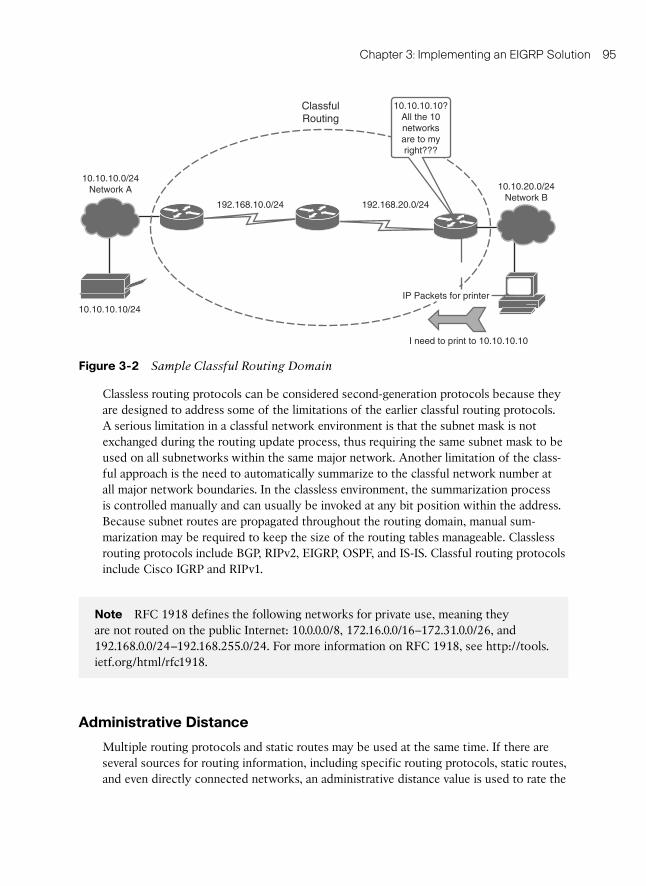
IP addresses are categorized in classes: A, B, and C. Classful routing protocols only rec-ognize networks as directly connected by class. So, if a network is subnetted, there can-not be a classful boundary in between. In Figure 3-2 , Network A cannot reach Network B using a classful routing protocol because they are separated by a different class network. The term for this scenario is discontiguous subnets .
Classful routing is a consequence when subnet masks are not disclosed in the routing advertisements that most distance vector routing protocols generate. When a classful routing protocol is used, all subnetworks of the same major network (Class A, B, or C) must use the same subnet mask, which is not necessarily a default major-class subnet mask. Routers that are running a classful routing protocol perform automatic route sum-marization across network boundaries. Classful routing has become somewhat obsolete because the classful model is rarely used on the Internet. Because IP address depletion problems occur on the Internet, most Internet blocks are subdivided using classless rout-ing and variable-length subnet masks. You will most likely see classful address allocation inside private organizations that use private IP addresses as defined in RFC 1918 in con-junction with Network Address Translation (NAT) at AS borders.
Chapter 3: Implementing an EIGRP Solution 95
Classless routing protocols can be considered second-generation protocols because they are designed to address some of the limitations of the earlier classful routing protocols. A serious limitation in a classful network environment is that the subnet mask is not exchanged during the routing update process, thus requiring the same subnet mask to be used on all subnetworks within the same major network. Another limitation of the class-ful approach is the need to automatically summarize to the classful network number at all major network boundaries. In the classless environment, the summarization process is controlled manually and can usually be invoked at any bit position within the address. Because subnet routes are propagated throughout the routing domain, manual sum-marization may be required to keep the size of the routing tables manageable. Classless routing protocols include BGP, RIPv2, EIGRP, OSPF, and IS-IS. Classful routing protocols include Cisco IGRP and RIPv1.
Note RFC 1918 defines the following networks for private use, meaning they are not routed on the public Internet: 10.0.0.0/8, 172.16.0.0/16–172.31.0.0/26, and 192.168.0.0/24–192.168.255.0/24. For more information on RFC 1918, see http://tools.ietf.org/html/rfc1918.
Administrative Distance
Multiple routing protocols and static routes may be used at the same time. If there are several sources for routing information, including specific routing protocols, static routes, and even directly connected networks, an administrative distance value is used to rate the
10.10.10.0/24Network A
192.168.10.0/24 192.168.20.0/24
10.10.20.0/24Network B
I need to print to 10.10.10.10
10.10.10.10?All the 10networksare to myright???
ClassfulRouting
10.10.10.10/24
IP Packets for printer
Figure 3-2 Sample Classful Routing Domain

96 Interconnecting Cisco Network Devices, Part 2 (ICND2) Foundation Learning Guide, Fourth Edition
trustworthiness of each routing information source. Cisco IOS Software uses the admin-istrative distance feature to select the best path when it learns about the exact same desti-nation network from two or more routing sources.
An administrative distance is an integer from 0 to 255. A routing protocol with a lower administrative distance is more trustworthy than one with a higher administrative dis-tance. Table 3-1 displays the default administrative distances.
Table 3-1 Default Administrative Distances
Route Source Default Administrative Distance
Directly connected interface 0
Static route 1
eBGP (external BGP; between two different AS) 20
EIGRP 90
OSPF 110
RIP (both v1 and v2) 120
EIGRP External 170
iBGP (internal BGP, inside AS) 200
Unknown/untrusted source 255
Note There are other administrative distances, the discussion of which is beyond the scope of this text. See http://www.cisco.com/en/US/tech/tk365/technologies_tech_note09186a0080094195.shtml for more information.
As shown in the example in Figure 3-3 , the router must deliver a packet from Network A to Network B. The router must choose between two routes. One is routed by EIGRP, and the other is routed by OSPF. Although the OSPF route appears to be the logical choice, given that it includes fewer hops to the destination network, the EIGRP route is identified as more trustworthy and is added to the routing table of the router.
EIGRP (AD=90)
OSPF (AD=110)
BA
I need to send a packet fromnetwork A to network B.Which route is the best?
Figure 3-3 Administrative Distance

Chapter 3: Implementing an EIGRP Solution 97
A good way to detect which routing protocols are configured on the router is to execute show ip protocols . Example 3-1 gives output from a sample router running OSPF, EIGRP, and BGP. The command provides details regarding each routing protocol, including the administrative distance (Distance), values the routing protocol is using, and other features such as route filtering.
Example 3-1 show ip protocols Command Output
Branch# show ip protocols
Routing Protocol is “eigrp 1”
Outgoing update filter list for all interfaces is not set
Incoming update filter list for all interfaces is not set
Default networks flagged in outgoing updates
Default networks accepted from incoming updates
EIGRP metric weight K1=1, K2=0, K3=1, K4=0, K5=0
EIGRP maximum hopcount 100
EIGRP maximum metric variance 1
Redistributing: eigrp 1
EIGRP NSF-aware route hold timer is 240s
Automatic network summarization is in effect
Automatic address summarization:
192.200.200.0/24 for Loopback0, Loopback100
192.168.1.0/24 for Loopback0, Vlan1
172.16.0.0/16 for Loopback100, Vlan1
Summarizing with metric 128256
Maximum path: 4
Routing for Networks:
0.0.0.0
Routing Information Sources:
Gateway Distance Last Update
(this router) 90 00:00:18
Distance: internal 90 external 170
Routing Protocol is “eigrp 100”
Outgoing update filter list for all interfaces is not set
Incoming update filter list for all interfaces is not set
Default networks flagged in outgoing updates
Default networks accepted from incoming updates
EIGRP metric weight K1=1, K2=0, K3=1, K4=0, K5=0
EIGRP maximum hopcount 100
EIGRP maximum metric variance 1
Redistributing: eigrp 100
EIGRP NSF-aware route hold timer is 240s
Automatic network summarization is in effect
Automatic address summarization:

98 Interconnecting Cisco Network Devices, Part 2 (ICND2) Foundation Learning Guide, Fourth Edition
EIGRP Features and Function
EIGRP is a Cisco proprietary routing protocol that combines the advantages of link-state and distance vector routing protocols. EIGRP may act like a link-state routing protocol as it uses a Hello protocol to discover neighbors and form neighbor relationships, and only partial updates are sent when a change occurs. However, EIGRP is still based on the key
192.168.1.0/24 for Loopback0
172.16.0.0/16 for Loopback100
Summarizing with metric 128256
Maximum path: 4
Routing for Networks:
172.16.1.0/24
192.168.1.0
Routing Information Sources:
Gateway Distance Last Update
(this router) 90 00:00:19
Distance: internal 90 external 170
Routing Protocol is “ospf 100”
Outgoing update filter list for all interfaces is not set
Incoming update filter list for all interfaces is not set
Router ID 172.16.1.100
Number of areas in this router is 1. 1 normal 0 stub 0 nssa
Maximum path: 4
Routing for Networks:
255.255.255.255 0.0.0.0 area 0
Reference bandwidth unit is 100 mbps
Routing Information Sources:
Gateway Distance Last Update
Distance: (default is 110)
Routing Protocol is “bgp 100”
Outgoing update filter list for all interfaces is not set
Incoming update filter list for all interfaces is not set
IGP synchronization is disabled
Automatic route summarization is disabled
Maximum path: 1
Routing Information Sources:
Gateway Distance Last Update
Distance: external 20 internal 200 local 200

Chapter 3: Implementing an EIGRP Solution 99
distance vector routing protocol principle in which information about the rest of the net-work is learned from directly connected neighbors. EIGRP is an advanced distance vector routing protocol that includes the following features:
Rapid convergence: EIGRP uses the DUAL algorithm to achieve rapid convergence. As the computational engine that runs EIGRP, DUAL is the main computational engine of the routing protocol, guaranteeing loop-free paths and backup paths (called feasible successors ) throughout the routing domain. A router that uses EIGRP stores all available backup routes for destinations so that it can quickly adapt to alternate routes. If the primary route in the routing table fails, the best backup route is immediately added to the routing table. If no appropriate route or backup route exists in the local routing table, EIGRP queries its neighbors to discover an alternate route.
Load balancing: EIGRP supports both equal and unequal metric load balancing, which allows administrators to better distribute traffic flow in their networks.
Loop-free, classless routing: Because EIGRP is a classless routing protocol, it adver-tises a routing mask for each destination network. The routing mask feature enables EIGRP to support discontiguous subnets and variable-length subnet masks (VLSM).
Reduced bandwidth usage: EIGRP uses the terms partial and bounded when refer-ring to its updates. EIGRP does not make periodic updates. Partial means that the update includes only information about the route changes. EIGRP sends these incre-mental updates when the state of a destination changes, instead of sending the entire contents of the routing table. Bounded refers to the propagation of partial updates that are sent specifically to those routers that are affected by the changes. By send-ing only the necessary routing information to those routers that need it, EIGRP minimizes the bandwidth required to send EIGRP updates. EIGRP uses multicast and unicast rather than broadcast. Multicast EIGRP packets employ the reserved multi-cast address of 224.0.0.10. As a result, end stations are unaffected by routing updates and requests for topology information.
EIGRP has four basic components:
Neighbor discovery/recovery
Reliable Transport Protocol
DUAL finite state machine
Protocol-dependent modules
Neighbor discovery/recovery is the process that routers use to dynamically learn about other routers on their directly attached networks. Routers must also discover when their neighbors become unreachable or inoperative. This process is achieved with low overhead by periodically sending small hello packets. As long as hello packets are received, a router can determine that a neighbor is alive and functioning. Once this is confirmed, the neigh-boring routers can exchange routing information.

100 Interconnecting Cisco Network Devices, Part 2 (ICND2) Foundation Learning Guide, Fourth Edition
The reliable transport protocol (not to be confused with Real Time Protocol-RTP, which is used to carry Voice over IP traffic) is responsible for guaranteed, ordered delivery of EIGRP packets to all neighbors. It supports the simultaneous usage of multicast or uni-cast packets. Only some EIGRP packets must be transmitted perfectly. For efficiency, reliability is provided only when necessary. For example, on a multiaccess network that has multicast capabilities, such as Ethernet, sending hellos reliably to all neighbors indi-vidually is not required. So, EIGRP sends a single multicast hello with an indication in the packet informing the receivers that the packet does not need to be acknowledged. Other types of packets, such as updates, require acknowledgment, and that is indicated in the packet. The reliable transport protocol has a provision to send multicast packets quickly when there are unacknowledged packets pending. This ensures that convergence time remains low in the presence of links with varying speed.
The DUAL finite state machine embodies the decision process for all route computa-tions. It tracks all routes advertised by all neighbors. The distance information, known as a metric , is used by DUAL to select efficient loop-free paths. DUAL selects routes to be inserted into a routing table based on feasible successors. A successor is a neighboring router used for packet forwarding that has a least cost path to a destination that is guar-anteed not to be part of a routing loop. When there are no feasible successors but there are neighbors advertising the destination, a recomputation must occur. This is the process where a new successor is determined. The amount of time it takes to recalculate the route affects the convergence time. Even though the recomputation is not processor-intensive, it is better to avoid it if possible. When a topology change occurs, DUAL tests for fea-sible successors. If there are feasible successors, it uses any it finds in order to avert any unnecessary recomputation. Feasible successors are defined in detail later in this book.
The protocol-dependent modules are responsible for network layer, protocol-specific requirements. For example, the IP-EIGRP module is accountable for sending and receiv-ing EIGRP packets that are encapsulated in IP. IP-EIGRP is responsible for parsing EIGRP packets and informing DUAL of the new information received. IP-EIGRP asks DUAL to make routing decisions, the results of which are stored in the IP routing table. IP-EIGRP is accountable for redistributing routes learned by other IP routing protocols.
EIGRP Packet Types
EIGRP uses five packet types:
Hello/ACKs
Updates
Queries
Replies
Requests

Chapter 3: Implementing an EIGRP Solution 101
As stated earlier, hellos are multicast for neighbor discovery/recovery. They do not require acknowledgment. A hello with no data is also used as an acknowledgment (ACK). ACKs are always sent using a unicast address and contain a non-zero acknowledgment number.
Updates are used to give information on routes. When a new neighbor is discovered, update packets are sent so that the neighbor can build up its EIGRP topology table. In this case, update packets are unicast. In other cases, such as a link cost change, updates are multicast.
Queries and replies are used for finding and conveying routes. Queries are always multi-cast unless they are sent in response to a received query. ACKs to queries always unicast back to the successor that originated the query. Replies are always sent in response to queries to indicate to the originator that it does not need to go into Active state because it has feasible successors. Replies are unicast to the originator of the query. Both queries and replies are transmitted reliably.
Note EIGRP has two other type of packets, but they are insignificant: request packets and IPX SAP packets. Request packets are specialized packets that were never fully implemented in EIGRP. EIGRP for Internet Packet Exchange (IPX) has IPX SAP packets. These packets have an optional code in them, technically making them another packet type.
EIGRP Path Selection
Each EIGRP router maintains a neighbor table. This table includes a list of directly con-nected EIGRP routers that have an adjacency with this router. Neighbor relationships are used to track the status of these neighbors. EIGRP uses a low-overhead Hello protocol to establish and monitor the connection status with its neighbors.
Each EIGRP router maintains a topology table for each routed protocol configuration. The topology table includes route entries for every destination that the router learns from its directly connected EIGRP neighbors. EIGRP chooses the best routes to a destination from the topology table and places these routes in the routing table.
Figure 3-4 gives an example of the neighbor table, the topology table, and the subse-quent derived routing table from the example.

102 Interconnecting Cisco Network Devices, Part 2 (ICND2) Foundation Learning Guide, Fourth Edition
Metric 1000
Metric 1000
B
A CGi0/0
10.1.1.0/24
Metric 1500
Metric 1000
Network
10.1.1.0/24
10.1.1.0/24
Network Metric
Feasible DistanceAdvertisedDistance
OutboundInterface
Next-Hop
EIGRPNeighbor
Router A
Router A
Router B
Gi0/0
Gi0/1
Router AGi0/02000
2500
2000 1000
1500
10.1.1.0/24
Router B
Gi0/1
EIGRP Topology Table
Successor
Feasible Successor
Routing Table
InterfaceNext-Hop RouterEIGRP Neighbor Table
Figure 3-4 EIGRP Path Selection
To determine the best route (successor) and any backup routes (feasible successors) to a destination, EIGRP uses the following two parameters:
Advertised distance (AD): The EIGRP metric for an EIGRP neighbor to reach a par-ticular network.
Feasible distance (FD): The AD for a particular network that is learned from an EIGRP neighbor plus the EIGRP metric to reach that neighbor. This sum provides an end-to-end metric from the router to that remote network. A router compares all FDs to reach a specific network and then selects the lowest FD and places it in the rout-ing table.
The EIGRP topology table contains all of the routes that are known to each EIGRP neigh-bor. As shown in Figure 3-4 , Routers A and B sent their routing tables to Router C, whose table is displayed. Both Routers A and B have routes to network 10.1.1.0/24 as well as to other networks that are not shown.
Router C has two entries to reach 10.1.1.0/24 in its topology table. The EIGRP metric for Router C to reach both Routers A and B is 1000. Add this metric (1000) to the respective AD for each route, and the results represent the FDs that Router C must travel to reach network 10.1.1.0/24.
Router C chooses the least FD (2000) and installs it in the IP routing table as the best route to reach 10.1.1.0/24. The route with the least FD that is installed in the routing table is called the successor route .
If one or more feasible successor routes exist, Router C chooses a backup route to the successor, called a feasible successor route . To become a feasible successor, a route must

Chapter 3: Implementing an EIGRP Solution 103
satisfy this feasibility condition: a next-hop router must have an AD that is less than the FD of the current successor route. (Hence, the route is tagged as a feasible successor, which is a loop-free path to the destination). This rule is used to ensure that the network is loop-free.
If the route via the successor becomes invalid, possibly because of a topology change, or if a neighbor changes the metric, DUAL checks for feasible successors to the destination route. If one is found, DUAL uses it, avoiding the need to recompute the route. A route changes from a passive state to an active state (actively sending queries to neighboring routers for alternative routes) if a feasible successor does not exist and recomputation is necessary to determine the new successor.
Note In Figure 3-4, values for the EIGRP metric and for FDs and ADs are simplified to make the scenario easier to understand. The metrics in a real-world example would normally be larger.
Understanding the EIGRP Metric
The EIGRP metric can be based on several criteria, but EIGRP uses only two of these by default:
Bandwidth: The smallest bandwidth of all outgoing interfaces between the source and destination in kilobits per second.
Delay: The cumulative (sum) of all interface delay along the route in tenths of micro-seconds.
The following criteria also can be used for the EIGRP metric, but using them is not rec-ommended because they typically result in frequent recalculation of the topology table:
Reliability: This value represents the worst reliability between the source and desti-nation, which is based on keepalives.
Load: This value represents the worst load on a link between the source and destina-tion, which is computed based on the packet rate and the configured bandwidth of the interface.
K values: K values are administratively set parameters that manipulate the value of the EIGRP Metrics. Changing them is not recommended. They are involved in the metric calculation and are set to 1 and 0 to default,. This way, the default K values do not affect the metric(K1, K3 are one – K1, K4, K5 are zero). The K values are
K1 = Bandwidth modifier
K2 = Load modifier
K3 = Delay modifier

104 Interconnecting Cisco Network Devices, Part 2 (ICND2) Foundation Learning Guide, Fourth Edition
K4 = Reliability modifier
K5 = Additional Reliability modifier
The composite metric formula is used by EIGRP to calculate metric value. The formula consists of values K1 through K5, which are known as EIGRP metric weights. By default, K1 and K3 are set to 1, and K2, K4, and K5 are set to 0. The result is that only the band-width and delay values are used in the computation of the default composite metric. The metric calculation method (K values) and the EIGRP AS number must match between EIGRP neighbors. Figure 3-5 shows a sample metric calculation with default K values and scaled metrics.
EIGRP uses scaled values to determine the total metric: 256 * ([K1 * bandwidth] + [K2 * bandwidth] / [256 – Load] + K3 * Delay) * (K5 / [Reliability + K4]), where if K5 = 0, the (K5 / [Reliability + K4]) part is not used (that is, equals to 1). Using the default K values, the met-ric calculation simplifies to 256 * (bandwidth + delay). Figure 3-5 gives the metrics in scaled values. Delay and bandwidth are scaled to mathematically fit the equation. 10^7 is used for bandwidth, and 10 is used for delay. This helps keep the metric as a manageable number.
Although a maximum transmission unit (MTU) is exchanged in EIGRP packets between neighbor routers, the MTU is not factored into the EIGRP metric calculation.
10.1.1.0/24
• Link_BW• Link_delay
BW = 107/min (Advertised_BW, Link_BW)
delay = sum(Advertised_delay, Link_delay)
Metric = (BW+delay)*256
• Advertised_BW [kb]• Advertised_delay [tens of microseconds]
Figure 3-5 EIGRP Metric
By using the show interface command, you can examine the actual values that are used for bandwidth, delay, reliability, and load in the computation of the routing metric. The output in Example 3-2 shows the values that are used in the composite metric for the Serial0/0/0 interface.
Example 3-2 show interface to Verify the EIGRP Metric
HQ# show interfaces serial 0/0/0
Serial0/0/0 is up, line protocol is down
Hardware is GT96K Serial Description: Link to Branch
MTU 1500 bytes, BW 1544 Kbit/sec, DLY 20000 usec,
reliability 255/255, txload 1/255, rxload 1/255
<output truncated>

Chapter 3: Implementing an EIGRP Solution 105
EIGRP Basic Configuration
The router eigrp global configuration command enables EIGRP. Use the router eigrp and network commands to create an EIGRP routing process. Note that EIGRP requires an AS number. The AS parameter is a number between 1 and 65,535 that is chosen by the net-work administrator and must match all routers in the EIGRP AS. The network command is used in the router configuration mode.
Figure 3-6 shows a sample two-node network that is the basis for the following examples explaining how to configure EIGRP.
Branch
10.1.1.0/24S0/0/0
Configure EIGRP Configure EIGRP
192.168.1.1192.168.1.2
172.16.1.10/24S0/0/0
HQ
Figure 3-6 Example Network for EIGRP Configuration
Example 3-3 shows how to configure EIGRP on the Branch router.
Example 3-3 Configuring EIGRP on the Branch Router
Branch(config)# router eigrp 100
Branch(config-router)# network 10.1.1.0
Branch(config-router)# network 192.168.1.0
Example 3-4 shows how to configure EIGRP on the HQ router.
Example 3-4 Configuring EIGRP on the HQ Router
HQ(config)# router eigrp 100
HQ(config-router)# network 172.16.1.0 0.0.0.255
HQ(config-router)# network 192.168.1.0 0.0.0.255
Table 3-2 describes the EIGRP commands in detail.
Table 3-2 EIGRP Commands
Command Description
router eigrp as_number Enables the EIGRP routing process for the AS number that is specified.
network network_id wildcard_mask Associates the network with the EIGRP routing process. Use of the wildcard mask to match mul-tiple networks is optional.

106 Interconnecting Cisco Network Devices, Part 2 (ICND2) Foundation Learning Guide, Fourth Edition
In Examples 3-3 and 3-4 the router eigrp and network commands were used to create an EIGRP routing process. Note that EIGRP requires an AS number. In this case, the AS number is 100 on both routers, because the AS parameter must match in all EIGRP rout-ers for the formation of neighbor adjacency and for routes to be exchanged.
The network command defines a major network number to which the router is directly connected. Any interface on this router that matches the network address in the network command is enabled to send and receive EIGRP updates. The EIGRP routing process searches for interfaces that have an IP address that belongs to the networks specified with the network command. The EIGRP process begins on these interfaces. As you can see in Example 3-5 , the EIGRP process is running on the interface. However, a second EIGRP pro-cess has been configured, but it does not match any interfaces in the network command.
Example 3-5 Reviewing the EIGRP Neighbors
HQ# show ip eigrp neighbors
IP-EIGRP neighbors for process 100
H Address Interface Hold Uptime SRTT RTO Q Seq
(sec) (ms) Cnt Num
0 192.168.1.2 FastEthernet0/0 11 00:04:17 8 200 0 2
IP-EIGRP neighbors for process 100
Note For more details regarding the router eigrp command, check out the Cisco IOS
IP Routing: EIGRP Command Reference at http://www.cisco.com/en/US/docs/ios/iproute_eigrp/command/reference/ire_book.html.
For more details regarding the network command, see the Cisco IOS IP Routing:
Protocol-Independent Command Reference at http://www.cisco.com/en/US/docs/ios/iproute_pi/command/reference/iri_book.html.
Verification of EIGRP Configuration and Operation
Use the show ip eigrp neighbors command to display the neighbors that EIGRP discov-ered and determine when they become active and inactive. The command is also useful for debugging when neighbors are not communicating properly.
As you can see in Figure 3-7 , the Branch router has a neighbor relationship with the HQ router, which is also shown in the following command output:
Branch# show ip eigrp neighbors
IP-EIGRP neighbors for AS(100)
H Address Interface Hold Uptime SRTT RTO Q Seq
(sec) (ms) Cnt Num
0 192.168.1.2 S0/0/0 12 00:03:10 1231 4500 0 3

Chapter 3: Implementing an EIGRP Solution 107
Verify EIGRP Neighbors
10.1.1.0/24
Branch
S0/0/0
192.168.1.1192.168.1.2
HQ
S0/0/0 172.16.1.10/24
Figure 3-7 Verification of EIGRP Configuration with show ip eigrp neighbors Command
Table 3-3 identifies the key fields in the output of show ip eigrp neighbors .
Table 3-3 Key Output Fields from show ip eigrp neighbors Command
Field Definition
AS AS identifier for this EIGRP process.
Address IP address of the neighbor.
Interface The interface that EIGRP receives hello packets from the neighbor on.
Hold Length of time (in seconds) that Cisco IOS Software waits to hear from the peer before declaring it down. If the peer is using the default hold time, this number is less than 15. If the peer configures a nondefault hold time, the nondefault hold time is displayed.
Uptime Elapsed time (in hours:minutes:seconds) since the local router first heard from this neighbor.
Q Cnt Number of EIGRP packets (update, query, and reply) that the software is waiting to send.
Seq Num
Sequence number of the last update, query, or reply packet that was received from this neighbor.
Use the show ip eigrp interfaces command to determine active EIGRP interfaces and learn information regarding those interfaces. If you specify an interface (for example, show ip eigrp interfaces FastEthernet0/0 ), only that interface is displayed. Otherwise, all interfaces on which EIGRP is running are shown. If you specify an AS (for example, show ip eigrp interfaces 100), the only thing displayed is the routing process for the specified AS. Otherwise, all EIGRP processes are shown.
Table 3-4 defines the fields in show ip eigrp interfaces .

108 Interconnecting Cisco Network Devices, Part 2 (ICND2) Foundation Learning Guide, Fourth Edition
Table 3-4 Key Output Fields from show ip eigrp interfaces Command
Field Description
Interface Interface that EIGRP is configured on.
Peers List of directly connected EIGRP neighbors.
Xmit Queue Unreliable/Reliable
Number of packets remaining in the Unreliable and Reliable queues.
Mean SRTT Mean smooth round-trip time (SRTT) interval (in milliseconds).
Pacing Time Un/Reliable
Pacing time (how long to wait) used to determine when EIGRP packets should be sent out the interface (Unreliable and Reliable packets).
Multicast Flow Timer Maximum number of seconds that the router will wait for an ACK packet after sending a multicast EIGRP packet, before switching from multicast to unicast.
Pending Routes Number of routes in the packets sitting in the transmit queue wait-ing to be sent.
The show ip route command, as seen in the next section, in Example 3-6 , displays the current entries in the routing table. EIGRP has a default administrative distance of 90 for internal routes and 170 for routes that are redistributed (redistributed routes are routes brought into a routing protocol from an external source; a routing protocol or static routes). When compared to other IGPs, EIGRP is the most preferred by Cisco IOS Software because it has the lowest administrative distance.
EIGRP Passive Interfaces
Most routing protocols have a passive interface. A passive interface suppresses some routing updates but also allows other updates to be exchanged normally. EIGRP is slightly different from other routing protocols. Routing updates are not received and pro-cessed. No neighbor relationships are established via a passive interface.
Passive interfaces are set in EIGRP configuration mode, as shown next, and are not con-figured on the interface:
router eigrp 1
passive-interface FastEthenet0/0
This sets passive interface status on FastEthernet0/0. The following sets passive interface status as the default behavior, and explicitly specifies which interfaces should not be “passive”:
router eigrp 1
passive-interface default
no passive-interface FastEthenet0/0

Chapter 3: Implementing an EIGRP Solution 109
This sets all interfaces to passive, except FastEthernet0/0.
Figure 3-8 displays a sample network for verification using the show ip route command.
Verify EIGRP Routes
10.1.1.0/24
Branch
S0/0/0
192.168.1.1192.168.1.2
HQ
S0/0/0 172.16.1.10/24
Figure 3-8 Verification of EIGRP Configuration with show ip route Command
The routing table is shown in Example 3-6 .
Example 3-6 Reviewing the Routing Table Using Passive Interfaces
Branch# show ip route
Codes: C - connected, S - static, R - RIP, M - mobile, B - BGP
D - EIGRP, EX - EIGRP external, O - OSPF, IA - OSPF inter area
N1 - OSPF NSSA external type 1, N2 - OSPF NSSA external type 2
E1 - OSPF external type 1, E2 - OSPF external type 2
i - IS-IS, su - IS-IS summary, L1 - IS-IS level-1, L2 - IS-IS level-2
ia - IS-IS inter area, * - candidate default, U - per-user static route
o - ODR, P - periodic downloaded static route
Gateway of last resort is not set
10.0.0.0/24 is subnetted, 1 subnets
C 10.1.1.0/24 is directly connected, GigabitEthernet0/0
L 10.1.1.1/32 is directly connected, GigabitEthernet0/0
172.16.0.0/24 is subnetted, 1 subnets
D 172.16.1.0 [90/156160] via 192.168.1.2, 02:02:02, Serial 0/0/0
192.168.1.0/24 is subnetted, 1 subnets
C 192.168.1.0/24 is directly connected, Serial0/0/0
L 192.168.1.1/32 is directly connected, Serial0/0/0
For the example network depicted in Example 3-7 , the show ip eigrp topology command displays the EIGRP topology table, the active or passive state of routes, the number of successors, and the FD to the destination. Use the show ip eigrp topology all-links com-mand to display all paths, even those that are not feasible.

110 Interconnecting Cisco Network Devices, Part 2 (ICND2) Foundation Learning Guide, Fourth Edition
Verify EIGRP Topology
10.1.1.0/24
Branch
S0/0/0
192.168.1.1192.168.1.2
HQ
S0/0/0 172.16.1.10/24
Figure 3-9 Verification of EIGRP Configuration with show ip eigrp topology Command
Example 3-7 Using the show ip eigrp topology Command
Branch# show ip eigrp topology
IP-EIGRP Topology Table for AS(100)/ID(192.168.1.1)
Codes: P - Passive, A - Active, U - Update, Q - Query, R - Reply,
r - reply Status, s - sia Status
P 192.168.1.0/24, 1 successors, FD is 28160
via Connected, Serial0/0/0
P 172.16.1.0/24, 1 successors, FD is 156160
via 192.168.1.2 (156160/128256), Serial0/0/0
P 10.1.1.0/24, 1 successors, FD is 28160
via Connected, GigabitEthernet0/0
Table 3-5 defines the fields in the show ip eigrp topology command.
Table 3-5 Key Output Fields from show ip eigrp topology Command
Field Description
Codes State of this topology table entry. Passive and Active refer to the EIGRP state with respect to this destination; Update, Query, and Reply refer to the type of packet that is being sent.
P – Passive: No EIGRP computations are being performed for this destina-tion.
A – Active: EIGRP computations are being performed for this destination.
U – Update: An update packet was sent to this destination.
Q – Query: A query packet was sent to this destination.
R – Reply: A reply packet was sent to this destination.
r – Reply status Flag that is set after the software has sent a query and is waiting for a reply.

Chapter 3: Implementing an EIGRP Solution 111
Field Description
172.16.1.0 /24 Destination IP network number and bits in the subnet mask (/24=255.255.255.0)
successors Number of successors. This number corresponds to the number of next hops in the IP routing table. If “successors” is capitalized, then the route or next hop is in a transition state.
FD Feasible distance. The FD is the best metric to reach the destination or the best metric that was known when the route went active. This value is used in the feasibility condition check. If the advertised distance (AD) of the router (the metric after the slash) is less than the FD, the feasibility condition is met and that path is a feasible successor. Once the software determines it has a feasible successor, it does not need to send a query for that destination.
replies Number of replies that are still outstanding (have not been received) with respect to this destination. This information appears only when the desti-nation is in Active state.
via IP address of the peer that informed the software about this destination. The first N of these entries, where N is the number of successors, are the current successors. The remaining entries on the list are feasible suc-cessors.
(156160/128256) The first number is the EIGRP metric that represents the cost to the destination. The second number is the EIGRP metric that this peer adver-tised.
Serial0/0/0 Interface from which this information was learned.
Load Balancing with EIGRP
Every routing protocol supports equal-cost path load balancing, which is the ability of a router to distribute traffic over all of its network ports that are the same metric from the destination address. Load balancing increases the use of network segments and increases effective network bandwidth. EIGRP also supports unequal-cost path load balancing. You use the variance n command to instruct the router to include routes with a metric of less than n times the minimum metric route for that destination. The variable n can take a value between 1 and 128. The default is 1, which specifies equal-cost load balanc-ing. Traffic is also distributed among the links with unequal costs, proportionately, with respect to the metric.

112 Interconnecting Cisco Network Devices, Part 2 (ICND2) Foundation Learning Guide, Fourth Edition
Here’s a quick comparison of the two types of load balancing offered by EIGRP:
Equal-cost load balancing
By default, up to four routes with a metric equal to the minimum metric are installed in the routing table.
By default, the routing table can have up to 16 entries for the same destination.
Unequal-cost load balancing
By default, it is not turned on.
Load balancing can be performed through paths that are 128 times less desirable than the route with the lowest FD.
For IP, Cisco IOS Software applies load balancing across up to four equal-cost paths by default. With the maximum-paths router configuration command, up to 32 equal-cost routes can be kept in the routing table, depending on the router type and Cisco IOS version. If you set the value to 1, you disable load balancing. When a packet is process-switched, load balancing over equal-cost paths occurs on a per-packet basis. When packets are fast-switched, load balancing over equal-cost paths occurs on a per-destination basis.
Per-packet load balancing is problematic for applications such as voice and video, which require packets to arrive in order. Per-destination switching is the default and must be changed to per-packet using the interface command ip load-sharing per-packet . Unless your network is free of applications that require packets in order, changing this parameter is not recommended.
Variance
This section provides an example of variance for the sample network depicted in Figure 3-10 .
Net X
10
10
25
Router B
Router CRouter E Router A
Router D
20
10
20
Figure 3-10 Example Network to Display Metrics

Chapter 3: Implementing an EIGRP Solution 113
In Figure 3-10 , there are three ways to get from Router E to Network X:
E-B-A with a metric of 30
E-C-A with a metric of 20
E-D-A with a metric of 45
Router E chooses the path E-C-A with a metric of 20 because 20 is better than 30 and 45. To instruct EIGRP to select the path E-B-A as well, you would configure variance with a multiplier of 2:
router eigrp 1
network x.x.x.x variance 2
This configuration increases the minimum metric to 40 (2 * 20 = 40). EIGRP includes all routes that have a metric of less than or equal to 40 and satisfy the feasibility condition. The configuration in this section illustrates that EIGRP now uses two paths to reach Network X, E-C-A and E-B-A, because both paths have a metric of under 40. EIGRP does not use path E-D-A because that path has a metric of 45, which is not less than the value of the minimum metric of 40 because of the variance configuration. Also, the AD of neighbor D is 25, which is greater than the FD of 20 through C. This means that, even if variance is set to 3, the E-D-A path is not selected for load balancing because Router D is not a feasible successor.
Traffic Sharing
EIGRP provides not only unequal-cost path load balancing, but also intelligent load bal-ancing, such as traffic sharing. To control how traffic is distributed among routes when multiple routes for the same destination network have different costs, use the traffic-share balanced command. With the keyword balanced , the router distributes traffic proportionately to the ratios of the metrics that are associated with different routes. This is the default setting:
router eigrp 1
network x.x.x.x variance 2
traffic-share balanced
The traffic share count for the example in Figure 3-10 is
For path E-C-A: 30 / 20 = 3 / 2 = 1
For path E-B-A: 30 / 30 = 1
Because the ratio is not an integer, you round down to the nearest integer. In this exam-ple, EIGRP sends one packet to E-C-A and one packet to E-B-A.
If we change the metric between links E and B in the example, the result would be the change in metric between B and A changes to 15. In this case, the E-B-A metric is 40. However, this path will not be selected for load balancing because the cost of this path,

114 Interconnecting Cisco Network Devices, Part 2 (ICND2) Foundation Learning Guide, Fourth Edition
40, is not less than (20 * 2), where 20 is the FD and 2 is the variance. To also include this path in load sharing, the variance should be changed to 3. In this case, the traffic share count ratio is
For path E-C-A: 40 / 20 = 2
For path E-B-A: 40 / 40 = 1
In this situation, EIGRP sends two packets to E-C-A and one packet to E-B-A. Therefore, EIGRP provides both unequal-cost path load balancing and intelligent load balancing.
Similarly, when you use the traffic-share command with the keyword min , the traffic is sent only across the minimum-cost path, even when there are multiple paths in the rout-ing table:
router eigrp 1
network x.x.x.x variance 3
traffic-share min across-interfaces
In this situation, EIGRP sends packets only through E-C-A, which is the best path to the destination network. This is identical to the forwarding behavior without use of the vari-ance command. However, if you use the traffic-share min command and the variance command, even though traffic is sent over the minimum-cost path only, all feasible routes get installed into the routing table, which decreases convergence times.
EIGRP Authentication
Many routing protocols allow the addition of some sort of authentication to protect against accepting routing messages from other routers that are not configured with the same preshared key. If this authentication is not configured, a malicious or misconfigured device can be introduced into the network. This may inject different or conflicting route information into the network, causing loss of service.
To configure EIGRP authentication, the router must first be configured globally with a “key chain,” using the key chain command in global configuration mode. Then, each interface that uses EIGRP must be configured individually in the device. In Example 3-9 , MD5 type key encryption is used.
Example 3-8 Configuring EIGRP Authentication
Branch# configure terminal
Enter configuration commands, one per line. End with CNTL/Z.
Branch(config)# key chain 1
Branch(config-keychain)# exit
Branch(config)# key chain key4eigrp
Branch(config-keychain)# key 1
Branch(config-keychain-key)# key-string secureeigrp
Branch(config-keychain-key)# exit

Chapter 3: Implementing an EIGRP Solution 115
With the global key chain configured, other applications, besides EIGRP, such as the RIP version 2 routing protocol, can now use this key chain. Next, apply it to the EIGRP inter-face configuration. EIGRP authentication is on a per-link basis. Neighboring interfaces must be configured with the same key chain. Other interfaces can be configured with other key chains or can have no authentication, as long as all neighbors are configured similarly. Example 3-9 provides the configuration necessary for application of the key chain to a single interface. The routers that are directly connected neighbors from inter-face FastEthernet0/0 in Example 3-9 must use the same authentication mode and the same key chain.
Example 3-9 Placing Authentication on an Interface
Branch# configure terminal
Enter configuration commands, one per line. End with CNTL/Z.
Branch(config)# interface FastEthernet0/0
Branch(config-if)# ip authentication mode eigrp 100 md5
Branch(config-if)# ip authentication key-chain eigrp 100 key4eigrp
Branch(config-if)# exit
Note For more information on EIGRP authentication, see the Cisco document “EIGRP Message Authentication Configuration Example” at http://www.cisco.com/en/US/tech/tk365/technologies_configuration_example09186a00807f5a63.shtml.
Troubleshooting EIGRP
The ability to troubleshoot problems related to the exchange of routing information and missing information from the routing table is one of the most essential skills for a net-work engineer who is involved in the implementation and maintenance of a routed enter-prise network that uses a routing protocol.
This section provides a suggested troubleshooting flow and explains the Cisco IOS com-mands that you can use to gather information from the EIGRP data structures and rout-ing processes to detect and correct routing issues.
Components of Troubleshooting EIGRP
In troubleshooting EIGRP, as with any networking issue, follow a structured methodol-ogy. Figure 3-11 shows a suggested flowchart.

116 Interconnecting Cisco Network Devices, Part 2 (ICND2) Foundation Learning Guide, Fourth Edition
show ip eigrp neighborsshow ip interfaces briefshow ip protocolsshow ip eigrp interfaces
show ip routeshow ip protocolsshow access-list
Connectivityissues
Does theneighbors
table hold allthe devices
that youexpect?
Yes Yes
No No
Does therouting tablehave all thenecessary
routes?
Functionalnetwork
• Are the networks being advertised?• Is there an ACL blocking advertisments?• Is there a discontiguous network issue?
• Are interfaces operational?• Does the EIGRP AS match?• Are the interfaces enabled for EIGRP?• Is there an interface that is configured as passive?
Figure 3-11 EIGRP Troubleshooting Flowchart
After configuring EIGRP, first test connectivity to the remote network, using ping. If the ping fails, check that the router has EIGRP neighbors and troubleshoot on a link-by-link basis. Neighbor adjacency might not be running for a number of reasons. Figure 3-12 provides a very basic design with two EIGRP neighbors connected by an Ethernet switch. The HQ router has three loopback interfaces, and both routers have two FastEthernet interfaces. One FastEthernet (0/0) interface from each router is connected to a switch. The switch has only one VLAN for all ports.
FastEthernet0/1 FastEthernet0/0 FastEthernet0/0 FastEthernet0/1
Branch RouterHQ Router
Loopback1Loopback30Loopback100
Figure 3-12 Simple Network Example
Now let’s examine a few potential scenarios, via show commands:
The interface between the devices is down:
HQ# show ip interface brief
Interface IP-Address OK? Method Status Protocol
FastEthernet0/0 192.168.1.20 YES NVRAM down down
FastEthernet0/1 10.5.0.1 YES NVRAM up up
Loopback1 5.5.5.5 YES NVRAM up up
Loopback30 2.2.2.2 YES NVRAM up up
Loopback100 1.1.1.1 YES NVRAM up up

Chapter 3: Implementing an EIGRP Solution 117
In this case, FastEthernet0/0 is down. Possibilities include a disconnected cable, a down switch, or faulty hardware.
The two routers have mismatching EIGRP AS numbers:
HQ# show ip protocol
Routing Protocol is “eigrp 1”
<output omitted>
Branch# show ip protocol
Routing Protocol is “eigrp 10”
<output omitted>
In this case, the Branch and HQ routers are misconfigured with different EIGRP AS numbers.
Proper interfaces are not enabled for the EIGRP process:
HQ# show running-config
<output omitted>
router eigrp 1
network 192.168.1.0 255.255.255.0
<output omitted>
HQ# show ip interface brief
Interface IP-Address OK? Method Status Protocol
FastEthernet0/0 192.168.1.20 YES NVRAM up up
FastEthernet0/1 10.5.0.1 YES NVRAM up up
Loopback1 5.5.5.5 YES NVRAM up up
Loopback30 2.2.2.2 YES NVRAM up up
Loopback100 1.1.1.1 YES NVRAM up up
In this case, there is only a single interface configured for EIGRP.
The interface between the devices is up but can’t ping:
HQ# show ip interface brief
Interface IP-Address OK? Method Status Protocol
FastEthernet0/0 192.168.1.20 YES NVRAM up up
FastEthernet0/1 10.5.0.1 YES NVRAM up up
Loopback1 5.5.5.5 YES NVRAM up up
Loopback30 2.2.2.2 YES NVRAM up up
Loopback100 1.1.1.1 YES NVRAM up up
Branch# show ip interface brief
Interface IP-Address OK? Method Status Protocol
FastEthernet0/0 192.168.1.25 YES NVRAM up up
FastEthernet0/1 10.20.0.1 YES NVRAM up up
In this case, a potential Layer 2 problem exists. This could be a misconfigured switch port and/or VLAN misconfiguration.

118 Interconnecting Cisco Network Devices, Part 2 (ICND2) Foundation Learning Guide, Fourth Edition
An interface is configured as passive:
HQ# show running-config
<output omitted>
router eigrp 1
passive-interface FastEthernet0/0
network 192.168.1.0 255.255.255.0
<output omitted>
In this case, a passive-interface is configured. The show ip protocols command will also identify passive interfaces.
Aside from the issues reviewed here, there are a number of other, more advanced con-cerns that can prevent neighbor relationships from forming. Two examples are misconfig-ured EIGRP authentication or mismatched K values, depending on which EIGRP calcu-lates its metric. The next section covers specifically neighbor adjacency.
Troubleshooting EIGRP Neighbor Issues
The previous section examined several possible reasons why EIGRP might not be work-ing properly. This section takes a closer look at troubleshooting EIGRP neighbor relation-ships. As previously mentioned, a major prerequisite for the neighbor relationship to form between routers is Layer 3 connectivity. By investigating the output of show ip interface brief , you can verify that the status and protocol are both up for the interface between the routers. In Figure 3-13 and Example 3-10 , the Serial0/0/0 interface that is connected to the Branch router is up. A successful ping then confirms IP connectivity between rout-ers.
HQ is not my EIGRP neighbor.Is Serial0/0/0 operational?
10.1.1.0/24
Branch
S0/0/0
192.168.1.1192.168.1.2
HQ
S0/0/0 172.16.1.0/24
Figure 3-13 Determining If the Interface Is Operational
Example 3-10 Verifying Protocol and Status of Link Between Neighbors
Branch# show ip interface brief
Interface IP-Address OK? Method Status Protocol
GigabitEthernet0/0 10.1.1.1 YES NVRAM up up
Serial0/0/0 192.168.1.1 YES NVRAM up up
Branch# ping 192.168.1.1
Type escape sequence to abort.

Chapter 3: Implementing an EIGRP Solution 119
If the ping is not successful, as shown in Example 3-10 , you should use the technologies discussed in Chapter 2 , “Troubleshooting Basic Connectivity.” First, check the cabling and verify that the interfaces on connected devices are on a common subnet.
If you notice a log message such as the following that states that EIGRP neighbors are “not on common subnet,” this indicates that there is an improper IP address on one of the two EIGRP neighbor interfaces:
*Mar 28 04:04:53.778: IP-EIGRP(Default-IP-Routing-Table:100): Neighbor 192.168.100.1 not on common subnet for Serial0/0/0
If this message was received on the Branch router, you can see that the reported IP address of the neighbor does not match what you expected. However, you can still have an IP address mismatch and not see this message .
Next, check that the AS numbers are the same between neighbors. The command that starts the EIGRP process is followed by the AS number, router eigrp as_number . This AS number is significant to the entire network, as it must match between all the routers within the same routing domain. In other routing protocols, the numbering used to start the process may have only local significance (for instance, the OSPF routing protocol is started with a process-id and does not use an AS number).
In Figure 3-14 and Example 3-11 , show ip protocols helps to determine if the AS num-bers match.
HQ is not my EIGRP neighbor.Is there an EIGRP AS mismatch?
10.1.1.0/24
Branch
S0/0/0
192.168.1.1192.168.1.2
HQ
S0/0/0 172.16.1.0/24
Figure 3-14 Determining AS Numbers
Example 3-11 Using show ip protocols to Verify EIGRP AS Numbers
Sending 5, 100-byte ICMP Echos to 192.168.1.1, timeout is 2 seconds:
.....
Success rate is 0 percent (0/5)
Branch# show ip protocols
Routing Protocol is “EIGRP 1”
<output omitted>
HQ# show ip protocols
Routing Protocol is “EIGRP 2”
<output omitted>

120 Interconnecting Cisco Network Devices, Part 2 (ICND2) Foundation Learning Guide, Fourth Edition
Note For more details about show ip protocols and related commands, see the Cisco
IOS IP Routing: Protocol-Independent Command Reference at http://www.cisco.com/en/US/docs/ios/iproute_pi/command/reference/iri_book.html.
Also confirm that EIGRP is running on the correct interfaces. The network command configured under the EIGRP routing process indicates which router interfaces will partici-pate in EIGRP.
The show ip eigrp interfaces interface command shows you which interfaces are enabled for EIGRP. If connected interfaces are not enabled for EIGRP, then neighbors will not form an adjacency. If an interface is not on the list, that means the router is not commu-nicating EIGRP through that interface. Figure 3-15 shows that EIGRP is running on the Branch router. Run the same command on the HQ router and look for the same results. In this case, both routers are neighbors.
HQ is not my EIGRP neighbor.Is Serial0/0/0 enabled for EIGRP?
10.1.1.0/24
Branch
S0/0/0
192.168.1.1192.168.1.2
HQ
S0/0/0 172.16.1.0/24
Figure 3-15 EIGRP Interface Enabled
You can also check the interface by referring to the “Routing for Networks” section of the show ip protocols command output. As shown in Example 3-12 , this indicates which networks have been configured; any interfaces in those networks participate in EIGRP.
Example 3-12 Check the “Routing for Networks” Output
HQ# show ip protocols
<output omitted>
Routing Protocol is “eigrp 1”
<output omitted>
Routing for Networks:
172.16.0.0
192.168.1.0
Passive Interface(s):
Serial0/0/0
<output omitted>
With the show ip protocols command, you can also confirm if an interface is in passive mode only. The passive-interface command prevents both outgoing and incoming routing updates, because the effect of the command causes the router to stop sending and receiv-

Chapter 3: Implementing an EIGRP Solution 121
ing hello packets over an interface. For this reason, routers do not become neighbors. An example where you would need to configure an interface as passive toward a specific LAN. You want to advertise LANs but don’t want to have the security risk of transmit-ting hello packets into the LAN. A final suggestion for checking a failed neighbor rela-tionship is to confirm a mismatch in the authentication parameters. The key authentica-tion configuration must match on both neighbors. The key number and key string should be checked in the running configuration.
Troubleshooting EIGRP Routing Table Issues
This section covers issues that cause missing entries in the routing table when proper connectivity and neighbor relationships exist. The exclusion of routes that should be in the routing table can be caused by routes not being advertised, by route filtering, or by network summarization. Missing routing entries due to these issues can be related to a problem either with a directly connected EIGRP neighbor or with an EIGRP router that is in another section of the network.
Issues Caused by Unadvertised Routes
Routing table issues caused by unadvertised routes are indicated by a failed ping test. Figure 3-16 illustrates the Branch/HQ example that has been implemented. It is estab-lished by checking the neighbor adjacency.
I cannot reach network 172.16.1.0/24.Are all networks being advertised?
10.1.1.0/24
Branch
S0/0/0
192.168.1.1192.168.1.2
HQ
S0/0/0 172.16.1.0/24
Figure 3-16 Troubleshooting EIGRP Routing Table Issues with the show ip protocols Command
In this case, checking the show ip protocols command output from the HQ router indi-cates the HQ router is not advertising 172.16.1.0/24. Adding the network statement to EIGRP, as demonstrated in Example 3-13 , should resolve the issue.
Example 3-13 Adding the Correct Network Command
HQ(config)# router eigrp 1
HQ(config-router)# network 172.16.1.0
This should restore the routing table. If it does not, check route filtering. Route filtering can be performed by route maps or ACLs, as discussed in the next section.

122 Interconnecting Cisco Network Devices, Part 2 (ICND2) Foundation Learning Guide, Fourth Edition
Issues Caused by Route Filtering
Routing protocols can be configured to filter routes. This is a powerful tool, especially when connecting different routing domains (different AS). However, a misconfigured filter can be difficult to detect.
Note Route maps and distribute lists are not part of the CCNA curriculum, but are visited as part of the CCNP curriculum. This book contains only brief coverage of distribute lists. For more information on route maps, see Chapter 8, “EIGRP Support for Route Map Filtering,” of the IP Routing EIGRP Configuration Guide, Cisco
IOS Release 15S: http://www.cisco.com/en/US/docs/ios-xml/ios/iproute_eigrp/configuration/15-s/ire-15-s-book.pdf.
When investigating filtering issues, first check the show ip protocols command, as dem-onstrated in Example 3-14 .
Example 3-14 Indentifying Incoming Filtering
Branch# show ip protocols
Routing Protocol is “eigrp 1”
Outgoing update filter list for all interfaces is not set
Incoming update filter list for all interfaces is 1
As you can see, there is an ACL. Next, check the ACL, as shown in Example 3-15 .
Example 3-15 Identifying Access List Used for Filtering
Branch# show ip access-lists
Standard IP access list 1
10 deny 172.16.0.0 , wildcard bits 0.0.255.255 (2 matches)
20 permit any (6 matches)
The ACL matches the missing network. In this case, remove the ACL from the EIGRP configuration, as demonstrated in Example 3-16 .
Example 3-16 Removing the Distribute List Used for Filtering
Branch# config t
Enter configuration commands, one per line. End with CNTL/Z.
Branch(config)# router EIGRP 1
Branch(config-router)# no distribute-list 1 in

Chapter 3: Implementing an EIGRP Solution 123
The console output shows the change in the adjacency after changing the configuration, as demonstrated in Example 3-17 .
Example 3-17 Console Reporting Neighbor Change Due to Reconfiguration
*Mar 1 00:17:37.775: %DUAL-5-NBRCHANGE: IP-EIGRP(0) 1: Neighbor 192.168.1.1 (FastEthernet0/0) is down: route configuration changed
*Mar 1 00:17:41.431: %DUAL-5-NBRCHANGE: IP-EIGRP(0) 1: Neighbor 192.168.1.1 (FastEthernet0/0) is up: new adjacency
Caution Do not remove an actual ACL without first removing the ACL reference from other configuration/interfaces. Otherwise, you may create instability in the configuration!
Take notice of the “in” on the distribute-list . ACLs can be placed in both inbound and outbound directions. Inbound and outbound lists are structured the same, but the trans-mission or reception of routes is controlled by direction .
Issues Caused by Automatic Network Summarization
EIGRP can be configured to automatically summarize routes at classful boundaries. If you have discontiguous networks, automatic summarization can cause inconsistencies in the routing tables.
In Figure 3-17 , Router B is not receiving individual routes for the 172.16.1.0/24 and 172.16.2.0/24 subnets. Both Router A and Router C automatically summarized those subnets to the 172.16.0.0/16 classful boundary when sending EIGRP update packets to Router C.
B CA
172.16.2.0255.255.255.0
10.2.2.0255.255.255.0
10.1.1.0255.255.255.0
EIGRP will advertisenetwork 172.16.0.0.
172.16.1.0255.255.255.0
EIGRP will advertisenetwork 172.16.0.0.
Figure 3-17 Automatic Summarization Issues
Router B has two routes to 172.16.0.0/16 in the routing table, which can result in inaccu-rate routing and packet loss, as shown in Example 3-18 .

124 Interconnecting Cisco Network Devices, Part 2 (ICND2) Foundation Learning Guide, Fourth Edition
Example 3-18 Inaccurate Routing Entries
RouterB# show ip route
<output omitted>
Gateway of last resort is not set
10.0.0.0/24 is subnetted, 2 subnets
C 10.1.1.0 is directly connected, Serial0/2/0
C 10.2.2.0 is directly connected, Serial0/3/0
D 172.16.0.0/16 [90/2172416] via 10.1.1.1, 00:03:51, Serial0/2/0
[90/2172416] via 10.2.2.3, 00:00:14, Serial0/3/0
Note The behavior of the auto-summary command is disabled by default on Cisco IOS version 15. Older versions of Cisco IOS Software may have automatic summarization enabled by default.
In Example 3-19 , automatic summarization is disabled by entering the no auto-summary command in the router eigrp configuration mode:
Example 3-19 Disable Automatic Summarization
RouterB(config)# router eigrp 1
RouterB(config-if)# no auto-summary
Implementing EIGRP for IPv6
Although EIGRP is a Cisco proprietary protocol, it and its predecessor, IGRP (IGRP is an obsolete protocol and removed from production in Cisco IOS 12.3 and later), have been widely deployed in enterprise networks. EIGRP has also supported multiple protocols besides IP (AppleTalk and Novell IPX). For these reasons, it is logical that EIGRP would continue to be used in the IPv6 world. This section describes Cisco EIGRP support for IPv6. The theory and operation of EIGRP only differs slightly between IPv6 and IPv4. The main differences are where IPv6 and IPv4 deviate as a protocol, so parts of this sec-tion will serve as a review.
EIGRP IPv6 Theory of Operation
Although the configuration and management of EIGRP for IPv4 and EIGRP for IPv6 are similar, they are configured and managed separately.
As previously mentioned, EIGRP is inherently a multiprotocol routing protocol because it has supported non-IP protocols. Novell IPX and AppleTalk were protocols with early support from EIGRP. As with the non-IP protocols, IPv6 support is added as a separate

Chapter 3: Implementing an EIGRP Solution 125
module within the router. IPv6 EIGRP is configured and managed separately from IPv4 EIGRP, but the mechanisms and configuration techniques for IPv6 EIGRP will be very familiar to engineers who have worked with EIGRP for IPv4.
EIGRP maintains feature parity across protocols, where appropriate. Due to the differ-ences in protocols, configuration and operation can slightly differ. Much of the theory in key areas such as DUAL and metrics are the same.
The following are a few (not all) examples of similarities shared by IPv4 EIGRP and IPv6 EIGRP:
DUAL is used for route calculation and selection with the same metrics.
It is scalable to large network implementations.
Neighbor, routing, and topology tables are maintained.
Both equal-cost load balancing and unequal-cost load balancing are offered.
A few (not all) examples of differences include these:
The network command is not used in IPv6; EIGRP is configured via links.
The ipv6 keyword is used in many of the EIGRP commands.
Needs to be explicitly enabled on each interface when configuring EIGRP.
The basic components of EIGRP for IPv6 remain the same as in the IPv4 version. So, this section contains a review of the operation of EIGRP and DUAL.
As in IPv4, EIGRP in IPv6 uses a hello packet to discover other EIGRP-capable routers on directly attached links and to form neighbor relationships. Updates may be acknowledged by using a reliable transport protocol, or they may be unacknowledged—depending on the specific function that is being communicated. The protocol provides the flexibility necessary to unicast or multicast updates, acknowledged or unacknowledged.
Hello packets and updates are set to the well-known, link-local multicast address FF02::A, which Cisco has obtained from the Internet Assigned Numbers Authority (IANA). This multicast distribution technique is more efficient than the broadcast mechanism that is used by earlier, more primitive routing protocols such as RIPv1. EIGRP for IPv4 also uses multicast for update distribution.
Note For more information on IANA numerical assignments, see http://www.iana.org/numbers.
EIGRP sends incremental updates when the state of a destination changes, instead of sending the entire contents of the routing table. This feature minimizes the bandwidth that is required for EIGRP packets.

126 Interconnecting Cisco Network Devices, Part 2 (ICND2) Foundation Learning Guide, Fourth Edition
DUAL, which is an EIGRP algorithm for determining the best path through the network, uses several metrics to select efficient, loop-free paths. Figure 3-18 shows a topology with sample metrics. When multiple routes to a neighbor exist, DUAL determines which route has the lowest metric (the FD) and enters this route into the routing table. Other possible routes to this neighbor with larger metrics are received, and DUAL determines the AD to this network. The AD is defined as the total metric that is advertised by an upstream neighbor for a path to a destination. DUAL compares the AD with the FD, and if the AD is less than the FD, DUAL considers the route to be a feasible successor and enters the route into the topology table. The feasible successor route that is reported with the lowest metric becomes the successor route to the current route if the current route fails. To avoid routing loops, DUAL ensures that the AD is always less than the FD for a neighbor router to reach the destination network; otherwise, the route to the neighbor may loop back through the local router.
When there are no feasible successors to a route that has failed, but there are neighbors advertising the route, a recomputation must occur. This is the process where DUAL determines a new successor. The amount of time that is required to recompute the route affects the convergence time. Recomputation is processor-intensive, so avoiding unneed-ed recomputation is advantageous. When a topology change occurs, DUAL tests for fea-sible successors. If there are feasible successors, DUAL uses them to avoid unnecessary recomputation of the topology.
b: 128d: 1000
b: 10000d: 100
Two
Netw
ork A
Four
ThreeOne
b: 10000d: 100
b: 56d: 2000
Figure 3-18 EIGRP Path Selection
Of these metrics, by default, only minimum bandwidth and delay are used to compute the best path. Unlike most metrics, minimum bandwidth is set to the minimum band-width of the entire path, and it does not reflect how many hops or low-bandwidth links are in the path. Delay is a cumulative value that increases by the delay value of each seg-ment in the path. In Figure 3-18 , Router One is computing the best path to Network A.
It starts with the two advertisements for this network: one through Router Four, with a minimum bandwidth of 56 and a total delay of 2200; and the other through Router Three, with a minimum bandwidth of 128 and a delay of 1200. Router One chooses the path with the lowest metric.
Let’s compute the metrics. EIGRP calculates the total metric by scaling the bandwidth and delay metrics.

Chapter 3: Implementing an EIGRP Solution 127
EIGRP uses the following formula to scale the bandwidth:
bandwidth = (10000000 / bandwidth(i)) * 256
where bandwidth(i) is the least bandwidth (represented in kilobits) of all outgoing interfaces on the route to the destination network.
EIGRP uses the following formula to scale the delay:
delay = delay(i) * 256
where delay(i) is the sum of the delays configured on the interfaces, on the route to the destination network, in tens of microseconds. The delay as shown in the show ipv6 eigrp topology command or the show interface command is in microseconds, so you must divide by 10 before you use it in this formula. Throughout the section, a delay is used as it is configured and shown on the interface.
EIGRP uses these scaled values to determine the total metric to the network:
metric = [K1 * bandwidth + (K2 * bandwidth) / (256 – load) + K3 * delay] * [K5 / (reli-ability + K4)]
Caution You should not change these K values without first giving the decision careful consideration. Any revisions should be avoided and completed only after careful planning. Mismatched K values prevent a neighbor relationship from being built, which causes the network to fail to converge.
Note If K5 = 0, the formula reduces to metric = [K1 * bandwidth + (K2 * bandwidth) / (256 – load) + K3 * delay].
The default values for K are
K1 = 1
K2 = 0
K3 = 1
K4 = 0
K5 = 0
For default behavior, you can simplify the formula as follows:
metric = bandwidth + delay
Cisco routers round down to the nearest integer to properly calculate the metrics. In this example, the total cost through Router Four is
minimum bandwidth = 56 kb total delay = 100 + 100 + 2000 = 2200 [(10000000 / 56) + 2200] x 256 = (178571 + 2200) x 256 = 180771 x 256 = 46277376

128 Interconnecting Cisco Network Devices, Part 2 (ICND2) Foundation Learning Guide, Fourth Edition
And the total cost through Router Three is
minimum bandwidth = 128kb total delay = 100 + 100 + 1000 = 1200 [(10000000 / 128) + 1200] x 256 = (78125 + 1200) x 256 = 79325 x 256 = 20307200
So to reach Network A, Router One chooses the route through Router Three.
Note that the bandwidth and delay values used are those configured on the interface through which the router reaches its next hop to the destination network. For example, Router Two advertised Network A with the delay configured on its Ethernet interface; Router Four added the delay configured on its Ethernet interface; and Router One added the delay configured on its serial interface.
When a router discovers a new neighbor, it records the neighbor address and interface as an entry in the neighbor table. One neighbor table exists for each protocol-dependent module (as stated earlier, EIGRP runs a protocol-independent module for each protocol running, so IPv4 and IPv6 are calculated independently). When a neighbor sends a hello packet, it advertises a hold time, which is the amount of time that a router treats a neigh-bor as reachable and operational. If a hello packet is not received within the hold time, the hold time expires and DUAL is informed of the topology change.
The topology table contains all destinations that are advertised by neighboring routers. Each entry in the topology table includes the destination address and a list of neighbors that have advertised the destination. For each neighbor, the entry records the advertised metric, which the neighbor stores in its routing table. An important rule that distance vec-tor protocols must follow is that if the neighbor advertises this destination, the neighbor must use the route to forward packets. Although having a route and using it to forward packets may seem implicit, link-state protocols may advertise a route that is not neces-sarily a direct path. Explicitly, this can be done with the Border Gateway Protocol (BGP), but that topic is beyond the scope of this text.
Note As in IPv4, the MTU in IPv6 is carried in the EIGRP hello packets but is not used in the metric calculation.
EIGRP IPv6 Feasible Successor
As previously defined, the feasible distance is the best metric along a path to a desti-nation network, including the metric to the neighbor advertising that path. Reported distance is the total metric along a path to a destination network as advertised by an upstream neighbor. A feasible successor is a path whose AD is less than the FD (current best path). Figure 3-19 illustrates this process.

Chapter 3: Implementing an EIGRP Solution 129
Two
Netw
ork A
Four
ThreeOne
b: 10000d: 100
b: 56d: 2000
b: 128d: 1000
b: 10000d: 100
Figure 3-19 Example Topology for Calculating Metric
Router One recognizes two routes to Network A, one through Router Three and another through Router Four:
The route through Router Four has a cost of 46277376 and an AD of 307200.
The route through Router Three has a cost of 20307200 and an AD of 307200.
Note that in each case, EIGRP calculates the AD from the router advertising the route to the network. In other words, the AD from Router Four is the metric to get to Network A from Router Four, and the AD from Router Three is the metric to get to Network A from Router Three. EIGRP chooses the route through Router Three as the best path, and uses the metric through Router Three as the FD. Because the AD to this network through Router Four is less than the FD, Router One considers the path through Router Four a feasible successor.
When the link between Routers One and Three goes down, Router One examines each path it knows to Network A and finds that it has a feasible successor through Router Four. Router One uses this route, using the metric through Router Four as the new FD. The network converges instantly, and updates to downstream neighbors are the only traf-fic from the routing protocol.
EIGRP IPv6 Load Balancing
Similarly to IPv4, IPv6 supports equal-cost load balancing and unequal-cost load balanc-ing.
Cisco IOS Software has the ability to load balance across up to four equal-cost paths by default. With the maximum-paths router configuration command, up to 32 equal-cost routes can be kept in the routing table, depending on the router type and Cisco IOS ver-sion. If you set the value to 1, you disable equal-cost load balancing.
EIGRP supports unequal-cost path load balancing. Use the variance n command to instruct the router to include routes with a metric of less than n times the minimum metric route for that destination. The variable n can take a value between 1 and 128. The default is 1, which means equal-cost load balancing. Traffic is also distributed among the
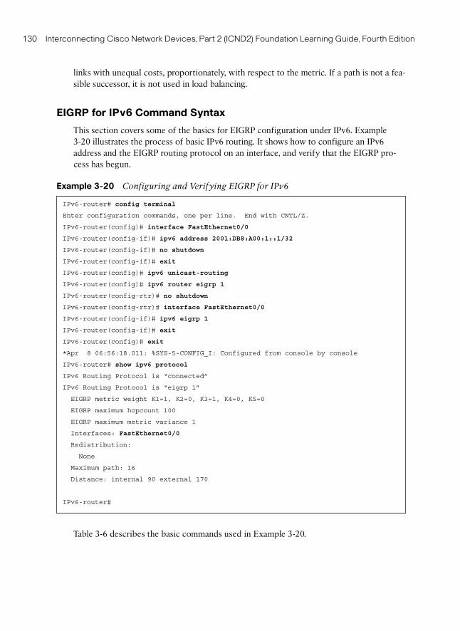
130 Interconnecting Cisco Network Devices, Part 2 (ICND2) Foundation Learning Guide, Fourth Edition
links with unequal costs, proportionately, with respect to the metric. If a path is not a fea-sible successor, it is not used in load balancing.
EIGRP for IPv6 Command Syntax
This section covers some of the basics for EIGRP configuration under IPv6. Example 3-20 illustrates the process of basic IPv6 routing. It shows how to configure an IPv6 address and the EIGRP routing protocol on an interface, and verify that the EIGRP pro-cess has begun.
Example 3-20 Configuring and Verifying EIGRP for IPv6
IPv6-router# config terminal
Enter configuration commands, one per line. End with CNTL/Z.
IPv6-router(config)# interface FastEthernet0/0
IPv6-router(config-if)# ipv6 address 2001:DB8:A00:1::1/32
IPv6-router(config-if)# no shutdown
IPv6-router(config-if)# exit
IPv6-router(config)# ipv6 unicast-routing
IPv6-router(config)# ipv6 router eigrp 1
IPv6-router(config-rtr)# no shutdown
IPv6-router(config-rtr)# interface FastEthernet0/0
IPv6-router(config-if)# ipv6 eigrp 1
IPv6-router(config-if)# exit
IPv6-router(config)# exit
*Apr 8 06:56:18.011: %SYS-5-CONFIG_I: Configured from console by console
IPv6-router# show ipv6 protocol
IPv6 Routing Protocol is “connected”
IPv6 Routing Protocol is “eigrp 1”
EIGRP metric weight K1=1, K2=0, K3=1, K4=0, K5=0
EIGRP maximum hopcount 100
EIGRP maximum metric variance 1
Interfaces: FastEthernet0/0
Redistribution:
None
Maximum path: 16
Distance: internal 90 external 170
IPv6-router#
Table 3-6 describes the basic commands used in Example 3-20 .