Embed Size (px)
Citation preview
ibm.com/redbooks
Implementing CICS Web Services
Nigel WilliamsGrant Ward Able
Paolo ChieregattiRobert Herman
Tommy JoergensenLuis Aused Lopez
Steve Wall
Configuring and securing Web services in CICS Transaction Server
Connecting CICS to a service integration bus
Enabling atomic Web services
Front cover

Implementing CICS Web Services
June 2006
International Technical Support Organization
SG24-7206-00
© Copyright International Business Machines Corporation 2006. All rights reserved.Note to U.S. Government Users Restricted Rights -- Use, duplication or disclosure restricted by GSA ADPSchedule Contract with IBM Corp.
First Edition (June 2006)
This edition applies to CICS Transaction Server Version 3.1.
Note: Before using this information and the product it supports, read the information in “Notices” on page ix.
Contents
Notices . . . . . . . . . . . . . . . . . . . . . . . . . . . . . . . . . . . . . . . . . . . . . . . . . . . . . . . ixTrademarks . . . . . . . . . . . . . . . . . . . . . . . . . . . . . . . . . . . . . . . . . . . . . . . . . . . . x
Preface . . . . . . . . . . . . . . . . . . . . . . . . . . . . . . . . . . . . . . . . . . . . . . . . . . . . . . . xiThe team that wrote this redbook. . . . . . . . . . . . . . . . . . . . . . . . . . . . . . . . . . . xiiBecome a published author . . . . . . . . . . . . . . . . . . . . . . . . . . . . . . . . . . . . . . . xivComments welcome. . . . . . . . . . . . . . . . . . . . . . . . . . . . . . . . . . . . . . . . . . . . . xv
Part 1. Introduction . . . . . . . . . . . . . . . . . . . . . . . . . . . . . . . . . . . . . . . . . . . . . . . . . . . . . . . . . . 1
Chapter 1. Overview of Web services . . . . . . . . . . . . . . . . . . . . . . . . . . . . . . 31.1 Introduction . . . . . . . . . . . . . . . . . . . . . . . . . . . . . . . . . . . . . . . . . . . . . . . . . 41.2 Service-oriented architecture . . . . . . . . . . . . . . . . . . . . . . . . . . . . . . . . . . . 4
1.2.1 Characteristics . . . . . . . . . . . . . . . . . . . . . . . . . . . . . . . . . . . . . . . . . . 51.2.2 Web services versus service-oriented architectures. . . . . . . . . . . . . . 6
1.3 Web services. . . . . . . . . . . . . . . . . . . . . . . . . . . . . . . . . . . . . . . . . . . . . . . . 71.3.1 Properties of a Web service . . . . . . . . . . . . . . . . . . . . . . . . . . . . . . . . 71.3.2 Core standards . . . . . . . . . . . . . . . . . . . . . . . . . . . . . . . . . . . . . . . . . . 81.3.3 Web Service Interoperability Basic Profile 1.0 . . . . . . . . . . . . . . . . . 101.3.4 Additional standards . . . . . . . . . . . . . . . . . . . . . . . . . . . . . . . . . . . . . 11
1.4 SOAP . . . . . . . . . . . . . . . . . . . . . . . . . . . . . . . . . . . . . . . . . . . . . . . . . . . . 121.4.1 The envelope . . . . . . . . . . . . . . . . . . . . . . . . . . . . . . . . . . . . . . . . . . 121.4.2 Communication styles . . . . . . . . . . . . . . . . . . . . . . . . . . . . . . . . . . . . 171.4.3 Encodings . . . . . . . . . . . . . . . . . . . . . . . . . . . . . . . . . . . . . . . . . . . . . 171.4.4 Messaging modes . . . . . . . . . . . . . . . . . . . . . . . . . . . . . . . . . . . . . . . 17
1.5 WSDL . . . . . . . . . . . . . . . . . . . . . . . . . . . . . . . . . . . . . . . . . . . . . . . . . . . . 181.5.1 WSDL Document . . . . . . . . . . . . . . . . . . . . . . . . . . . . . . . . . . . . . . . 191.5.2 WSDL document anatomy . . . . . . . . . . . . . . . . . . . . . . . . . . . . . . . . 191.5.3 WSDL definition . . . . . . . . . . . . . . . . . . . . . . . . . . . . . . . . . . . . . . . . 241.5.4 WSDL bindings . . . . . . . . . . . . . . . . . . . . . . . . . . . . . . . . . . . . . . . . . 30
1.6 Summary . . . . . . . . . . . . . . . . . . . . . . . . . . . . . . . . . . . . . . . . . . . . . . . . . . 31
Chapter 2. CICS support for Web services . . . . . . . . . . . . . . . . . . . . . . . . . 332.1 Overview . . . . . . . . . . . . . . . . . . . . . . . . . . . . . . . . . . . . . . . . . . . . . . . . . . 342.2 CICS as a service provider . . . . . . . . . . . . . . . . . . . . . . . . . . . . . . . . . . . . 37
2.2.1 Preparing to run a CICS application as a service provider . . . . . . . . 382.2.2 Processing the inbound service request . . . . . . . . . . . . . . . . . . . . . . 40
2.3 CICS as a service requester . . . . . . . . . . . . . . . . . . . . . . . . . . . . . . . . . . . 412.3.1 Preparing to run a CICS application as a service requester . . . . . . . 42
© Copyright IBM Corp. 2006. All rights reserved. iii
2.3.2 Processing the outbound service request . . . . . . . . . . . . . . . . . . . . . 442.3.3 Local optimization . . . . . . . . . . . . . . . . . . . . . . . . . . . . . . . . . . . . . . . 45
2.4 CICS resources for Web services . . . . . . . . . . . . . . . . . . . . . . . . . . . . . . . 472.4.1 URIMAP . . . . . . . . . . . . . . . . . . . . . . . . . . . . . . . . . . . . . . . . . . . . . . 472.4.2 PIPELINE . . . . . . . . . . . . . . . . . . . . . . . . . . . . . . . . . . . . . . . . . . . . . 492.4.3 WEBSERVICE . . . . . . . . . . . . . . . . . . . . . . . . . . . . . . . . . . . . . . . . . 532.4.4 TCPIPSERVICE . . . . . . . . . . . . . . . . . . . . . . . . . . . . . . . . . . . . . . . . 552.4.5 Resources checklist . . . . . . . . . . . . . . . . . . . . . . . . . . . . . . . . . . . . . 55
2.5 Message handlers . . . . . . . . . . . . . . . . . . . . . . . . . . . . . . . . . . . . . . . . . . . 572.5.1 SOAP message handlers . . . . . . . . . . . . . . . . . . . . . . . . . . . . . . . . . 572.5.2 Channels and containers . . . . . . . . . . . . . . . . . . . . . . . . . . . . . . . . . 59
2.6 Tools for developing CICS Web services . . . . . . . . . . . . . . . . . . . . . . . . . 612.6.1 CICS Web services assistant . . . . . . . . . . . . . . . . . . . . . . . . . . . . . . 622.6.2 Web services assistant utility programs . . . . . . . . . . . . . . . . . . . . . . 632.6.3 WebSphere Developer for zSeries . . . . . . . . . . . . . . . . . . . . . . . . . . 65
2.7 Catalog manager example application . . . . . . . . . . . . . . . . . . . . . . . . . . . 672.7.1 The base application . . . . . . . . . . . . . . . . . . . . . . . . . . . . . . . . . . . . . 672.7.2 Web services support for the catalog example application . . . . . . . . 69
Part 2. Web service configuration . . . . . . . . . . . . . . . . . . . . . . . . . . . . . . . . . . . . . . . . . . . . . 71
Chapter 3. Web services using HTTP . . . . . . . . . . . . . . . . . . . . . . . . . . . . . 733.1 Preparation . . . . . . . . . . . . . . . . . . . . . . . . . . . . . . . . . . . . . . . . . . . . . . . . 74
3.1.1 Software checklist . . . . . . . . . . . . . . . . . . . . . . . . . . . . . . . . . . . . . . . 753.1.2 Definition checklist . . . . . . . . . . . . . . . . . . . . . . . . . . . . . . . . . . . . . . 753.1.3 The sample application . . . . . . . . . . . . . . . . . . . . . . . . . . . . . . . . . . . 76
3.2 Configuring CICS as a service provider . . . . . . . . . . . . . . . . . . . . . . . . . . 763.2.1 Configuring code page support . . . . . . . . . . . . . . . . . . . . . . . . . . . . . 773.2.2 Configuring CICS . . . . . . . . . . . . . . . . . . . . . . . . . . . . . . . . . . . . . . . 773.2.3 Configuring WebSphere Application Server on Windows . . . . . . . . . 873.2.4 Testing the configuration. . . . . . . . . . . . . . . . . . . . . . . . . . . . . . . . . . 90
3.3 Configuring CICS as a service requester . . . . . . . . . . . . . . . . . . . . . . . . . 943.3.1 Configuring CICS . . . . . . . . . . . . . . . . . . . . . . . . . . . . . . . . . . . . . . . 953.3.2 Configuring WebSphere Application Server for z/OS . . . . . . . . . . . . 983.3.3 Testing the configuration. . . . . . . . . . . . . . . . . . . . . . . . . . . . . . . . . 100
3.4 Configuring for high availability . . . . . . . . . . . . . . . . . . . . . . . . . . . . . . . . 1013.4.1 TCP/IP load balancing . . . . . . . . . . . . . . . . . . . . . . . . . . . . . . . . . . 1023.4.2 High availability configuration . . . . . . . . . . . . . . . . . . . . . . . . . . . . . 1023.4.3 Routing inbound Web service requests . . . . . . . . . . . . . . . . . . . . . 102
3.5 Problem determination . . . . . . . . . . . . . . . . . . . . . . . . . . . . . . . . . . . . . . 1043.5.1 Error calling dispatch service - INVREQ . . . . . . . . . . . . . . . . . . . . . 104
Chapter 4. Web services using WebSphere MQ . . . . . . . . . . . . . . . . . . . . 1114.1 Preparation . . . . . . . . . . . . . . . . . . . . . . . . . . . . . . . . . . . . . . . . . . . . . . . 112
iv Implementing CICS Web Services
4.1.1 Software checklist . . . . . . . . . . . . . . . . . . . . . . . . . . . . . . . . . . . . . . 1134.1.2 Definition checklist . . . . . . . . . . . . . . . . . . . . . . . . . . . . . . . . . . . . . 113
4.2 WebSphere MQ configuration . . . . . . . . . . . . . . . . . . . . . . . . . . . . . . . . . 1144.2.1 Adding WebSphere MQ support to CICS . . . . . . . . . . . . . . . . . . . . 1144.2.2 Defining the queues . . . . . . . . . . . . . . . . . . . . . . . . . . . . . . . . . . . . 1154.2.3 Defining the trigger process . . . . . . . . . . . . . . . . . . . . . . . . . . . . . . 116
4.3 Configuring CICS as a service provider using WMQ . . . . . . . . . . . . . . . 1164.3.1 Configuring the service provider pipeline . . . . . . . . . . . . . . . . . . . . 117
4.4 Configuring CICS as service requester using WMQ . . . . . . . . . . . . . . . . 1214.4.1 Configuring the Catalog application . . . . . . . . . . . . . . . . . . . . . . . . 1224.4.2 Configuring WebSphere Application Server on Windows . . . . . . . . 124
4.5 Testing the WMQ configuration. . . . . . . . . . . . . . . . . . . . . . . . . . . . . . . . 1244.6 High availability with WMQ . . . . . . . . . . . . . . . . . . . . . . . . . . . . . . . . . . . 126
Chapter 5. Connecting CICS to the service integration bus . . . . . . . . . . 1295.1 Overview of the service integration bus . . . . . . . . . . . . . . . . . . . . . . . . . 130
5.1.1 Why you would connect CICS to a bus. . . . . . . . . . . . . . . . . . . . . . 1315.2 Preparation . . . . . . . . . . . . . . . . . . . . . . . . . . . . . . . . . . . . . . . . . . . . . . . 132
5.2.1 Software checklist . . . . . . . . . . . . . . . . . . . . . . . . . . . . . . . . . . . . . . 1345.2.2 Definition checklist . . . . . . . . . . . . . . . . . . . . . . . . . . . . . . . . . . . . . 134
5.3 Configuring CICS for a gateway service . . . . . . . . . . . . . . . . . . . . . . . . . 1355.3.1 Updating the CICS-supplied sample WSDL file . . . . . . . . . . . . . . . 1355.3.2 Creating a URIMAP for the WSDL file . . . . . . . . . . . . . . . . . . . . . . 1355.3.3 Testing the retrieval of the WSDL file from a Web browser . . . . . . 137
5.4 Creating a gateway service on the bus . . . . . . . . . . . . . . . . . . . . . . . . . . 1395.4.1 Identifying the bus to be used . . . . . . . . . . . . . . . . . . . . . . . . . . . . . 1395.4.2 Creating a Web services gateway instance . . . . . . . . . . . . . . . . . . 1405.4.3 Creating a gateway service. . . . . . . . . . . . . . . . . . . . . . . . . . . . . . . 141
5.5 Testing the CICS gateway service . . . . . . . . . . . . . . . . . . . . . . . . . . . . . 1455.5.1 Publish the bus-generated WSDL. . . . . . . . . . . . . . . . . . . . . . . . . . 1455.5.2 Configuring the catalog manager J2EE application . . . . . . . . . . . . 1465.5.3 Invoking the gateway service . . . . . . . . . . . . . . . . . . . . . . . . . . . . . 147
Part 3. Security management. . . . . . . . . . . . . . . . . . . . . . . . . . . . . . . . . . . . . . . . . . . . . . . . 149
Chapter 6. Securing Web services. . . . . . . . . . . . . . . . . . . . . . . . . . . . . . . 1516.1 Security challenges . . . . . . . . . . . . . . . . . . . . . . . . . . . . . . . . . . . . . . . . . 152
6.1.1 The meaning of security . . . . . . . . . . . . . . . . . . . . . . . . . . . . . . . . . 1536.2 Traditional CICS security. . . . . . . . . . . . . . . . . . . . . . . . . . . . . . . . . . . . . 155
6.2.1 CICS user IDs . . . . . . . . . . . . . . . . . . . . . . . . . . . . . . . . . . . . . . . . . 1566.3 Transport security . . . . . . . . . . . . . . . . . . . . . . . . . . . . . . . . . . . . . . . . . . 157
6.3.1 HTTP transport . . . . . . . . . . . . . . . . . . . . . . . . . . . . . . . . . . . . . . . . 1576.3.2 WebSphere MQ Security . . . . . . . . . . . . . . . . . . . . . . . . . . . . . . . . 162
6.4 SOAP message security . . . . . . . . . . . . . . . . . . . . . . . . . . . . . . . . . . . . . 164
Contents v
6.4.1 Example of WS-Security . . . . . . . . . . . . . . . . . . . . . . . . . . . . . . . . . 1666.5 Comparison of transport versus SOAP message security . . . . . . . . . . . 172
6.5.1 Intermediate gateways . . . . . . . . . . . . . . . . . . . . . . . . . . . . . . . . . . 173
Chapter 7. Security scenarios . . . . . . . . . . . . . . . . . . . . . . . . . . . . . . . . . . 1777.1 Preparation . . . . . . . . . . . . . . . . . . . . . . . . . . . . . . . . . . . . . . . . . . . . . . . 178
7.1.1 Software checklist . . . . . . . . . . . . . . . . . . . . . . . . . . . . . . . . . . . . . . 1787.1.2 Definition checklist . . . . . . . . . . . . . . . . . . . . . . . . . . . . . . . . . . . . . 179
7.2 Basic security configuration. . . . . . . . . . . . . . . . . . . . . . . . . . . . . . . . . . . 1807.2.1 Setting up basic security configuration . . . . . . . . . . . . . . . . . . . . . . 1817.2.2 Testing the basic security configuration . . . . . . . . . . . . . . . . . . . . . 181
7.3 Setting the user ID on a URIMAP definition . . . . . . . . . . . . . . . . . . . . . . 1827.3.1 Defining the URIMAP . . . . . . . . . . . . . . . . . . . . . . . . . . . . . . . . . . . 1837.3.2 Permitting access to user ID CICSNW . . . . . . . . . . . . . . . . . . . . . . 1867.3.3 Testing user ID on URIMAP resource definition . . . . . . . . . . . . . . . 186
7.4 Enabling SOAP message security with HTTP. . . . . . . . . . . . . . . . . . . . . 1877.4.1 Configuring the service requester . . . . . . . . . . . . . . . . . . . . . . . . . . 1887.4.2 Configuring CICS . . . . . . . . . . . . . . . . . . . . . . . . . . . . . . . . . . . . . . 1957.4.3 Testing SOAP message security . . . . . . . . . . . . . . . . . . . . . . . . . . 2007.4.4 SOAP fault messages . . . . . . . . . . . . . . . . . . . . . . . . . . . . . . . . . . . 201
7.5 Enabling SSL/TLS . . . . . . . . . . . . . . . . . . . . . . . . . . . . . . . . . . . . . . . . . . 2037.5.1 Creating a key ring and certificates on z/OS for CICS . . . . . . . . . . 2047.5.2 Enabling an SSL/TLS connection from WebSphere . . . . . . . . . . . . 2067.5.3 Configuring CICS support for SSL/TLS. . . . . . . . . . . . . . . . . . . . . . 2117.5.4 Testing SSL/TLS . . . . . . . . . . . . . . . . . . . . . . . . . . . . . . . . . . . . . . . 212
7.6 Enabling SOAP message security with WMQ. . . . . . . . . . . . . . . . . . . . . 2147.6.1 Configuring CICS to use WMQ . . . . . . . . . . . . . . . . . . . . . . . . . . . . 2167.6.2 Configuring the service requester . . . . . . . . . . . . . . . . . . . . . . . . . . 2177.6.3 Header processing program . . . . . . . . . . . . . . . . . . . . . . . . . . . . . . 2177.6.4 Configuring the service provider . . . . . . . . . . . . . . . . . . . . . . . . . . . 2187.6.5 Configuring WebSphere MQ for security . . . . . . . . . . . . . . . . . . . . 2207.6.6 Testing security with WMQ . . . . . . . . . . . . . . . . . . . . . . . . . . . . . . . 221
Part 4. Transaction management. . . . . . . . . . . . . . . . . . . . . . . . . . . . . . . . . . . . . . . . . . . . . 225
Chapter 8. Introduction to Web services: Atomic transactions . . . . . . . 2278.1 Beginner’s guide to atomic transactions . . . . . . . . . . . . . . . . . . . . . . . . . 228
8.1.1 What is a classic transaction. . . . . . . . . . . . . . . . . . . . . . . . . . . . . . 2298.1.2 Mapping from classic transactions to WS-Atomic Transaction . . . . 233
8.2 WS-Addressing . . . . . . . . . . . . . . . . . . . . . . . . . . . . . . . . . . . . . . . . . . . . 2368.2.1 Endpoint references . . . . . . . . . . . . . . . . . . . . . . . . . . . . . . . . . . . . 2378.2.2 Message information headers. . . . . . . . . . . . . . . . . . . . . . . . . . . . . 2408.2.3 SOAP binding for endpoint references . . . . . . . . . . . . . . . . . . . . . . 242
8.3 WS-Coordination . . . . . . . . . . . . . . . . . . . . . . . . . . . . . . . . . . . . . . . . . . . 243
vi Implementing CICS Web Services
8.3.1 Coordination service . . . . . . . . . . . . . . . . . . . . . . . . . . . . . . . . . . . . 2448.3.2 CreateCoordinationContext. . . . . . . . . . . . . . . . . . . . . . . . . . . . . . . 2458.3.3 CreateCoordinationContextResponse . . . . . . . . . . . . . . . . . . . . . . 2478.3.4 Register. . . . . . . . . . . . . . . . . . . . . . . . . . . . . . . . . . . . . . . . . . . . . . 2508.3.5 RegisterResponse. . . . . . . . . . . . . . . . . . . . . . . . . . . . . . . . . . . . . . 2528.3.6 Two applications with their own coordinators . . . . . . . . . . . . . . . . . 2528.3.7 Addressing requirements for WS-Coordination message types . . . 254
8.4 WS-Atomic Transaction. . . . . . . . . . . . . . . . . . . . . . . . . . . . . . . . . . . . . . 2548.4.1 Completion protocol . . . . . . . . . . . . . . . . . . . . . . . . . . . . . . . . . . . . 2568.4.2 Two-Phase Commit protocol . . . . . . . . . . . . . . . . . . . . . . . . . . . . . . 2578.4.3 Two applications with their own coordinators (continued). . . . . . . . 2608.4.4 Addressing requirements for WS-AT message types . . . . . . . . . . . 2618.4.5 CICS TS V3.1 and resynchronization processing . . . . . . . . . . . . . . 261
Chapter 9. Enabling atomic transactions . . . . . . . . . . . . . . . . . . . . . . . . . 2659.1 Enabling atomic transactions in CICS . . . . . . . . . . . . . . . . . . . . . . . . . . . 266
9.1.1 CICS to CICS configuration . . . . . . . . . . . . . . . . . . . . . . . . . . . . . . 2669.1.2 More elaborate CICS to CICS configuration . . . . . . . . . . . . . . . . . . 276
9.2 Enabling atomic transactions in WebSphere. . . . . . . . . . . . . . . . . . . . . . 278
Chapter 10. Transaction scenarios . . . . . . . . . . . . . . . . . . . . . . . . . . . . . . 28110.1 Introduction to our scenarios . . . . . . . . . . . . . . . . . . . . . . . . . . . . . . . . . 282
10.1.1 Software checklist . . . . . . . . . . . . . . . . . . . . . . . . . . . . . . . . . . . . . 28310.1.2 Definition checklist . . . . . . . . . . . . . . . . . . . . . . . . . . . . . . . . . . . . 283
10.2 The simple atomic transaction scenario . . . . . . . . . . . . . . . . . . . . . . . . 28510.2.1 Setting up CICS for the simple scenario . . . . . . . . . . . . . . . . . . . . 28710.2.2 Creating the AtomicClient and ITSO.ORDER table . . . . . . . . . . . 29110.2.3 Testing the simple scenario . . . . . . . . . . . . . . . . . . . . . . . . . . . . . 307
10.3 The daisy chain atomic transaction scenario . . . . . . . . . . . . . . . . . . . . 32810.3.1 Setting up CICS for the daisy chain scenario . . . . . . . . . . . . . . . . 33010.3.2 Creating DispatchOrderAtomic and the ITSO.DISPATCH table . . 33210.3.3 Testing the daisy chain scenario. . . . . . . . . . . . . . . . . . . . . . . . . . 335
10.4 Transaction scenario summary . . . . . . . . . . . . . . . . . . . . . . . . . . . . . . . 342
Part 5. Appendixes . . . . . . . . . . . . . . . . . . . . . . . . . . . . . . . . . . . . . . . . . . . . . . . . . . . . . . . . 343
Appendix A. Sample handler programs . . . . . . . . . . . . . . . . . . . . . . . . . . 345A.1 Sample message handler program - CIWSMSGH . . . . . . . . . . . . . . . . . 346A.2 Sample header processing program - CIWSSECH . . . . . . . . . . . . . . . . 351A.3 Sample handler program - SNIFFER . . . . . . . . . . . . . . . . . . . . . . . . . . . 357A.4 Sample XML parser program - MYPARSER . . . . . . . . . . . . . . . . . . . . . 368A.5 Sample header processing program - CIWSSECR . . . . . . . . . . . . . . . . 373A.6 Sample header processing program - CIWSSECS . . . . . . . . . . . . . . . . 380A.7 Sample header processing program - WSATHND . . . . . . . . . . . . . . . . . 385
Contents vii
Appendix B. Additional material . . . . . . . . . . . . . . . . . . . . . . . . . . . . . . . . 391Locating the Web material . . . . . . . . . . . . . . . . . . . . . . . . . . . . . . . . . . . . . . . 391Using the Web material . . . . . . . . . . . . . . . . . . . . . . . . . . . . . . . . . . . . . . . . . 391
System requirements for downloading the Web material . . . . . . . . . . . . . 392How to use the material . . . . . . . . . . . . . . . . . . . . . . . . . . . . . . . . . . . . . . 392
Abbreviations and acronyms . . . . . . . . . . . . . . . . . . . . . . . . . . . . . . . . . . . 395
Related publications . . . . . . . . . . . . . . . . . . . . . . . . . . . . . . . . . . . . . . . . . . 397IBM Redbooks . . . . . . . . . . . . . . . . . . . . . . . . . . . . . . . . . . . . . . . . . . . . . . . . 397Other publications . . . . . . . . . . . . . . . . . . . . . . . . . . . . . . . . . . . . . . . . . . . . . 397Online resources . . . . . . . . . . . . . . . . . . . . . . . . . . . . . . . . . . . . . . . . . . . . . . 398How to get IBM Redbooks . . . . . . . . . . . . . . . . . . . . . . . . . . . . . . . . . . . . . . . 398Help from IBM . . . . . . . . . . . . . . . . . . . . . . . . . . . . . . . . . . . . . . . . . . . . . . . . 398
Index . . . . . . . . . . . . . . . . . . . . . . . . . . . . . . . . . . . . . . . . . . . . . . . . . . . . . . . 399
viii Implementing CICS Web Services
Notices
This information was developed for products and services offered in the U.S.A.
IBM may not offer the products, services, or features discussed in this document in other countries. Consult your local IBM representative for information on the products and services currently available in your area. Any reference to an IBM product, program, or service is not intended to state or imply that only that IBM product, program, or service may be used. Any functionally equivalent product, program, or service that does not infringe any IBM intellectual property right may be used instead. However, it is the user's responsibility to evaluate and verify the operation of any non-IBM product, program, or service.
IBM may have patents or pending patent applications covering subject matter described in this document. The furnishing of this document does not give you any license to these patents. You can send license inquiries, in writing, to: IBM Director of Licensing, IBM Corporation, North Castle Drive, Armonk, NY 10504-1785 U.S.A.
The following paragraph does not apply to the United Kingdom or any other country where such provisions are inconsistent with local law: INTERNATIONAL BUSINESS MACHINES CORPORATION PROVIDES THIS PUBLICATION "AS IS" WITHOUT WARRANTY OF ANY KIND, EITHER EXPRESS OR IMPLIED, INCLUDING, BUT NOT LIMITED TO, THE IMPLIED WARRANTIES OF NON-INFRINGEMENT, MERCHANTABILITY OR FITNESS FOR A PARTICULAR PURPOSE. Some states do not allow disclaimer of express or implied warranties in certain transactions, therefore, this statement may not apply to you.
This information could include technical inaccuracies or typographical errors. Changes are periodically made to the information herein; these changes will be incorporated in new editions of the publication. IBM may make improvements and/or changes in the product(s) and/or the program(s) described in this publication at any time without notice.
Any references in this information to non-IBM Web sites are provided for convenience only and do not in any manner serve as an endorsement of those Web sites. The materials at those Web sites are not part of the materials for this IBM product and use of those Web sites is at your own risk.
IBM may use or distribute any of the information you supply in any way it believes appropriate without incurring any obligation to you.
Information concerning non-IBM products was obtained from the suppliers of those products, their published announcements or other publicly available sources. IBM has not tested those products and cannot confirm the accuracy of performance, compatibility or any other claims related to non-IBM products. Questions on the capabilities of non-IBM products should be addressed to the suppliers of those products.
This information contains examples of data and reports used in daily business operations. To illustrate them as completely as possible, the examples include the names of individuals, companies, brands, and products. All of these names are fictitious and any similarity to the names and addresses used by an actual business enterprise is entirely coincidental.
COPYRIGHT LICENSE:
This information contains sample application programs in source language, which illustrate programming techniques on various operating platforms. You may copy, modify, and distribute these sample programs in any form without payment to IBM, for the purposes of developing, using, marketing or distributing application programs conforming to the application programming interface for the operating platform for which the sample programs are written. These examples have not been thoroughly tested under all conditions. IBM, therefore, cannot guarantee or imply reliability, serviceability, or function of these programs.
© Copyright IBM Corp. 2006. All rights reserved. ix
TrademarksThe following terms are trademarks of the International Business Machines Corporation in the United States, other countries, or both:
Eserver®Eserver®Redbooks (logo) ™developerWorks®iSeries™z/OS®zSeries®Candle®
CICS®CICSPlex®DB2®IBM®IMS™MQSeries®MVS™OS/390®
Parallel Sysplex®Rational®Redbooks™RACF®Tivoli®VTAM®WebSphere®
The following terms are trademarks of other companies:
Enterprise JavaBeans, EJB, Java, Java Naming and Directory Interface, JavaBeans, JavaServer, JDBC, JDK, JSP, JVM, J2EE, Sun, Sun Microsystems, and all Java-based trademarks are trademarks of Sun Microsystems, Inc. in the United States, other countries, or both.
Internet Explorer, Microsoft, Windows, and the Windows logo are trademarks of Microsoft Corporation in the United States, other countries, or both.
Intel, Pentium, Intel logo, Intel Inside logo, and Intel Centrino logo are trademarks or registered trademarks of Intel Corporation or its subsidiaries in the United States, other countries, or both.
UNIX is a registered trademark of The Open Group in the United States and other countries.
Linux is a trademark of Linus Torvalds in the United States, other countries, or both.
Other company, product, or service names may be trademarks or service marks of others.
x Implementing CICS
Preface
Today, more and more companies are embracing the principles of on demand business by integrating business processes end to end across the company and with key partners, enabling them to respond flexibly and rapidly to new circumstances. The move to an on demand business environment requires technical transformation, moving the focus from discrete applications to connected, interdependent information technology components.
Open standards such as Web services enable these components to be hosted in the environments most appropriate to their requirements, while still being able to interact easily — independent of hardware, run-time environment, and programming language.
The Web services support in CICS® Transaction Server Version 3.1 enables your CICS programs to be Web service providers and requesters. CICS supports a number of specifications including SOAP Version 1.1 and Version 1.2, and Web services distributed transactions (WS-Atomic Transaction).
This IBM® Redbook describes how to configure CICS Web services support for HTTP-based and WebSphere® MQ-based solutions, and demonstrates how Web services can be used to integrate J2EE™ applications running in WebSphere Application Server with COBOL programs running in CICS.
It begins with an overview of Web services standards and the Web services support provided by CICS TS V3.1. Complete details for configuring CICS Web services using both HTTP and WebSphere MQ are provided next, along with the steps for using Web services to connect to CICS from a service integration bus. The book then shows how CICS Web services can be secured using a combination of Web Services Security (WS-Security) and transport-level security mechanisms such as SSL/TLS. Finally, it demonstrates how atomic Web services transactions can be configured to allow WebSphere and CICS resource updates to be synchronized.
This book concentrates on implementation specifics such as security, transactions, and availability. The companion redbook Developing CICS Web Services (SG24-7126) presents detailed information on developing CICS Web services.
© Copyright IBM Corp. 2006. All rights reserved. xi
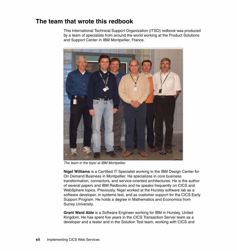
The team that wrote this redbookThis International Technical Support Organization (ITSO) redbook was produced by a team of specialists from around the world working at the Product Solutions and Support Center in IBM Montpellier, France.
The team in the foyer at IBM Montpellier
Nigel Williams is a Certified IT Specialist working in the IBM Design Center for On Demand Business in Montpellier. He specializes in core business transformation, connectors, and service-oriented architectures. He is the author of several papers and IBM Redbooks and he speaks frequently on CICS and WebSphere topics. Previously, Nigel worked at the Hursley software lab as a software developer, in systems test, and as customer support for the CICS Early Support Program. He holds a degree in Mathematics and Economics from Surrey University.
Grant Ward Able is a Software Engineer working for IBM in Hursley, United Kingdom. He has spent five years in the CICS Transaction Server team as a developer and a tester and in the Solution Test team, working with CICS and
xii Implementing CICS Web Services
WebSphere. Previously, Grant worked for 15 years as a CICS systems programmer. He currently works in the CICS Service Flow runtime team.
Paolo Chieregatti is an IT specialist working for IBM Software Group in Italy. He has 20 years of experience in IT working mainly on IBM mainframes. His areas of expertise include CICS, WebSphere MQ, WebSphere Application Server, and legacy application transformation and integration. He speaks frequently on CICS and WebSphere topics. Before joining IBM, Paolo worked for the Candle® Corporation. He has worked as a CICS systems programmer and project manager.
Robert Herman is a Senior IT Specialist, Systems Management Integrator with IBM Global Services in Endicott, New York. He has 27 years of experience supporting CICS and related products for a variety of IBM internal and external customer accounts. Bob has worked on several IBM Redbooks including Enterprise JavaBeans for z/OS and OS/390 CICS Transaction Server V2.2, SG24-6284. He holds a Bachelor’s degree in mathematics from Grinnell College and a Master’s degree in computer science from Iowa State University.
Tommy Joergensen is a Senior IT Specialist working for IBM Global Services in IBM Denmark. He has more than 25 years of experience working in CICS technical support, including three years at IBM Hursley. In recent years he has delivered services at large accounts in Denmark for both the CICS and WebSphere products. Tommy is the IBM representative in the CICS working group of the Nordic Share Guide organization.
Luis Aused Lopez is an IT Specialist for IBM Global Services in Spain, working in Business Consulting Services (BCS) in the travel and transportation sectors. As an assignee he works in the zSeries® Benchmark Center in IBM Montpellier. He has worked for IBM for over ten years. During this time, he has developed several J2EE applications for WebSphere running on different platforms including zSeries, iSeries™, Linux® and Windows®. His areas of expertise include application development, WebSphere, Java™ performance, DB2® and eTicketing. He is an author of several IBM Redbooks™ and holds a degree in Physics from Complutense University, Madrid, Spain.
Steve Wall (missing from the photograph) is an IT specialist working in the zSeries Benchmark Center. He worked for the CICS Transaction Server Development organization at Hursley, United Kingdom, for over 20 years before joining the PSSC. Steve has a degree in Linguistic and International Studies from the University of Surrey. He has written and taught extensively about CICS e-business enablement using CICS Web Support and the CICS Transaction Gateway.
Preface xiii
Thanks to the following people for their contributions to this project:
Phil Hanson and Mark Cocker of IBM Hursley for supporting this project.
Pascal Tillard for his support setting up the WebSphere Application Server for z/OS® environment and for assisting with the setup of the service integration bus.
Mike Brooks of IBM Hursley for explaining the CICS WS-AtomicTransaction support and making direct contributions to Part 4 of this book.
Ken Ray of IBM UK for his support in setting up WebSphere MQ.
Ian Noble and Oliver Fenton of IBM Hursley for supplying sample programs.
Mike Adams, Fraser Bohm, Peter Havercan and Ian Mitchell of IBM Hursley, Derek Ho and Peter Birk from IBM Austin, and Jeff Oestrich of IBM Raleigh for supplying technical advice during the residency.
The team that wrote the Redbook Developing for CICS Web Services (SG24-7126), Chris Rayns, Jim Hollingsworth, Chris Backhouse, David Evans, and Isabel Arnold.
Philippe Richard of IBM Montpellier for providing excellent systems support.
Ella Buslovich of the ITSO Poughkeepsie for help with the graphics.
The following people for the significant amount of time that they have spent reviewing and for their detailed review comments: Cheryll Clark of IBM Australia, Alan Roessle of IBM Montpellier, Phil Wakelin and Robert Harris of IBM Hursley.
Become a published authorJoin us for a two- to six-week residency program! Help write an IBM Redbook dealing with specific products or solutions, while getting hands-on experience with leading-edge technologies. You'll team with IBM technical professionals, Business Partners and/or customers.
Your efforts will help increase product acceptance and customer satisfaction. As a bonus, you'll develop a network of contacts in IBM development labs, and increase your productivity and marketability.
Find out more about the residency program, browse the residency index, and apply online at:
ibm.com/redbooks/residencies.html
xiv Implementing CICS Web Services
Comments welcomeYour comments are important to us!
We want our Redbooks to be as helpful as possible. Send us your comments about this or other Redbooks in one of the following ways:
� Use the online Contact us review redbook form found at:
ibm.com/redbooks
� Send your comments in an e-mail to:
� Mail your comments to:
IBM Corporation, International Technical Support OrganizationDept. HYJ; HYJ Mail Station P0992455 South RoadPoughkeepsie, NY 12601-5400
Preface xv

xvi Implementing CICS Web Services
Part 1 Introduction
In this part we give a broad overview of different Web services technologies and then explain how to use Web services in CICS Transaction Server V3.1.
Part 1
© Copyright IBM Corp. 2006. All rights reserved. 1

2 Implementing CICS Web Services
Chapter 1. Overview of Web services
This chapter focuses on some of the architectural concepts that must be considered on a Web services project. We define and discuss service-oriented architecture (SOA) and the relationship between SOAs and Web services.
We then take a closer look at Web services, a technology that enables you to invoke applications using Internet protocols and standards. The technology is called “Web services” because it integrates services (applications) using Web technologies (the Internet and its standards).
1
© Copyright IBM Corp. 2006. All rights reserved. 3
1.1 Introduction
There is a strong trend for companies to integrate existing systems to implement IT support for business processes that cover the entire business cycle. Today, interactions already exist using a variety of schemes that range from very rigid point-to-point electronic data interchange (EDI) interactions to open Web auctions. Many companies have already made some of their IT systems available to all of their divisions and departments, or even their customers or partners on the Web. However, techniques for collaboration vary from one case to another and are thus proprietary solutions; systems often collaborate without any vision or architecture.
Thus, there is an increasing demand for technologies that support the connecting or sharing of resources and data in a very flexible and standardized manner. When technologies and implementations vary across companies and even within divisions or departments, unified business processes cannot be smoothly supported by technology. Integration has been developed only between units that are already aware of each other and that use the same static applications.
Furthermore, there is a need to structure large applications into building blocks in order to use well-defined components within different business processes. A shift towards a service-oriented approach will not only standardize interaction, but also allow for more flexibility in the process. The complete value chain within a company is divided into small modular functional units, or services. A service-oriented architecture thus has to focus on how services are described and organized to support their dynamic, automated discovery and use.
Companies and their sub-units should be able to easily provide services. Other business units can use these services to implement their business processes. This integration can be ideally performed during the runtime of the system, not just at the design time.
1.2 Service-oriented architecture
This section is a short introduction to the key concepts of a service-oriented architecture. The architecture makes no statements about the infrastructure or protocols it uses. Therefore, you can implement a service-oriented architecture using technologies other than Web technologies.
4 Implementing CICS Web Services
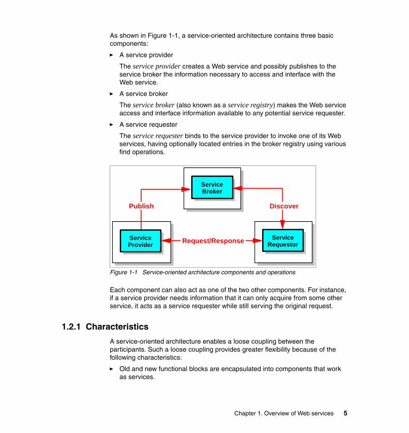
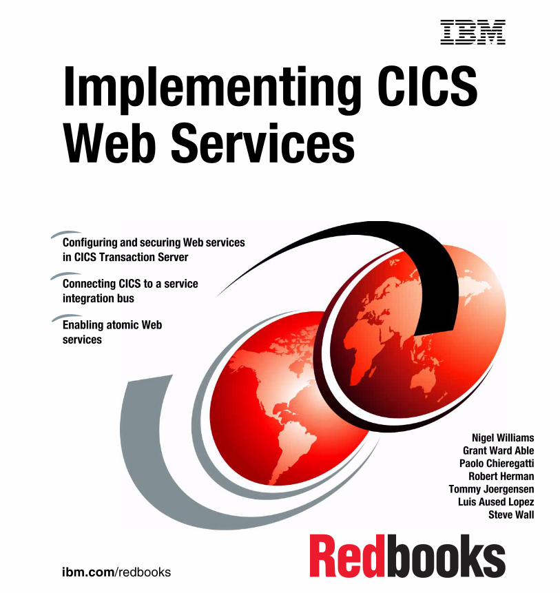
As shown in Figure 1-1, a service-oriented architecture contains three basic components:
� A service provider
The service provider creates a Web service and possibly publishes to the service broker the information necessary to access and interface with the Web service.
� A service broker
The service broker (also known as a service registry) makes the Web service access and interface information available to any potential service requester.
� A service requester
The service requester binds to the service provider to invoke one of its Web services, having optionally located entries in the broker registry using various find operations.
Figure 1-1 Service-oriented architecture components and operations
Each component can also act as one of the two other components. For instance, if a service provider needs information that it can only acquire from some other service, it acts as a service requester while still serving the original request.
1.2.1 Characteristics
A service-oriented architecture enables a loose coupling between the participants. Such a loose coupling provides greater flexibility because of the following characteristics:
� Old and new functional blocks are encapsulated into components that work as services.
ServiceBroker
ServiceProvider
ServiceRequestor
Publish Discover
Request/Response
Chapter 1. Overview of Web services 5
� Functional components and their interfaces are separated. Therefore, new interfaces can be plugged in more easily.
� Within complex applications, the control of business processes can be isolated. A business rules engine can be incorporated to control the workflow of a defined business process. Depending on the state of the workflow, the engine calls the respective services.
1.2.2 Web services versus service-oriented architectures
A service-oriented architecture has been used under various guises for many years. It can be (and has been) implemented using a number of different distributed computing technologies, such as CORBA and messaging middleware. The effectiveness of service-oriented architectures in the past has always been limited by the ability of the underlying technology to interoperate across the enterprise.
Web services technology is an ideal technology choice for implementing a service-oriented architecture because:
� Web services are based on standards, and standards promote interoperability. Interoperability is a key business advantage within the enterprise and is crucial in B2B scenarios.
� Web services are widely supported across the industry. For the very first time, all major vendors are recognizing and providing support for Web services. The Web Services Interoperability Organization (WS-I) is an organization that promotes open interoperability between Web services regardless of the platforms, operating systems, or programming languages used.
� Web services are platform and language neutral. There is no bias for or against a particular hardware or software platform. Web services can be implemented in any programming language or toolset. This is important because there will be continued industry support for the development of standards and interoperability between vendor implementations.
� This technology provides a migration path to gradually enable existing business functions as Web services.
� This technology supports synchronous and asynchronous, RPC-based, and complex message-oriented exchange patterns.
Conversely, there are many Web services implementations that are not a service-oriented architecture. For example, the use of Web services to connect two heterogeneous systems directly together is not an SOA. These uses of Web services solve real problems and provide significant value on their own. They may form the starting point of an SOA.
6 Implementing CICS Web Services
In general, an SOA has to be implemented at an enterprise or organizational level in order to achieve many of the benefits.
For more information about the relationship between Web services and service-oriented architectures refer to the IBM Redbook Patterns: Service-Oriented Architecture and Web Services, SG24-6303.
1.3 Web services
If we had to describe Web services using just one sentence, we would use the following:
Web services are self-contained, modular applications that can be described, published, located, and invoked over a network.
Web services perform encapsulated business functions, ranging from simple request-reply to full business process interactions. These services can be new applications or wrapped around existing business functions to make them network-enabled. Services can rely on other services to achieve their goals.
The World Wide Web Consortium (W3C) Services Architecture Working Group defines a Web service as follows:
A Web service is a software system designed to support interoperable machine-to-machine interaction over a network. It has an interface described in a machine-processable format (specifically WSDL). Other systems interact with the Web service in a manner prescribed by its description using SOAP messages, typically conveyed using HTTP with an XML serialization in conjunction with other Web-related standards.
It is important to note from this definition that a Web service is not constrained to use SOAP over HTTP/S as the transport mechanism. Web services are equally at home in the messaging world.
1.3.1 Properties of a Web service
All Web services share the following properties:
� Web services are self-contained.
On the client side, no additional software is required. A programming language with XML and HTTP client support is enough to get you started. On the server side, merely an HTTP server and a SOAP server are required.
Chapter 1. Overview of Web services 7
� Web services are self-describing.
A Web Service Description Language (WSDL) file provides all the information you need to implement a Web service as a provider or to invoke a Web service as a requester.
� Web services can be published, located, and invoked across the Web.
The service requester uses established lightweight Internet standards such as HTTP to invoke the service provider. It leverages the existing infrastructure.
� Web services are modular.
Simple Web services can be aggregated to form more complex ones, either using workflow techniques or by calling lower-layer Web services from a Web service implementation. Web services can be chained together to perform higher-level business functions. This shortens development time and enables best-of-breed implementations.
� Web services are language-independent and interoperable.
The client and server can be implemented in different environments. Any language can be used to implement Web service clients and servers.
� Web services are inherently open and standards-based.
XML and HTTP are the major technical foundation for Web services. A large part of the Web service technology has been built using open source projects. Therefore, vendor independence and interoperability are realistic goals.
� Web services are loosely coupled.
A service requester has to know the interface to a Web service but not the details of how it has been implemented.
� Web services provide programmatic access.
The approach provides no graphical user interface; it operates at the code level.
� Web services provide the ability to wrap existing applications.
Existing applications can easily be integrated into the service-oriented architecture by implementing a Web service as an interface to the application.
1.3.2 Core standards
Web services are built upon four core standards: XML, SOAP, WSDL, and UDDI. Each standard is described briefly in this section.
8 Implementing CICS Web Services
Extensible Markup Language (XML)XML is the foundation of Web services. However, since much information has already been written about XML, we do not describe it in this document. You can find information about XML at:
http://www.w3.org/XML/
SOAPOriginally proposed by Microsoft®, SOAP was designed to be a simple and extensible specification for the exchange of structured, XML-based information in a decentralized, distributed environment. As such, it represents the main means of communication between the three actors in an SOA: the service provider, the service requester, and the service broker. A group of companies, including IBM, submitted SOAP to the W3C for consideration by its XML Protocol Working Group. There are currently two versions of SOAP: Version 1.1 and Version 1.2.
The SOAP 1.1 specification contains three parts:
� An envelope that defines a framework for describing message content and processing instructions. Each SOAP message consists of an envelope that contains an arbitrary number of headers and one body that carries the payload. SOAP messages might contain faults; faults report failures or unexpected conditions.
� A set of encoding rules for expressing instances of application-defined data types.
� A convention for representing remote procedure calls and responses.
A SOAP message is, in principle, independent of the transport protocol which is used, and can, therefore, potentially be used with a variety of protocols such as HTTP, JMS, SMTP, or FTP. Right now, the most common way of exchanging SOAP messages is through HTTP.
The way SOAP applications communicate when exchanging messages is often referred to as the message exchange pattern (MEP). The communication can be either one-way messaging, where the SOAP message only goes in one direction, or two-way messaging, where the receiver is expected to send back a reply.
Due to the characteristics of SOAP, it does not matter what technology is used to implement the client, as long as the client can issue XML messages. Similarly, the service can be implemented in any language, as long as it can process XML messages.
We discuss SOAP in more detail in “SOAP” on page 12.
Chapter 1. Overview of Web services 9

Web Services Description Language (WSDL)This standard describes Web services as abstract service endpoints that operate on messages. Both the operations and the messages are defined in an abstract manner, while the actual protocol used to carry the message and the endpoint’s address are concrete.
WSDL is not bound to any particular protocol or network service. It can be extended to support many different message formats and network protocols. However, because Web services are mainly implemented using SOAP and HTTP, the corresponding bindings are part of this standard.
As of this writing, WSDL 1.1 is in use and WSDL 2.0 is a working draft. We discuss WSDL in more detail in “WSDL” on page 18.
Universal Description, Discovery, and Integration (UDDI)The Universal Description, Discovery, and Integration standard defines a means to publish and to discover Web services. As of this writing, UDDI Version 3.0 has been finalized, but UDDI Version 2.0 is still more commonly used. For more information, refer to:
http://www.uddi.org/http://www.oasis-open.org/specs/index.php#wssv1.0
1.3.3 Web Service Interoperability Basic Profile 1.0
Web services can be used to connect computer systems together across organizational boundaries. Therefore, defining a set of open, non-proprietary standards to which all Web services adhere maximizes the ability to connect disparate systems together.
The Web Services Interoperability Organization (WS-I) is an organization that promotes open interoperabiltity between Web services regardless of the platforms, operating systems, or programming languages used. To support this cause the WS-I has released a basic profile; this profile outlines a set of specifications to which WSDL documents and SOAP messages sent over HTTP must adhere in order to be WS-I compliant. The full list of specifications can be found on the WS-I Web site:
http://www.ws-i.org/
Note: The authors of the SOAP 1.1 specification declared that the acronym SOAP stands for Simple Object Access Protocol. The authors of the SOAP 1.2 specification decided not to give any meaning to the acronym SOAP.
10 Implementing CICS Web Services
CICS support for Web services conforms with WS-I Basic Profile 1.0. Because SOAP 1.2 is not included in WS-I Basic Profile 1.0, most Web service runtimes still support and recommend using SOAP 1.1. CICS TS V3.1 has support for both SOAP 1.1 and SOAP 1.2.
1.3.4 Additional standards
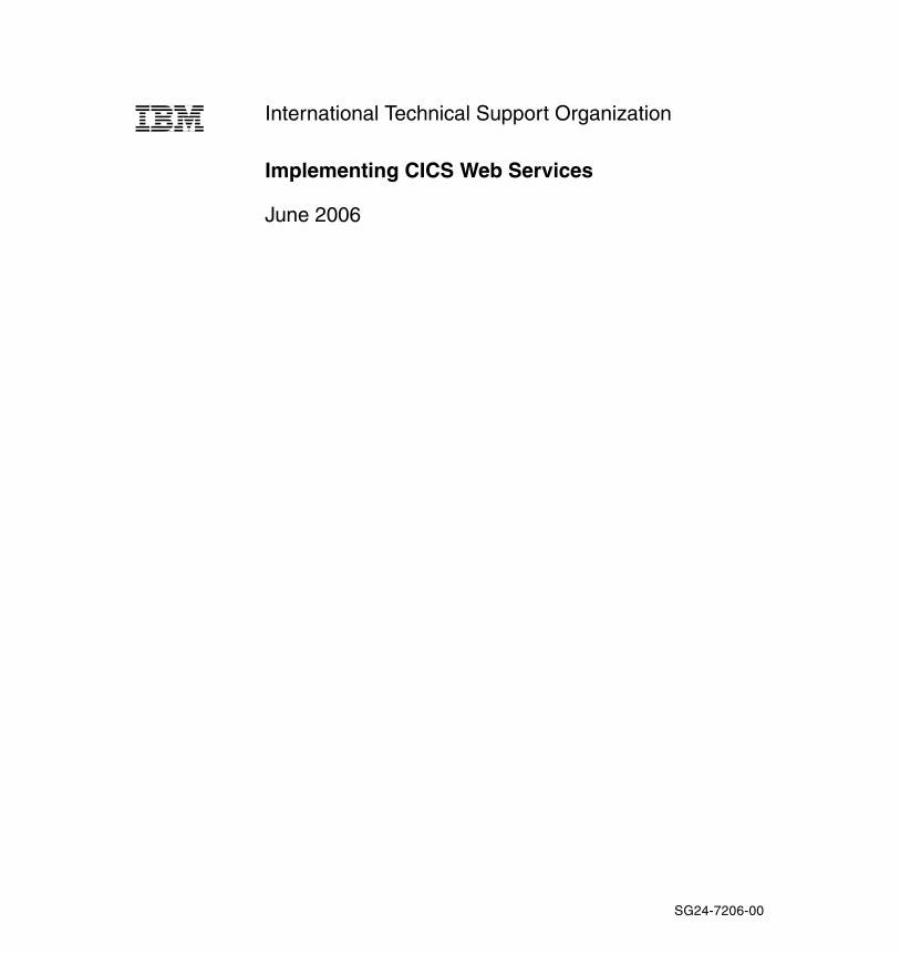
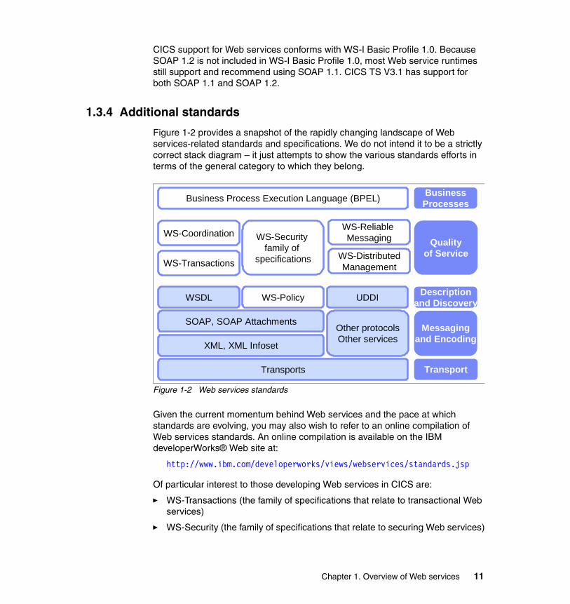
Figure 1-2 provides a snapshot of the rapidly changing landscape of Web services-related standards and specifications. We do not intend it to be a strictly correct stack diagram – it just attempts to show the various standards efforts in terms of the general category to which they belong.
Figure 1-2 Web services standards
Given the current momentum behind Web services and the pace at which standards are evolving, you may also wish to refer to an online compilation of Web services standards. An online compilation is available on the IBM developerWorks® Web site at:
http://www.ibm.com/developerworks/views/webservices/standards.jsp
Of particular interest to those developing Web services in CICS are:
� WS-Transactions (the family of specifications that relate to transactional Web services)
� WS-Security (the family of specifications that relate to securing Web services)
WS-Policy
WS-Security family of
specifications
UDDI
Qualityof Service
Messagingand Encoding
Transport
BusinessProcesses
Other protocolsOther services
Business Process Execution Language (BPEL)
Descriptionand DiscoveryWSDL
SOAP, SOAP Attachments
XML, XML Infoset
Transports
WS-Coordination
WS-Transactions
WS-Reliable Messaging
WS-DistributedManagement
Chapter 1. Overview of Web services 11
1.4 SOAP
In this section we focus mainly on SOAP 1.1.
1.4.1 The envelope
A SOAP message is an envelope containing zero or more headers and exactly one body:
� The envelope is the root element of the XML document, providing a container for control information, the addressee of a message, and the message itself.
� Headers contain control information, such as quality of service attributes.
� The body contains the message identification and its parameters.
� Both the headers and the body are child elements of the envelope element.
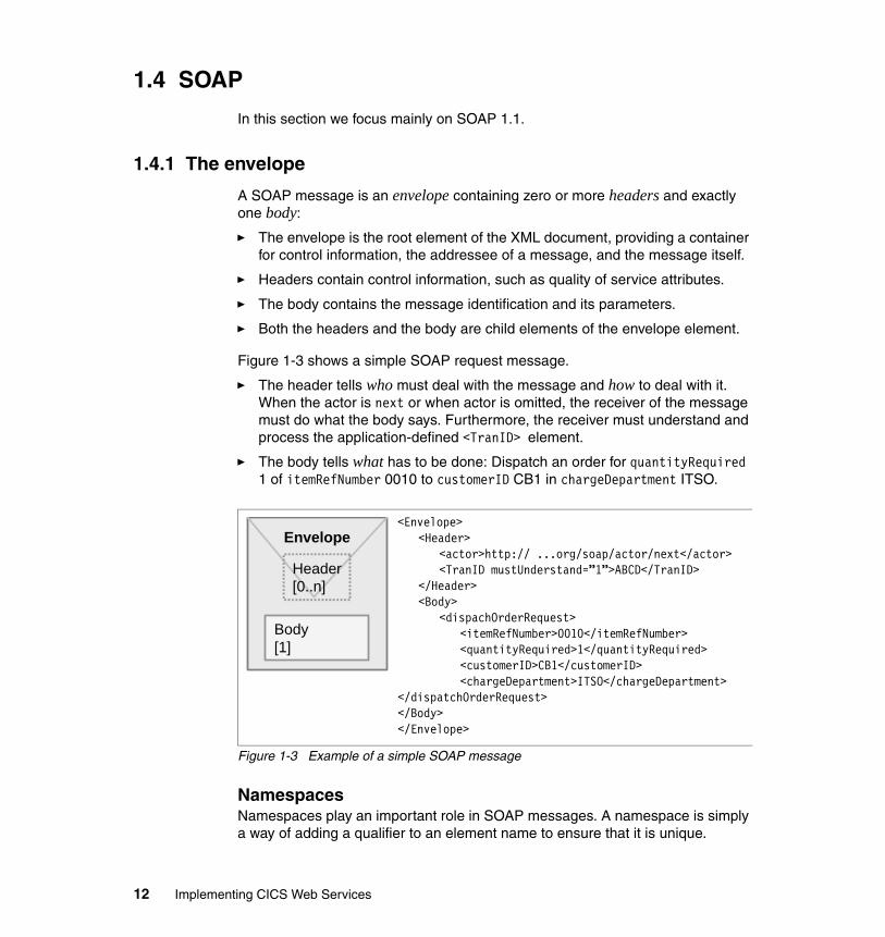
Figure 1-3 shows a simple SOAP request message.
� The header tells who must deal with the message and how to deal with it. When the actor is next or when actor is omitted, the receiver of the message must do what the body says. Furthermore, the receiver must understand and process the application-defined <TranID> element.
� The body tells what has to be done: Dispatch an order for quantityRequired 1 of itemRefNumber 0010 to customerID CB1 in chargeDepartment ITSO.
Figure 1-3 Example of a simple SOAP message
NamespacesNamespaces play an important role in SOAP messages. A namespace is simply a way of adding a qualifier to an element name to ensure that it is unique.
<Envelope><Header>
<actor>http:// ...org/soap/actor/next</actor><TranID mustUnderstand=”1”>ABCD</TranID>
</Header><Body>
<dispachOrderRequest><itemRefNumber>0010</itemRefNumber><quantityRequired>1</quantityRequired><customerID>CB1</customerID><chargeDepartment>ITSO</chargeDepartment>
</dispatchOrderRequest></Body></Envelope>
Envelope
Header[0..n]
Body[1]
12 Implementing CICS Web Services
For example we may have a message that contains an element <customer>. Customers are fairly common so it is very likely that many Web services will have customer elements. To ensure we know what customer we are talking about we declare a namespace for it, for example as follows:
xmlns:itso=”http://itso.ibm.com/CICS/catalogApplication
This identifies the prefix itso with the declared namespace. Then whenever we reference the element <customer> we prefix it with the namespace as follows: <itso:customer>. This identifies it uniquely as a customer type for our application. Namespaces can be defined as any unique string. They are often defined as URLs since URLs are generally globally unique, and they have to be in URL format. These URLs do not have to physically exist though.
The WS-I Basic Profile 1.0 requires that all application-specific elements in the body must be namespace qualified to avoid collisions between names.
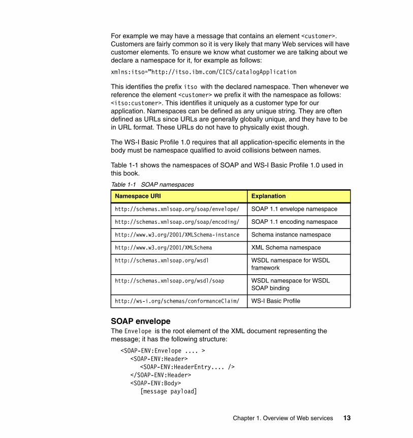
Table 1-1 shows the namespaces of SOAP and WS-I Basic Profile 1.0 used in this book.
Table 1-1 SOAP namespaces
SOAP envelopeThe Envelope is the root element of the XML document representing the message; it has the following structure:
<SOAP-ENV:Envelope .... ><SOAP-ENV:Header>
<SOAP-ENV:HeaderEntry.... /></SOAP-ENV:Header><SOAP-ENV:Body>
[message payload]
Namespace URI Explanation
http://schemas.xmlsoap.org/soap/envelope/ SOAP 1.1 envelope namespace
http://schemas.xmlsoap.org/soap/encoding/ SOAP 1.1 encoding namespace
http://www.w3.org/2001/XMLSchema-instance Schema instance namespace
http://www.w3.org/2001/XMLSchema XML Schema namespace
http://schemas.xmlsoap.org/wsdl WSDL namespace for WSDL framework
http://schemas.xmlsoap.org/wsdl/soap WSDL namespace for WSDL SOAP binding
http://ws-i.org/schemas/conformanceClaim/ WS-I Basic Profile
Chapter 1. Overview of Web services 13
</SOAP-ENV:Body></SOAP-ENV:Envelope>
In general, a SOAP message is a (possibly empty) set of headers plus one body. The SOAP envelope also defines the namespace for structuring messages. The entire SOAP message (headers and body) is wrapped in this envelope.
HeadersHeaders are a generic and flexible mechanism for extending a SOAP message in a decentralized and modular way without prior agreement between the parties involved. They allow control information to pass to the receiving SOAP server and also provide extensibility for message structures.
Headers are optional elements in the envelope. If present, the Header element must be the first immediate child element of a SOAP Envelope element. All immediate child elements of the Header element are called header entries.
There is a predefined header attribute called SOAP-ENV:mustUnderstand. The value of the mustUnderstand attribute is either 1 or 0. The absence of the SOAP mustUnderstand attribute is semantically equivalent to the value 0.
If the mustUnderstand attribute is present in a header entry and set to 1, the service provider must implement the semantics defined by the element:
<Header><thens:TranID mustUnderstand=”1”>ABCD</thens:TranID>
</Header>
In the example, the header entry specifies that a service invocation must fail if the service provider does not support the ability to process the TranID header.
A SOAP intermediary is an application that is capable of both receiving and forwarding SOAP messages on their way to the final destination. In realistic situations, not all parts of a SOAP message may be intended for the ultimate destination of the SOAP message, but, instead, may be intended for one or more of the intermediaries on the message path. Therefore, a second predefined header attribute, SOAP-ENV:actor, is used to identify the recipient of the header information. In SOAP 1.2 the actor attribute is renamed SOAP-ENV:role. The value of the SOAP actor attribute is the URI of the mediator, which is also the final destination of the particular header element (the mediator does not forward the header).
If the actor is omitted or set to the predefined default value, the header is for the actual recipient and the actual recipient is also the final destination of the message (body). The predefine value is:
http://schemas.xmlsoap.org/soap/actor/next
14 Implementing CICS Web Services
If a node on the message path does not recognize a mustUnderstand header and the node plays the role specified by the actor attribute, the node must generate a SOAP MustUnderstand fault. Whether the fault is sent back to the sender depends on the message exchange pattern in use. For request/response, the WS-I BP 1.0 requires the fault to be sent back to the sender. Also, according to WS-I BP 1.0, the receiver node must discontinue normal processing of the SOAP message after generating the fault message.
Headers can carry authentication data, digital signatures, encryption information, and transactional settings. They can also carry client-specific or project-specific controls and extensions to the protocol; the definition of headers is not just up to standards bodies.
BodyThe SOAP Body element provides a mechanism for exchanging information intended for the ultimate recipient of the message. The Body element is encoded as an immediate child element of the SOAP Envelope element. If a Header element is present, then the Body element must immediately follow the Header element. Otherwise it must be the first immediate child element of the Envelope element.
All immediate child elements of the Body element are called body entries, and each body entry is encoded as an independent element within the SOAP Body element. In the most simple case, the body of a basic SOAP message consists of an XML message as defined by the schema in the types section of the WSDL document. It is legal to have any valid XML as the body of the SOAP message, but WS-I conformance requires that the elements be namespace qualified.
Note: The header must not include service instructions (that would be used by the service implementation).
Chapter 1. Overview of Web services 15
Error handlingOne area where there are significant differences between the SOAP 1.1 and 1.2 specifications is in the handling of errors. Here we focus on the SOAP 1.1 specification for error handling.
SOAP itself predefines one body element, which is the fault element used for reporting errors. If present, the fault element must appear as a body entry and must not appear more than once. The children of the fault element are defined as follows:
� faultcode is a code that indicates the type of the fault. SOAP defines a small set of SOAP fault codes covering basic SOAP faults:
– soapenv:Client, indicating that the client sent an incorrectly formatted message
– soapenv:Server, for delivery problems
– soapenv:VersionMismatch, which can report any invalid namespaces specified on the Envelope element
– soapenv:MustUnderstand, for errors regarding the processing of header content
� faultstring is a human-readable description of the fault. It must be present in a fault element.
� faultactor is an optional field that indicates the URI of the source of the fault. The value of the faultactor attribute is a URI identifying the source that caused the error. Applications that do not act as the ultimate destination of the SOAP message must include the faultactor element in a SOAP fault element.
� detail is an application-specific field that contains detailed information about the fault. It must not be used to carry information about errors belonging to header entries. Therefore, the absence of the detail element in the fault element indicates that the fault is not related to the processing of the body element (the actual message).
For example, a soapenv:Server fault message is returned if the service implementation throws a SOAP Exception. The exception text is transmitted in the faultstring field.
Although SOAP 1.1 permits the use of custom-defined faultcodes, the WS-I Basic Profile only permits the use of the four codes defined in SOAP 1.1.
16 Implementing CICS Web Services
1.4.2 Communication styles
SOAP supports two different communication styles:
Document Also known as message-oriented style: This is a very flexible communication style that provides the best interoperability. The message body is any legal XML as defined in the types section of the WSDL document.
RPC The remote procedure call is a synchronous invocation of an operation which returns a result; it is conceptually similar to other RPCs.
1.4.3 Encodings
In distributed computing environments, encodings define how data values defined in the application can be translated to and from a protocol format. We refer to these translation steps as serialization and deserialization, or, synonymously, marshalling and unmarshalling.
When implementing a Web service, we have to choose one of the tools and programming or scripting languages that support the Web services model. However, the protocol format for Web services is XML, which is independent of the programming language. Thus, SOAP encodings tell the SOAP runtime environment how to translate from data structures constructed in a specific programming language into SOAP XML and vice versa.
The following encodings are defined:
SOAP encoding The SOAP encoding enables marshalling/unmarshalling of values of data types from the SOAP data model. This encoding is defined in the SOAP 1.1 standard.
Literal The literal encoding is a simple XML message that does not carry encoding information. Usually, an XML Schema describes the format and data types of the XML message.
1.4.4 Messaging modes
The two styles (RPC and document) and the two common encodings (SOAP encoding and literal) can be freely intermixed to produce what is called a SOAP messaging mode. Although SOAP supports four modes, only three of the four
Chapter 1. Overview of Web services 17
modes are generally used, and further, only two are preferred by the WS-I Basic Profile.
� Document/literal—Provides the best interoperability between language environments. The WS-I Basic Profile states that all Web service interactions should use the Document/literal mode.
� RPC/literal—Possible choice between certain implementations. Although RPC/literal is WS-I compliant, it is not frequently used in practice. There are a number of usability issues associated with RPC/literal.
� RPC/encoded—Early Java implementations supported this combination, but it does not provide interoperability with other implementations and is not recommended
� Document/encoded—Not used in practice.
You can find the SOAP 1.1 specification at the following URL:
http://www.w3.org/TR/2000/NOTE-SOAP-20000508
The SOAP 1.2 specification is at the following URL:
http://www.w3.org/TR/SOAP12
1.5 WSDL
This section introduces Web Services Description Language (WSDL) 1.1. WSDL uses XML to specify the characteristics of a Web service: what the Web service can do, where it resides, and how it is invoked. WSDL can be extended to allow descriptions of different bindings, regardless of what message formats or network protocols are used to communicate.
WSDL enables a service provider to specify the following characteristics of a Web service:
� Name of the Web service and addressing information
� Protocol and encoding style to be used when accessing the public operations of the Web service
� Type information: Operations, parameters, and data types comprising the interface of the Web service, plus a name for this interface
18 Implementing CICS Web Services
1.5.1 WSDL Document
A WSDL document contains the following main elements:
Types A container for data type definitions using some type system, usually XML Schema.
Message An abstract, typed definition of the data being communicated. A message can have one or more typed parts.
Port type An abstract set of one or more operations supported by one or more ports.
Operation An abstract description of an action supported by the service that defines the input and output message and optional fault message.
Binding A concrete protocol and data format specification for a particular port type. The binding information contains the protocol name, the invocation style, a service ID, and the encoding for each operation.
Port A single endpoint, which is defined as an aggregation of a binding and a network address.
Service A collection of related ports.
Note that WSDL does not introduce a new type definition language. WSDL recognizes the need for rich type systems for describing message formats and supports the XML Schema Definition (XSD) specification.
WSDL 1.1 introduces specific binding extensions for various protocols and message formats. There is a WSDL SOAP binding, which is capable of describing SOAP over HTTP. It is worth noting that WSDL does not define any mappings to a programming language; rather, the bindings deal with transport protocols. This is a major difference from interface description languages, such as the CORBA Interface Definition Language (IDL), which has language bindings.
You can find the WSDL 1.1 specification at the following URL:
http://www.w3.org/TR/wsdl
1.5.2 WSDL document anatomy
Figure 1-4 on page 21 shows the elements comprising a WSDL document and the various relationships between them.
Chapter 1. Overview of Web services 19
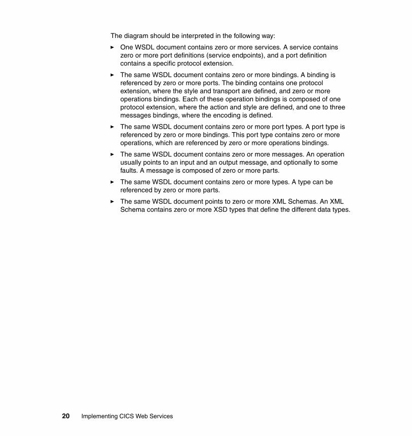
The diagram should be interpreted in the following way:
� One WSDL document contains zero or more services. A service contains zero or more port definitions (service endpoints), and a port definition contains a specific protocol extension.
� The same WSDL document contains zero or more bindings. A binding is referenced by zero or more ports. The binding contains one protocol extension, where the style and transport are defined, and zero or more operations bindings. Each of these operation bindings is composed of one protocol extension, where the action and style are defined, and one to three messages bindings, where the encoding is defined.
� The same WSDL document contains zero or more port types. A port type is referenced by zero or more bindings. This port type contains zero or more operations, which are referenced by zero or more operations bindings.
� The same WSDL document contains zero or more messages. An operation usually points to an input and an output message, and optionally to some faults. A message is composed of zero or more parts.
� The same WSDL document contains zero or more types. A type can be referenced by zero or more parts.
� The same WSDL document points to zero or more XML Schemas. An XML Schema contains zero or more XSD types that define the different data types.
20 Implementing CICS Web Services
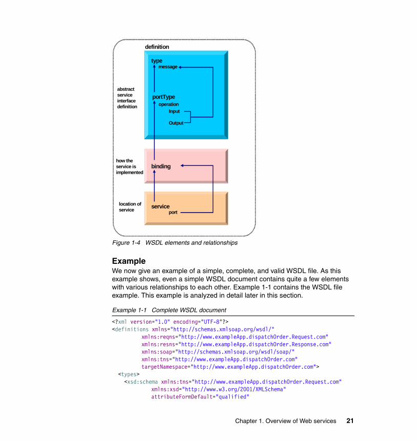
Figure 1-4 WSDL elements and relationships
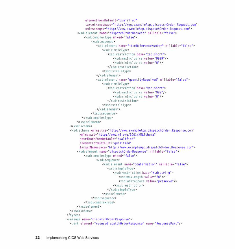
ExampleWe now give an example of a simple, complete, and valid WSDL file. As this example shows, even a simple WSDL document contains quite a few elements with various relationships to each other. Example 1-1 contains the WSDL file example. This example is analyzed in detail later in this section.
Example 1-1 Complete WSDL document
<?xml version="1.0" encoding="UTF-8"?><definitions xmlns="http://schemas.xmlsoap.org/wsdl/"
xmlns:reqns="http://www.exampleApp.dispatchOrder.Request.com" xmlns:resns="http://www.exampleApp.dispatchOrder.Response.com" xmlns:soap="http://schemas.xmlsoap.org/wsdl/soap/" xmlns:tns="http://www.exampleApp.dispatchOrder.com" targetNamespace="http://www.exampleApp.dispatchOrder.com">
<types> <xsd:schema xmlns:tns="http://www.exampleApp.dispatchOrder.Request.com"
xmlns:xsd="http://www.w3.org/2001/XMLSchema" attributeFormDefault="qualified"
type
binding
serviceport
Input
Output
portType
message
definition
operation
abstractserviceinterfacedefinition
how the service isimplemented
location ofservice
Chapter 1. Overview of Web services 21
elementFormDefault="qualified" targetNamespace="http://www.exampleApp.dispatchOrder.Request.com" xmlns:reqns="http://www.exampleApp.dispatchOrder.Request.com">
<xsd:element name="dispatchOrderRequest" nillable="false"> <xsd:complexType mixed="false"> <xsd:sequence> <xsd:element name="itemReferenceNumber" nillable="false"> <xsd:simpleType> <xsd:restriction base="xsd:short"> <xsd:maxInclusive value="9999"/> <xsd:minInclusive value="0"/> </xsd:restriction> </xsd:simpleType> </xsd:element> <xsd:element name="quantityRequired" nillable="false"> <xsd:simpleType> <xsd:restriction base="xsd:short"> <xsd:maxInclusive value="999"/> <xsd:minInclusive value="0"/> </xsd:restriction> </xsd:simpleType> </xsd:element>
</xsd:sequence> </xsd:complexType> </xsd:element> </xsd:schema> <xsd:schema xmlns:tns="http://www.exampleApp.dispatchOrder.Response.com"
xmlns:xsd="http://www.w3.org/2001/XMLSchema" attributeFormDefault="qualified" elementFormDefault="qualified" targetNamespace="http://www.exampleApp.dispatchOrder.Response.com">
<xsd:element name="dispatchOrderResponse" nillable="false"> <xsd:complexType mixed="false"> <xsd:sequence> <xsd:element name="confirmation" nillable="false"> <xsd:simpleType> <xsd:restriction base="xsd:string"> <xsd:maxLength value="20"/> <xsd:whiteSpace value="preserve"/> </xsd:restriction> </xsd:simpleType> </xsd:element> </xsd:sequence> </xsd:complexType> </xsd:element> </xsd:schema> </types> <message name="dispatchOrderResponse"> <part element="resns:dispatchOrderResponse" name="ResponsePart"/>
22 Implementing CICS Web Services
</message> <message name="dispatchOrderRequest"> <part element="reqns:dispatchOrderRequest" name="RequestPart"/> </message> <portType name="dispatchOrderPort"> <operation name="dispatchOrder"> <input message="tns:dispatchOrderRequest" name="DFH0XODSRequest"/> <output message="tns:dispatchOrderResponse" name="DFH0XODSResponse"/> </operation> </portType> <binding name="dispatchOrderSoapBinding" type="tns:dispatchOrderPort"> <soap:binding style="document"
transport="http://schemas.xmlsoap.org/soap/http"/> <operation name="dispatchOrder"> <soap:operation soapAction="" style="document"/> <input name="DFH0XODSRequest"> <soap:body parts="RequestPart" use="literal"/> </input> <output name="DFH0XODSResponse"> <soap:body parts="ResponsePart" use="literal"/> </output> </operation> </binding> <service name="dispatchOrderService"> <port binding="tns:dispatchOrderSoapBinding" name="dispatchOrderPort"> <soap:address
location="http://myserver:54321/exampleApp/services/dispatchOrderPort"/> </port> </service></definitions>
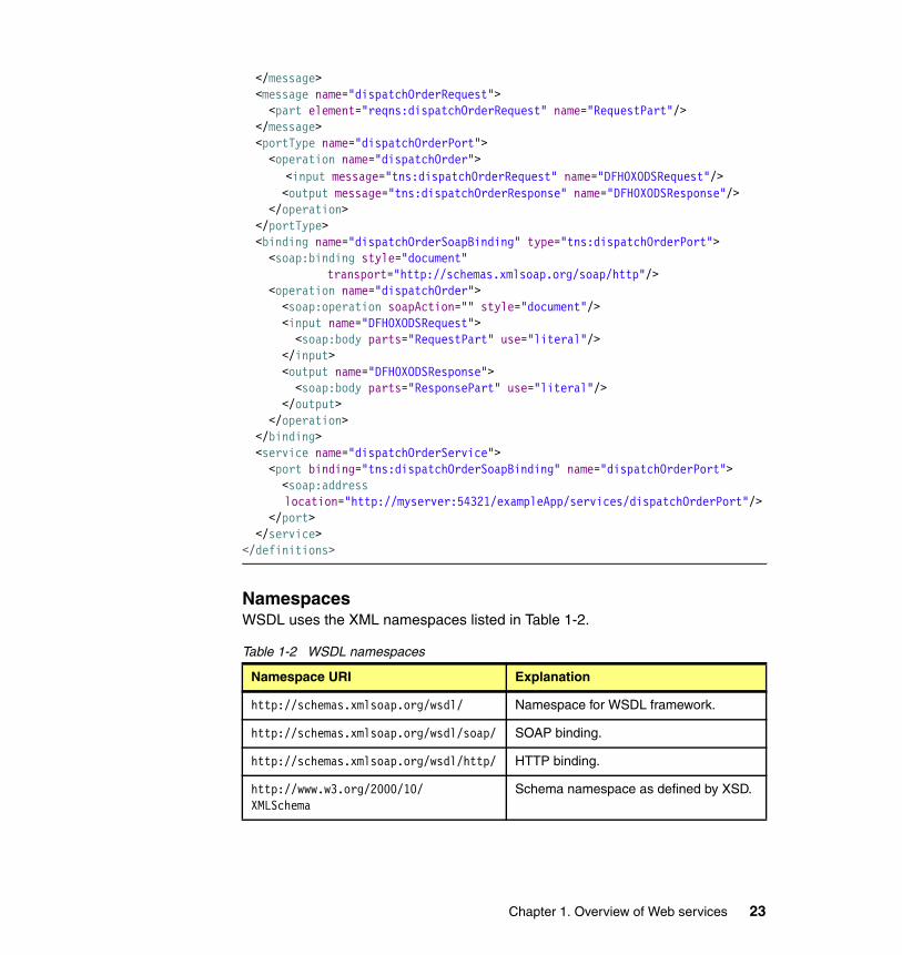
NamespacesWSDL uses the XML namespaces listed in Table 1-2.
Table 1-2 WSDL namespaces
Namespace URI Explanation
http://schemas.xmlsoap.org/wsdl/ Namespace for WSDL framework.
http://schemas.xmlsoap.org/wsdl/soap/ SOAP binding.
http://schemas.xmlsoap.org/wsdl/http/ HTTP binding.
http://www.w3.org/2000/10/XMLSchema
Schema namespace as defined by XSD.
Chapter 1. Overview of Web services 23
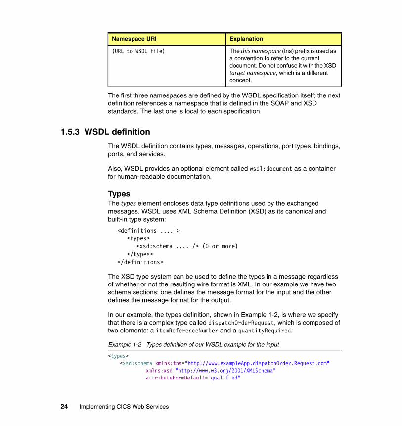
The first three namespaces are defined by the WSDL specification itself; the next definition references a namespace that is defined in the SOAP and XSD standards. The last one is local to each specification.
1.5.3 WSDL definition
The WSDL definition contains types, messages, operations, port types, bindings, ports, and services.
Also, WSDL provides an optional element called wsdl:document as a container for human-readable documentation.
TypesThe types element encloses data type definitions used by the exchanged messages. WSDL uses XML Schema Definition (XSD) as its canonical and built-in type system:
<definitions .... ><types>
<xsd:schema .... /> (0 or more)</types>
</definitions>
The XSD type system can be used to define the types in a message regardless of whether or not the resulting wire format is XML. In our example we have two schema sections; one defines the message format for the input and the other defines the message format for the output.
In our example, the types definition, shown in Example 1-2, is where we specify that there is a complex type called dispatchOrderRequest, which is composed of two elements: a itemReferenceNumber and a quantityRequired.
Example 1-2 Types definition of our WSDL example for the input
<types> <xsd:schema xmlns:tns="http://www.exampleApp.dispatchOrder.Request.com"
xmlns:xsd="http://www.w3.org/2001/XMLSchema" attributeFormDefault="qualified"
(URL to WSDL file) The this namespace (tns) prefix is used as a convention to refer to the current document. Do not confuse it with the XSD target namespace, which is a different concept.
Namespace URI Explanation
24 Implementing CICS Web Services
elementFormDefault="qualified" targetNamespace="http://www.exampleApp.dispatchOrder.Request.com" xmlns:reqns="http://www.exampleApp.dispatchOrder.Request.com">
<xsd:element name="dispatchOrderRequest" nillable="false"> <xsd:complexType mixed="false"> <xsd:sequence> <xsd:element name="itemReferenceNumber" nillable="false"> <xsd:simpleType> <xsd:restriction base="xsd:short"> <xsd:maxInclusive value="9999"/> <xsd:minInclusive value="0"/> </xsd:restriction> </xsd:simpleType> </xsd:element> <xsd:element name="quantityRequired" nillable="false"> <xsd:simpleType> <xsd:restriction base="xsd:short"> <xsd:maxInclusive value="999"/> <xsd:minInclusive value="0"/> </xsd:restriction> </xsd:simpleType> </xsd:element>
</xsd:sequence> </xsd:complexType> </xsd:element> </xsd:schema>..</types>
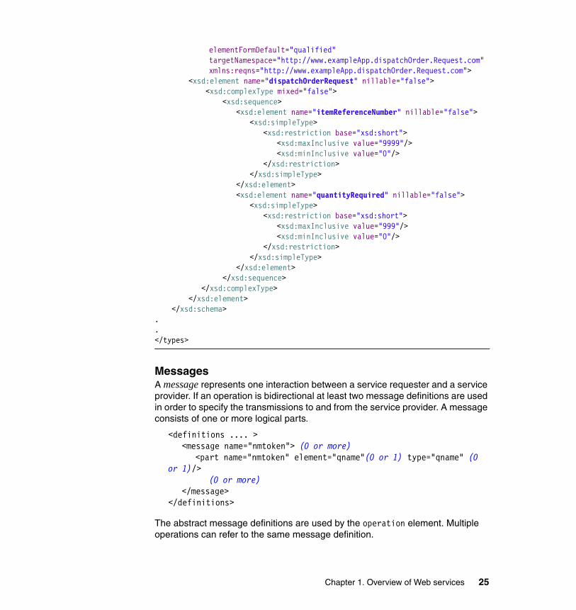
MessagesA message represents one interaction between a service requester and a service provider. If an operation is bidirectional at least two message definitions are used in order to specify the transmissions to and from the service provider. A message consists of one or more logical parts.
<definitions .... ><message name="nmtoken"> (0 or more)
<part name="nmtoken" element="qname"(0 or 1) type="qname" (0 or 1)/>
(0 or more)</message>
</definitions>
The abstract message definitions are used by the operation element. Multiple operations can refer to the same message definition.
Chapter 1. Overview of Web services 25
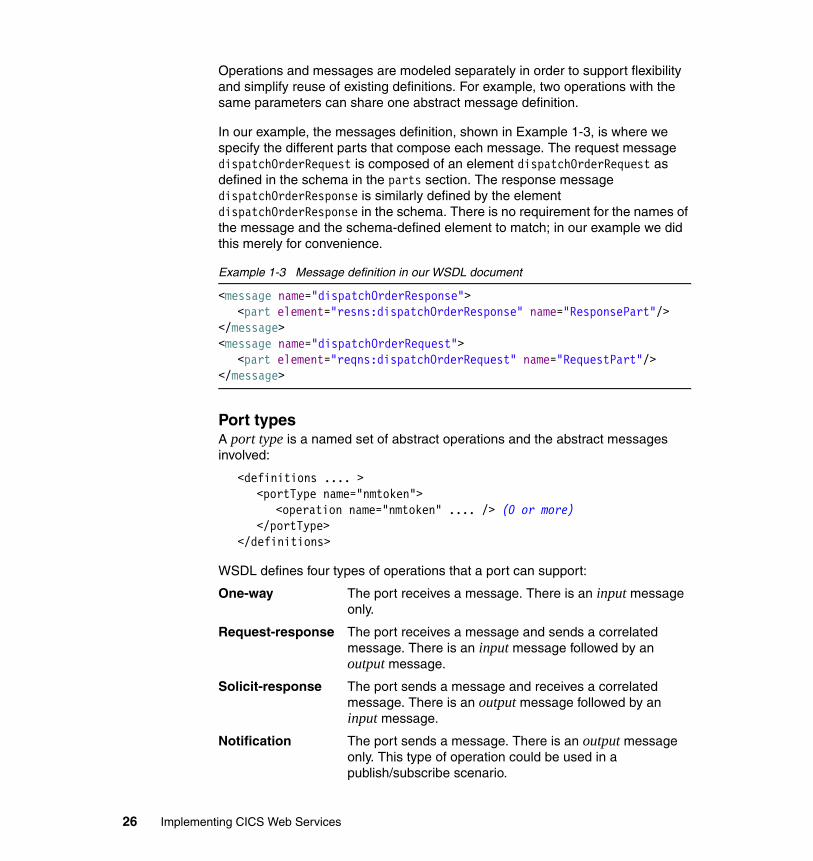
Operations and messages are modeled separately in order to support flexibility and simplify reuse of existing definitions. For example, two operations with the same parameters can share one abstract message definition.
In our example, the messages definition, shown in Example 1-3, is where we specify the different parts that compose each message. The request message dispatchOrderRequest is composed of an element dispatchOrderRequest as defined in the schema in the parts section. The response message dispatchOrderResponse is similarly defined by the element dispatchOrderResponse in the schema. There is no requirement for the names of the message and the schema-defined element to match; in our example we did this merely for convenience.
Example 1-3 Message definition in our WSDL document
<message name="dispatchOrderResponse"><part element="resns:dispatchOrderResponse" name="ResponsePart"/>
</message><message name="dispatchOrderRequest">
<part element="reqns:dispatchOrderRequest" name="RequestPart"/></message>
Port typesA port type is a named set of abstract operations and the abstract messages involved:
<definitions .... ><portType name="nmtoken">
<operation name="nmtoken" .... /> (0 or more)</portType>
</definitions>
WSDL defines four types of operations that a port can support:
One-way The port receives a message. There is an input message only.
Request-response The port receives a message and sends a correlated message. There is an input message followed by an output message.
Solicit-response The port sends a message and receives a correlated message. There is an output message followed by an input message.
Notification The port sends a message. There is an output message only. This type of operation could be used in a publish/subscribe scenario.
26 Implementing CICS Web Services
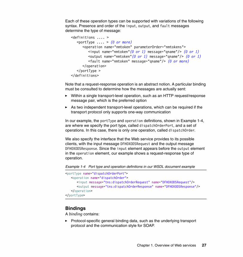
Each of these operation types can be supported with variations of the following syntax. Presence and order of the input, output, and fault messages determine the type of message:
<definitions .... ><portType .... > (0 or more)
<operation name="nmtoken" parameterOrder="nmtokens"><input name="nmtoken"(0 or 1) message="qname"/> (0 or 1)<output name="nmtoken"(0 or 1) message="qname"/> (0 or 1)<fault name="nmtoken" message="qname"/> (0 or more)
</operation></portType >
</definitions>
Note that a request-response operation is an abstract notion. A particular binding must be consulted to determine how the messages are actually sent:
� Within a single transport-level operation, such as an HTTP request/response message pair, which is the preferred option
� As two independent transport-level operations, which can be required if the transport protocol only supports one-way communication
In our example, the portType and operation definitions, shown in Example 1-4, are where we specify the port type, called dispatchOrderPort, and a set of operations. In this case, there is only one operation, called dispatchOrder.
We also specify the interface that the Web service provides to its possible clients, with the input message DFH0XODSRequest and the output message DFH0XODSResponse. Since the input element appears before the output element in the operation element, our example shows a request-response type of operation.
Example 1-4 Port type and operation definitions in our WSDL document example
<portType name="dispatchOrderPort"><operation name="dispatchOrder">
<input message="tns:dispatchOrderRequest" name="DFH0XODSRequest"/><output message="tns:dispatchOrderResponse" name="DFH0XODSResponse"/>
</operation></portType>
BindingsA binding contains:
� Protocol-specific general binding data, such as the underlying transport protocol and the communication style for SOAP.
Chapter 1. Overview of Web services 27
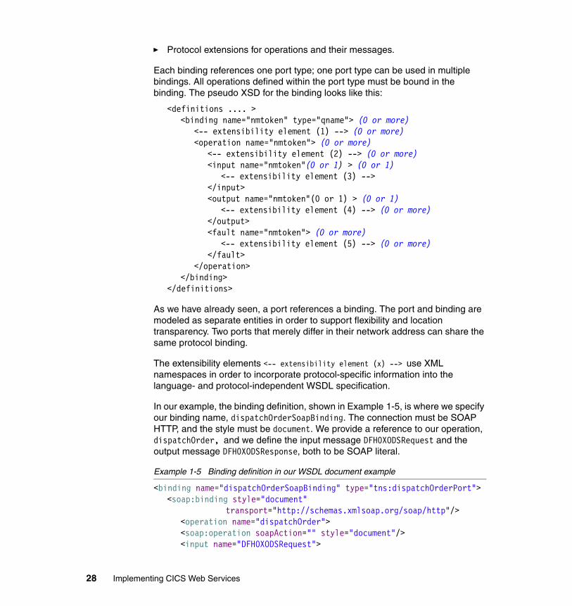
� Protocol extensions for operations and their messages.
Each binding references one port type; one port type can be used in multiple bindings. All operations defined within the port type must be bound in the binding. The pseudo XSD for the binding looks like this:
<definitions .... ><binding name="nmtoken" type="qname"> (0 or more)
<-- extensibility element (1) --> (0 or more)<operation name="nmtoken"> (0 or more)
<-- extensibility element (2) --> (0 or more)<input name="nmtoken"(0 or 1) > (0 or 1)
<-- extensibility element (3) --> </input><output name="nmtoken"(0 or 1) > (0 or 1)
<-- extensibility element (4) --> (0 or more)</output><fault name="nmtoken"> (0 or more)
<-- extensibility element (5) --> (0 or more)</fault>
</operation></binding>
</definitions>
As we have already seen, a port references a binding. The port and binding are modeled as separate entities in order to support flexibility and location transparency. Two ports that merely differ in their network address can share the same protocol binding.
The extensibility elements <-- extensibility element (x) --> use XML namespaces in order to incorporate protocol-specific information into the language- and protocol-independent WSDL specification.
In our example, the binding definition, shown in Example 1-5, is where we specify our binding name, dispatchOrderSoapBinding. The connection must be SOAP HTTP, and the style must be document. We provide a reference to our operation, dispatchOrder, and we define the input message DFH0XODSRequest and the output message DFH0XODSResponse, both to be SOAP literal.
Example 1-5 Binding definition in our WSDL document example
<binding name="dispatchOrderSoapBinding" type="tns:dispatchOrderPort"><soap:binding style="document"
transport="http://schemas.xmlsoap.org/soap/http"/><operation name="dispatchOrder"><soap:operation soapAction="" style="document"/><input name="DFH0XODSRequest">
28 Implementing CICS Web Services
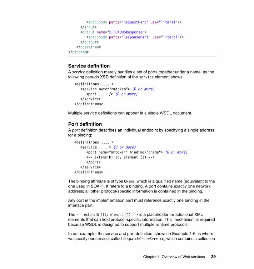
<soap:body parts="RequestPart" use="literal"/></input><output name="DFH0XODSResponse">
<soap:body parts="ResponsePart" use="literal"/></output>
</operation></binding>
Service definitionA service definition merely bundles a set of ports together under a name, as the following pseudo XSD definition of the service element shows.
<definitions .... ><service name="nmtoken"> (0 or more)
<port .... /> (0 or more)</service>
</definitions>
Multiple service definitions can appear in a single WSDL document.
Port definitionA port definition describes an individual endpoint by specifying a single address for a binding:
<definitions .... ><service .... > (0 or more)
<port name="nmtoken" binding="qname"> (0 or more)<-- extensibility element (1) --></port>
</service></definitions>
The binding attribute is of type QName, which is a qualified name (equivalent to the one used in SOAP). It refers to a binding. A port contains exactly one network address; all other protocol-specific information is contained in the binding.
Any port in the implementation part must reference exactly one binding in the interface part.
The <-- extensibility element (1) --> is a placeholder for additional XML elements that can hold protocol-specific information. This mechanism is required because WSDL is designed to support multiple runtime protocols.
In our example, the service and port definition, shown in Example 1-6, is where we specify our service, called dispatchOrderService, which contains a collection
Chapter 1. Overview of Web services 29
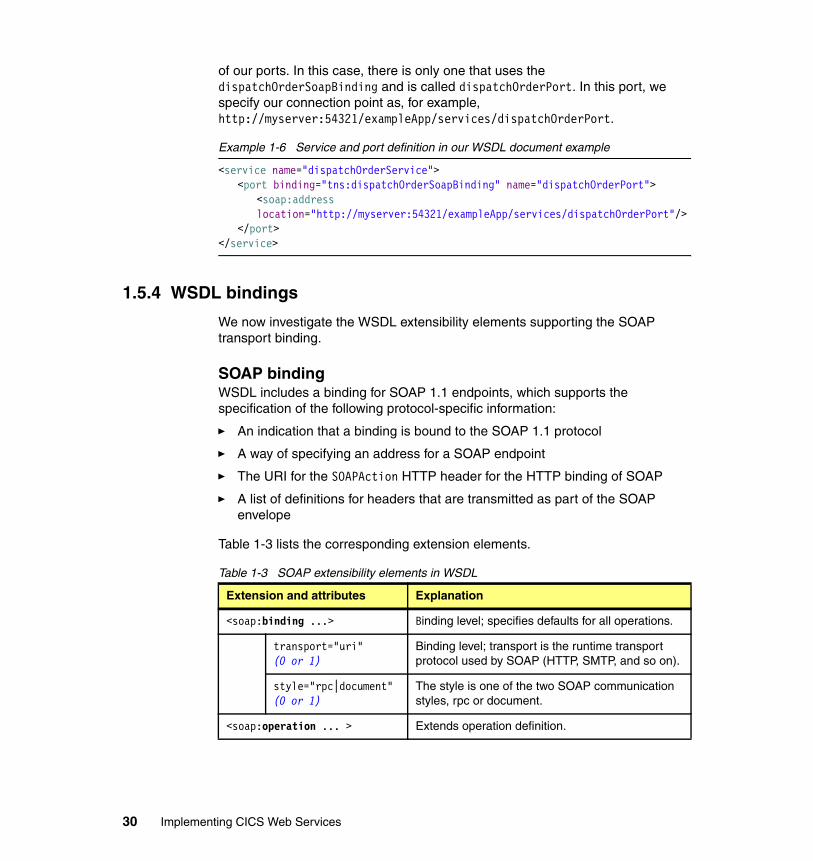
of our ports. In this case, there is only one that uses the dispatchOrderSoapBinding and is called dispatchOrderPort. In this port, we specify our connection point as, for example, http://myserver:54321/exampleApp/services/dispatchOrderPort.
Example 1-6 Service and port definition in our WSDL document example
<service name="dispatchOrderService"><port binding="tns:dispatchOrderSoapBinding" name="dispatchOrderPort">
<soap:addresslocation="http://myserver:54321/exampleApp/services/dispatchOrderPort"/>
</port></service>
1.5.4 WSDL bindings
We now investigate the WSDL extensibility elements supporting the SOAP transport binding.
SOAP bindingWSDL includes a binding for SOAP 1.1 endpoints, which supports the specification of the following protocol-specific information:
� An indication that a binding is bound to the SOAP 1.1 protocol
� A way of specifying an address for a SOAP endpoint
� The URI for the SOAPAction HTTP header for the HTTP binding of SOAP
� A list of definitions for headers that are transmitted as part of the SOAP envelope
Table 1-3 lists the corresponding extension elements.
Table 1-3 SOAP extensibility elements in WSDL
Extension and attributes Explanation
<soap:binding ...> Binding level; specifies defaults for all operations.
transport="uri" (0 or 1)
Binding level; transport is the runtime transport protocol used by SOAP (HTTP, SMTP, and so on).
style="rpc|document"(0 or 1)
The style is one of the two SOAP communication styles, rpc or document.
<soap:operation ... > Extends operation definition.
30 Implementing CICS Web Services
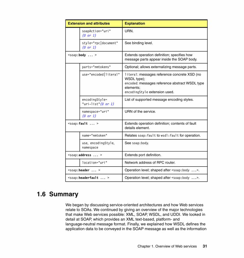
1.6 Summary
We began by discussing service-oriented architectures and how Web services relate to SOAs. We continued by giving an overview of the major technologies that make Web services possible: XML, SOAP, WSDL, and UDDI. We looked in detail at SOAP, which provides an XML text-based, platform- and language-neutral message format. Finally, we explained how WSDL defines the application data to be conveyed in the SOAP message as well as the information
soapAction="uri"(0 or 1)
URN.
style="rpc|document"(0 or 1)
See binding level.
<soap:body ... > Extends operation definition; specifies how message parts appear inside the SOAP body.
parts="nmtokens" Optional; allows externalizing message parts.
use="encoded|literal" literal: messages reference concrete XSD (no WSDL type);encoded: messages reference abstract WSDL type elements;encodingStyle extension used.
encodingStyle="uri-list"(0 or 1)
List of supported message encoding styles.
namespace="uri"(0 or 1)
URN of the service.
<soap:fault ... > Extends operation definition; contents of fault details element.
name="nmtoken" Relates soap:fault to wsdl:fault for operation.
use, encodingStyle, namespace
See soap:body.
<soap:address ... > Extends port definition.
location="uri" Network address of RPC router.
<soap:header ... > Operation level; shaped after <soap:body ...>.
<soap:headerfault ... > Operation level; shaped after <soap:body ...>.
Extension and attributes Explanation
Chapter 1. Overview of Web services 31
required to access the service, such as the transport protocol used and the location of the service.
32 Implementing CICS Web Services
Chapter 2. CICS support for Web services
In chapter 1 we introduced several Web services technologies. In this chapter we explain how to use Web services in CICS TS V3.1.
First, we provide an overview of the different Web services functions provided by CICS TS V3.1. We then look at how to prepare for running a CICS application as a service provider and at what processing occurs when a service request arrives in CICS. Similarly, we consider how to configure CICS as a service requester and how CICS processes an outbound request from a service requester application.
We also describe the new CICS resource definitions that are required to support Web services, URIMAP, PIPELINE, WEBSERVICE, and TCPIPSERVICE. And we explain how you can control the processing of a Web service request using message handler and SOAP header processing programs.
2
© Copyright IBM Corp. 2006. All rights reserved. 33
2.1 Overview
What the World Wide Web did for interactions between programs and end users, Web services can do for program-to-program interactions. CICS support for Web services makes it possible for CICS applications to be integrated more rapidly, easily, and cheaply than ever before.
Application programs running in CICS TS V3.1 can participate in a heterogeneous Web services environment as service requesters, service providers, or both, using either an HTTP transport or a WebSphere MQ transport.
CICS TS V3.1 provides the following new functions:
� It includes a new Web services assistant utility.
The Web services assistant utility contains two programs, DFHWS2LS and DFHLS2WS. DFHWS2LS helps you map an existing WSDL document into a high-level programming language data structure, while DFHLS2WS creates a new WSDL document from an existing language structure. The Web services assistant supports the following programming languages:
– COBOL – PL/I – C– C++
� It supports two different approaches to deploying your CICS applications in a Web services environment.
– You can use the Web services assistant.
The Web services assistant helps you deploy an application with the least amount of programming effort. For example, if you want to expose an existing application as a Web service, you can start with a high-level language data structure, and use DFHLS2WS to generate the Web services description. Alternatively, if you want to communicate with an existing Web service, you can start with its Web service description and use DFHWS2LS to generate a high-level language structure that you can use in your program.
Both DFHLS2WS and DFHWS2LS also generate a file called the wsbind file. When your application runs, CICS uses the wsbind file to transform your application data into a SOAP message on output and to transform the SOAP message to application data on input.
– You can take complete control of the processing of your data.
You can write your own code to map between your application data and the message that flows between the service requester and provider. For
34 Implementing CICS Web Services
example, if you want to use non-SOAP messages within the Web service infrastructure, you can write your own code to transform between the message format and the format used by your application.
� It reads a pipeline configuration file created by the CICS system programmer to determine which message handlers should be invoked in a pipeline.
A message handler is a program in which you can perform your own processing of Web service requests and responses. A pipeline is a set of message handlers that are executed in sequence.
A pipeline can be configured as a service requester pipeline or a service provider pipeline, but not both.
You can write your own message handlers to perform processing on request and response messages.
� It supplies message handlers designed especially to help you process SOAP messages.
CICS provides special SOAP message handler programs that can help you to configure your pipeline as a SOAP node.
– A service requester pipeline is the initial SOAP sender for the request, and the ultimate SOAP receiver for the response.
– A service provider pipeline is the ultimate SOAP receiver for the request, and the initial SOAP sender for the response.
The CICS-provided SOAP message handlers can be configured to invoke one or more user-written SOAP header processing programs and to enforce the presence of particular headers in the SOAP message.
� It allows you to configure many different pipelines.
You can configure a pipeline to support SOAP 1.1 or SOAP 1.2. Within your CICS system, you can have some pipelines that support SOAP 1.1 and others that support SOAP 1.2.
� It provides the following new resource definitions to help you configure support for Web services:
– PIPELINE
– URIMAP
– WEBSERVICE
Restriction: You cannot configure a CICS pipeline to function as an intermediary node in a SOAP message path.
Chapter 2. CICS support for Web services 35
� It provides the following new EXEC CICS application programming interface (API) commands:
– SOAPFAULT ADD | CREATE | DELETE
– INQUIRE WEBSERVICE
– INVOKE WEBSERVICE
� It conforms to open standards including:
– SOAP 1.1 and 1.2
– HTTP 1.1
– WSDL 1.1
� It ensures maximum interoperability with other Web services implementations by conforming with the Web Services Interoperability Organization (WS-I) Basic Profile 1.0.
� It supports the WS-Atomic Transaction specification.
Note: CICS TS V3.1 includes some specific enhancements that are related to Web services implementation using HTTP. In particular, Web Support in CICS TS V3.1 contains the following improvements:
� HTTP
– Concurrent session limit raised from 900 (in CICS TS V2.3) to 65000 per region.
– There is no affinity to long running CWXN transactions.
� HTTPS
– Concurrent session limit raised from 250 (in CICS TS V2.3) to 65000 per region.
– No affinity to SSL TCB for duration of connection.
– SSL TCB per connection now not required.
– No affinity to long running CWXN transaction.
– Easy choice over Cipher suites specified on TCPIPSERVICE definition.
– Sysplex-wide cache for SSL session ID.
Customers using the Web interface can now exploit persistent sessions for large networks, as opposed to having to make and break connections with every request. These customers will make CPU savings. Customers who had small networks and were already able to exploit persistent connections will see up to about 4% increase on average size applications. They will however benefit from a much greater number of concurrent sessions per region.
36 Implementing CICS Web Services
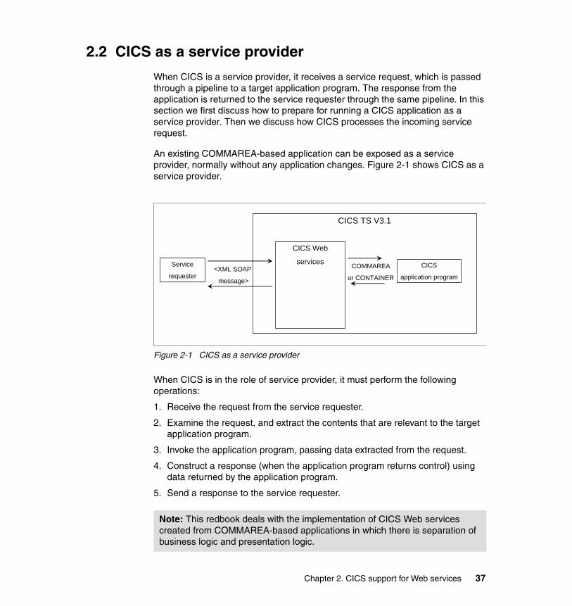
2.2 CICS as a service provider
When CICS is a service provider, it receives a service request, which is passed through a pipeline to a target application program. The response from the application is returned to the service requester through the same pipeline. In this section we first discuss how to prepare for running a CICS application as a service provider. Then we discuss how CICS processes the incoming service request.
An existing COMMAREA-based application can be exposed as a service provider, normally without any application changes. Figure 2-1 shows CICS as a service provider.
Figure 2-1 CICS as a service provider
When CICS is in the role of service provider, it must perform the following operations:
1. Receive the request from the service requester.
2. Examine the request, and extract the contents that are relevant to the target application program.
3. Invoke the application program, passing data extracted from the request.
4. Construct a response (when the application program returns control) using data returned by the application program.
5. Send a response to the service requester.
Note: This redbook deals with the implementation of CICS Web services created from COMMAREA-based applications in which there is separation of business logic and presentation logic.
CICS TS V3.1
Service
requesterCICS
application program
CICS Web
services<XML SOAP
message>
COMMAREA
or CONTAINER
Chapter 2. CICS support for Web services 37
2.2.1 Preparing to run a CICS application as a service provider
Suppose that you have an existing CICS application that you wish to expose as a Web service which uses the HTTP transport. Suppose also that you wish to use the Web services assistant rather than taking control of the processing yourselves. You would perform the following steps:
1. Generate the wsbind and WSDL files.
a. Create an HFS directory in which to store the generated files. For example, you might create a directory named /u/SharedProjectDirectory/MyFirstWebServiceProvider.
b. Run the DFHLS2WS program. The input you provide to the program includes the following:
• The names of the partitioned data set members that contain the high-level language structures the application program uses to describe the Web service request and the Web service response
• The fully qualified HFS names of the wsbind file and the file into which the Web service description is to be written (the WSDL file)
• The relative URI that a client will use to access the Web service
• How CICS should pass data to the target application program (COMMAREA or container)
2. Create a TCPIPSERVICE resource definition.
The resource definition should specify PROTOCOL(HTTP) and supply information about the port on which inbound requests are received.
3. Create a PIPELINE resource definition.
a. Create a service provider pipeline configuration file.
A pipeline configuration file is an XML file that describes, among other things, the message handler programs and the SOAP header processing programs that CICS invokes when it processes the pipeline.
b. Create an HFS directory in which to store installable wsbind and WSDL files.
Note: Typically, an application developer would perform this step.
Note: Typically, a systems programmer would perform this step and the subsequent steps.
38 Implementing CICS Web Services
We call this directory the “pickup” directory since CICS will pick up the wsbind and WSDL files from this directory and store them on a “shelf” directory.
c. Create an HFS directory for CICS to store installed wsbind files in.
We call this directory the “shelf” directory.
d. Create a PIPELINE resource definition to handle the Web service request.
• Specify the CONFIGFILE attribute to point to the file created in step 3a.
• Specify the WSDIR attribute to point to the directory created in step 3b.
• Specify the SHELF attribute to point to the directory created in step 3c.
e. Copy the wsbind and WSDL files created in step 1 to the pickup directory created in step 3b.
4. Install the TCPIPSERVICE and PIPELINE resource definitions.
When the CICS system programmer installs the PIPELINE definition, CICS scans the pickup directory for wsbind files. When CICS finds the wsbind file created in step 1, CICS dynamically creates and installs a WEBSERVICE resource definition for it. CICS derives the name of the WEBSERVICE definition from the name of the wsbind file. The WEBSERVICE definition identifies the name of the associated PIPELINE definition and points to the location of the wsbind file in the HFS.
During the installation of the WEBSERVICE resource:
– CICS dynamically creates and installs a URIMAP resource definition. CICS bases the definition on the URI specified in the input to DFHLS2WS in step 1 and stored by DFHLS2WS in the wsbind file.
– CICS uses the wsbind file to create main storage control blocks to map the inbound service request (XML) to a COMMAREA or a container and to map to XML the outbound COMMAREA or container that contains the response data.
5. Publish the WSDL files to the service requester clients.
a. Customize the location attribute on the <address> element in the WSDL file so that its value specifies the TCP/IP server name of the machine hosting the service and the port number defined in the TCPIPSERVICE defined in step 2.
b. Publish the WSDL to any parties wishing to create clients to this Web service.
Chapter 2. CICS support for Web services 39
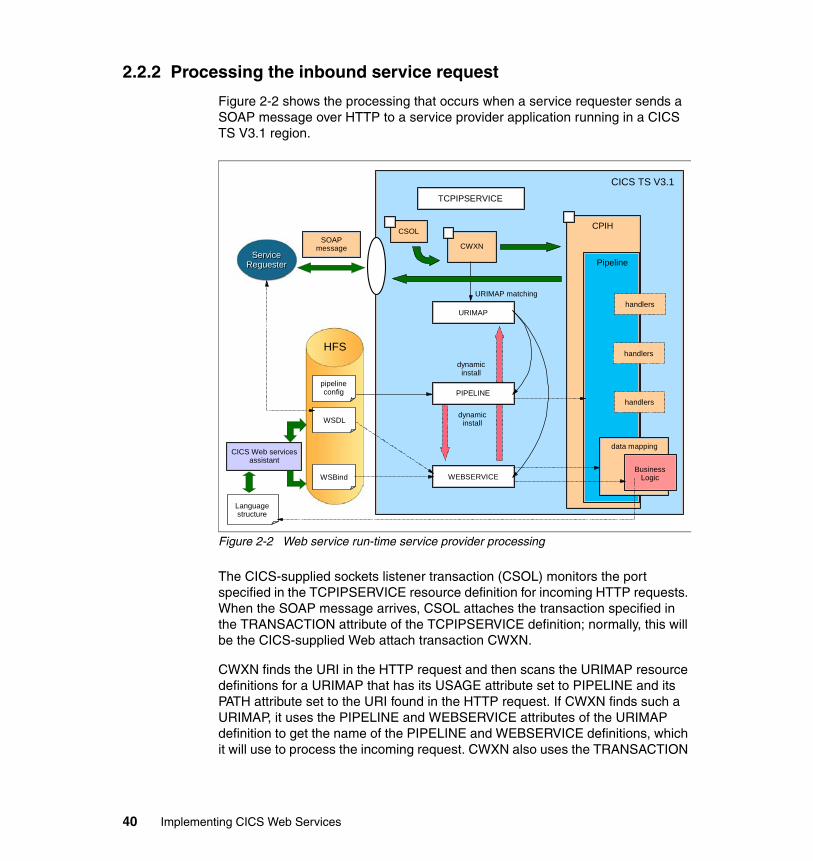
2.2.2 Processing the inbound service request
Figure 2-2 shows the processing that occurs when a service requester sends a SOAP message over HTTP to a service provider application running in a CICS TS V3.1 region.
Figure 2-2 Web service run-time service provider processing
The CICS-supplied sockets listener transaction (CSOL) monitors the port specified in the TCPIPSERVICE resource definition for incoming HTTP requests. When the SOAP message arrives, CSOL attaches the transaction specified in the TRANSACTION attribute of the TCPIPSERVICE definition; normally, this will be the CICS-supplied Web attach transaction CWXN.
CWXN finds the URI in the HTTP request and then scans the URIMAP resource definitions for a URIMAP that has its USAGE attribute set to PIPELINE and its PATH attribute set to the URI found in the HTTP request. If CWXN finds such a URIMAP, it uses the PIPELINE and WEBSERVICE attributes of the URIMAP definition to get the name of the PIPELINE and WEBSERVICE definitions, which it will use to process the incoming request. CWXN also uses the TRANSACTION
ServiceServiceReguesterReguester
pipelineconfig
WSBind
WSDL
HFS
SOAP message
CICS TS V3.1
CPIH
Pipeline
data mapping
BusinessLogic
handlers
TCPIPSERVICE
CSOL
CWXN
URIMAP
PIPELINE
WEBSERVICE
URIMAP matching
dynamicinstall
dynamicinstall
Languagestructure
CICS Web services assistant
handlers
handlers
40 Implementing CICS Web Services
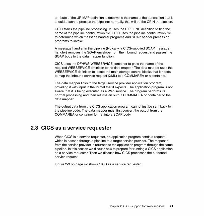
attribute of the URIMAP definition to determine the name of the transaction that it should attach to process the pipeline; normally, this will be the CPIH transaction.
CPIH starts the pipeline processing. It uses the PIPELINE definition to find the name of the pipeline configuration file. CPIH uses the pipeline configuration file to determine which message handler programs and SOAP header processing programs to invoke.
A message handler in the pipeline (typically, a CICS-supplied SOAP message handler) removes the SOAP envelope from the inbound request and passes the SOAP body to the data mapper function.
CICS uses the DFHWS-WEBSERVICE container to pass the name of the required WEBSERVICE definition to the data mapper. The data mapper uses the WEBSERVICE definition to locate the main storage control blocks that it needs to map the inbound service request (XML) to a COMMAREA or a container.
The data mapper links to the target service provider application program, providing it with input in the format that it expects. The application program is not aware that it is being executed as a Web service. The program performs its normal processing and then returns an output COMMAREA or container to the data mapper.
The output data from the CICS application program cannot just be sent back to the pipeline code. The data mapper must first convert the output from the COMMAREA or container format into a SOAP body.
2.3 CICS as a service requester
When CICS is a service requester, an application program sends a request, which is passed through a pipeline to a target service provider. The response from the service provider is returned to the application program through the same pipeline. In this section we discuss how to prepare for running a CICS application as a service requester. Then we discuss how CICS processes the outbound service request.
Figure 2-3 on page 42 shows CICS as a service requester.
Chapter 2. CICS support for Web services 41
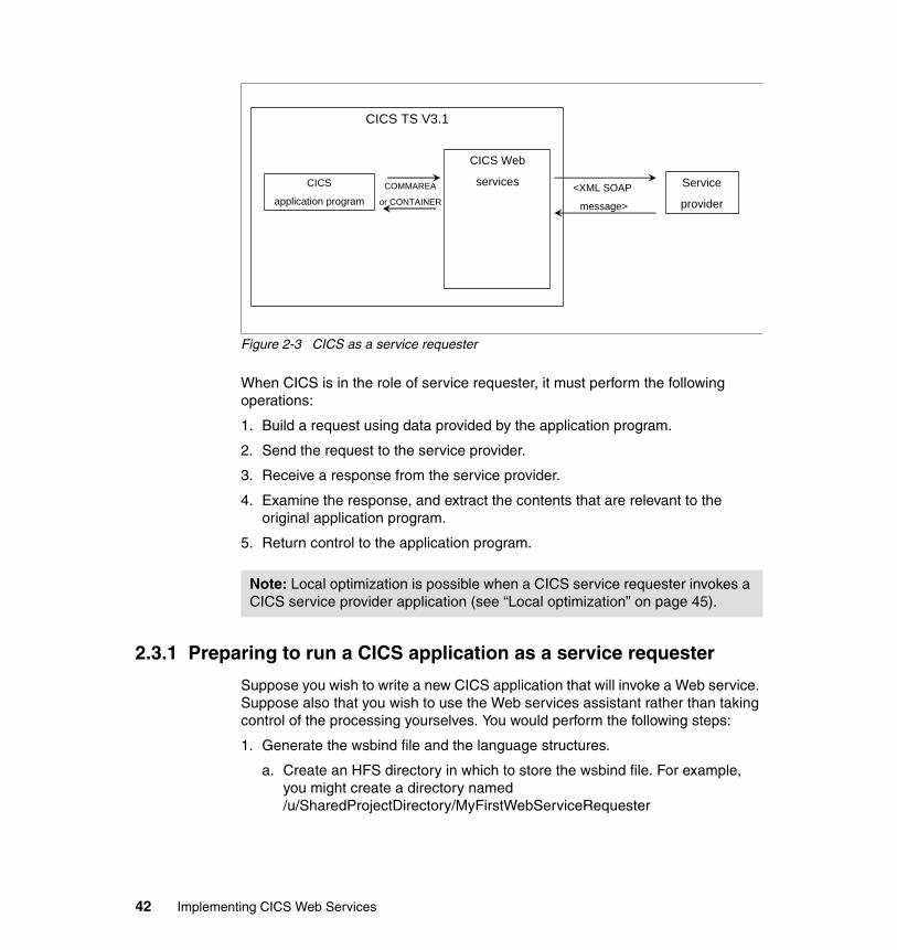
Figure 2-3 CICS as a service requester
When CICS is in the role of service requester, it must perform the following operations:
1. Build a request using data provided by the application program.
2. Send the request to the service provider.
3. Receive a response from the service provider.
4. Examine the response, and extract the contents that are relevant to the original application program.
5. Return control to the application program.
2.3.1 Preparing to run a CICS application as a service requester
Suppose you wish to write a new CICS application that will invoke a Web service. Suppose also that you wish to use the Web services assistant rather than taking control of the processing yourselves. You would perform the following steps:
1. Generate the wsbind file and the language structures.
a. Create an HFS directory in which to store the wsbind file. For example, you might create a directory named /u/SharedProjectDirectory/MyFirstWebServiceRequester
Note: Local optimization is possible when a CICS service requester invokes a CICS service provider application (see “Local optimization” on page 45).
Service
provider<XML SOAP
message>
CICS TS V3.1
CICS
application program
CICS Web
servicesCOMMAREA
or CONTAINER
42 Implementing CICS Web Services
b. Run the DFHWS2LS program. The input you provide to the program includes the following:
• The fully qualified HFS name of the WSDL file that describes the Web service you want to request.
• The names of the partitioned data set members into which DFHWS2LS should put the high-level language structures it generates. The application program uses the language structures to describe the Web service request and the Web service response.
2. Create a PIPELINE resource definition.
a. Create a service requester pipeline configuration file.
The pipeline configuration file describes the message handler programs and the SOAP header processing programs that CICS will invoke when it processes the pipeline.
b. Create an HFS directory in which to store installable wsbind files.
CICS will pick up the wsbind file from this directory and store it on a “shelf” directory.
c. Create the shelf directory for CICS to store installed wsbind files in.
d. Create a PIPELINE resource definition to handle the Web service request:
• Specify the CONFIGFILE attribute to point to the file created in step 2a.
• Specify the WSDIR attribute to point to the directory created in step 2b.
• Specify the SHELF attribute to point to the directory created in step 2c.
e. Copy the wsbind file created in step 1to the pickup directory created in step 2b.
3. Install the PIPELINE resource definition.
When the CICS system programmer installs the PIPELINE definition, CICS scans the pickup directory for wsbind files. When CICS finds the wsbind file created in step 1, CICS dynamically creates and installs a WEBSERVICE resource definition for it. CICS derives the name of the WEBSERVICE definition from the name of the wsbind file. The WEBSERVICE definition identifies the name of the associated PIPELINE definition and points to the location of the wsbind file in the HFS.
Note: Typically, an application developer would perform this step.
Note: Typically, a systems programmer would perform this step.
Chapter 2. CICS support for Web services 43
During the installation of the WEBSERVICE resource, CICS uses the wsbind file to create main storage control blocks to map the outbound service request to an XML document and to map the inbound XML response document to a language structure.
4. Use the language structure generated in step 1 to write the application program.
a. The application issues the following command to place the outbound data into container DFHWS-DATA:
EXEC CICS PUT CONTAINER(DFHWS-DATA) CHANNEL(name_of_channel) FROM(data_area)
b. It then issues the following command to invoke the Web service:
EXEC CICS INVOKE WEBSERVICE(name_of_WEBSERVICE_definition) CHANNEL(name_of_channel) OPERATION(name_of_operation)
2.3.2 Processing the outbound service request
Figure 2-4 shows the processing that occurs when a service requester running in a CICS TS V3.1 region sends a SOAP message to a service provider.
Note: Typically, a systems programmer would perform this step.
Note: Typically, an application developer would perform this step.
44 Implementing CICS Web Services
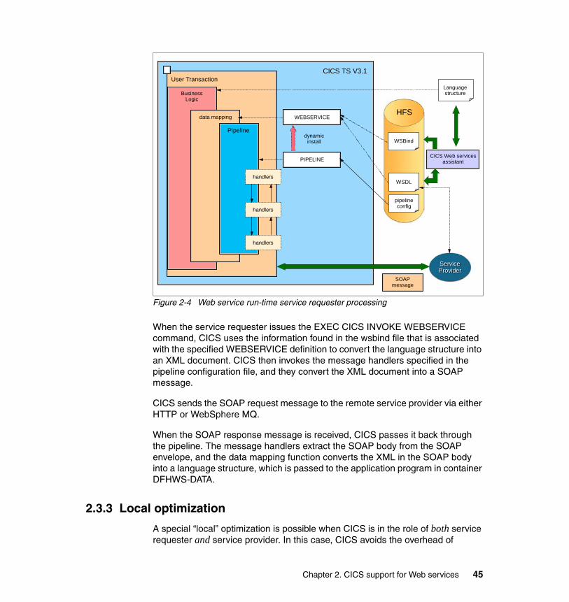
Figure 2-4 Web service run-time service requester processing
When the service requester issues the EXEC CICS INVOKE WEBSERVICE command, CICS uses the information found in the wsbind file that is associated with the specified WEBSERVICE definition to convert the language structure into an XML document. CICS then invokes the message handlers specified in the pipeline configuration file, and they convert the XML document into a SOAP message.
CICS sends the SOAP request message to the remote service provider via either HTTP or WebSphere MQ.
When the SOAP response message is received, CICS passes it back through the pipeline. The message handlers extract the SOAP body from the SOAP envelope, and the data mapping function converts the XML in the SOAP body into a language structure, which is passed to the application program in container DFHWS-DATA.
2.3.3 Local optimization
A special “local” optimization is possible when CICS is in the role of both service requester and service provider. In this case, CICS avoids the overhead of
ServiceServiceProviderProvider
WSBind
WSDL
HFS
SOAP message
CICS TS V3.1User Transaction
BusinessLogic
PIPELINE
WEBSERVICE
dynamicinstall
Languagestructure
CICS Web services assistant
data mapping
Pipeline
handlers
handlers
handlers
pipelineconfig
Chapter 2. CICS support for Web services 45
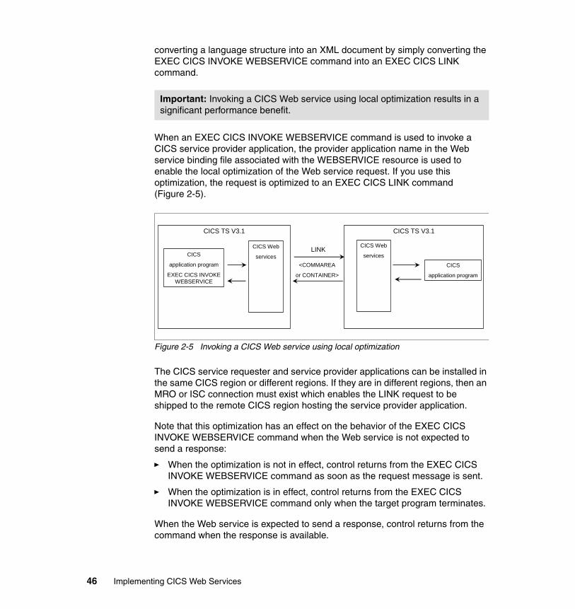
converting a language structure into an XML document by simply converting the EXEC CICS INVOKE WEBSERVICE command into an EXEC CICS LINK command.
When an EXEC CICS INVOKE WEBSERVICE command is used to invoke a CICS service provider application, the provider application name in the Web service binding file associated with the WEBSERVICE resource is used to enable the local optimization of the Web service request. If you use this optimization, the request is optimized to an EXEC CICS LINK command (Figure 2-5).
Figure 2-5 Invoking a CICS Web service using local optimization
The CICS service requester and service provider applications can be installed in the same CICS region or different regions. If they are in different regions, then an MRO or ISC connection must exist which enables the LINK request to be shipped to the remote CICS region hosting the service provider application.
Note that this optimization has an effect on the behavior of the EXEC CICS INVOKE WEBSERVICE command when the Web service is not expected to send a response:
� When the optimization is not in effect, control returns from the EXEC CICS INVOKE WEBSERVICE command as soon as the request message is sent.
� When the optimization is in effect, control returns from the EXEC CICS INVOKE WEBSERVICE command only when the target program terminates.
When the Web service is expected to send a response, control returns from the command when the response is available.
Important: Invoking a CICS Web service using local optimization results in a significant performance benefit.
CICS TS V3.1
CICS
application program
CICS Web
services<COMMAREA
or CONTAINER>
LINK
CICS TS V3.1
CICS Web
servicesCICS
application program
EXEC CICS INVOKEWEBSERVICE
46 Implementing CICS Web Services
2.4 CICS resources for Web services
We now look in more detail at what CICS resources a systems programmer must implement in order to enable Web services in a CICS environment. In Chapter 3, “Web services using HTTP” on page 73 we describe the resources that we created in order to enable Web services in our environment.
2.4.1 URIMAP
The URIMAP resource definition is used to define one of three different Web-related facilities in CICS. It is the value of the USAGE attribute on a URIMAP definition that determines which of the three facilities that particular definition controls.
1. Requests from a Web client, to CICS as an HTTP server
URIMAP definitions for requests for CICS as an HTTP server have a USAGE attribute of SERVER. These URIMAP definitions match the URLs of HTTP requests that CICS expects to receive from a Web client, and they define how CICS should provide a response to each request. You can use a URIMAP definition to tell CICS to:
– Provide a static response to the HTTP request, using a document template or z/OS UNIX® System Services HFS file
– Provide a dynamic response to the HTTP request, using an application program that issues EXEC CICS WEB application programming interface commands
– Redirect the request to another server, either temporarily or permanently
For CICS as an HTTP server, URIMAP definitions incorporate most of the functions that were previously provided by the analyzer program specified on the TCPIPSERVICE definition. An analyzer program may still be involved in the processing path if required.
2. Requests to a server, from CICS as an HTTP client
URIMAP definitions for requests from CICS as an HTTP client have a USAGE attribute of CLIENT. These URIMAP definitions specify URLs that are used when a user application, acting as a Web client, makes a request through CICS Web support to an HTTP server. Setting up a URIMAP definition for this
Restriction: You can use this optimization only if the service provider application and the service requester application are deployed with the Web services assistant.
Chapter 2. CICS support for Web services 47
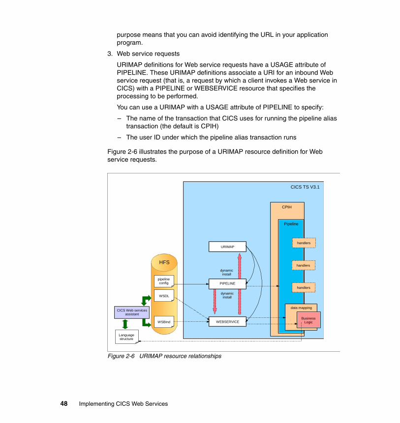
purpose means that you can avoid identifying the URL in your application program.
3. Web service requests
URIMAP definitions for Web service requests have a USAGE attribute of PIPELINE. These URIMAP definitions associate a URI for an inbound Web service request (that is, a request by which a client invokes a Web service in CICS) with a PIPELINE or WEBSERVICE resource that specifies the processing to be performed.
You can use a URIMAP with a USAGE attribute of PIPELINE to specify:
– The name of the transaction that CICS uses for running the pipeline alias transaction (the default is CPIH)
– The user ID under which the pipeline alias transaction runs
Figure 2-6 illustrates the purpose of a URIMAP resource definition for Web service requests.
Figure 2-6 URIMAP resource relationships
pipelineconfig
WSBind
WSDL
HFS
CICS TS V3.1
CPIH
Pipeline
data mapping
BusinessLogic
handlersURIMAP
PIPELINE
WEBSERVICE
dynamicinstall
dynamicinstall
Languagestructure
CICS Web services assistant
handlers
handlers
48 Implementing CICS Web Services
You can create URIMAP resource definitions in the following ways:
� Use the CEDA transaction
� Use the DFHCSDUP batch utility
� Use CICSPlex® SM Business Application Services
� Use the EXEC CICS CREATE URIMAP command
When you install a PIPELINE resource, or when you issue a PERFORM PIPELINE SCAN command (using CEMT or the CICS system programming interface), CICS scans the directory specified in the PIPELINE’s WSDIR attribute (the pickup directory), and creates URIMAP and WEBSERVICE resources dynamically. For each Web service binding file in the directory, that is, for each file with the wsbind suffix, CICS installs a WEBSERVICE and a URIMAP if one does not already exist. Existing resources are replaced if the information in the binding file is newer than the existing resources.
2.4.2 PIPELINE
A PIPELINE resource definition provides information about the message handlers that will act on a service request and on the response. The information about the message handlers is supplied indirectly; the PIPELINE definition specifies the name of an HFS file, called the pipeline configuration file, which contains an XML description of the message handlers and their configuration.
The most important attributes of the PIPELINE definition are as follows:
� WSDIR
The WSDIR attribute specifies the name of the Web service binding directory (also known as the pickup directory). The Web service binding directory contains Web service binding files that are associated with the PIPELINE, and that are to be installed automatically by the CICS scanning mechanism. When the PIPELINE definition is installed, CICS scans the directory and automatically installs any Web service binding files it finds there.
If you specify a value for the WSDIR attribute, it must refer to a valid HFS directory to which the CICS region has at least read access. If this is not the case, any attempt to install the PIPELINE resource will fail.
If you do not specify a value for WSDIR, no automatic scan takes place on installation of the PIPELINE, and PERFORM PIPELINE SCAN commands will fail.
Note: If you allow CICS to install the URIMAP resource dynamically, you cannot use the URIMAP definition to specify either the name of the transaction or the user ID under which the pipeline will run.
Chapter 2. CICS support for Web services 49
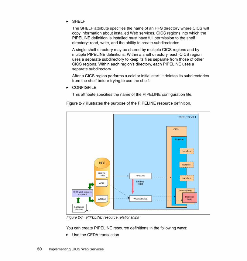
� SHELF
The SHELF attribute specifies the name of an HFS directory where CICS will copy information about installed Web services. CICS regions into which the PIPELINE definition is installed must have full permission to the shelf directory: read, write, and the ability to create subdirectories.
A single shelf directory may be shared by multiple CICS regions and by multiple PIPELINE definitions. Within a shelf directory, each CICS region uses a separate subdirectory to keep its files separate from those of other CICS regions. Within each region’s directory, each PIPELINE uses a separate subdirectory.
After a CICS region performs a cold or initial start, it deletes its subdirectories from the shelf before trying to use the shelf.
� CONFIGFILE
This attribute specifies the name of the PIPELINE configuration file.
Figure 2-7 illustrates the purpose of the PIPELINE resource definition.
Figure 2-7 PIPELINE resource relationships
You can create PIPELINE resource definitions in the following ways:
� Use the CEDA transaction
pipelineconfig
WSBind
WSDL
HFS
CICS TS V3.1
CPIH
Pipeline
data mapping
BusinessLogic
handlers
PIPELINE
WEBSERVICE
dynamicinstall
Languagestructure
CICS Web services assistant
handlers
handlers
50 Implementing CICS Web Services
� Use the DFHCSDUP batch utility
� Use CICSPlex SM Business Application Services
� Use the EXEC CICS CREATE PIPELINE command
Pipeline configuration fileWhen CICS processes a Web service request, it uses a pipeline of one or more message handlers to handle the request. The configuration of a pipeline used to handle a Web service request is specified in an XML document, known as a pipeline configuration file. Use a suitable XML editor or text editor to work with your pipeline configuration files. The exact configuration of the pipeline will depend upon the specific needs of the application.
There are two kinds of pipeline configuration files: one describes the configuration of a service provider pipeline, the other describes the configuration of a service requester pipeline. Each is defined by its own schema, and each has a different root element. The root element for a provider pipeline is <provider_pipeline>, while the root element for a requester pipeline is <requester_pipeline>.
The immediate child elements of the <provider_pipeline> element are:
� A mandatory <service> element, which specifies the message handlers that are invoked for every request, including the terminal message handler. The terminal message handler is the last handler in the pipeline.
� An optional <transport> element, which specifies message handlers that are selected at run time based upon the resources that are being used for the message transport. For example, for the HTTP transport, you can specify that CICS should invoke the message handler only when the port on which the request was received is defined on a specific TCPIPSERVICE definition. For the WebSphere MQ transport, you can specify that CICS should invoke the message handler only when the inbound message arrives at a specific message queue.
� An optional <apphandler> element, which specifies the name of the program that the terminal message handler will link to by default, that is, the name of the target application program (or wrapper program) that provides the service. Message handlers can specify a different program at run time by using the DFHWS-APPHANDLER container, so the name coded here is not always the program that is linked to.
Important: When you use DFHLS2WS or DFHWS2LS to deploy your service provider, you must specify DFHPITP as the target program. DFHPITP will get the name of your target application program (or wrapper program) from the wsbind file.
Chapter 2. CICS support for Web services 51
The <apphandler> element is used when the last message handler in the pipeline (the terminal handler) is one of the CICS-supplied SOAP message handlers.
If you do not code an <apphandler> element, one of the message handlers must use the DFHWS-APPHANDLER container to specify the name of the program.
� An optional <service_parameter_list> element, which contains parameters that CICS will make available to the message handlers in the pipeline via container DFH-SERVICEPLIST.
Example 2-1 shows the sample service provider pipeline configuration file basicsoap11provider.xml.
Example 2-1 Configuration file for service provider
<?xml version="1.0" encoding="EBCDIC-CP-US"?> <provider_pipeline xmlns="http://www.ibm.com/software/htp/cics/pipeline" xmlns:xsi="http://www.w3.org/2001/XMLSchema-instance" xsi:schemaLocation="http://www.ibm.com/software/htp/cics/pipelineprovider.xsd "> <service> <terminal_handler> <cics_soap_1.1_handler/> </terminal_handler> </service> <apphandler>DFHPITP</apphandler> </provider_pipeline>
The immediate sub-elements of a <requester_pipeline> element are:
� An optional <service> element, which specifies the message handlers that are invoked for every request
� An optional <transport> element, which specifies message handlers that are selected at run time, based upon the resources that are being used for the message transport
� An optional <service_parameter_list> element, which contains parameters that CICS will make available to the message handlers in the pipeline via container DFH-SERVICEPLIST
Important: A pipeline can be configured to support SOAP 1.1 or SOAP 1.2. Within your CICS system, you can have many pipelines, some of which support SOAP 1.1 and some of which support SOAP 1.2.
52 Implementing CICS Web Services
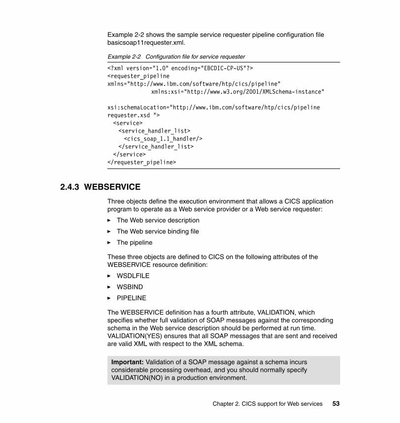
Example 2-2 shows the sample service requester pipeline configuration file basicsoap11requester.xml.
Example 2-2 Configuration file for service requester
<?xml version="1.0" encoding="EBCDIC-CP-US"?> <requester_pipeline xmlns="http://www.ibm.com/software/htp/cics/pipeline" xmlns:xsi="http://www.w3.org/2001/XMLSchema-instance" xsi:schemaLocation="http://www.ibm.com/software/htp/cics/pipeline requester.xsd "> <service> <service_handler_list> <cics_soap_1.1_handler/> </service_handler_list> </service> </requester_pipeline>
2.4.3 WEBSERVICE
Three objects define the execution environment that allows a CICS application program to operate as a Web service provider or a Web service requester:
� The Web service description
� The Web service binding file
� The pipeline
These three objects are defined to CICS on the following attributes of the WEBSERVICE resource definition:
� WSDLFILE
� WSBIND
� PIPELINE
The WEBSERVICE definition has a fourth attribute, VALIDATION, which specifies whether full validation of SOAP messages against the corresponding schema in the Web service description should be performed at run time. VALIDATION(YES) ensures that all SOAP messages that are sent and received are valid XML with respect to the XML schema.
Important: Validation of a SOAP message against a schema incurs considerable processing overhead, and you should normally specify VALIDATION(NO) in a production environment.
Chapter 2. CICS support for Web services 53
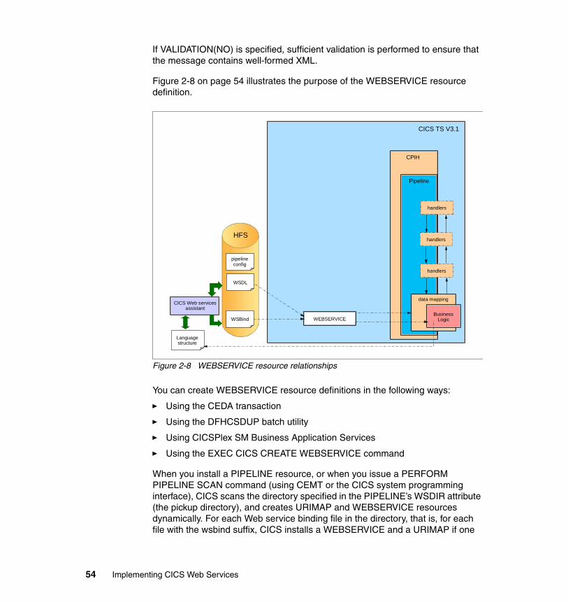
If VALIDATION(NO) is specified, sufficient validation is performed to ensure that the message contains well-formed XML.
Figure 2-8 on page 54 illustrates the purpose of the WEBSERVICE resource definition.
Figure 2-8 WEBSERVICE resource relationships
You can create WEBSERVICE resource definitions in the following ways:
� Using the CEDA transaction
� Using the DFHCSDUP batch utility
� Using CICSPlex SM Business Application Services
� Using the EXEC CICS CREATE WEBSERVICE command
When you install a PIPELINE resource, or when you issue a PERFORM PIPELINE SCAN command (using CEMT or the CICS system programming interface), CICS scans the directory specified in the PIPELINE’s WSDIR attribute (the pickup directory), and creates URIMAP and WEBSERVICE resources dynamically. For each Web service binding file in the directory, that is, for each file with the wsbind suffix, CICS installs a WEBSERVICE and a URIMAP if one
pipelineconfig
WSBind
WSDL
HFS
CICS TS V3.1
CPIH
Pipeline
data mapping
BusinessLogic
handlers
WEBSERVICE
Languagestructure
CICS Web services assistant
handlers
handlers
54 Implementing CICS Web Services
does not already exist. Existing resources are replaced if the information in the binding file is newer than the existing resources.
The CEMT INQUIRE WEBSERVICE command is used to obtain information about a WEBSERVICE resource definition. The data returned depends on the type of Web service.
Web service binding file A Web services description contains abstract representations of the input and output messages used by the service. When a service provider or service requester application executes, CICS needs information about how the content of the messages maps to the data structures used by the application. This information is held in a Web service binding file.
Web services binding files are created:
� By utility program DFHWS2LS when language structures are generated from WSDL
� By utility program DFHLS2WS when WSDL is generated from a language structure
At run time, CICS uses information in the Web service binding file to perform the mapping between application data structures and SOAP messages.
2.4.4 TCPIPSERVICE
A TCPIPSERVICE definition is required in a service provider that uses the HTTP transport, and contains information about the port on which inbound requests are received.
You can create TCPIPSERVICE resource definitions in the following ways:
� Using the CEDA transaction
� Using the DFHCSDUP batch utility
� Using CICSPlex SM Business Application Services
� Using the EXEC CICS CREATE TCPIPSERVICE command
2.4.5 Resources checklist
The relationships between CICS Web services definitions are shown in Figure 2-9 on page 56.
Chapter 2. CICS support for Web services 55
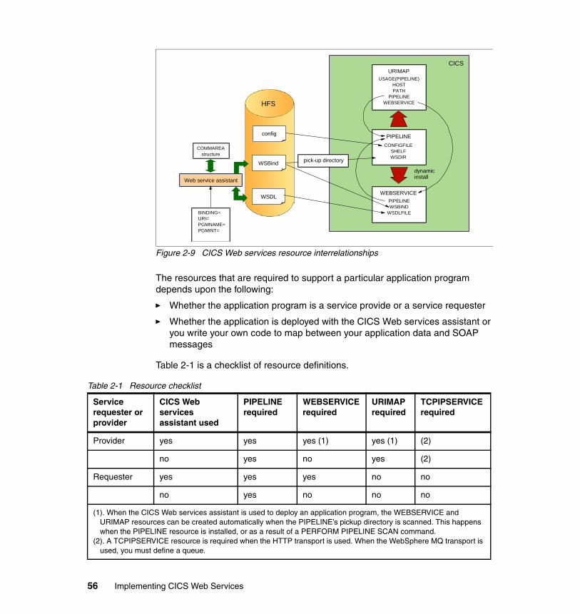
Figure 2-9 CICS Web services resource interrelationships
The resources that are required to support a particular application program depends upon the following:
� Whether the application program is a service provide or a service requester
� Whether the application is deployed with the CICS Web services assistant or you write your own code to map between your application data and SOAP messages
Table 2-1 is a checklist of resource definitions.
Table 2-1 Resource checklist
dynamicinstall
CICSURIMAP
USAGE(PIPELINE)HOSTPATH
PIPELINEWEBSERVICE
PIPELINECONFIGFILE
SHELFWSDIR
WEBSERVICEPIPELINEWSBIND
WSDLFILE
config
WSBind
WSDL
pick-up directory
HFS
Web service assistant
COMMAREAstructure
BINDING=URI=PGMNAME=PGMINT=
Service requester or provider
CICS Web services assistant used
PIPELINE required
WEBSERVICE required
URIMAP required
TCPIPSERVICE required
Provider yes yes yes (1) yes (1) (2)
no yes no yes (2)
Requester yes yes yes no no
no yes no no no
(1). When the CICS Web services assistant is used to deploy an application program, the WEBSERVICE and URIMAP resources can be created automatically when the PIPELINE’s pickup directory is scanned. This happens when the PIPELINE resource is installed, or as a result of a PERFORM PIPELINE SCAN command.
(2). A TCPIPSERVICE resource is required when the HTTP transport is used. When the WebSphere MQ transport is used, you must define a queue.
56 Implementing CICS Web Services
2.5 Message handlers
When you want to perform specialized processing on the messages that flow between a service requester and a service provider, and CICS does not supply a message handler that meets your needs, you will need to supply your own.
The message handler interface lets you perform the following tasks in a message handler program:
� Examine the contents of an XML request or response, without changing it
� Change the contents of an XML request or response
� In a non-terminal message handler, pass an XML request or response to the next message handler in the pipeline
� In a terminal message handler (the last handler in the pipeline) call an application program, and generate a response
� In the request phase of the pipeline, force a transition to the response phase, by absorbing the request, and generating a response
� Handle errors
Message handlers can be used for specific custom functions like:
� Logging requests
� Changing the “context” of a request, for example, changing the name of the transaction that CICS uses for running the pipeline alias transaction
Message handlers use channels and containers to interact with one another, and with the system (see “Channels and containers” on page 59).
2.5.1 SOAP message handlers
CICS provides SOAP message handlers that you can include in your pipeline to process SOAP 1.1 and SOAP 1.2 messages. You can use the SOAP message handlers in a service requester or in a service provider pipeline.
On input, the SOAP message handlers parse inbound SOAP messages, and extract the SOAP <Body> element for use by your application program. On output, the handlers construct the complete SOAP message, using the <Body> element that your application provides.
If you use SOAP headers in your messages, the SOAP handlers can invoke user-written header processing programs that allow you to process the SOAP headers on inbound messages, and to add them to outbound messages. For
Chapter 2. CICS support for Web services 57
example, a header processing program could check security information in a SOAP header or SOAP body.
A SOAP message handler, and optional header processing programs, are specified in the pipeline configuration file using the <cics_soap_1.1_handler> and the <cics_soap_1.2_handler> elements and their sub-elements.
Typically, you will need just one SOAP message handler in a pipeline. However, there are some situations where more than one is needed. For example, you can ensure that SOAP headers are processed in a particular sequence by defining multiple SOAP message handlers.
SOAPFAULT commandsSOAP message handlers and header processing programs can use three API commands which are new in CICS TS V3.1 to manage SOAP faults:
� EXEC CICS SOAPFAULT CREATE
Use this command to create a SOAP fault. If a SOAP fault already exists in the context of the SOAP message that is being processed by the message handler, the existing fault is overwritten.
� EXEC CICS SOAPFAULT ADD
Use this command to add either of the following items to a SOAPFAULT object that was created with an earlier SOAPFAULT CREATE command:
– A subcode
– A fault string for a particular national language
If the fault already contains a fault string for the language, then this command replaces the fault string for that language. In SOAP 1.1, only the fault string for the original language is used.
� EXEC CICS SOAPFAULT DELETE
Use this command to delete a SOAPFAULT object that was created with an earlier SOAPFAULT CREATE command.
These commands require information that is held in containers on the channel of the CICS-supplied SOAP message handler. To use these commands, you must have access to the channel. Only the following types of programs have this access:
Tip: Do not confuse header processing programs with message handlers. A header processing program can only be invoked by a CICS-supplied SOAP message handler to process a specific kind of SOAP header.
58 Implementing CICS Web Services
� Programs that are invoked directly from a CICS-supplied SOAP message handler, including SOAP header processing programs.
� Programs deployed with the Web services assistant that have a channel interface. Programs with a COMMAREA interface do not have access to the channel.
Many of the options on the SOAPFAULT CREATE and SOAPFAULT ADD commands apply to SOAP 1.1 and SOAP 1.2 faults, although their behavior is slightly different for each level of SOAP. Other options apply to one SOAP level or the other, but not to both, and if you specify any of them when the message uses a different level of SOAP, the command will raise an INVREQ condition. To help you determine which SOAP level applies to the message, container DFHWS-SOAPLEVEL contains a binary fullword with one of the following values:
– 1 - The request or response is a SOAP 1.1 message.
– 2 - The request or response is a SOAP 1.2 message.
– 10 - The request or response is not a SOAP message.
2.5.2 Channels and containers
Channels and containers are new resources in CICS TS V3.1 that provide the capability to pass data from one application to another application.
� A channel is a logical resource that must contain one or more containers.
� A container is a named block of data designed for passing information between programs.
The major advantage of using channels and containers compared to using a COMMAREA is that the length of a container can exceed the 32 KB limit for COMMAREA data. CICS uses channels and containers to pass data between the message handlers of a pipeline.
All programs that are used as message handlers are invoked with the same channel interface. The channel holds a number of containers. The containers can be categorized as:
� Control containers
These are essential to the operation of the pipeline. Message handlers can use the control containers to modify the sequence in which the message handlers are processed.
� Context containers
In some situations, message handler programs need information about the context in which they are invoked. CICS provides this information in a set of context containers that are passed to the programs. Some of the context
Chapter 2. CICS support for Web services 59
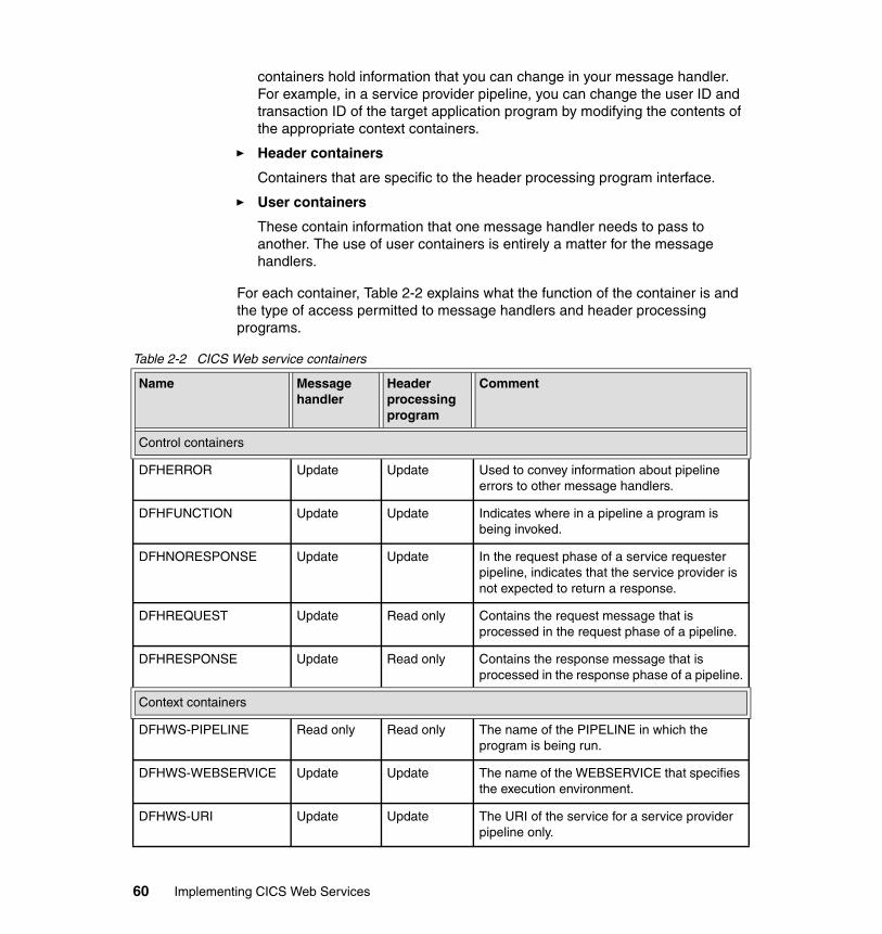
containers hold information that you can change in your message handler. For example, in a service provider pipeline, you can change the user ID and transaction ID of the target application program by modifying the contents of the appropriate context containers.
� Header containers
Containers that are specific to the header processing program interface.
� User containers
These contain information that one message handler needs to pass to another. The use of user containers is entirely a matter for the message handlers.
For each container, Table 2-2 explains what the function of the container is and the type of access permitted to message handlers and header processing programs.
Table 2-2 CICS Web service containers
Name Message handler
Header processing program
Comment
Control containers
DFHERROR Update Update Used to convey information about pipeline errors to other message handlers.
DFHFUNCTION Update Update Indicates where in a pipeline a program is being invoked.
DFHNORESPONSE Update Update In the request phase of a service requester pipeline, indicates that the service provider is not expected to return a response.
DFHREQUEST Update Read only Contains the request message that is processed in the request phase of a pipeline.
DFHRESPONSE Update Read only Contains the response message that is processed in the response phase of a pipeline.
Context containers
DFHWS-PIPELINE Read only Read only The name of the PIPELINE in which the program is being run.
DFHWS-WEBSERVICE Update Update The name of the WEBSERVICE that specifies the execution environment.
DFHWS-URI Update Update The URI of the service for a service provider pipeline only.
60 Implementing CICS Web Services
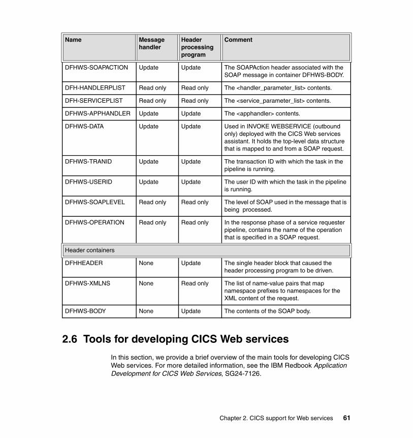
2.6 Tools for developing CICS Web services
In this section, we provide a brief overview of the main tools for developing CICS Web services. For more detailed information, see the IBM Redbook Application Development for CICS Web Services, SG24-7126.
DFHWS-SOAPACTION Update Update The SOAPAction header associated with the SOAP message in container DFHWS-BODY.
DFH-HANDLERPLIST Read only Read only The <handler_parameter_list> contents.
DFH-SERVICEPLIST Read only Read only The <service_parameter_list> contents.
DFHWS-APPHANDLER Update Update The <apphandler> contents.
DFHWS-DATA Update Update Used in INVOKE WEBSERVICE (outbound only) deployed with the CICS Web services assistant. It holds the top-level data structure that is mapped to and from a SOAP request.
DFHWS-TRANID Update Update The transaction ID with which the task in the pipeline is running.
DFHWS-USERID Update Update The user ID with which the task in the pipeline is running.
DFHWS-SOAPLEVEL Read only Read only The level of SOAP used in the message that is being processed.
DFHWS-OPERATION Read only Read only In the response phase of a service requester pipeline, contains the name of the operation that is specified in a SOAP request.
Header containers
DFHHEADER None Update The single header block that caused the header processing program to be driven.
DFHWS-XMLNS None Read only The list of name-value pairs that map namespace prefixes to namespaces for the XML content of the request.
DFHWS-BODY None Update The contents of the SOAP body.
Name Message handler
Header processing program
Comment
Chapter 2. CICS support for Web services 61
2.6.1 CICS Web services assistant
The CICS Web services assistant is a set of batch utilities that can help you transform existing CICS applications into Web services and enable CICS applications to use Web services provided by external providers. The assistant supports rapid deployment of CICS applications for use in service providers and service requesters, with minimal programming effort.
When you use the Web services assistant for CICS, you do not have to write your own code for parsing inbound messages and for constructing outbound messages; CICS maps data between the body of a SOAP message and the application program’s data structure.
Resource definitions are, for the most part, generated and installed automatically. You do have to define PIPELINE resources, but you can, in many cases, use one of the pipeline configuration files that CICS provides.
The assistant can create a WSDL document from a simple language structure, or a language structure from an existing WSDL document, and supports COBOL, C/C++, and PL/I. It also generates information used to enable automatic run-time conversion of the SOAP messages to containers and COMMAREAs, and vice versa.
However, the assistant cannot deal with every possibility, and there are times when you will need to take a different approach. For example:
� You don’t want to use SOAP messages.
If you prefer to use a non-SOAP protocol for your messages, you can do so. However, your application programs will be responsible for parsing inbound messages, and constructing outbound messages.
� You want to use SOAP messages, but don’t want CICS to parse them.
For an inbound message, the assistant maps the SOAP body to an application data structure. In some applications, you may want to parse the SOAP body yourself.
� The CICS Web services assistant does not support your application’s data structure.
Although the CICS Web services assistant supports the most common data types and structures, there are some that are not supported. For example, OCCURS DEPENDING ON and REDEFINES on data description entries are not supported. For full details on the data types and structures supported by the CICS Web Services assistant, see the CICS Web Services Guide (SC34-6458).
62 Implementing CICS Web Services
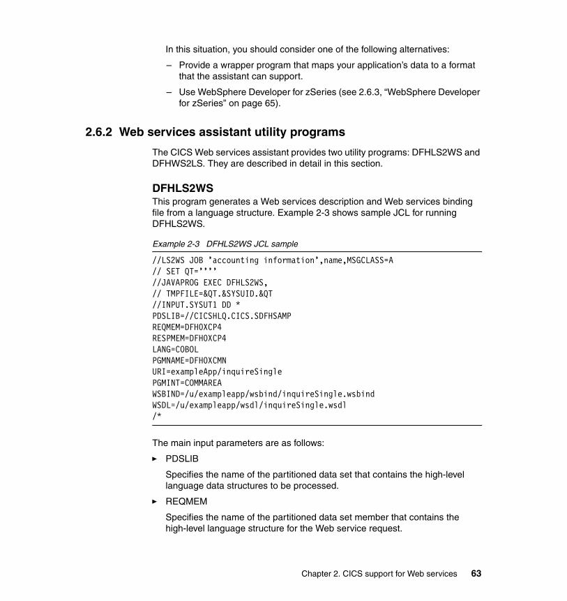
In this situation, you should consider one of the following alternatives:
– Provide a wrapper program that maps your application’s data to a format that the assistant can support.
– Use WebSphere Developer for zSeries (see 2.6.3, “WebSphere Developer for zSeries” on page 65).
2.6.2 Web services assistant utility programs
The CICS Web services assistant provides two utility programs: DFHLS2WS and DFHWS2LS. They are described in detail in this section.
DFHLS2WS This program generates a Web services description and Web services binding file from a language structure. Example 2-3 shows sample JCL for running DFHLS2WS.
Example 2-3 DFHLS2WS JCL sample
//LS2WS JOB ’accounting information’,name,MSGCLASS=A // SET QT=’’’’ //JAVAPROG EXEC DFHLS2WS, // TMPFILE=&QT.&SYSUID.&QT //INPUT.SYSUT1 DD * PDSLIB=//CICSHLQ.CICS.SDFHSAMP REQMEM=DFH0XCP4 RESPMEM=DFH0XCP4 LANG=COBOL PGMNAME=DFH0XCMN URI=exampleApp/inquireSingle PGMINT=COMMAREA WSBIND=/u/exampleapp/wsbind/inquireSingle.wsbind WSDL=/u/exampleapp/wsdl/inquireSingle.wsdl /*
The main input parameters are as follows:
� PDSLIB
Specifies the name of the partitioned data set that contains the high-level language data structures to be processed.
� REQMEM
Specifies the name of the partitioned data set member that contains the high-level language structure for the Web service request.
Chapter 2. CICS support for Web services 63
– For a service provider, the Web service request is the input to the application program.
– For a service requester, the Web service request is the output from the application program.
� RESPMEM
Specifies the name of the partitioned data set member that contains the high-level language structure for the Web service response:
– For a service provider, the Web service response is the output from the application program.
– For a service requester, the Web service response is the input to the application program.
� LANG
Specifies the language of the language structure to be created.
� PGMNAME
Specifies the name of the target CICS application program that is being exposed as a Web service.
� URI
In a service provider, this parameter specifies the relative URI that a client will use to access the Web service. CICS uses the value specified when it generates a URIMAP resource from the Web service binding file created by DFHLS2WS. The parameter specifies the path component of the URI to which the URIMAP definition applies.
� PGMINT
For a service provider, specifies how CICS passes data to the target application program (using a COMMAREA or a channel).
� WSBIND
Specifies the HFS name of the Web service binding file.
� WSDL
Specifies the HFS name of the Web service description file.
DFHWS2LS This program generates a language structure and Web services binding file from a Web services description. Example 2-4 shows sample JCL for running DFHWS2LS.
Example 2-4 DFHWS2LS JCL sample
//WS2LS JOB ’accounting information’,name,MSGCLASS=A // SET QT=’’’’
64 Implementing CICS Web Services

//JAVAPROG EXEC DFHWS2LS,// TMPFILE=&QT.&SYSUID.&QT //INPUT.SYSUT1 DD * PDSLIB=//CICSHLQ.CICS.SDFHSAMP REQMEM=CPYBK1 RESPMEM=CPYBK2 LANG=COBOL PGMNAME=DFH0XCMN URI=exampleApp/inquireSingle PGMINT=COMMAREA WSBIND=/u/exampleapp/wsbind/inquireSingle.wsbind WSDL=/u/exampleapp/wsdl/inquireSingle.wsdl /*
2.6.3 WebSphere Developer for zSeries
WebSphere Developer for zSeries V6 is based on the IBM Rational® Software Development Platform and facilitates the development of both Java- and z/OS-based applications. It includes capabilities that make traditional z/OS mainframe development, Web development, and integrated composite development faster and more efficient. In particular, WebSphere Developer contains tools that support the development of Web services and the XML enablement of existing CICS COBOL applications.
The XML Services for the Enterprise (XSE) capability of WebSphere Developer provides tools that let you adapt COBOL-based applications so that they can consume and produce XML messages. XSE supports the creation of driver programs that work with existing CICS (or IMS™) applications.
The Web Services Enablement wizard is the XSE tool that supports the bottom-up approach for creating Web services based on existing CICS COBOL programs. It takes as input the COMMAREA copybook. The XML structure and data types are then derived from the COBOL data declarations. Based on these, the Web Services Enablement wizard generates the set of artifacts shown in Figure 2-10 on page 66.
Chapter 2. CICS support for Web services 65
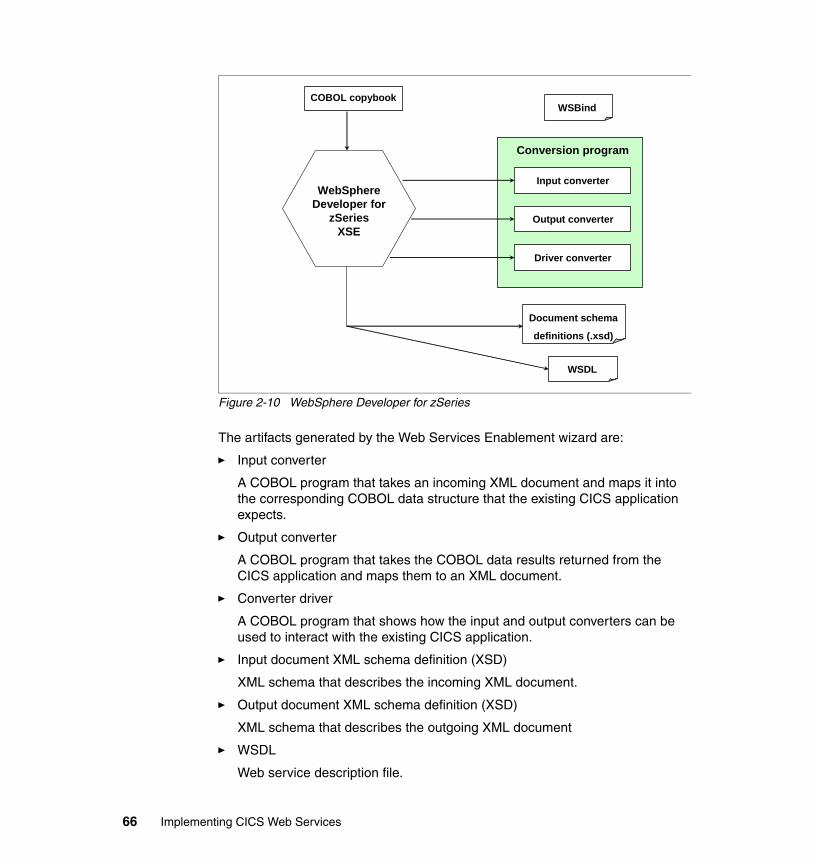
Figure 2-10 WebSphere Developer for zSeries
The artifacts generated by the Web Services Enablement wizard are:
� Input converter
A COBOL program that takes an incoming XML document and maps it into the corresponding COBOL data structure that the existing CICS application expects.
� Output converter
A COBOL program that takes the COBOL data results returned from the CICS application and maps them to an XML document.
� Converter driver
A COBOL program that shows how the input and output converters can be used to interact with the existing CICS application.
� Input document XML schema definition (XSD)
XML schema that describes the incoming XML document.
� Output document XML schema definition (XSD)
XML schema that describes the outgoing XML document
� WSDL
Web service description file.
COBOL copybook
Input converter
Conversion program
Output converter
Driver converter
WSBind
Document schema
definitions (.xsd)
WSDL
WebSphereDeveloper for
zSeries XSE
66 Implementing CICS Web Services
� WSBind
Web service binding file.
For additional information visit the WebSphere Developer for zSeries Web site at:
http://www.ibm.com/software/awdtools/devzseries/
2.7 Catalog manager example application
The CICS catalog manager example application is a COBOL application designed to illustrate best practice when connecting CICS applications to external clients and servers.
The example is constructed around a simple sales catalog and order processing application, in which the end user can perform these functions:
� List the items in a catalog (implemented as a VSAM file)
� Inquire on individual items in the catalog
� Order items from the catalog
The base application has a 3270 user interface, but the modular structure, with well-defined interfaces between the components, makes it possible to add further components. In particular, the application comes with Web services support, which is designed to illustrate how you can extend an existing application into the Web services environment.
2.7.1 The base application
Figure 2-11 on page 68 shows the structure of the base application.
Chapter 2. CICS support for Web services 67
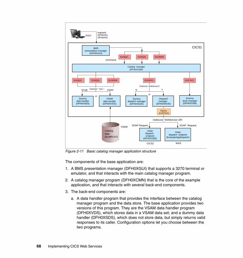
Figure 2-11 Basic catalog manager application structure
The components of the base application are:
1. A BMS presentation manager (DFH0XGUI) that supports a 3270 terminal or emulator, and that interacts with the main catalog manager program.
2. A catalog manager program (DFH0XCMN) that is the core of the example application, and that interacts with several back-end components.
3. The back-end components are:
a. A data handler program that provides the interface between the catalog manager program and the data store. The base application provides two versions of this program. They are the VSAM data handler program (DFH0XVDS), which stores data in a VSAM data set; and a dummy data handler (DFH0XSDS), which does not store data, but simply returns valid responses to its caller. Configuration options let you choose between the two programs.
BMSpresentation manager
(DFH0XGUI)
Catalog manager(DFH0XCMN)
commarea01INQC.. 01INQS. 01ORDR.
.. ...
.. ...01INQC.. 01INQS. 01ORDR.
Dummydata handler(DFH0XSDS)
VSAMdata handler(DFH0XVDS)
Dummydispatch manager
(DFH0XSOD)
Dispatchmanager
(DFH0XWOD)
Dummystock manager(DFH0XSSM)
mapsetsDFH0XS1DFH0XS2
EGUI
Datastore Type =STUB VSAM
or
CICS1
.. ..01DSPO.
or
N YOutbound WebService?
01STKO.
Pipeline (EXPIPE02)
Orderdispatch endpoint
(DFH0XODE)
Outbound WebService URI
SOAP RequestSOAP Request
Orderdispatch endpoint
(ExampleAppDispatch)
CICS2 WAS
Catalog data(EXMPCAT)
VSAM
68 Implementing CICS Web Services
b. A dispatch manager program that provides an interface for dispatching an order to a customer. Again, configuration options let you choose between the two versions of this program: DFHX0WOD is a service requester that invokes a remote order dispatch end point, and DFHX0SOD is a dummy program that simply returns valid responses to its caller. There are two equivalent order dispatch endpoints: DFH0XODE is a CICS service provider program; ExampleAppDispatchOrder.ear is an enterprise archive that can be deployed in WebSphere Application Server or similar environments.
c. A dummy stock manager program (DFH0XSSM) that returns valid responses to its caller, but takes no other action.
2.7.2 Web services support for the catalog example application
The Web services support extends the example application, providing a Web client front end and two versions of a Web services endpoint for the order dispatcher component.
The Web client front end and one version of the Web services endpoint are supplied as enterprise archives (EARs) that will run in the following environments:
� WebSphere Application Server Version 5 Release 1 or later
� WebSphere Studio Application Developer Version 5 Release 1 or later with a WebSphere unit test environment
� WebSphere Studio Enterprise Developer Version 5 Release 1 or later with a WebSphere unit test environment
The second version of the Web services endpoint is supplied as a CICS service provider application program (DFH0XODE).
Figure 2-12 on page 70 shows the structure of the Web services catalog application.
Chapter 2. CICS support for Web services 69
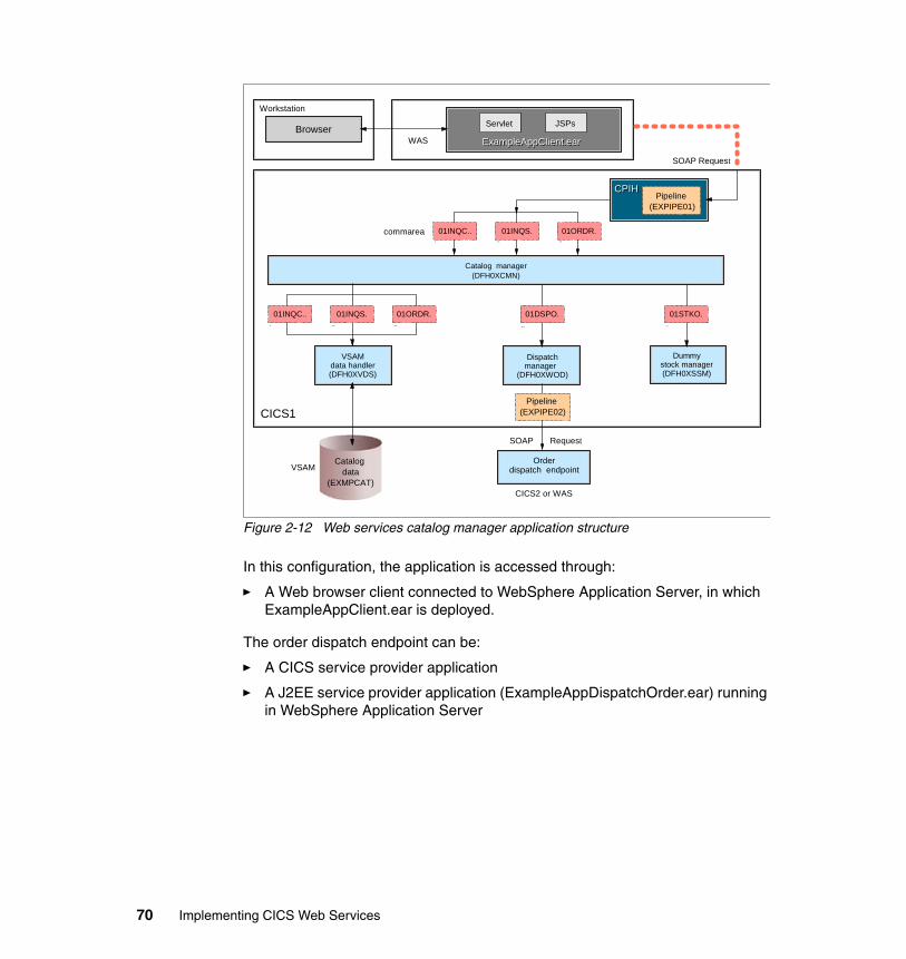
Figure 2-12 Web services catalog manager application structure
In this configuration, the application is accessed through:
� A Web browser client connected to WebSphere Application Server, in which ExampleAppClient.ear is deployed.
The order dispatch endpoint can be:
� A CICS service provider application
� A J2EE service provider application (ExampleAppDispatchOrder.ear) running in WebSphere Application Server
Catalog manager(DFH0XCMN)
commarea 01INQC.. 01INQS. 01ORDR... ...
.. ...01INQC.. 01INQS. 01ORDR.
VSAMdata handler(DFH0XVDS)
Dispatchmanager
(DFH0XWOD)
Dummystock manager(DFH0XSSM)
.. ..
Pipeline (EXPIPE02)
SOAP Request
Orderdispatch endpoint
CICS2 or WAS
Catalog data
(EXMPCAT)
CPIHCPIHPipeline
(EXPIPE01)
01DSPO. 01STKO.
CICS1
SOAP Request
VSAM
Servlet JSPs
ExampleAppClient.earExampleAppClient.earBrowser
Workstation
WAS
70 Implementing CICS Web Services
Part 2 Web service configuration
In this part we provide detailed instructions on how we configured our test CICS environment to support Web services using both HTTP and WebSphere MQ as transport mechanisms. We also describe how we deployed service requester and service provider applications in WebSphere Application Server, and how we used Web services to connect between WebSphere Application Server and CICS.
In chapter 5, we introduce the service integration bus and we outline the configuration steps for connecting to a CICS Web service via the bus.
Part 2
© Copyright IBM Corp. 2006. All rights reserved. 71
72 Implementing CICS Web Services
Chapter 3. Web services using HTTP
In this chapter we describe how we configured our test CICS environment to support Web services using HTTP as the transport mechanism.
3
© Copyright IBM Corp. 2006. All rights reserved. 73
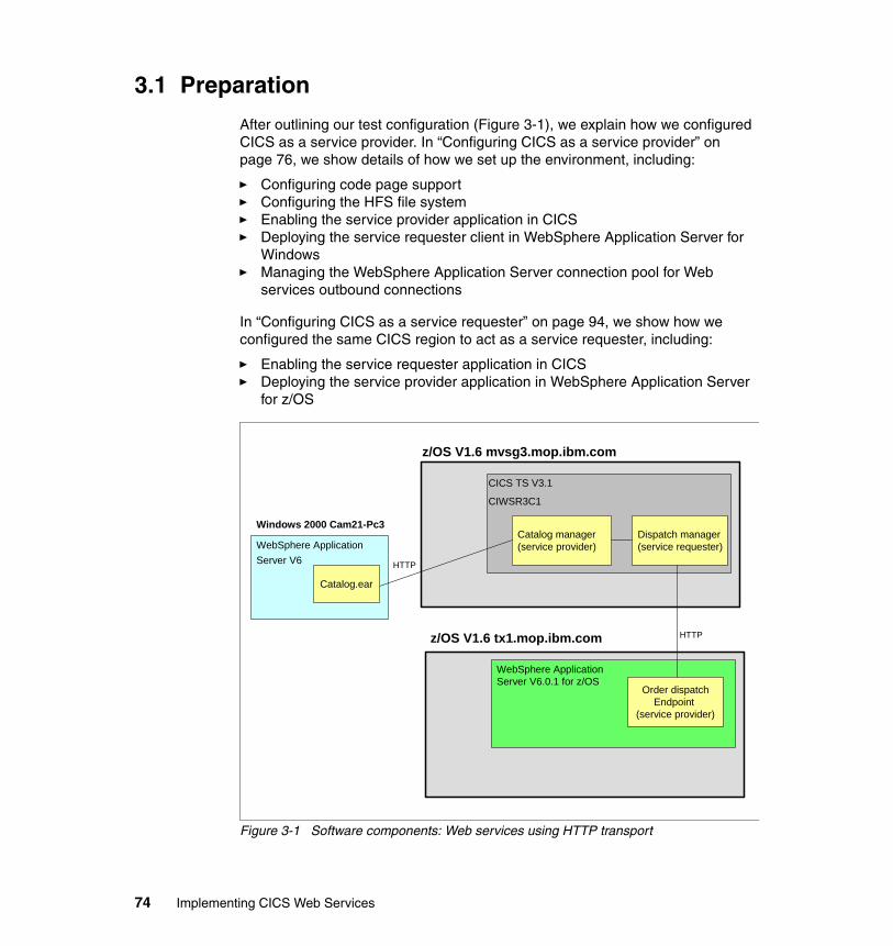
3.1 Preparation
After outlining our test configuration (Figure 3-1), we explain how we configured CICS as a service provider. In “Configuring CICS as a service provider” on page 76, we show details of how we set up the environment, including:
� Configuring code page support � Configuring the HFS file system� Enabling the service provider application in CICS� Deploying the service requester client in WebSphere Application Server for
Windows� Managing the WebSphere Application Server connection pool for Web
services outbound connections
In “Configuring CICS as a service requester” on page 94, we show how we configured the same CICS region to act as a service requester, including:
� Enabling the service requester application in CICS� Deploying the service provider application in WebSphere Application Server
for z/OS
Figure 3-1 Software components: Web services using HTTP transport
CICS TS V3.1
CIWSR3C1
WebSphere Application Server V6
Windows 2000 Cam21-Pc3
z/OS V1.6 mvsg3.mop.ibm.com
z/OS V1.6 tx1.mop.ibm.com
WebSphere Application Server V6.0.1 for z/OS
Catalog manager(service provider)
Dispatch manager(service requester)
Order dispatchEndpoint
(service provider)
Catalog.ear
HTTP
HTTP
74 Implementing CICS Web Services
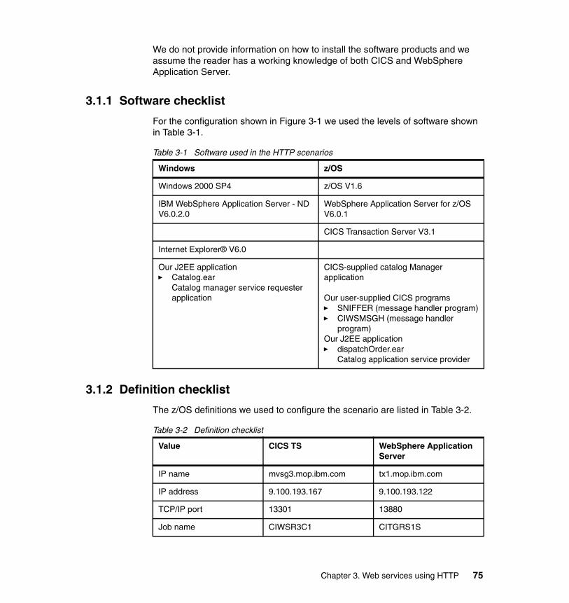
We do not provide information on how to install the software products and we assume the reader has a working knowledge of both CICS and WebSphere Application Server.
3.1.1 Software checklist
For the configuration shown in Figure 3-1 we used the levels of software shown in Table 3-1.
Table 3-1 Software used in the HTTP scenarios
3.1.2 Definition checklist
The z/OS definitions we used to configure the scenario are listed in Table 3-2.
Table 3-2 Definition checklist
Windows z/OS
Windows 2000 SP4 z/OS V1.6
IBM WebSphere Application Server - ND V6.0.2.0
WebSphere Application Server for z/OS V6.0.1
CICS Transaction Server V3.1
Internet Explorer® V6.0
Our J2EE application� Catalog.ear
Catalog manager service requester application
CICS-supplied catalog Manager application
Our user-supplied CICS programs� SNIFFER (message handler program)� CIWSMSGH (message handler
program) Our J2EE application� dispatchOrder.ear
Catalog application service provider
Value CICS TS WebSphere Application Server
IP name mvsg3.mop.ibm.com tx1.mop.ibm.com
IP address 9.100.193.167 9.100.193.122
TCP/IP port 13301 13880
Job name CIWSR3C1 CITGRS1S
Chapter 3. Web services using HTTP 75
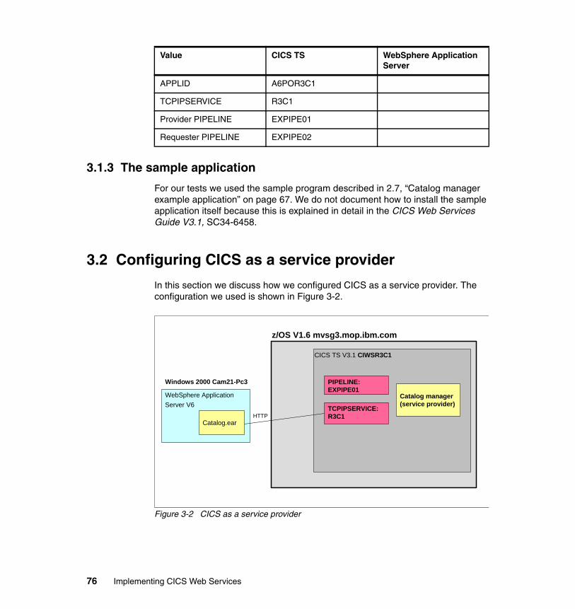
3.1.3 The sample application
For our tests we used the sample program described in 2.7, “Catalog manager example application” on page 67. We do not document how to install the sample application itself because this is explained in detail in the CICS Web Services Guide V3.1, SC34-6458.
3.2 Configuring CICS as a service provider
In this section we discuss how we configured CICS as a service provider. The configuration we used is shown in Figure 3-2.
Figure 3-2 CICS as a service provider
APPLID A6POR3C1
TCPIPSERVICE R3C1
Provider PIPELINE EXPIPE01
Requester PIPELINE EXPIPE02
Value CICS TS WebSphere Application Server
CICS TS V3.1 CIWSR3C1
WebSphere Application Server V6
Windows 2000 Cam21-Pc3
z/OS V1.6 mvsg3.mop.ibm.com
Catalog manager(service provider)
Catalog.ear
TCPIPSERVICE:R3C1
PIPELINE:EXPIPE01
HTTP
76 Implementing CICS Web Services
3.2.1 Configuring code page support
We configured our z/OS system to support conversions between the two coded character sets used by the example application; these are shown in Example 3-1.
Example 3-1 CCSID description
037 EBCDIC Group 1: USA, Canada (z/OS), Netherlands, Portugal,Brazil, Australia, New Zealand
1208 UTF-8 Level 3
To do this we added the statements shown in Example 3-2 to the conversion image for our z/OS system.
Example 3-2 Required conversions
CONVERSION 037,1208;CONVERSION 1208,037;
We used the SET UNI=31 z/OS command to activate the updated conversion image, where 31 is the suffix of the CUNUNIxx member of SYS1.PARMLIB.
For more information on code page support, see CICS Installation Guide V3.1, GC34-6426.
3.2.2 Configuring CICS
To enable CICS to receive Web service requests using HTTP we performed the following tasks:
� Updating CICS system initialization table (SIT) parameters
� Creating the HFS directories
� Configuring the TCPIPSERVICE resource definition
� Customizing the pipeline configuration file
� Writing a message handler program that changes the transaction ID
� Configuring the PIPELINE resource definition
Tip: With z/OS V1R7, the Unicode Services environment can be dynamically updated when a conversion service is requested. If the appropriate table needed for the service is not already loaded into storage, Unicode Services will load the table without requiring an IPL or disrupting the caller’s request. For more information see z/OS Support for Unicode: Unicode Services, SA22-7649-06.
Chapter 3. Web services using HTTP 77
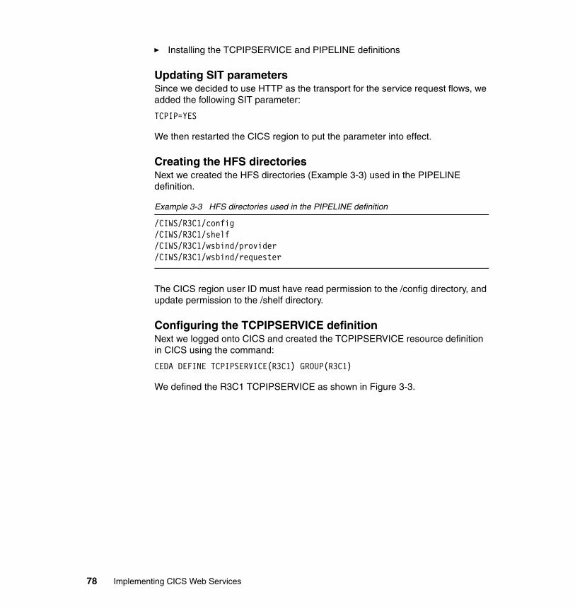
� Installing the TCPIPSERVICE and PIPELINE definitions
Updating SIT parametersSince we decided to use HTTP as the transport for the service request flows, we added the following SIT parameter:
TCPIP=YES
We then restarted the CICS region to put the parameter into effect.
Creating the HFS directoriesNext we created the HFS directories (Example 3-3) used in the PIPELINE definition.
Example 3-3 HFS directories used in the PIPELINE definition
/CIWS/R3C1/config/CIWS/R3C1/shelf/CIWS/R3C1/wsbind/provider/CIWS/R3C1/wsbind/requester
The CICS region user ID must have read permission to the /config directory, and update permission to the /shelf directory.
Configuring the TCPIPSERVICE definitionNext we logged onto CICS and created the TCPIPSERVICE resource definition in CICS using the command:
CEDA DEFINE TCPIPSERVICE(R3C1) GROUP(R3C1)
We defined the R3C1 TCPIPSERVICE as shown in Figure 3-3.
78 Implementing CICS Web Services
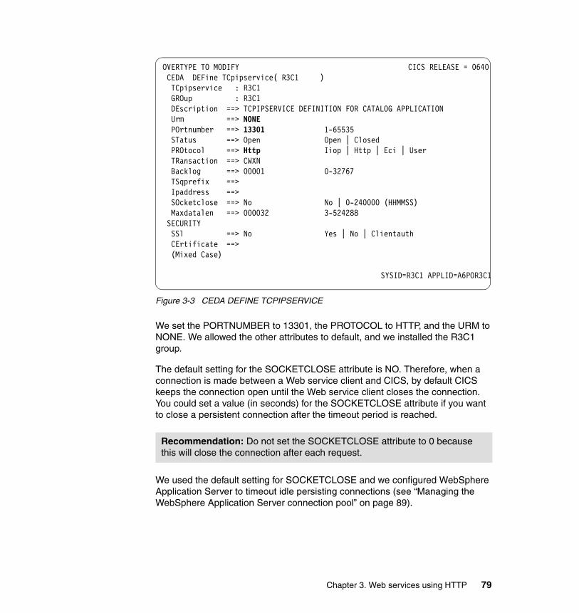
Figure 3-3 CEDA DEFINE TCPIPSERVICE
We set the PORTNUMBER to 13301, the PROTOCOL to HTTP, and the URM to NONE. We allowed the other attributes to default, and we installed the R3C1 group.
The default setting for the SOCKETCLOSE attribute is NO. Therefore, when a connection is made between a Web service client and CICS, by default CICS keeps the connection open until the Web service client closes the connection. You could set a value (in seconds) for the SOCKETCLOSE attribute if you want to close a persistent connection after the timeout period is reached.
We used the default setting for SOCKETCLOSE and we configured WebSphere Application Server to timeout idle persisting connections (see “Managing the WebSphere Application Server connection pool” on page 89).
Recommendation: Do not set the SOCKETCLOSE attribute to 0 because this will close the connection after each request.
OVERTYPE TO MODIFY CICS RELEASE = 0640 CEDA DEFine TCpipservice( R3C1 ) TCpipservice : R3C1 GROup : R3C1 DEscription ==> TCPIPSERVICE DEFINITION FOR CATALOG APPLICATION Urm ==> NONE POrtnumber ==> 13301 1-65535 STatus ==> Open Open | Closed PROtocol ==> Http Iiop | Http | Eci | User TRansaction ==> CWXN Backlog ==> 00001 0-32767 TSqprefix ==> Ipaddress ==> SOcketclose ==> No No | 0-240000 (HHMMSS) Maxdatalen ==> 000032 3-524288 SECURITY SSl ==> No Yes | No | Clientauth CErtificate ==> (Mixed Case)
SYSID=R3C1 APPLID=A6POR3C1
Chapter 3. Web services using HTTP 79
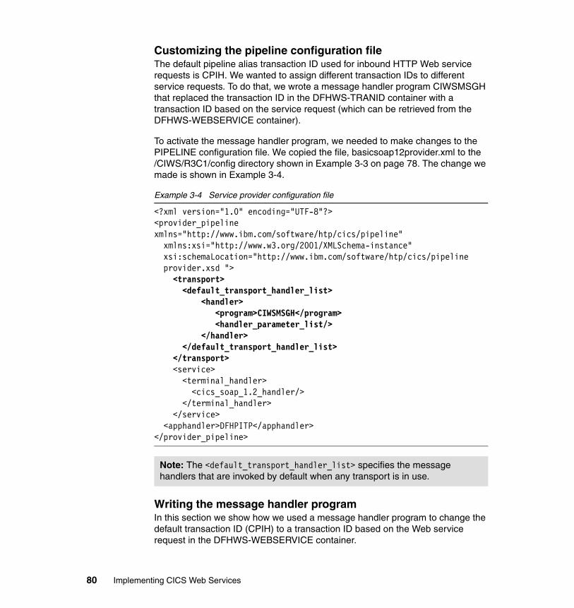
Customizing the pipeline configuration fileThe default pipeline alias transaction ID used for inbound HTTP Web service requests is CPIH. We wanted to assign different transaction IDs to different service requests. To do that, we wrote a message handler program CIWSMSGH that replaced the transaction ID in the DFHWS-TRANID container with a transaction ID based on the service request (which can be retrieved from the DFHWS-WEBSERVICE container).
To activate the message handler program, we needed to make changes to the PIPELINE configuration file. We copied the file, basicsoap12provider.xml to the /CIWS/R3C1/config directory shown in Example 3-3 on page 78. The change we made is shown in Example 3-4.
Example 3-4 Service provider configuration file
<?xml version="1.0" encoding="UTF-8"?><provider_pipeline xmlns="http://www.ibm.com/software/htp/cics/pipeline" xmlns:xsi="http://www.w3.org/2001/XMLSchema-instance" xsi:schemaLocation="http://www.ibm.com/software/htp/cics/pipeline
provider.xsd "> <transport> <default_transport_handler_list> <handler> <program>CIWSMSGH</program> <handler_parameter_list/> </handler>
</default_transport_handler_list> </transport> <service> <terminal_handler> <cics_soap_1.2_handler/> </terminal_handler> </service> <apphandler>DFHPITP</apphandler></provider_pipeline>
Writing the message handler programIn this section we show how we used a message handler program to change the default transaction ID (CPIH) to a transaction ID based on the Web service request in the DFHWS-WEBSERVICE container.
Note: The <default_transport_handler_list> specifies the message handlers that are invoked by default when any transport is in use.
80 Implementing CICS Web Services
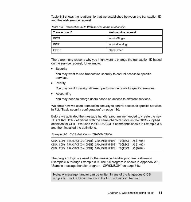
Table 3-3 shows the relationship that we established between the transaction ID and the Web service request.
Table 3-3 Transaction ID to Web service name relationship
There are many reasons why you might want to change the transaction ID based on the service request, for example:
� Security
You may want to use transaction security to control access to specific services.
� Priority
You may want to assign different performance goals to specific services.
� Accounting
You may need to charge users based on access to different services.
We show how we used transaction security to control access to specific services in 7.2, “Basic security configuration” on page 180.
Before we activated the message handler program we needed to create the new TRANSACTION definitions with the same characteristics as the CICS-supplied definition for CPIH. We used the CEDA COPY commands shown in Example 3-5 and then installed the definitions.
Example 3-5 CICS definitions - TRANSACTION
CEDA COPY TRANSACTION(CPIH) GROUP(DFHPIPE) TO(R3C1) AS(INQS)CEDA COPY TRANSACTION(CPIH) GROUP(DFHPIPE) TO(R3C1) AS(INQC)CEDA COPY TRANSACTION(CPIH) GROUP(DFHPIPE) TO(R3C1) AS(ORDR)
The program logic we used for the message handler program is shown in Example 3-6 through Example 3-9. The full program is shown in Appendix A.1, “Sample message handler program - CIWSMSGH” on page 346.
Transaction ID Web service request
INQS inquireSingle
INQC inquireCatalog
ORDR placeOrder
Note: A message handler can be written in any of the languages CICS supports. The CICS commands in the DPL subset can be used.
Chapter 3. Web services using HTTP 81
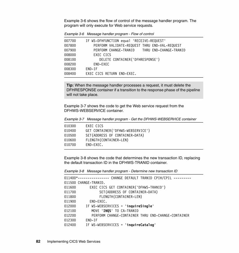
Example 3-6 shows the flow of control of the message handler program. The program will only execute for Web service requests.
Example 3-6 Message handler program - Flow of control
007700 IF WS-DFHFUNCTION equal 'RECEIVE-REQUEST' 007800 PERFORM VALIDATE-REQUEST THRU END-VAL-REQUEST 007900 PERFORM CHANGE-TRANID THRU END-CHANGE-TRANID 008000 EXEC CICS 008100 DELETE CONTAINER('DFHRESPONSE') 008200 END-EXEC 008300 END-IF 008400 EXEC CICS RETURN END-EXEC.
Example 3-7 shows the code to get the Web service request from the DFHWS-WEBSERVICE container.
Example 3-7 Message handler program - Get the DFHWS-WEBSERVICE container
010300 EXEC CICS010400 GET CONTAINER('DFHWS-WEBSERVICE') 010500 SET(ADDRESS OF CONTAINER-DATA) 010600 FLENGTH(CONTAINER-LEN) 010700 END-EXEC.
Example 3-8 shows the code that determines the new transaction ID, replacing the default transaction ID in the DFHWS-TRANID container.
Example 3-8 Message handler program - Determine new transaction ID
011400*---------------- CHANGE DEFAULT TRANID CPIH/CPIL ---------011500 CHANGE-TRANID. 011600 EXEC CICS GET CONTAINER('DFHWS-TRANID') 011700 SET(ADDRESS OF CONTAINER-DATA) 011800 FLENGTH(CONTAINER-LEN) 011900 END-EXEC. 012000 IF WS-WEBSERVICES = 'inquireSingle' 012100 MOVE 'INQS' TO CA-TRANID 012200 PERFORM CHANGE-CONTAINER THRU END-CHANGE-CONTAINER 012300 END-IF 012400 IF WS-WEBSERVICES = 'inquireCatalog'
Tip: When the message handler processes a request, it must delete the DFHRESPONSE container if a transition to the response phase of the pipeline will not take place.
82 Implementing CICS Web Services
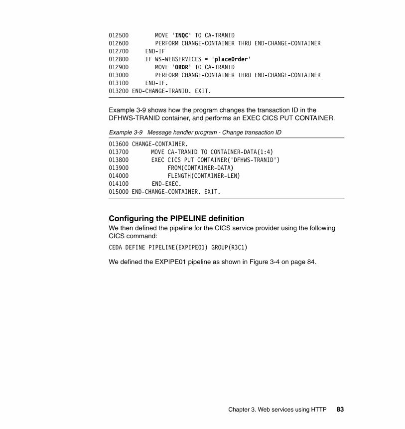
012500 MOVE 'INQC' TO CA-TRANID 012600 PERFORM CHANGE-CONTAINER THRU END-CHANGE-CONTAINER 012700 END-IF 012800 IF WS-WEBSERVICES = 'placeOrder' 012900 MOVE 'ORDR' TO CA-TRANID 013000 PERFORM CHANGE-CONTAINER THRU END-CHANGE-CONTAINER 013100 END-IF. 013200 END-CHANGE-TRANID. EXIT.
Example 3-9 shows how the program changes the transaction ID in the DFHWS-TRANID container, and performs an EXEC CICS PUT CONTAINER.
Example 3-9 Message handler program - Change transaction ID
013600 CHANGE-CONTAINER. 013700 MOVE CA-TRANID TO CONTAINER-DATA(1:4) 013800 EXEC CICS PUT CONTAINER('DFHWS-TRANID') 013900 FROM(CONTAINER-DATA) 014000 FLENGTH(CONTAINER-LEN) 014100 END-EXEC. 015000 END-CHANGE-CONTAINER. EXIT.
Configuring the PIPELINE definitionWe then defined the pipeline for the CICS service provider using the following CICS command:
CEDA DEFINE PIPELINE(EXPIPE01) GROUP(R3C1)
We defined the EXPIPE01 pipeline as shown in Figure 3-4 on page 84.
Chapter 3. Web services using HTTP 83
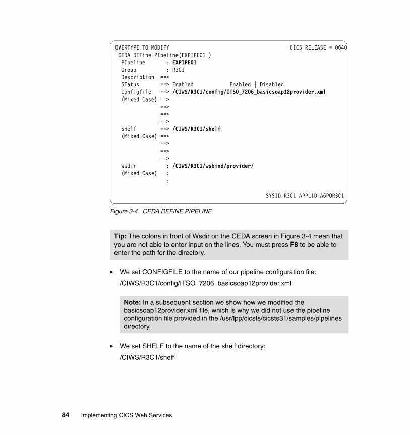
Figure 3-4 CEDA DEFINE PIPELINE
� We set CONFIGFILE to the name of our pipeline configuration file:
/CIWS/R3C1/config/ITSO_7206_basicsoap12provider.xml
� We set SHELF to the name of the shelf directory:
/CIWS/R3C1/shelf
Tip: The colons in front of Wsdir on the CEDA screen in Figure 3-4 mean that you are not able to enter input on the lines. You must press F8 to be able to enter the path for the directory.
Note: In a subsequent section we show how we modified the basicsoap12provider.xml file, which is why we did not use the pipeline configuration file provided in the /usr/lpp/cicsts/cicsts31/samples/pipelines directory.
OVERTYPE TO MODIFY CICS RELEASE = 0640 CEDA DEFine PIpeline(EXPIPE01 ) PIpeline : EXPIPE01 Group : R3C1 Description ==> STatus ==> Enabled Enabled | Disabled Configfile ==> /CIWS/R3C1/config/ITSO_7206_basicsoap12provider.xml (Mixed Case) ==> ==> ==> ==> SHelf ==> /CIWS/R3C1/shelf (Mixed Case) ==> ==> ==> ==> Wsdir : /CIWS/R3C1/wsbind/provider/ (Mixed Case) : : SYSID=R3C1 APPLID=A6POR3C1
84 Implementing CICS Web Services
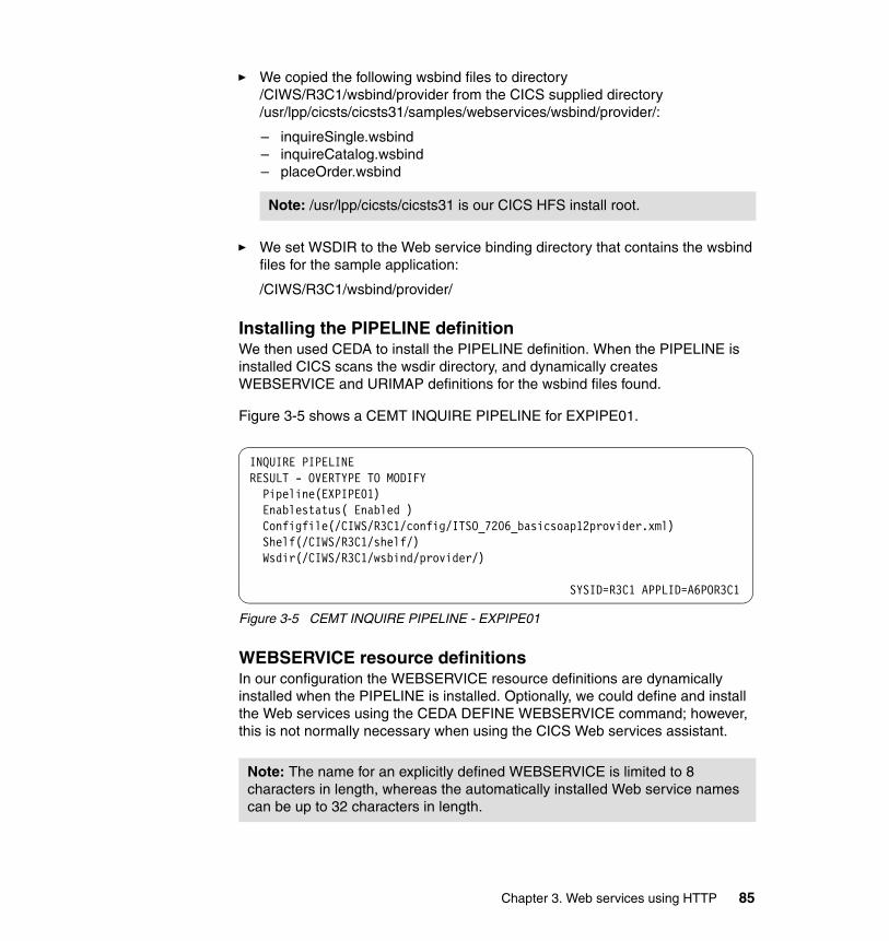
� We copied the following wsbind files to directory /CIWS/R3C1/wsbind/provider from the CICS supplied directory /usr/lpp/cicsts/cicsts31/samples/webservices/wsbind/provider/:
– inquireSingle.wsbind– inquireCatalog.wsbind– placeOrder.wsbind
� We set WSDIR to the Web service binding directory that contains the wsbind files for the sample application:
/CIWS/R3C1/wsbind/provider/
Installing the PIPELINE definitionWe then used CEDA to install the PIPELINE definition. When the PIPELINE is installed CICS scans the wsdir directory, and dynamically creates WEBSERVICE and URIMAP definitions for the wsbind files found.
Figure 3-5 shows a CEMT INQUIRE PIPELINE for EXPIPE01.
Figure 3-5 CEMT INQUIRE PIPELINE - EXPIPE01
WEBSERVICE resource definitionsIn our configuration the WEBSERVICE resource definitions are dynamically installed when the PIPELINE is installed. Optionally, we could define and install the Web services using the CEDA DEFINE WEBSERVICE command; however, this is not normally necessary when using the CICS Web services assistant.
Note: /usr/lpp/cicsts/cicsts31 is our CICS HFS install root.
Note: The name for an explicitly defined WEBSERVICE is limited to 8 characters in length, whereas the automatically installed Web service names can be up to 32 characters in length.
INQUIRE PIPELINE RESULT - OVERTYPE TO MODIFY Pipeline(EXPIPE01) Enablestatus( Enabled ) Configfile(/CIWS/R3C1/config/ITSO_7206_basicsoap12provider.xml) Shelf(/CIWS/R3C1/shelf/) Wsdir(/CIWS/R3C1/wsbind/provider/)
SYSID=R3C1 APPLID=A6POR3C1
Chapter 3. Web services using HTTP 85
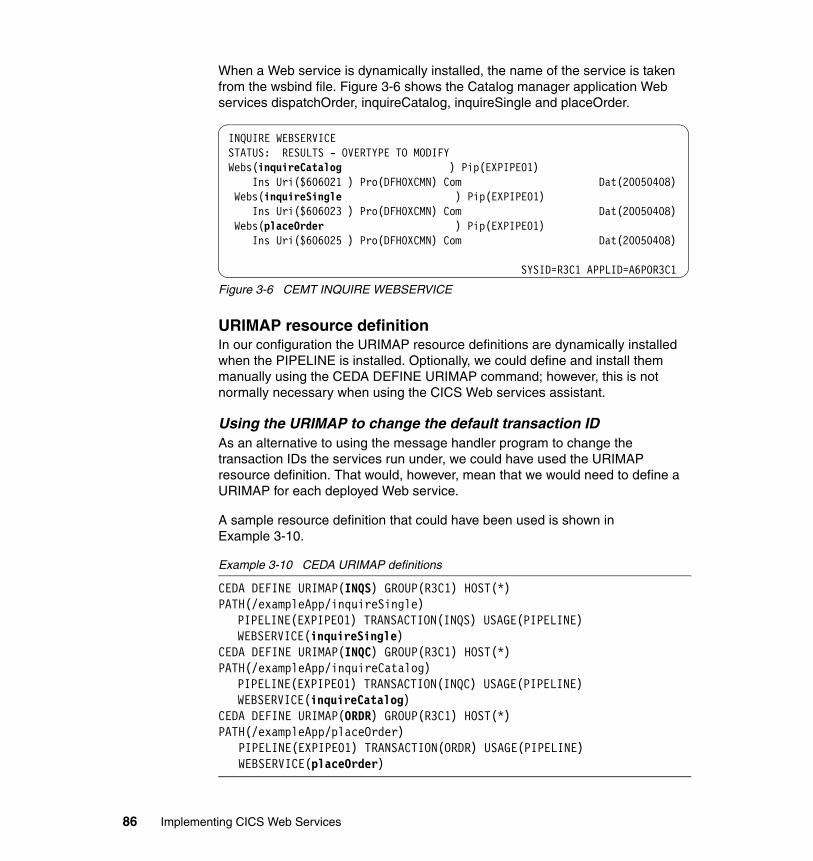
When a Web service is dynamically installed, the name of the service is taken from the wsbind file. Figure 3-6 shows the Catalog manager application Web services dispatchOrder, inquireCatalog, inquireSingle and placeOrder.
Figure 3-6 CEMT INQUIRE WEBSERVICE
URIMAP resource definitionIn our configuration the URIMAP resource definitions are dynamically installed when the PIPELINE is installed. Optionally, we could define and install them manually using the CEDA DEFINE URIMAP command; however, this is not normally necessary when using the CICS Web services assistant.
Using the URIMAP to change the default transaction IDAs an alternative to using the message handler program to change the transaction IDs the services run under, we could have used the URIMAP resource definition. That would, however, mean that we would need to define a URIMAP for each deployed Web service.
A sample resource definition that could have been used is shown in Example 3-10.
Example 3-10 CEDA URIMAP definitions
CEDA DEFINE URIMAP(INQS) GROUP(R3C1) HOST(*) PATH(/exampleApp/inquireSingle)
PIPELINE(EXPIPE01) TRANSACTION(INQS) USAGE(PIPELINE) WEBSERVICE(inquireSingle)
CEDA DEFINE URIMAP(INQC) GROUP(R3C1) HOST(*) PATH(/exampleApp/inquireCatalog)
PIPELINE(EXPIPE01) TRANSACTION(INQC) USAGE(PIPELINE) WEBSERVICE(inquireCatalog)
CEDA DEFINE URIMAP(ORDR) GROUP(R3C1) HOST(*) PATH(/exampleApp/placeOrder)
PIPELINE(EXPIPE01) TRANSACTION(ORDR) USAGE(PIPELINE)WEBSERVICE(placeOrder)
INQUIRE WEBSERVICE STATUS: RESULTS - OVERTYPE TO MODIFY Webs(inquireCatalog ) Pip(EXPIPE01) Ins Uri($606021 ) Pro(DFH0XCMN) Com Dat(20050408) Webs(inquireSingle ) Pip(EXPIPE01) Ins Uri($606023 ) Pro(DFH0XCMN) Com Dat(20050408) Webs(placeOrder ) Pip(EXPIPE01) Ins Uri($606025 ) Pro(DFH0XCMN) Com Dat(20050408) SYSID=R3C1 APPLID=A6POR3C1
86 Implementing CICS Web Services
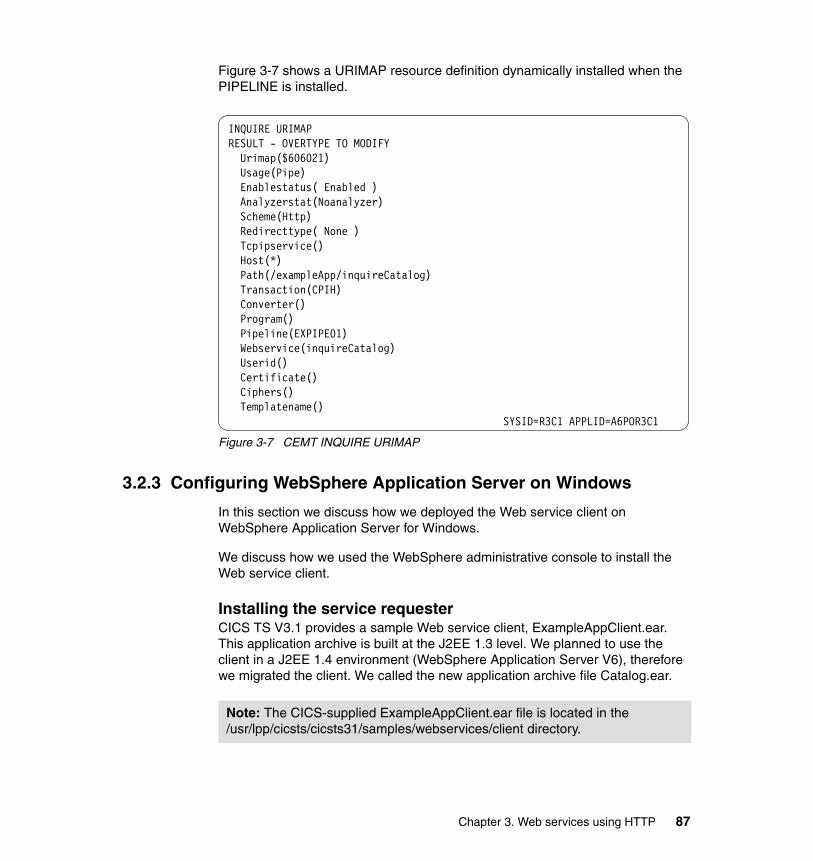
Figure 3-7 shows a URIMAP resource definition dynamically installed when the PIPELINE is installed.
Figure 3-7 CEMT INQUIRE URIMAP
3.2.3 Configuring WebSphere Application Server on Windows
In this section we discuss how we deployed the Web service client on WebSphere Application Server for Windows.
We discuss how we used the WebSphere administrative console to install the Web service client.
Installing the service requesterCICS TS V3.1 provides a sample Web service client, ExampleAppClient.ear. This application archive is built at the J2EE 1.3 level. We planned to use the client in a J2EE 1.4 environment (WebSphere Application Server V6), therefore we migrated the client. We called the new application archive file Catalog.ear.
INQUIRE URIMAP RESULT - OVERTYPE TO MODIFY Urimap($606021) Usage(Pipe) Enablestatus( Enabled ) Analyzerstat(Noanalyzer) Scheme(Http) Redirecttype( None ) Tcpipservice() Host(*) Path(/exampleApp/inquireCatalog) Transaction(CPIH) Converter() Program() Pipeline(EXPIPE01) Webservice(inquireCatalog) Userid() Certificate() Ciphers() Templatename() SYSID=R3C1 APPLID=A6POR3C1
Note: The CICS-supplied ExampleAppClient.ear file is located in the /usr/lpp/cicsts/cicsts31/samples/webservices/client directory.
Chapter 3. Web services using HTTP 87
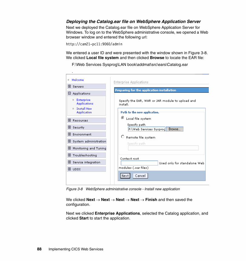
Deploying the Catalog.ear file on WebSphere Application Server Next we deployed the Catalog.ear file on WebSphere Application Server for Windows. To log on to the WebSphere administrative console, we opened a Web browser window and entered the following url:
http://cam21-pc11:9060/admin
We entered a user ID and were presented with the window shown in Figure 3-8. We clicked Local file system and then clicked Browse to locate the EAR file:
F:\Web Services Sysprog\LAN book\addmat\src\ears\Catalog.ear
.
Figure 3-8 WebSphere administrative console - Install new application
We clicked Next → Next → Next → Next → Finish and then saved the configuration.
Next we clicked Enterprise Applications, selected the Catalog application, and clicked Start to start the application.
88 Implementing CICS Web Services
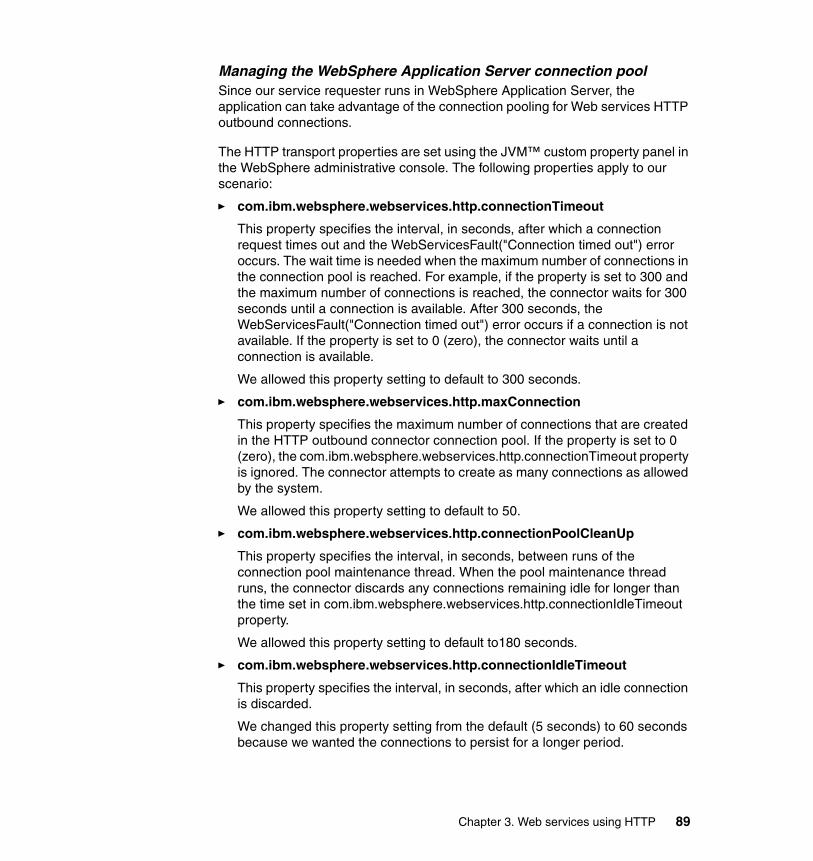
Managing the WebSphere Application Server connection poolSince our service requester runs in WebSphere Application Server, the application can take advantage of the connection pooling for Web services HTTP outbound connections.
The HTTP transport properties are set using the JVM™ custom property panel in the WebSphere administrative console. The following properties apply to our scenario:
� com.ibm.websphere.webservices.http.connectionTimeout
This property specifies the interval, in seconds, after which a connection request times out and the WebServicesFault("Connection timed out") error occurs. The wait time is needed when the maximum number of connections in the connection pool is reached. For example, if the property is set to 300 and the maximum number of connections is reached, the connector waits for 300 seconds until a connection is available. After 300 seconds, the WebServicesFault("Connection timed out") error occurs if a connection is not available. If the property is set to 0 (zero), the connector waits until a connection is available.
We allowed this property setting to default to 300 seconds.
� com.ibm.websphere.webservices.http.maxConnection
This property specifies the maximum number of connections that are created in the HTTP outbound connector connection pool. If the property is set to 0 (zero), the com.ibm.websphere.webservices.http.connectionTimeout property is ignored. The connector attempts to create as many connections as allowed by the system.
We allowed this property setting to default to 50.
� com.ibm.websphere.webservices.http.connectionPoolCleanUp
This property specifies the interval, in seconds, between runs of the connection pool maintenance thread. When the pool maintenance thread runs, the connector discards any connections remaining idle for longer than the time set in com.ibm.websphere.webservices.http.connectionIdleTimeout property.
We allowed this property setting to default to180 seconds.
� com.ibm.websphere.webservices.http.connectionIdleTimeout
This property specifies the interval, in seconds, after which an idle connection is discarded.
We changed this property setting from the default (5 seconds) to 60 seconds because we wanted the connections to persist for a longer period.
Chapter 3. Web services using HTTP 89
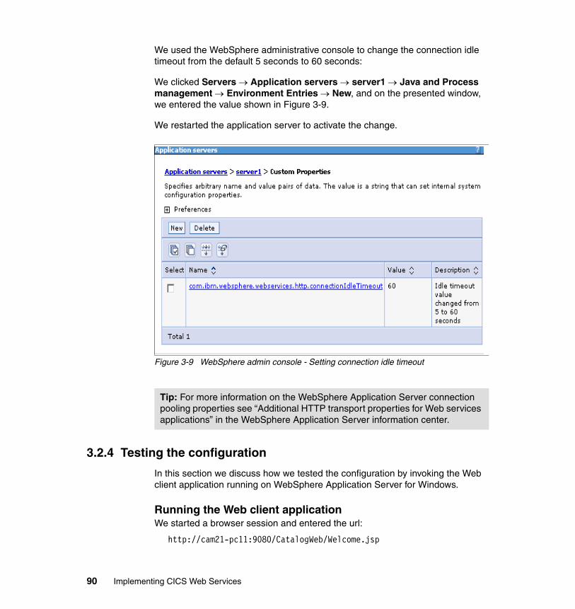
We used the WebSphere administrative console to change the connection idle timeout from the default 5 seconds to 60 seconds:
We clicked Servers → Application servers → server1 → Java and Process management → Environment Entries → New, and on the presented window, we entered the value shown in Figure 3-9.
We restarted the application server to activate the change.
Figure 3-9 WebSphere admin console - Setting connection idle timeout
3.2.4 Testing the configuration
In this section we discuss how we tested the configuration by invoking the Web client application running on WebSphere Application Server for Windows.
Running the Web client applicationWe started a browser session and entered the url:
http://cam21-pc11:9080/CatalogWeb/Welcome.jsp
Tip: For more information on the WebSphere Application Server connection pooling properties see “Additional HTTP transport properties for Web services applications” in the WebSphere Application Server information center.
90 Implementing CICS Web Services
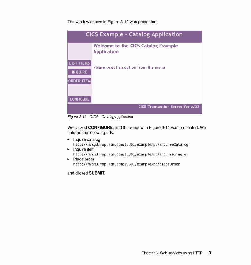
The window shown in Figure 3-10 was presented.
Figure 3-10 CICS - Catalog application
We clicked CONFIGURE, and the window in Figure 3-11 was presented. We entered the following urls:
� Inquire cataloghttp://mvsg3.mop.ibm.com:13301/exampleApp/inquireCatalog
� Inquire itemhttp://mvsg3.mop.ibm.com:13301/exampleApp/inquireSingle
� Place orderhttp://mvsg3.mop.ibm.com:13301/exampleApp/placeOrder
and clicked SUBMIT.
Chapter 3. Web services using HTTP 91
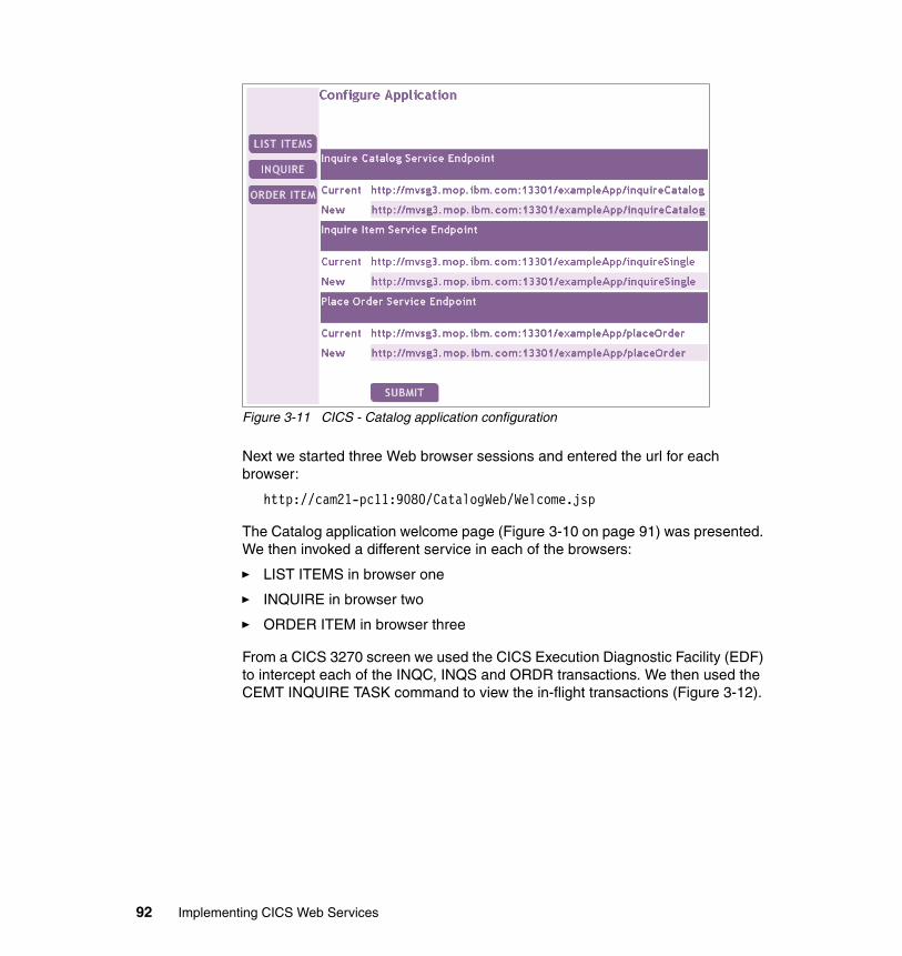
Figure 3-11 CICS - Catalog application configuration
Next we started three Web browser sessions and entered the url for each browser:
http://cam21-pc11:9080/CatalogWeb/Welcome.jsp
The Catalog application welcome page (Figure 3-10 on page 91) was presented. We then invoked a different service in each of the browsers:
� LIST ITEMS in browser one
� INQUIRE in browser two
� ORDER ITEM in browser three
From a CICS 3270 screen we used the CICS Execution Diagnostic Facility (EDF) to intercept each of the INQC, INQS and ORDR transactions. We then used the CEMT INQUIRE TASK command to view the in-flight transactions (Figure 3-12).
92 Implementing CICS Web Services
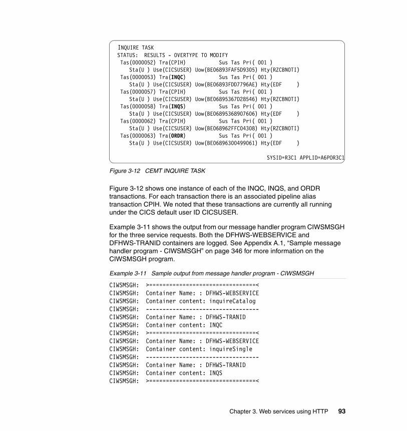
Figure 3-12 CEMT INQUIRE TASK
Figure 3-12 shows one instance of each of the INQC, INQS, and ORDR transactions. For each transaction there is an associated pipeline alias transaction CPIH. We noted that these transactions are currently all running under the CICS default user ID CICSUSER.
Example 3-11 shows the output from our message handler program CIWSMSGH for the three service requests. Both the DFHWS-WEBSERVICE and DFHWS-TRANID containers are logged. See Appendix A.1, “Sample message handler program - CIWSMSGH” on page 346 for more information on the CIWSMSGH program.
Example 3-11 Sample output from message handler program - CIWSMSGH
CIWSMSGH: >================================< CIWSMSGH: Container Name: : DFHWS-WEBSERVICE CIWSMSGH: Container content: inquireCatalog CIWSMSGH: ---------------------------------- CIWSMSGH: Container Name: : DFHWS-TRANID CIWSMSGH: Container content: INQC CIWSMSGH: >================================< CIWSMSGH: Container Name: : DFHWS-WEBSERVICE CIWSMSGH: Container content: inquireSingle CIWSMSGH: ---------------------------------- CIWSMSGH: Container Name: : DFHWS-TRANID CIWSMSGH: Container content: INQS CIWSMSGH: >================================<
INQUIRE TASK STATUS: RESULTS - OVERTYPE TO MODIFY Tas(0000052) Tra(CPIH) Sus Tas Pri( 001 )
Sta(U ) Use(CICSUSER) Uow(BE06893FAF5D9305) Hty(RZCBNOTI) Tas(0000053) Tra(INQC) Sus Tas Pri( 001 ) Sta(U ) Use(CICSUSER) Uow(BE06893FDD7796AE) Hty(EDF ) Tas(0000057) Tra(CPIH) Sus Tas Pri( 001 )
Sta(U ) Use(CICSUSER) Uow(BE06895367D28546) Hty(RZCBNOTI) Tas(0000058) Tra(INQS) Sus Tas Pri( 001 ) Sta(U ) Use(CICSUSER) Uow(BE06895368907606) Hty(EDF ) Tas(0000062) Tra(CPIH) Sus Tas Pri( 001 )
Sta(U ) Use(CICSUSER) Uow(BE068962FFC04308) Hty(RZCBNOTI) Tas(0000063) Tra(ORDR) Sus Tas Pri( 001 )
Sta(U ) Use(CICSUSER) Uow(BE06896300499061) Hty(EDF )
SYSID=R3C1 APPLID=A6POR3C1
Chapter 3. Web services using HTTP 93
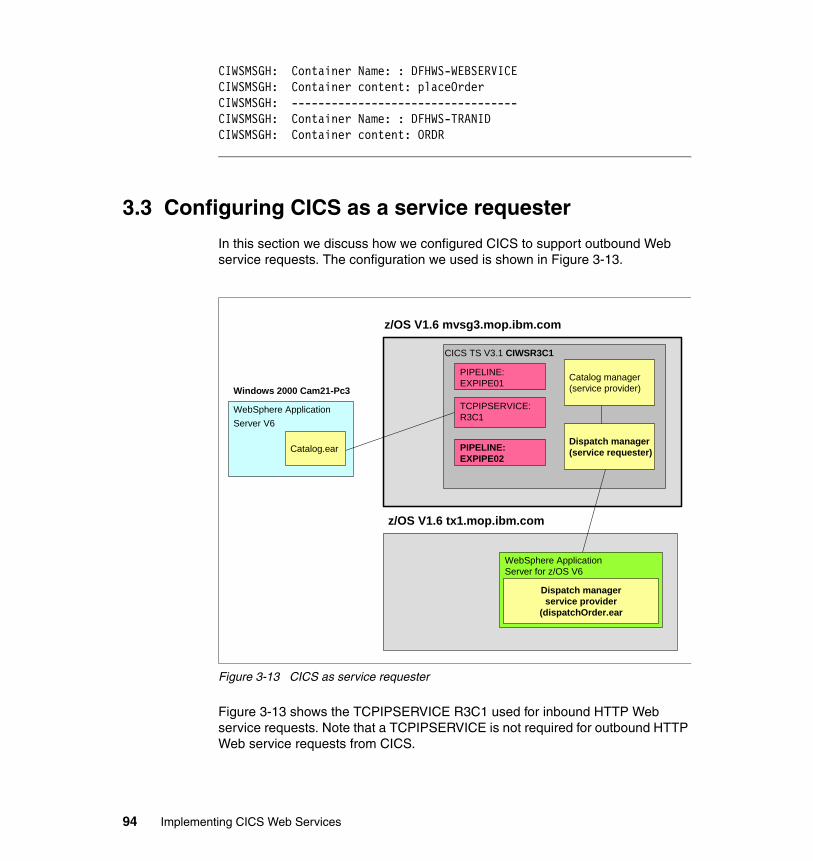
CIWSMSGH: Container Name: : DFHWS-WEBSERVICE CIWSMSGH: Container content: placeOrder CIWSMSGH: ---------------------------------- CIWSMSGH: Container Name: : DFHWS-TRANID CIWSMSGH: Container content: ORDR
3.3 Configuring CICS as a service requester
In this section we discuss how we configured CICS to support outbound Web service requests. The configuration we used is shown in Figure 3-13.
Figure 3-13 CICS as service requester
Figure 3-13 shows the TCPIPSERVICE R3C1 used for inbound HTTP Web service requests. Note that a TCPIPSERVICE is not required for outbound HTTP Web service requests from CICS.
CICS TS V3.1 CIWSR3C1
WebSphere Application Server V6
Windows 2000 Cam21-Pc3
z/OS V1.6 mvsg3.mop.ibm.com
Catalog manager(service provider)
Catalog.ear
TCPIPSERVICE:R3C1
PIPELINE:EXPIPE01
Dispatch manager(service requester)PIPELINE:
EXPIPE02
z/OS V1.6 tx1.mop.ibm.com
WebSphere Application Server for z/OS V6
Dispatch managerservice provider
(dispatchOrder.ear
94 Implementing CICS Web Services
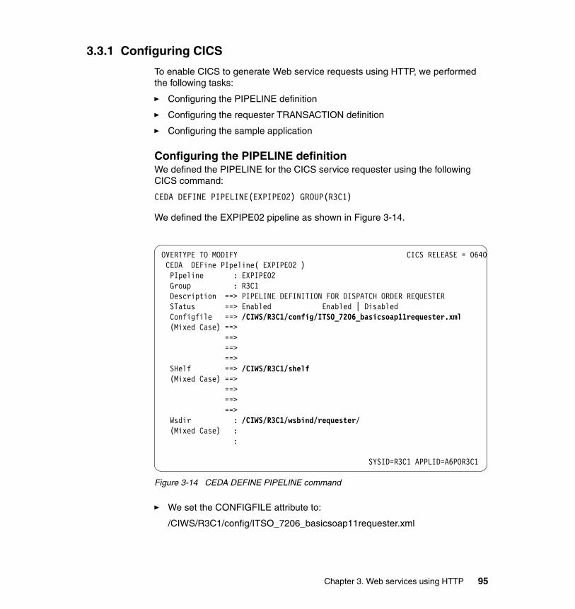
3.3.1 Configuring CICS
To enable CICS to generate Web service requests using HTTP, we performed the following tasks:
� Configuring the PIPELINE definition
� Configuring the requester TRANSACTION definition
� Configuring the sample application
Configuring the PIPELINE definitionWe defined the PIPELINE for the CICS service requester using the following CICS command:
CEDA DEFINE PIPELINE(EXPIPE02) GROUP(R3C1)
We defined the EXPIPE02 pipeline as shown in Figure 3-14.
Figure 3-14 CEDA DEFINE PIPELINE command
� We set the CONFIGFILE attribute to:
/CIWS/R3C1/config/ITSO_7206_basicsoap11requester.xml
OVERTYPE TO MODIFY CICS RELEASE = 0640 CEDA DEFine PIpeline( EXPIPE02 ) PIpeline : EXPIPE02 Group : R3C1 Description ==> PIPELINE DEFINITION FOR DISPATCH ORDER REQUESTER STatus ==> Enabled Enabled | Disabled Configfile ==> /CIWS/R3C1/config/ITSO_7206_basicsoap11requester.xml (Mixed Case) ==> ==> ==> ==> SHelf ==> /CIWS/R3C1/shelf (Mixed Case) ==> ==> ==> ==> Wsdir : /CIWS/R3C1/wsbind/requester/ (Mixed Case) : :
SYSID=R3C1 APPLID=A6POR3C1
Chapter 3. Web services using HTTP 95
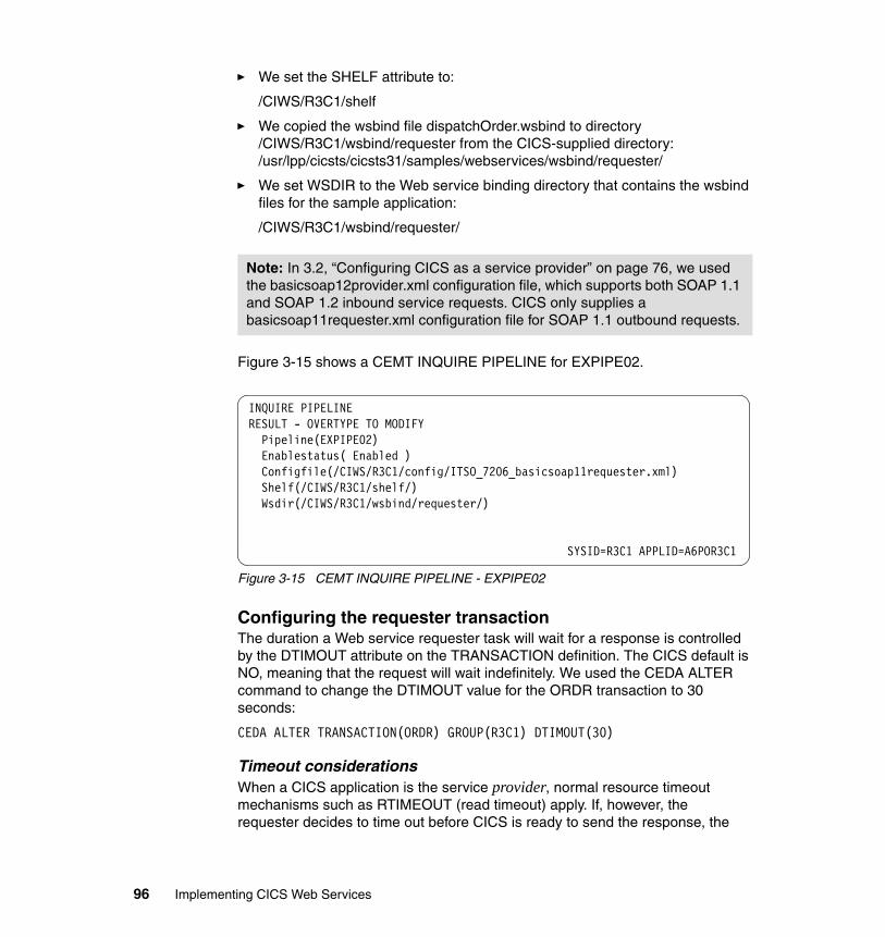
� We set the SHELF attribute to:
/CIWS/R3C1/shelf
� We copied the wsbind file dispatchOrder.wsbind to directory /CIWS/R3C1/wsbind/requester from the CICS-supplied directory:/usr/lpp/cicsts/cicsts31/samples/webservices/wsbind/requester/
� We set WSDIR to the Web service binding directory that contains the wsbind files for the sample application:
/CIWS/R3C1/wsbind/requester/
Figure 3-15 shows a CEMT INQUIRE PIPELINE for EXPIPE02.
Figure 3-15 CEMT INQUIRE PIPELINE - EXPIPE02
Configuring the requester transactionThe duration a Web service requester task will wait for a response is controlled by the DTIMOUT attribute on the TRANSACTION definition. The CICS default is NO, meaning that the request will wait indefinitely. We used the CEDA ALTER command to change the DTIMOUT value for the ORDR transaction to 30 seconds:
CEDA ALTER TRANSACTION(ORDR) GROUP(R3C1) DTIMOUT(30)
Timeout considerationsWhen a CICS application is the service provider, normal resource timeout mechanisms such as RTIMEOUT (read timeout) apply. If, however, the requester decides to time out before CICS is ready to send the response, the
Note: In 3.2, “Configuring CICS as a service provider” on page 76, we used the basicsoap12provider.xml configuration file, which supports both SOAP 1.1 and SOAP 1.2 inbound service requests. CICS only supplies a basicsoap11requester.xml configuration file for SOAP 1.1 outbound requests.
INQUIRE PIPELINE RESULT - OVERTYPE TO MODIFY Pipeline(EXPIPE02) Enablestatus( Enabled ) Configfile(/CIWS/R3C1/config/ITSO_7206_basicsoap11requester.xml) Shelf(/CIWS/R3C1/shelf/) Wsdir(/CIWS/R3C1/wsbind/requester/)
SYSID=R3C1 APPLID=A6POR3C1
96 Implementing CICS Web Services
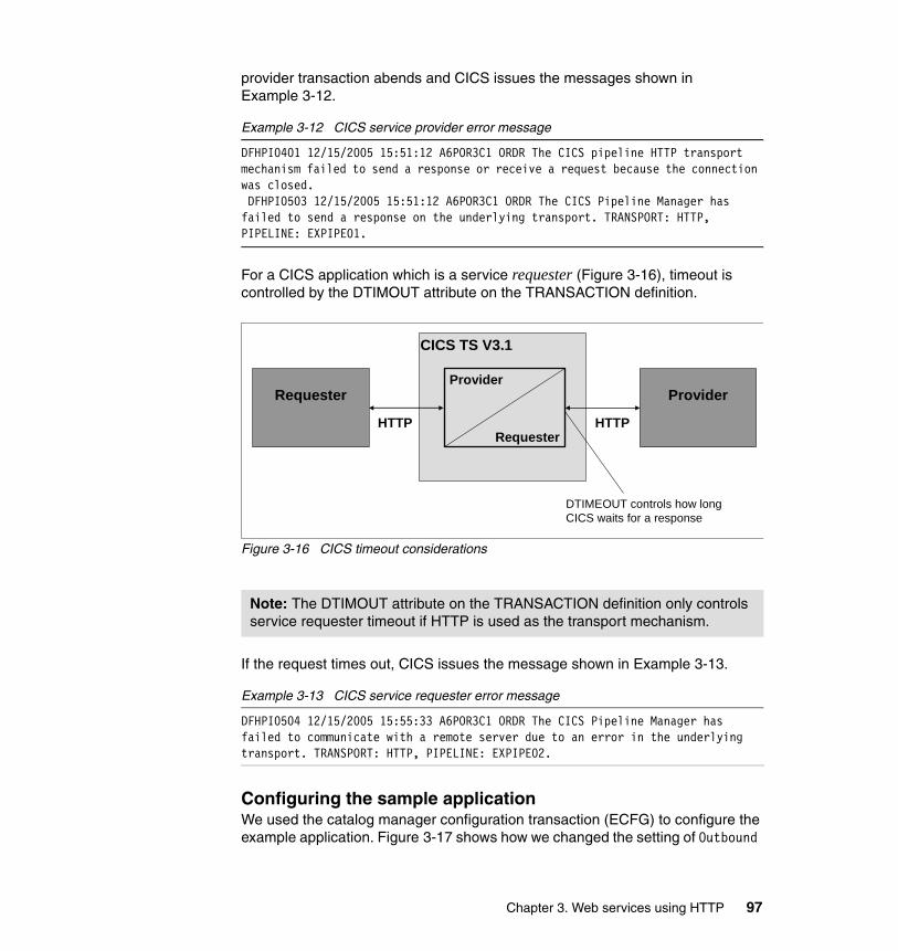
provider transaction abends and CICS issues the messages shown in Example 3-12.
Example 3-12 CICS service provider error message
DFHPI0401 12/15/2005 15:51:12 A6POR3C1 ORDR The CICS pipeline HTTP transport mechanism failed to send a response or receive a request because the connection was closed. DFHPI0503 12/15/2005 15:51:12 A6POR3C1 ORDR The CICS Pipeline Manager has failed to send a response on the underlying transport. TRANSPORT: HTTP, PIPELINE: EXPIPE01.
For a CICS application which is a service requester (Figure 3-16), timeout is controlled by the DTIMOUT attribute on the TRANSACTION definition.
Figure 3-16 CICS timeout considerations
If the request times out, CICS issues the message shown in Example 3-13.
Example 3-13 CICS service requester error message
DFHPI0504 12/15/2005 15:55:33 A6POR3C1 ORDR The CICS Pipeline Manager has failed to communicate with a remote server due to an error in the underlying transport. TRANSPORT: HTTP, PIPELINE: EXPIPE02.
Configuring the sample applicationWe used the catalog manager configuration transaction (ECFG) to configure the example application. Figure 3-17 shows how we changed the setting of Outbound
Note: The DTIMOUT attribute on the TRANSACTION definition only controls service requester timeout if HTTP is used as the transport mechanism.
Requester Provider
CICS TS V3.1
Provider
RequesterHTTP HTTP
DTIMEOUT controls how longCICS waits for a response
Chapter 3. Web services using HTTP 97
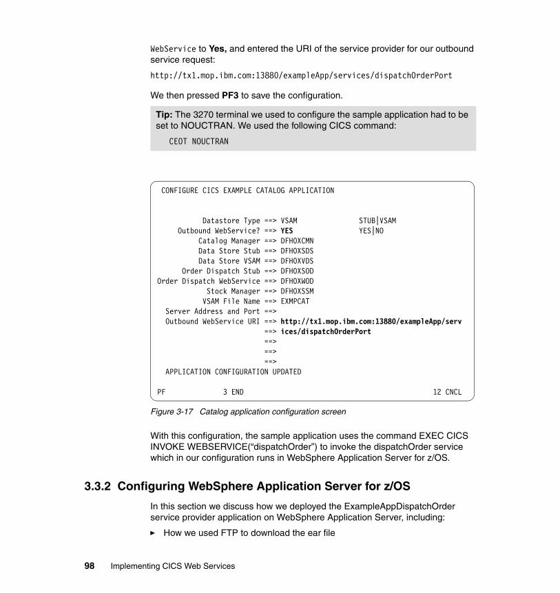
WebService to Yes, and entered the URI of the service provider for our outbound service request:
http://tx1.mop.ibm.com:13880/exampleApp/services/dispatchOrderPort
We then pressed PF3 to save the configuration.
Figure 3-17 Catalog application configuration screen
With this configuration, the sample application uses the command EXEC CICS INVOKE WEBSERVICE(“dispatchOrder”) to invoke the dispatchOrder service which in our configuration runs in WebSphere Application Server for z/OS.
3.3.2 Configuring WebSphere Application Server for z/OS
In this section we discuss how we deployed the ExampleAppDispatchOrder service provider application on WebSphere Application Server, including:
� How we used FTP to download the ear file
Tip: The 3270 terminal we used to configure the sample application had to be set to NOUCTRAN. We used the following CICS command:
CEOT NOUCTRAN
CONFIGURE CICS EXAMPLE CATALOG APPLICATION Datastore Type ==> VSAM STUB|VSAM Outbound WebService? ==> YES YES|NO Catalog Manager ==> DFH0XCMN Data Store Stub ==> DFH0XSDS Data Store VSAM ==> DFH0XVDS Order Dispatch Stub ==> DFH0XSOD Order Dispatch WebService ==> DFH0XWOD Stock Manager ==> DFH0XSSM VSAM File Name ==> EXMPCAT Server Address and Port ==> Outbound WebService URI ==> http://tx1.mop.ibm.com:13880/exampleApp/serv ==> ices/dispatchOrderPort ==> ==> ==> APPLICATION CONFIGURATION UPDATED PF 3 END 12 CNCL
98 Implementing CICS Web Services
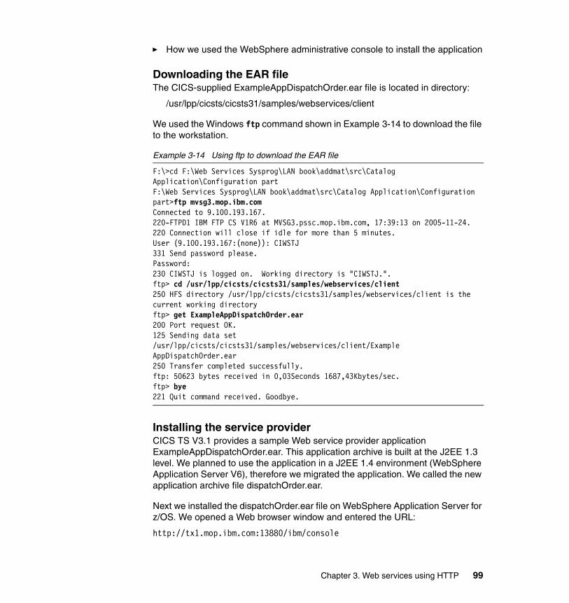
� How we used the WebSphere administrative console to install the application
Downloading the EAR fileThe CICS-supplied ExampleAppDispatchOrder.ear file is located in directory:
/usr/lpp/cicsts/cicsts31/samples/webservices/client
We used the Windows ftp command shown in Example 3-14 to download the file to the workstation.
Example 3-14 Using ftp to download the EAR file
F:\>cd F:\Web Services Sysprog\LAN book\addmat\src\Catalog Application\Configuration partF:\Web Services Sysprog\LAN book\addmat\src\Catalog Application\Configuration part>ftp mvsg3.mop.ibm.comConnected to 9.100.193.167.220-FTPD1 IBM FTP CS V1R6 at MVSG3.pssc.mop.ibm.com, 17:39:13 on 2005-11-24.220 Connection will close if idle for more than 5 minutes.User (9.100.193.167:(none)): CIWSTJ331 Send password please.Password:230 CIWSTJ is logged on. Working directory is "CIWSTJ.".ftp> cd /usr/lpp/cicsts/cicsts31/samples/webservices/client250 HFS directory /usr/lpp/cicsts/cicsts31/samples/webservices/client is the current working directoryftp> get ExampleAppDispatchOrder.ear200 Port request OK.125 Sending data set /usr/lpp/cicsts/cicsts31/samples/webservices/client/ExampleAppDispatchOrder.ear250 Transfer completed successfully.ftp: 50623 bytes received in 0,03Seconds 1687,43Kbytes/sec.ftp> bye221 Quit command received. Goodbye.
Installing the service providerCICS TS V3.1 provides a sample Web service provider application ExampleAppDispatchOrder.ear. This application archive is built at the J2EE 1.3 level. We planned to use the application in a J2EE 1.4 environment (WebSphere Application Server V6), therefore we migrated the application. We called the new application archive file dispatchOrder.ear.
Next we installed the dispatchOrder.ear file on WebSphere Application Server for z/OS. We opened a Web browser window and entered the URL:
http://tx1.mop.ibm.com:13880/ibm/console
Chapter 3. Web services using HTTP 99
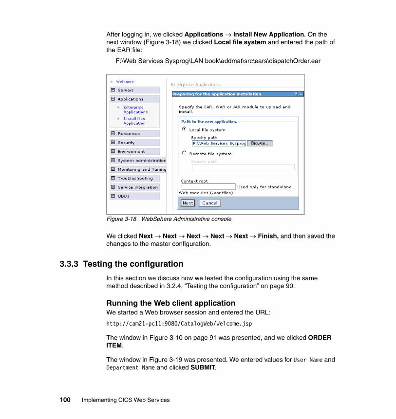
After logging in, we clicked Applications → Install New Application. On the next window (Figure 3-18) we clicked Local file system and entered the path of the EAR file:
F:\Web Services Sysprog\LAN book\addmat\src\ears\dispatchOrder.ear
Figure 3-18 WebSphere Administrative console
We clicked Next → Next → Next → Next → Next → Finish, and then saved the changes to the master configuration.
3.3.3 Testing the configuration
In this section we discuss how we tested the configuration using the same method described in 3.2.4, “Testing the configuration” on page 90.
Running the Web client applicationWe started a Web browser session and entered the URL:
http://cam21-pc11:9080/CatalogWeb/Welcome.jsp
The window in Figure 3-10 on page 91 was presented, and we clicked ORDER ITEM.
The window in Figure 3-19 was presented. We entered values for User Name and Department Name and clicked SUBMIT.
100 Implementing CICS Web Services
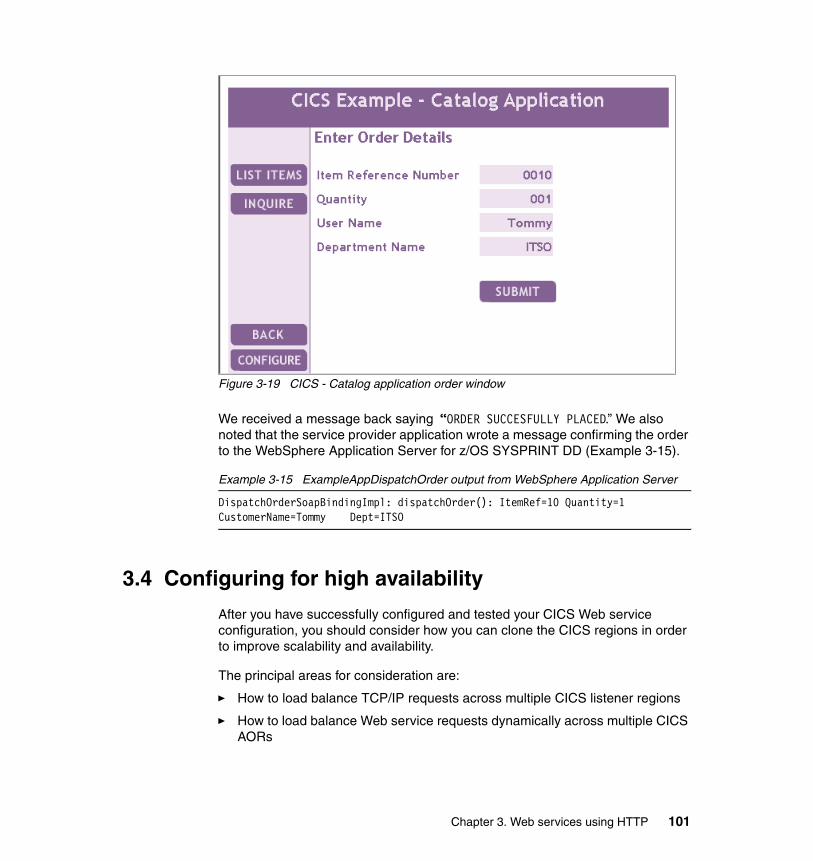
Figure 3-19 CICS - Catalog application order window
We received a message back saying “ORDER SUCCESFULLY PLACED.” We also noted that the service provider application wrote a message confirming the order to the WebSphere Application Server for z/OS SYSPRINT DD (Example 3-15).
Example 3-15 ExampleAppDispatchOrder output from WebSphere Application Server
DispatchOrderSoapBindingImpl: dispatchOrder(): ItemRef=10 Quantity=1 CustomerName=Tommy Dept=ITSO
3.4 Configuring for high availability
After you have successfully configured and tested your CICS Web service configuration, you should consider how you can clone the CICS regions in order to improve scalability and availability.
The principal areas for consideration are:
� How to load balance TCP/IP requests across multiple CICS listener regions
� How to load balance Web service requests dynamically across multiple CICS AORs
Chapter 3. Web services using HTTP 101
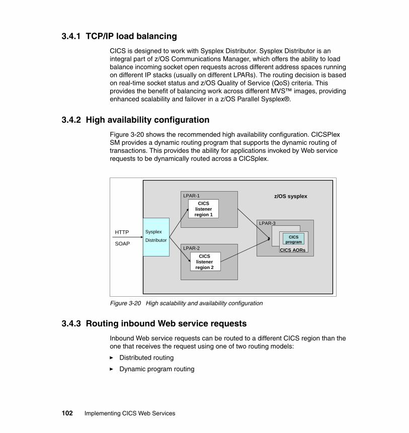
3.4.1 TCP/IP load balancing
CICS is designed to work with Sysplex Distributor. Sysplex Distributor is an integral part of z/OS Communications Manager, which offers the ability to load balance incoming socket open requests across different address spaces running on different IP stacks (usually on different LPARs). The routing decision is based on real-time socket status and z/OS Quality of Service (QoS) criteria. This provides the benefit of balancing work across different MVS™ images, providing enhanced scalability and failover in a z/OS Parallel Sysplex®.
3.4.2 High availability configuration
Figure 3-20 shows the recommended high availability configuration. CICSPlex SM provides a dynamic routing program that supports the dynamic routing of transactions. This provides the ability for applications invoked by Web service requests to be dynamically routed across a CICSplex.
Figure 3-20 High scalability and availability configuration
3.4.3 Routing inbound Web service requests
Inbound Web service requests can be routed to a different CICS region than the one that receives the request using one of two routing models:
� Distributed routing
� Dynamic program routing
HTTP Sysplex
Distributor
LPAR-1
LPAR-2
LPAR-3
CICSlistenerregion 1
CICSlistenerregion 2
CICS AORs
z/OS sysplex
CICSprogramSOAP
102 Implementing CICS Web Services
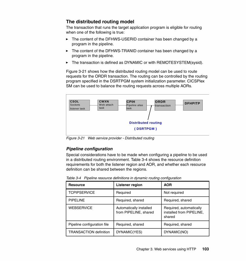
The distributed routing modelThe transaction that runs the target application program is eligible for routing when one of the following is true:
� The content of the DFHWS-USERID container has been changed by a program in the pipeline.
� The content of the DFHWS-TRANID container has been changed by a program in the pipeline.
� The transaction is defined as DYNAMIC or with REMOTESYSTEM(sysid).
Figure 3-21 shows how the distributed routing model can be used to route requests for the ORDR transaction. The routing can be controlled by the routing program specified in the DSRTPGM system initialization parameter. CICSPlex SM can be used to balance the routing requests across multiple AORs.
Figure 3-21 Web service provider - Distributed routing
Pipeline configurationSpecial considerations have to be made when configuring a pipeline to be used in a distributed routing environment. Table 3-4 shows the resource definition requirements for both the listener region and AOR, and whether each resource definition can be shared between the regions.
Table 3-4 Pipeline resource definitions in dynamic routing configuration
Resource Listener region AOR
TCPIPSERVICE Required Not required
PIPELINE Required, shared Required, shared
WEBSERVICE Automatically installed from PIPELINE, shared
Required, automatically installed from PIPELINE, shared
Pipeline configuration file Required, shared Required, shared
TRANSACTION definition DYNAMIC(YES) DYNAMIC(NO)
CSOLSocketslistener task
CWXNWeb attach task
CPIHPipeline alias task
ORDRtransaction
DFHPITP
Distributed routing
( DSRTPGM )
Chapter 3. Web services using HTTP 103
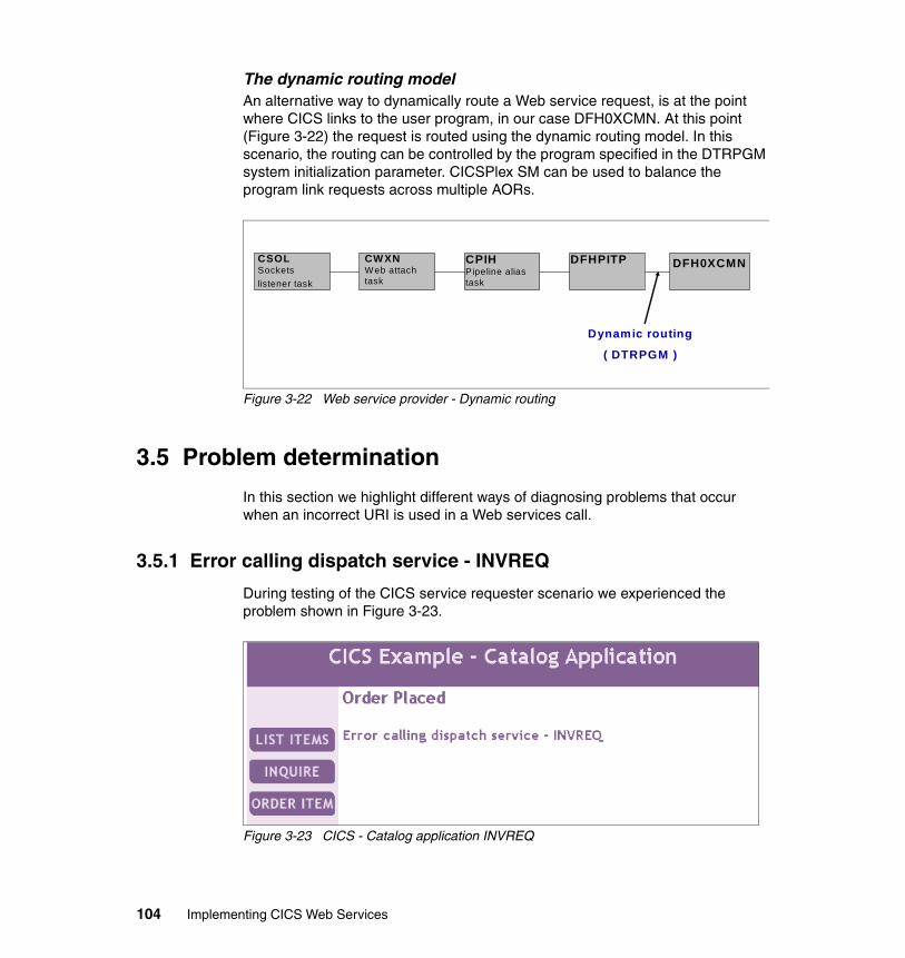
The dynamic routing modelAn alternative way to dynamically route a Web service request, is at the point where CICS links to the user program, in our case DFH0XCMN. At this point (Figure 3-22) the request is routed using the dynamic routing model. In this scenario, the routing can be controlled by the program specified in the DTRPGM system initialization parameter. CICSPlex SM can be used to balance the program link requests across multiple AORs.
Figure 3-22 Web service provider - Dynamic routing
3.5 Problem determination
In this section we highlight different ways of diagnosing problems that occur when an incorrect URI is used in a Web services call.
3.5.1 Error calling dispatch service - INVREQ
During testing of the CICS service requester scenario we experienced the problem shown in Figure 3-23.
Figure 3-23 CICS - Catalog application INVREQ
CSOLSocketslistener task
CWXNWeb attach task
CPIHPipeline alias task
DFHPITP
Dynamic routing
( DTRPGM )
DFH0XCMN
104 Implementing CICS Web Services
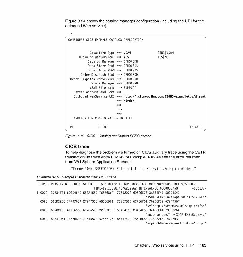
Figure 3-24 shows the catalog manager configuration (including the URI for the outbound Web service).
.
Figure 3-24 CICS - Catalog application ECFG screen
CICS traceTo help diagnose the problem we turned on CICS auxiliary trace using the CETR transaction. In trace entry 002142 of Example 3-16 we see the error returned from WebSphere Application Server:
“Error 404: SRVE0190E: File not found /services/dispatchOrder.”
Example 3-16 Sample DispatchOrder CICS trace
PI 0A31 PIIS EVENT - REQUEST_CNT - TASK-00182 KE_NUM-008C TCB-L8003/00ADC0A8 RET-9753E4F2 TIME-12:13:58.4376239562 INTERVAL-00.0000008750 =002137=
1-0000 3C534F41 502D454E 563A456E 76656C6F 70652078 6D6C6E73 3A534F41 502D454E *<SOAP-ENV:Envelope xmlns:SOAP-EN*
0020 563D2268 7474703A 2F2F7363 68656D61 732E786D 6C736F61 702E6F72 672F736F *V="http://schemas.xmlsoap.org/so*
0040 61702F65 6E76656C 6F70652F 22203E3C 534F4150 2D454E56 3A426F64 793E3C64 *ap/envelope/" ><SOAP-ENV:Body><d*
0060 69737061 7463684F 72646572 52657175 65737420 786D6C6E 733D2268 7474703A *ispatchOrderRequest xmlns="http:*
CONFIGURE CICS EXAMPLE CATALOG APPLICATION Datastore Type ==> VSAM STUB|VSAM Outbound WebService? ==> YES YES|NO Catalog Manager ==> DFH0XCMN Data Store Stub ==> DFH0XSDS Data Store VSAM ==> DFH0XVDS Order Dispatch Stub ==> DFH0XSOD Order Dispatch WebService ==> DFH0XWOD Stock Manager ==> DFH0XSSM VSAM File Name ==> EXMPCAT Server Address and Port ==> Outbound WebService URI ==> http://tx1.mop.ibm.com:13880/exampleApp/dispat ==> hOrder ==> ==> ==> APPLICATION CONFIGURATION UPDATED PF 3 END 12 CNCL
Chapter 3. Web services using HTTP 105
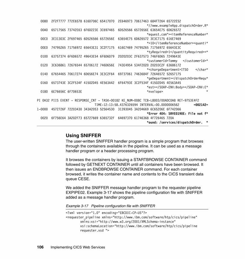
0080 2F2F7777 772E6578 616D706C 65417070 2E646973 70617463 684F7264 65722E52 *//www.exampleApp.dispatchOrder.R*
00A0 65717565 73742E63 6F6D223E 3C697465 6D526566 6572656E 63654E75 6D626572 *equest.com"><itemReferenceNumber*
00C0 3E31303C 2F697465 6D526566 6572656E 63654E75 6D626572 3E3C7175 616E7469 *>10</itemReferenceNumber><quanti*
00E0 74795265 71756972 65643E31 3C2F7175 616E7469 74795265 71756972 65643E3C *tyRequired>1</quantityRequired><*
0100 63757374 6F6D6572 49643E54 6F6D6D79 2020203C 2F637573 746F6D65 7249643E *customerId>Tommy </customerId>*
0120 3C636861 72676544 65706172 746D656E 743E4954 534F2020 20203C2F 63686172 *<chargeDepartment>ITSO </char*
0140 67654465 70617274 6D656E74 3E3C2F64 69737061 7463684F 72646572 52657175 *geDepartment></dispatchOrderRequ*
0160 6573743E 3C2F534F 41502D45 4E563A42 6F64793E 3C2F534F 41502D45 4E563A45 *est></SOAP-ENV:Body></SOAP-ENV:E*
0180 6E76656C 6F70653E *nvelope> *
PI 0A32 PIIS EVENT - RESPONSE_CNT - TASK-00182 KE_NUM-008C TCB-L8003/00ADC0A8 RET-9753E4F2 TIME-12:13:58.4376326594 INTERVAL-00.0000006562 =002142=
1-0000 4572726F 72203430 343A2053 52564530 31393045 3A204669 6C65206E 6F742066 *Error 404: SRVE0190E: File not f*
0020 6F756E64 3A202F73 65727669 6365732F 64697370 61746368 4F726465 720A *ound: /services/dispatchOrder. *
Using SNIFFERThe user-written SNIFFER handler program is a simple program that browses through the containers available in the pipeline. It can be used as a message handler program or a header processing program.
It browses the containers by issuing a STARTBROWSE CONTAINER command followed by GETNEXT CONTAINER until all containers have been browsed. It then issues an ENDBROWSE CONTAINER command. For each container browsed, it writes the container name and contents to the CICS transient data queue CESE.
We added the SNIFFER message handler program to the requester pipeline EXPIPE02. Example 3-17 shows the pipeline configuration file with SNIFFER added as a message handler program.
Example 3-17 Pipeline configuration file with SNIFFER
<?xml version="1.0" encoding="EBCDIC-CP-US"?><requester_pipeline xmlns="http://www.ibm.com/software/htp/cics/pipeline" xmlns:xsi="http://www.w3.org/2001/XMLSchema-instance"
xsi:schemaLocation="http://www.ibm.com/software/htp/cics/pipeline requester.xsd ">
106 Implementing CICS Web Services
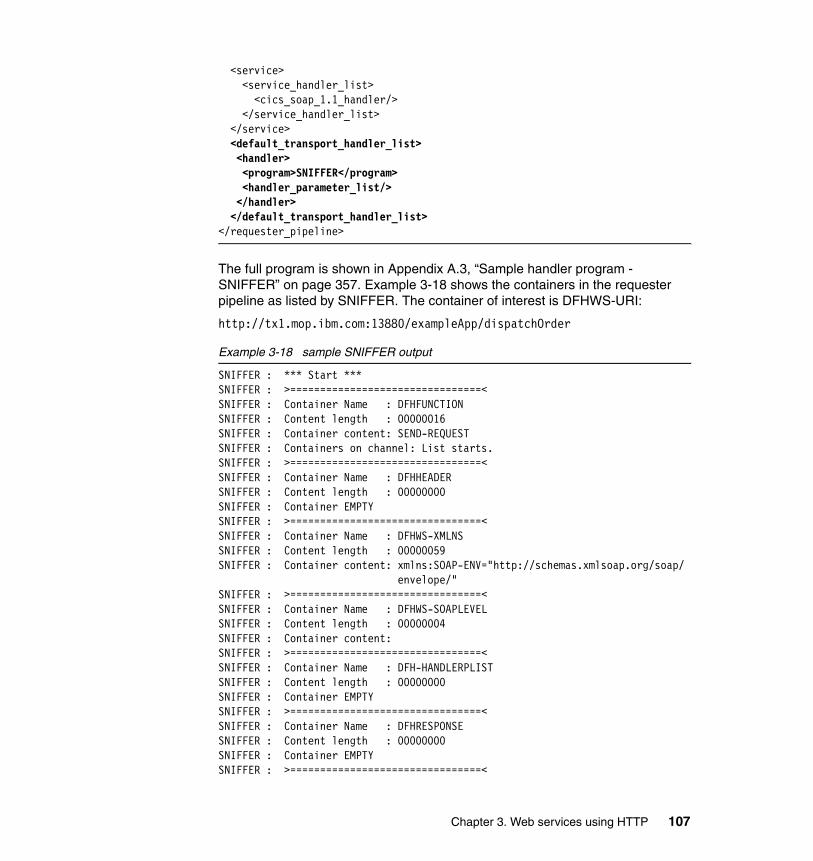
<service> <service_handler_list> <cics_soap_1.1_handler/> </service_handler_list> </service> <default_transport_handler_list> <handler> <program>SNIFFER</program> <handler_parameter_list/> </handler> </default_transport_handler_list></requester_pipeline>
The full program is shown in Appendix A.3, “Sample handler program - SNIFFER” on page 357. Example 3-18 shows the containers in the requester pipeline as listed by SNIFFER. The container of interest is DFHWS-URI:
http://tx1.mop.ibm.com:13880/exampleApp/dispatchOrder
Example 3-18 sample SNIFFER output
SNIFFER : *** Start ***SNIFFER : >================================<SNIFFER : Container Name : DFHFUNCTIONSNIFFER : Content length : 00000016SNIFFER : Container content: SEND-REQUESTSNIFFER : Containers on channel: List starts.SNIFFER : >================================<SNIFFER : Container Name : DFHHEADERSNIFFER : Content length : 00000000SNIFFER : Container EMPTYSNIFFER : >================================<SNIFFER : Container Name : DFHWS-XMLNSSNIFFER : Content length : 00000059SNIFFER : Container content: xmlns:SOAP-ENV="http://schemas.xmlsoap.org/soap/
envelope/"SNIFFER : >================================<SNIFFER : Container Name : DFHWS-SOAPLEVELSNIFFER : Content length : 00000004SNIFFER : Container content: SNIFFER : >================================<SNIFFER : Container Name : DFH-HANDLERPLISTSNIFFER : Content length : 00000000SNIFFER : Container EMPTYSNIFFER : >================================<SNIFFER : Container Name : DFHRESPONSESNIFFER : Content length : 00000000SNIFFER : Container EMPTYSNIFFER : >================================<
Chapter 3. Web services using HTTP 107
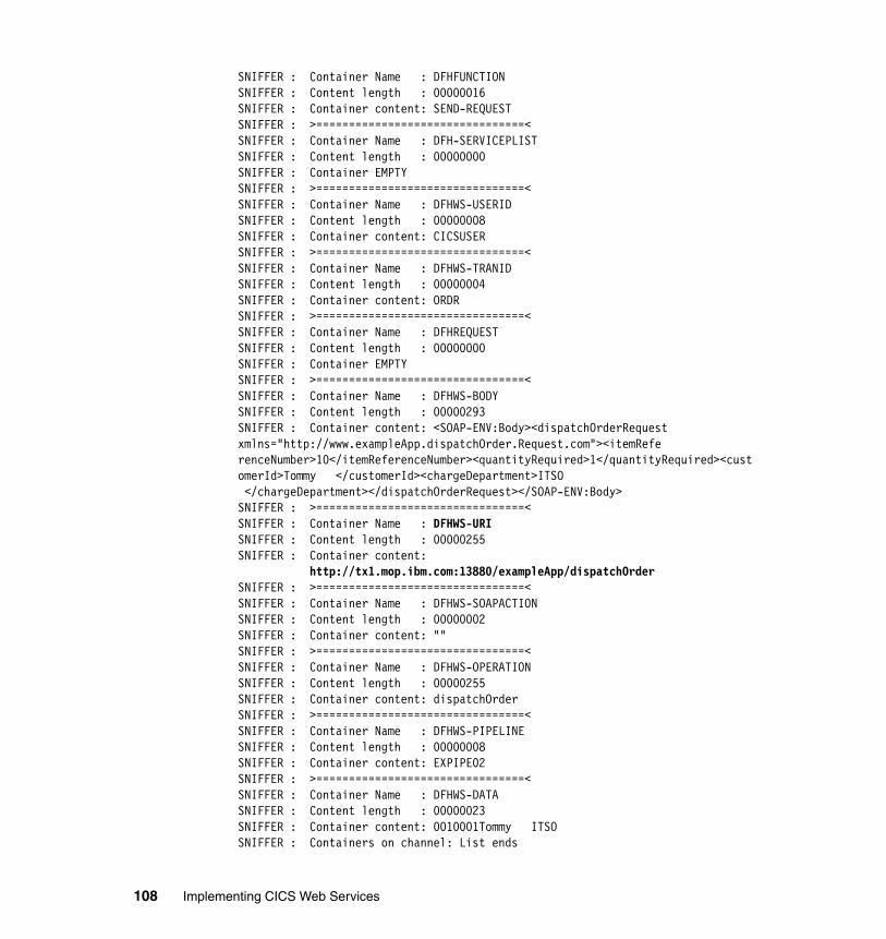
SNIFFER : Container Name : DFHFUNCTIONSNIFFER : Content length : 00000016SNIFFER : Container content: SEND-REQUESTSNIFFER : >================================<SNIFFER : Container Name : DFH-SERVICEPLISTSNIFFER : Content length : 00000000SNIFFER : Container EMPTYSNIFFER : >================================<SNIFFER : Container Name : DFHWS-USERIDSNIFFER : Content length : 00000008SNIFFER : Container content: CICSUSERSNIFFER : >================================<SNIFFER : Container Name : DFHWS-TRANIDSNIFFER : Content length : 00000004SNIFFER : Container content: ORDRSNIFFER : >================================<SNIFFER : Container Name : DFHREQUESTSNIFFER : Content length : 00000000SNIFFER : Container EMPTYSNIFFER : >================================<SNIFFER : Container Name : DFHWS-BODYSNIFFER : Content length : 00000293SNIFFER : Container content: <SOAP-ENV:Body><dispatchOrderRequest xmlns="http://www.exampleApp.dispatchOrder.Request.com"><itemReferenceNumber>10</itemReferenceNumber><quantityRequired>1</quantityRequired><customerId>Tommy </customerId><chargeDepartment>ITSO </chargeDepartment></dispatchOrderRequest></SOAP-ENV:Body>SNIFFER : >================================<SNIFFER : Container Name : DFHWS-URISNIFFER : Content length : 00000255SNIFFER : Container content:
http://tx1.mop.ibm.com:13880/exampleApp/dispatchOrderSNIFFER : >================================<SNIFFER : Container Name : DFHWS-SOAPACTIONSNIFFER : Content length : 00000002SNIFFER : Container content: ""SNIFFER : >================================<SNIFFER : Container Name : DFHWS-OPERATIONSNIFFER : Content length : 00000255SNIFFER : Container content: dispatchOrderSNIFFER : >================================<SNIFFER : Container Name : DFHWS-PIPELINESNIFFER : Content length : 00000008SNIFFER : Container content: EXPIPE02SNIFFER : >================================<SNIFFER : Container Name : DFHWS-DATASNIFFER : Content length : 00000023SNIFFER : Container content: 0010001Tommy ITSOSNIFFER : Containers on channel: List ends
108 Implementing CICS Web Services
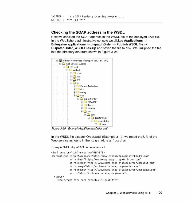
SNIFFER : in a SOAP header processing program.....SNIFFER : **** End ****
Checking the SOAP address in the WSDLNext we checked the SOAP address in the WSDL file of the deployed EAR file. In the WebSphere administrative console we clicked Applications → Enterprise applications → dispatchOrder → Publish WSDL file → DispatchOrder_WSDLFiles.zip and saved the file to disk. We unzipped the file into the directory structure shown in Figure 3-25.
Figure 3-25 ExampleAppDispatchOrder path
In the WSDL file dispatchOrder.wsdl (Example 3-19) we noted the URI of the Web service as found in the soap: address location.
Example 3-19 dispatchOrder sample wsdl
<?xml version="1.0" encoding="UTF-8"?><definitions targetNamespace="http://www.exampleApp.dispatchOrder.com"
xmlns:tns="http://www.exampleApp.dispatchOrder.com" xmlns:reqns="http://www.exampleApp.dispatchOrder.Request.com" xmlns:soap="http://schemas.xmlsoap.org/wsdl/soap/" xmlns:resns="http://www.exampleApp.dispatchOrder.Response.com" xmlns="http://schemas.xmlsoap.org/wsdl/">
<types> <xsd:schema attributeFormDefault="qualified"
Chapter 3. Web services using HTTP 109
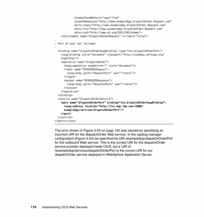
elementFormDefault="qualified" targetNamespace="http://www.exampleApp.dispatchOrder.Request.com" xmlns:reqns="http://www.exampleApp.dispatchOrder.Request.com" xmlns:tns="http://www.exampleApp.dispatchOrder.Request.com"xmlns:xsd="http://www.w3.org/2001/XMLSchema">
<xsd:element name="dispatchOrderRequest" nillable="false">.. Part of wsdl not included. <binding name="dispatchOrderSoapBinding" type="tns:dispatchOrderPort"> <soap:binding style="document" transport="http://schemas.xmlsoap.org/
soap/http"/> <operation name="dispatchOrder"> <soap:operation soapAction="" style="document"/> <input name="DFH0XODSRequest"> <soap:body parts="RequestPart" use="literal"/> </input> <output name="DFH0XODSResponse"> <soap:body parts="ResponsePart" use="literal"/> </output> </operation> </binding> <service name="dispatchOrderService"> <port name="dispatchOrderPort" binding="tns:dispatchOrderSoapBinding"> <soap:address location="http://tx1.mop.ibm.com:13880/
exampleApp/services/dispatchOrderPort"/> </port> </service></definitions>
The error shown in Figure 3-24 on page 105 was caused by specifying an incorrect URI for the dispatchOrder Web service. In the catalog manager configuration (Figure 3-24) we specified the URI /exampleApp/dispatchOrderPort for the outbound Web service. This is the correct URI for the dispatchOrder service provider deployed inside CICS, but a URI of /exampleApp/services/dispatchOrderPort is the correct URI for our dispatchOrder service deployed in WebSphere Application Server.
110 Implementing CICS Web Services
Chapter 4. Web services using WebSphere MQ
In this chapter we describe how we configured our test CICS environment to support Web services using WebSphere MQ as the transport mechanism.
4
© Copyright IBM Corp. 2006. All rights reserved. 111
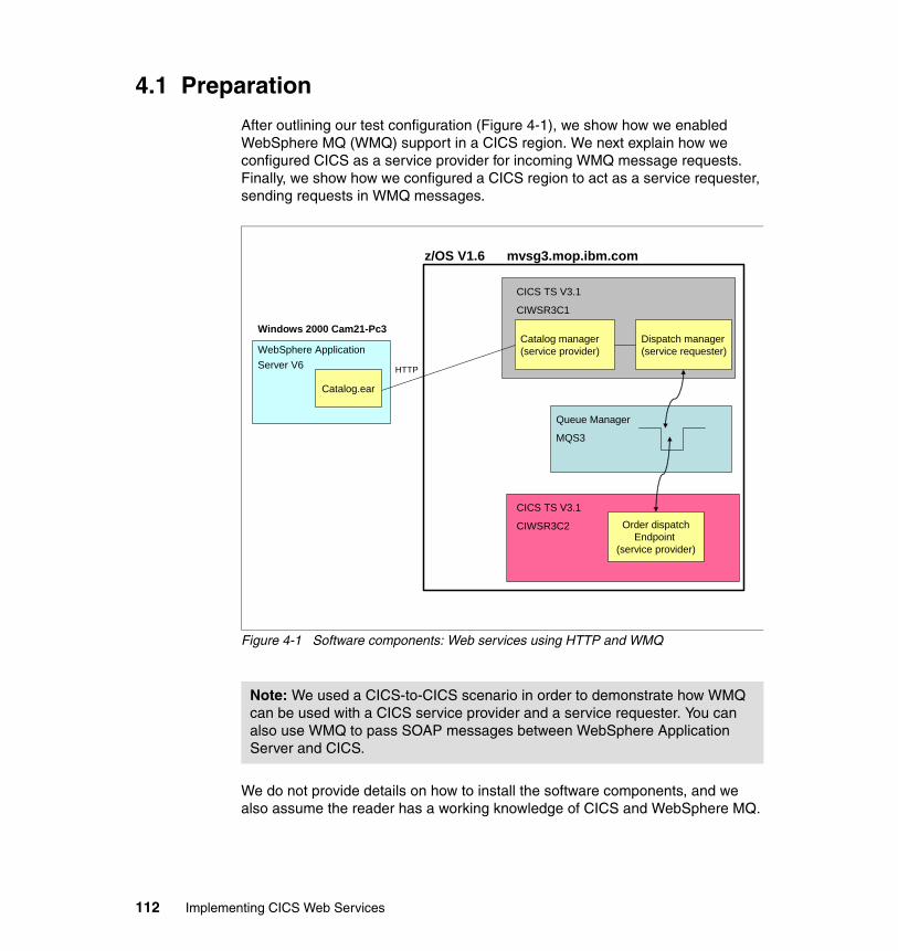
4.1 Preparation
After outlining our test configuration (Figure 4-1), we show how we enabled WebSphere MQ (WMQ) support in a CICS region. We next explain how we configured CICS as a service provider for incoming WMQ message requests. Finally, we show how we configured a CICS region to act as a service requester, sending requests in WMQ messages.
Figure 4-1 Software components: Web services using HTTP and WMQ
We do not provide details on how to install the software components, and we also assume the reader has a working knowledge of CICS and WebSphere MQ.
Note: We used a CICS-to-CICS scenario in order to demonstrate how WMQ can be used with a CICS service provider and a service requester. You can also use WMQ to pass SOAP messages between WebSphere Application Server and CICS.
CICS TS V3.1
CIWSR3C1
WebSphere Application Server V6
Windows 2000 Cam21-Pc3
z/OS V1.6 mvsg3.mop.ibm.com
CICS TS V3.1
CIWSR3C2
Catalog manager(service provider)
Dispatch manager(service requester)
Order dispatchEndpoint
(service provider)
Catalog.ear
HTTP
WMQQueue Manager
MQS3
112 Implementing CICS Web Services
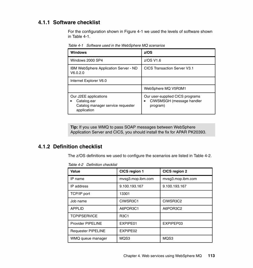
4.1.1 Software checklist
For the configuration shown in Figure 4-1 we used the levels of software shown in Table 4-1.
Table 4-1 Software used in the WebSphere MQ scenarios
4.1.2 Definition checklist
The z/OS definitions we used to configure the scenarios are listed in Table 4-2.
Table 4-2 Definition checklist
Windows z/OS
Windows 2000 SP4 z/OS V1.6
IBM WebSphere Application Server - ND V6.0.2.0
CICS Transaction Server V3.1
Internet Explorer V6.0
WebSphere MQ V5R3M1
Our J2EE applications� Catalog.ear
Catalog manager service requester application
Our user-supplied CICS programs� CIWSMSGH (message handler
program)
Tip: If you use WMQ to pass SOAP messages between WebSphere Application Server and CICS, you should install the fix for APAR PK20393.
Value CICS region 1 CICS region 2
IP name mvsg3.mop.ibm.com mvsg3.mop.ibm.com
IP address 9.100.193.167 9.100.193.167
TCP/IP port 13301
Job name CIWSR3C1 CIWSR3C2
APPLID A6POR3C1 A6POR3C2
TCPIPSERVICE R3C1
Provider PIPELINE EXPIPE01 EXPIPEP03
Requester PIPELINE EXPIPE02
WMQ queue manager MQS3 MQS3
Chapter 4. Web services using WebSphere MQ 113
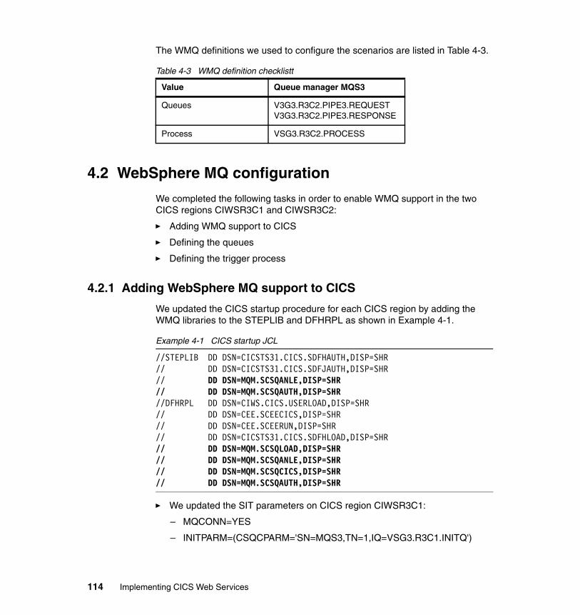
The WMQ definitions we used to configure the scenarios are listed in Table 4-3.
Table 4-3 WMQ definition checklistt
4.2 WebSphere MQ configuration
We completed the following tasks in order to enable WMQ support in the two CICS regions CIWSR3C1 and CIWSR3C2:
� Adding WMQ support to CICS
� Defining the queues
� Defining the trigger process
4.2.1 Adding WebSphere MQ support to CICS
We updated the CICS startup procedure for each CICS region by adding the WMQ libraries to the STEPLIB and DFHRPL as shown in Example 4-1.
Example 4-1 CICS startup JCL
//STEPLIB DD DSN=CICSTS31.CICS.SDFHAUTH,DISP=SHR // DD DSN=CICSTS31.CICS.SDFJAUTH,DISP=SHR // DD DSN=MQM.SCSQANLE,DISP=SHR // DD DSN=MQM.SCSQAUTH,DISP=SHR //DFHRPL DD DSN=CIWS.CICS.USERLOAD,DISP=SHR // DD DSN=CEE.SCEECICS,DISP=SHR // DD DSN=CEE.SCEERUN,DISP=SHR // DD DSN=CICSTS31.CICS.SDFHLOAD,DISP=SHR // DD DSN=MQM.SCSQLOAD,DISP=SHR // DD DSN=MQM.SCSQANLE,DISP=SHR // DD DSN=MQM.SCSQCICS,DISP=SHR // DD DSN=MQM.SCSQAUTH,DISP=SHR
� We updated the SIT parameters on CICS region CIWSR3C1:
– MQCONN=YES
– INITPARM=(CSQCPARM='SN=MQS3,TN=1,IQ=VSG3.R3C1.INITQ')
Value Queue manager MQS3
Queues V3G3.R3C2.PIPE3.REQUESTV3G3.R3C2.PIPE3.RESPONSE
Process VSG3.R3C2.PROCESS
114 Implementing CICS Web Services
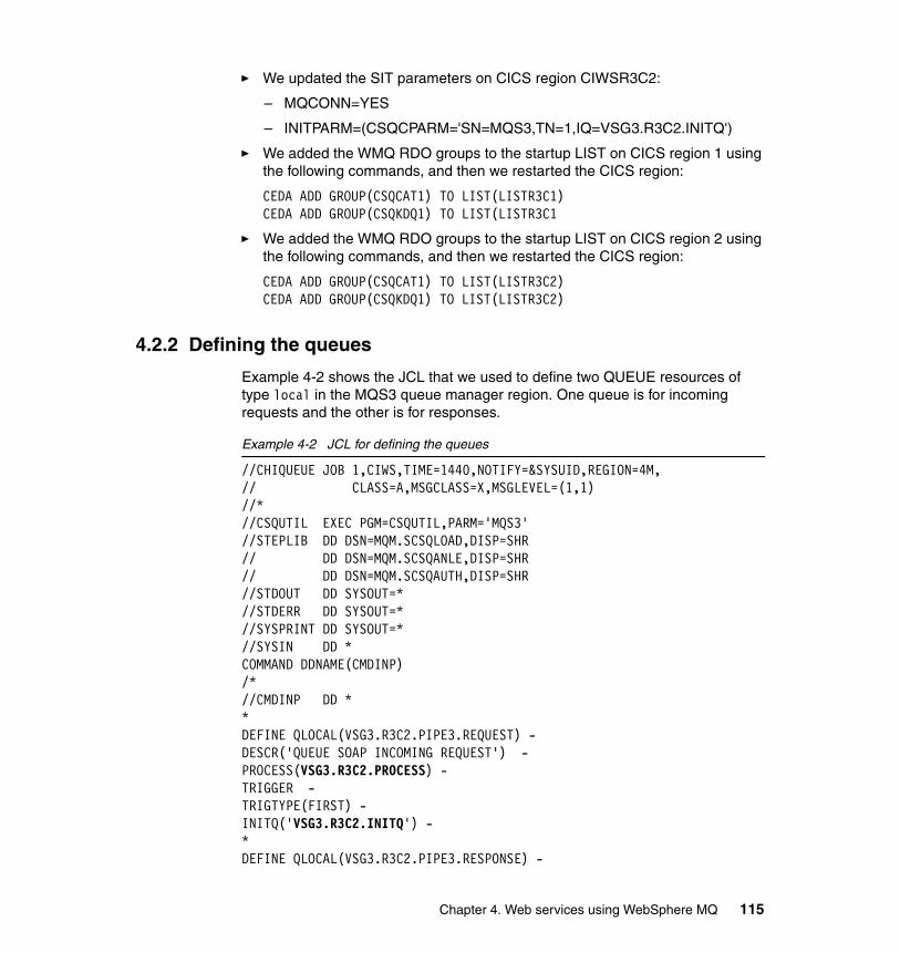
� We updated the SIT parameters on CICS region CIWSR3C2:
– MQCONN=YES
– INITPARM=(CSQCPARM='SN=MQS3,TN=1,IQ=VSG3.R3C2.INITQ')
� We added the WMQ RDO groups to the startup LIST on CICS region 1 using the following commands, and then we restarted the CICS region:
CEDA ADD GROUP(CSQCAT1) TO LIST(LISTR3C1)CEDA ADD GROUP(CSQKDQ1) TO LIST(LISTR3C1
� We added the WMQ RDO groups to the startup LIST on CICS region 2 using the following commands, and then we restarted the CICS region:
CEDA ADD GROUP(CSQCAT1) TO LIST(LISTR3C2)CEDA ADD GROUP(CSQKDQ1) TO LIST(LISTR3C2)
4.2.2 Defining the queues
Example 4-2 shows the JCL that we used to define two QUEUE resources of type local in the MQS3 queue manager region. One queue is for incoming requests and the other is for responses.
Example 4-2 JCL for defining the queues
//CHIQUEUE JOB 1,CIWS,TIME=1440,NOTIFY=&SYSUID,REGION=4M, // CLASS=A,MSGCLASS=X,MSGLEVEL=(1,1) //* //CSQUTIL EXEC PGM=CSQUTIL,PARM='MQS3' //STEPLIB DD DSN=MQM.SCSQLOAD,DISP=SHR // DD DSN=MQM.SCSQANLE,DISP=SHR // DD DSN=MQM.SCSQAUTH,DISP=SHR //STDOUT DD SYSOUT=* //STDERR DD SYSOUT=* //SYSPRINT DD SYSOUT=* //SYSIN DD * COMMAND DDNAME(CMDINP)/* //CMDINP DD * * DEFINE QLOCAL(VSG3.R3C2.PIPE3.REQUEST) - DESCR('QUEUE SOAP INCOMING REQUEST') - PROCESS(VSG3.R3C2.PROCESS) - TRIGGER - TRIGTYPE(FIRST) - INITQ('VSG3.R3C2.INITQ') - * DEFINE QLOCAL(VSG3.R3C2.PIPE3.RESPONSE) -
Chapter 4. Web services using WebSphere MQ 115
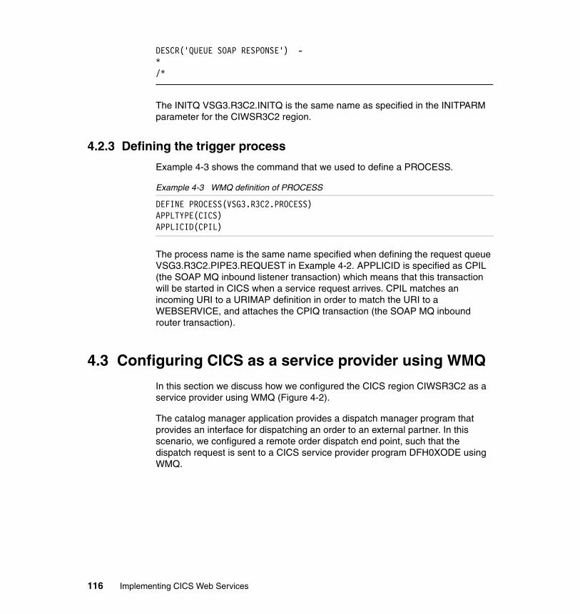
DESCR('QUEUE SOAP RESPONSE') - * /*
The INITQ VSG3.R3C2.INITQ is the same name as specified in the INITPARM parameter for the CIWSR3C2 region.
4.2.3 Defining the trigger process
Example 4-3 shows the command that we used to define a PROCESS.
Example 4-3 WMQ definition of PROCESS
DEFINE PROCESS(VSG3.R3C2.PROCESS)APPLTYPE(CICS)APPLICID(CPIL)
The process name is the same name specified when defining the request queue VSG3.R3C2.PIPE3.REQUEST in Example 4-2. APPLICID is specified as CPIL (the SOAP MQ inbound listener transaction) which means that this transaction will be started in CICS when a service request arrives. CPIL matches an incoming URI to a URIMAP definition in order to match the URI to a WEBSERVICE, and attaches the CPIQ transaction (the SOAP MQ inbound router transaction).
4.3 Configuring CICS as a service provider using WMQ
In this section we discuss how we configured the CICS region CIWSR3C2 as a service provider using WMQ (Figure 4-2).
The catalog manager application provides a dispatch manager program that provides an interface for dispatching an order to an external partner. In this scenario, we configured a remote order dispatch end point, such that the dispatch request is sent to a CICS service provider program DFH0XODE using WMQ.
116 Implementing CICS Web Services
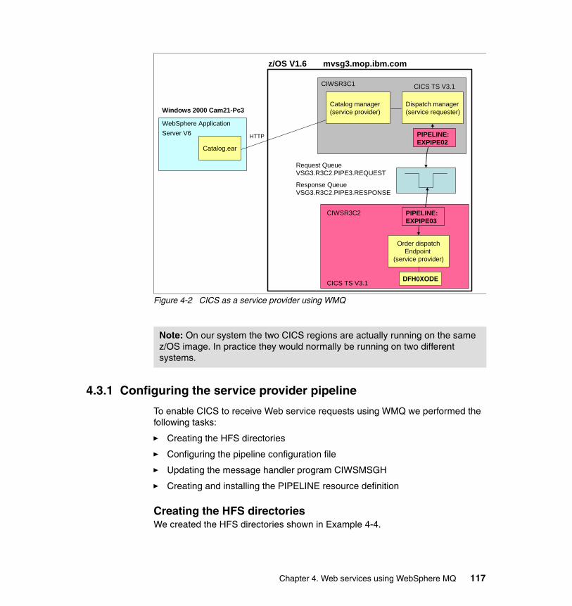
Figure 4-2 CICS as a service provider using WMQ
4.3.1 Configuring the service provider pipeline
To enable CICS to receive Web service requests using WMQ we performed the following tasks:
� Creating the HFS directories
� Configuring the pipeline configuration file
� Updating the message handler program CIWSMSGH
� Creating and installing the PIPELINE resource definition
Creating the HFS directoriesWe created the HFS directories shown in Example 4-4.
Note: On our system the two CICS regions are actually running on the same z/OS image. In practice they would normally be running on two different systems.
CIWSR3C1
WebSphere Application Server V6
Windows 2000 Cam21-Pc3
z/OS V1.6 mvsg3.mop.ibm.com
CIWSR3C2
Catalog manager(service provider)
Dispatch manager(service requester)
Order dispatchEndpoint
(service provider)
Catalog.ear
HTTP
Request Queue VSG3.R3C2.PIPE3.REQUEST
Response Queue VSG3.R3C2.PIPE3.RESPONSE
CICS TS V3.1
PIPELINE:EXPIPE02
PIPELINE:EXPIPE03
CICS TS V3.1 DFH0XODE
Chapter 4. Web services using WebSphere MQ 117
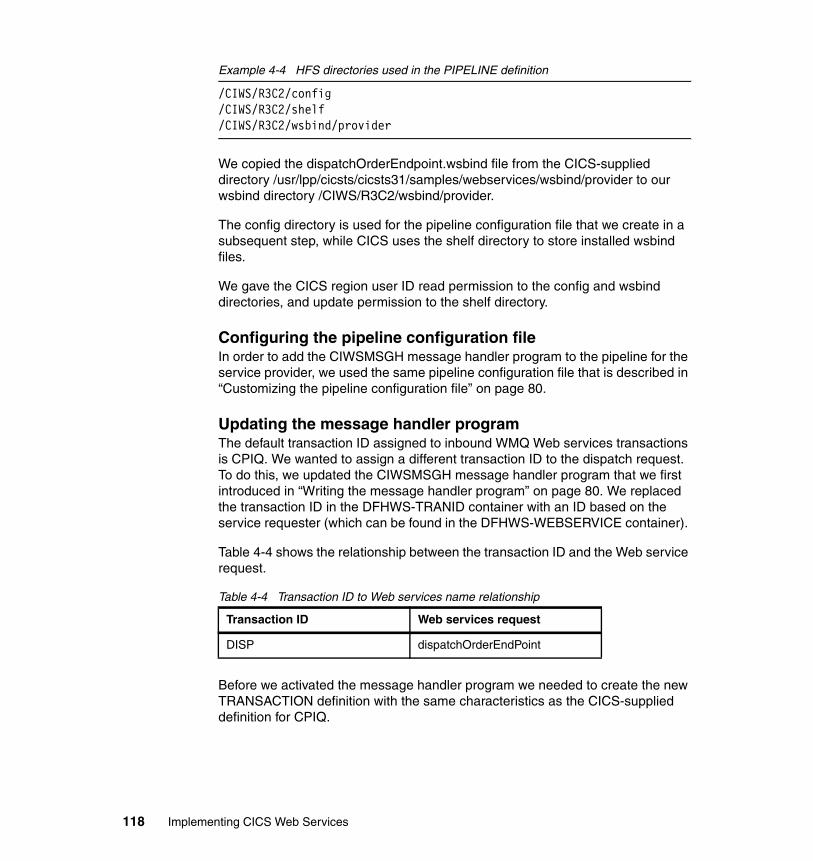
Example 4-4 HFS directories used in the PIPELINE definition
/CIWS/R3C2/config/CIWS/R3C2/shelf/CIWS/R3C2/wsbind/provider
We copied the dispatchOrderEndpoint.wsbind file from the CICS-supplied directory /usr/lpp/cicsts/cicsts31/samples/webservices/wsbind/provider to our wsbind directory /CIWS/R3C2/wsbind/provider.
The config directory is used for the pipeline configuration file that we create in a subsequent step, while CICS uses the shelf directory to store installed wsbind files.
We gave the CICS region user ID read permission to the config and wsbind directories, and update permission to the shelf directory.
Configuring the pipeline configuration fileIn order to add the CIWSMSGH message handler program to the pipeline for the service provider, we used the same pipeline configuration file that is described in “Customizing the pipeline configuration file” on page 80.
Updating the message handler programThe default transaction ID assigned to inbound WMQ Web services transactions is CPIQ. We wanted to assign a different transaction ID to the dispatch request. To do this, we updated the CIWSMSGH message handler program that we first introduced in “Writing the message handler program” on page 80. We replaced the transaction ID in the DFHWS-TRANID container with an ID based on the service requester (which can be found in the DFHWS-WEBSERVICE container).
Table 4-4 shows the relationship between the transaction ID and the Web service request.
Table 4-4 Transaction ID to Web services name relationship
Before we activated the message handler program we needed to create the new TRANSACTION definition with the same characteristics as the CICS-supplied definition for CPIQ.
Transaction ID Web services request
DISP dispatchOrderEndPoint
118 Implementing CICS Web Services
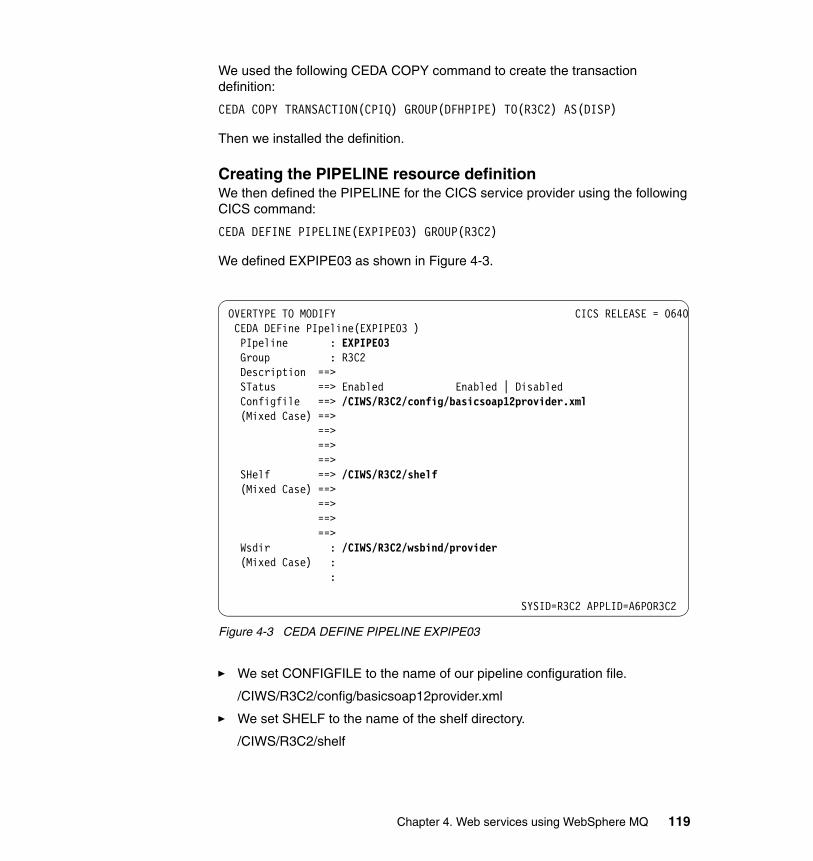
We used the following CEDA COPY command to create the transaction definition:
CEDA COPY TRANSACTION(CPIQ) GROUP(DFHPIPE) TO(R3C2) AS(DISP)
Then we installed the definition.
Creating the PIPELINE resource definitionWe then defined the PIPELINE for the CICS service provider using the following CICS command:
CEDA DEFINE PIPELINE(EXPIPE03) GROUP(R3C2)
We defined EXPIPE03 as shown in Figure 4-3.
Figure 4-3 CEDA DEFINE PIPELINE EXPIPE03
� We set CONFIGFILE to the name of our pipeline configuration file.
/CIWS/R3C2/config/basicsoap12provider.xml
� We set SHELF to the name of the shelf directory.
/CIWS/R3C2/shelf
OVERTYPE TO MODIFY CICS RELEASE = 0640 CEDA DEFine PIpeline(EXPIPE03 ) PIpeline : EXPIPE03 Group : R3C2 Description ==> STatus ==> Enabled Enabled | Disabled Configfile ==> /CIWS/R3C2/config/basicsoap12provider.xml (Mixed Case) ==> ==> ==> ==> SHelf ==> /CIWS/R3C2/shelf (Mixed Case) ==> ==> ==> ==> Wsdir : /CIWS/R3C2/wsbind/provider (Mixed Case) : :
SYSID=R3C2 APPLID=A6POR3C2
Chapter 4. Web services using WebSphere MQ 119
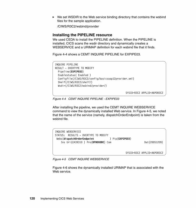
� We set WSDIR to the Web service binding directory that contains the wsbind files for the sample application.
/CIWS/R3C2/wsbind/provider
Installing the PIPELINE resourceWe used CEDA to install the PIPELINE definition. When the PIPELINE is installed, CICS scans the wsdir directory and dynamically creates a WEBSERVICE and a URIMAP definition for each wsbind file that it finds.
Figure 4-4 shows a CEMT INQUIRE PIPELINE for EXPIPE03.
Figure 4-4 CEMT INQUIRE PIPELINE - EXPIPE03
After installing the pipeline, we used the CEMT INQUIRE WEBSERVICE command to view the dynamically installed Web service. In Figure 4-5, we noted that the name of the service (namely, dispatchOrderEndpoint) is taken from the wsbind file.
Figure 4-5 CEMT INQUIRE WEBSERVICE
Figure 4-6 shows the dynamically installed URIMAP that is associated with the Web service.
INQUIRE PIPELINE RESULT - OVERTYPE TO MODIFY Pipeline(EXPIPE03) Enablestatus( Enabled ) Configfile(/CIWS/R3C2/config/basicsoap12provider.xml) Shelf(/CIWS/R3C2/shelf/) Wsdir(/CIWS/R3C2/wsbind/provider/)
SYSID=R3C2 APPLID=A6POR3C2
INQUIRE WEBSERVICE STATUS: RESULTS - OVERTYPE TO MODIFY Webs(dispatchOrderEndpoint ) Pip(EXPIPE03) Ins Uri(£439310 ) Pro(DFH0XODE) Com Dat(20051209)
SYSID=R3C2 APPLID=A6POR3C2
120 Implementing CICS Web Services
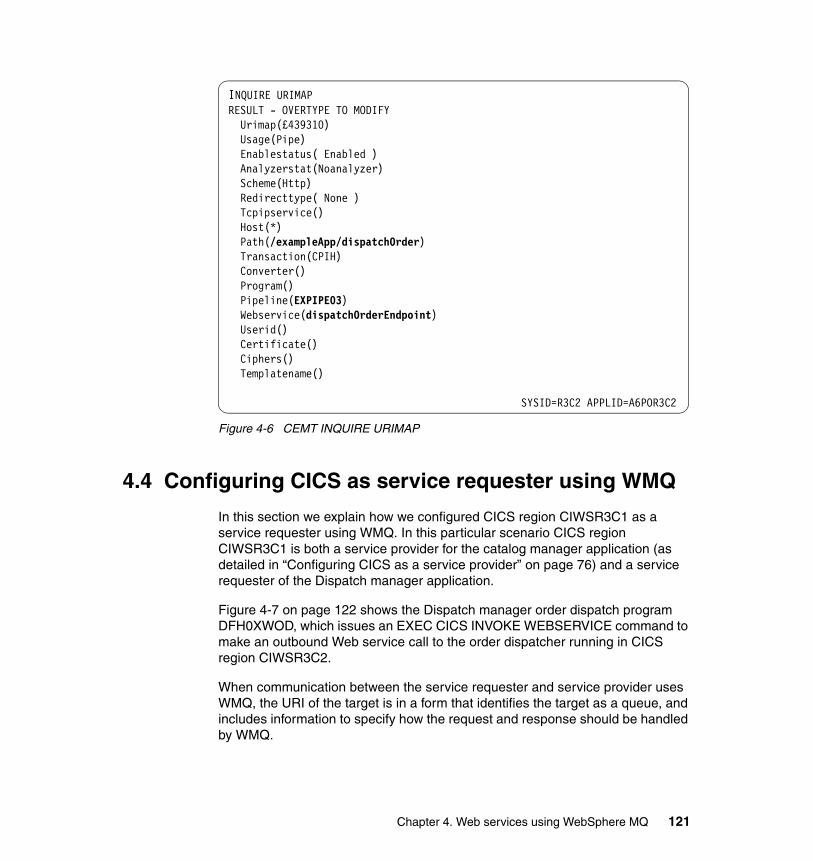
Figure 4-6 CEMT INQUIRE URIMAP
4.4 Configuring CICS as service requester using WMQ
In this section we explain how we configured CICS region CIWSR3C1 as a service requester using WMQ. In this particular scenario CICS region CIWSR3C1 is both a service provider for the catalog manager application (as detailed in “Configuring CICS as a service provider” on page 76) and a service requester of the Dispatch manager application.
Figure 4-7 on page 122 shows the Dispatch manager order dispatch program DFH0XWOD, which issues an EXEC CICS INVOKE WEBSERVICE command to make an outbound Web service call to the order dispatcher running in CICS region CIWSR3C2.
When communication between the service requester and service provider uses WMQ, the URI of the target is in a form that identifies the target as a queue, and includes information to specify how the request and response should be handled by WMQ.
INQUIRE URIMAP RESULT - OVERTYPE TO MODIFY Urimap(£439310) Usage(Pipe) Enablestatus( Enabled ) Analyzerstat(Noanalyzer) Scheme(Http) Redirecttype( None ) Tcpipservice() Host(*) Path(/exampleApp/dispatchOrder) Transaction(CPIH) Converter() Program() Pipeline(EXPIPE03) Webservice(dispatchOrderEndpoint) Userid() Certificate() Ciphers() Templatename()
SYSID=R3C2 APPLID=A6POR3C2
Chapter 4. Web services using WebSphere MQ 121
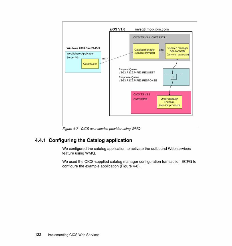
Figure 4-7 CICS as a service provider using WMQ
4.4.1 Configuring the Catalog application
We configured the catalog application to activate the outbound Web services feature using WMQ.
We used the CICS-supplied catalog manager configuration transaction ECFG to configure the example application (Figure 4-8).
CICS TS V3.1 CIWSR3C1
WebSphere Application Server V6
Windows 2000 Cam21-Pc3
z/OS V1.6 mvsg3.mop.ibm.com
CICS TS V3.1
CIWSR3C2
Catalog manager(service provider)
Dispatch managerDFH0XWOD
(service requester)
Order dispatchEndpoint
(service provider)
Catalog.ear
HTTP
Request Queue VSG3.R3C2.PIPE3.REQUEST
Response Queue VSG3.R3C2.PIPE3.RESPONSE
LINK
122 Implementing CICS Web Services
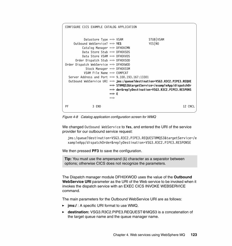
Figure 4-8 Catalog application configuration screen for WMQ
We changed Outbound WebService to Yes, and entered the URI of the service provider for our outbound service request:
jms:/queue?destination=VSG3.R3C2.PIPE3.REQUEST@MQS3&targetService=/exampleApp/dispatchOrder&replyDestination=VSG3.R3C2.PIPE3.RESPONSE
We then pressed PF3 to save the configuration.
The Dispatch manager module DFH0XWOD uses the value of the Outbound WebService URI parameter as the URI of the Web service to be invoked when it invokes the dispatch service with an EXEC CICS INVOKE WEBSERVICE command.
The main parameters for the Outbound WebService URI are as follows:
� jms:/ : A specific URI format to use WMQ.
� destination: VSG3.R3C2.PIPE3.REQUEST@MQS3 is a concatenation of the target queue name and the queue manager name.
Tip: You must use the ampersand (&) character as a separator between options; otherwise CICS does not recognize the parameters.
CONFIGURE CICS EXAMPLE CATALOG APPLICATION Datastore Type ==> VSAM STUB|VSAM Outbound WebService? ==> YES YES|NO Catalog Manager ==> DFH0XCMN Data Store Stub ==> DFH0XSDS Data Store VSAM ==> DFH0XVDS Order Dispatch Stub ==> DFH0XSOD Order Dispatch WebService ==> DFH0XWOD Stock Manager ==> DFH0XSSM VSAM File Name ==> EXMPCAT Server Address and Port ==> 9.100.193.167:13301 Outbound WebService URI ==> jms:/queue?destination=VSG3.R3C2.PIPE3.REQUE ==> ST@MQS3&targetService=/exampleApp/dispatchOr ==> der&replyDestination=VSG3.R3C2.PIPE3.RESPONS ==> E ==> PF 3 END 12 CNCL
Chapter 4. Web services using WebSphere MQ 123
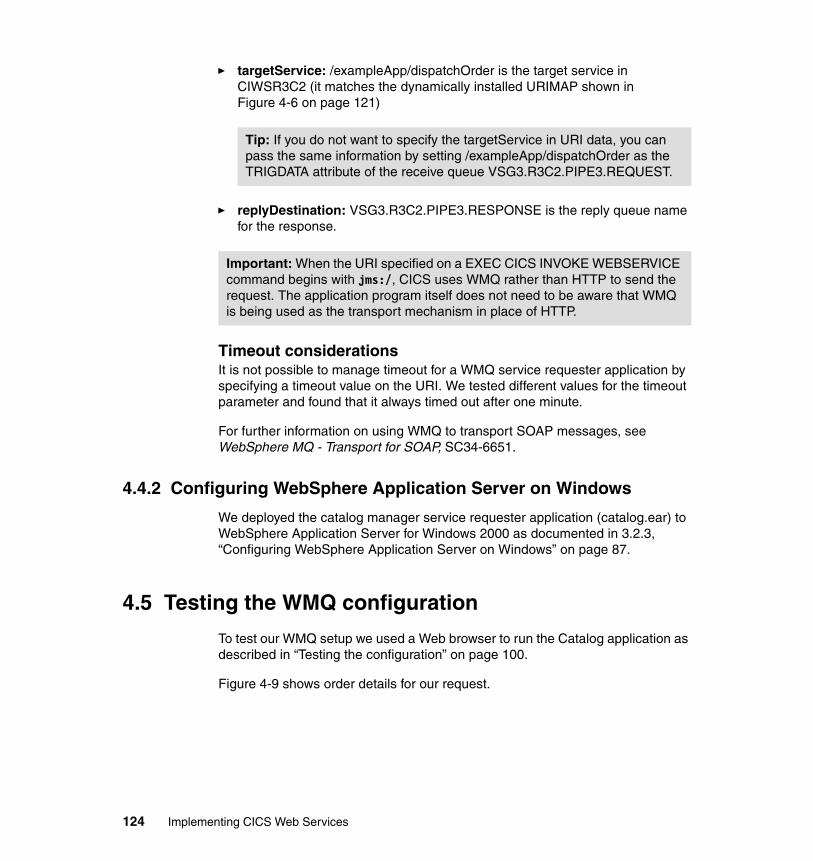
� targetService: /exampleApp/dispatchOrder is the target service in CIWSR3C2 (it matches the dynamically installed URIMAP shown in Figure 4-6 on page 121)
� replyDestination: VSG3.R3C2.PIPE3.RESPONSE is the reply queue name for the response.
Timeout considerationsIt is not possible to manage timeout for a WMQ service requester application by specifying a timeout value on the URI. We tested different values for the timeout parameter and found that it always timed out after one minute.
For further information on using WMQ to transport SOAP messages, see WebSphere MQ - Transport for SOAP, SC34-6651.
4.4.2 Configuring WebSphere Application Server on Windows
We deployed the catalog manager service requester application (catalog.ear) to WebSphere Application Server for Windows 2000 as documented in 3.2.3, “Configuring WebSphere Application Server on Windows” on page 87.
4.5 Testing the WMQ configuration
To test our WMQ setup we used a Web browser to run the Catalog application as described in “Testing the configuration” on page 100.
Figure 4-9 shows order details for our request.
Tip: If you do not want to specify the targetService in URI data, you can pass the same information by setting /exampleApp/dispatchOrder as the TRIGDATA attribute of the receive queue VSG3.R3C2.PIPE3.REQUEST.
Important: When the URI specified on a EXEC CICS INVOKE WEBSERVICE command begins with jms:/, CICS uses WMQ rather than HTTP to send the request. The application program itself does not need to be aware that WMQ is being used as the transport mechanism in place of HTTP.
124 Implementing CICS Web Services
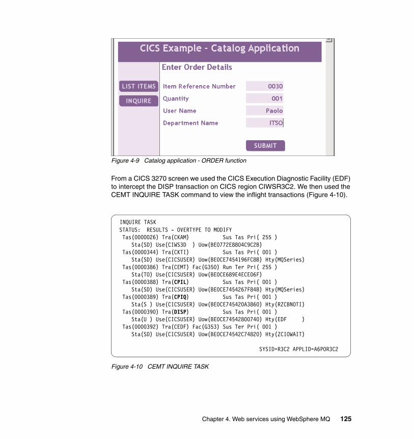
Figure 4-9 Catalog application - ORDER function
From a CICS 3270 screen we used the CICS Execution Diagnostic Facility (EDF) to intercept the DISP transaction on CICS region CIWSR3C2. We then used the CEMT INQUIRE TASK command to view the inflight transactions (Figure 4-10).
Figure 4-10 CEMT INQUIRE TASK
INQUIRE TASK STATUS: RESULTS - OVERTYPE TO MODIFY Tas(0000026) Tra(CKAM) Sus Tas Pri( 255 ) Sta(SD) Use(CIWS3D ) Uow(BE0772E8804C9C2B) Tas(0000344) Tra(CKTI) Sus Tas Pri( 001 ) Sta(SD) Use(CICSUSER) Uow(BE0CE7454196FC8B) Hty(MQSeries) Tas(0000386) Tra(CEMT) Fac(G350) Run Ter Pri( 255 ) Sta(TO) Use(CICSUSER) Uow(BE0CE689E4ECE06F) Tas(0000388) Tra(CPIL) Sus Tas Pri( 001 ) Sta(SD) Use(CICSUSER) Uow(BE0CE7454267F84B) Hty(MQSeries) Tas(0000389) Tra(CPIQ) Sus Tas Pri( 001 ) Sta(S ) Use(CICSUSER) Uow(BE0CE745420A3860) Hty(RZCBNOTI) Tas(0000390) Tra(DISP) Sus Tas Pri( 001 ) Sta(U ) Use(CICSUSER) Uow(BE0CE74542800740) Hty(EDF ) Tas(0000392) Tra(CEDF) Fac(G353) Sus Ter Pri( 001 ) Sta(SD) Use(CICSUSER) Uow(BE0CE74542C74820) Hty(ZCIOWAIT)
SYSID=R3C2 APPLID=A6POR3C2
Chapter 4. Web services using WebSphere MQ 125
Figure 4-10 shows the inflight transactions:
� The SOAP MQ inbound listener transaction (CPIL)
� The SOAP MQ inbound router transaction (CPIQ)
� The transaction used for running the business logic program (DISP)
After ending the EDF session, we received the ORDER SUCCESFULLY PLACED response in the browser.
We noted the SYSPRINT messages by the CIWSMSGH message handler for CICS region CIWSR3C2 (Example 4-5).
Example 4-5 CICS CIWSR3C2 - SYSPRINT
CIWSMSGH: >================================< CIWSMSGH: Container Name: : DFHWS-WEBSERVICE CIWSMSGH: Container content: dispatchOrderEndpoint CIWSMSGH: ---------------------------------- CIWSMSGH: Container Name: : DFHWS-TRANID CIWSMSGH: Container content: DISP CIWSMSGH: ---------------------------------- CIWSMSGH: Container Name: : DFHWS-URI CIWSMSGH: Container content: wmq:VSG3.R3C2.PIPE3.REQUEST/exampleApp/dispatchOrder
Note that after the request for the dispatchOrderEndpoint service arrives, the message handler changes the transaction ID to DISP. In particular, note that the DFHWS-URI container shows the URI in WMQ format.
4.6 High availability with WMQ
In 3.4, “Configuring for high availability” on page 101 we outlined how HTTP Web service requests can be balanced across multiple CICS regions in order to provide a high availability configuration. Here we take a brief look at how WMQ Web service requests can be balanced across multiple CICS regions.
On page 101, we also discussed how once a request is received by a specific CICS region, it can be dynamically routed within a CICSPlex. These transaction and program routing mechanisms can be used irrespective of how the SOAP message is transported.
The principal areas for consideration when designing a high availability configuration for WebSphere MQ are:
� How to share access to queues across multiple CICS regions
126 Implementing CICS Web Services
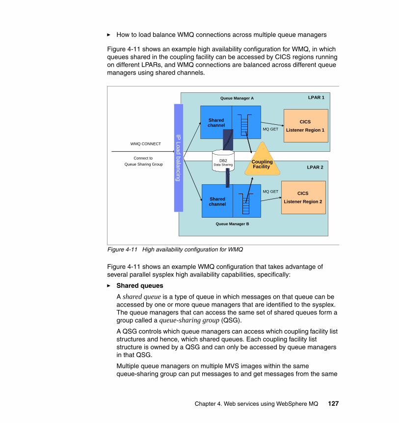
� How to load balance WMQ connections across multiple queue managers
Figure 4-11 shows an example high availability configuration for WMQ, in which queues shared in the coupling facility can be accessed by CICS regions running on different LPARs, and WMQ connections are balanced across different queue managers using shared channels.
Figure 4-11 High availability configuration for WMQ
Figure 4-11 shows an example WMQ configuration that takes advantage of several parallel sysplex high availability capabilities, specifically:
� Shared queues
A shared queue is a type of queue in which messages on that queue can be accessed by one or more queue managers that are identified to the sysplex. The queue managers that can access the same set of shared queues form a group called a queue-sharing group (QSG).
A QSG controls which queue managers can access which coupling facility list structures and hence, which shared queues. Each coupling facility list structure is owned by a QSG and can only be accessed by queue managers in that QSG.
Multiple queue managers on multiple MVS images within the same queue-sharing group can put messages to and get messages from the same
Sharedchannel
Connect toQueue Sharing Group
Queue Manager A
DB2Data Sharing
Sharedchannel
MQ GET
MQ GET
WMQ CONNECT
LPAR 1
CICS
Listener Region 2
CICS
Listener Region 1IP Load balancingQueue Manager B
LPAR 2CouplingFacility
Chapter 4. Web services using WebSphere MQ 127
shared queue. This is achieved by storing all the messages in a shared queue in the same coupling facility list structure.
Multiple queue managers on multiple MVS images within the same queue-sharing group can access the same WebSphere MQ objects. This is achieved by storing the object definitions in tables of a DB2 data-sharing group.
The use of shared queues provides a highly available solution because the failure of a single MVS image does not prevent access to shared queues. Another benefit is a capability to implement pull workload balancing. It means that by defining the input queue of an application (such as a CICS service provider application) as a shared queue, you make any message put to that queue available to be retrieved by any queue manager in the queue-sharing group.
� Shared channels
The advantage of using shared channels is high availability when compared to being connected to a single queue manager. An inbound channel is classed as shared if it is connected to the queue manager through a group listener. A group listener is an additional task started on each channel initiator in the queue-sharing group. This task listens on an ip address/port combination, specific to that queue manager, known as its group address. Each group address can then be registered with an IP routing mechanism such as Sysplex Distributor.
� Sysplex Distributor
Sysplex Distributor is designed to address the requirement of one single network-visible IP address for a service. Sysplex distributor can be used to map a queue-sharing group-wide generic IP address/port to a specific group address.
For more information on configuring high availability with WMQ refer to WebSphere MQ in a z/OS Parallel Sysplex Environment, SG24-6864.
128 Implementing CICS Web Services
Chapter 5. Connecting CICS to the service integration bus
This chapter introduces the service integration bus (or bus) and the benefits of connecting your CICS Web service applications to a bus. It then goes on to explain the steps involved in accessing a CICS Web service via a bus.
5
© Copyright IBM Corp. 2006. All rights reserved. 129
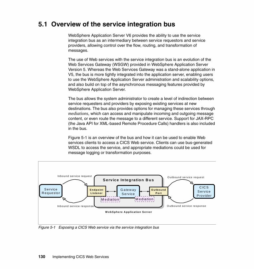
5.1 Overview of the service integration bus
WebSphere Application Server V6 provides the ability to use the service integration bus as an intermediary between service requestors and service providers, allowing control over the flow, routing, and transformation of messages.
The use of Web services with the service integration bus is an evolution of the Web Services Gateway (WSGW) provided in WebSphere Application Server Version 5. Whereas the Web Services Gateway was a stand-alone application in V5, the bus is more tightly integrated into the application server, enabling users to use the WebSphere Application Server administration and scalability options, and also build on top of the asynchronous messaging features provided by WebSphere Application Server.
The bus allows the system administrator to create a level of indirection between service requesters and providers by exposing existing services at new destinations. The bus also provides options for managing these services through mediations, which can access and manipulate incoming and outgoing message content, or even route the message to a different service. Support for JAX-RPC (the Java API for XML-based Remote Procedure Calls) handlers is also included in the bus.
Figure 5-1 is an overview of the bus and how it can be used to enable Web services clients to access a CICS Web service. Clients can use bus-generated WSDL to access the service, and appropriate mediations could be used for message logging or transformation purposes.
Figure 5-1 Exposing a CICS Web service via the service integration bus
W S -S ec urity b in d in gsW S -S ec urity co n fig ura tio n
W S -S ecu rity b in d in g s
W S -S ecu rity co n fig u ra tio n
O u tb o u n dP o rt
S erv ice R equesto r
S erv ice In teg ra tio n B u s
C IC SS erv iceP rov ide r
E n d p o in tL is ten er
Inbound se rv ice reques t
Inbound se rv ice respon se
O u tb ound se rv ice reques t
O utbo und se rv ice response
G a tew ayS erv ice
W eb S ph ere A pp lica tio n S erver
M ed ia tionM ed ia tion
130 Implementing CICS Web Services
It is possible for CICS to interoperate with the bus both as a service provider and as a service requester. The use of bus-generated WSDL means that the service requester does not need to know the location of the CICS service provider; it only needs to know the location of the bus. The bus itself knows the location of the CICS service provider. Similarly, a CICS service requester does not need to know the location of the service provider; it only needs to know the location of the bus.
Among the components you may come across in discussions and implementations of buses, are the following:
� Bus: The “intelligent network” on which inbound and outbound services and gateway resources are defined.
� Endpoint listener: Entry points to the bus for Web services clients. Endpoint listeners allow clients to connect over SOAP/HTTP or SOAP/JMS. They are associated with inbound services and gateway resources.
� Inbound service: Destinations within the bus exposed as Web services (a gateway service can be thought of as a special kind of inbound service).
� Outbound service: Destinations within the bus that represent external Web services. CICS is invoked via an outbound service.
� Gateway instance: Enables a user to create gateway services.
� Gateway service: Exposes a target Web service that is external to the bus, as a bus-managed Web service. (We will be deploying our CICS service provider application as a gateway service.)
� Mediation: A stateless session EJB™ attached to a service destination that can apply processing to messages that pass through it, for example, logging or message transformation.
� JAX-RPC handler: JAX-RPC is a J2EE standard for intercepting and manipulating Web services messages.
5.1.1 Why you would connect CICS to a bus
We describe here some reasons why you might want to use the Web services features of a WebSphere Application Server service integration bus with your CICS service provider and service requester applications.
� Service location independence
You may not want to publish details of the location (TCP/IP addresses) of your CICS service provider applications. Indirect access from the service requester to the service provider via a bus means that a change in the address of the service provider requires a configuration update of the bus, but
Chapter 5. Connecting CICS to the service integration bus 131
not the service requesters. This service location independence enables a more flexible configuration and eases the task of service administration.
� Securely externalizing existing applications
Businesses can deploy CICS Web services as gateway services on the bus. This enables applications deployed on a CICS deep inside an enterprise to be made available as Web services on the Internet to customers, suppliers, and business partners. You can then use the bus to secure your CICS Web services applications, using security options that are not currently available when the service requester accesses CICS directly (see “Securing CICS Web services via the service integration bus” on page 174).
� Return on investment
Any number of business partners can reuse an existing CICS application process that you make available as a gateway service using the bus. This provides great opportunity for the reuse of existing assets.
� Protocol transformation
The bus allows a protocol switch between the service requester and the service provider. For example, if CICS exposes a service provider application using HTTP as the transport mechanism, a service requester accessing CICS via the bus can connect to the bus using JMS, and the bus will transparently forward the request on to CICS over HTTP. This function is invaluable for ensuring smooth interoperability between businesses that may implement Web services with different transport mechanisms.
� Standards-based integration
The bus provides support for the major Web services standards, giving businesses confidence that they can use it to build flexible and interoperable solutions.
5.2 Preparation
After outlining our test configuration (Figure 5-2), we show how we:
� Configured CICS for a gateway service
� Created a gateway service on the bus
� Tested access to a CICS service provider application via the bus
132 Implementing CICS Web Services
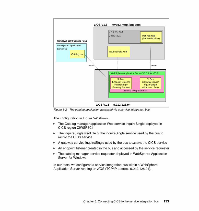
Figure 5-2 The catalog application accessed via a service integration bus
The configuration in Figure 5-2 shows:
� The Catalog manager application Web service inquireSingle deployed in CICS region CIWSR3C1
� The inquireSingle.wsdl file of the inquireSingle service used by the bus to locate the CICS service
� A gateway service inquireSingle used by the bus to access the CICS service
� An endpoint listener created in the bus and accessed by the service requester
� The catalog manager service requester deployed in WebSphere Application Server for Windows
In our tests, we configured a service integration bus within a WebSphere Application Server running on z/OS (TCP/IP address 9.212.128.94).
CICS TS V3.1
CIWSR3C1
WebSphere Application Server V6
Windows 2000 Cam21-Pc11
z/OS V1.6 mvsg3.mop.ibm.com
z/OS V1.6 9.212.128.94
WebSphere Application Server V6.0.1 for z/OS
inquireSingle.wsdl
inquireSingle(ServiceProvider)
SI Bus Gateway Service
inquireSingle(Outbound Port)
Catalog.ear
HTTP HTTP
SI Bus Endpoint Listener
inquireSingle(Gateway Service)
Service Integration Bus
Chapter 5. Connecting CICS to the service integration bus 133
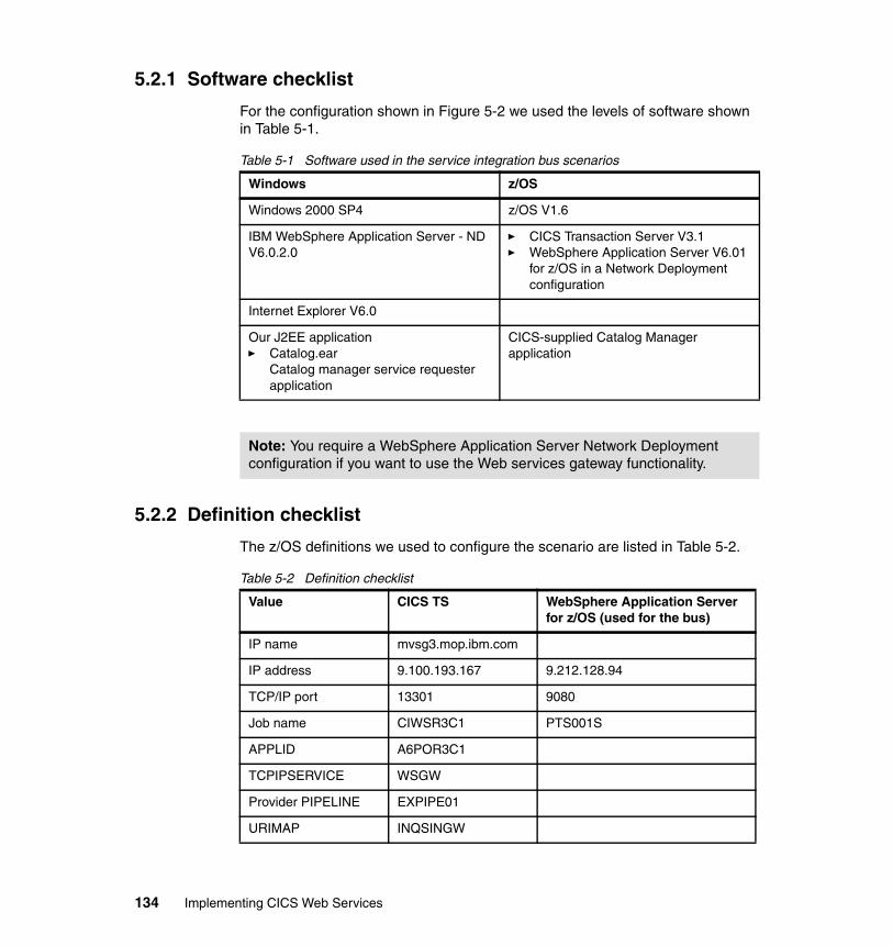
5.2.1 Software checklist
For the configuration shown in Figure 5-2 we used the levels of software shown in Table 5-1.
Table 5-1 Software used in the service integration bus scenarios
5.2.2 Definition checklist
The z/OS definitions we used to configure the scenario are listed in Table 5-2.
Table 5-2 Definition checklist
Windows z/OS
Windows 2000 SP4 z/OS V1.6
IBM WebSphere Application Server - ND V6.0.2.0
� CICS Transaction Server V3.1� WebSphere Application Server V6.01
for z/OS in a Network Deployment configuration
Internet Explorer V6.0
Our J2EE application� Catalog.ear
Catalog manager service requester application
CICS-supplied Catalog Manager application
Note: You require a WebSphere Application Server Network Deployment configuration if you want to use the Web services gateway functionality.
Value CICS TS WebSphere Application Server for z/OS (used for the bus)
IP name mvsg3.mop.ibm.com
IP address 9.100.193.167 9.212.128.94
TCP/IP port 13301 9080
Job name CIWSR3C1 PTS001S
APPLID A6POR3C1
TCPIPSERVICE WSGW
Provider PIPELINE EXPIPE01
URIMAP INQSINGW
134 Implementing CICS Web Services
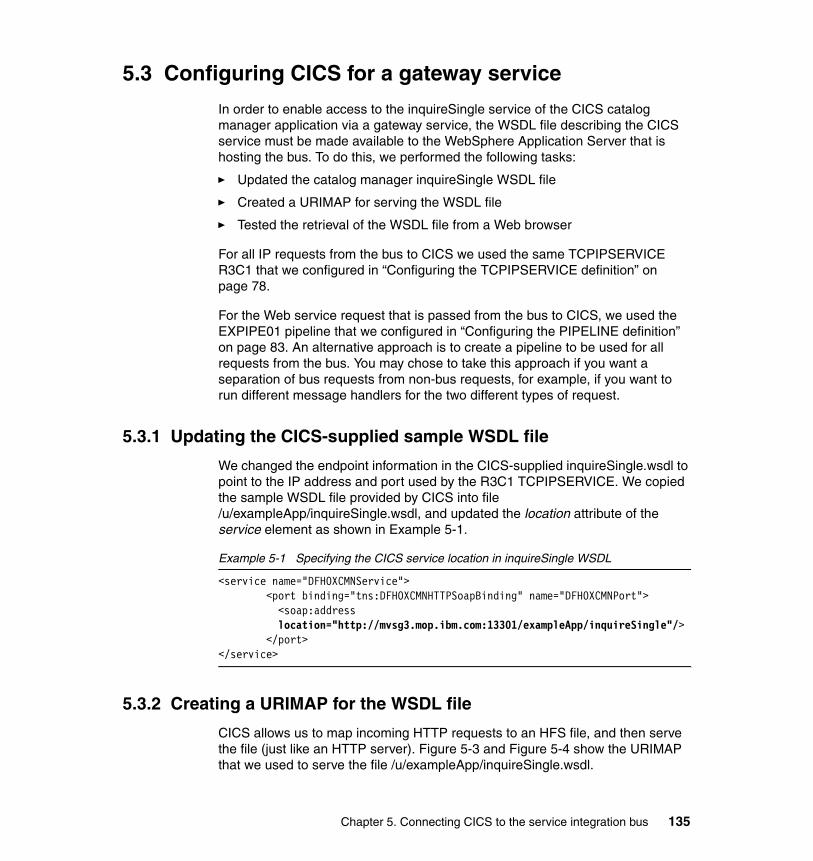
5.3 Configuring CICS for a gateway service
In order to enable access to the inquireSingle service of the CICS catalog manager application via a gateway service, the WSDL file describing the CICS service must be made available to the WebSphere Application Server that is hosting the bus. To do this, we performed the following tasks:
� Updated the catalog manager inquireSingle WSDL file
� Created a URIMAP for serving the WSDL file
� Tested the retrieval of the WSDL file from a Web browser
For all IP requests from the bus to CICS we used the same TCPIPSERVICE R3C1 that we configured in “Configuring the TCPIPSERVICE definition” on page 78.
For the Web service request that is passed from the bus to CICS, we used the EXPIPE01 pipeline that we configured in “Configuring the PIPELINE definition” on page 83. An alternative approach is to create a pipeline to be used for all requests from the bus. You may chose to take this approach if you want a separation of bus requests from non-bus requests, for example, if you want to run different message handlers for the two different types of request.
5.3.1 Updating the CICS-supplied sample WSDL file
We changed the endpoint information in the CICS-supplied inquireSingle.wsdl to point to the IP address and port used by the R3C1 TCPIPSERVICE. We copied the sample WSDL file provided by CICS into file /u/exampleApp/inquireSingle.wsdl, and updated the location attribute of the service element as shown in Example 5-1.
Example 5-1 Specifying the CICS service location in inquireSingle WSDL
<service name="DFH0XCMNService"> <port binding="tns:DFH0XCMNHTTPSoapBinding" name="DFH0XCMNPort">
<soap:address location="http://mvsg3.mop.ibm.com:13301/exampleApp/inquireSingle"/>
</port></service>
5.3.2 Creating a URIMAP for the WSDL file
CICS allows us to map incoming HTTP requests to an HFS file, and then serve the file (just like an HTTP server). Figure 5-3 and Figure 5-4 show the URIMAP that we used to serve the file /u/exampleApp/inquireSingle.wsdl.
Chapter 5. Connecting CICS to the service integration bus 135
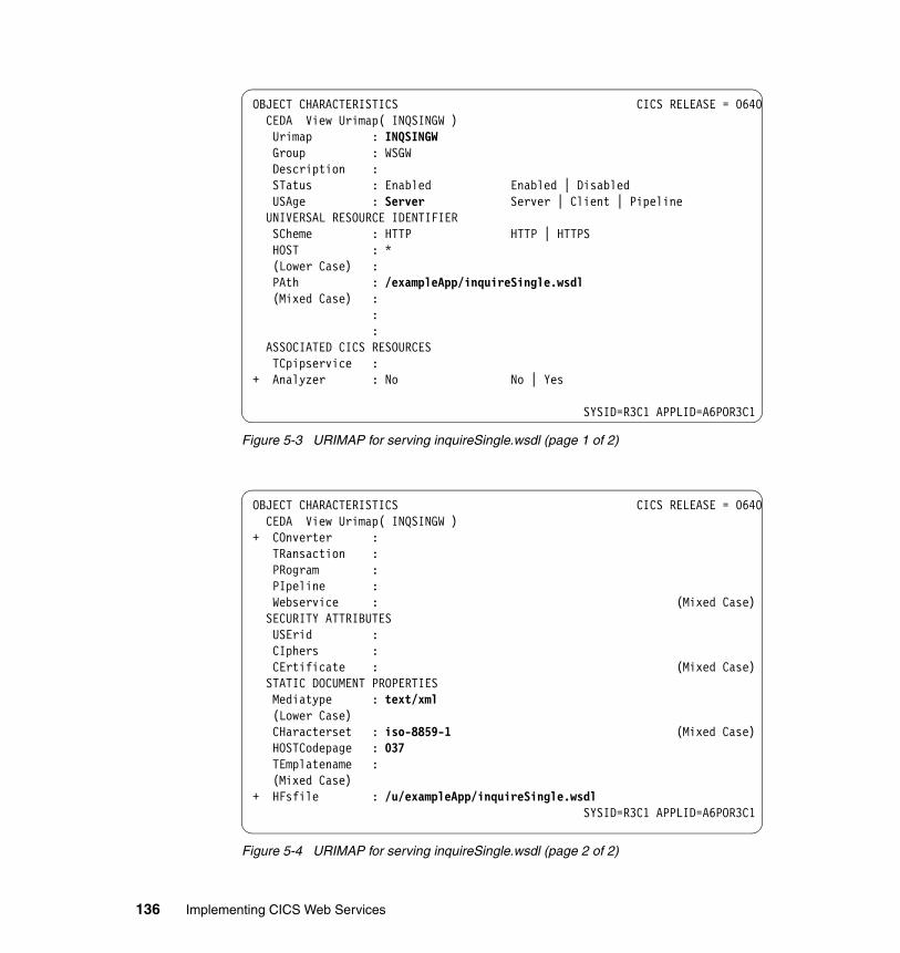
Figure 5-3 URIMAP for serving inquireSingle.wsdl (page 1 of 2)
Figure 5-4 URIMAP for serving inquireSingle.wsdl (page 2 of 2)
OBJECT CHARACTERISTICS CICS RELEASE = 0640 CEDA View Urimap( INQSINGW ) Urimap : INQSINGW Group : WSGW Description : STatus : Enabled Enabled | Disabled USAge : Server Server | Client | Pipeline UNIVERSAL RESOURCE IDENTIFIER SCheme : HTTP HTTP | HTTPS HOST : * (Lower Case) : PAth : /exampleApp/inquireSingle.wsdl (Mixed Case) :
: : ASSOCIATED CICS RESOURCES TCpipservice : + Analyzer : No No | Yes
SYSID=R3C1 APPLID=A6POR3C1
OBJECT CHARACTERISTICS CICS RELEASE = 0640 CEDA View Urimap( INQSINGW ) + COnverter : TRansaction : PRogram : PIpeline : Webservice : (Mixed Case) SECURITY ATTRIBUTES USErid : CIphers : CErtificate : (Mixed Case) STATIC DOCUMENT PROPERTIES Mediatype : text/xml (Lower Case) CHaracterset : iso-8859-1 (Mixed Case) HOSTCodepage : 037 TEmplatename : (Mixed Case) + HFsfile : /u/exampleApp/inquireSingle.wsdl
SYSID=R3C1 APPLID=A6POR3C1
136 Implementing CICS Web Services
We used the following values:
� URIMAP name was set to INQSINGW.
� USAGE was set to SERVER, indicating that CICS is to act like an HTTP server, in this case serving a static file.
� SCHEME was set to HTTP because no transport security was being used.
� HOST was set to an asterisk (*) to indicate that the URIMAP definition is to be used as a wildcard to match on any host name.
� PATH was set to /exampleApp/inquireSingle.wsdl. Together with the HOST and SCHEME values this means that the URIMAP resource will cater to any HTTP request of the form http://*/exampleApp/inquireSingle.wsdl.
� TCPIPSERVICE was not set so that the URIMAP definition applies to a request on any inbound port.
� MEDIATYPE was set to text/xml to indicate that an XML file is being served. CICS creates a Content-Type header for the response using the value of this attribute.
� CHARACTERSET was set to iso-8859-1 so that CICS converts the body of the response that is sent to the bus into ASCII.
� HOSTCODEPAGE was set to 037 to indicate the EBCDIC code page in which the WSDL file is encoded. This information is needed by CICS to perform code page conversion for the body of the response.
� HFSFILE was set to /u/exampleApp/inquireSingle.wsdl, which is the fully qualified name of the HFS file containing the WSDL.
� All other values were allowed to default.
5.3.3 Testing the retrieval of the WSDL file from a Web browser
Prior to configuring the gateway service on the bus, we tested the CICS configuration by retrieving the inquireSingle.wsdl file from a Web browser using the URL:
http://mvsg3.mop.ibm.com:13301/exampleApp/inquireSingle.wsdl
Figure 5-5 shows the WSDL file displayed in the Web browser.
Note: If the MEDIATYPE attribute specifies a text type, the CHARACTERSET and HOSTCODEPAGE attributes must also be specified so that code page conversion can take place.
Chapter 5. Connecting CICS to the service integration bus 137
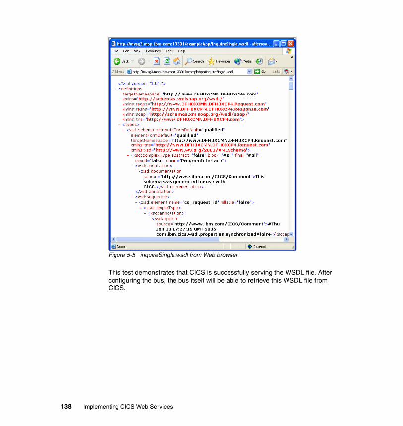
Figure 5-5 inquireSingle.wsdl from Web browser
This test demonstrates that CICS is successfully serving the WSDL file. After configuring the bus, the bus itself will be able to retrieve this WSDL file from CICS.
138 Implementing CICS Web Services
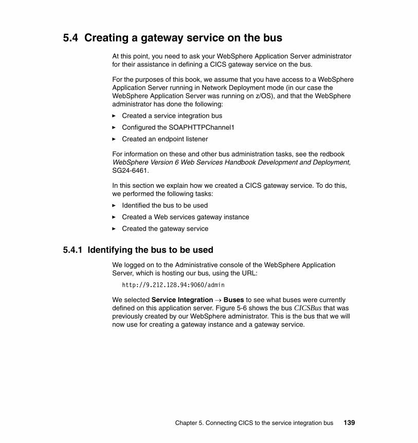
5.4 Creating a gateway service on the bus
At this point, you need to ask your WebSphere Application Server administrator for their assistance in defining a CICS gateway service on the bus.
For the purposes of this book, we assume that you have access to a WebSphere Application Server running in Network Deployment mode (in our case the WebSphere Application Server was running on z/OS), and that the WebSphere administrator has done the following:
� Created a service integration bus
� Configured the SOAPHTTPChannel1
� Created an endpoint listener
For information on these and other bus administration tasks, see the redbook WebSphere Version 6 Web Services Handbook Development and Deployment, SG24-6461.
In this section we explain how we created a CICS gateway service. To do this, we performed the following tasks:
� Identified the bus to be used
� Created a Web services gateway instance
� Created the gateway service
5.4.1 Identifying the bus to be used
We logged on to the Administrative console of the WebSphere Application Server, which is hosting our bus, using the URL:
http://9.212.128.94:9060/admin
We selected Service Integration → Buses to see what buses were currently defined on this application server. Figure 5-6 shows the bus CICSBus that was previously created by our WebSphere administrator. This is the bus that we will now use for creating a gateway instance and a gateway service.
Chapter 5. Connecting CICS to the service integration bus 139
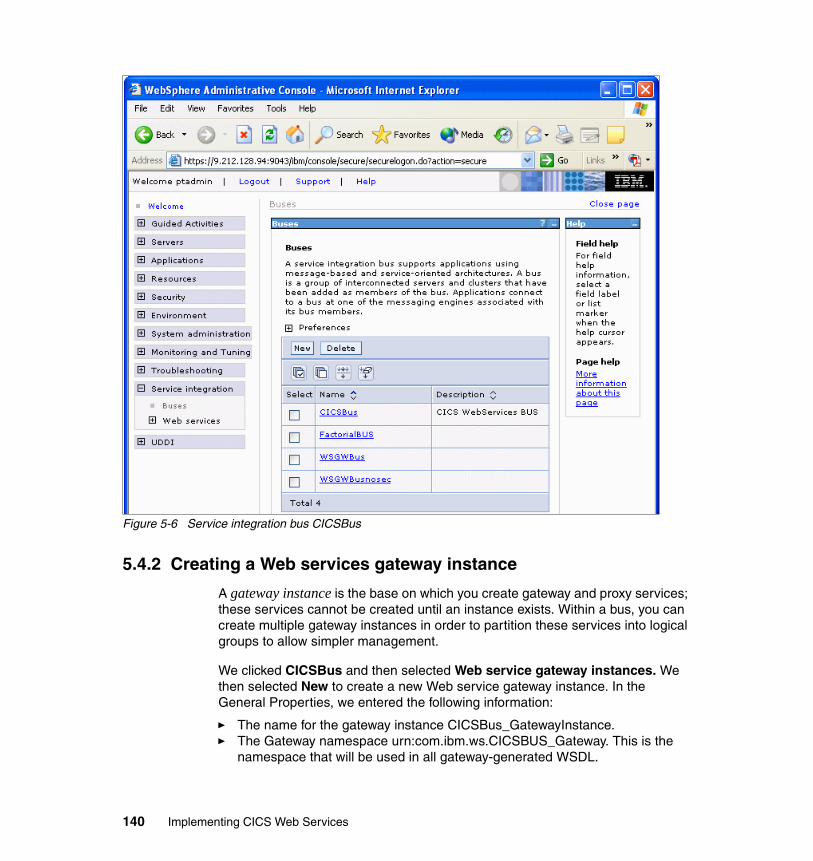
Figure 5-6 Service integration bus CICSBus
5.4.2 Creating a Web services gateway instance
A gateway instance is the base on which you create gateway and proxy services; these services cannot be created until an instance exists. Within a bus, you can create multiple gateway instances in order to partition these services into logical groups to allow simpler management.
We clicked CICSBus and then selected Web service gateway instances. We then selected New to create a new Web service gateway instance. In the General Properties, we entered the following information:
� The name for the gateway instance CICSBus_GatewayInstance.� The Gateway namespace urn:com.ibm.ws.CICSBUS_Gateway. This is the
namespace that will be used in all gateway-generated WSDL.
140 Implementing CICS Web Services
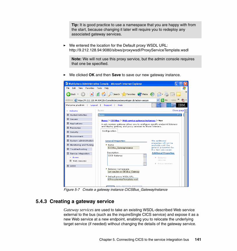
� We entered the location for the Default proxy WSDL URL: http://9.212.128.94:9080/sibws/proxywsdl/ProxyServiceTemplate.wsdl
� We clicked OK and then Save to save our new gateway instance.
Figure 5-7 Create a gateway instance CICSBus_GatewayInstance
5.4.3 Creating a gateway service
Gateway services are used to take an existing WSDL-described Web service external to the bus (such as the inquireSingle CICS service) and expose it as a new Web service at a new endpoint, enabling you to relocate the underlying target service (if needed) without changing the details of the gateway service.
Tip: It is good practice to use a namespace that you are happy with from the start, because changing it later will require you to redeploy any associated gateway services.
Note: We will not use this proxy service, but the admin console requires that one be specified.
Chapter 5. Connecting CICS to the service integration bus 141
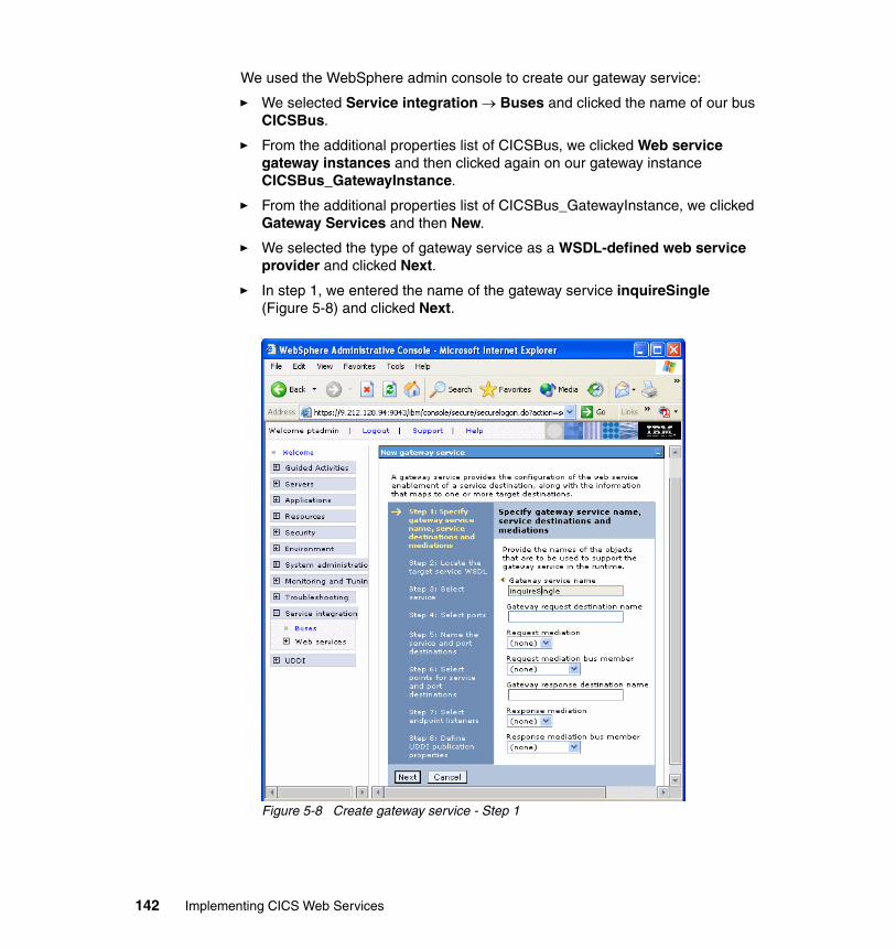
We used the WebSphere admin console to create our gateway service:
� We selected Service integration → Buses and clicked the name of our bus CICSBus.
� From the additional properties list of CICSBus, we clicked Web service gateway instances and then clicked again on our gateway instance CICSBus_GatewayInstance.
� From the additional properties list of CICSBus_GatewayInstance, we clicked Gateway Services and then New.
� We selected the type of gateway service as a WSDL-defined web service provider and clicked Next.
� In step 1, we entered the name of the gateway service inquireSingle (Figure 5-8) and clicked Next.
Figure 5-8 Create gateway service - Step 1
142 Implementing CICS Web Services
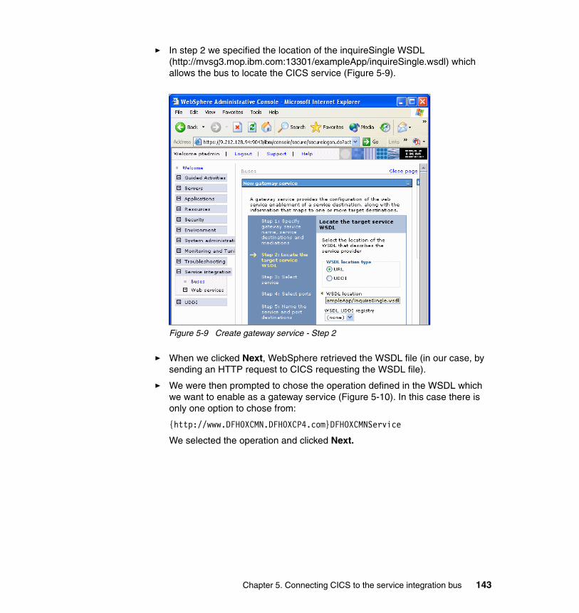
� In step 2 we specified the location of the inquireSingle WSDL (http://mvsg3.mop.ibm.com:13301/exampleApp/inquireSingle.wsdl) which allows the bus to locate the CICS service (Figure 5-9).
Figure 5-9 Create gateway service - Step 2
� When we clicked Next, WebSphere retrieved the WSDL file (in our case, by sending an HTTP request to CICS requesting the WSDL file).
� We were then prompted to chose the operation defined in the WSDL which we want to enable as a gateway service (Figure 5-10). In this case there is only one option to chose from:
{http://www.DFH0XCMN.DFH0XCP4.com}DFH0XCMNService
We selected the operation and clicked Next.
Chapter 5. Connecting CICS to the service integration bus 143

Figure 5-10 Create gateway service - Step 3
� For each of the steps 4 through 6 we accepted the default options.
� In step 7 (Select endpoint listeners), we selected the servernameSOAPHTTPChannel1 endpoint listener (the only one associated with our bus).
� For step 8 (Define UDDI publication properties), we accepted the default (no UDDI reference), clicked Finish and saved our changes.
We have now successfully defined our CICS gateway service (Figure 5-11).
Figure 5-11 inquireSingle gateway service
144 Implementing CICS Web Services
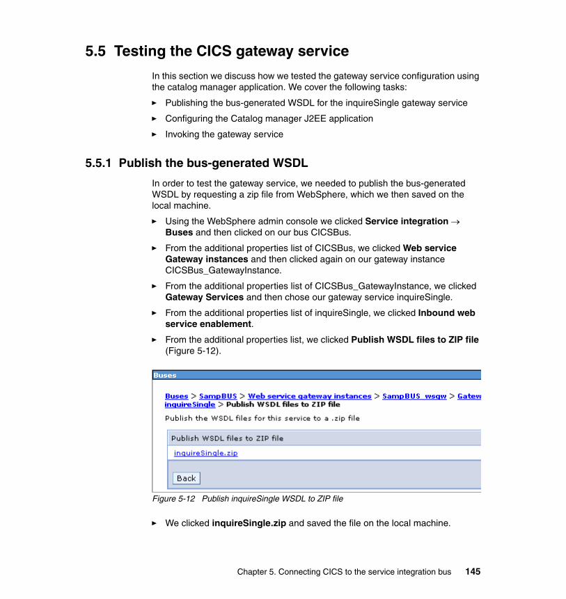
5.5 Testing the CICS gateway service
In this section we discuss how we tested the gateway service configuration using the catalog manager application. We cover the following tasks:
� Publishing the bus-generated WSDL for the inquireSingle gateway service
� Configuring the Catalog manager J2EE application
� Invoking the gateway service
5.5.1 Publish the bus-generated WSDL
In order to test the gateway service, we needed to publish the bus-generated WSDL by requesting a zip file from WebSphere, which we then saved on the local machine.
� Using the WebSphere admin console we clicked Service integration → Buses and then clicked on our bus CICSBus.
� From the additional properties list of CICSBus, we clicked Web service Gateway instances and then clicked again on our gateway instance CICSBus_GatewayInstance.
� From the additional properties list of CICSBus_GatewayInstance, we clicked Gateway Services and then chose our gateway service inquireSingle.
� From the additional properties list of inquireSingle, we clicked Inbound web service enablement.
� From the additional properties list, we clicked Publish WSDL files to ZIP file (Figure 5-12).
Figure 5-12 Publish inquireSingle WSDL to ZIP file
� We clicked inquireSingle.zip and saved the file on the local machine.
Chapter 5. Connecting CICS to the service integration bus 145
� We unzipped the file and noted that the following files were contained in the zip:
– CICSBus.inquireSingleBindings.wsdl– CICSBusinquireSingleNonBound.wsdl– CICSBus.inquireSinglePortTypes.wsdl– CICSBus.inquireSingleService.wsdl
� The endpoint information (for the inquireSingle gateway service) is stored in file CICSBus.inquireSingleService.wsdl. We opened the file and located the SOAP address in the service element (Example 5-2). This is the endpoint address for our gateway service.
Example 5-2 Gateway service inquireSingle endpoint address
<soap:address location="http://9.212.128.94:9080/wsgwsoaphttp1/soaphttpengine/CICSBus/inquireSingle/MVO6_server1_SOAPHTTPChannel1_InboundPort"/>
5.5.2 Configuring the catalog manager J2EE application
Next we needed to configure the catalog manager J2EE application so that it accesses the inquireSingle gateway service. We started a Web browser session and entered the URL:
http://cam21-pc11:9080/CatalogWeb/Welcome.jsp
We clicked CONFIGURE and specified the endpoint address of the inquireSingle gateway service for the Catalog manager Inquire Item Service Endpoint (Figure 5-13). We clicked SUBMIT to complete the update.
146 Implementing CICS Web Services
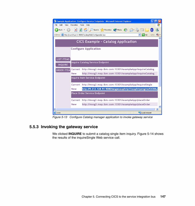
Figure 5-13 Configure Catalog manager application to invoke gateway service
5.5.3 Invoking the gateway service
We clicked INQUIRE to submit a catalog single item inquiry. Figure 5-14 shows the results of the inquireSingle Web service call.
Chapter 5. Connecting CICS to the service integration bus 147
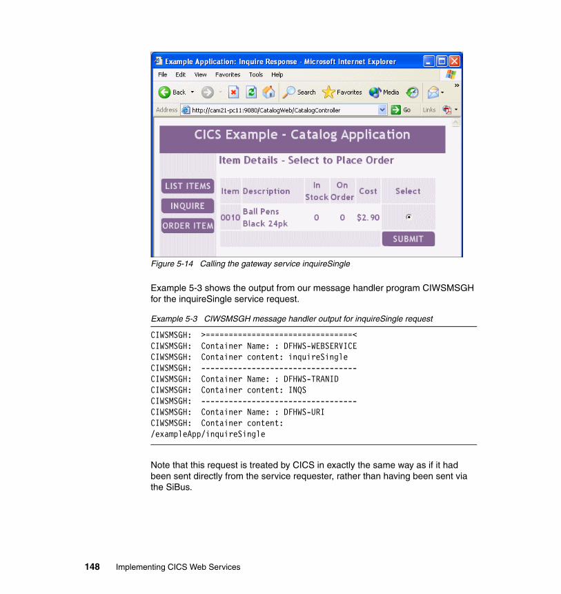
Figure 5-14 Calling the gateway service inquireSingle
Example 5-3 shows the output from our message handler program CIWSMSGH for the inquireSingle service request.
Example 5-3 CIWSMSGH message handler output for inquireSingle request
CIWSMSGH: >================================< CIWSMSGH: Container Name: : DFHWS-WEBSERVICE CIWSMSGH: Container content: inquireSingle CIWSMSGH: ---------------------------------- CIWSMSGH: Container Name: : DFHWS-TRANID CIWSMSGH: Container content: INQS CIWSMSGH: ---------------------------------- CIWSMSGH: Container Name: : DFHWS-URI CIWSMSGH: Container content: /exampleApp/inquireSingle
Note that this request is treated by CICS in exactly the same way as if it had been sent directly from the service requester, rather than having been sent via the SiBus.
148 Implementing CICS Web Services
Part 3 Security management
In this part, we provide an introduction to security technologies as they relate to securing CICS Web services and we then outline security scenarios that demonstrate how you can secure a CICS Web services environment.
Part 3
© Copyright IBM Corp. 2006. All rights reserved. 149

150 Implementing CICS Web Services
Chapter 6. Securing Web services
While you can exercise very strict control over the access to your applications via conventional 3270 terminals, your Web services clients are likely to be in remote locations, and you will be faced with new security issues.
When implementing a CICS Web services solution, you need to consider questions like the following:
� Will authentication be done by CICS itself or in an external server such as WebSphere Application Server?
� What authorization mechanisms will be used to protect access to the CICS system and access to resources such as transactions, files, and databases?
� How will you protect the confidentiality of data that is transported between the different tiers of the physical configuration?
In this chapter, we provide an introduction to security technologies as they relate to securing CICS Web services.
6
© Copyright IBM Corp. 2006. All rights reserved. 151
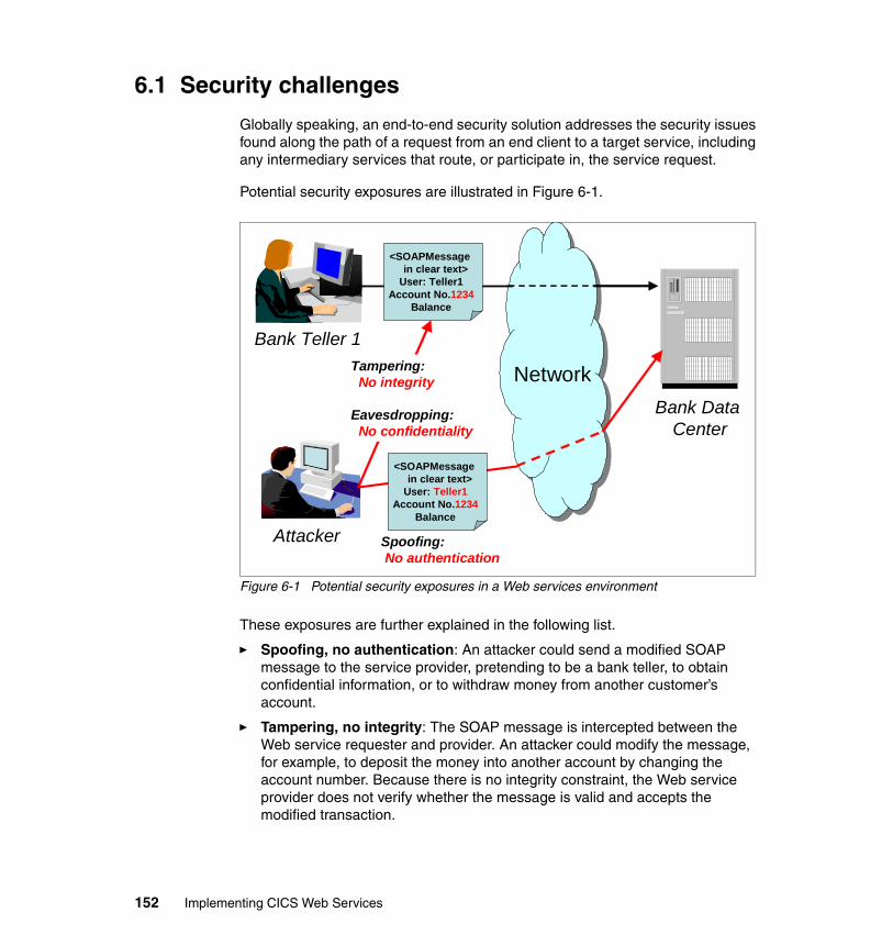
6.1 Security challenges
Globally speaking, an end-to-end security solution addresses the security issues found along the path of a request from an end client to a target service, including any intermediary services that route, or participate in, the service request.
Potential security exposures are illustrated in Figure 6-1.
Figure 6-1 Potential security exposures in a Web services environment
These exposures are further explained in the following list.
� Spoofing, no authentication: An attacker could send a modified SOAP message to the service provider, pretending to be a bank teller, to obtain confidential information, or to withdraw money from another customer’s account.
� Tampering, no integrity: The SOAP message is intercepted between the Web service requester and provider. An attacker could modify the message, for example, to deposit the money into another account by changing the account number. Because there is no integrity constraint, the Web service provider does not verify whether the message is valid and accepts the modified transaction.
<SOAPMessagein clear text>
User: Teller1Account No.1234
Balance
<SOAPMessagein clear text>
User: Teller1Account No.1234
Balance
Network
Bank Teller 1
Attacker
Bank Data Center
Spoofing:No authentication
Tampering:No integrity
Eavesdropping:No confidentiality
152 Implementing CICS Web Services
� Eavesdropping, no confidentiality: Without data encryption, SOAP messages are sent in clear text, and the information contained in the message can be intercepted or read by an attacker. Confidential customer or bank information can get into the wrong hands.
In order to protect against the risk of these security exposures, you can use a combination of two types of security to secure your Web services environment:
� Transport-level security
Transport-level security mechanisms such as HTTPS can be used to secure Web services. In “Transport security” on page 157 we review how different transport-level security mechanisms can be used to secure a CICS Web services solution.
� SOAP message security
The Web services security model introduces a set of individual interrelated specifications to form a layering approach to security. It includes several aspects of security: identification, authentication, authorization, integrity, confidentiality, auditing, and non-repudiation. When using these specifications, security information is transported within the SOAP message itself as SOAP security headers.The WS-Security specification is co-developed by IBM, Microsoft, and VeriSign. At the time of writing this redbook, WS-Security support is not provided directly by CICS. This means that CICS itself does not process security data which is contained within SOAP security headers. However, it is possible to write a SOAP header processing program, which can be used as part of a CICS pipeline, to process SOAP security headers. This is explained in detail in “Enabling SOAP message security with HTTP” on page 187.
6.1.1 The meaning of security
Security is implemented when mechanisms have been put in place to achieve the following objectives.
� Identification: This is the ability to assign an identity to the entity accessing the system. Typically the identity is used to control access to resources. From a conceptual standpoint, a system can be accessed without an identity, in an anonymous way. From a practical standpoint, anonymous access results in the execution of a request under a generic identity with low privileges. Depending on the security model in which the identification is performed, the identity can be termed as a user ID or a UID, or in the Java 2 Platform, Enterprise Edition (J2EE) security model, it can be referred to as a principal.
� Authentication: This is the process of validating the identity claimed by the accessing entity. Authentication is needed when access discrimination is required on the basis of requesting identities. Authentication is performed by
Chapter 6. Securing Web services 153
verifying authentication information provided with the claimed identity. The authentication information is generally referred to as credentials. A credential can be the accessor’s name and password; it can also be a token provided by a trusted party, such as a Kerberos ticket or an X.509 certificate.
� Authorization: This is the process of checking whether an asserted (already authenticated) identity has access to a requested resource. A typical implementation of authorization is to pass, to the access control mechanism, an execution security context that contains the asserted identity.
� Integrity: Integrity ensures that transmitted or stored information has not been altered in an unauthorized or accidental manner. Typically it is a mechanism to verify that what is received over a network is the same as what was sent.
� Confidentiality: This refers to the concept that an unauthorized party cannot obtain the meaning of the transferred or stored data. Typically confidentiality is achieved by encrypting the data.
� Auditing: With auditing, you capture and record security-related events, so that they can be exposed and analyzed after the fact.
� Non-repudiation: Both parties are able to provide legal proof to a third party that the sender did send the information, and the receiver received the identical information. Neither side is able to deny.
The role of cryptographyCryptography is required to thoroughly achieve authentication, data integrity, confidentiality, and non-repudiation. Three kinds of algorithms are most commonly used for these purposes.
� Public key, or asymmetric, algorithms (typically the RSA algorithm)
These algorithms use a pair of keys. What has been encrypted with one key of the pair can only be decrypted with the other key of the pair. One key is kept secret; this is the private key. The other key is the public key, and as the name implies, its value is public knowledge. Public key algorithms can be used to achieve authentication.
Note: Authentication is usually one of the earliest steps in a request workflow. When authenticated, an identity can be asserted to the downstream process steps, meaning that these steps trust the upstream steps to have already successfully authenticated the identity.
Note: RSA is a method of public key encryption developed by Rivest, Shamir, and Adelman at the Massachusetts Institute of Technology (MIT).
154 Implementing CICS Web Services
� Shared secret key, or symmetric, algorithms (typically the Data Encryption Standard (DES) algorithm)
The same single secret key is used both for encryption and decryption. Shared secret key algorithms are used for data confidentiality.
� One-way algorithm
This algorithm condenses an input string to a short fixed length numeric value called the hash. Typically a hash is a 128-bit or 160-bit value. Any change in the input string induces a change in the hash value. The Secure Hash Algorithm (SHA-1) is such an algorithm. Its output is used as a fingerprint for the contents of a message.
6.2 Traditional CICS security
In a CICS environment, the assets you normally want to protect are the application programs and the resources that are accessed by the application programs. To prevent disclosure, destruction, or corruption of these assets, you must control access to the CICS region and to different CICS components.
You can limit the activities of a CICS user to only those functions that the user is authorized to use by implementing one or more of the following CICS security mechanisms:
� Transaction security
This ensures that users who attempt to run a transaction are entitled to do so.
� Resource security
This ensures that users who use CICS resources, such as files and transient data queues, are entitled to do so.
� Command security
This ensures that users who use CICS system programming commands are entitled to do so.
� Surrogate security
This ensures that a surrogate user is authorized to act on behalf of another user.
When CICS security is active, requests to attach transactions, and requests by transactions to access resources, are associated with a user ID. When a user makes a request, CICS calls the external security manager (such as RACF®) to determine if the user ID has the authority to make the request. If the user ID does not have the correct authority, CICS denies the request.
Chapter 6. Securing Web services 155
In many cases, a user is a human operator, interacting with CICS through a terminal or a workstation. However, the user can also be a Web browser user or, in a Web services solution, a program executing in a client system.
For a complete discussion of CICS security, refer to CICS TS V3.1 RACF Security Guide, SC34-6249.
6.2.1 CICS user IDs
When a human operator signs on to a CICS region at the start of a terminal session, he or she is challenged to provide a user ID and password. The user ID remains associated with the terminal until the terminal operator signs off. Transactions executed from the terminal, and requests made by those transactions, are associated with that user ID.
For connections from Web users, there are other ways that the user of a CICS transaction can be identified, including:
� A Web browser user is challenged to provide HTTP basic authentication information (a user ID and password). The transaction that services the client’s request, and further requests made by that transaction, are associated with that user ID.
� A client program that is communicating with CICS using the Secure Sockets Layer (SSL) supplies a client certificate to identify itself. The security manager maps the certificate to a user ID. The transaction that services the client’s request, and further requests made by that transaction, are associated with that user ID.
In addition to these transport-level authentication mechanisms, Web service clients may also pass authentication data in the SOAP message. We cover transport-level security in more detail in “Transport security” on page 157 and the different ways of passing authentication data in SOAP messages in “SOAP message security” on page 164.
CICS special user IDsThere are two particular user IDs that CICS uses in addition to those that identify individual end users. These are:
Region user ID The CICS region user ID is used for authorization checking when the CICS system (rather than an individual user of the system) requests access to system resources such as CICS data sets and other servers.
Default user ID When a user does not sign on, CICS assigns a default user ID to the user. It is specified in the SIT parameter DFLTUSER. In the absence of more explicit identification, it
156 Implementing CICS Web Services
is used to identify TCP/IP clients that connect to CICS. You should give very little authority to the default user ID.
6.3 Transport security
Web services messaging relies on two protocol layers: the transport layer and the SOAP layer. Security can be implemented within either, or both, of these layers.
In this section we review how the different transport-level security mechanisms can be used to secure a CICS Web services solution. In “Comparison of transport versus SOAP message security” on page 172 we look at the main decision factors for choosing between transport-level and SOAP message security.
6.3.1 HTTP transport
When a CICS Web service is invoked using HTTP, standard HTTP security mechanisms can be used to authenticate the Web service client and to ensure message integrity and confidentiality.
Basic authenticationHTTP basic authentication is a simple challenge and response mechanism with which a server can request authentication information (a user ID and password) from a client. The client passes the authentication information to the server in an HTTP Authorization header. The authentication information is in base-64 encoding.
The AUTHENTICATE attribute on the CICS TCPIPSERVICE resource definition specifies the authentication and identification scheme to be used for inbound TCP/IP connections for the HTTP protocol. HTTP basic authentication is enabled with CICS by specifying BASIC for the AUTHENTICATE attribute.
A CICS service provider application can be protected by HTTP basic authentication. However, the HTTP basic authentication scheme can only be considered a secure means of authentication when the connection between the Web service client and the CICS region is secure. If the connection is insecure, the scheme does not provide sufficient security to prevent unauthorized users from discovering and using the authentication information for a server. If there is a possibility of a password being intercepted, basic authentication should be used in combination with SSL, so that SSL encryption is used to protect the user ID and password information.
Chapter 6. Securing Web services 157
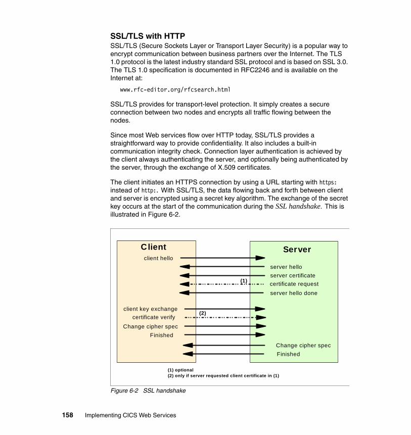
SSL/TLS with HTTPSSL/TLS (Secure Sockets Layer or Transport Layer Security) is a popular way to encrypt communication between business partners over the Internet. The TLS 1.0 protocol is the latest industry standard SSL protocol and is based on SSL 3.0. The TLS 1.0 specification is documented in RFC2246 and is available on the Internet at:
www.rfc-editor.org/rfcsearch.html
SSL/TLS provides for transport-level protection. It simply creates a secure connection between two nodes and encrypts all traffic flowing between the nodes.
Since most Web services flow over HTTP today, SSL/TLS provides a straightforward way to provide confidentiality. It also includes a built-in communication integrity check. Connection layer authentication is achieved by the client always authenticating the server, and optionally being authenticated by the server, through the exchange of X.509 certificates.
The client initiates an HTTPS connection by using a URL starting with https: instead of http:. With SSL/TLS, the data flowing back and forth between client and server is encrypted using a secret key algorithm. The exchange of the secret key occurs at the start of the communication during the SSL handshake. This is illustrated in Figure 6-2.
Figure 6-2 SSL handshake
Clientclient hello
server hello
client key exchange
server certificate
Server
server hello done
Change cipher specFinished
Change cipher specFinished
certificate request
certificate verify
(1)
(2)
(1) optional(2) only if server requested client certificate in (1)
158 Implementing CICS Web Services
The server’s certificate contains the server’s public key. The client uses this public key to encrypt an initial value for a secret key to be sent to the server. Once both client and server have obtained the same secret key value, the handshake ends, and they will change their encryption algorithm to the new and less CPU-intensive secret key procedure. The server can also request a digital certificate from the client, to verify its identity.
CICS support for SSL/TLSCICS supports both the SSL 3.0 and TLS 1.0 protocols. HTTPS connections will automatically use the TLS protocol, unless the client specifically requires SSL 3.0.
A CICS service provider application can be secured using HTTPS. HTTPS has the following advantages:
� It can be used to provide a very fast and secure transport for CICS Web services.
� It provides for authentication through either HTTP basic authentication or a client X.509 certificate.
� It provides integrity between the service requester and CICS by using asymmetric key cryptography to establish authenticity of server and client, and to securely share a secret key.
� It provides confidentiality between the service requester and CICS through efficient shared key cryptography.
� It can be used with hardware cryptographic devices that can significantly reduce the cost of SSL handshakes. You can customize your encryption settings to use only the cipher suites that use the Integrated Cryptographic Facility (ICSF), such as the DES and SHA-1 cipher suites.
� It is mature and similarly implemented by most vendors, and therefore, is subject to few interoperability problems.
A CICS service requester application can also use HTTPS to invoke a service provider application, with similar advantages to those listed.
Enabling CICS support for SSL/TLSTo activate SSL/TLS support in a CICS TS V3.1 region, you must specify values for the following system initialization parameters:
� ENCRYPTION={STRONG | WEAK | MEDIUM}
Specifies the cipher suites that CICS uses for secure TCP/IP connections. When a secure connection is established between the client and CICS, the most secure cipher suite supported by both is used.
Chapter 6. Securing Web services 159
– Use ENCRYPTION=STRONG when you can tolerate the overhead of using high encryption if the other system requires it.
– Use ENCRYPTION=WEAK when you want to use encryption keys up to 40 bits in length.
– Use ENCRYPTION=MEDIUM when you want to use encryption keys up to 56 bits in length.
For more information about cipher suites, see the CICS TS V3.1 RACF Security Guide, SC34-6249.
� KEYRING=key-database-pathname
Specifies the name of a key ring in the RACF database that contains keys and certificates used by CICS. It must be owned by the CICS region userid. You can create an initial key ring with the DFH$RING exec in the CICS-supplied SDFHSAMP target library.
� MAXSSLTCBS={8 | number}
Specifies the maximum number of S8 TCBs that are available to CICS to process secure sockets layer connections. The S8 TCBs are created and managed in the SSL pool. An S8 TCB is only used by a task for the duration of the SSL processing.
The maximum number of S8 TCBs that you can set is 1024. Increasing the number of available TCBs allows more simultaneous SSL connections to take place. However, increasing the number of TCBs too much will impact storage below the line.
� SSLDELAY={600 | number}
Specifies the length of time in seconds for which CICS retains session IDs for secure socket connections in the SSLCACHE. Session IDs are tokens that represent a secure connection between CICS and an SSL client. The session ID is created and exchanged between the SSL client and CICS during the SSL handshake.
While the session ID is retained by CICS within the SSLDELAY period, CICS will re-establish an SSL connection with a client without the significant overhead of another SSL handshake. The value is a number of seconds in the range 0 through 86400. The default value is 600.
Increasing the value of the SSLDELAY parameter retains the session IDs in the cache for longer, thereby optimizing the time it takes to perform SSL negotiations.
� SSLCACHE={CICS | SYSPLEX}
Specifies whether CICS should use the local SSL cache in the CICS region, or share the cache across multiple CICS regions by using the coupling facility.
160 Implementing CICS Web Services
If the cache is shared between a number of CICS regions, the throughput of SSL connections will improve.
Caching across a sysplex can only take place when the regions accept SSL connections at the same IP address.
In “Enabling SSL/TLS” on page 203 we show how we enabled our CICS region to support SSL connections from our Web service client running in WebSphere Application Server.
Activating SSL for a TCPIPSERVICETo activate SSL support for a given connection, you must set the value of the SSL attribute on the connection’s TCPIPSERVICE definition to one of the following:
� YESIf you set the value to YES, CICS will send a server certificate to the client.
� CLIENTAUTHIf you set the value to CLIENTAUTH, CICS will send a server certificate to the client and the client must send a client certificate to CICS.
If you specify SSL(CLIENTAUTH) you can also specify AUTHENTICATE(CERTIFICATE) in order to map the client certificate to a RACF user ID, which is then used as the identity for the client.
Setting the user ID on the URIMAPIt is possible to specify a user ID on the URIMAP to be used on behalf of a Web service client. This is done by setting the USERID attribute of the URIMAP definition for a request. It specifies the 1 to 8 character user ID under which the Web services pipeline alias transaction is attached.
A user ID that you specify in the URIMAP definition is overridden by any user ID that is obtained directly from the client.
Note: If you define and install URIMAP resource definitions explicitly using CEDA, and you are using the CICS Web services assistant to create the Web services, you cannot take advantage of the dynamic installation of URIMAP resources when the PIPELINE resource is installed.
Important: If you use a URIMAP definition to set a user ID, there is no authentication of the client’s identity. You should only do this when communicating with your own client system, which has already authenticated its users, and communicates with the server in a secure environment.
Chapter 6. Securing Web services 161
Determining the user ID order of precedence when using HTTPIt is possible that for a single Web service request transported by HTTP, multiple methods for setting the user ID will be used at the same time. In this event, the following order of precedence is used for setting the user ID under which the target business logic program runs:
1. A user ID specified by a message handler, or a SOAP header processing program, that is included in the pipeline that processes the SOAP message. For example, a SOAP header processing program could extract a username from the SOAP message and specify that the CICS task should run with this user ID. See “SOAP message security” on page 164 for more information on how SOAP message security can be used with CICS and HTTP.
2. A user ID obtained from the Web client using basic authentication, or a user ID associated with a client certificate.
3. A user ID specified in the URIMAP definition for the request.
4. The CICS default user ID, if no other can be determined.
6.3.2 WebSphere MQ Security
To control security checking performed by WebSphere MQ (WMQ), you must define switch profiles. When a queue manager is started (or when the WMQ REFRESH SECURITY command is issued), WMQ first checks the status of RACF and the MQADMIN class. It sets the subsystem security switch off if it discovers one of these conditions:
� RACF is inactive or not installed.
� The MQADMIN class is not defined.
� The MQADMIN class has not been activated.
If both RACF and the MQADMIN class are active, WMQ checks the MQADMIN class to see whether any of the switch profiles have been defined. If subsystem security is not required, WMQ sets the internal subsystem security switch off, and performs no further checks. The sequence of subsystem security checks is shown in Figure 6-3.
162 Implementing CICS Web Services
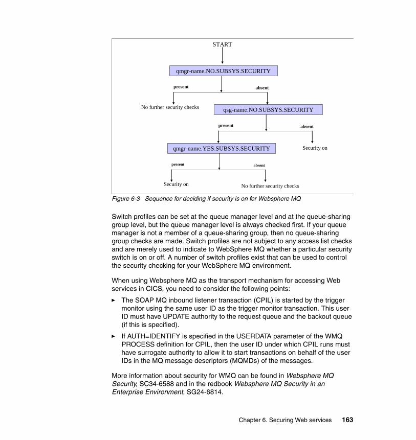
Figure 6-3 Sequence for deciding if security is on for Websphere MQ
Switch profiles can be set at the queue manager level and at the queue-sharing group level, but the queue manager level is always checked first. If your queue manager is not a member of a queue-sharing group, then no queue-sharing group checks are made. Switch profiles are not subject to any access list checks and are merely used to indicate to WebSphere MQ whether a particular security switch is on or off. A number of switch profiles exist that can be used to control the security checking for your WebSphere MQ environment.
When using Websphere MQ as the transport mechanism for accessing Web services in CICS, you need to consider the following points:
� The SOAP MQ inbound listener transaction (CPIL) is started by the trigger monitor using the same user ID as the trigger monitor transaction. This user ID must have UPDATE authority to the request queue and the backout queue (if this is specified).
� If AUTH=IDENTIFY is specified in the USERDATA parameter of the WMQ PROCESS definition for CPIL, then the user ID under which CPIL runs must have surrogate authority to allow it to start transactions on behalf of the user IDs in the MQ message descriptors (MQMDs) of the messages.
More information about security for WMQ can be found in Websphere MQ Security, SC34-6588 and in the redbook Websphere MQ Security in an Enterprise Environment, SG24-6814.
START
No further security checks
qmgr-name.YES.SUBSYS.SECURITY
Security on
present absent
qsg-name.NO.SUBSYS.SECURITY
present absent
Security on
qmgr-name.NO.SUBSYS.SECURITY
present absent
No further security checks
Chapter 6. Securing Web services 163
SSL/TLS with WebSphere MQ
SSL/TLS can be used to secure SOAP messages that are transported using WMQ. WMQ supports Version 3.0 of the SSL protocol. You specify the cryptographic algorithms that are used by the SSL protocol by supplying a CipherSpec as part of the channel definition. WMQ also supports Version 1.0 of the Transport Layer Security (TLS) protocol.
See WebSphere MQ Security, SC34-6588 for more information on using SSL/TLS with WMQ.
Determining the user ID order of precedence when using WMQIt is possible that for a single Web service request transported by WMQ, multiple methods for setting the user ID will be used at the same time. In this event, the following order of precedence is used for setting the user ID under which the target business logic program runs:
1. A user ID specified by a message handler, or a SOAP header processing program, that is included in the pipeline that processes the SOAP message. For example, a SOAP header processing program could extract a username from the SOAP message and specify that the CICS task should run with this user ID. See “Enabling SOAP message security with WMQ” on page 214 for more information on how SOAP message security can be used with CICS and WMQ.
2. A user ID obtained from the MQ message descriptor.
A message can contain message context information, such as a user ID. This information is held in the message descriptor and can be generated by the queue manager when a message is put on a queue by an application, or by the application itself. This allows the receiving application to run with the same identity as the application that put the message on the queue.
3. The CICS default user ID, if no other can be determined.
6.4 SOAP message security
The first version of the WS-Security specification was proposed by IBM, Microsoft, and VeriSign in April 2002. After the formalization of the April 2002 specification, the specification was transferred to the OASIS consortium:
http://www.oasis-open.org
Note: We found that although URIMAP resources are required for service providers using WMQ, the USERID and TRANSACTION attributes were ignored.
164 Implementing CICS Web Services
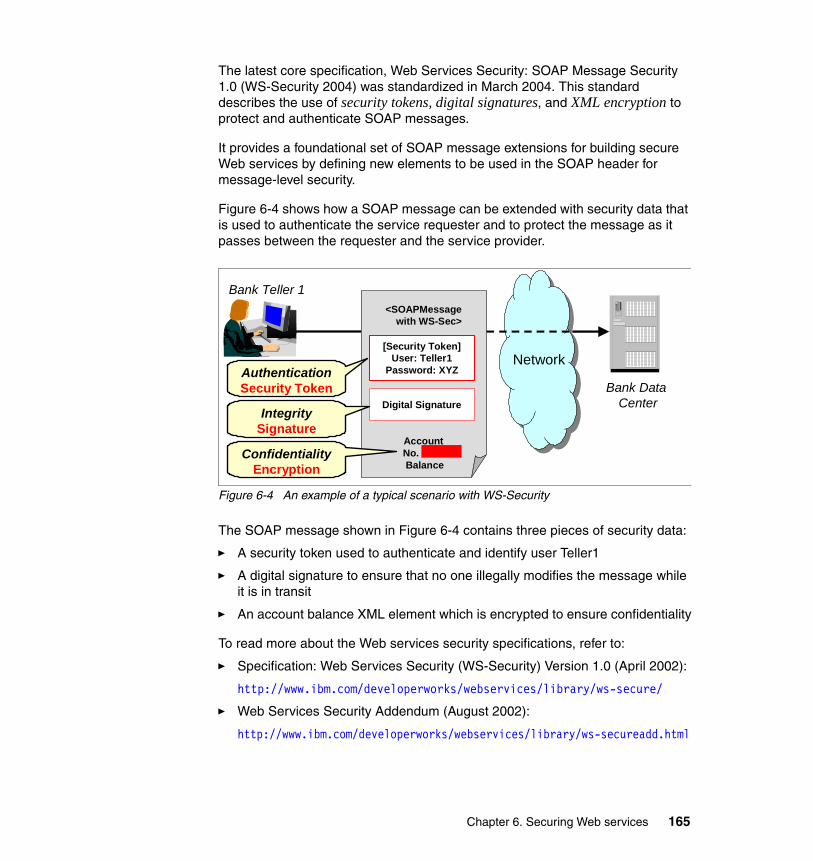
The latest core specification, Web Services Security: SOAP Message Security 1.0 (WS-Security 2004) was standardized in March 2004. This standard describes the use of security tokens, digital signatures, and XML encryption to protect and authenticate SOAP messages.
It provides a foundational set of SOAP message extensions for building secure Web services by defining new elements to be used in the SOAP header for message-level security.
Figure 6-4 shows how a SOAP message can be extended with security data that is used to authenticate the service requester and to protect the message as it passes between the requester and the service provider.
Figure 6-4 An example of a typical scenario with WS-Security
The SOAP message shown in Figure 6-4 contains three pieces of security data:
� A security token used to authenticate and identify user Teller1
� A digital signature to ensure that no one illegally modifies the message while it is in transit
� An account balance XML element which is encrypted to ensure confidentiality
To read more about the Web services security specifications, refer to:
� Specification: Web Services Security (WS-Security) Version 1.0 (April 2002):
http://www.ibm.com/developerworks/webservices/library/ws-secure/
� Web Services Security Addendum (August 2002):
http://www.ibm.com/developerworks/webservices/library/ws-secureadd.html
<SOAPMessagewith WS-Sec>
Account No.Balance
Network
Bank Teller 1
Bank Data Center
[Security Token]User: Teller1
Password: XYZ
Digital Signature
AuthenticationSecurity Token
IntegritySignature
ConfidentialityEncryption
Chapter 6. Securing Web services 165
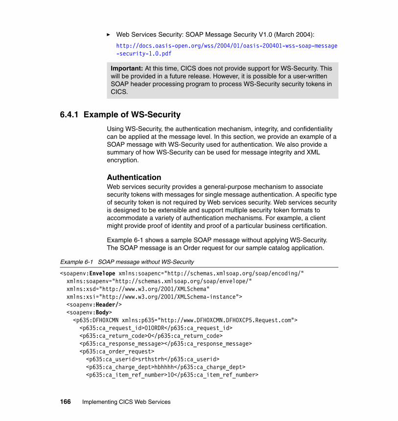
� Web Services Security: SOAP Message Security V1.0 (March 2004):
http://docs.oasis-open.org/wss/2004/01/oasis-200401-wss-soap-message-security-1.0.pdf
6.4.1 Example of WS-Security
Using WS-Security, the authentication mechanism, integrity, and confidentiality can be applied at the message level. In this section, we provide an example of a SOAP message with WS-Security used for authentication. We also provide a summary of how WS-Security can be used for message integrity and XML encryption.
AuthenticationWeb services security provides a general-purpose mechanism to associate security tokens with messages for single message authentication. A specific type of security token is not required by Web services security. Web services security is designed to be extensible and support multiple security token formats to accommodate a variety of authentication mechanisms. For example, a client might provide proof of identity and proof of a particular business certification.
Example 6-1 shows a sample SOAP message without applying WS-Security. The SOAP message is an Order request for our sample catalog application.
Example 6-1 SOAP message without WS-Security
<soapenv:Envelope xmlns:soapenc="http://schemas.xmlsoap.org/soap/encoding/" xmlns:soapenv="http://schemas.xmlsoap.org/soap/envelope/" xmlns:xsd="http://www.w3.org/2001/XMLSchema" xmlns:xsi="http://www.w3.org/2001/XMLSchema-instance"><soapenv:Header/><soapenv:Body>
<p635:DFH0XCMN xmlns:p635="http://www.DFH0XCMN.DFH0XCP5.Request.com"> <p635:ca_request_id>01ORDR</p635:ca_request_id> <p635:ca_return_code>0</p635:ca_return_code> <p635:ca_response_message></p635:ca_response_message>
<p635:ca_order_request> <p635:ca_userid>srthstrh</p635:ca_userid> <p635:ca_charge_dept>hbhhhh</p635:ca_charge_dept> <p635:ca_item_ref_number>10</p635:ca_item_ref_number>
Important: At this time, CICS does not provide support for WS-Security. This will be provided in a future release. However, it is possible for a user-written SOAP header processing program to process WS-Security security tokens in CICS.
166 Implementing CICS Web Services
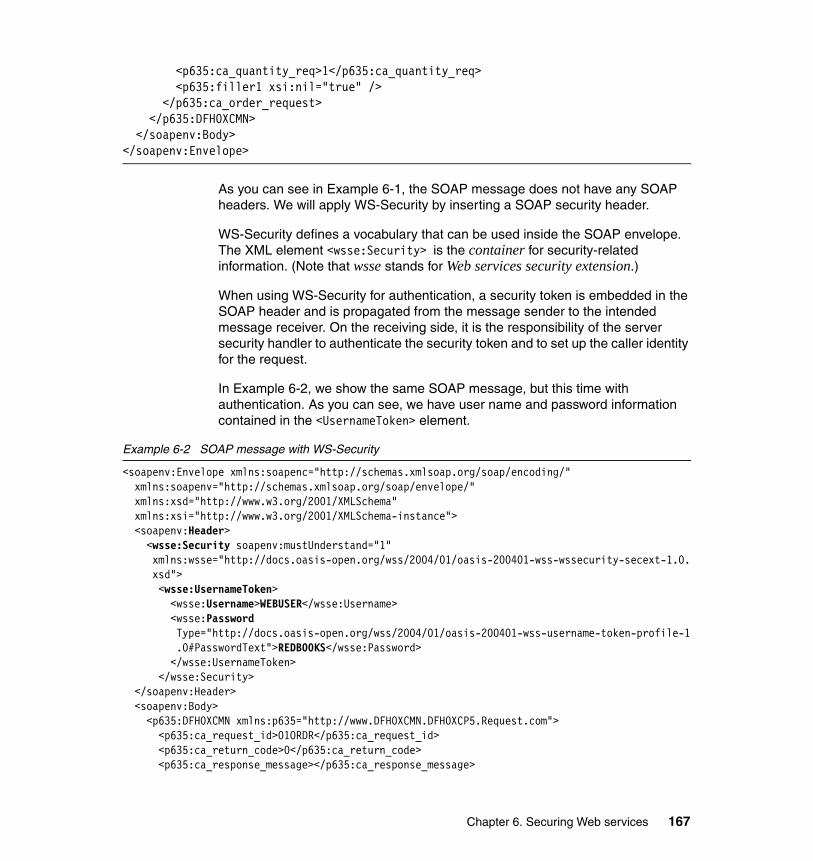
<p635:ca_quantity_req>1</p635:ca_quantity_req> <p635:filler1 xsi:nil="true" /> </p635:ca_order_request>
</p635:DFH0XCMN> </soapenv:Body></soapenv:Envelope>
As you can see in Example 6-1, the SOAP message does not have any SOAP headers. We will apply WS-Security by inserting a SOAP security header.
WS-Security defines a vocabulary that can be used inside the SOAP envelope. The XML element <wsse:Security> is the container for security-related information. (Note that wsse stands for Web services security extension.)
When using WS-Security for authentication, a security token is embedded in the SOAP header and is propagated from the message sender to the intended message receiver. On the receiving side, it is the responsibility of the server security handler to authenticate the security token and to set up the caller identity for the request.
In Example 6-2, we show the same SOAP message, but this time with authentication. As you can see, we have user name and password information contained in the <UsernameToken> element.
Example 6-2 SOAP message with WS-Security
<soapenv:Envelope xmlns:soapenc="http://schemas.xmlsoap.org/soap/encoding/" xmlns:soapenv="http://schemas.xmlsoap.org/soap/envelope/" xmlns:xsd="http://www.w3.org/2001/XMLSchema" xmlns:xsi="http://www.w3.org/2001/XMLSchema-instance"><soapenv:Header><wsse:Security soapenv:mustUnderstand="1" xmlns:wsse="http://docs.oasis-open.org/wss/2004/01/oasis-200401-wss-wssecurity-secext-1.0.xsd"><wsse:UsernameToken>
<wsse:Username>WEBUSER</wsse:Username> <wsse:Password
Type="http://docs.oasis-open.org/wss/2004/01/oasis-200401-wss-username-token-profile-1.0#PasswordText">REDB00KS</wsse:Password>
</wsse:UsernameToken> </wsse:Security> </soapenv:Header><soapenv:Body><p635:DFH0XCMN xmlns:p635="http://www.DFH0XCMN.DFH0XCP5.Request.com">
<p635:ca_request_id>01ORDR</p635:ca_request_id> <p635:ca_return_code>0</p635:ca_return_code> <p635:ca_response_message></p635:ca_response_message>
Chapter 6. Securing Web services 167
<p635:ca_order_request> <p635:ca_userid>srthstrh</p635:ca_userid> <p635:ca_charge_dept>hbhhhh</p635:ca_charge_dept> <p635:ca_item_ref_number>10</p635:ca_item_ref_number> <p635:ca_quantity_req>1</p635:ca_quantity_req> <p635:filler1 xsi:nil="true" /> </p635:ca_order_request>
</p635:DFH0XCMN> </soapenv:Body></soapenv:Envelope>
The <UsernameToken> element of the SOAP message in Example 6-2 contains credentials which can be used to authenticate the user WEBUSER.
The simplest form of security token is the UsernameToken, which is used to provide a user name and password for basic authentication. In “The WS-Security header processing program” on page 197, we show an example of how a header processing program can extract a UsernameToken from a SOAP header, validate the username and password, and set the user ID of the CICS task to the username passed in the header.
A signed security token is one that is cryptographically signed by a specific authority. For example, an X.509 certificate is a signed security token.
Security token usage for Web services security is defined in separate profiles such as the Username token profile and the X.509 token profile.
To read more about these security token standards, refer to:
� Web Services Security: UsernameToken Profile V1.0 (March 2004):
http://docs.oasis-open.org/wss/2004/01/oasis-200401-wss-username-token-profile-1.0.pdf
� Web Services Security: X.509 Token Profile V1.0 (March 2004):
http://docs.oasis-open.org/wss/2004/01/oasis-200401-wss-x509-token-profile-1.0.pdf
IntegrityIntegrity is applied to a message to ensure that no one modifies the message while it is in transit. Essentially, integrity is provided by generating an XML digital signature on a part of the SOAP message. If the message data changes, the signature would no longer be valid.
168 Implementing CICS Web Services
A digital signature is a number attached to the message. This signature establishes the following information:
� The integrity of the message:
Is the message intact? That is, has the message been modified between the time it was digitally signed and now?
� The identity of the signer of the message:
Is the message authentic? That is, was the message actually signed by the user who claims to have signed it?
A digital signature is created in two steps.
1. The first step distills a part of the SOAP message (for example, the body) into a large number. This number is the digest code or fingerprint. Several options are available for generating the digest code, for example, the MD5 message digest function and the SHA1 secure hash algorithm. Both these procedures reduce a message to a number.
The crucial aspect of distilling the document to a number is that if the message changes, even in a trivial way, a different digest code results. When the recipient gets a message and verifies the digest code by recomputing it, any changes in the document result in a mismatch between the stated and the computed digest codes.
2. In the second step, the digest code is encrypted with the sender's private key.
This two step process creates the digital signature. The digital signature is appended to the SOAP message before being sent to the service provider.
When the service provider receives the message, it performs three steps to verify the signature. The service provider:
1. Recomputes the digest code for the message.
2. Decrypts the signature by using the sender's public key. This decryption yields the original digest code for the message.
The receiver normally obtains the sender’s public key from the sender’s X.509 certificate, which is sent as a security token in the SOAP message.
3. Compares the original and recomputed digest codes. If these codes match, the message is both intact and authentic. If not, something has changed and the message is not to be trusted.
Important: The use of digital signatures has a significant impact on the system central processing unit (CPU) resource usage.
Chapter 6. Securing Web services 169
XML encryptionConfidentiality is the process in which a SOAP message is protected so that only authorized recipients can read the SOAP message. Confidentiality is provided by encrypting the contents of the SOAP message using XML encryption. If the SOAP message is encrypted, only a service that knows the key for confidentiality can decrypt and read the message.
The XML encryption standard specifies a process for encrypting data and representing the result in XML. XML encryption can be used to encrypt any part of a SOAP message, normally sensitive data such as bank account numbers or user credentials. The result of encrypting data is an XML encryption element that contains or references the cipher data.
XML-Encryption was published as a W3C recommendation in December 2002. More information can be found at:
http://www.w3.org/Encryption/2001/
WebSphere and SOAP message securitySupport for the WS-Security April 2002 draft specification is provided in WebSphere Application Server Versions 5.0.2 and 5.1. WebSphere Application Server Version 6.0 supports the WS-Security 2004 specification and two token profiles:
� UsernameToken 1.0
� X.509 Certificate Token 1.0
WebSphere Application Server V6 provides some types of security tokens as the default, and you can also implement custom tokens. The provided default types of tokens are:
� Username token, with username and password
� Binary security token, including X.509 certificate and LTPA (Lightweight Third party Authentication) token
WebSphere Application Server V6 uses the J2EE 1.4 Web services deployment model to implement WS-Security. The Web services security constraints are specified in the IBM extension of the Web services deployment descriptors and bindings. The Web services security run time enforces the security constraints specified in the deployment descriptors. One of the advantages of this deployment model is that you can define the Web services security requirements outside of the application business logic. With the separation of roles, the application developer can focus on the business logic and the security expert can specify the security requirement.
170 Implementing CICS Web Services
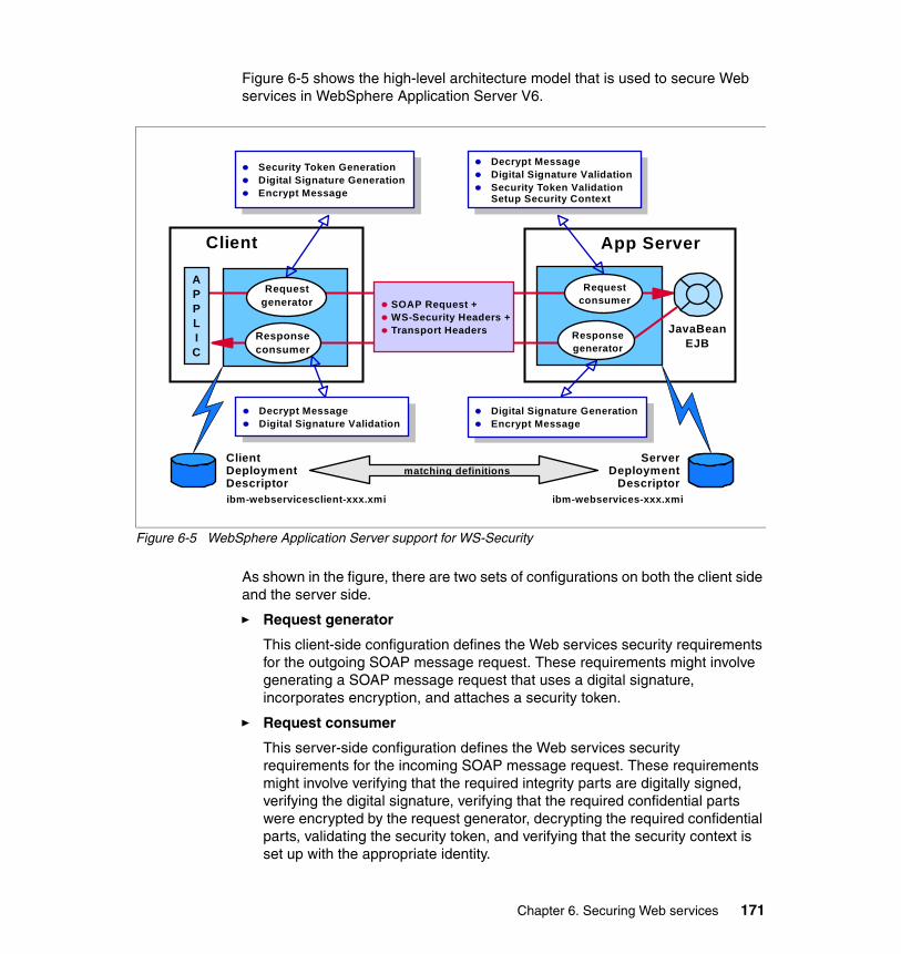
Figure 6-5 shows the high-level architecture model that is used to secure Web services in WebSphere Application Server V6.
Figure 6-5 WebSphere Application Server support for WS-Security
As shown in the figure, there are two sets of configurations on both the client side and the server side.
� Request generator
This client-side configuration defines the Web services security requirements for the outgoing SOAP message request. These requirements might involve generating a SOAP message request that uses a digital signature, incorporates encryption, and attaches a security token.
� Request consumer
This server-side configuration defines the Web services security requirements for the incoming SOAP message request. These requirements might involve verifying that the required integrity parts are digitally signed, verifying the digital signature, verifying that the required confidential parts were encrypted by the request generator, decrypting the required confidential parts, validating the security token, and verifying that the security context is set up with the appropriate identity.
JavaBeanEJB
ClientDeploymentDescriptor
ServerDeployment
Descriptor
Security Token GenerationDigital Signature GenerationEncrypt Message
Decrypt MessageDigital Signature ValidationSecurity Token ValidationSetup Security Context
Digital Signature GenerationEncrypt Message
Decrypt MessageDigital Signature Validation
Client App Server
Responseconsumer
Requestgenerator
Requestconsumer
Responsegenerator
APPLIC
SOAP Request +WS-Security Headers +Transport Headers
matching definitions
ibm-webservicesclient-xxx.xmi ibm-webservices-xxx.xmi
Chapter 6. Securing Web services 171
� Response generator
This server-side configuration defines the Web services security requirements for the outgoing SOAP message response. These requirements might involve generating the SOAP message response with Web services security, including digital signature; and encrypting and attaching a security token, if necessary.
� Response consumer
This client-side configuration defines the Web services security requirements for the incoming SOAP response. The requirements might involve verifying that the integrity parts are signed and the signature is verified; verifying that the required confidential parts are encrypted and that the parts are decrypted; and validating the security token, if necessary.
The Web services security requirements that are defined in the request generator must match the request consumer. The requirements that are defined in the response generator must match the response consumer. Otherwise, the request or response is rejected because the Web services security constraints cannot be met by the request consumer and response consumer.
The format of the Web services security deployment descriptors and bindings are IBM proprietary. However, tools are available to edit the deployment descriptors and bindings.
In “Configuring the service requester” on page 188 we show how we configured a WS-Security requirement for the WebSphere catalog client application, such that the SOAP message sent to CICS contained a Username token with a username and password.
6.5 Comparison of transport versus SOAP message security
We have shown in this chapter that it is possible to implement Web services security at two levels: the transport level and the SOAP message level. If your Web services environment is simple (for example, it does not span multiple nodes) a security solution based on transport-level security alone may be all that you need. For more complex scenarios, however, it may not be enough on its own.
Note: WebSphere Application Server V6.0 provides the run time for WS-Security. Rational Application Developer V6.0 provides functions to secure Web services based on the WS-Security specifications.
172 Implementing CICS Web Services
In this section, we provide general guidelines to help you decide what type of security solution to implement.
� You might chose to use transport-level security only to secure your CICS Web services environment when:
– You need to secure the integrity and confidentiality of the message.
Since CICS does not support digital signature processing or XML encryption, you must use transport-level security, such as SSL/TLS, for message data integrity and encryption.
– No intermediaries are used in the Web service environment.
– The transport is only based on HTTP.
– The Web services client is a stand-alone Java program.
WS-Security can only be applied to clients that run in a Web services environment that supports the WS-Security specification (for example, WebSphere Application Server).
� You might chose to use WS-Security (probably in addition to transport-level security) when:
– Intermediaries are used.
Security credentials that flow in the SOAP message can pass through any number of intermediaries. An intermediary can provide an authentication service to CICS, such that the intermediary server authenticates the Web service client and flows an asserted identity to CICS. Intermediate gateways are covered in more detail in the next section.
– Multiple transport protocols are used.
WS-Security works across multiple transports and is independent of the underlying transport protocol.
– The Web service partners support WS-Security and a general decision has been taken to flow security tokens in accordance to the WS-Security specification.
6.5.1 Intermediate gateways
Transport-level security (such as basic authentication and SSL client authentication) is point-to-point security that identifies one server to another but does not allow for security context information to be passed through intermediate gateways.
As illustrated in Figure 6-6 on page 174, if the service requester identifies itself to the intermediate gateway, and the intermediate gateway identifies itself to the
Chapter 6. Securing Web services 173
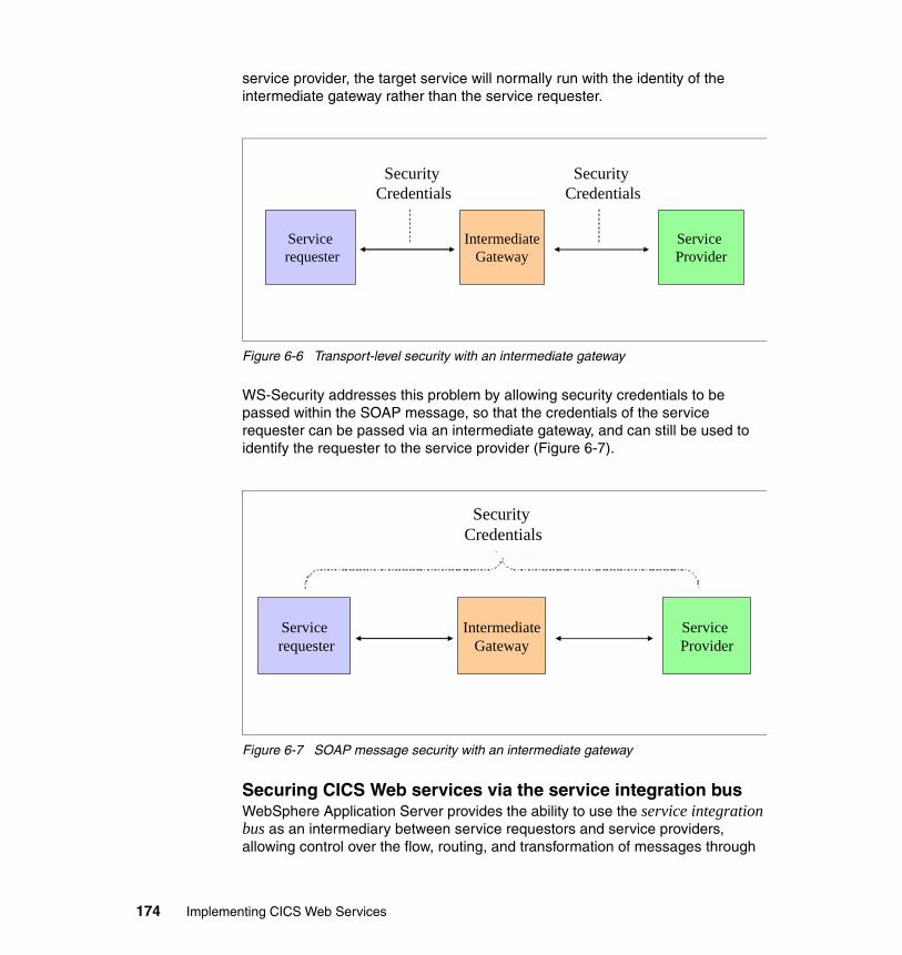
service provider, the target service will normally run with the identity of the intermediate gateway rather than the service requester.
Figure 6-6 Transport-level security with an intermediate gateway
WS-Security addresses this problem by allowing security credentials to be passed within the SOAP message, so that the credentials of the service requester can be passed via an intermediate gateway, and can still be used to identify the requester to the service provider (Figure 6-7).
Figure 6-7 SOAP message security with an intermediate gateway
Securing CICS Web services via the service integration busWebSphere Application Server provides the ability to use the service integration bus as an intermediary between service requestors and service providers, allowing control over the flow, routing, and transformation of messages through
Servicerequester
IntermediateGateway
Service Provider
Security Credentials
Security Credentials
Servicerequester
IntermediateGateway
Service Provider
Security Credentials
174 Implementing CICS Web Services
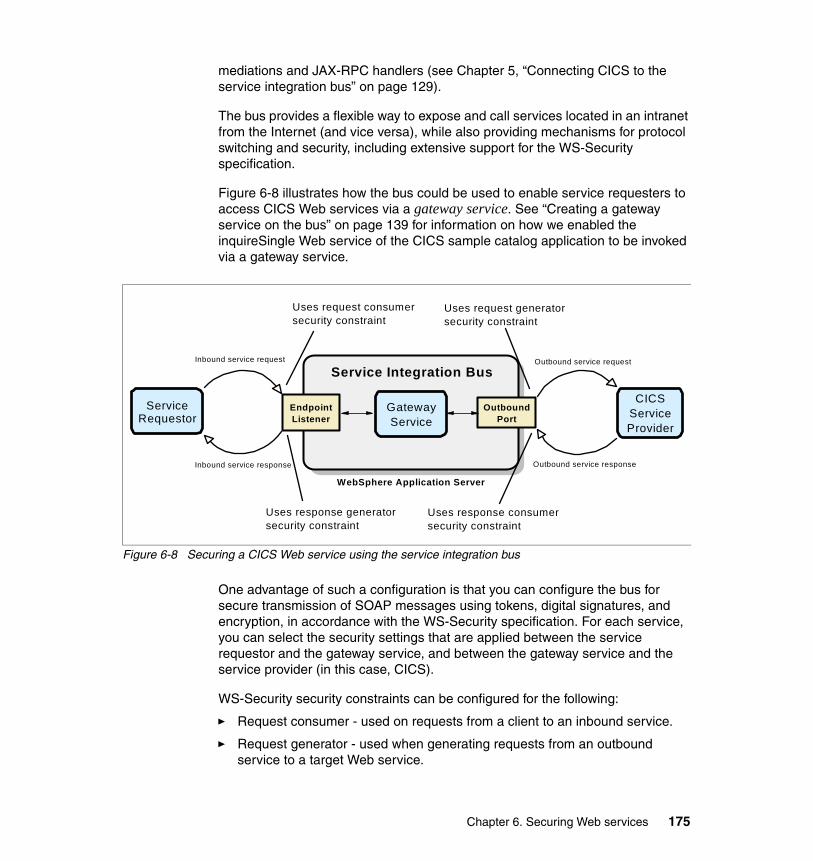
mediations and JAX-RPC handlers (see Chapter 5, “Connecting CICS to the service integration bus” on page 129).
The bus provides a flexible way to expose and call services located in an intranet from the Internet (and vice versa), while also providing mechanisms for protocol switching and security, including extensive support for the WS-Security specification.
Figure 6-8 illustrates how the bus could be used to enable service requesters to access CICS Web services via a gateway service. See “Creating a gateway service on the bus” on page 139 for information on how we enabled the inquireSingle Web service of the CICS sample catalog application to be invoked via a gateway service.
Figure 6-8 Securing a CICS Web service using the service integration bus
One advantage of such a configuration is that you can configure the bus for secure transmission of SOAP messages using tokens, digital signatures, and encryption, in accordance with the WS-Security specification. For each service, you can select the security settings that are applied between the service requestor and the gateway service, and between the gateway service and the service provider (in this case, CICS).
WS-Security security constraints can be configured for the following:
� Request consumer - used on requests from a client to an inbound service.
� Request generator - used when generating requests from an outbound service to a target Web service.
WS-Security bindingsWS-Security configuration
WS-Security bindings
WS-Security configuration
OutboundPort
Service Requestor
Service Integration Bus
CICSServiceProvider
EndpointListener
Inbound service request
Inbound service response
Outbound service request
Outbound service response
Uses response generatorsecurity constraint
Uses request consumersecurity constraint
Uses response consumersecurity constraint
Uses request generatorsecurity constraint
GatewayService
WebSphere Application Server
Chapter 6. Securing Web services 175
� Response consumer - used on responses from a target Web service to an outbound service.
� Response generator - used when generating responses from an inbound service to a client.
The bus can also invoke Web services that include https:// in their addresses. This provides message integrity and confidentiality while the message is transmitted between the bus and the CICS region.
Identity assertionIdentity assertion is an authentication mechanism that is applied among three parties: a client, an intermediary server, and a target server:
� A request message is sent to an intermediary server with a client’s security token.
� The intermediary server authenticates the client and transfers the client’s request message and identity to the target server with the intermediary’s security token.
Identity assertion is an extended security mechanism supported by WebSphere Application Server Version 6.0 and the service integration bus. There are several options of how to send the client’s identity with the intermediary’s token to the target server.
It is possible to use identity assertion to secure a CICS Web service via the bus. For example, for the Gateway service shown in Figure 6-8, we could:
� Define a security requirement for the request consumer such that the requester must provide a binary security token, such as an X.509 certificate.
� Configure WebSphere Application Server to map the certificate to a user identity.
� Define a security requirement for the request generator such that the bus propagates the service requester’s identity to CICS in a UsernameToken.
The bus must establish a trust relationship with the CICS region by authenticating itself and then by being recognized as a trusted partner of the CICS region.
176 Implementing CICS Web Services
Chapter 7. Security scenarios
In this chapter we outline several security scenarios that demonstrate how you can secure a CICS Web services environment.
We start with an explanation of how we prepared the system and the settings that we used for the basic security configuration of our CICS system.
We then provide step-by-step security configuration for a number of scenarios, including:
� Setting the user ID on a URIMAP resource definition
� Enabling SOAP message security with HTTP
� Enabling SSL/TLS
� Enabling SOAP message security with WebSphere MQ
We show how we configured both CICS and WebSphere Application Server for these security scenarios.
7
© Copyright IBM Corp. 2006. All rights reserved. 177
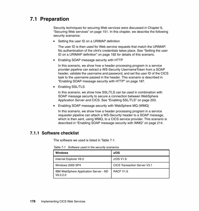
7.1 Preparation
Security techniques for securing Web services were discussed in Chapter 6, “Securing Web services” on page 151. In this chapter, we describe the following security scenarios:
� Setting the user ID on a URIMAP definition
The user ID is then used for Web service requests that match the URIMAP. No authentication of the clint’s credentials takes place. See “Setting the user ID on a URIMAP definition” on page 182 for details of this scenario.
� Enabling SOAP message security with HTTP
In this scenario, we show how a header processing program in a service provider pipeline can extract a WS-Security UsernameToken from a SOAP header, validate the username and password, and set the user ID of the CICS task to the username passed in the header. This scenario is described in “Enabling SOAP message security with HTTP” on page 187.
� Enabling SSL/TLS
In this scenario, we show how SSL/TLS can be used in combination with SOAP message security to secure a connection between WebSphere Application Server and CICS. See “Enabling SSL/TLS” on page 203.
� Enabling SOAP message security with WebSphere MQ (WMQ)
In this scenario, we show how a header processing program in a service requester pipeline can attach a WS-Security header to a SOAP message, which is then sent, using WMQ, to a CICS service provider. This scenario is described in “Enabling SOAP message security with WMQ” on page 214.
7.1.1 Software checklist
The software we used is listed in Table 7-1.
Table 7-1 Software used in the security scenarios
Windows z/OS
Internet Explorer V6.0 z/OS V1.6
Windows 2000 SP4 CICS Transaction Server V3.1
IBM WebSphere Application Server - ND V6.0.2.0
RACF V1.6
178 Implementing CICS Web Services
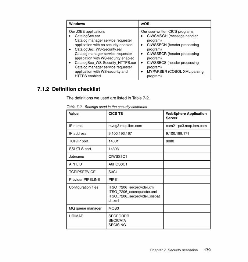
7.1.2 Definition checklist
The definitions we used are listed in Table 7-2.
Table 7-2 Settings used in the security scenarios
Our J2EE applications� CatalogSec.ear
Catalog manager service requester application with no security enabled
� CatalogSec_WS-Security.earCatalog manager service requester application with WS-security enabled
� CatalogSec_WS-Security_HTTPS.earCatalog manager service requester application with WS-security and HTTPS enabled
Our user-written CICS programs� CIWSMSGH (message handler
program)� CIWSSECH (header processing
program)� CIWSSECR (header processing
program)� CIWSSECS (header processing
program)� MYPARSER (COBOL XML parsing
program)
Windows z/OS
Value CICS TS WebSphere Application Server
IP name mvsg3.mop.ibm.com cam21-pc3.mop.ibm.com
IP address 9.100.193.167 9.100.199.171
TCP/IP port 14301 9080
SSL/TLS port 14303
Jobname CIWSS3C1
APPLID A6POS3C1
TCPIPSERVICE S3C1
Provider PIPELINE PIPE1
Configuration files ITSO_7206_secprovider.xmlITSO_7206_secrequester.xmlITSO_7206_secprovider_dispatch.xml
MQ queue manager MQS3
URIMAP SECPORDRSECICATASECISING
Chapter 7. Security scenarios 179
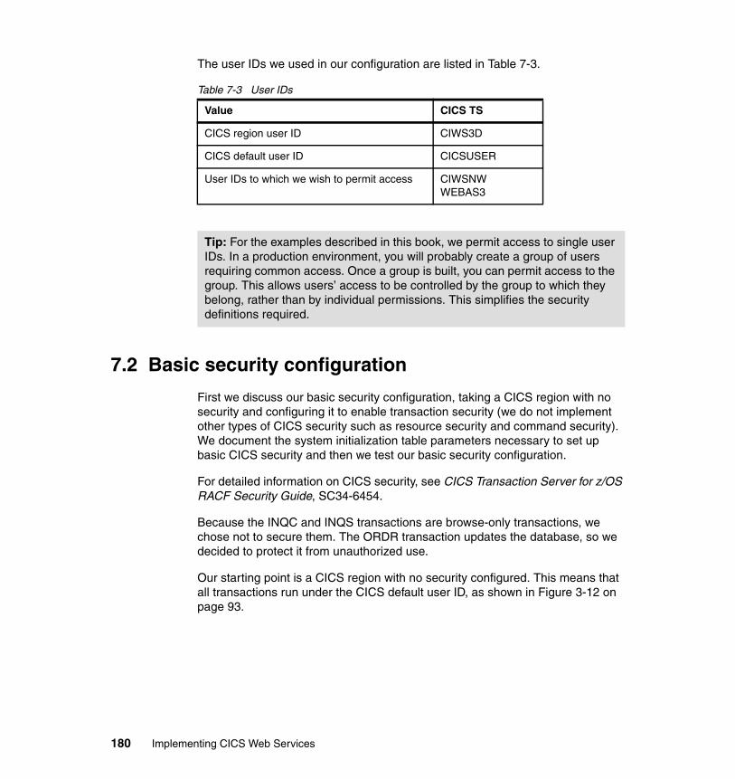
The user IDs we used in our configuration are listed in Table 7-3.
Table 7-3 User IDs
7.2 Basic security configuration
First we discuss our basic security configuration, taking a CICS region with no security and configuring it to enable transaction security (we do not implement other types of CICS security such as resource security and command security). We document the system initialization table parameters necessary to set up basic CICS security and then we test our basic security configuration.
For detailed information on CICS security, see CICS Transaction Server for z/OS RACF Security Guide, SC34-6454.
Because the INQC and INQS transactions are browse-only transactions, we chose not to secure them. The ORDR transaction updates the database, so we decided to protect it from unauthorized use.
Our starting point is a CICS region with no security configured. This means that all transactions run under the CICS default user ID, as shown in Figure 3-12 on page 93.
Value CICS TS
CICS region user ID CIWS3D
CICS default user ID CICSUSER
User IDs to which we wish to permit access CIWSNWWEBAS3
Tip: For the examples described in this book, we permit access to single user IDs. In a production environment, you will probably create a group of users requiring common access. Once a group is built, you can permit access to the group. This allows users’ access to be controlled by the group to which they belong, rather than by individual permissions. This simplifies the security definitions required.
180 Implementing CICS Web Services
7.2.1 Setting up basic security configuration
We configured our CICS region with security prefixing, transaction security, and surrogate user security active using the following SIT parameters:
� SEC=YES� SECPRFX=YES� XTRAN=YES� XUSER=YES
SEC=YES was specified to indicate that we wanted RACF services to control access to CICS resources.
We used security prefixing (SECPRFX=YES) in our CICS region, which prevents our RACF security profiles from affecting other CICS regions. This is useful in a production environment since it means all security profiles are unique to an individual region; however, it can mean more work for the security administrator because more profiles must be defined.
XTRAN=YES was specified so CICS would control who could start transactions and XUSER=YES specifies that CICS is to perform surrogate user checking.
7.2.2 Testing the basic security configuration
After enabling security in our CICS region, we attempted to place an order with the sample catalog application. The Web browser received an error message indicating that the use of some transaction is forbidden (Figure 7-1).
Chapter 7. Security scenarios 181
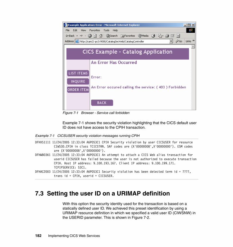
Figure 7-1 Browser - Service call forbidden
Example 7-1 shows the security violation highlighting that the CICS default user ID does not have access to the CPIH transaction.
Example 7-1 CICSUSER security violation messages running CPIH
DFHXS1111 11/24/2005 12:33:04 A6POS3C1 CPIH Security violation by user CICSUSER for resource CIWS3D.CPIH in class TCICSTRN. SAF codes are (X'00000008',X'00000000'). ESM codes are (X'00000008',X'00000000').
DFHWB0361 11/24/2005 12:33:04 A6POS3C1 An attempt to attach a CICS Web alias transaction for userid CICSUSER has failed because the user is not authorized to execute transaction CPIH. Host IP address: 9.100.193.167. Client IP address: 9.100.199.171. TCPIPSERVICE: S3C1.
DFHAC2003 11/24/2005 12:33:04 A6POS3C1 Security violation has been detected term id = ????, trans id = CPIH, userid = CICSUSER.
7.3 Setting the user ID on a URIMAP definition
With this option the security identity used for the transaction is based on a statically defined user ID. We achieved this preset identification by using a URIMAP resource definition in which we specified a valid user ID (CIWSNW) in the USERID parameter. This is shown in Figure 7-2.
182 Implementing CICS Web Services
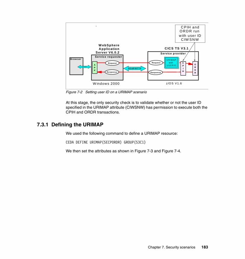
Figure 7-2 Setting user ID on a URIMAP scenario
At this stage, the only security check is to validate whether or not the user ID specified in the URIMAP attribute (CIWSNW) has permission to execute both the CPIH and ORDR transactions.
7.3.1 Defining the URIMAP
We used the following command to define a URIMAP resource:
CEDA DEFINE URIMAP(SECPORDR) GROUP(S3C1)
We then set the attributes as shown in Figure 7-3 and Figure 7-4.
Service requester Service provider
Response R esponse
APP
R equest Request
W ebSphere A pp lication
Server V6.0.2 C IC S TS V3.1
HT T P
Brow ser
SO AP /H TTP
ORDR
CPIH
C PIH and O R D R run w ith user ID
C IW SN W
U R IM APwith
USER ID
W indow s 2000 z/O S V1.6
Chapter 7. Security scenarios 183
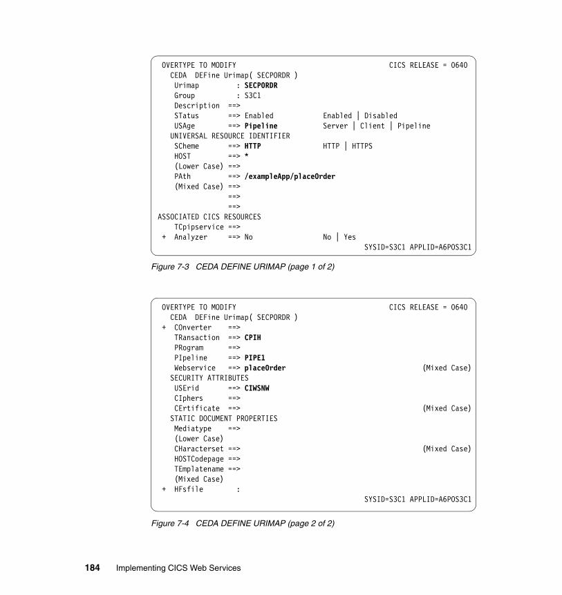
Figure 7-3 CEDA DEFINE URIMAP (page 1 of 2)
Figure 7-4 CEDA DEFINE URIMAP (page 2 of 2)
OVERTYPE TO MODIFY CICS RELEASE = 0640 CEDA DEFine Urimap( SECPORDR ) Urimap : SECPORDR Group : S3C1 Description ==> STatus ==> Enabled Enabled | Disabled USAge ==> Pipeline Server | Client | Pipeline UNIVERSAL RESOURCE IDENTIFIER SCheme ==> HTTP HTTP | HTTPS HOST ==> * (Lower Case) ==> PAth ==> /exampleApp/placeOrder (Mixed Case) ==> ==> ==> ASSOCIATED CICS RESOURCES TCpipservice ==> + Analyzer ==> No No | Yes
SYSID=S3C1 APPLID=A6POS3C1
OVERTYPE TO MODIFY CICS RELEASE = 0640 CEDA DEFine Urimap( SECPORDR ) + COnverter ==> TRansaction ==> CPIH PRogram ==> PIpeline ==> PIPE1 Webservice ==> placeOrder (Mixed Case) SECURITY ATTRIBUTES USErid ==> CIWSNW CIphers ==> CErtificate ==> (Mixed Case) STATIC DOCUMENT PROPERTIES Mediatype ==> (Lower Case) CHaracterset ==> (Mixed Case) HOSTCodepage ==> TEmplatename ==> (Mixed Case) + HFsfile :
SYSID=S3C1 APPLID=A6POS3C1
184 Implementing CICS Web Services
We used the following values:
� URIMAP name was set to SECPORDR.
� USAGE was set to PIPELINE, indicating that it is to be used for incoming Web service requests.
� SCHEME was set to HTTP because no transport security is being used.
� HOST attribute was set to the wildcard (*), meaning that the URIMAP definition matches on any host name.
� PATH was set as /exampleApp/placeOrder. Together with the HOST and SCHEME values this means that the URIMAP resource caters to any Web service request originating from http://*/exampleApp/placeOrder.
� TRANSACTION is automatically defaulted to CPIH by CICS when USAGE(PIPELINE) is specified.
� PIPELINE was set to PIPE1, the name of the pipeline for which this URIMAP definition is being made.
� WEBSERVICE can only be specified when USAGE(PIPELINE) is in effect and specifies the name of the Web service to be invoked. We set the value to placeOrder.
� USERID was set with the value of CIWSNW, the user ID under which we have decided to execute the ORDR transaction.
� All other values were allowed to default.
Two other URIMAP resources were defined with similar definitions. First SECPORDR was copied as SECICATA and as SECISING, then these resource definitions were altered as shown in Example 7-2.
Example 7-2 Creating URIMAP definitions for SECICATA and SECISING
CEDA COPY URIMAP(SECPORDR) GROUP(S3C1) AS(SECICATA)CEDA COPY URIMAP(SECPORDR) GROUP(S3C1) AS(SECISING)CEDA ALTER URIMAP(SECICATA) GROUP(S3C1) PATH(/exampleApp/inquireCatalog)
WEBSERVICE(inquireCatalog)CEDA ALTER URIMAP(SECISING) GROUP(S3C1) PATH(/exampleApp/inquireSingle)
WEBSERVICE(inquireSingle)
This ensures that the transactions INQC, INQS, and ORDR all execute with the same user ID CICSNW.
Example 7-3 shows the RACF commands that we used to permit the CICS region user ID (CIWS3D) to start transactions (such as ORDR) with the user ID CIWSNW.
Chapter 7. Security scenarios 185
Example 7-3 RACF commands to allow CIWS3D to act as surrogate for CIWSNW
RDEFINE SURROGAT CIWSNW.DFHSTART UACC(NONE) OWNER(CIWSNW) PERMIT CIWSNW.DFHSTART CLASS(SURROGAT) ID(CIWS3D) ACCESS(READ) SETROPTS RACLIST(SURROGAT) REFRESH
For more information regarding surrogate user security, see CICS Transaction Server for z/OS RACF Security Guide, SC34-6454.
7.3.2 Permitting access to user ID CICSNW
In “Writing the message handler program” on page 80 we explained how the message handler program CIWSMSGH is used to change the default transaction ID (CPIH) to a transaction ID based on the Web service request in the DFHWS-WEBSERVICE container. Example 7-4 shows the RACF commands that we used to limit access to the ORDR transaction to a single user ID (CIWSNW).
Example 7-4 RACF commands to allow access to CPIH and ORDR transactions
RDEFINE GCICSTRN CIWS3D ADDMEM(CIWS3D.CPIH) UACC(NONE) OWNER(IBMUSER) RALTER GCICSTRN CIWS3D ADDMEM(CIWS3D.ORDR) PERMIT CIWS3D CLASS(GCICSTRN) ID(CIWSNW) ACCESS(READ) SETROPTS RACLIST(TCICSTRN) REFRESH
In Example 7-4 we:
� Define the transaction group CIWS3D and add the CPIH and ORDR transactions to the group
� Permit access to the group for user ID CIWSNW� Refresh the RACF CICS transaction class TCICSTRN
7.3.3 Testing user ID on URIMAP resource definition
With these definitions installed, both the CPIH and ORDR transactions now execute with the user ID as supplied in the URIMAP. This is shown in Figure 7-5.
186 Implementing CICS Web Services
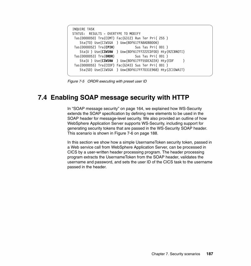
Figure 7-5 ORDR executing with preset user ID
7.4 Enabling SOAP message security with HTTP
In “SOAP message security” on page 164, we explained how WS-Security extends the SOAP specification by defining new elements to be used in the SOAP header for message-level security. We also provided an outline of how WebSphere Application Server supports WS-Security, including support for generating security tokens that are passed in the WS-Security SOAP header. This scenario is shown in Figure 7-6 on page 188.
In this section we show how a simple UsernameToken security token, passed in a Web service call from WebSphere Application Server, can be processed in CICS by a user-written header processing program. The header processing program extracts the UsernameToken from the SOAP header, validates the username and password, and sets the user ID of the CICS task to the username passed in the header.
INQUIRE TASK STATUS: RESULTS - OVERTYPE TO MODIFY Tas(0000050) Tra(CEMT) Fac(G312) Run Ter Pri( 255 ) Sta(TO) Use(CIWSGA ) Uow(BDF617FA8ADB8006) Tas(0000052) Tra(CPIH) Sus Tas Pri( 001 ) Sta(U ) Use(CIWSNW ) Uow(BDF617FF222CDF0D) Hty(RZCBNOTI) Tas(0000053) Tra(ORDR) Sus Tas Pri( 001 ) Sta(U ) Use(CIWSNW ) Uow(BDF617FF55DCA22A) Hty(EDF ) Tas(0000055) Tra(CEDF) Fac(G343) Sus Ter Pri( 001 ) Sta(SD) Use(CIWSGA ) Uow(BDF617FF7D31E968) Hty(ZCIOWAIT)
Chapter 7. Security scenarios 187
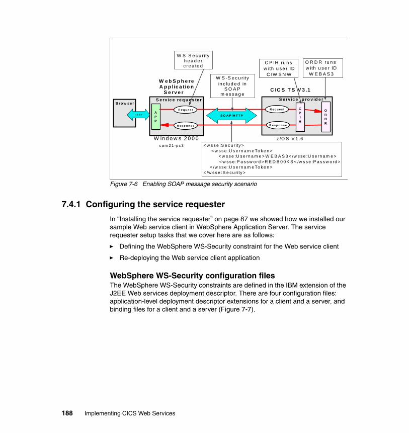
Figure 7-6 Enabling SOAP message security scenario
7.4.1 Configuring the service requester
In “Installing the service requester” on page 87 we showed how we installed our sample Web service client in WebSphere Application Server. The service requester setup tasks that we cover here are as follows:
� Defining the WebSphere WS-Security constraint for the Web service client
� Re-deploying the Web service client application
WebSphere WS-Security configuration filesThe WebSphere WS-Security constraints are defined in the IBM extension of the J2EE Web services deployment descriptor. There are four configuration files: application-level deployment descriptor extensions for a client and a server, and binding files for a client and a server (Figure 7-7).
S e rv ic e re q u e s te r S e rv ic e p ro v id e r
R e s p o n s e R e s p o n s e
APP
R e q u e s t R e q u e s t
W e b S p h e re A p p lic a tio n
S e rv e r
C IC S T S V 3 .1
H T T P
B ro w s e r
S O A P /H T T P
< w s s e :S e c u rity > < w s s e :U s e rn a m e To k e n >
< w s s e :U s e rn a m e > W E B A S 3 < /w s s e :U s e rn a m e > < w s s e :P a s s w o rd > R E D B 0 0 K S < /w s s e :P a s s w o rd >
< /w s s e :U s e rn a m e To k e n > < /w s s e :S e c u rity >
ORDR
CPI
H
W S S e c u r ity h e a d e r c re a te d
W S -S e c u r ityin c lu d e d in
S O A P m e s s a g e
O R D R ru n s w ith u s e r ID
W E B A S 3
C P IH ru n s w ith u s e r ID
C IW S N W
W in d o w s 2 0 0 0 c a m 2 1 -p c 3
z /O S V 1 .6
188 Implementing CICS Web Services
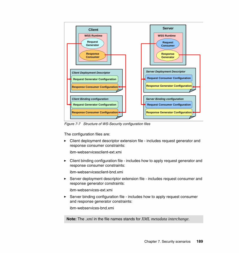
Figure 7-7 Structure of WS-Security configuration files
The configuration files are:
� Client deployment descriptor extension file - includes request generator and response consumer constraints:
ibm-webservicesclient-ext.xmi
� Client binding configuration file - includes how to apply request generator and response consumer constraints:
ibm-webservicesclient-bnd.xmi
� Server deployment descriptor extension file - includes request consumer and response generator constraints:
ibm-webservices-ext.xmi
� Server binding configuration file - includes how to apply request consumer and response generator constraints:
ibm-webservices-bnd.xmi
Note: The .xmi in the file names stands for XML metadata interchange.
WSS Runtime
Request Generator
Response Consumer
WSS Runtime
Request Consumer
Response Generator
Client Server
Client Deployment Descriptor
Client Binding configuration
Server Deployment Descriptor
Server Binding configuration
Request Generator Configuration
Response Consumer Configuration
Request Generator Configuration
Response Consumer Configuration
Request Consumer Configuration
Response Generator Configuration
Request Consumer Configuration
Response Generator Configuration
Chapter 7. Security scenarios 189
The deployment descriptor extension files specify what security constraints are required, for example, what type of security token and whether to sign the message. The binding files specify how to apply the required security constraints defined in the deployment descriptor extension, for example, which security token is inserted and which keys are used for signing.
These deployment descriptor extension and binding files define the application-level security constraints and they belong to each application.
For our scenario, we needed to configure the client deployment descriptor and the client binding only, since our service provider is running in CICS and not in WebSphere Application Server.
Editing the client configurationTo configure our Web service client to use WS-Security, we used Rational Application Developer V6.0 (RAD).
We imported the client application archive CatalogSec.ear into RAD. We then expanded the Dynamic Web Project (CatalogSecWeb) in the Project Explorer and opened (double-clicked) the deployment descriptor.
After the Deployment Descriptor Editor opened, we selected the WS Extension page. The WS Extension page is used for editing the client’s deployment descriptor extension file, so you can specify what security is required. Figure 7-8 shows the WS Extension page in the Deployment Descriptor Editor.
Note: You can also use the Application Server Toolkit to configure WS-Security for WebSphere applications.
190 Implementing CICS Web Services
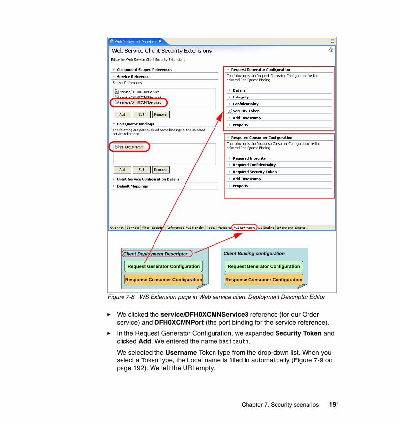
Figure 7-8 WS Extension page in Web service client Deployment Descriptor Editor
� We clicked the service/DFH0XCMNService3 reference (for our Order service) and DFH0XCMNPort (the port binding for the service reference).
� In the Request Generator Configuration, we expanded Security Token and clicked Add. We entered the name basicauth.
We selected the Username Token type from the drop-down list. When you select a Token type, the Local name is filled in automatically (Figure 7-9 on page 192). We left the URI empty.
Client Deployment Descriptor
Request Generator Configuration
Response Consumer Configuration
Client Binding configuration
Request Generator Configuration
Response Consumer Configuration
Chapter 7. Security scenarios 191
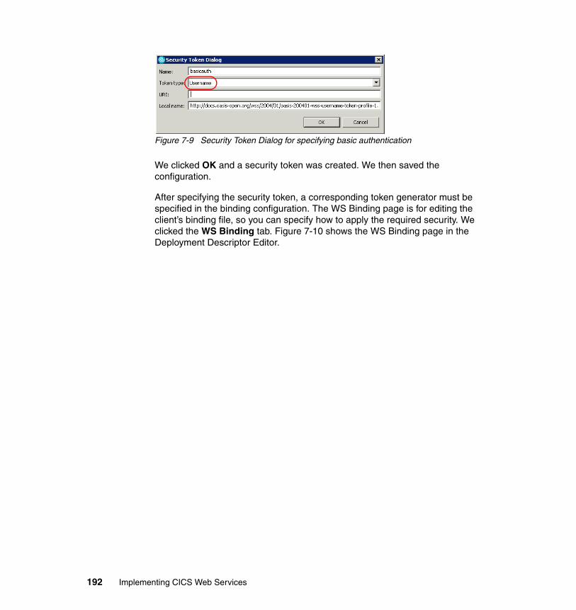
Figure 7-9 Security Token Dialog for specifying basic authentication
We clicked OK and a security token was created. We then saved the configuration.
After specifying the security token, a corresponding token generator must be specified in the binding configuration. The WS Binding page is for editing the client’s binding file, so you can specify how to apply the required security. We clicked the WS Binding tab. Figure 7-10 shows the WS Binding page in the Deployment Descriptor Editor.
192 Implementing CICS Web Services
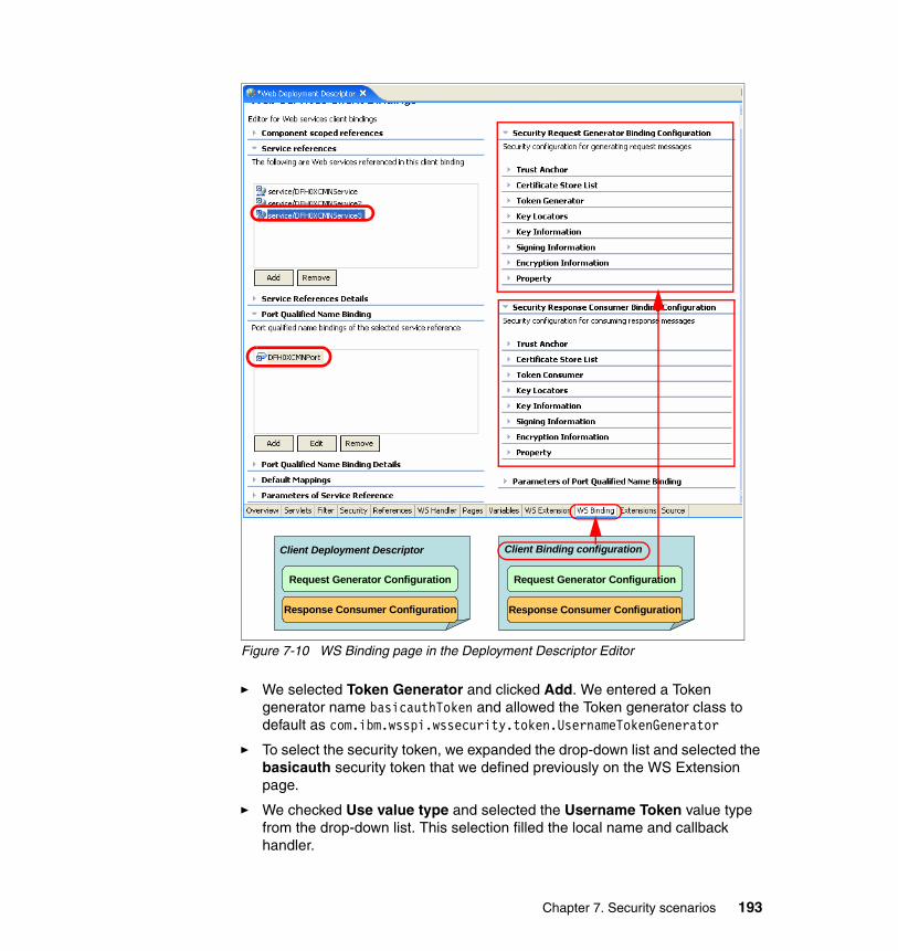
Figure 7-10 WS Binding page in the Deployment Descriptor Editor
� We selected Token Generator and clicked Add. We entered a Token generator name basicauthToken and allowed the Token generator class to default as com.ibm.wsspi.wssecurity.token.UsernameTokenGenerator
� To select the security token, we expanded the drop-down list and selected the basicauth security token that we defined previously on the WS Extension page.
� We checked Use value type and selected the Username Token value type from the drop-down list. This selection filled the local name and callback handler.
Client Deployment Descriptor
Request Generator Configuration
Response Consumer Configuration
Client Binding configuration
Request Generator Configuration
Response Consumer Configuration
Chapter 7. Security scenarios 193
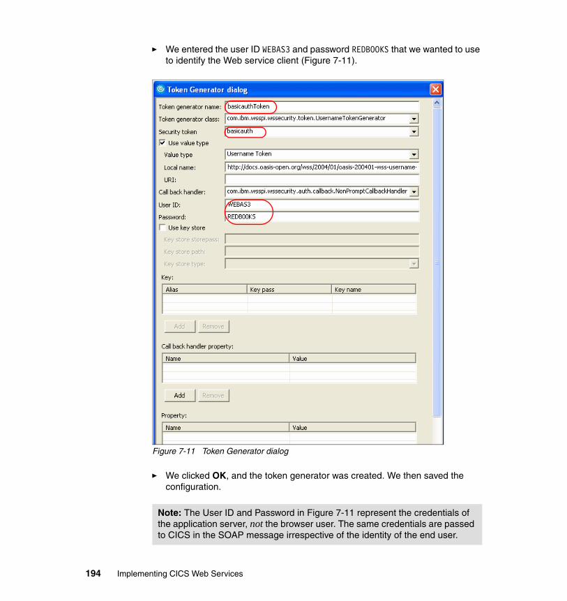
� We entered the user ID WEBAS3 and password REDBOOKS that we wanted to use to identify the Web service client (Figure 7-11).
Figure 7-11 Token Generator dialog
� We clicked OK, and the token generator was created. We then saved the configuration.
Note: The User ID and Password in Figure 7-11 represent the credentials of the application server, not the browser user. The same credentials are passed to CICS in the SOAP message irrespective of the identity of the end user.
194 Implementing CICS Web Services
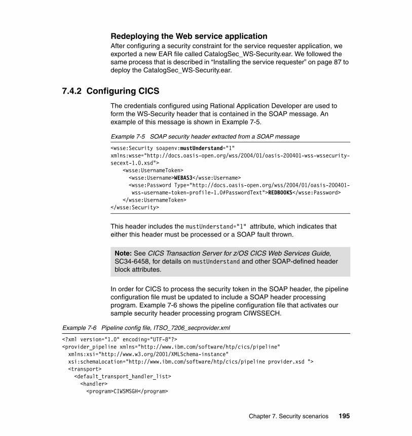
Redeploying the Web service applicationAfter configuring a security constraint for the service requester application, we exported a new EAR file called CatalogSec_WS-Security.ear. We followed the same process that is described in “Installing the service requester” on page 87 to deploy the CatalogSec_WS-Security.ear.
7.4.2 Configuring CICS
The credentials configured using Rational Application Developer are used to form the WS-Security header that is contained in the SOAP message. An example of this message is shown in Example 7-5.
Example 7-5 SOAP security header extracted from a SOAP message
<wsse:Security soapenv:mustUnderstand="1" xmlns:wsse="http://docs.oasis-open.org/wss/2004/01/oasis-200401-wss-wssecurity-secext-1.0.xsd"> <wsse:UsernameToken> <wsse:Username>WEBAS3</wsse:Username>
<wsse:Password Type="http://docs.oasis-open.org/wss/2004/01/oasis-200401-wss-username-token-profile-1.0#PasswordText">REDB00KS</wsse:Password>
</wsse:UsernameToken></wsse:Security>
This header includes the mustUnderstand="1" attribute, which indicates that either this header must be processed or a SOAP fault thrown.
In order for CICS to process the security token in the SOAP header, the pipeline configuration file must be updated to include a SOAP header processing program. Example 7-6 shows the pipeline configuration file that activates our sample security header processing program CIWSSECH.
Example 7-6 Pipeline config file, ITSO_7206_secprovider.xml
<?xml version="1.0" encoding="UTF-8"?> <provider_pipeline xmlns="http://www.ibm.com/software/htp/cics/pipeline" xmlns:xsi="http://www.w3.org/2001/XMLSchema-instance" xsi:schemaLocation="http://www.ibm.com/software/htp/cics/pipeline provider.xsd "> <transport> <default_transport_handler_list> <handler> <program>CIWSMSGH</program>
Note: See CICS Transaction Server for z/OS CICS Web Services Guide, SC34-6458, for details on mustUnderstand and other SOAP-defined header block attributes.
Chapter 7. Security scenarios 195
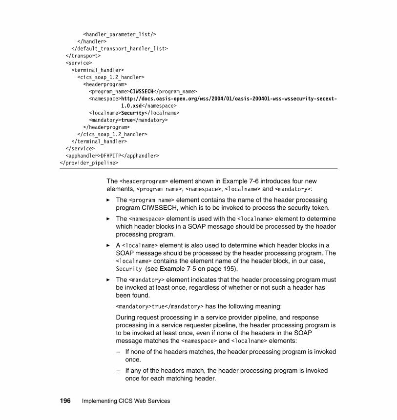
<handler_parameter_list/> </handler> </default_transport_handler_list> </transport> <service> <terminal_handler> <cics_soap_1.2_handler> <headerprogram> <program_name>CIWSSECH</program_name>
<namespace>http://docs.oasis-open.org/wss/2004/01/oasis-200401-wss-wssecurity-secext-1.0.xsd</namespace>
<localname>Security</localname> <mandatory>true</mandatory> </headerprogram> </cics_soap_1.2_handler> </terminal_handler> </service> <apphandler>DFHPITP</apphandler> </provider_pipeline>
The <headerprogram> element shown in Example 7-6 introduces four new elements, <program name>, <namespace>, <localname> and <mandatory>:
� The <program name> element contains the name of the header processing program CIWSSECH, which is to be invoked to process the security token.
� The <namespace> element is used with the <localname> element to determine which header blocks in a SOAP message should be processed by the header processing program.
� A <localname> element is also used to determine which header blocks in a SOAP message should be processed by the header processing program. The <localname> contains the element name of the header block, in our case, Security (see Example 7-5 on page 195).
� The <mandatory> element indicates that the header processing program must be invoked at least once, regardless of whether or not such a header has been found.
<mandatory>true</mandatory> has the following meaning:
During request processing in a service provider pipeline, and response processing in a service requester pipeline, the header processing program is to be invoked at least once, even if none of the headers in the SOAP message matches the <namespace> and <localname> elements:
– If none of the headers matches, the header processing program is invoked once.
– If any of the headers match, the header processing program is invoked once for each matching header.
196 Implementing CICS Web Services
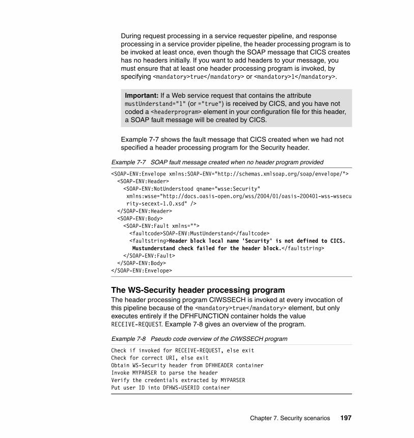
During request processing in a service requester pipeline, and response processing in a service provider pipeline, the header processing program is to be invoked at least once, even though the SOAP message that CICS creates has no headers initially. If you want to add headers to your message, you must ensure that at least one header processing program is invoked, by specifying <mandatory>true</mandatory> or <mandatory>1</mandatory>.
Example 7-7 shows the fault message that CICS created when we had not specified a header processing program for the Security header.
Example 7-7 SOAP fault message created when no header program provided
<SOAP-ENV:Envelope xmlns:SOAP-ENV="http://schemas.xmlsoap.org/soap/envelope/"> <SOAP-ENV:Header> <SOAP-ENV:NotUnderstood qname="wsse:Security"
xmlns:wsse="http://docs.oasis-open.org/wss/2004/01/oasis-200401-wss-wssecurity-secext-1.0.xsd" />
</SOAP-ENV:Header> <SOAP-ENV:Body> <SOAP-ENV:Fault xmlns=""> <faultcode>SOAP-ENV:MustUnderstand</faultcode> <faultstring>Header block local name 'Security' is not defined to CICS.
Mustunderstand check failed for the header block.</faultstring> </SOAP-ENV:Fault> </SOAP-ENV:Body></SOAP-ENV:Envelope>
The WS-Security header processing programThe header processing program CIWSSECH is invoked at every invocation of this pipeline because of the <mandatory>true</mandatory> element, but only executes entirely if the DFHFUNCTION container holds the value RECEIVE-REQUEST. Example 7-8 gives an overview of the program.
Example 7-8 Pseudo code overview of the CIWSSECH program
Check if invoked for RECEIVE-REQUEST, else exitCheck for correct URI, else exitObtain WS-Security header from DFHHEADER containerInvoke MYPARSER to parse the headerVerify the credentials extracted by MYPARSERPut user ID into DFHWS-USERID container
Important: If a Web service request that contains the attribute mustUnderstand="1" (or ="true") is received by CICS, and you have not coded a <headerprogram> element in your configuration file for this header, a SOAP fault message will be created by CICS.
Chapter 7. Security scenarios 197
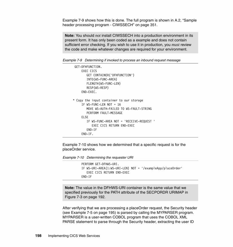
Example 7-9 shows how this is done. The full program is shown in A.2, “Sample header processing program - CIWSSECH” on page 351.
Example 7-9 Determining if invoked to process an inbound request message
GET-DFHFUNCTION. EXEC CICS GET CONTAINER('DFHFUNCTION') INTO(WS-FUNC-AREA) FLENGTH(WS-FUNC-LEN) RESP(WS-RESP) END-EXEC. * Copy the input container to our storage IF WS-FUNC-LEN NOT = 16 MOVE WS-AUTH-FAILED TO WS-FAULT-STRING PERFORM FAULT-MESSAGE ELSE IF WS-FUNC-AREA NOT = 'RECEIVE-REQUEST ' EXEC CICS RETURN END-EXEC END-IF END-IF.
Example 7-10 shows how we determined that a specific request is for the placeOrder service.
Example 7-10 Determining the requester URI
PERFORM GET-DFHWS-URI. IF WS-URI-AREA(1:WS-URI-LEN) NOT = '/exampleApp/placeOrder' EXEC CICS RETURN END-EXEC END-IF
After verifying that we are processing a placeOrder request, the Security header (see Example 7-5 on page 195) is parsed by calling the MYPARSER program. MYPARSER is a user-written COBOL program that uses the COBOL XML PARSE statement to parse through the Security header, extracting the user ID
Note: You should not install CIWSSECH into a production environment in its present form. It has only been coded as a example and does not contain sufficient error checking. If you wish to use it in production, you must review the code and make whatever changes are required for your environment.
Note: The value in the DFHWS-URI container is the same value that we specified previously for the PATH attribute of the SECPORDR URIMAP in Figure 7-3 on page 192.
198 Implementing CICS Web Services
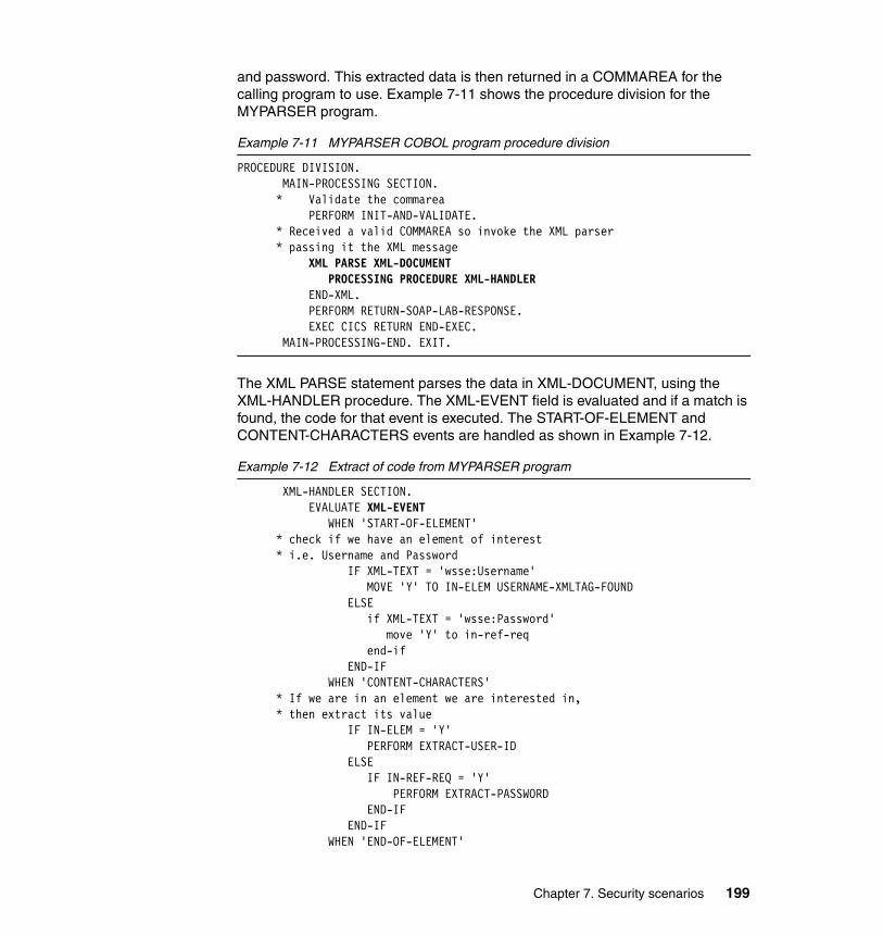
and password. This extracted data is then returned in a COMMAREA for the calling program to use. Example 7-11 shows the procedure division for the MYPARSER program.
Example 7-11 MYPARSER COBOL program procedure division
PROCEDURE DIVISION. MAIN-PROCESSING SECTION. * Validate the commarea PERFORM INIT-AND-VALIDATE. * Received a valid COMMAREA so invoke the XML parser * passing it the XML message XML PARSE XML-DOCUMENT PROCESSING PROCEDURE XML-HANDLER END-XML.
PERFORM RETURN-SOAP-LAB-RESPONSE. EXEC CICS RETURN END-EXEC.
MAIN-PROCESSING-END. EXIT.
The XML PARSE statement parses the data in XML-DOCUMENT, using the XML-HANDLER procedure. The XML-EVENT field is evaluated and if a match is found, the code for that event is executed. The START-OF-ELEMENT and CONTENT-CHARACTERS events are handled as shown in Example 7-12.
Example 7-12 Extract of code from MYPARSER program
XML-HANDLER SECTION. EVALUATE XML-EVENT WHEN 'START-OF-ELEMENT' * check if we have an element of interest * i.e. Username and Password IF XML-TEXT = 'wsse:Username' MOVE 'Y' TO IN-ELEM USERNAME-XMLTAG-FOUND ELSE if XML-TEXT = 'wsse:Password' move 'Y' to in-ref-req end-if END-IF WHEN 'CONTENT-CHARACTERS' * If we are in an element we are interested in, * then extract its value IF IN-ELEM = 'Y' PERFORM EXTRACT-USER-ID ELSE IF IN-REF-REQ = 'Y' PERFORM EXTRACT-PASSWORD END-IF END-IF WHEN 'END-OF-ELEMENT'
Chapter 7. Security scenarios 199
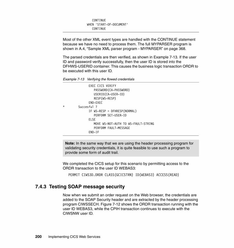
CONTINUE WHEN 'START-OF-DOCUMENT' CONTINUE
Most of the other XML event types are handled with the CONTINUE statement because we have no need to process them. The full MYPARSER program is shown in A.4, “Sample XML parser program - MYPARSER” on page 368.
The parsed credentials are then verified, as shown in Example 7-13. If the user ID and password verify successfully, then the user ID is stored into the DFHWS-USERID container. This causes the business logic transaction ORDR to be executed with this user ID.
Example 7-13 Verifying the flowed credentials
EXEC CICS VERIFY PASSWORD(CA-PASSWORD) USERID(CA-USER-ID) RESP(WS-RESP) END-EXEC * Succesful ? IF WS-RESP = DFHRESP(NORMAL) PERFORM SET-USER-ID ELSE MOVE WS-NOT-AUTH TO WS-FAULT-STRING PERFORM FAULT-MESSAGE END-IF
We completed the CICS setup for this scenario by permitting access to the ORDR transaction to the user ID WEBAS3:
PERMIT CIWS3D.ORDR CLASS(GCICSTRN) ID(WEBAS3) ACCESS(READ)
7.4.3 Testing SOAP message security
Now when we submit an order request on the Web browser, the credentials are added to the SOAP Security header and are extracted by the header processing program CIWSSECH. Figure 7-12 shows the ORDR transaction running with the user ID WEBAS3, while the CPIH transaction continues to execute with the CIWSNW user ID.
Note: In the same way that we are using the header processing program for validating security credentials, it is quite feasible to use such a program to provide some form of audit trail.
200 Implementing CICS Web Services
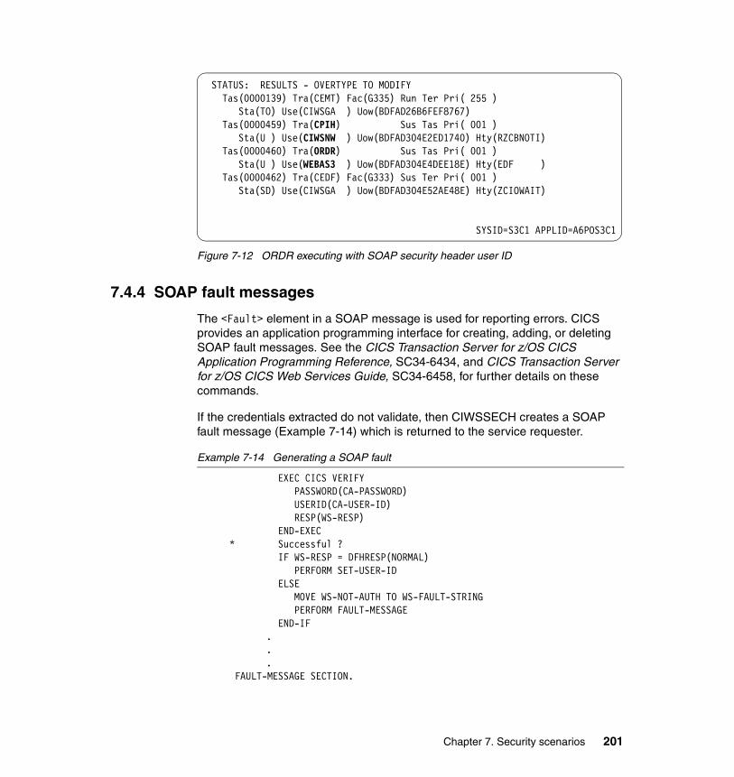
Figure 7-12 ORDR executing with SOAP security header user ID
7.4.4 SOAP fault messages
The <Fault> element in a SOAP message is used for reporting errors. CICS provides an application programming interface for creating, adding, or deleting SOAP fault messages. See the CICS Transaction Server for z/OS CICS Application Programming Reference, SC34-6434, and CICS Transaction Server for z/OS CICS Web Services Guide, SC34-6458, for further details on these commands.
If the credentials extracted do not validate, then CIWSSECH creates a SOAP fault message (Example 7-14) which is returned to the service requester.
Example 7-14 Generating a SOAP fault
EXEC CICS VERIFY PASSWORD(CA-PASSWORD) USERID(CA-USER-ID) RESP(WS-RESP) END-EXEC * Successful ? IF WS-RESP = DFHRESP(NORMAL) PERFORM SET-USER-ID ELSE MOVE WS-NOT-AUTH TO WS-FAULT-STRING PERFORM FAULT-MESSAGE END-IF
.
.
.FAULT-MESSAGE SECTION.
STATUS: RESULTS - OVERTYPE TO MODIFY Tas(0000139) Tra(CEMT) Fac(G335) Run Ter Pri( 255 ) Sta(TO) Use(CIWSGA ) Uow(BDFAD26B6FEF8767) Tas(0000459) Tra(CPIH) Sus Tas Pri( 001 ) Sta(U ) Use(CIWSNW ) Uow(BDFAD304E2ED1740) Hty(RZCBNOTI) Tas(0000460) Tra(ORDR) Sus Tas Pri( 001 ) Sta(U ) Use(WEBAS3 ) Uow(BDFAD304E4DEE18E) Hty(EDF ) Tas(0000462) Tra(CEDF) Fac(G333) Sus Ter Pri( 001 ) Sta(SD) Use(CIWSGA ) Uow(BDFAD304E52AE48E) Hty(ZCIOWAIT)
SYSID=S3C1 APPLID=A6POS3C1
Chapter 7. Security scenarios 201
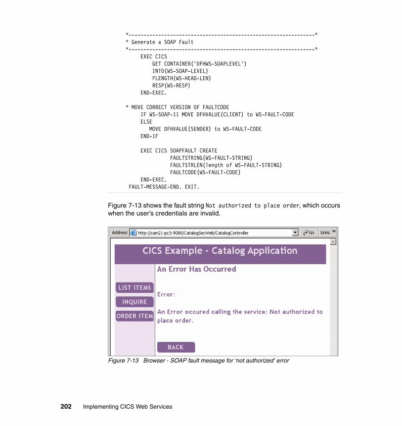
*---------------------------------------------------------------* * Generate a SOAP Fault *---------------------------------------------------------------* EXEC CICS GET CONTAINER('DFHWS-SOAPLEVEL') INTO(WS-SOAP-LEVEL) FLENGTH(WS-HEAD-LEN) RESP(WS-RESP) END-EXEC. * MOVE CORRECT VERSION OF FAULTCODE IF WS-SOAP-11 MOVE DFHVALUE(CLIENT) to WS-FAULT-CODE ELSE MOVE DFHVALUE(SENDER) to WS-FAULT-CODE END-IF EXEC CICS SOAPFAULT CREATE FAULTSTRING(WS-FAULT-STRING) FAULTSTRLEN(length of WS-FAULT-STRING) FAULTCODE(WS-FAULT-CODE) END-EXEC. FAULT-MESSAGE-END. EXIT.
Figure 7-13 shows the fault string Not authorized to place order, which occurs when the user’s credentials are invalid.
Figure 7-13 Browser - SOAP fault message for ‘not authorized’ error
202 Implementing CICS Web Services
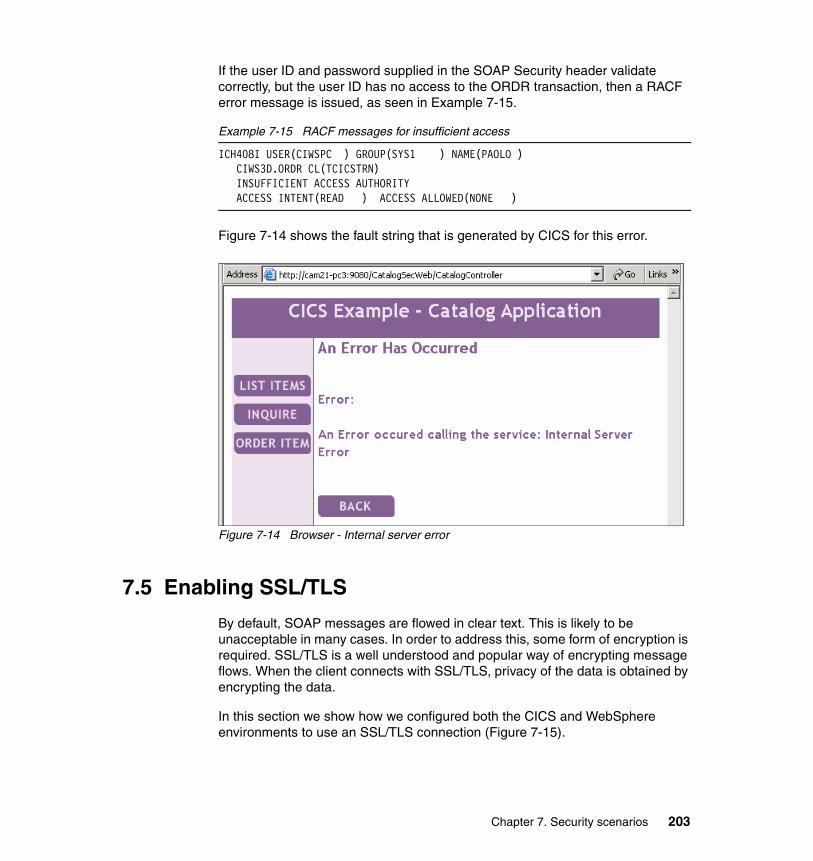
If the user ID and password supplied in the SOAP Security header validate correctly, but the user ID has no access to the ORDR transaction, then a RACF error message is issued, as seen in Example 7-15.
Example 7-15 RACF messages for insufficient access
ICH408I USER(CIWSPC ) GROUP(SYS1 ) NAME(PAOLO ) CIWS3D.ORDR CL(TCICSTRN) INSUFFICIENT ACCESS AUTHORITY ACCESS INTENT(READ ) ACCESS ALLOWED(NONE )
Figure 7-14 shows the fault string that is generated by CICS for this error.
Figure 7-14 Browser - Internal server error
7.5 Enabling SSL/TLS
By default, SOAP messages are flowed in clear text. This is likely to be unacceptable in many cases. In order to address this, some form of encryption is required. SSL/TLS is a well understood and popular way of encrypting message flows. When the client connects with SSL/TLS, privacy of the data is obtained by encrypting the data.
In this section we show how we configured both the CICS and WebSphere environments to use an SSL/TLS connection (Figure 7-15).
Chapter 7. Security scenarios 203
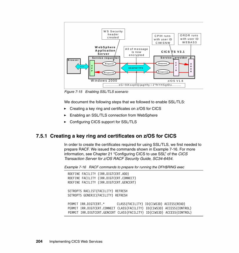
Figure 7-15 Enabling SSL/TLS scenario
We document the following steps that we followed to enable SSL/TLS:
� Creating a key ring and certificates on z/OS for CICS
� Enabling an SSL/TLS connection from WebSphere
� Configuring CICS support for SSL/TLS
7.5.1 Creating a key ring and certificates on z/OS for CICS
In order to create the certificates required for using SSL/TLS, we first needed to prepare RACF. We issued the commands shown in Example 7-16. For more information, see Chapter 21 “Configuring CICS to use SSL” of the CICS Transaction Server for z/OS RACF Security Guide, SC34-6454.
Example 7-16 RACF commands to prepare for running the DFH$RING exec
RDEFINE FACILITY (IRR.DIGTCERT.ADD) RDEFINE FACILITY (IRR.DIGTCERT.CONNECT) RDEFINE FACILITY (IRR.DIGTCERT.GENCERT)
SETROPTS RACLIST(FACILITY) REFRESH SETROPTS GENERIC(FACILITY) REFRESH
PERMIT IRR.DIGTCERT.* CLASS(FACILITY) ID(CIWS3D) ACCESS(READ) PERMIT IRR.DIGTCERT.CONNECT CLASS(FACILITY) ID(CIWS3D) ACCESS(CONTROL) PERMIT IRR.DIGTCERT.GENCERT CLASS(FACILITY) ID(CIWS3D) ACCESS(CONTROL)
S e rv ic e re q u e s te r S e rv ic e p ro v id e r
R e s p o n s e R e s p o n s e
APP
R e q u e s t R e q u e s t
W e b S p h e re A p p lic a tio n
S e rv e r
C IC S T S V 3 .1
H T T P
B ro w s e r
S O A P /H T T P S
W S S e cu rity h e a d e r c re a te d
O R D R ru n s w ith u s e r ID
W E B A S 3
. . . . . .. . . .. . . . .e G + 9 iK s o p 0 Q ija g h fty .\ 2 " fh Y H S g tD u ..... . . . . .
ORDR
CPI
H
A ll o f m e s s a g e is n o w
e n c ryp te d
C P IH ru n s w ith u s e r ID
C IW S N W
z /O S V 1 .6W in d o w s 2 0 0 0
204 Implementing CICS Web Services
The sample clist DFH$RING is provided by CICS TS to help you build a RACF KEYRING for CICS SSL use. We copied the DFH$RING clist from hlq.SDFHSAMP into our own private library and modified the clist using the customization values shown in Table 7-4.
Table 7-4 Customizing the DFH$RING clist - Site settings
These values represent the entity for which we are creating the certificates and key ring. As can be seen, these were chosen to indicate the IBM site where the Redbook residency was held.
Further parameters were supplied as input to the clist for the specific key ring to be created (Table 7-5).
Table 7-5 Customizing the DFH$RING clist - Key ring settings
The name of the key ring to be created is Ciws.Ciwss3c1. The userid parameter was supplied as CIWS3D (the CICS region user ID). The ipname is the address of the z/OS on which our CICS region CIWSS3C1 runs.
Further modifications were made to the clist because we chose not to generate certificates for a Web server or for an EJB container. Instead we generated certificates for a Web service Client, Web service Server, and a default certificate. These changes are shown in Example 7-17.
Name Value
organization ITSO
department PSSC
certifier CICS-Sample-Certification
city Montpellier
state Herault
country FR
Name Value
firstname Ciws
lastname Ciws3c1
ipname mvsg3.mop.ibm.com
userid CIWS3D
Chapter 7. Security scenarios 205
Example 7-17 Customizing the DFH$RING EXEC - certificate labels
"RACDCERT ID("foruser") DELETE(LABEL('"lastname"-Web-service-Client'))" "RACDCERT ID("foruser") DELETE(LABEL('"lastname"-Web-service-Server'))" "RACDCERT ID("foruser") DELETE(LABEL('"lastname"-Default-Certificate'))"
We used the batch job shown in Example 7-18 to execute the DFH$RING clist in order to create the required RACF profiles.
Example 7-18 Batch job to invoke the DFH$RING clist
//REXXJOB JOB 1,CIWS,TIME=1440,NOTIFY=&SYSUID,REGION=4M, // CLASS=A,MSGCLASS=X,MSGLEVEL=(1,1) //* //REXX EXEC PGM=IKJEFT01 //SYSPROC DD DISP=SHR,DSN=CIWS.CICS.JCL //SYSTSPRT DD SYSOUT=* //SYSOUT DD SYSOUT=* //SYSTSIN DD * %DFH$RING CIWS CIWSS3C1 mvsg3.mop.ibm.com FORUSER(CIWS3D) /*
To complete this part of the configuration we exported the Certificate Authority (CA) certificate in Base64 X.509 format using the RACF RACDCERT command:
RACDCERT CERTAUTH EXPORT(LABEL(‘CICS-Sample-Certification’)) + DSN(CIWSGA.CERTAUTH.X509) FORMAT(CERTB64)
7.5.2 Enabling an SSL/TLS connection from WebSphere
To enable an SSL/TLS connection from WebSphere we did the following:
� FTPed the certificate from z/OS to our client machine
� Imported the certificate into the WebSphere Application Server keystore
� Enabled the service requester to use HTTPS
FTP the certificate from z/OSWe used FTP as shown in Example 7-19 to send the exported certificate in ASCII format to our client machine.
Example 7-19 Using FTP to send an exported CA certificate to a client workstation
C:\>ftp mvsg3.mop.ibm.comConnected to mvsg3.mop.ibm.com.220-FTPD1 IBM FTP CS V1R6 at MVSG3.pssc.mop.ibm.com, 13:23:10 on 2005-11-30.220 Connection will close if idle for more than 5 minutes.User (mvsg3.mop.ibm.com:(none)): ciwsga
206 Implementing CICS Web Services
331 Send password please.Password:230 CIWSGA is logged on. Working directory is "CIWSGA.".ftp> ascii200 Representation type is Ascii NonPrintftp> get CERTAUTH.X509200 Port request OK.125 Sending data set CIWSGA.CERTAUTH.X509250 Transfer completed successfully.ftp: 1022 bytes received in 0.00Seconds 1022000.00Kbytes/sec.ftp> quit221 Quit command received. Goodbye.
Importing the certificateNext, we needed to make the CERTAUTH.X509 certificate available for use by WebSphere Application Server. To do this, we imported the CERTAUTH.X509 certificate to the WebSphere Application Server keystore (DummyServerKeyFile.jks) using iKeyMan.
After opening a command prompt window we set the PATH variable and typed ikeyman to invoke the iKeyMan GUI.
set PATH=C:\Program Files\IBM\Java142\jre\bin\;%PATH%ikeyman
We used iKeyMan to add the CERTAUTH.X509 file to the WebSphere Application Server keystore (ServerKeyFile.jks) as shown in Figure 7-16.
Note: The iKeyMan tool is provided by the IBM Java SDK. On our workstation the tool was located in directory C:\Program Files\IBM\Java142\jre\bin.
Chapter 7. Security scenarios 207
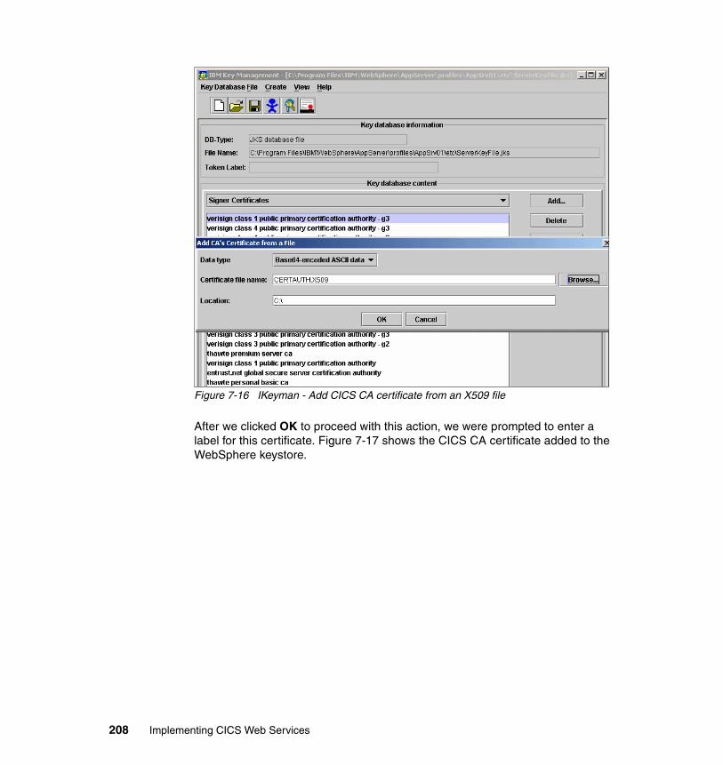
Figure 7-16 IKeyman - Add CICS CA certificate from an X509 file
After we clicked OK to proceed with this action, we were prompted to enter a label for this certificate. Figure 7-17 shows the CICS CA certificate added to the WebSphere keystore.
208 Implementing CICS Web Services
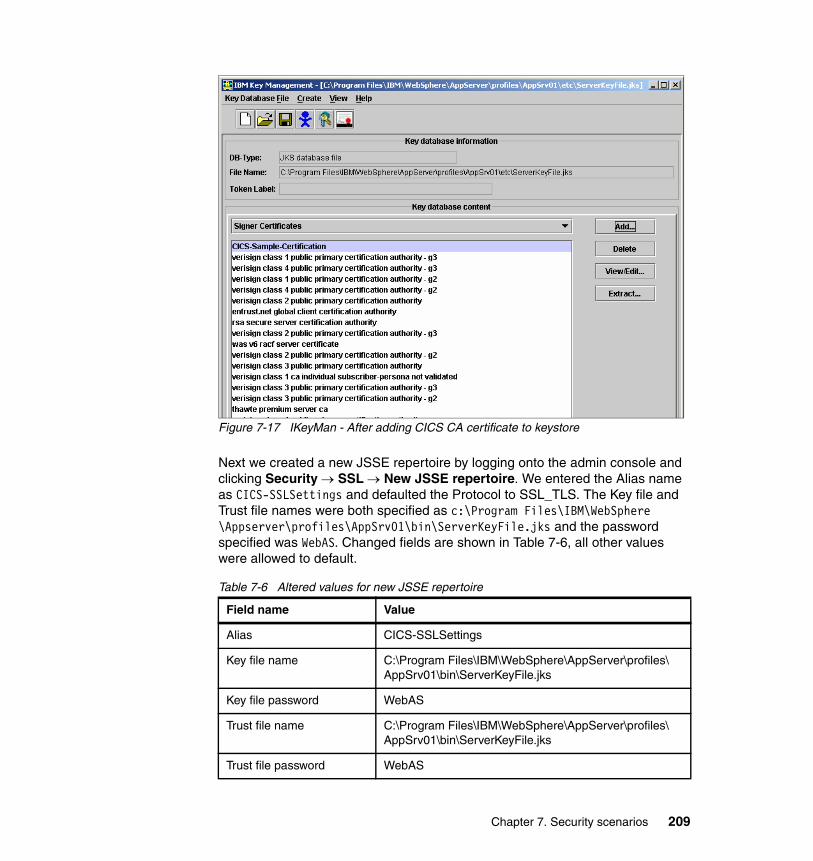
Figure 7-17 IKeyMan - After adding CICS CA certificate to keystore
Next we created a new JSSE repertoire by logging onto the admin console and clicking Security → SSL → New JSSE repertoire. We entered the Alias name as CICS-SSLSettings and defaulted the Protocol to SSL_TLS. The Key file and Trust file names were both specified as c:\Program Files\IBM\WebSphere \Appserver\profiles\AppSrv01\bin\ServerKeyFile.jks and the password specified was WebAS. Changed fields are shown in Table 7-6, all other values were allowed to default.
Table 7-6 Altered values for new JSSE repertoire
Field name Value
Alias CICS-SSLSettings
Key file name C:\Program Files\IBM\WebSphere\AppServer\profiles\AppSrv01\bin\ServerKeyFile.jks
Key file password WebAS
Trust file name C:\Program Files\IBM\WebSphere\AppServer\profiles\AppSrv01\bin\ServerKeyFile.jks
Trust file password WebAS
Chapter 7. Security scenarios 209
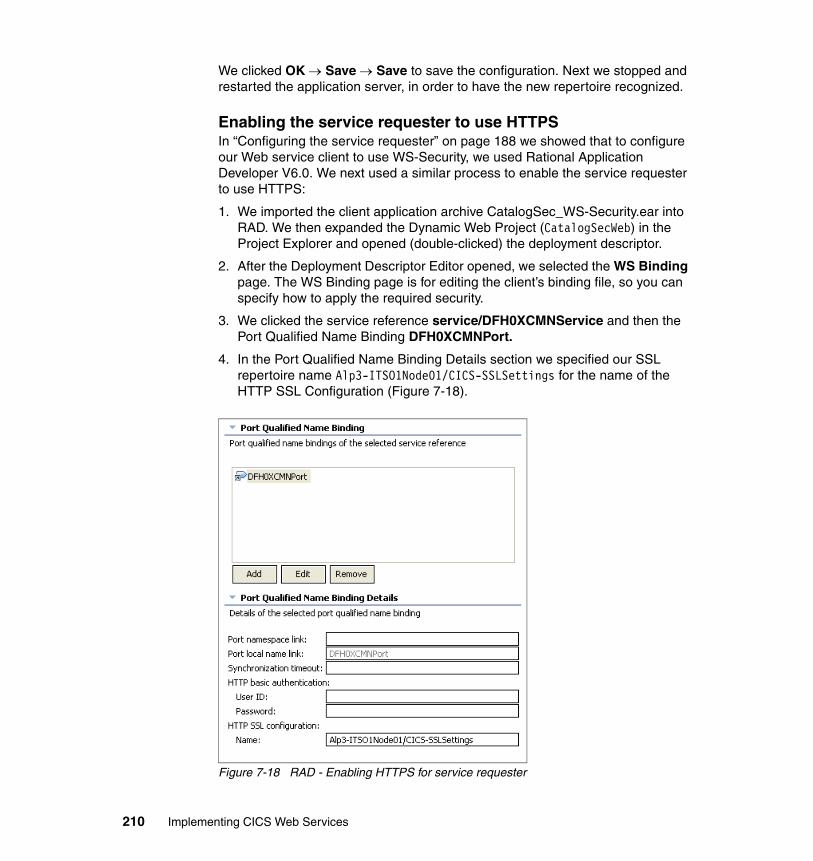
We clicked OK → Save → Save to save the configuration. Next we stopped and restarted the application server, in order to have the new repertoire recognized.
Enabling the service requester to use HTTPSIn “Configuring the service requester” on page 188 we showed that to configure our Web service client to use WS-Security, we used Rational Application Developer V6.0. We next used a similar process to enable the service requester to use HTTPS:
1. We imported the client application archive CatalogSec_WS-Security.ear into RAD. We then expanded the Dynamic Web Project (CatalogSecWeb) in the Project Explorer and opened (double-clicked) the deployment descriptor.
2. After the Deployment Descriptor Editor opened, we selected the WS Binding page. The WS Binding page is for editing the client’s binding file, so you can specify how to apply the required security.
3. We clicked the service reference service/DFH0XCMNService and then the Port Qualified Name Binding DFH0XCMNPort.
4. In the Port Qualified Name Binding Details section we specified our SSL repertoire name Alp3-ITSO1Node01/CICS-SSLSettings for the name of the HTTP SSL Configuration (Figure 7-18).
Figure 7-18 RAD - Enabling HTTPS for service requester
210 Implementing CICS Web Services
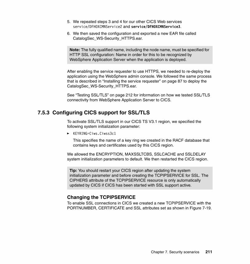
5. We repeated steps 3 and 4 for our other CICS Web services service/DFH0XCMNService2 and service/DFH0XCMNService3.
6. We then saved the configuration and exported a new EAR file called CatalogSec_WS-Security_HTTPS.ear.
After enabling the service requester to use HTTPS, we needed to re-deploy the application using the WebSphere admin console. We followed the same process that is described in “Installing the service requester” on page 87 to deploy the CatalogSec_WS-Security_HTTPS.ear.
See “Testing SSL/TLS” on page 212 for information on how we tested SSL/TLS connectivity from WebSphere Application Server to CICS.
7.5.3 Configuring CICS support for SSL/TLS
To activate SSL/TLS support in our CICS TS V3.1 region, we specified the following system initialization parameter:
� KEYRING=Ciws.Ciwss3c1
This specifies the name of a key ring we created in the RACF database that contains keys and certificates used by this CICS region.
We allowed the ENCRYPTION, MAXSSLTCBS, SSLCACHE and SSLDELAY system initialization parameters to default. We then restarted the CICS region.
Changing the TCPIPSERVICETo enable SSL connections in CICS we created a new TCPIPSERVICE with the PORTNUMBER, CERTIFICATE and SSL attributes set as shown in Figure 7-19.
Note: The fully qualified name, including the node name, must be specified for HTTP SSL configuration: Name in order for this to be recognized by WebSphere Application Server when the application is deployed.
Tip: You should restart your CICS region after updating the system initialization parameter and before creating the TCPIPSERVICE for SSL. The CIPHERS attribute of the TCPIPSERVICE resource is only automatically updated by CICS if CICS has been started with SSL support active.
Chapter 7. Security scenarios 211
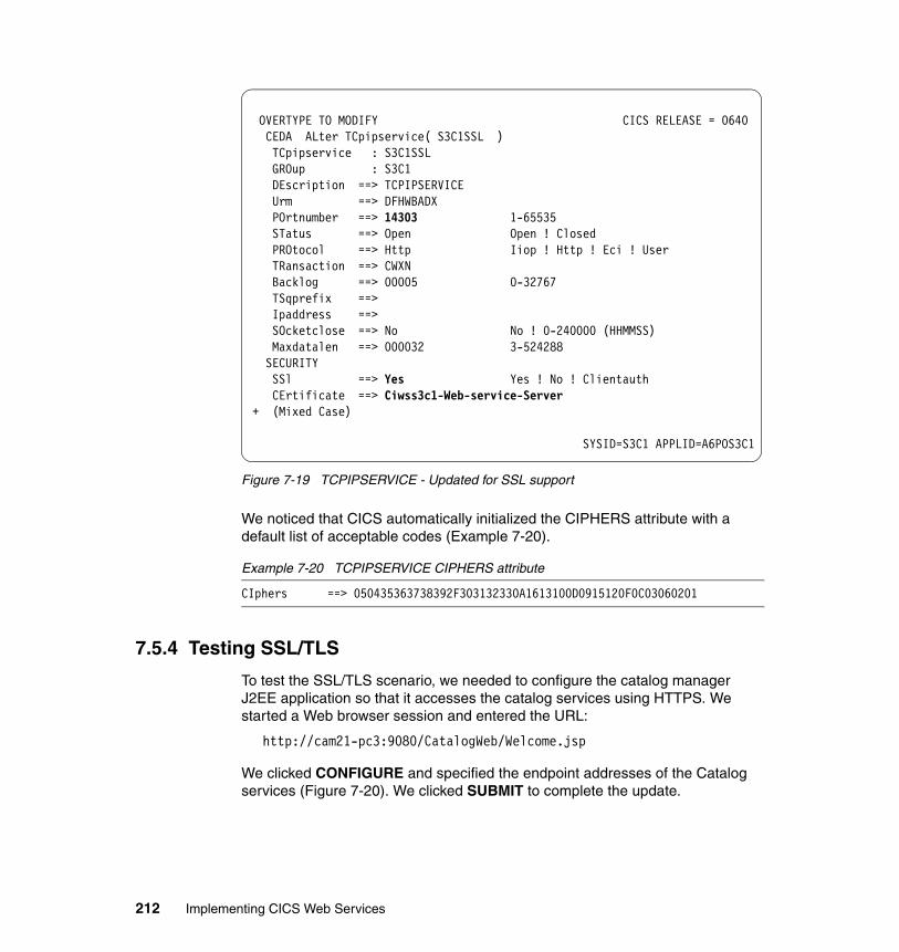
Figure 7-19 TCPIPSERVICE - Updated for SSL support
We noticed that CICS automatically initialized the CIPHERS attribute with a default list of acceptable codes (Example 7-20).
Example 7-20 TCPIPSERVICE CIPHERS attribute
CIphers ==> 050435363738392F303132330A1613100D0915120F0C03060201
7.5.4 Testing SSL/TLS
To test the SSL/TLS scenario, we needed to configure the catalog manager J2EE application so that it accesses the catalog services using HTTPS. We started a Web browser session and entered the URL:
http://cam21-pc3:9080/CatalogWeb/Welcome.jsp
We clicked CONFIGURE and specified the endpoint addresses of the Catalog services (Figure 7-20). We clicked SUBMIT to complete the update.
OVERTYPE TO MODIFY CICS RELEASE = 0640 CEDA ALter TCpipservice( S3C1SSL ) TCpipservice : S3C1SSL GROup : S3C1 DEscription ==> TCPIPSERVICE Urm ==> DFHWBADX POrtnumber ==> 14303 1-65535 STatus ==> Open Open ! Closed PROtocol ==> Http Iiop ! Http ! Eci ! User TRansaction ==> CWXN Backlog ==> 00005 0-32767 TSqprefix ==> Ipaddress ==> SOcketclose ==> No No ! 0-240000 (HHMMSS) Maxdatalen ==> 000032 3-524288 SECURITY SSl ==> Yes Yes ! No ! Clientauth CErtificate ==> Ciwss3c1-Web-service-Server + (Mixed Case)
SYSID=S3C1 APPLID=A6POS3C1
212 Implementing CICS Web Services
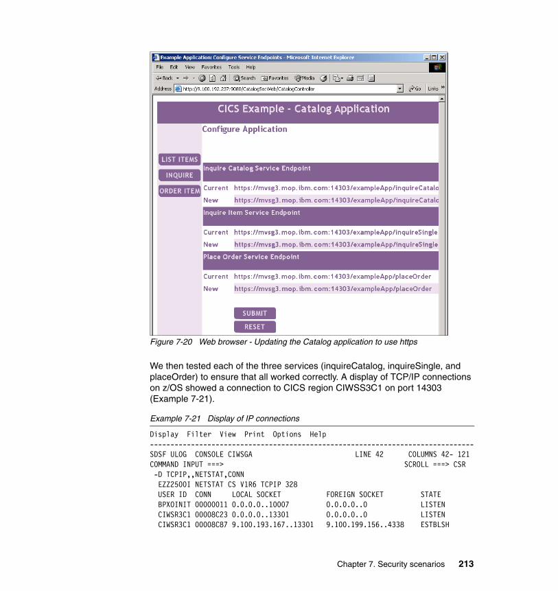
Figure 7-20 Web browser - Updating the Catalog application to use https
We then tested each of the three services (inquireCatalog, inquireSingle, and placeOrder) to ensure that all worked correctly. A display of TCP/IP connections on z/OS showed a connection to CICS region CIWSS3C1 on port 14303 (Example 7-21).
Example 7-21 Display of IP connections
Display Filter View Print Options Help -------------------------------------------------------------------------------SDSF ULOG CONSOLE CIWSGA LINE 42 COLUMNS 42- 121 COMMAND INPUT ===> SCROLL ===> CSR -D TCPIP,,NETSTAT,CONN EZZ2500I NETSTAT CS V1R6 TCPIP 328 USER ID CONN LOCAL SOCKET FOREIGN SOCKET STATE BPXOINIT 00000011 0.0.0.0..10007 0.0.0.0..0 LISTEN CIWSR3C1 00008C23 0.0.0.0..13301 0.0.0.0..0 LISTEN CIWSR3C1 00008C87 9.100.193.167..13301 9.100.199.156..4338 ESTBLSH
Chapter 7. Security scenarios 213
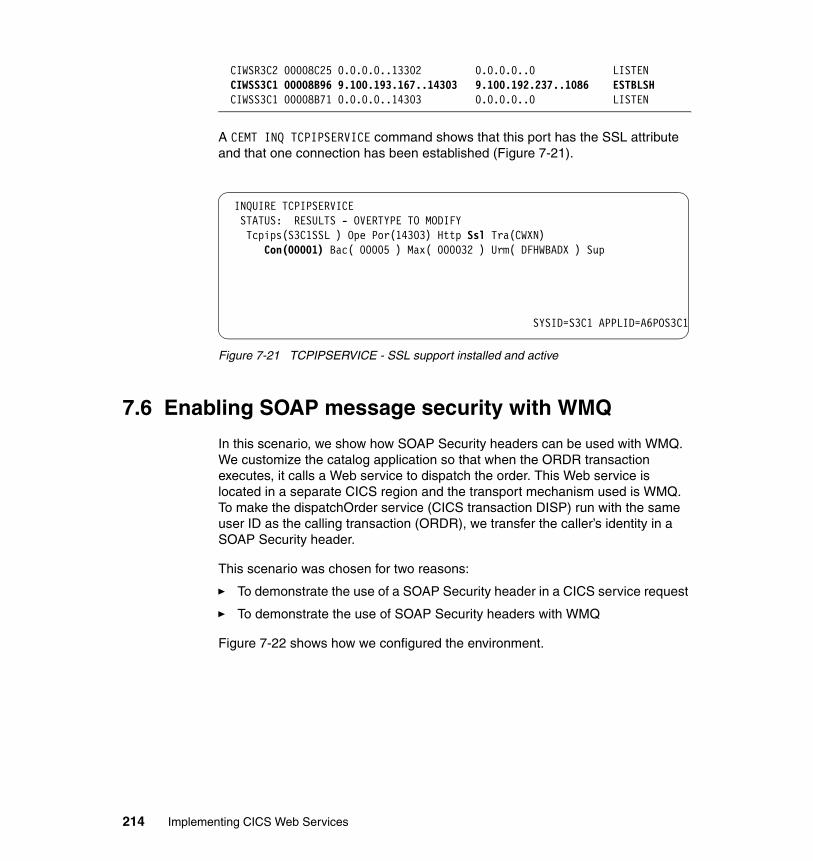
CIWSR3C2 00008C25 0.0.0.0..13302 0.0.0.0..0 LISTEN CIWSS3C1 00008B96 9.100.193.167..14303 9.100.192.237..1086 ESTBLSH CIWSS3C1 00008B71 0.0.0.0..14303 0.0.0.0..0 LISTEN
A CEMT INQ TCPIPSERVICE command shows that this port has the SSL attribute and that one connection has been established (Figure 7-21).
Figure 7-21 TCPIPSERVICE - SSL support installed and active
7.6 Enabling SOAP message security with WMQ
In this scenario, we show how SOAP Security headers can be used with WMQ. We customize the catalog application so that when the ORDR transaction executes, it calls a Web service to dispatch the order. This Web service is located in a separate CICS region and the transport mechanism used is WMQ. To make the dispatchOrder service (CICS transaction DISP) run with the same user ID as the calling transaction (ORDR), we transfer the caller’s identity in a SOAP Security header.
This scenario was chosen for two reasons:
� To demonstrate the use of a SOAP Security header in a CICS service request
� To demonstrate the use of SOAP Security headers with WMQ
Figure 7-22 shows how we configured the environment.
INQUIRE TCPIPSERVICE STATUS: RESULTS - OVERTYPE TO MODIFY Tcpips(S3C1SSL ) Ope Por(14303) Http Ssl Tra(CWXN) Con(00001) Bac( 00005 ) Max( 000032 ) Urm( DFHWBADX ) Sup
SYSID=S3C1 APPLID=A6POS3C1
214 Implementing CICS Web Services
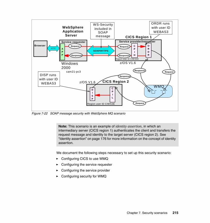
Figure 7-22 SOAP message security with WebSphere MQ scenario
We document the following steps necessary to set up this security scenario:
� Configuring CICS to use WMQ
� Configuring the service requester
� Configuring the service provider
� Configuring security for WMQ
Service requester Service provider/requester
Response Response
APP
Request Request
WebSphere Application
Server
CICS Region 1
HTTPBrowser
SOAP/HTTPS
CPIH
ORDR runs with user ID
WEBAS3
z/OS V1.6Windows 2000 cam21-pc3
CPIL
DISP
CICS Region 2
Region user ID CIWS3E
Region user ID CIW S3D
z/OS V1.6
DISP runs with user ID
WEBAS3WMQ
Request
Request
Response
Response
WS-Securityincluded in
SOAP message
ORDR
Note: This scenario is an example of identity assertion, in which an intermediary server (CICS region 1) authenticates the client and transfers the request message and identity to the target server (CICS region 2). See “Identity assertion” on page 176 for more information on the concept of identity assertion.
Chapter 7. Security scenarios 215
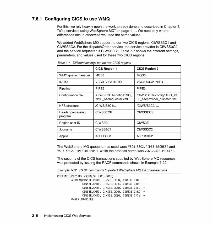
7.6.1 Configuring CICS to use WMQ
For this, we rely heavily upon the work already done and described in Chapter 4, “Web services using WebSphere MQ” on page 111. We note only where differences occur, otherwise we used the same values.
We added WebSphere MQ support to our two CICS regions, CIWSS3C1 and CIWSS3C2. For the dispatchOrder service, the service provider is CIWSS3C2 and the service requester is CIWSS3C1. Table 7-7 shows the different settings, parameters, and values used for these two CICS regions.
Table 7-7 Different settings for the two CICS regions
The WebSphere MQ queuenames used were VSG3.S3C2.PIPE3.REQUEST and VSG3.S3C2.PIPE3.RESPONSE while the process name was VSG3.S3C2.PROCESS.
The security of the CICS transactions supplied by WebSphere MQ resources was protected by issuing the RACF commands shown in Example 7-22.
Example 7-22 RACF commands to protect WebSphere MQ CICS transactions
RDEFINE GCICSTRN WS3MQUSR UACC(NONE) + ADDMEM(CIWS3E.CKBM, CIWS3E.CKCN, CIWS3E.CKDL, +
CIWS3E.CKDP, CIWS3E.CKQC, CIWS3E.CKRS, + CIWS3E.CKRT, CIWS3E.CKSD, CIWS3E.CKSQ, + CIWS3E.CKMC, CIWS3E.CKMH, CIWS3E.CKRC, + CIWS3E.CKRQ, CIWS3E.CKSG, CIWS3E.CKSV) +
OWNER(IBMUSER)
CICS Region 1 CICS Region 2
WMQ queue manager MQS3 MQS3
INITQ VSG3.S3C1.INITQ VSG3.S3C2.INITQ
Pipeline PIPE2 PIPE3
Configuration file /CIWS/S3C1/config/ITSO_7206_secrequester.xml
/CIWS/S3C2/config/ITSO_7206_secprovider_dispatch.xml
HFS structure /CIWS/S3C1/.... /CIWS/S3C2/....
Header processing program
CIWSSECR CIWSSECS
Region user ID CIWS3D CIWS3E
Jobname CIWSS3C1 CIWSS3C2
Applid A6POS3C1 A6POS3C2
216 Implementing CICS Web Services
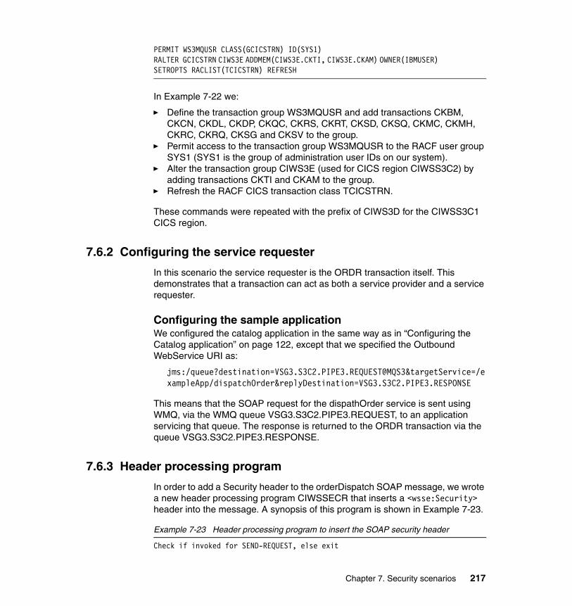
PERMIT WS3MQUSR CLASS(GCICSTRN) ID(SYS1) RALTER GCICSTRN CIWS3E ADDMEM(CIWS3E.CKTI, CIWS3E.CKAM) OWNER(IBMUSER) SETROPTS RACLIST(TCICSTRN) REFRESH
In Example 7-22 we:
� Define the transaction group WS3MQUSR and add transactions CKBM, CKCN, CKDL, CKDP, CKQC, CKRS, CKRT, CKSD, CKSQ, CKMC, CKMH, CKRC, CKRQ, CKSG and CKSV to the group.
� Permit access to the transaction group WS3MQUSR to the RACF user group SYS1 (SYS1 is the group of administration user IDs on our system).
� Alter the transaction group CIWS3E (used for CICS region CIWSS3C2) by adding transactions CKTI and CKAM to the group.
� Refresh the RACF CICS transaction class TCICSTRN.
These commands were repeated with the prefix of CIWS3D for the CIWSS3C1 CICS region.
7.6.2 Configuring the service requester
In this scenario the service requester is the ORDR transaction itself. This demonstrates that a transaction can act as both a service provider and a service requester.
Configuring the sample applicationWe configured the catalog application in the same way as in “Configuring the Catalog application” on page 122, except that we specified the Outbound WebService URI as:
jms:/queue?destination=VSG3.S3C2.PIPE3.REQUEST@MQS3&targetService=/exampleApp/dispatchOrder&replyDestination=VSG3.S3C2.PIPE3.RESPONSE
This means that the SOAP request for the dispathOrder service is sent using WMQ, via the WMQ queue VSG3.S3C2.PIPE3.REQUEST, to an application servicing that queue. The response is returned to the ORDR transaction via the queue VSG3.S3C2.PIPE3.RESPONSE.
7.6.3 Header processing program
In order to add a Security header to the orderDispatch SOAP message, we wrote a new header processing program CIWSSECR that inserts a <wsse:Security> header into the message. A synopsis of this program is shown in Example 7-23.
Example 7-23 Header processing program to insert the SOAP security header
Check if invoked for SEND-REQUEST, else exit
Chapter 7. Security scenarios 217
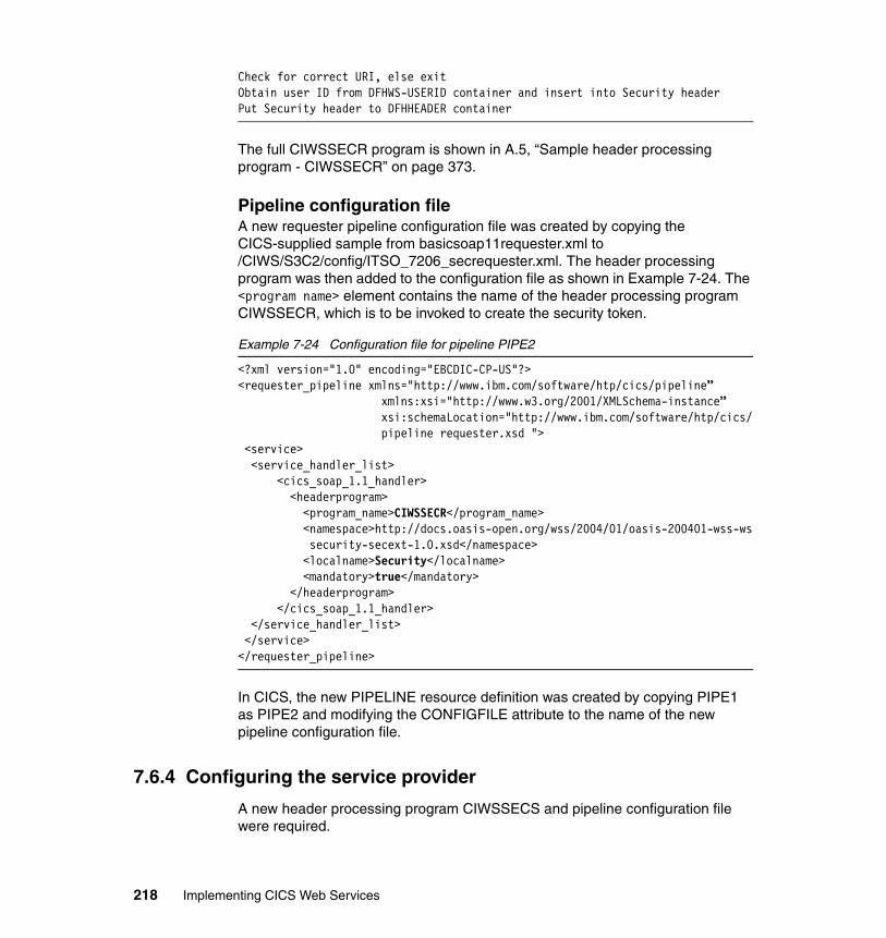
Check for correct URI, else exitObtain user ID from DFHWS-USERID container and insert into Security headerPut Security header to DFHHEADER container
The full CIWSSECR program is shown in A.5, “Sample header processing program - CIWSSECR” on page 373.
Pipeline configuration fileA new requester pipeline configuration file was created by copying the CICS-supplied sample from basicsoap11requester.xml to /CIWS/S3C2/config/ITSO_7206_secrequester.xml. The header processing program was then added to the configuration file as shown in Example 7-24. The <program name> element contains the name of the header processing program CIWSSECR, which is to be invoked to create the security token.
Example 7-24 Configuration file for pipeline PIPE2
<?xml version="1.0" encoding="EBCDIC-CP-US"?> <requester_pipeline xmlns="http://www.ibm.com/software/htp/cics/pipeline” xmlns:xsi="http://www.w3.org/2001/XMLSchema-instance”
xsi:schemaLocation="http://www.ibm.com/software/htp/cics/pipeline requester.xsd ">
<service> <service_handler_list> <cics_soap_1.1_handler> <headerprogram> <program_name>CIWSSECR</program_name>
<namespace>http://docs.oasis-open.org/wss/2004/01/oasis-200401-wss-wssecurity-secext-1.0.xsd</namespace>
<localname>Security</localname> <mandatory>true</mandatory> </headerprogram> </cics_soap_1.1_handler> </service_handler_list> </service> </requester_pipeline>
In CICS, the new PIPELINE resource definition was created by copying PIPE1 as PIPE2 and modifying the CONFIGFILE attribute to the name of the new pipeline configuration file.
7.6.4 Configuring the service provider
A new header processing program CIWSSECS and pipeline configuration file were required.
218 Implementing CICS Web Services
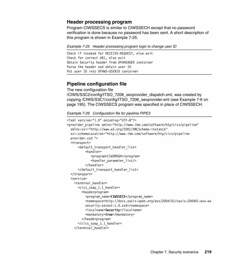
Header processing programProgram CIWSSECS is similar to CIWSSECH except that no password verification is done because no password has been sent. A short description of this program is shown in Example 7-25.
Example 7-25 Header processing program logic to change user ID
Check if invoked for RECEIVE-REQUEST, else exitCheck for correct URI, else exitObtain Security header from DFHHEADER containerParse the header and obtain user IDPut user ID into DFHWS-USERID container
Pipeline configuration fileThe new configuration file /CIWS/S3C2/config/ITSO_7206_secprovider_dispatch.xml, was created by copying /CIWS/S3C1/config/ITSO_7206_secprovider.xml (see Example 7-6 on page 195). The CIWSSECS program was specified in place of CIWSSECH.
Example 7-26 Configuration file for pipeline PIPE3
<?xml version="1.0" encoding="UTF-8"?> <provider_pipeline xmlns="http://www.ibm.com/software/htp/cics/pipeline" xmlns:xsi="http://www.w3.org/2001/XMLSchema-instance" xsi:schemaLocation="http://www.ibm.com/software/htp/cics/pipeline provider.xsd ">
<transport> <default_transport_handler_list> <handler> <program>CIWSMSGH</program> <handler_parameter_list/> </handler>
</default_transport_handler_list> </transport> <service> <terminal_handler> <cics_soap_1.1_handler> <headerprogram> <program_name>CIWSSECS</program_name>
<namespace>http://docs.oasis-open.org/wss/2004/01/oasis-200401-wss-wssecurity-secext-1.0.xsd</namespace>
<localname>Security</localname> <mandatory>true</mandatory> </headerprogram> </cics_soap_1.1_handler> </terminal_handler>
Chapter 7. Security scenarios 219
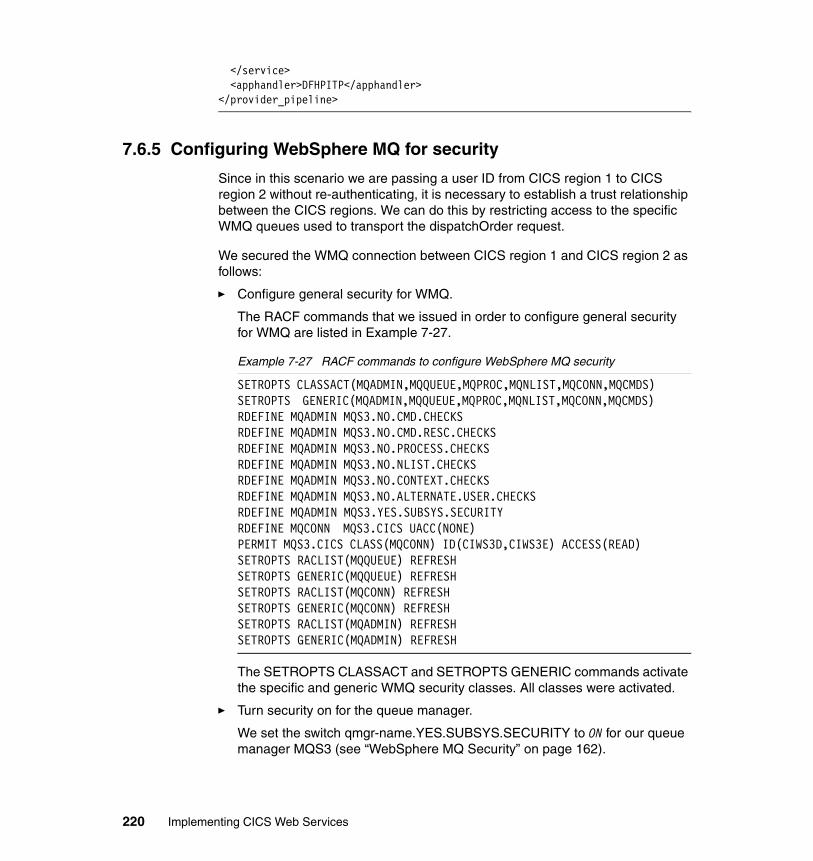
</service> <apphandler>DFHPITP</apphandler> </provider_pipeline>
7.6.5 Configuring WebSphere MQ for security
Since in this scenario we are passing a user ID from CICS region 1 to CICS region 2 without re-authenticating, it is necessary to establish a trust relationship between the CICS regions. We can do this by restricting access to the specific WMQ queues used to transport the dispatchOrder request.
We secured the WMQ connection between CICS region 1 and CICS region 2 as follows:
� Configure general security for WMQ.
The RACF commands that we issued in order to configure general security for WMQ are listed in Example 7-27.
Example 7-27 RACF commands to configure WebSphere MQ security
SETROPTS CLASSACT(MQADMIN,MQQUEUE,MQPROC,MQNLIST,MQCONN,MQCMDS) SETROPTS GENERIC(MQADMIN,MQQUEUE,MQPROC,MQNLIST,MQCONN,MQCMDS) RDEFINE MQADMIN MQS3.NO.CMD.CHECKS RDEFINE MQADMIN MQS3.NO.CMD.RESC.CHECKS RDEFINE MQADMIN MQS3.NO.PROCESS.CHECKS RDEFINE MQADMIN MQS3.NO.NLIST.CHECKS RDEFINE MQADMIN MQS3.NO.CONTEXT.CHECKS RDEFINE MQADMIN MQS3.NO.ALTERNATE.USER.CHECKS RDEFINE MQADMIN MQS3.YES.SUBSYS.SECURITY RDEFINE MQCONN MQS3.CICS UACC(NONE) PERMIT MQS3.CICS CLASS(MQCONN) ID(CIWS3D,CIWS3E) ACCESS(READ) SETROPTS RACLIST(MQQUEUE) REFRESH SETROPTS GENERIC(MQQUEUE) REFRESH SETROPTS RACLIST(MQCONN) REFRESH SETROPTS GENERIC(MQCONN) REFRESH SETROPTS RACLIST(MQADMIN) REFRESH SETROPTS GENERIC(MQADMIN) REFRESH
The SETROPTS CLASSACT and SETROPTS GENERIC commands activate the specific and generic WMQ security classes. All classes were activated.
� Turn security on for the queue manager.
We set the switch qmgr-name.YES.SUBSYS.SECURITY to ON for our queue manager MQS3 (see “WebSphere MQ Security” on page 162).
220 Implementing CICS Web Services
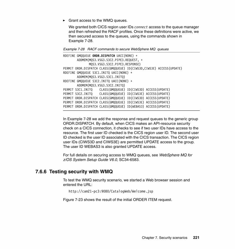
� Grant access to the WMQ queues.
We granted both CICS region user IDs connect access to the queue manager and then refreshed the RACF profiles. Once these definitions were active, we then secured access to the queues, using the commands shown in Example 7-28.
Example 7-28 RACF commands to secure WebSphere MQ queues
RDEFINE GMQQUEUE ORDR.DISPATCH UACC(NONE) + ADDMEM(MQS3.VSG3.S3C2.PIPE3.REQUEST, + MQS3.VSG3.S3C2.PIPE3.RESPONSE) PERMIT ORDR.DISPATCH CLASS(GMQQUEUE) ID(CIWS3D,CIWS3E) ACCESS(UPDATE)RDEFINE GMQQUEUE S3C1.INITQ UACC(NONE) + ADDMEM(MQS3.VSG3.S3C1.INITQ) RDEFINE GMQQUEUE S3C2.INITQ UACC(NONE) + ADDMEM(MQS3.VSG3.S3C2.INITQ) PERMIT S3C1.INITQ CLASS(GMQQUEUE) ID(CIWS3D) ACCESS(UPDATE) PERMIT S3C2.INITQ CLASS(GMQQUEUE) ID(CIWS3E) ACCESS(UPDATE) PERMIT ORDR.DISPATCH CLASS(GMQQUEUE) ID(CIWS3D) ACCESS(UPDATE) PERMIT ORDR.DISPATCH CLASS(GMQQUEUE) ID(CIWS3E) ACCESS(UPDATE)PERMIT ORDR.DISPATCH CLASS(GMQQUEUE) ID(WEBAS3) ACCESS(UPDATE)
In Example 7-28 we add the response and request queues to the generic group ORDR.DISPATCH. By default, when CICS makes an API-resource security check on a CICS connection, it checks to see if two user IDs have access to the resource. The first user ID checked is the CICS region user ID. The second user ID checked is the user ID associated with the CICS transaction. The CICS region user IDs (CIWS3D and CIWS3E) are permitted UPDATE access to the group. The user ID WEBAS3 is also granted UPDATE access.
For full details on securing access to WMQ queues, see WebSphere MQ for z/OS System Setup Guide V6.0, SC34-6583.
7.6.6 Testing security with WMQ
To test the WMQ security scenario, we started a Web browser session and entered the URL:
http://cam21-pc3:9080/CatalogWeb/Welcome.jsp
Figure 7-23 shows the result of the initial ORDER ITEM request.
Chapter 7. Security scenarios 221
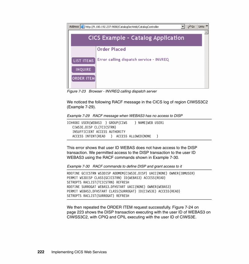
Figure 7-23 Browser - INVREQ calling dispatch server
We noticed the following RACF message in the CICS log of region CIWSS3C2 (Example 7-29).
Example 7-29 RACF message when WEBAS3 has no access to DISP
ICH408I USER(WEBAS3 ) GROUP(CIWS ) NAME(WEB USER1 CIWS3E.DISP CL(TCICSTRN) INSUFFICIENT ACCESS AUTHORITY ACCESS INTENT(READ ) ACCESS ALLOWED(NONE )
This error shows that user ID WEBAS does not have access to the DISP transaction. We permitted access to the DISP transaction to the user ID WEBAS3 using the RACF commands shown in Example 7-30.
Example 7-30 RACF commands to define DISP and grant access to it
RDEFINE GCICSTRN WS3DISP ADDMEM(CIWS3E.DISP) UACC(NONE) OWNER(IBMUSER) PERMIT WS3DISP CLASS(GCICSTRN) ID(WEBAS3) ACCESS(READ) SETROPTS RACLIST(TCICSTRN) REFRESH RDEFINE SURROGAT WEBAS3.DFHSTART UACC(NONE) OWNER(WEBAS3) PERMIT WEBAS3.DFHSTART CLASS(SURROGAT) ID(CIWS3E) ACCESS(READ) SETROPTS RACLIST(SURROGAT) REFRESH
We then repeated the ORDER ITEM request successfully. Figure 7-24 on page 223 shows the DISP transaction executing with the user ID of WEBAS3 on CIWSS3C2, with CPIQ and CPIL executing with the user ID of CIWS3E.
222 Implementing CICS Web Services
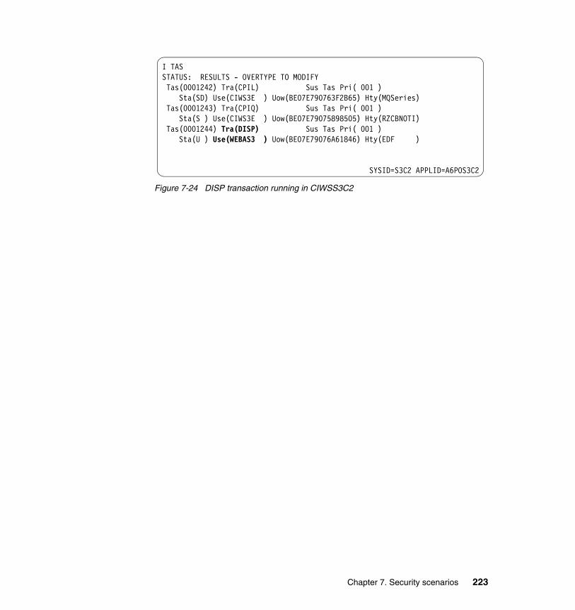
Figure 7-24 DISP transaction running in CIWSS3C2
I TAS STATUS: RESULTS - OVERTYPE TO MODIFY Tas(0001242) Tra(CPIL) Sus Tas Pri( 001 )
Sta(SD) Use(CIWS3E ) Uow(BE07E790763F2B65) Hty(MQSeries) Tas(0001243) Tra(CPIQ) Sus Tas Pri( 001 ) Sta(S ) Use(CIWS3E ) Uow(BE07E79075898505) Hty(RZCBNOTI) Tas(0001244) Tra(DISP) Sus Tas Pri( 001 ) Sta(U ) Use(WEBAS3 ) Uow(BE07E79076A61846) Hty(EDF )
SYSID=S3C2 APPLID=A6POS3C2
Chapter 7. Security scenarios 223

224 Implementing CICS Web Services
Part 4 Transaction management
In this part, we begin by providing an introduction to Web services atomic transactions. We then outline the steps for enabling WS-Atomic Transaction (WS-AT) support in CICS. Finally, we show several scenarios that demonstrate how you can synchronize WebSphere and CICS updates using the WS-AT standard.
Part 4
© Copyright IBM Corp. 2006. All rights reserved. 225

226 Implementing CICS Web Services
Chapter 8. Introduction to Web services: Atomic transactions
We begin this chapter by describing an example of a classic transaction. We expect that most of our readers will be familiar with examples similar to ours. Then we map our classical transaction to a Web services atomic transaction as a means of introducing the new terminology that we use in this and succeeding chapters: coordinator, transactional context, activation service, registration service, and completion protocol. We continue by providing an overview of the flows and message contents prescribed by the three specifications upon which CICS TS V3.1 support for atomic transactions is built:
� Web Services - Addressing (WS-Addressing or WS-A)
� Web Services - Coordination (WS-Coordination or WS-C)
� Web Services - Atomic Transaction (WS-Atomic Transaction or WS-AT)
8
© Copyright IBM Corp. 2006. All rights reserved. 227
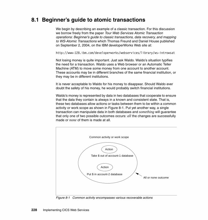
8.1 Beginner’s guide to atomic transactions
We begin by describing an example of a classic transaction. For this discussion we borrow freely from the paper Tour Web Services Atomic Transaction operations: Beginner’s guide to classic transactions, data recovery, and mapping to WS-Atomic Transactions which Thomas Freund and Daniel House published on September 2, 2004, on the IBM developerWorks Web site at:
http://www-128.ibm.com/developerworks/webservices/library/ws-introwsat
Not losing money is quite important. Just ask Waldo. Waldo’s situation typifies the need for a transaction. Waldo uses a Web browser or an Automatic Teller Machine (ATM) to move some money from one account to another account. These accounts may be in different branches of the same financial institution, or they may be in different institutions.
It is never acceptable to Waldo for his money to disappear. Should Waldo ever doubt the safety of his money, he would probably switch financial institutions.
Waldo’s money is represented by data in two databases that cooperate to ensure that the data they contain is always in a known and consistent state. That is, these two databases allow actions or tasks between them to be within a common activity or work scope as shown in Figure 8-1. Put yet another way, a single transaction can manipulate data in both databases and something will guarantee that only one of two possible outcomes occurs: all the changes are successfully made or none of them is made at all.
Figure 8-1 Common activity encompasses various recoverable actions
Common activity or work scope
Action
Put $ in account-2 database
Action
All or none outcome
Take $ out of account-1 database
228 Implementing CICS Web Services
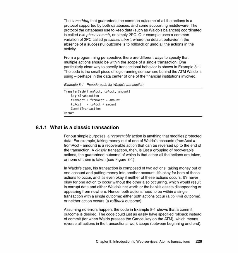
The something that guarantees the common outcome of all the actions is a protocol supported by both databases, and some supporting middleware. The protocol the databases use to keep data (such as Waldo’s balances) coordinated is called two phase commit, or simply 2PC. Our example uses a common variation of 2PC called presumed abort, where the default behavior in the absence of a successful outcome is to rollback or undo all the actions in the activity.
From a programming perspective, there are different ways to specify that multiple actions should be within the scope of a single transaction. One particularly clear way to specify transactional behavior is shown in Example 8-1. The code is the small piece of logic running somewhere behind the ATM Waldo is using – perhaps in the data center of one of the financial institutions involved.
Example 8-1 Pseudo-code for Waldo’s transaction
TransferCash(fromAcct, toAcct, amount) BeginTransaction fromAcct = fromAcct - amount toAcct = toAcct + amount CommitTransactionReturn
8.1.1 What is a classic transaction
For our simple purposes, a recoverable action is anything that modifies protected data. For example, taking money out of one of Waldo’s accounts (fromAcct = fromAcct - amount) is a recoverable action that can be reversed up to the end of the transaction. A classic transaction, then, is just a grouping of recoverable actions, the guaranteed outcome of which is that either all the actions are taken, or none of them is taken (see Figure 8-1).
In Waldo’s case, his transaction is composed of two actions: taking money out of one account and putting money into another account. It’s okay for both of these actions to occur, and it’s even okay if neither of these actions occurs. It’s never okay for one action to occur without the other also occurring, which would result in corrupt data and either Waldo’s net worth or the bank’s assets disappearing or appearing from nowhere. Hence, both actions need to be within a single transaction with a single outcome: either both actions occur (a commit outcome), or neither action occurs (a rollback outcome).
Assuming no errors happen, the code in Example 8-1 shows that a commit outcome is desired. The code could just as easily have specified rollback instead of commit (for when Waldo presses the Cancel key on the ATM), which means reverse all actions in the transactional work scope (between beginning and end).
Chapter 8. Introduction to Web services: Atomic transactions 229
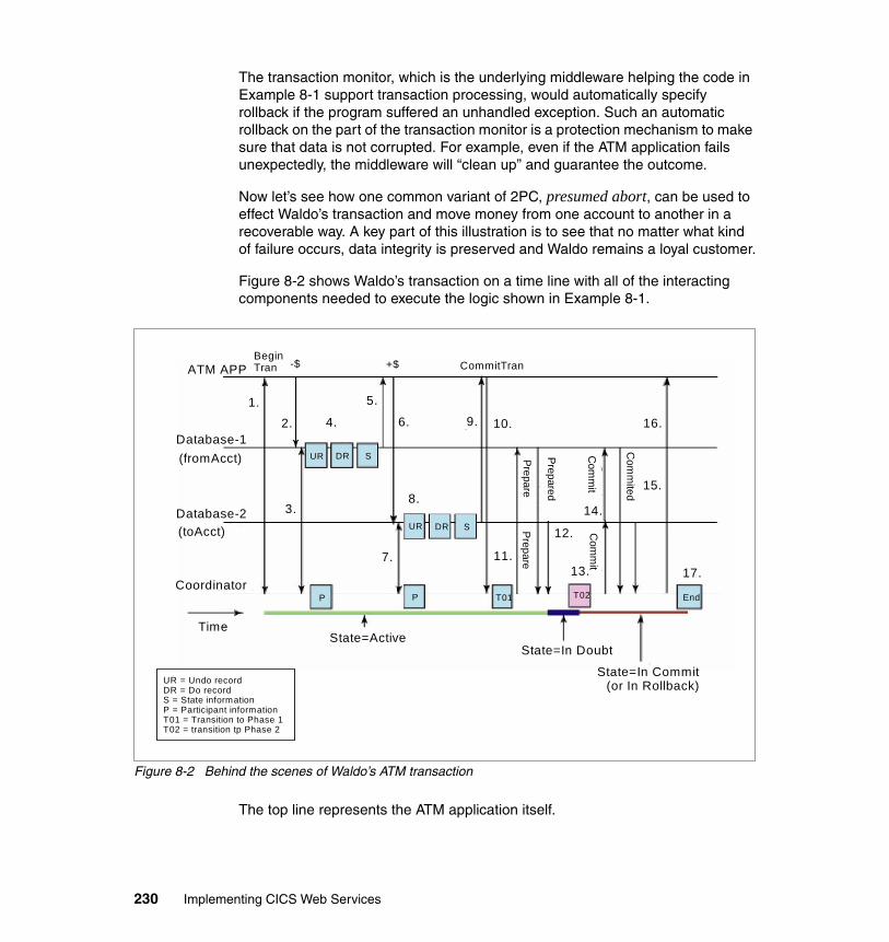
The transaction monitor, which is the underlying middleware helping the code in Example 8-1 support transaction processing, would automatically specify rollback if the program suffered an unhandled exception. Such an automatic rollback on the part of the transaction monitor is a protection mechanism to make sure that data is not corrupted. For example, even if the ATM application fails unexpectedly, the middleware will “clean up” and guarantee the outcome.
Now let’s see how one common variant of 2PC, presumed abort, can be used to effect Waldo’s transaction and move money from one account to another in a recoverable way. A key part of this illustration is to see that no matter what kind of failure occurs, data integrity is preserved and Waldo remains a loyal customer.
Figure 8-2 shows Waldo’s transaction on a time line with all of the interacting components needed to execute the logic shown in Example 8-1.
Figure 8-2 Behind the scenes of Waldo’s ATM transaction
The top line represents the ATM application itself.
ATM APPBeginTran
Database-1(fromAcct)
Database-2(toAcct)
Coordinator
Time
CommitTran
1.2.
3.
4. 6. 9. 10. 16.
5.
8.
7. 11.
12.
13. 17.
15.
UR DR S
P P T01 T02 End
UR DR S
State=ActiveState=In Doubt
State=In Commit(or In Rollback)
PrepareP
repare
Prepared
Com
mit
14.
Com
mit
Com
mited
-$ +$
UR = Undo recordDR = Do recordS = State informationP = Participant informationT01 = Transition to Phase 1T02 = transition tp Phase 2
230 Implementing CICS Web Services
The next two lines represent the account databases that the application manipulates. The databases will be transactional participants.
The next line is a transactional coordinator, or middleware, which will orchestrate the 2PC protocol.
The line at the very bottom indicates the state of Waldo’s transaction at different points in time. The state of the transaction dictates recovery processing in the event of a failure.
The lines for Database-1, Database-2, and Coordinator represent both time (flowing left to right) and also some key records recorded onto a recovery log. These records include images of the data before it is modified (Undo records), images of the data after it has been modified (Do records), and state information. The recovery log is used to insure data integrity during recovery processing.
Now let’s walk through Waldo’s transaction. In the following discussion, when we talk about the ATM application, take it to mean either the application itself, or some middleware supporting the application. For example, when we say the application begins a transactional scope, it could be that middleware begins the transactional scope on behalf of the application.
Here is narration to explain the numbered steps shown in Figure 8-2:
1. The ATM application indicates the beginning of a transactional scope. The Coordinator creates a context for this transaction; the context includes a unique identifier and some other information about the transaction. Importantly, this transaction context flows back to the application. The context flows with other interactions between the application and resource managers; it is the context that helps glue together a whole set of actions into one transactional activity.
2. The application takes money out of Database-1. The context (from step 1) is inserted into this flow.
3. Database-1 sees the request for action, but also sees the transactional context. Database-1 uses this context to contact the transactional Coordinator and register interest in this transaction or activity (so that the Coordinator will help Database-1 through 2PC processing later to guarantee a commit or rollback outcome of all actions). The Coordinator remembers that Database-1 is a participant in the transaction.
4. Database-1 looks at the request to modify recoverable data. It writes records to a recovery log, plus transaction state information. One record describes the database change to be made if the decision later is to commit (the Do record). The other record describes the database change to be made if the decision is to rollback (the Undo record).
Chapter 8. Introduction to Web services: Atomic transactions 231
– In this case, the Undo record says make Waldo’s balance = x and the Do record says make Waldo’s balance = x - $. (X is the amount of the balance before this transaction ever started and $ is the amount to transfer). Notice that we are only looking at the recovery log – not database files.
– The Do records are not strictly required if Database-1 makes database file updates when the application requests it to, instead of waiting. However, waiting to write the data can have advantages for performance and concurrency. In addition, the Do records may be used for audit or other advanced reasons. Since they are so useful, our example databases use them.
5. Return to the application.
6. Similarly to step 2, the application makes a request to manipulate the other database, Database-2. The application wants to add in the amount taken out of Database-1.
7. Database-2 registers interest in the transaction with the Coordinator the same way Database-1 did. The Coordinator remembers that Database-2 is a participant in the transaction.
8. Database-2 writes Undo and Do records and state information to its recovery log, again just as Database-1 did.
9. Return to the application.
10.The application chooses to commit the transaction. The Coordinator now takes over. When Commit is received, the Coordinator writes a log record indicating that Phase 1 of 2PC has begun.
11.In Phase 1, the Coordinator goes down the list of all participants (Database-1 and Database-2 in this example) who expressed interest in this transaction, asking each one to Prepare. Prepare means get ready to receive the order to either commit or rollback.
12.Database-1 and Database-2 both respond with Prepared, meaning that they are ready to be told the final outcome (commit or rollback all the changes made) and support it.
– They must have committed something (at least on their logs) by this point, because responding Prepared means they guarantee being able to commit or rollback when told - actions up to this point were just tentative.
– If either Database had some kind of failure preparing, it would respond Aborted instead of Prepared, and the Coordinator would broadcast Rollback to all participants.
13.The Coordinator forces a log record indicating a Transition to Phase 2 (T02).
– Once this record is hardened on a log, we know and have recorded that:
• All participants are prepared to go either way (commit or rollback).
232 Implementing CICS Web Services
• The ultimate outcome of the transaction is known (commit in our example).
• The outcome is guaranteed by recovery processing.
– If this record fails to make it to the log for any reason, the ultimate outcome will be to rollback (we are using presumed abort in this example). The recovery processing will enforce the outcome.
14.The Coordinator informs each participant that the decision is to commit the changes. The participants can then do whatever they need to do, such as perhaps writing the results to the real database data.
15.The participants return to the Coordinator with Committed. Once the Coordinator knows that all the participants acknowledged the Commit order with Committed, it can forget about this transaction because the transaction was acknowledged by all to be done.
16.Return to the application.
17.At some point, since it knows the participants have succeeded in the 2PC flow by acknowledging the common outcome, the Coordinator writes an End indicator on its log.
8.1.2 Mapping from classic transactions to WS-Atomic Transaction
In Figure 8-2 on page 230 we did not mention how Database-1 contacted the Coordinator, nor did we specify how the application called the databases. In fact, we didn’t specify the mechanisms for anything to contact anything else. In the past, these were mostly non-universal mechanisms that sometimes only worked between certain combinations of entities (applications, resource managers, and coordinators or transaction monitors).
The combination of Web services, WS-Coordination (WS-C) and WS-Atomic Transaction (WS-AT) maps all of the flows shown in Figure 8-2 on page 230 and specifies precise communications mechanisms for achieving the same results. However, instead of only working between certain combinations, the Web services based flows can work with just about anything.
Figure 8-3 illustrates how the classic flows are converted to Web services. Significantly changed steps are described following the figure. As before, when we say application, take it to mean the application or some helper middleware. Likewise, when we say database, it might mean the actual database, or some helper middleware.
Chapter 8. Introduction to Web services: Atomic transactions 233
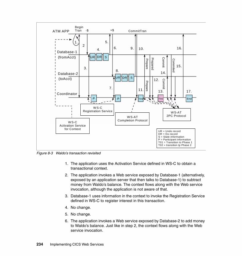
Figure 8-3 Waldo’s transaction revisited
1. The application uses the Activation Service defined in WS-C to obtain a transactional context.
2. The application invokes a Web service exposed by Database-1 (alternatively, exposed by an application server that then talks to Database-1) to subtract money from Waldo’s balance. The context flows along with the Web service invocation, although the application is not aware of that.
3. Database-1 uses information in the context to invoke the Registration Service defined in WS-C to register interest in this transaction.
4. No change.
5. No change.
6. The application invokes a Web service exposed by Database-2 to add money to Waldo’s balance. Just like in step 2, the context flows along with the Web service invocation.
ATM APPBeginTran
Database-1(fromAcct)
Database-2(toAcct)
Coordinator
CommitTran
1.2
3.
4.
5.6. 9.
8.
7.
10.
11.
12.
13.
14.
15.
16.
17.
P P T01 T02 End
UR
UR DR S
DR S
WS-CActivation Service
for Context
W S-CRegistration Service
WS-ATCompletion Protocol
WS-AT2PC Protocol
PreparePrepare
Prepared
Com
mit
Com
mit
Com
mited
-$ +$
UR = Undo recordDR = Do recordS = State informationP = Participant informationT01 = Transition to Phase 1T02 = transition tp Phase 2
234 Implementing CICS Web Services
7. Just like step 3, Database-2 uses information in the context to invoke the Registration Service and register interest in this transaction.
8. No change.
9. No change.
10.The application uses the Completion Protocol defined in WS-AT to indicate that it wishes to commit the transaction.
11.to 15. Databases and the Coordinator participate in 2PC flows as defined in the WS-AT 2PC Protocol.
From Figure 8-3 it is clear that atomic transactions using Web services (WS-C and WS-AT) are substantially the same as without Web services (Figure 8-2 on page 230, for example). The primary differences are almost cosmetic from the outside and involve how entities communicate with each other, not the substance of what they communicate. However, these differences in how the entities communicate have a big impact on flexibility and interoperability.
You can achieve universal interoperability with Web services because instead of changing resource manager X to interoperate with transaction monitor Y, you can change both X and Y to use Web services and then interoperate with many other resource managers and transaction monitors. So instead of two-at-a-time interoperability, or interoperability only within a specific kind of domain, n-way universal interoperability is possible.
Recovery processing using Web services between the interested parties is the same as before Web services. Resource managers are the only ones who know their resources and how to commit them or roll them back.
As an example, suppose that Database-1 fails between steps 5 and 6 in Figure 8-3. Database-1 comes back up and, just like before Web services, it reads its log, notices that it has an incomplete transaction, and realizes that it needs to contact the Coordinator. Information on how to contact the Coordinator is in the state saved on its recovery log; with Web services it will be an end point reference (as defined in WS-Addressing; see “Endpoint references” on page 237). Database-1 contacts the Coordinator at that end point reference with a message defined in WS-AT called Replay. Replay causes the Coordinator to resend the last protocol message to Database-1, which lets Database-1 deduce the transaction state and then apply the appropriate recovery rule. In our example the Coordinator tells Database-1 that it has no knowledge of this transaction. Database-1 therefore applies its Undo record, making the data consistent again.
Chapter 8. Introduction to Web services: Atomic transactions 235
8.2 WS-Addressing
Figure 8-3 on page 234 shows several messages flowing:
� The application sends a message to the Activation Service asking for a transactional context.
� The Activation Service sends a response containing a transactional context to the application.
� Database-1 and Database-2 each send a Register message to the Registration Service and receives a reply.
� The application sends a Commit message to the Coordinator.
� The Coordinator sends Prepare and Commit messages to Database-1 and Database-2.
� Database-1 and Database-2 each send Prepared and Committed messages to the Coordinator.
The application, Database-1, Database-2, the Activation Service, the Registration Service, and the Coordinator are endpoints for these messages. As with messages in the everyday business world, we need a way to identify the recipient of each message, the sender of the message, what previous message (if any) the message relates to, what action we want the recipient to take, and where the recipient should send the reply (if any) to the message. Furthermore, we want to be able to do this in a way that does not depend on the transport mechanism (such as HTTP or WebSphere MQ) that we use to send the message.
To this end IBM, Microsoft, Sun™ Microsystems™, BEA, and SAP formally submitted the Web Services- Addressing (WS - Addressing) specification to the World Wide Web Consortium (W3C) on 10 August 2004. You can find this specification at:
http://www.w3.org/Submission/ws-addressing
Important: WS-AT is a two-phase commit transaction protocol that is suitable for short duration transactions only. WS-AT is well suited for distributed transactions within a single enterprise, but is it is generally not recommended that WS-AT transactions be distributed across enterprise domains. Inter-enterprise transactions typically require a looser semantic than two-phase commit.
236 Implementing CICS Web Services
All information items defined by the 10 August 2004 specification are identified by the XML namespace URI:
http://schemas.xmlsoap.org/ws/2004/08/addressing
We associate the namespace prefix wsa with this namespace by using the attribute
xmlns:wsa="http://schemas.xmlsoap.org/ws/2004/08/addressing"
The specification defines two constructs:
� Endpoint references
� Message information headers
8.2.1 Endpoint references
A Web service endpoint is a (referenceable) entity, processor, or resource to which Web services messages can be addressed.
An endpoint reference conveys the information needed to address a Web service endpoint. As we shall see later:
� An endpoint reference for the Registration Service forms part of the coordination context.
� An endpoint reference for the participant’s Protocol Service forms part of the Register request.
Note: As the specification has moved through the W3C standards process, it has been divided into three parts:
� Web Services Addressing 1.0 - Core
This is currently a W3C Candidate Recommendation dated 17 August 2005.
� Web Services Addressing 1.0 - SOAP Binding
This is also currently a W3C Candidate Recommendation dated 17 August 2005.
� Web Services Addressing 1.0 - WSDL Binding
This is currently a W3C Working Draft dated 13 April 2005.
However, the WS-Coordination and WS-Atomic Transaction specifications that we discuss later in this chapter are based on the 10 August 2004 specification, and, therefore, so is CICS TS V3.1 support for Web services.
Chapter 8. Introduction to Web services: Atomic transactions 237
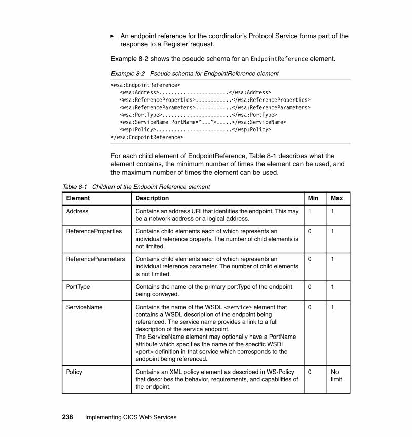
� An endpoint reference for the coordinator’s Protocol Service forms part of the response to a Register request.
Example 8-2 shows the pseudo schema for an EndpointReference element.
Example 8-2 Pseudo schema for EndpointReference element
<wsa:EndpointReference> <wsa:Address>.......................</wsa:Address> <wsa:ReferenceProperties>............</wsa:ReferenceProperties> <wsa:ReferenceParameters>............</wsa:ReferenceParameters> <wsa:PortType>.......................</wsa:PortType> <wsa:ServiceName PortName=“...”>.....</wsa:ServiceName> <wsp:Policy>.........................</wsp:Policy> </wsa:EndpointReference>
For each child element of EndpointReference, Table 8-1 describes what the element contains, the minimum number of times the element can be used, and the maximum number of times the element can be used.
Table 8-1 Children of the Endpoint Reference element
Element Description Min Max
Address Contains an address URI that identifies the endpoint. This may be a network address or a logical address.
1 1
ReferenceProperties Contains child elements each of which represents an individual reference property. The number of child elements is not limited.
0 1
ReferenceParameters Contains child elements each of which represents an individual reference parameter. The number of child elements is not limited.
0 1
PortType Contains the name of the primary portType of the endpoint being conveyed.
0 1
ServiceName Contains the name of the WSDL <service> element that contains a WSDL description of the endpoint being referenced. The service name provides a link to a full description of the service endpoint.The ServiceName element may optionally have a PortName attribute which specifies the name of the specific WSDL <port> definition in that service which corresponds to the endpoint being referenced.
0 1
Policy Contains an XML policy element as described in WS-Policy that describes the behavior, requirements, and capabilities of the endpoint.
0 No limit
238 Implementing CICS Web Services
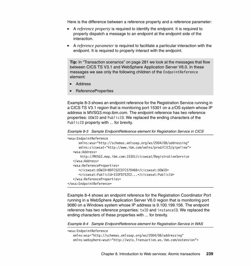
Here is the difference between a reference property and a reference parameter:
� A reference property is required to identify the endpoint. It is required to properly dispatch a message to an endpoint at the endpoint side of the interaction.
� A reference parameter is required to facilitate a particular interaction with the endpoint. It is required to properly interact with the endpoint.
Example 8-3 shows an endpoint reference for the Registration Service running in a CICS TS V3.1 region that is monitoring port 15301 on a z/OS system whose IP address is MVSG3.mop.ibm.com. The endpoint reference has two reference properties: UOWID and PublicID. We replaced the ending characters of the PublicID property with ... for brevity.
Example 8-3 Sample EndpointReference element for Registration Service in CICS
<wsa:EndpointReference xmlns:wsa="http://schemas.xmlsoap.org/ws/2004/08/addressing" xmlns:cicswsat="http://www.ibm.com/xmlns/prod/CICS/pipeline"> <wsa:Address> http://MVSG3.mop.ibm.com:15301/cicswsat/RegistrationService </wsa:Address> <wsa:ReferenceProperties> <cicswsat:UOWID>BDFC52CD7C57D466</cicswsat:UOWID> <cicswsat:PublicId>310FD7E2E2...</cicswsat:PublicId> </wsa:ReferenceProperties> </wsa:EndpointReference>
Example 8-4 shows an endpoint reference for the Registration Coordinator Port running in a WebSphere Application Server V6.0 region that is monitoring port 9080 on a Windows system whose IP address is 9.100.199.156. The endpoint reference has two reference properties: txID and instanceID. We replaced the ending characters of these properties with ... for brevity.
Example 8-4 Sample EndpointReference element for Registration Service in WAS
<wsa:EndpointReference xmlns:wsa="http://schemas.xmlsoap.org/ws/2004/08/addressing" xmlns:websphere-wsat="http://wstx.Transaction.ws.ibm.com/extension">
Tip: In “Transaction scenarios” on page 281 we look at the messages that flow between CICS TS V3.1 and WebSphere Application Server V6.0. In these messages we see only the following children of the EndpointReference element:
� Address
� ReferenceProperties
Chapter 8. Introduction to Web services: Atomic transactions 239

<wsa:Address> http://9.100.199.156:9080/_IBMSYSAPP/wscoor/services/Registration CoordinatorPort </wsa:Address> <wsa:ReferenceProperties> <websphere-wsat:txID> com.ibm.ws.wstx:00000107d70ad26c0000000700000005cbb17a7d5f7e... </websphere-wsat:txID> <websphere-wsat:instanceID> com.ibm.ws.wstx:00000107d70ad26c0000000700000005cbb17a7d5f7e... </websphere-wsat:instanceID> </wsa:ReferenceProperties></wsa:EndpointReference>
8.2.2 Message information headers
Example 8-5 shows pseudo schema for the message information headers defined in the WS-Addressing specification.
Example 8-5 Pseudo schema for message information header elements
<wsa:MessageID>..........................</wsa:MessageID><wsa:RelatesTo RelationshipType="...">...</wsa:RelatesTo> <wsa:To>.................................</wsa:To><wsa:Action>.............................</wsa:Action><wsa:From>..............................</wsa:From><wsa:ReplyTo>............................</wsa:ReplyTo><wsa:FaultTo>............................</wsa:FaultTo>
Table 8-2 describes what each message information header element contains, the minimum number of times the element may be used, and the maximum number of times the element may be used.
Table 8-2 Message information header elements
Element Description Min Max
MessageID Contains a URI that uniquely identifies this message in space and time.
0 (but see Note 1)
1
RelatesTo Contains a URI that corresponds to a related message’s MessageID property.The RelatesTo element has an optional RelationshipType attribute that indicate the type of relationship this message has to the related message.The specification defines one relationship type, namely wsa:Reply.When absent, the implied value of this attribute is wsa:Reply.
0 No limit
240 Implementing CICS Web Services
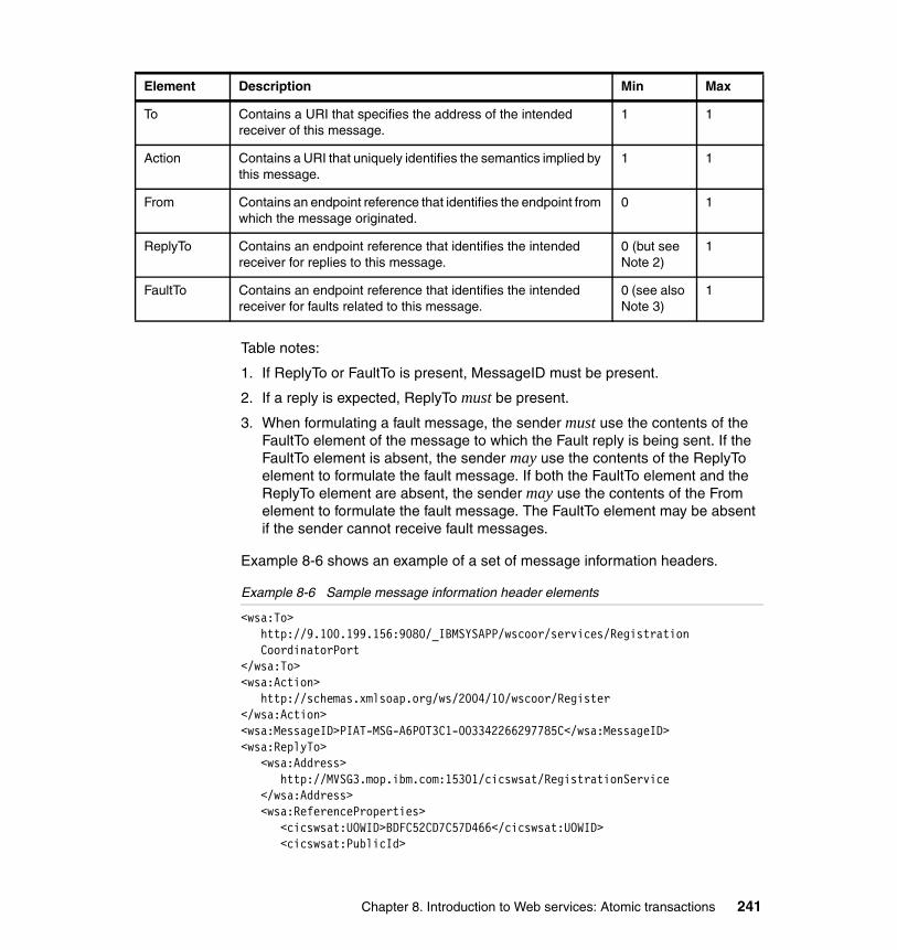
Table notes:
1. If ReplyTo or FaultTo is present, MessageID must be present.
2. If a reply is expected, ReplyTo must be present.
3. When formulating a fault message, the sender must use the contents of the FaultTo element of the message to which the Fault reply is being sent. If the FaultTo element is absent, the sender may use the contents of the ReplyTo element to formulate the fault message. If both the FaultTo element and the ReplyTo element are absent, the sender may use the contents of the From element to formulate the fault message. The FaultTo element may be absent if the sender cannot receive fault messages.
Example 8-6 shows an example of a set of message information headers.
Example 8-6 Sample message information header elements
<wsa:To> http://9.100.199.156:9080/_IBMSYSAPP/wscoor/services/Registration CoordinatorPort</wsa:To><wsa:Action> http://schemas.xmlsoap.org/ws/2004/10/wscoor/Register</wsa:Action><wsa:MessageID>PIAT-MSG-A6POT3C1-003342266297785C</wsa:MessageID><wsa:ReplyTo> <wsa:Address> http://MVSG3.mop.ibm.com:15301/cicswsat/RegistrationService </wsa:Address> <wsa:ReferenceProperties> <cicswsat:UOWID>BDFC52CD7C57D466</cicswsat:UOWID> <cicswsat:PublicId>
To Contains a URI that specifies the address of the intended receiver of this message.
1 1
Action Contains a URI that uniquely identifies the semantics implied by this message.
1 1
From Contains an endpoint reference that identifies the endpoint from which the message originated.
0 1
ReplyTo Contains an endpoint reference that identifies the intended receiver for replies to this message.
0 (but see Note 2)
1
FaultTo Contains an endpoint reference that identifies the intended receiver for faults related to this message.
0 (see also Note 3)
1
Element Description Min Max
Chapter 8. Introduction to Web services: Atomic transactions 241
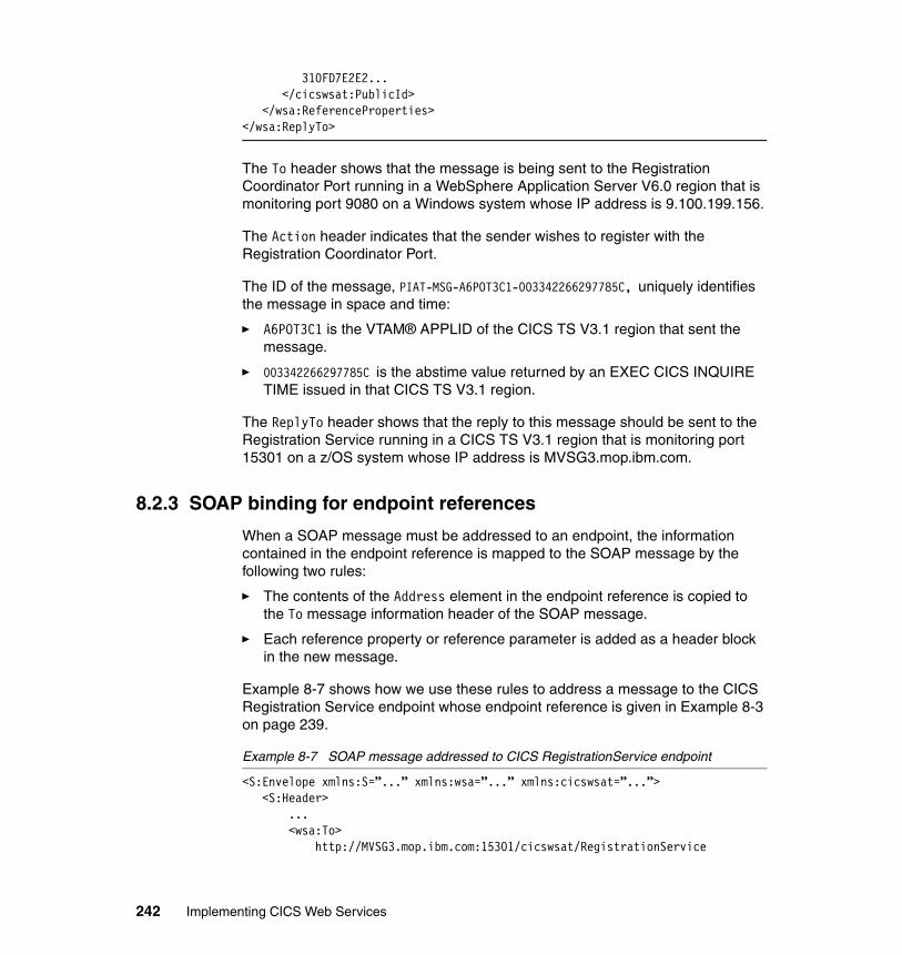
310FD7E2E2... </cicswsat:PublicId> </wsa:ReferenceProperties></wsa:ReplyTo>
The To header shows that the message is being sent to the Registration Coordinator Port running in a WebSphere Application Server V6.0 region that is monitoring port 9080 on a Windows system whose IP address is 9.100.199.156.
The Action header indicates that the sender wishes to register with the Registration Coordinator Port.
The ID of the message, PIAT-MSG-A6POT3C1-003342266297785C, uniquely identifies the message in space and time:
� A6POT3C1 is the VTAM® APPLID of the CICS TS V3.1 region that sent the message.
� 003342266297785C is the abstime value returned by an EXEC CICS INQUIRE TIME issued in that CICS TS V3.1 region.
The ReplyTo header shows that the reply to this message should be sent to the Registration Service running in a CICS TS V3.1 region that is monitoring port 15301 on a z/OS system whose IP address is MVSG3.mop.ibm.com.
8.2.3 SOAP binding for endpoint references
When a SOAP message must be addressed to an endpoint, the information contained in the endpoint reference is mapped to the SOAP message by the following two rules:
� The contents of the Address element in the endpoint reference is copied to the To message information header of the SOAP message.
� Each reference property or reference parameter is added as a header block in the new message.
Example 8-7 shows how we use these rules to address a message to the CICS Registration Service endpoint whose endpoint reference is given in Example 8-3 on page 239.
Example 8-7 SOAP message addressed to CICS RegistrationService endpoint
<S:Envelope xmlns:S=”...” xmlns:wsa=”...” xmlns:cicswsat=”...”> <S:Header>
...<wsa:To>
http://MVSG3.mop.ibm.com:15301/cicswsat/RegistrationService
242 Implementing CICS Web Services
</wsa:To> <cicswsat:UOWID>BDFC52CD7C57D466</cicswsat:UOWID> <cicswsat:PublicId>310FD7E2E2...</cicswsat:PublicId>...
</S:Header><S:Body>
...</S:Body>
</S:Envelope>
8.3 WS-Coordination
In “Beginner’s guide to atomic transactions” on page 228 and “WS-Addressing” on page 236 we see that the application, Database-1, Database-2, the Activation service, the Registration service, and the Coordinator are endpoints for messages. We also see that:
� The application sends a message to the Activation service asking for a transactional context.
� The Activation service sends a response containing a transactional context to the application.
� Database-1 and Database-2 each sends a Register message to the Registration service and receives a reply.
We still need to define what these messages should contain.
For this purpose IBM, Microsoft, and BEA published the Web Services- Coordination (WS - Coordination) specification in September of 2003; they updated it in November of 2004. Arjuna Technologies Ltd., Hitachi Ltd., and IONA Technologies joined IBM, Microsoft, and BEA in publishing Web Services-Coordination (WS-Coordination) Version 1.0 in August of 2005. You can find these at:
http://www-128.ibm.com/developerworks/library/specification/ws-tx
Although CICS TS V3.1 was developed and tested when the November, 2004 version was the current version, the nature of the differences between the November, 2004 version and the August, 2005 version is such that it may accurately be said that CICS TS V3.1 also supports the August, 2005 version.
All information items defined by the November, 2004 and August, 2005 versions are identified by the XML namespace URI:
http://schemas.xmlsoap.org/ws/2004/10/wscoor
Chapter 8. Introduction to Web services: Atomic transactions 243
We associate the namespace prefix wscoor with this namespace by using the attribute:
xmlns:wscoor="http://schemas.xmlsoap.org/ws/2004/10/wscoor"
The specification defines:
� A coordination service
� The following messages:
– CreateCoordinationContext
– CreateCoordinationContextResponse
– Register
– RegisterResponse
8.3.1 Coordination service
As shown in Figure 8-4, a Coordination service (or Coordinator) is an aggregation of the following services:
� Activation service
When the application sends a CreateCoordinationContext element, the Activation service creates a new activity and returns its coordination context in a CreateCoordinationContextResponse element.
The Coordination service may, but does not have to, support the Activation service.
� Registration service
The Registration service defines a Register operation that allows a Web service to register to participate in a coordination protocol.
The Coordination service must support the Registration service.
� A set of coordination Protocol services for each supported coordination type.
These are defined in the specification that defines the coordination type (for example, in the WS-Atomic Transaction specification).
Note: Some products provide this as an external service, for others to call. CICS does not do this, and only supports the creation of coordination contexts internally, for use by the workloads that it manages.
244 Implementing CICS Web Services
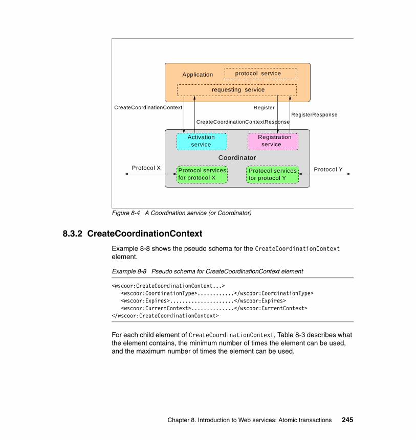
Figure 8-4 A Coordination service (or Coordinator)
8.3.2 CreateCoordinationContext
Example 8-8 shows the pseudo schema for the CreateCoordinationContext element.
Example 8-8 Pseudo schema for CreateCoordinationContext element
<wscoor:CreateCoordinationContext...><wscoor:CoordinationType>............</wscoor:CoordinationType><wscoor:Expires>.....................</wscoor:Expires><wscoor:CurrentContext>..............</wscoor:CurrentContext>
</wscoor:CreateCoordinationContext>
For each child element of CreateCoordinationContext, Table 8-3 describes what the element contains, the minimum number of times the element can be used, and the maximum number of times the element can be used.
Coordinator
Application
Registration service
Protocol services for protocol X
Protocol X
protocol service
CreateCoordinationContextResponseRegisterResponse
CreateCoordinationContext Register
Activation service
requesting service
Protocol services for protocol Y
Protocol Y
Chapter 8. Introduction to Web services: Atomic transactions 245
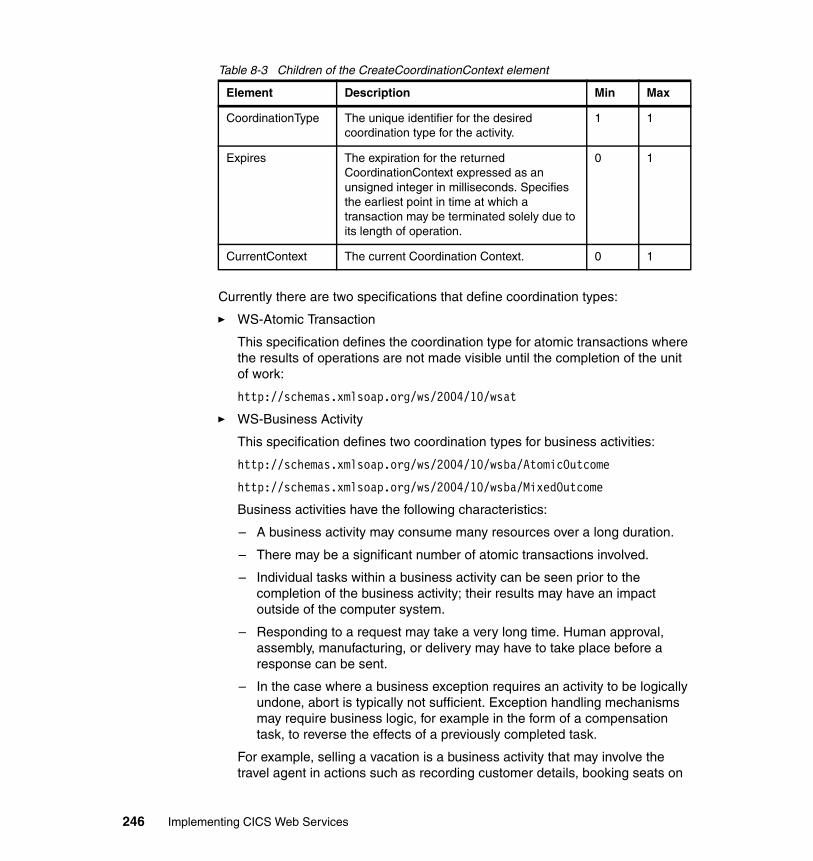
Table 8-3 Children of the CreateCoordinationContext element
Currently there are two specifications that define coordination types:
� WS-Atomic Transaction
This specification defines the coordination type for atomic transactions where the results of operations are not made visible until the completion of the unit of work:
http://schemas.xmlsoap.org/ws/2004/10/wsat
� WS-Business Activity
This specification defines two coordination types for business activities:
http://schemas.xmlsoap.org/ws/2004/10/wsba/AtomicOutcome
http://schemas.xmlsoap.org/ws/2004/10/wsba/MixedOutcome
Business activities have the following characteristics:
– A business activity may consume many resources over a long duration.
– There may be a significant number of atomic transactions involved.
– Individual tasks within a business activity can be seen prior to the completion of the business activity; their results may have an impact outside of the computer system.
– Responding to a request may take a very long time. Human approval, assembly, manufacturing, or delivery may have to take place before a response can be sent.
– In the case where a business exception requires an activity to be logically undone, abort is typically not sufficient. Exception handling mechanisms may require business logic, for example in the form of a compensation task, to reverse the effects of a previously completed task.
For example, selling a vacation is a business activity that may involve the travel agent in actions such as recording customer details, booking seats on
Element Description Min Max
CoordinationType The unique identifier for the desired coordination type for the activity.
1 1
Expires The expiration for the returned CoordinationContext expressed as an unsigned integer in milliseconds. Specifies the earliest point in time at which a transaction may be terminated solely due to its length of operation.
0 1
CurrentContext The current Coordination Context. 0 1
246 Implementing CICS Web Services
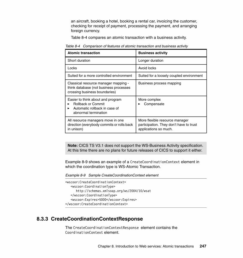
an aircraft, booking a hotel, booking a rental car, invoicing the customer, checking for receipt of payment, processing the payment, and arranging foreign currency.
Table 8-4 compares an atomic transaction with a business activity.
Table 8-4 Comparison of features of atomic transaction and business activity
Example 8-9 shows an example of a CreateCoordinationContext element in which the coordination type is WS-Atomic Transaction.
Example 8-9 Sample CreateCoordinationContext element
<wscoor:CreateCoordinationContext><wscoor:CoordinationType>
http://schemas.xmlsoap.org/ws/2004/10/wsat</wscoor:CoordinationType><wscoor:Expires>5000</wscoor:Expires>
</wscoor:CreateCoordinationContext>
8.3.3 CreateCoordinationContextResponse
The CreateCoordinationContextResponse element contains the CoordinationContext element.
Atomic transaction Business activity
Short duration Longer duration
Locks Avoid locks
Suited for a more controlled environment Suited for a loosely coupled environment
Classical resource manager mapping - think database (not business processes crossing business boundaries)
Business process mapping
Easier to think about and program� Rollback or Commit� Automatic rollback in case of
abnormal termination
More complex� Compensate
All resource managers move in one direction (everybody commits or rolls back in unison)
More flexible resource manager participation. They don’t have to trust applications so much.
Note: CICS TS V3.1 does not support the WS-Business Activity specification. At this time there are no plans for future releases of CICS to support it either.
Chapter 8. Introduction to Web services: Atomic transactions 247
The CoordinationContext element contains four elements:
� A URI which identifies the CoordinationContext.
� The CoordinationType.
� The expiration period for the CoordinationContext.
� An endpoint reference for the Registration Service which is part of this Coordination service. Recall from “Endpoint references” on page 237 that this means that the CoordinationContext must contain the address of the Registration Service and may contain reference properties for the Registration Service.
Example 8-10 shows the pseudo schema for the CreateCoordinationContextResponse element.
Example 8-10 Pseudo schema for CreateCoordinationContext Response element
<wscoor:CreateCoordinationContextResponse><wscoor:CoordinationContext>
<wscoor:Identifier>........................</wscoor:Identifier><wscoor:CoordinationType>..................</wscoor:CoordinationType><wscoor:Expires>...........................</wscoor:Expires><wscoor:RegistrationService>...............</wscoor:RegistrationService>
</wscoor:CoordinationContext></wscoor:CreateCoordinationContextResponse>
The application will place the CoordinationContext element within an application message to pass the coordination information to other parties. Conveying a CoordinationContext on an application message is commonly referred to as flowing the context. When a context is flowed as a SOAP header, the header must have the mustUnderstand attribute and the value of the mustUnderstand attribute must be true.
Example 8-11 shows a CoordinationContext created by a CICS TS V3.1 region.
Example 8-11 Sample CoordinationContext created by CICS
<wscoor:CoordinationContext><wscoor:Identifier>
PIAT-CCON-A6POT3C1-003322404576825C</wscoor:Identifier><wscoor:CoordinationType
http://schemas.xmlsoap.org/ws/2004/10/wsat</wscoor:CoordinationType>
Note: When an application flows the context, it passes the address of its Registration Service and the coordination type.
248 Implementing CICS Web Services
<wscoor:RegistrationService><wsa:Address>
http://MVSG3.mop.ibm.com:15301/cicswsat/RegistrationService</wsa:Address><wsa:ReferenceProperties>
<cicswsat:NetName>A6POT3C1</cicswsat:NetName><cicswsat:Token>F0F0F0F0</cicswsat:Token><cicswsat:UOWID>BCDB8F2E852B924C</cicswsat:UOWID>
</wsa:ReferenceProperties></wscoor:RegistrationService>
</wscoor:CoordinationContext>
Example 8-12 shows a CoordinationContext created by WebSphere Application Server V6.0.
Example 8-12 Sample CoordinationContext created by WebSphere
<wscoor:CoordinationContext><wscoor:Expires>Never</wscoor:Expires><wscoor:Identifier>
com.ibm.ws.wstx:00000107d70ad2...</wscoor:Identifier><wscoor:CoordinationType
http://schemas.xmlsoap.org/ws/2004/10/wsat</wscoor:CoordinationType><wscoor:RegistrationService>
<wsa:Address>http://9.100.199.156:9080/_IBMSYSAPP/wscoor/services/RegistrationCoordinatorPort
</wsa:Address><wsa:ReferenceProperties>
<websphere-wsat:txID xmlns:websphere-wsat=”......”>com.ibm.ws.wstx:00000107d70ad2...
</websphere-wsat:txID><websphere-wsat:instanceID xmlns:websphere-wsat=”......”
com.ibm.ws.wstx:00000107d70ad2...</websphere-wsat:instanceID>
</wsa:ReferenceProperties></wscoor:RegistrationService>
</wscoor:CoordinationContext>
Note: We noted from our tests that the content of the Expires element (that is, Never) is not an unsigned integer as required by the specification. This is planned to be changed in a future release of WebSphere Application Server.
Chapter 8. Introduction to Web services: Atomic transactions 249
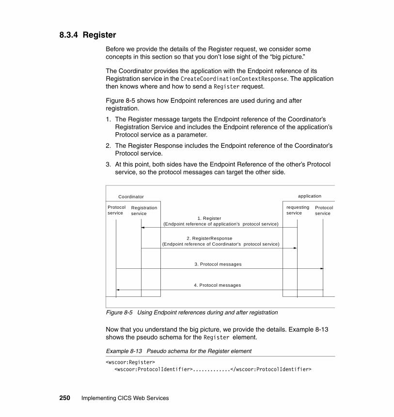
8.3.4 Register
Before we provide the details of the Register request, we consider some concepts in this section so that you don’t lose sight of the “big picture.”
The Coordinator provides the application with the Endpoint reference of its Registration service in the CreateCoordinationContextResponse. The application then knows where and how to send a Register request.
Figure 8-5 shows how Endpoint references are used during and after registration.
1. The Register message targets the Endpoint reference of the Coordinator’s Registration Service and includes the Endpoint reference of the application’s Protocol service as a parameter.
2. The Register Response includes the Endpoint reference of the Coordinator’s Protocol service.
3. At this point, both sides have the Endpoint Reference of the other’s Protocol service, so the protocol messages can target the other side.
Figure 8-5 Using Endpoint references during and after registration
Now that you understand the big picture, we provide the details. Example 8-13 shows the pseudo schema for the Register element.
Example 8-13 Pseudo schema for the Register element
<wscoor:Register><wscoor:ProtocolIdentifier>.............</wscoor:ProtocolIdentifier>
Protocolservice
4. Protocol messages
Registrationservice
Protocolservice
2. RegisterResponse(Endpoint reference of Coordinator's protocol service)
1. Register(Endpoint reference of application's protocol service)
requestingservice
applicationCoordinator
3. Protocol messages
250 Implementing CICS Web Services
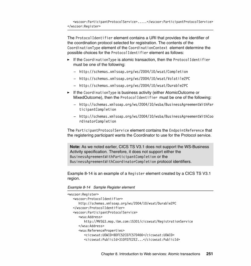
<wscoor:ParticipantProtocolService>.....</wscoor:ParticipantProtocolService></wscoor:Register>
The ProtocolIdentifier element contains a URI that provides the identifier of the coordination protocol selected for registration. The contents of the CoordinationType element of the CoordinationContext element determine the possible choices for the ProtocolIdentifier element as follows:
� If the CoordinationType is atomic transaction, then the ProtocolIdentifier must be one of the following:
– http://schemas.xmlsoap.org/ws/2004/10/wsat/Completion
– http://schemas.xmlsoap.org/ws/2004/10/wsat/Volatile2PC
– http://schemas.xmlsoap.org/ws/2004/10/wsat/Durable2PC
� If the CoordinationType is business activity (either AtomicOutcome or MixedOutcome), then the ProtocolIdentifier must be one of the following:
– http://schemas.xmlsoap.org/ws/2004/10/wsba/BusinessAgreementWithParticipantCompletion
– http://schemas.xmlsoap.org/ws/2004/10/wsba/BusinessAgreementWithCoordinatorCompletion
The ParticipantProtocolService element contains the EndpointReference that the registering participant wants the Coordinator to use for the Protocol service.
Example 8-14 is an example of a Register element created by a CICS TS V3.1 region.
Example 8-14 Sample Register element
<wscoor:Register><wscoor:ProtocolIdentifier>
http://schemas.xmlsoap.org/ws/2004/10/wsat/Durable2PC</wscoor:ProtocolIdentifier><wscoor:ParticipantProtocolService>
<wsa:Address> http://MVSG3.mop.ibm.com:15301/cicswsat/RegistrationService </wsa:Address> <wsa:ReferenceProperties> <cicswsat:UOWID>BDFC52CD7C57D466</cicswsat:UOWID> <cicswsat:PublicId>310FD7E2E2...</cicswsat:PublicId>
Note: As we noted earlier, CICS TS V3.1 does not support the WS-Business Activity specification. Therefore, it does not support either the BusinessAgreementWithParticipantCompletion or the BusinessAgreementWithCoordinatorCompletion protocol identifiers.
Chapter 8. Introduction to Web services: Atomic transactions 251
</wsa:ReferenceProperties> </wscoor:ParticipantProtocolService>
</wscoor:Register>
8.3.5 RegisterResponse
Example 8-15 shows the pseudo schema for the RegisterResponse element.
Example 8-15 Pseudo schema for the RegisterResponse element
<wscoor:RegisterResponse><wscoor:CoordinatorProtocolService>.....</wscoor:CoordinatorProtocolService>
</wscoor:RegisterResponse>
The CoordinatorProtocolService element contains the EndpointReference that the Coordination service wants the registered participant to use for the Protocol service.
We note, once again, that when the application has received the RegisterResponse, each side has the EndpointReference of the other’s Protocol Service.
8.3.6 Two applications with their own coordinators
In this section we see how two application services (App1 and App2) with their own coordinators (Coordinator A and Coordinator B) interact as an activity propagates between them. Coordinator A provides Activation service ASa, Registration service RSa, and Protocol service Pa. Coordinator B provides Activation service ASb, Registration service RSb, and Protocol service Pb. Figure 8-6 shows the two applications with their own coordinators.
Note: CICS TS V3.1 uses a single endpoint address for its Registration service, Protocol service, and fault messages. Other products, such as WebSphere Application Server V6.0 use separate addresses for each of these.
252 Implementing CICS Web Services
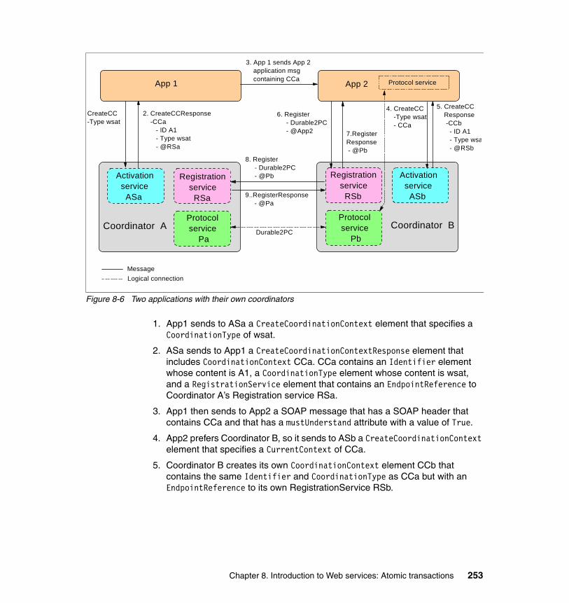
Figure 8-6 Two applications with their own coordinators
1. App1 sends to ASa a CreateCoordinationContext element that specifies a CoordinationType of wsat.
2. ASa sends to App1 a CreateCoordinationContextResponse element that includes CoordinationContext CCa. CCa contains an Identifier element whose content is A1, a CoordinationType element whose content is wsat, and a RegistrationService element that contains an EndpointReference to Coordinator A’s Registration service RSa.
3. App1 then sends to App2 a SOAP message that has a SOAP header that contains CCa and that has a mustUnderstand attribute with a value of True.
4. App2 prefers Coordinator B, so it sends to ASb a CreateCoordinationContext element that specifies a CurrentContext of CCa.
5. Coordinator B creates its own CoordinationContext element CCb that contains the same Identifier and CoordinationType as CCa but with an EndpointReference to its own RegistrationService RSb.
Registration service RSb
Protocol service Pb
Activation service ASb
Coordinator A
Registration service RSa
Protocol service Pa
Activation service ASa
Coordinator B
7.RegisterResponse - @Pb
5. CreateCC Response -CCb - ID A1 - Type wsa - @RSb
4. CreateCC -Type wsat - CCa
2. CreateCCResponse -CCa - ID A1 - Type wsat - @RSa
CreateCC -Type wsat
6. Register - Durable2PC - @App2
3. App 1 sends App 2 application msg containing CCa App 2 Protocol serviceApp 1
Logical connectionMessage
9..RegisterResponse - @Pa
8. Register - Durable2PC - @Pb
Durable2PC
Chapter 8. Introduction to Web services: Atomic transactions 253
The WS-Atomic Transaction specification which we discuss in detail in “WS-Atomic Transaction” on page 254 states that:
– If the CreateCoordinationContext request includes the CurrentContext element, then the target coordinator is interposed as a subordinate to the coordinator stipulated inside the CurrentContext element.
– If the CreateCoordinationContext request does not include a CurrentContext element, then the target coordinator creates a new transaction and acts as the root coordinator.
6. App2 determines the coordination protocols supported by the wsat coordination type and then sends a Register element to RSb. This Register element contains a ProtocolIdentifier of Durable2PC and an EndpointReference to App2’s Protocol service.
7. RSb sends back to App2 a RegisterResponse element that contains an EndpointReference to Protocol service Pb. This forms a logical connection (which the Durable2PC protocol can use) between the Endpoint reference for App2’s Protocol service and the Endpoint reference for Coordinator B’s Protocol service Pb.
8. This registration causes Coordinator B to forward the registration on to Coordinator A’s Registration service RSa.
9. RSa sends back to Coordinator B a RegisterResponse element that contains an EndpointReference to Protocol Service Pa. This forms a logical connection between the EndpointReferences for Pa and Pb that the Durable2PC protocol can use.
8.3.7 Addressing requirements for WS-Coordination message types
CreateCoordinationContext and Register messages:
� Must include a wsa:MessageID header
� Must include a wsa:ReplyTo header
CreateCoordinationContextResponse and RegisterResponse messages:
� Must include a wsa:RelatesTo header that specifies the MessageID from the corresponding request message
8.4 WS-Atomic Transaction
As we discussed in “WS-Coordination” on page 243, the WS-Coordination specification defines an extensible framework for defining coordination types.
254 Implementing CICS Web Services
The WS-Atomic Transaction specification builds on WS-Coordination by providing the definition of the atomic transaction coordination type.
Atomic transactions have an all-or-nothing property. The actions taken prior to commit are only tentative (that is, not persistent and not visible to other activities). When an application finishes, it requests the Coordinator to determine the outcome for the transaction. The Coordinator determines if there were any processing failures by asking the participants to vote. If the participants all vote that they were able to execute successfully, the Coordinator commits all actions taken. If a participant votes that it needs to abort or a participant does not respond at all, the Coordinator aborts all actions taken. Commit makes the tentative actions visible to other transactions. Abort makes the tentative actions appear as if the actions never happened.
IBM, Microsoft, and BEA published the Web Services- Atomic Transaction (WS - Atomic Transaction) specification in September, 2003; they updated it in November, 2004. Arjuna Technologies Ltd., Hitachi Ltd., and IONA Technologies joined IBM, Microsoft, and BEA in publishing Web Services - Atomic Transaction (WS - Atomic Transaction) Version 1.0 in August, 2005. You can find these at:
http://www-128.ibm.com/developerworks/library/specification/ws-tx
Although CICS TS V3.1 was developed and tested when the November, 2004, version was the current version, the nature of the differences between the November, 2004 version and the August, 2005 version is such that it may accurately be said that CICS TS V3.1 also supports the August, 2005 version.
All information items defined by the November, 2004 and August, 2005 versions are identified by the XML namespace URI:
http://schemas.xmlsoap.org/ws/2004/10/wsat
We associate the namespace prefix wsat with this namespace by using the attribute:
xmlns:wsat="http://schemas.xmlsoap.org/ws/2004/10/wsat"
The WS-AT specification defines the following protocols for atomic transactions:
� Completion
� Volatile Two-Phase Commit
� Durable Two-Phase Commit
Chapter 8. Introduction to Web services: Atomic transactions 255
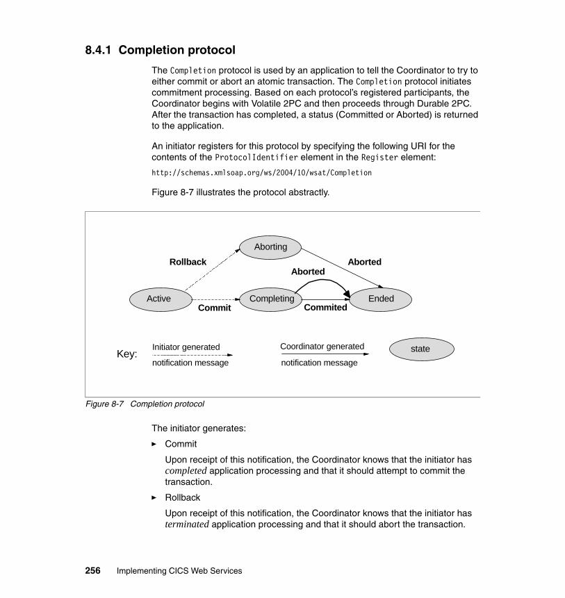
8.4.1 Completion protocol
The Completion protocol is used by an application to tell the Coordinator to try to either commit or abort an atomic transaction. The Completion protocol initiates commitment processing. Based on each protocol’s registered participants, the Coordinator begins with Volatile 2PC and then proceeds through Durable 2PC. After the transaction has completed, a status (Committed or Aborted) is returned to the application.
An initiator registers for this protocol by specifying the following URI for the contents of the ProtocolIdentifier element in the Register element:
http://schemas.xmlsoap.org/ws/2004/10/wsat/Completion
Figure 8-7 illustrates the protocol abstractly.
Figure 8-7 Completion protocol
The initiator generates:
� Commit
Upon receipt of this notification, the Coordinator knows that the initiator has completed application processing and that it should attempt to commit the transaction.
� Rollback
Upon receipt of this notification, the Coordinator knows that the initiator has terminated application processing and that it should abort the transaction.
EndedCommited
Aborting
CompletingActive
Aborted
Commit
Rollback Aborted
Coordinator generated
notification message
Initiator generated
notification messagestateKey:
256 Implementing CICS Web Services
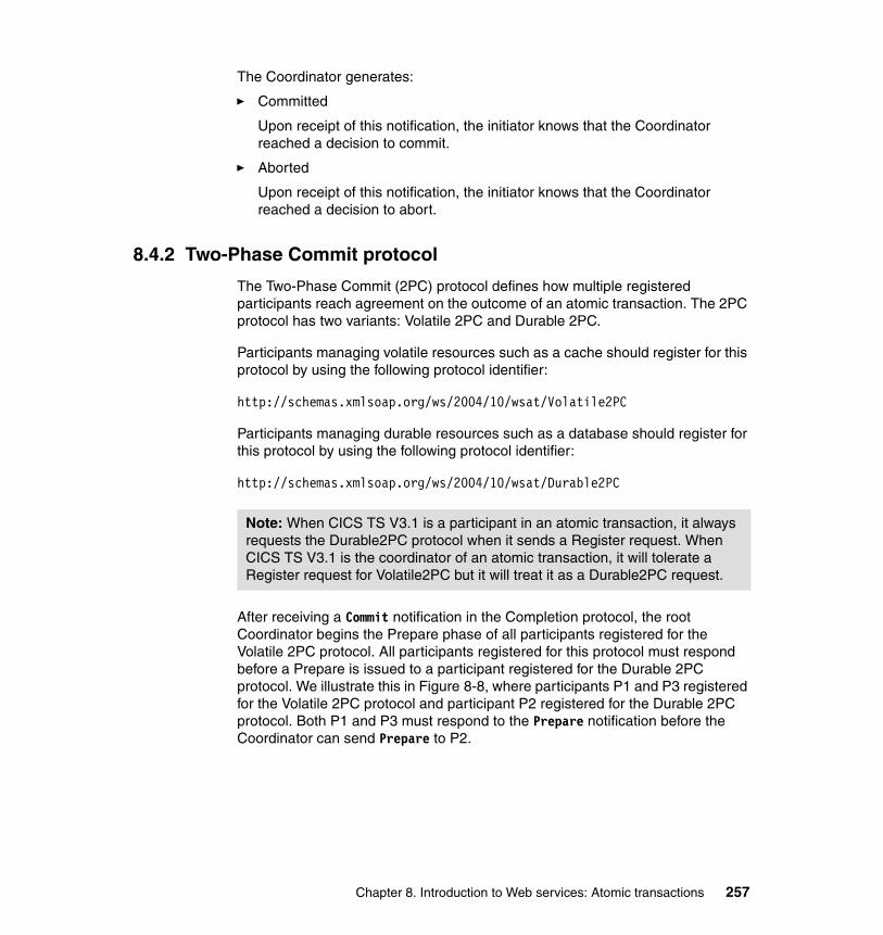
The Coordinator generates:
� Committed
Upon receipt of this notification, the initiator knows that the Coordinator reached a decision to commit.
� Aborted
Upon receipt of this notification, the initiator knows that the Coordinator reached a decision to abort.
8.4.2 Two-Phase Commit protocol
The Two-Phase Commit (2PC) protocol defines how multiple registered participants reach agreement on the outcome of an atomic transaction. The 2PC protocol has two variants: Volatile 2PC and Durable 2PC.
Participants managing volatile resources such as a cache should register for this protocol by using the following protocol identifier:
http://schemas.xmlsoap.org/ws/2004/10/wsat/Volatile2PC
Participants managing durable resources such as a database should register for this protocol by using the following protocol identifier:
http://schemas.xmlsoap.org/ws/2004/10/wsat/Durable2PC
After receiving a Commit notification in the Completion protocol, the root Coordinator begins the Prepare phase of all participants registered for the Volatile 2PC protocol. All participants registered for this protocol must respond before a Prepare is issued to a participant registered for the Durable 2PC protocol. We illustrate this in Figure 8-8, where participants P1 and P3 registered for the Volatile 2PC protocol and participant P2 registered for the Durable 2PC protocol. Both P1 and P3 must respond to the Prepare notification before the Coordinator can send Prepare to P2.
Note: When CICS TS V3.1 is a participant in an atomic transaction, it always requests the Durable2PC protocol when it sends a Register request. When CICS TS V3.1 is the coordinator of an atomic transaction, it will tolerate a Register request for Volatile2PC but it will treat it as a Durable2PC request.
Chapter 8. Introduction to Web services: Atomic transactions 257
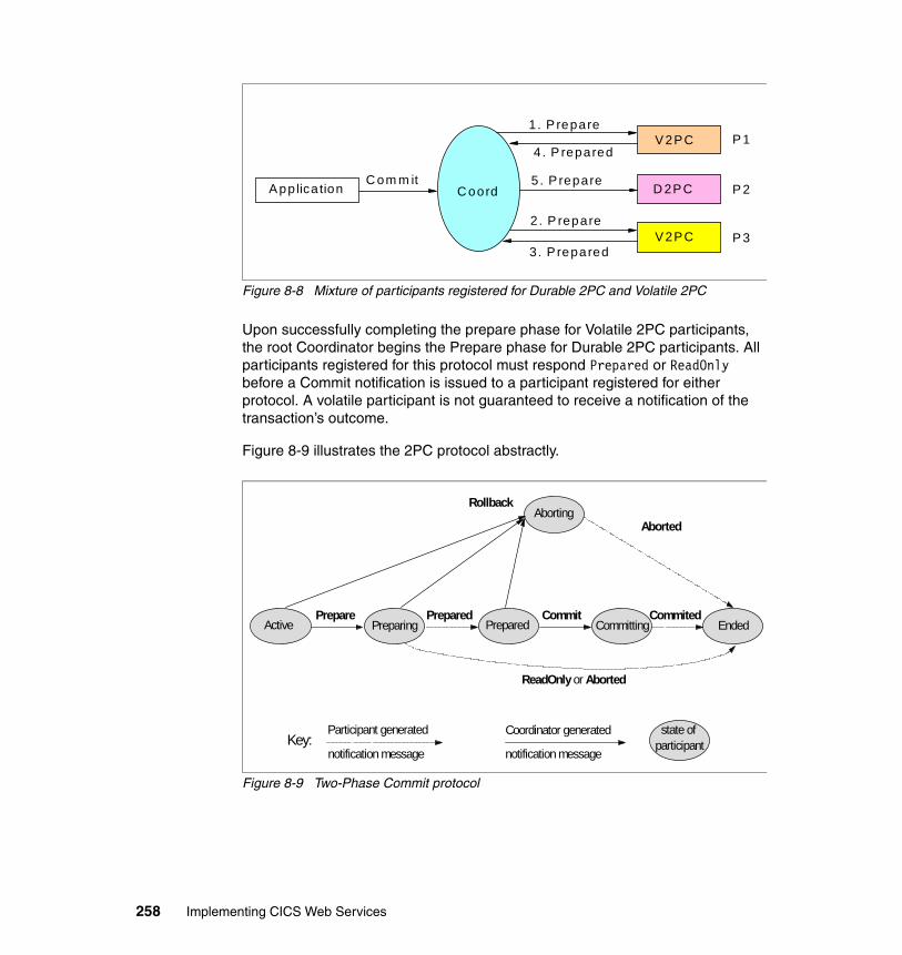
Figure 8-8 Mixture of participants registered for Durable 2PC and Volatile 2PC
Upon successfully completing the prepare phase for Volatile 2PC participants, the root Coordinator begins the Prepare phase for Durable 2PC participants. All participants registered for this protocol must respond Prepared or ReadOnly before a Commit notification is issued to a participant registered for either protocol. A volatile participant is not guaranteed to receive a notification of the transaction’s outcome.
Figure 8-9 illustrates the 2PC protocol abstractly.
Figure 8-9 Two-Phase Commit protocol
V2PC
D 2PC
V2PC
P 3
P 2
P 1
Applica tion C oordC om m it 5 . P repare
1. P repare
4 . P repared
2 . P repare
3. P repared
Coordinator generated
notification message
Participant generated
notification message
state ofparticipant Key:
Aborting
Active Prepared EndedPreparing Committing
ReadOnly or Aborted
Prepare
Rollback
Aborted
Prepared Commit Commited
258 Implementing CICS Web Services
The Coordinator generates:
� Prepare
Upon receipt of this notification, the participant should enter phase 1 and vote on the outcome of the transaction.
– If the participant has already voted, it should resend the same vote.
– If the participant does not know of the transaction, it must vote to abort.
� Rollback
Upon receipt of this notification, the participant should abort, and forget, the transaction. This notification can be sent in either phase 1 or phase 2. Once sent, the Coordinator may forget all knowledge of this transaction.
� Commit
Upon receipt of this notification, the participant should commit the transaction.This notification can only be sent after phase 1, and if the participant voted to commit. If the participant does not know of the transaction, it must send a Committed notification to the Coordinator.
The participant generates:
� Prepared
The participant is prepared and votes to commit the transaction.
� ReadOnly
The participant votes to commit the transaction and has forgotten the transaction. The participant does not wish to participate in phase two.
Suppose, for example, that the participant received an account number that it could not match to an entry in a database. It might return an error to the requesting application, but, having registered as a participant in the atomic transaction, it would then go on to be coordinated during 2PC processing. When the Coordinator sends Prepare, the participant replies ReadOnly and then terminates without waiting for the Commit. The Coordinator, on receipt of the ReadOnly, would then delete its own record of the interaction with the participant and would not attempt to send a Commit to it.
� Aborted
The participant has aborted, and forgotten, the transaction.
� Committed
The participant has committed the transaction. The Coordinator may safely forget that participant.
Chapter 8. Introduction to Web services: Atomic transactions 259
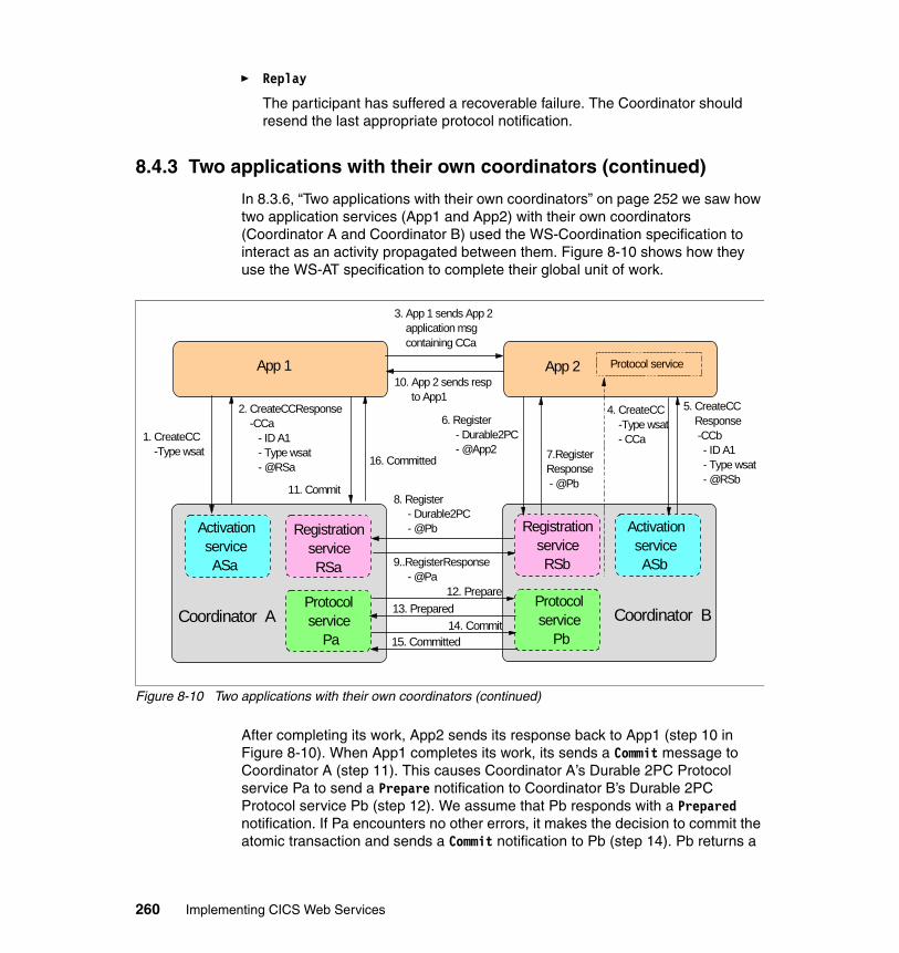
� Replay
The participant has suffered a recoverable failure. The Coordinator should resend the last appropriate protocol notification.
8.4.3 Two applications with their own coordinators (continued)
In 8.3.6, “Two applications with their own coordinators” on page 252 we saw how two application services (App1 and App2) with their own coordinators (Coordinator A and Coordinator B) used the WS-Coordination specification to interact as an activity propagated between them. Figure 8-10 shows how they use the WS-AT specification to complete their global unit of work.
Figure 8-10 Two applications with their own coordinators (continued)
After completing its work, App2 sends its response back to App1 (step 10 in Figure 8-10). When App1 completes its work, its sends a Commit message to Coordinator A (step 11). This causes Coordinator A’s Durable 2PC Protocol service Pa to send a Prepare notification to Coordinator B’s Durable 2PC Protocol service Pb (step 12). We assume that Pb responds with a Prepared notification. If Pa encounters no other errors, it makes the decision to commit the atomic transaction and sends a Commit notification to Pb (step 14). Pb returns a
Registration service RSb
Protocol service Pb
Activation service ASb
Coordinator B
2. CreateCCResponse -CCa - ID A1 - Type wsat - @RSa 16. Committed
Coordinator A
Registration service RSa
Protocol service Pa
Activation service ASa
App 2 Protocol serviceApp 1
1. CreateCC -Type wsat
11. Commit
6. Register - Durable2PC - @App2
10. App 2 sends resp to App1
3. App 1 sends App 2 application msg containing CCa
7.RegisterResponse - @Pb
5. CreateCC Response -CCb - ID A1 - Type wsat - @RSb
4. CreateCC -Type wsat - CCa
9..RegisterResponse - @Pa
8. Register - Durable2PC - @Pb
15. Committed14. Commit
12. Prepare13. Prepared
260 Implementing CICS Web Services
Committed notification and then completes its updates before terminating. When Coordinator A receives this notification, it commits its own updates and notifies App1 of the outcome (step 16).
8.4.4 Addressing requirements for WS-AT message types
The messages defined in the WS-AT specification are notification messages; that is, they are one-way messages. There are two types of notification messages:
� A notification message is a terminal message when it indicates the end of a coordinator/participant relationship. Committed, Aborted, and ReadOnly are terminal messages.
� A notification message is a non-terminal message when it does not indicate the end of a coordinator/participant relationship. Commit, Rollback, Prepare, Prepared, and Replay are non-terminal messages.
Non-terminal notification messages must include a wsa:ReplyTo header.
8.4.5 CICS TS V3.1 and resynchronization processing
We have completed our discussion of the WS-AT specification. Unfortunately, the current version of the specification does not completely cover all of the issues surrounding the use of the 2PC protocol. In particular, it does not completely describe the resynchronization processing that should take place following a failure in one of the systems involved in the 2PC protocol or in the network connections that link the systems together. The only thing that the specification mentions relating to resynchronization is the Replay notification. Therefore, in this section we describe some aspects of how CICS TS V3.1 handles resynchronization processing for transactions that use the 2PC protocol.
Network failures can result in messages not being delivered in a timely manner. System failures prevent processing altogether until a restart takes place.
Within the 2PC processing sequence there is a period of time, known as the in-doubt window, during which one system is unable to complete processing
Note: For the sake of brevity we do not describe all of the possible issues. For example, we do not describe:
� What happens when resync processing is driven from both sides and a race condition results
� What happens when a resync request fails
Chapter 8. Introduction to Web services: Atomic transactions 261
because it does not know what the other system has done. The distributed UOW is said to be in-doubt when:
� A participant Protocol service has replied Prepared in response to a Prepare notification, and
� Has written a log record of its response to signify that it has entered the in-doubt state, and
� Does not yet know the decision of its coordinator (to Commit or to Rollback).
Barring system or network failures, the UOW remains in-doubt until the coordinator issues either the Commit or Rollback request as a result of responses received from all UOW participants. If a failure occurs that causes loss of connectivity between a participant and its coordinator, the UOW remains in-doubt until either:
� Recovery from the failure has taken place and synchronization can resume, or
� The in-doubt waiting period is terminated by some built-in control mechanism, and an arbitrary (heuristic) decision is then taken (to commit or back out).
Note that while the UOW remains in-doubt, the recoverable resources that it owns remain locked.
If a system or network failure occurs during the in-doubt window, additional steps must be taken to ensure that the updates are completed in a consistent manner by both systems. This is known as resynchronization processing.
Previous releases of CICS provided a Recovery Manager that dealt with resynchronization processing for distributed workloads that made use of VTAM networks or that used MRO connections. These releases dealt with failures during the in-doubt window in one of three ways:
� Automatic heuristic decision
You could cause CICS to make an automatic heuristic decision by specifying the WAIT, WAITTIME, and ACTION attributes on a TRANSACTION definition as follows:
– If you set the WAIT attribute to NO, then CICS took whatever action was specified on the ACTION attribute (either COMMIT or BACKOUT) immediately.
– If you set the WAIT attribute to YES and the WAITTIME attribute to a non-zero value, then CICS took whatever action was specified on the ACTION attribute after waiting for the amount of time specified in WAITTIME (assuming normal recovery and resynchronization had not already taken place).
262 Implementing CICS Web Services
� Manual heuristic decision
You could force an in-doubt UOW to complete by issuing a CEMT SET UOW(uowid) [COMMIT | BACKOUT] command or its EXEC CICS equivalent.
� Automatic resynchronization
If you set the WAIT attribute to YES and the WAITTIME attribute to 00.00.00, the transaction would wait until it could communicate with its partner system, after which it could either explicitly request that the message it was waiting for be sent again, or it could resend the last message that it generated.
CICS TS V3.1 extends the Recovery Manager for use by WS-AT workloads. CICS applications that form part of a WS-AT workload can be controlled by any of these mechanisms. However, automatic resynchronization is somewhat different for WS-AT workloads.
The principle difference arises from the fact that WS-AT processing takes place over a TCP/IP network.
� Other forms of distributed transactions make use of communication mechanisms such as VTAM, and resynchronization across a VTAM network can be triggered when the connection between a pair of systems is re-established.
� CICS does not currently support TCP/IP connections in the same way that it does its VTAM connections, and so CICS can only drive resynchronization of WS-AT requests when a region starts.
During any type of startup except an initial start, CICS reads the system log to discover any units of work that were in-doubt when the region previously shut down or failed. While reading through the log, CICS may find that it has outstanding units of work that indicate they were involved in an atomic transaction. These log records also indicate whether the UOW was acting as a coordinator or a participant.
� Coordinator
If it is a coordinator and the log record indicates that the UOW was waiting for a Committed or Aborted response from a participant when CICS shut down, then the UOW is reactivated (unshunted) and sends out its decision message (Commit or Rollback) to the participant identified in the log record.
– If a response is received, then the UOW completes its processing and terminates.
Important: CICS only drives resynchronization of WS-AT requests during a CICS region restart.
Chapter 8. Introduction to Web services: Atomic transactions 263
– If a response is not received before the coordination UOW times out, then CICS shunts the UOW (moves it aside for processing later on). The UOW then persists until another resynchronization attempt takes place or until someone manually forces it to complete. (The coordination UOW times out after 30 seconds, a value set internally by CICS).
� Participant
If it is a participant and the log record indicates that the UOW had voted in response to a Prepare message and was waiting for a Commit or Rollback decision from its coordinator when communication was lost, then the UOW is reactivated, sends a Replay message to its coordinator, and once again waits for the decision message to arrive.
– If the decision message is then received, the participant acts on it and sends a Committed or Aborted message back to the coordinator before terminating.
– If the decision message does not arrive before the participant UOW times out, then CICS shunts the participant UOW. The UOW then persists until another resynchronization attempt takes place or until someone manually forces it to complete.
264 Implementing CICS Web Services
Chapter 9. Enabling atomic transactions
We begin this chapter by showing you how to enable atomic transactions in CICS. We start with the simple case where we have a service requester application running in CICS AOR1 invoking a service provider application running in CICS AOR2. Then we move to the more elaborate case where two CICSplexes are working together, one acting as service requester and the other as service provider. We conclude the chapter by showing you how to enable atomic transactions in WebSphere Application Server.
9
© Copyright IBM Corp. 2006. All rights reserved. 265
9.1 Enabling atomic transactions in CICS
We recognize that it is not likely that many customers will choose to use WS-AT for workloads distributed entirely within CICS. More typically, CICS would participate in an atomic transaction as a Web service provider with the service requester running under the control of another product such as WebSphere Application Server V6 or later. Customers might also use a CICS transaction acting as a Web service requester to participate in an atomic transaction with a service provider running under the control of another product.
Nevertheless, we start with the special case of one CICS region acting as a service requester participating in an atomic transaction with another CICS region acting as a service provider. This will illustrate the capacity of CICS to undertake both the role of a coordinator of an atomic transaction and the role of a participant in an atomic transaction.
9.1.1 CICS to CICS configuration
Figure 9-1 shows two CICS regions: AOR1 and AOR2. A service requester application running in AOR1 invokes a service provider application running in AOR2.
In AOR1 the request passes through a pipeline that contains a CICS-provided message handler module (either DFHPISN1, if SOAP 1.1 is being used; or DFHPISN2, if SOAP 1.2 is being used). DFHPISNx invokes the CICS-provided header processing program DFHWSATH. DFHWSATH adds a SOAP header containing a CoordinationContext to each message that it sends out.
In AOR2 the request passes through a pipeline that supports the Web service that AOR1’s application is calling and also invokes DFHPISNx. DFHPISNx invokes the header processing program DFHWSATH when it detects a SOAP header that contains a CoordinationContext.
266 Implementing CICS Web Services
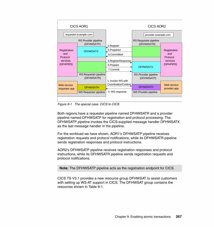
Figure 9-1 The special case: CICS to CICS
Both regions have a requester pipeline named DFHWSATR and a provider pipeline named DFHWSATP for registration and protocol processing. The DFHWSATP pipeline invokes the CICS-supplied message handler DFHWSATX as the last message handler in the pipeline.
For the workload we have shown, AOR1’s DFHWSATP pipeline receives registration requests and protocol notifications, while its DFHWSATR pipeline sends registration responses and protocol instructions.
AOR2’s DFHWSATP pipeline receives registration responses and protocol instructions, while its DFHWSATR pipeline sends registration requests and protocol notifications.
CICS TS V3.1 provides a new resource group DFHWSAT to assist customers with setting up WS-AT support in CICS. The DFHWSAT group contains the resources shown in Table 9-1.
Note: The DFHWSATP pipeline acts as the registration endpoint for CICS.
requester.example.com
CICS AOR1 CICS AOR2
provider.example.com
WS Requester pipeline
Web servicerequester app DFHWSATH
Web serviceprovider app
WS Provider pipeline
DFHWSATH
RS Provider pipeline (DFHWSATP)
RS Requester pipeline (DFHWSATR)
DFHWSATX
Registration and Protocol services(DFHPIRS)
RS Requester pipeline (DFHWSATR)
RS Provider pipeline (DFHWSATP)
DFHWSATX
1. Invoke WS withCoordinationContext
4. WS response
8.Committed
2.Register6.Prepared
7.Commit
3.RegisterResponse5.Prepare
Registration and Protocol services(DFHPIRS)
Chapter 9. Enabling atomic transactions 267
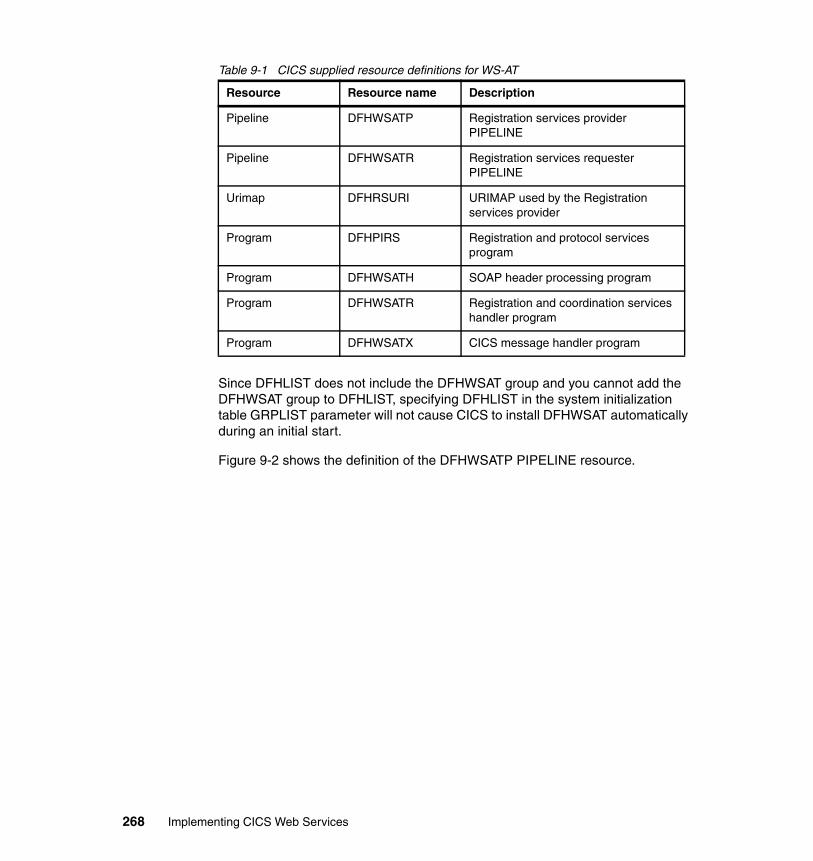
Table 9-1 CICS supplied resource definitions for WS-AT
Since DFHLIST does not include the DFHWSAT group and you cannot add the DFHWSAT group to DFHLIST, specifying DFHLIST in the system initialization table GRPLIST parameter will not cause CICS to install DFHWSAT automatically during an initial start.
Figure 9-2 shows the definition of the DFHWSATP PIPELINE resource.
Resource Resource name Description
Pipeline DFHWSATP Registration services provider PIPELINE
Pipeline DFHWSATR Registration services requester PIPELINE
Urimap DFHRSURI URIMAP used by the Registration services provider
Program DFHPIRS Registration and protocol services program
Program DFHWSATH SOAP header processing program
Program DFHWSATR Registration and coordination services handler program
Program DFHWSATX CICS message handler program
268 Implementing CICS Web Services
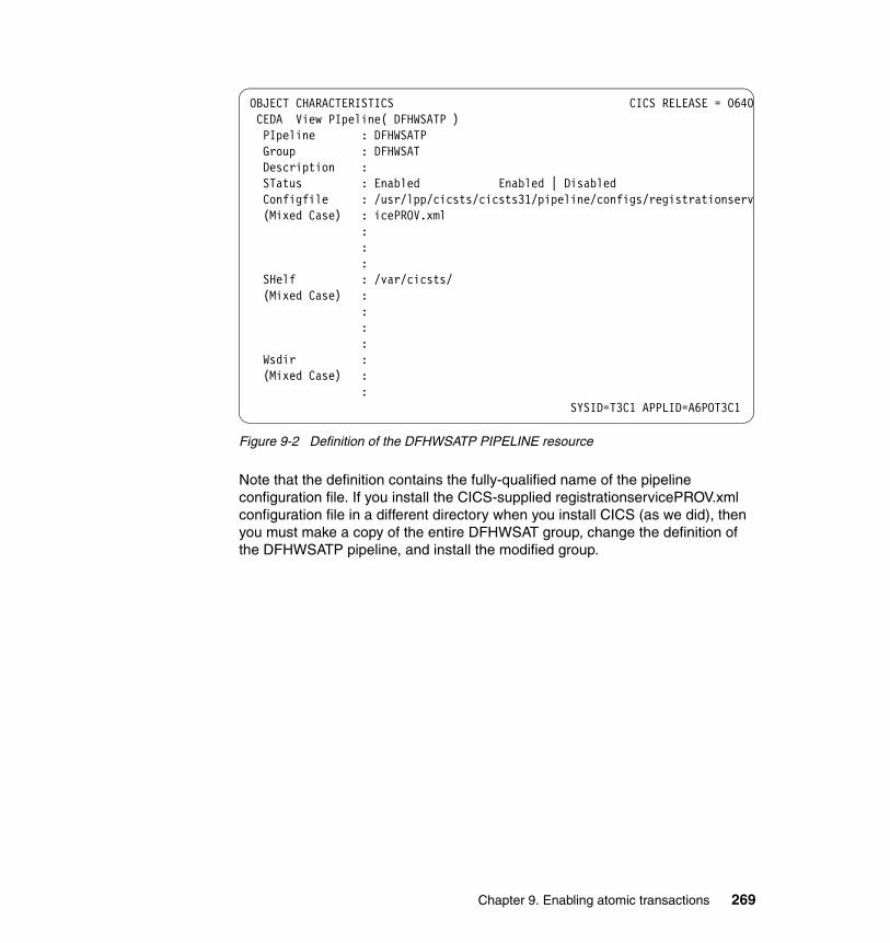
Figure 9-2 Definition of the DFHWSATP PIPELINE resource
Note that the definition contains the fully-qualified name of the pipeline configuration file. If you install the CICS-supplied registrationservicePROV.xml configuration file in a different directory when you install CICS (as we did), then you must make a copy of the entire DFHWSAT group, change the definition of the DFHWSATP pipeline, and install the modified group.
OBJECT CHARACTERISTICS CICS RELEASE = 0640 CEDA View PIpeline( DFHWSATP ) PIpeline : DFHWSATP Group : DFHWSAT Description : STatus : Enabled Enabled | Disabled Configfile : /usr/lpp/cicsts/cicsts31/pipeline/configs/registrationserv (Mixed Case) : icePROV.xml : : : SHelf : /var/cicsts/ (Mixed Case) : : : : Wsdir : (Mixed Case) : :
SYSID=T3C1 APPLID=A6POT3C1
Chapter 9. Enabling atomic transactions 269
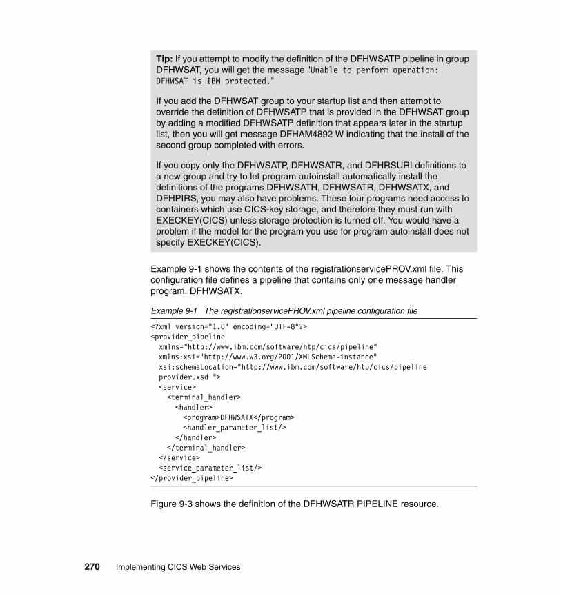
Example 9-1 shows the contents of the registrationservicePROV.xml file. This configuration file defines a pipeline that contains only one message handler program, DFHWSATX.
Example 9-1 The registrationservicePROV.xml pipeline configuration file
<?xml version="1.0" encoding="UTF-8"?> <provider_pipeline xmlns="http://www.ibm.com/software/htp/cics/pipeline"
xmlns:xsi="http://www.w3.org/2001/XMLSchema-instance" xsi:schemaLocation="http://www.ibm.com/software/htp/cics/pipeline provider.xsd ">
<service> <terminal_handler> <handler> <program>DFHWSATX</program> <handler_parameter_list/> </handler> </terminal_handler> </service> <service_parameter_list/> </provider_pipeline>
Figure 9-3 shows the definition of the DFHWSATR PIPELINE resource.
Tip: If you attempt to modify the definition of the DFHWSATP pipeline in group DFHWSAT, you will get the message "Unable to perform operation: DFHWSAT is IBM protected."
If you add the DFHWSAT group to your startup list and then attempt to override the definition of DFHWSATP that is provided in the DFHWSAT group by adding a modified DFHWSATP definition that appears later in the startup list, then you will get message DFHAM4892 W indicating that the install of the second group completed with errors.
If you copy only the DFHWSATP, DFHWSATR, and DFHRSURI definitions to a new group and try to let program autoinstall automatically install the definitions of the programs DFHWSATH, DFHWSATR, DFHWSATX, and DFHPIRS, you may also have problems. These four programs need access to containers which use CICS-key storage, and therefore they must run with EXECKEY(CICS) unless storage protection is turned off. You would have a problem if the model for the program you use for program autoinstall does not specify EXECKEY(CICS).
270 Implementing CICS Web Services
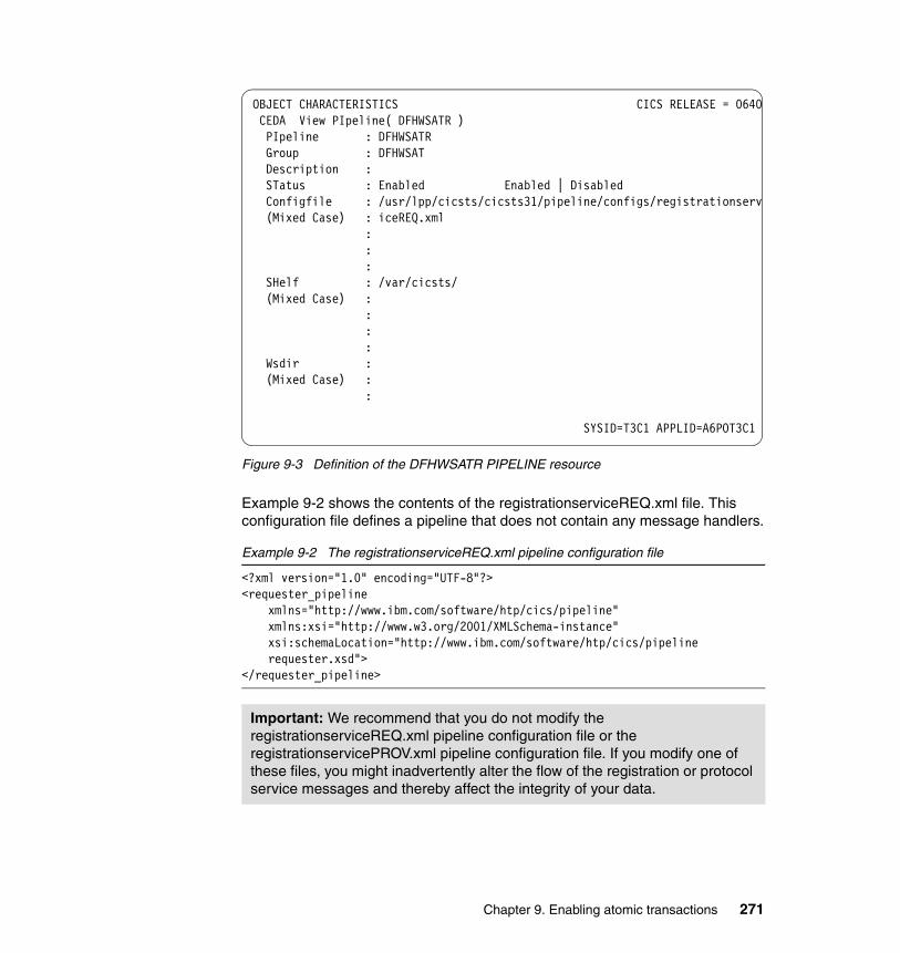
Figure 9-3 Definition of the DFHWSATR PIPELINE resource
Example 9-2 shows the contents of the registrationserviceREQ.xml file. This configuration file defines a pipeline that does not contain any message handlers.
Example 9-2 The registrationserviceREQ.xml pipeline configuration file
<?xml version="1.0" encoding="UTF-8"?> <requester_pipeline
xmlns="http://www.ibm.com/software/htp/cics/pipeline" xmlns:xsi="http://www.w3.org/2001/XMLSchema-instance" xsi:schemaLocation="http://www.ibm.com/software/htp/cics/pipeline requester.xsd">
</requester_pipeline>
Important: We recommend that you do not modify the registrationserviceREQ.xml pipeline configuration file or the registrationservicePROV.xml pipeline configuration file. If you modify one of these files, you might inadvertently alter the flow of the registration or protocol service messages and thereby affect the integrity of your data.
OBJECT CHARACTERISTICS CICS RELEASE = 0640 CEDA View PIpeline( DFHWSATR ) PIpeline : DFHWSATR Group : DFHWSAT Description : STatus : Enabled Enabled | Disabled Configfile : /usr/lpp/cicsts/cicsts31/pipeline/configs/registrationserv (Mixed Case) : iceREQ.xml : : : SHelf : /var/cicsts/ (Mixed Case) : : : : Wsdir : (Mixed Case) : :
SYSID=T3C1 APPLID=A6POT3C1
Chapter 9. Enabling atomic transactions 271
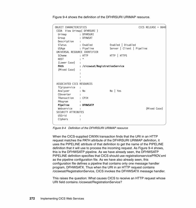
Figure 9-4 shows the definition of the DFHRSURI URIMAP resource.
Figure 9-4 Definition of the DFHRSURI URIMAP resource
When the CICS-supplied CWXN transaction finds that the URI in an HTTP request matches the PATH attribute of the DFHRSURI URIMAP definition, it uses the PIPELINE attribute of that definition to get the name of the PIPELINE definition that it will use to process the incoming request. As Figure 9-4 shows, this is the DFHWSATP pipeline. As we have already seen, the DFHWSATP PIPELINE definition specifies that CICS should use registrationservicePROV.xml as the pipeline configuration file. As we have also already seen, this configuration file defines a pipeline that contains only one message handler program, DFHWSATX. Thus when the URI in an HTTP request contains /cicswsat/RegistrationService, CICS invokes the DFHWSATX message handler.
This raises the question: What causes CICS to receive an HTTP request whose URI field contains /cicswsat/RegistrationService?
OBJECT CHARACTERISTICS CICS RELEASE = 0640 CEDA View Urimap( DFHRSURI ) Urimap : DFHRSURI Group : DFHWSAT Description : STatus : Enabled Enabled | Disabled USAge : Pipeline Server | Client | Pipeline UNIVERSAL RESOURCE IDENTIFIER SCheme : HTTP HTTP | HTTPS HOST : * (Lower Case) : PAth : /cicswsat/RegistrationService (Mixed Case) : : : : ASSOCIATED CICS RESOURCES TCpipservice : Analyzer : No No | Yes COnverter :
TRansaction : CPIH PRogram : PIpeline : DFHWSATP Webservice : (Mixed Case) SECURITY ATTRIBUTES USErid : CIphers :
272 Implementing CICS Web Services
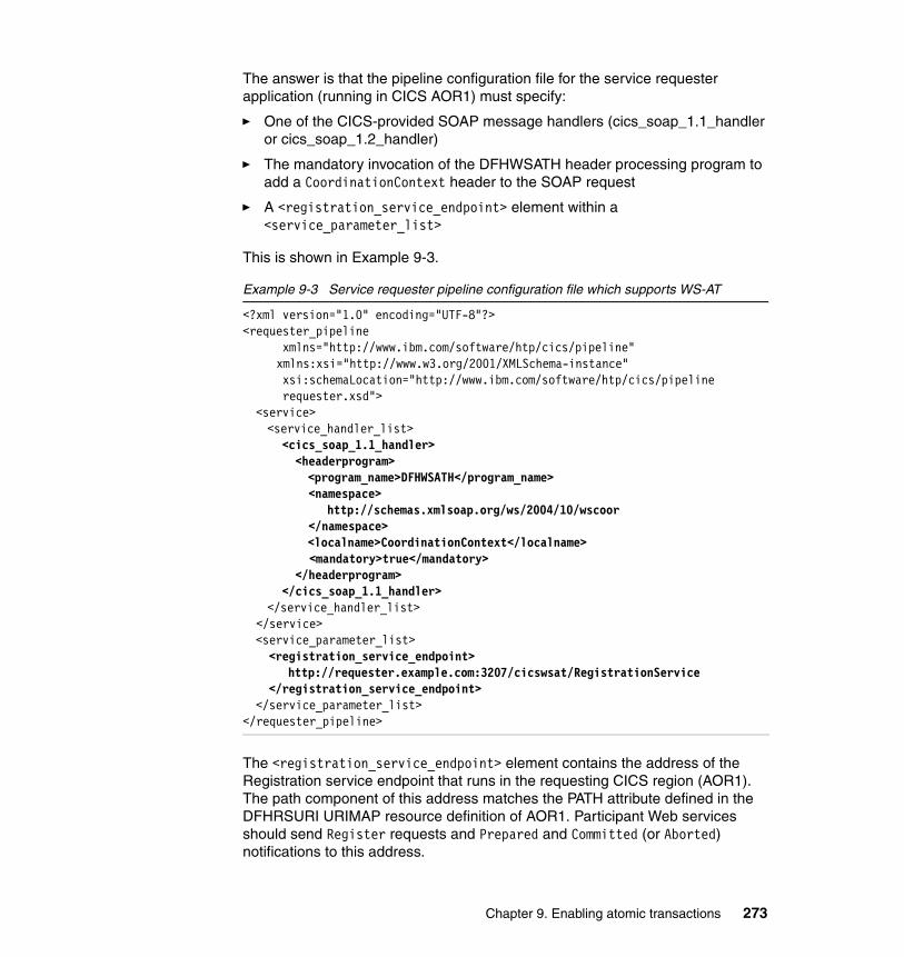
The answer is that the pipeline configuration file for the service requester application (running in CICS AOR1) must specify:
� One of the CICS-provided SOAP message handlers (cics_soap_1.1_handler or cics_soap_1.2_handler)
� The mandatory invocation of the DFHWSATH header processing program to add a CoordinationContext header to the SOAP request
� A <registration_service_endpoint> element within a <service_parameter_list>
This is shown in Example 9-3.
Example 9-3 Service requester pipeline configuration file which supports WS-AT
<?xml version="1.0" encoding="UTF-8"?> <requester_pipeline
xmlns="http://www.ibm.com/software/htp/cics/pipeline" xmlns:xsi="http://www.w3.org/2001/XMLSchema-instance" xsi:schemaLocation="http://www.ibm.com/software/htp/cics/pipeline
requester.xsd"> <service> <service_handler_list> <cics_soap_1.1_handler> <headerprogram> <program_name>DFHWSATH</program_name> <namespace> http://schemas.xmlsoap.org/ws/2004/10/wscoor </namespace> <localname>CoordinationContext</localname> <mandatory>true</mandatory> </headerprogram> </cics_soap_1.1_handler> </service_handler_list> </service> <service_parameter_list> <registration_service_endpoint> http://requester.example.com:3207/cicswsat/RegistrationService </registration_service_endpoint> </service_parameter_list> </requester_pipeline>
The <registration_service_endpoint> element contains the address of the Registration service endpoint that runs in the requesting CICS region (AOR1). The path component of this address matches the PATH attribute defined in the DFHRSURI URIMAP resource definition of AOR1. Participant Web services should send Register requests and Prepared and Committed (or Aborted) notifications to this address.
Chapter 9. Enabling atomic transactions 273
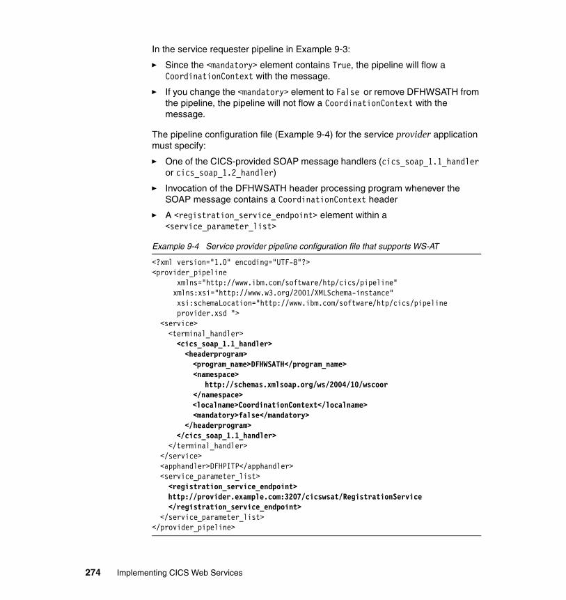
In the service requester pipeline in Example 9-3:
� Since the <mandatory> element contains True, the pipeline will flow a CoordinationContext with the message.
� If you change the <mandatory> element to False or remove DFHWSATH from the pipeline, the pipeline will not flow a CoordinationContext with the message.
The pipeline configuration file (Example 9-4) for the service provider application must specify:
� One of the CICS-provided SOAP message handlers (cics_soap_1.1_handler or cics_soap_1.2_handler)
� Invocation of the DFHWSATH header processing program whenever the SOAP message contains a CoordinationContext header
� A <registration_service_endpoint> element within a <service_parameter_list>
Example 9-4 Service provider pipeline configuration file that supports WS-AT
<?xml version="1.0" encoding="UTF-8"?> <provider_pipeline
xmlns="http://www.ibm.com/software/htp/cics/pipeline" xmlns:xsi="http://www.w3.org/2001/XMLSchema-instance" xsi:schemaLocation="http://www.ibm.com/software/htp/cics/pipeline
provider.xsd "> <service> <terminal_handler> <cics_soap_1.1_handler> <headerprogram> <program_name>DFHWSATH</program_name> <namespace> http://schemas.xmlsoap.org/ws/2004/10/wscoor </namespace> <localname>CoordinationContext</localname> <mandatory>false</mandatory> </headerprogram> </cics_soap_1.1_handler> </terminal_handler> </service> <apphandler>DFHPITP</apphandler> <service_parameter_list> <registration_service_endpoint> http://provider.example.com:3207/cicswsat/RegistrationService </registration_service_endpoint> </service_parameter_list> </provider_pipeline>
274 Implementing CICS Web Services
This time the <registration_service_endpoint> element contains the address of the Registration service endpoint that runs in the provider CICS region. The Coordinator should send RegisterResponse messages and Prepare and Commit (or Abort) notifications to this address.
In the service provider pipeline in Example 9-4:
� The pipeline will accept flows with a CoordinationContext, and such flows will be treated as part of a WS-AT transaction.
� Since the <mandatory> element contains False, the pipeline will also accept messages without a CoordinationContext but they will not be part of any WS-AT transaction.
� If you change the <mandatory> element to True, the pipeline will require that a CoordinationContext flow with the message. A Fault will be raised if a requester attempts to use the service without a CoordinationContext.
� If you remove DFHWSATH from the pipeline, the pipeline will raise a mustUnderstand fault when a CoordinationContext arrives with mustUnderstand set to True.
We conclude this section with a few remarks on the function provided by two programs in the CICS-supplied DFHWSAT group.
DFHPIRSDFHPIRS is the central component of CICS support for WS-AT. It provides the bulk of the function that is needed for registration and protocol processing. The actions that it can be called to service include the following: Register, RegisterResponse, Prepare, Prepared, Aborted, ReadOnly, Commit, Rollback, Committed, and Replay.
If DFHPIRS encounters an unrecoverable error, it abends with an abend code of APIO.
DFHWSATHWhen included in the configuration file for a Web service requester pipeline, DFHWSATH controls the processing that causes a CoordinationContext to be created and added to the SOAP message before it is sent. To do this DFHWSATH calls DFHPIAT, which finds the local netname, the unit-of-work ID (UOWID), and the value of the DTIMOUT attribute on the TRANSACTION definition for the transaction ID under which the requesting application is running. DFHPIAT also finds the endpoint address of the Registration service for the requesting region. From all of this information DFHPIAT creates a CoordinationContext.
Chapter 9. Enabling atomic transactions 275
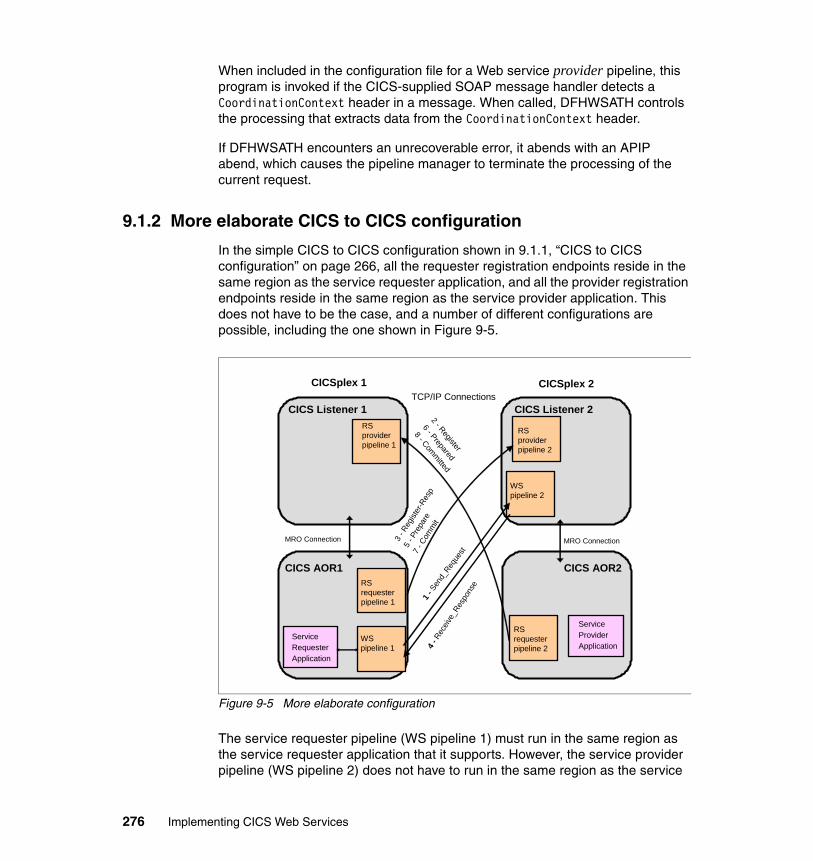
When included in the configuration file for a Web service provider pipeline, this program is invoked if the CICS-supplied SOAP message handler detects a CoordinationContext header in a message. When called, DFHWSATH controls the processing that extracts data from the CoordinationContext header.
If DFHWSATH encounters an unrecoverable error, it abends with an APIP abend, which causes the pipeline manager to terminate the processing of the current request.
9.1.2 More elaborate CICS to CICS configuration
In the simple CICS to CICS configuration shown in 9.1.1, “CICS to CICS configuration” on page 266, all the requester registration endpoints reside in the same region as the service requester application, and all the provider registration endpoints reside in the same region as the service provider application. This does not have to be the case, and a number of different configurations are possible, including the one shown in Figure 9-5.
Figure 9-5 More elaborate configuration
The service requester pipeline (WS pipeline 1) must run in the same region as the service requester application that it supports. However, the service provider pipeline (WS pipeline 2) does not have to run in the same region as the service
CICS Listener 1
CICS AOR2CICS AOR1
ServiceRequesterApplication
ServiceProviderApplication
WS pipeline 1
RS requester pipeline 2
WS pipeline 2
RS provider pipeline 2
RS provider pipeline 1
RS requester pipeline 1
MRO Connection MRO Connection3 - R
egist
er-R
esp
5 - P
repa
re7
- Com
mit
1 -Se
nd_R
eque
st
4 -Re
ceive
_Res
pons
e
2 - Register
6 - Prepared
8 - Committed
TCP/IP ConnectionsCICSplex 1 CICSplex 2
CICS Listener 2
276 Implementing CICS Web Services
provider application that it manages. Instead, these applications are eligible for dynamic routing as described in 3.4, “Configuring for high availability” on page 101. Similarly, Registration services provider pipelines, such as RS provider pipeline 1 and RS provider pipeline 2 in Figure 9-5, do not have to be located in the same region as the applications that they service.
In the case of RS provider pipeline 1, the requests arriving there are for registration with the service requester application running in AOR1, and protocol response messages that refer to this application’s role in coordinating the atomic transaction. The RS provider pipeline 2 receives registration response messages and protocol notification messages intended for the service provider application running in AOR2.
Since eventually these messages must be processed in the same region as the service provider application, the WS-AT implementation in CICS TS makes use of RequestStreams to pass these messages from one region to another. RequestStreams are dependent on MRO connections when they exchange information between CICS regions.
The use of RequestStreams means that individual Registration services provider pipelines can be used by different applications, and those applications do not have to reside in the same region. A set of cloned AORs can share a common Registration services provider pipeline that is located in a specific WS-AT CICS region. Work can then be distributed across the AORs and each of the WS-AT messages, arriving at the Registration services provider pipeline, contains sufficient information to allow it to be forwarded to the correct AOR.
Figure 9-5 shows the Registration services requester pipelines are in the same region as the applications that they service. RS requester pipeline 1 services the service requester application in AOR1, and RS requester pipeline 2 services the service provider application in AOR2. This configuration cannot be changed because CICS requires that each WS-AT message must be dispatched from the same region as the application that it relates to. This means that each AOR in a
Note: If a Registration Service provider pipeline is configured in a different region than the application that it services, then an MRO connection is required between the CICS regions.
Tip: A set of cloned AORs can share a common RS provider pipeline located in a specific WS-AT region, thus reducing the number of pipeline configurations required. In this configuration, it is recommended that you do not run applications in the specific WS-AT region and that you create clones for improved failover and availability.
Chapter 9. Enabling atomic transactions 277
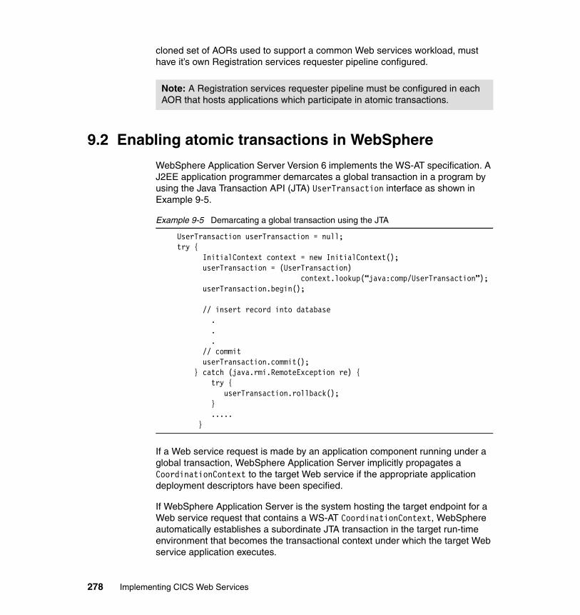
cloned set of AORs used to support a common Web services workload, must have it’s own Registration services requester pipeline configured.
9.2 Enabling atomic transactions in WebSphere
WebSphere Application Server Version 6 implements the WS-AT specification. A J2EE application programmer demarcates a global transaction in a program by using the Java Transaction API (JTA) UserTransaction interface as shown in Example 9-5.
Example 9-5 Demarcating a global transaction using the JTA
UserTransaction userTransaction = null;try {
InitialContext context = new InitialContext();userTransaction = (UserTransaction)
context.lookup(“java:comp/UserTransaction”);userTransaction.begin();
// insert record into database...
// commituserTransaction.commit();
} catch (java.rmi.RemoteException re) {try {
userTransaction.rollback(); }
.....}
If a Web service request is made by an application component running under a global transaction, WebSphere Application Server implicitly propagates a CoordinationContext to the target Web service if the appropriate application deployment descriptors have been specified.
If WebSphere Application Server is the system hosting the target endpoint for a Web service request that contains a WS-AT CoordinationContext, WebSphere automatically establishes a subordinate JTA transaction in the target run-time environment that becomes the transactional context under which the target Web service application executes.
Note: A Registration services requester pipeline must be configured in each AOR that hosts applications which participate in atomic transactions.
278 Implementing CICS Web Services
Application developers do not have to explicitly register WS-AT participants. The WebSphere Application Server run time takes responsibility for the registration of WS-AT participants. At transaction completion time, all WS-AT participants are atomically coordinated by the WebSphere Application Server transaction service.
There are no specific development tasks required for Web service applications to take advantage of WS-AT; however, there are some application deployment descriptors that have to be set appropriately:
� In a Web module that invokes a Web service, specify Send Web Services Atomic Transactions on requests to propagate the transaction to the target Web service.
See “Change the deployment descriptor” on page 296 for information on how we enabled our Web application to send WS-AT SOAP headers in requests to a CICS service provider application.
� In a Web module that implements a Web service, specify Execute using Web Services Atomic Transaction on incoming requests to run under a received client transaction context.
� In an EJB module that invokes a Web service, specify Use Web Services Atomic Transaction to propagate the EJB transaction to the target Web service.
� In an EJB module, bean methods must be specified with transaction type Required, which is the default, to participate in a global atomic transaction.
Chapter 9. Enabling atomic transactions 279

280 Implementing CICS Web Services
Chapter 10. Transaction scenarios
In this chapter we show different scenarios that demonstrate how you can synchronize resource updates using the WS-Atomic Transaction support in CICS and WebSphere Application Server.
We start with an explanation of the scenarios that we set out to test, and how we prepared the system and the settings that we used for the configuration of our system.
We then cover in detail the changes that we made to the CICS pipeline configuration and WebSphere Application Server to enable Web services transactional integration.
10
© Copyright IBM Corp. 2006. All rights reserved. 281

10.1 Introduction to our scenarios
Figure 10-1 shows three different atomic transaction scenarios that we considered testing.
Figure 10-1 Three possible atomic transaction scenarios
The scenario at the top is the simple case where a coordinator controls a single participant. Both parties may make recoverable updates. Another possibility is that only the participant makes recoverable updates. A third possibility is that the participant does nothing recoverable; in this case it will send a ReadOnly notification when it is coordinated.
The second scenario is often referred to as a daisy chain. Here there is a primary (or root) coordinator that invokes a Web service, and the invoked Web service then invokes a second Web service. The entire atomic transaction is controlled by the primary coordinator. The middle system takes on the role of a coordinator and the role of a participant at different times in its life cycle. When the primary coordinator instructs it during transaction termination, this system acts as a participant. However, before it responds to the primary coordinator, it then takes on the role of coordinator of its own participant.
The third scenario is a hub configuration. A single coordinator invokes one Web service and then another. It then coordinates them together.
Participant
Coordinator
ParticipantCoordinator
Participant
Participant/Coordinator
Coordinator Participant
Hub
Simple
Daisychain
282 Implementing CICS Web Services
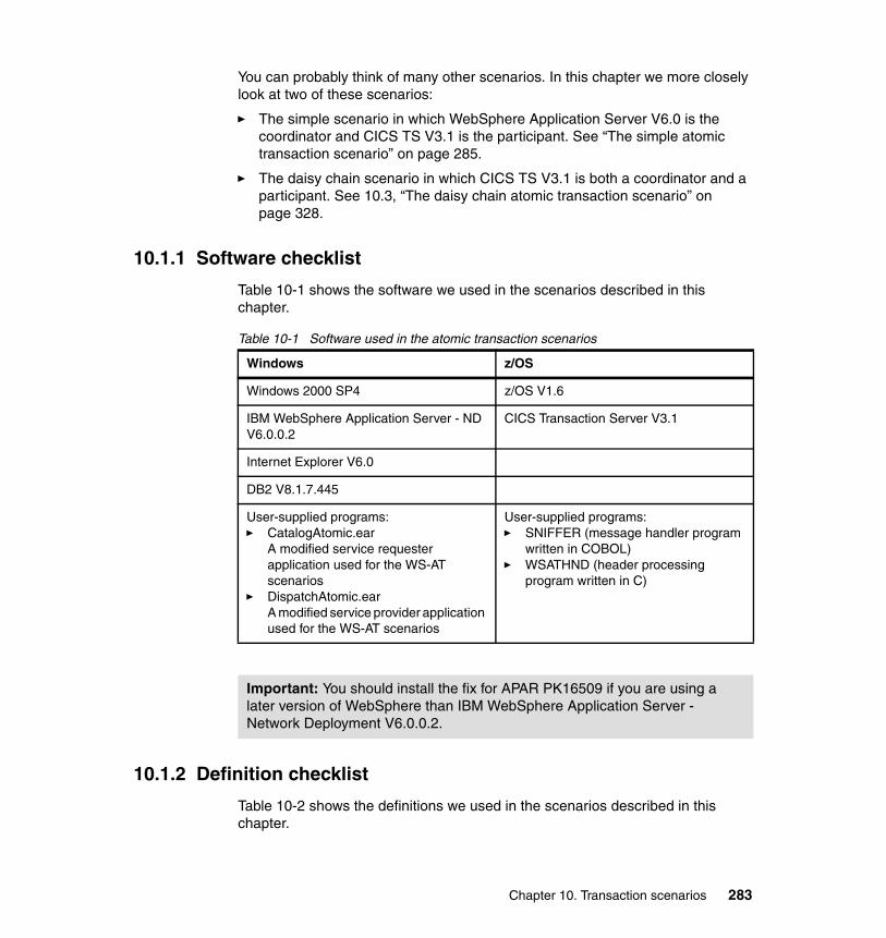
You can probably think of many other scenarios. In this chapter we more closely look at two of these scenarios:
� The simple scenario in which WebSphere Application Server V6.0 is the coordinator and CICS TS V3.1 is the participant. See “The simple atomic transaction scenario” on page 285.
� The daisy chain scenario in which CICS TS V3.1 is both a coordinator and a participant. See 10.3, “The daisy chain atomic transaction scenario” on page 328.
10.1.1 Software checklist
Table 10-1 shows the software we used in the scenarios described in this chapter.
Table 10-1 Software used in the atomic transaction scenarios
10.1.2 Definition checklist
Table 10-2 shows the definitions we used in the scenarios described in this chapter.
Windows z/OS
Windows 2000 SP4 z/OS V1.6
IBM WebSphere Application Server - ND V6.0.0.2
CICS Transaction Server V3.1
Internet Explorer V6.0
DB2 V8.1.7.445
User-supplied programs:� CatalogAtomic.ear
A modified service requester application used for the WS-AT scenarios
� DispatchAtomic.earA modified service provider application used for the WS-AT scenarios
User-supplied programs:� SNIFFER (message handler program
written in COBOL)� WSATHND (header processing
program written in C)
Important: You should install the fix for APAR PK16509 if you are using a later version of WebSphere than IBM WebSphere Application Server - Network Deployment V6.0.0.2.
Chapter 10. Transaction scenarios 283
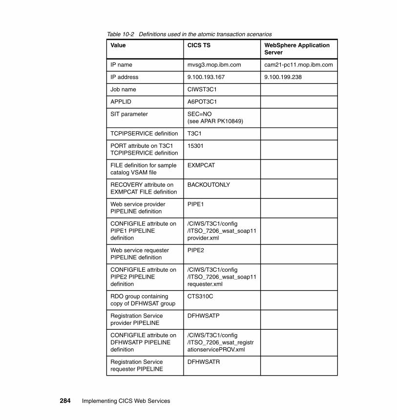
Table 10-2 Definitions used in the atomic transaction scenarios
Value CICS TS WebSphere Application Server
IP name mvsg3.mop.ibm.com cam21-pc11.mop.ibm.com
IP address 9.100.193.167 9.100.199.238
Job name CIWST3C1
APPLID A6POT3C1
SIT parameter SEC=NO(see APAR PK10849)
TCPIPSERVICE definition T3C1
PORT attribute on T3C1 TCPIPSERVICE definition
15301
FILE definition for sample catalog VSAM file
EXMPCAT
RECOVERY attribute on EXMPCAT FILE definition
BACKOUTONLY
Web service provider PIPELINE definition
PIPE1
CONFIGFILE attribute on PIPE1 PIPELINEdefinition
/CIWS/T3C1/config/ITSO_7206_wsat_soap11provider.xml
Web service requester PIPELINE definition
PIPE2
CONFIGFILE attribute on PIPE2 PIPELINEdefinition
/CIWS/T3C1/config/ITSO_7206_wsat_soap11requester.xml
RDO group containing copy of DFHWSAT group
CTS310C
Registration Service provider PIPELINE
DFHWSATP
CONFIGFILE attribute on DFHWSATP PIPELINE definition
/CIWS/T3C1/config/ITSO_7206_wsat_registrationservicePROV.xml
Registration Service requester PIPELINE
DFHWSATR
284 Implementing CICS Web Services
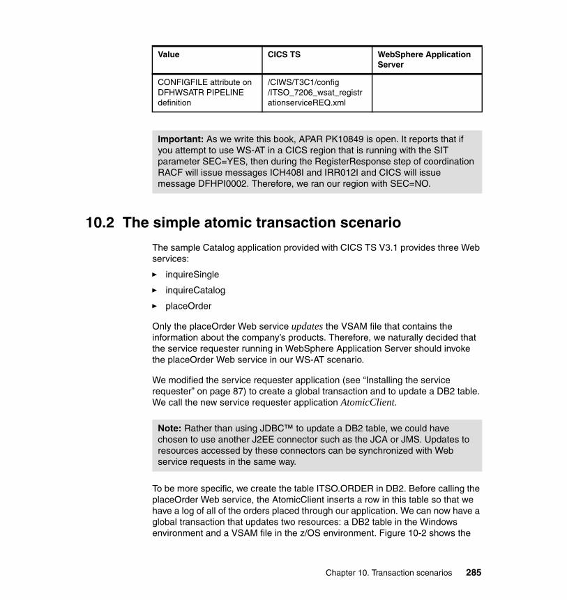
10.2 The simple atomic transaction scenario
The sample Catalog application provided with CICS TS V3.1 provides three Web services:
� inquireSingle
� inquireCatalog
� placeOrder
Only the placeOrder Web service updates the VSAM file that contains the information about the company’s products. Therefore, we naturally decided that the service requester running in WebSphere Application Server should invoke the placeOrder Web service in our WS-AT scenario.
We modified the service requester application (see “Installing the service requester” on page 87) to create a global transaction and to update a DB2 table. We call the new service requester application AtomicClient.
To be more specific, we create the table ITSO.ORDER in DB2. Before calling the placeOrder Web service, the AtomicClient inserts a row in this table so that we have a log of all of the orders placed through our application. We can now have a global transaction that updates two resources: a DB2 table in the Windows environment and a VSAM file in the z/OS environment. Figure 10-2 shows the
CONFIGFILE attribute on DFHWSATR PIPELINE definition
/CIWS/T3C1/config/ITSO_7206_wsat_registrationserviceREQ.xml
Important: As we write this book, APAR PK10849 is open. It reports that if you attempt to use WS-AT in a CICS region that is running with the SIT parameter SEC=YES, then during the RegisterResponse step of coordination RACF will issue messages ICH408I and IRR012I and CICS will issue message DFHPI0002. Therefore, we ran our region with SEC=NO.
Value CICS TS WebSphere Application Server
Note: Rather than using JDBC™ to update a DB2 table, we could have chosen to use another J2EE connector such as the JCA or JMS. Updates to resources accessed by these connectors can be synchronized with Web service requests in the same way.
Chapter 10. Transaction scenarios 285
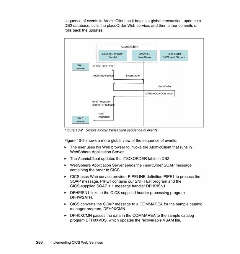
sequence of events in AtomicClient as it begins a global transaction, updates a DB2 database, calls the placeOrder Web service, and then either commits or rolls back the updates.
Figure 10-2 Simple atomic transaction sequence of events
Figure 10-3 shows a more global view of the sequence of events:
� The user uses his Web browser to invoke the AtomicClient that runs in WebSphere Application Server.
� The AtomicClient updates the ITSO.ORDER table in DB2.
� WebSphere Application Server sends the insertOrder SOAP message containing the order to CICS.
� CICS uses Web service provider PIPELINE definition PIPE1 to process the SOAP message. PIPE1 contains our SNIFFER program and the CICS-supplied SOAP 1.1 message handler DFHPISN1.
� DFHPISN1 links to the CICS-supplied header processing program DFHWSATH.
� CICS converts the SOAP message to a COMMAREA for the sample catalog manager program, DFH0XCMN.
� DFH0XCMN passes the data in the COMMAREA to the sample catalog program DFH0XVDS, which updates the recoverable VSAM file.
CatalogControllerServlet
OrderDBJava Bean
Place OrderCICS Web Service
handlePlaceOrder
insertOrder
placeOrder
DFH0XCMNOperation
beginTransaction
endTransactioncommit or rollback
sendresponse
Web browser
Web browser
AtomicClient
286 Implementing CICS Web Services
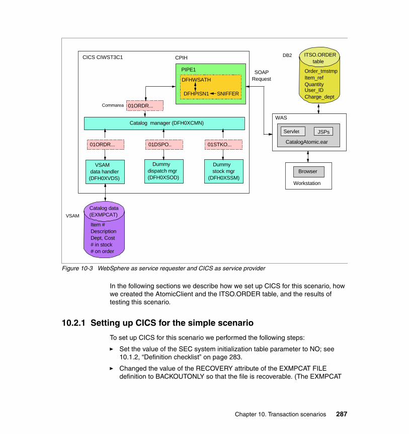
Figure 10-3 WebSphere as service requester and CICS as service provider
In the following sections we describe how we set up CICS for this scenario, how we created the AtomicClient and the ITSO.ORDER table, and the results of testing this scenario.
10.2.1 Setting up CICS for the simple scenario
To set up CICS for this scenario we performed the following steps:
� Set the value of the SEC system initialization table parameter to NO; see 10.1.2, “Definition checklist” on page 283.
� Changed the value of the RECOVERY attribute of the EXMPCAT FILE definition to BACKOUTONLY so that the file is recoverable. (The EXMPCAT
Servlet JSPs
CatalogAtomic.ear
CICS CIWST3C1
SOAPRequest
PIPE1
DB2
Catalog data(EXMPCAT)
Item #DescriptionDept, Cost# in stock# on order
Catalog manager (DFH0XCMN)
01ORDR...
Workstation
Browser
WAS
Dummy stock mgr (DFH0XSSM)
VSAM data handler(DFH0XVDS)
Dummy dispatch mgr (DFH0XSOD)
01ORDR... 01DSPO.. 01STKO...
DFHWSATH
CPIH
DFHPISN1 SNIFFER
Commarea
ITSO.ORDER table
Order_tmstmpItem_refQuantity User_IDCharge_dept
VSAM
Chapter 10. Transaction scenarios 287
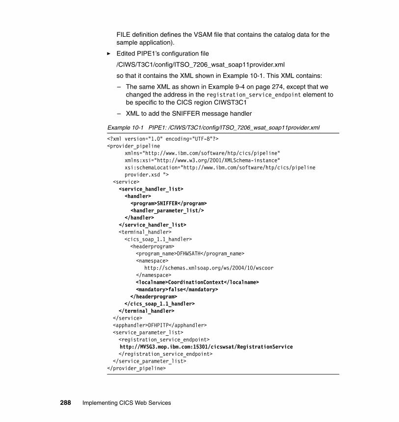
FILE definition defines the VSAM file that contains the catalog data for the sample application).
� Edited PIPE1’s configuration file
/CIWS/T3C1/config/ITSO_7206_wsat_soap11provider.xml
so that it contains the XML shown in Example 10-1. This XML contains:
– The same XML as shown in Example 9-4 on page 274, except that we changed the address in the registration_service_endpoint element to be specific to the CICS region CIWST3C1
– XML to add the SNIFFER message handler
Example 10-1 PIPE1: /CIWS/T3C1/config/ITSO_7206_wsat_soap11provider.xml
<?xml version="1.0" encoding="UTF-8"?> <provider_pipeline
xmlns="http://www.ibm.com/software/htp/cics/pipeline" xmlns:xsi="http://www.w3.org/2001/XMLSchema-instance" xsi:schemaLocation="http://www.ibm.com/software/htp/cics/pipeline provider.xsd ">
<service> <service_handler_list> <handler> <program>SNIFFER</program> <handler_parameter_list/> </handler> </service_handler_list> <terminal_handler> <cics_soap_1.1_handler> <headerprogram> <program_name>DFHWSATH</program_name> <namespace> http://schemas.xmlsoap.org/ws/2004/10/wscoor </namespace> <localname>CoordinationContext</localname> <mandatory>false</mandatory> </headerprogram> </cics_soap_1.1_handler> </terminal_handler> </service> <apphandler>DFHPITP</apphandler> <service_parameter_list> <registration_service_endpoint> http://MVSG3.mop.ibm.com:15301/cicswsat/RegistrationService </registration_service_endpoint> </service_parameter_list> </provider_pipeline>
288 Implementing CICS Web Services
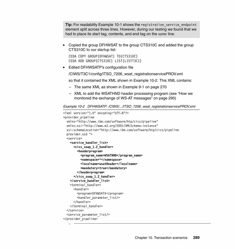
� Copied the group DFHWSAT to the group CTS310C and added the group CTS310C to our startup list:
CEDA COPY GROUP(DFHWSAT) TO(CTS310C)CEDA ADD GROUP(CTS310C) LIST(LISTT3C1)
� Edited DFHWSATP’s configuration file
/CIWS/T3C1/config/ITSO_7206_wsat_registrationservicePROV.xml
so that it contained the XML shown in Example 10-2. This XML contains:
– The same XML as shown in Example 9-1 on page 270
– XML to add the WSATHND header processing program (see “How we monitored the exchange of WS-AT messages” on page 290)
Example 10-2 DFHWSATP: /CIWS/.../ITSO_7206_wsat_registrationservicePROV.xml
<?xml version="1.0" encoding="UTF-8"?> <provider_pipeline xmlns="http://www.ibm.com/software/htp/cics/pipeline"
xmlns:xsi="http://www.w3.org/2001/XMLSchema-instance" xsi:schemaLocation="http://www.ibm.com/software/htp/cics/pipeline provider.xsd ">
<service><service_handler_list>
<cics_soap_1.2_handler> <headerprogram> <program_name>WSATHND</program_name> <namespace>*</namespace> <localname>wsatHeader</localname> <mandatory>true</mandatory> </headerprogram> </cics_soap_1.2_handler> </service_handler_list> <terminal_handler> <handler> <program>DFHWSATX</program> <handler_parameter_list/> </handler> </terminal_handler> </service> <service_parameter_list/> </provider_pipeline>
–
Tip: For readability Example 10-1 shows the registration_service_endpoint element split across three lines. However, during our testing we found that we had to place its start tag, contents, and end tag on the same line.
Chapter 10. Transaction scenarios 289
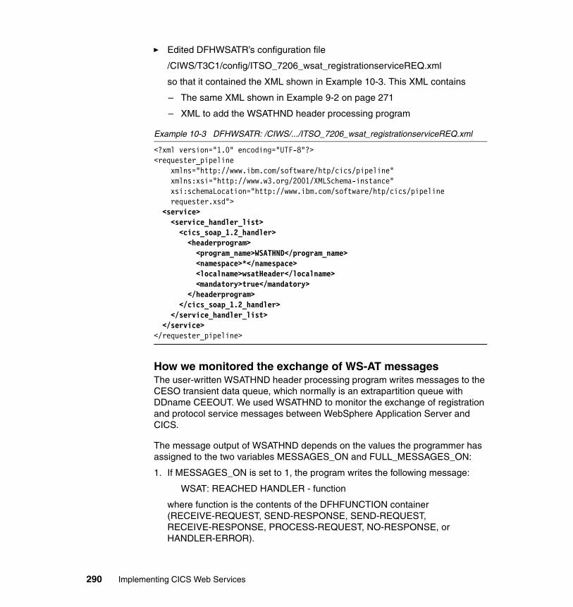
� Edited DFHWSATR’s configuration file
/CIWS/T3C1/config/ITSO_7206_wsat_registrationserviceREQ.xml
so that it contained the XML shown in Example 10-3. This XML contains
– The same XML shown in Example 9-2 on page 271
– XML to add the WSATHND header processing program
Example 10-3 DFHWSATR: /CIWS/.../ITSO_7206_wsat_registrationserviceREQ.xml
<?xml version="1.0" encoding="UTF-8"?> <requester_pipeline
xmlns="http://www.ibm.com/software/htp/cics/pipeline" xmlns:xsi="http://www.w3.org/2001/XMLSchema-instance" xsi:schemaLocation="http://www.ibm.com/software/htp/cics/pipeline requester.xsd">
<service> <service_handler_list> <cics_soap_1.2_handler> <headerprogram> <program_name>WSATHND</program_name> <namespace>*</namespace> <localname>wsatHeader</localname> <mandatory>true</mandatory> </headerprogram> </cics_soap_1.2_handler> </service_handler_list> </service> </requester_pipeline>
How we monitored the exchange of WS-AT messagesThe user-written WSATHND header processing program writes messages to the CESO transient data queue, which normally is an extrapartition queue with DDname CEEOUT. We used WSATHND to monitor the exchange of registration and protocol service messages between WebSphere Application Server and CICS.
The message output of WSATHND depends on the values the programmer has assigned to the two variables MESSAGES_ON and FULL_MESSAGES_ON:
1. If MESSAGES_ON is set to 1, the program writes the following message:
WSAT: REACHED HANDLER - function
where function is the contents of the DFHFUNCTION container (RECEIVE-REQUEST, SEND-RESPONSE, SEND-REQUEST, RECEIVE-RESPONSE, PROCESS-REQUEST, NO-RESPONSE, or HANDLER-ERROR).
290 Implementing CICS Web Services
When the function is NO-RESPONSE, then the handler is being invoked after processing a request, when there is no response to be processed.
2. If the function is not NO-RESPONSE, then:
– If FULL_MESSAGES_ON is set to 1, WSATHND writes the following message:
WSAT: contents of the DFHREQUEST container
– If MESSAGES_ON is set to 1, it will write the following message:
WSAT: ACTION: action
where action has one of the following values: Register, RegisterResponse, Prepare, Prepared, Commit, Committed, ReadOnly, Abort, Aborted, Rollback.
Thus, WSATHND provides a way to see the registration and protocol service messages that are being sent between the service requester and the service provider as they happen. We found it easier to use this program than to take a TCP/IP trace or to search for these messages in a CICS auxiliary trace. The full WSATHND program is shown A.7, “Sample header processing program - WSATHND” on page 385.
10.2.2 Creating the AtomicClient and ITSO.ORDER table
To create the AtomicClient and the ITSO.ORDER table, we did the following:
� Created the OrderBean JavaBean that represents the order.
� Created the OrderDB JavaBean that inserts the order into the DB2 database.
� Changed the handlePlaceOrder method of the CatalogController servlet so that it creates an OrderBean and then calls OrderDB to insert it into the DB2 database as part of a global transaction.
� Changed the deployment descriptor of the Web module CatalogAtomicWeb. This is the module that invokes the Web Service.
� Created the ITSO.ORDER table.
� Created a data source.
We explain each step in detail in the following sections.
Create the OrderBean JavaBeanThe OrderBean JavaBean represents the order; it has all the fields from the PlaceOrder JavaServer™ Page (JSP™) plus a timestamp that records the time when the Web browser user placed the order. Example 10-4 shows the code for the OrderBean JavaBean.
Chapter 10. Transaction scenarios 291
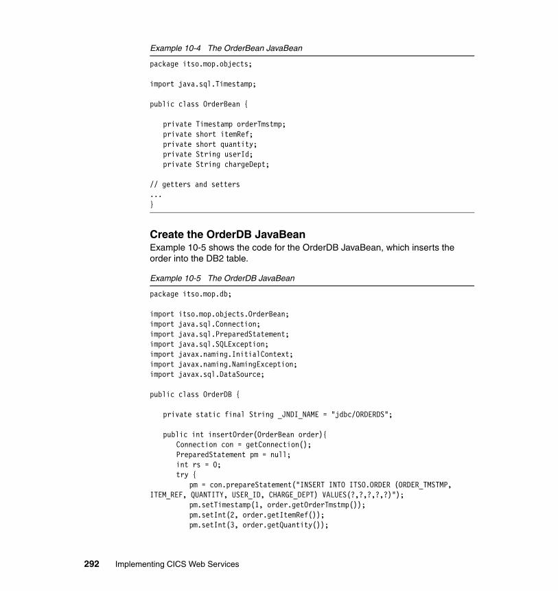
Example 10-4 The OrderBean JavaBean
package itso.mop.objects;
import java.sql.Timestamp;
public class OrderBean {
private Timestamp orderTmstmp;private short itemRef;private short quantity;private String userId;private String chargeDept;
// getters and setters...}
Create the OrderDB JavaBeanExample 10-5 shows the code for the OrderDB JavaBean, which inserts the order into the DB2 table.
Example 10-5 The OrderDB JavaBean
package itso.mop.db;
import itso.mop.objects.OrderBean;import java.sql.Connection;import java.sql.PreparedStatement;import java.sql.SQLException;import javax.naming.InitialContext;import javax.naming.NamingException;import javax.sql.DataSource;
public class OrderDB {
private static final String _JNDI_NAME = "jdbc/ORDERDS";
public int insertOrder(OrderBean order){Connection con = getConnection();PreparedStatement pm = null;int rs = 0;try {
pm = con.prepareStatement("INSERT INTO ITSO.ORDER (ORDER_TMSTMP, ITEM_REF, QUANTITY, USER_ID, CHARGE_DEPT) VALUES(?,?,?,?,?)");
pm.setTimestamp(1, order.getOrderTmstmp());pm.setInt(2, order.getItemRef());pm.setInt(3, order.getQuantity());
292 Implementing CICS Web Services
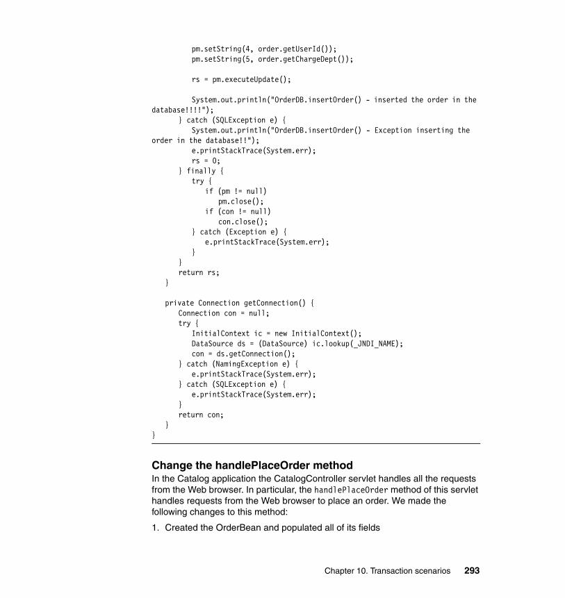
pm.setString(4, order.getUserId());pm.setString(5, order.getChargeDept());
rs = pm.executeUpdate();
System.out.println("OrderDB.insertOrder() - inserted the order in the database!!!!");
} catch (SQLException e) {System.out.println("OrderDB.insertOrder() - Exception inserting the
order in the database!!");e.printStackTrace(System.err);rs = 0;
} finally {try {
if (pm != null)pm.close();
if (con != null)con.close();
} catch (Exception e) {e.printStackTrace(System.err);
}}return rs;
}
private Connection getConnection() {Connection con = null;try {
InitialContext ic = new InitialContext();DataSource ds = (DataSource) ic.lookup(_JNDI_NAME);con = ds.getConnection();
} catch (NamingException e) {e.printStackTrace(System.err);
} catch (SQLException e) {e.printStackTrace(System.err);
}return con;
}}
Change the handlePlaceOrder methodIn the Catalog application the CatalogController servlet handles all the requests from the Web browser. In particular, the handlePlaceOrder method of this servlet handles requests from the Web browser to place an order. We made the following changes to this method:
1. Created the OrderBean and populated all of its fields
Chapter 10. Transaction scenarios 293
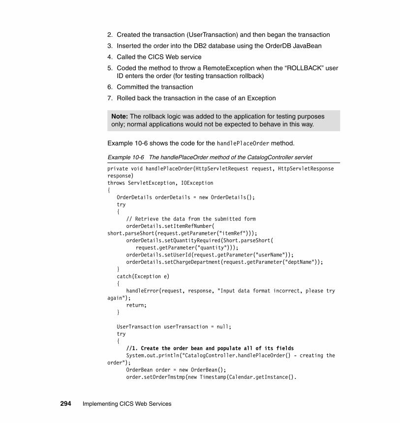
2. Created the transaction (UserTransaction) and then began the transaction
3. Inserted the order into the DB2 database using the OrderDB JavaBean
4. Called the CICS Web service
5. Coded the method to throw a RemoteException when the “ROLLBACK” user ID enters the order (for testing transaction rollback)
6. Committed the transaction
7. Rolled back the transaction in the case of an Exception
Example 10-6 shows the code for the handlePlaceOrder method.
Example 10-6 The handlePlaceOrder method of the CatalogController servlet
private void handlePlaceOrder(HttpServletRequest request, HttpServletResponse response)throws ServletException, IOException{
OrderDetails orderDetails = new OrderDetails();try{
// Retrieve the data from the submitted formorderDetails.setItemRefNumber(
short.parseShort(request.getParameter("itemRef")));orderDetails.setQuantityRequired(Short.parseShort(
request.getParameter("quantity")));orderDetails.setUserId(request.getParameter("userName"));orderDetails.setChargeDepartment(request.getParameter("deptName"));
}catch(Exception e){
handleError(request, response, "Input data format incorrect, please try again");
return;}
UserTransaction userTransaction = null;try{
//1. Create the order bean and populate all of its fieldsSystem.out.println("CatalogController.handlePlaceOrder() - creating the
order");OrderBean order = new OrderBean();order.setOrderTmstmp(new Timestamp(Calendar.getInstance().
Note: The rollback logic was added to the application for testing purposes only; normal applications would not be expected to behave in this way.
294 Implementing CICS Web Services
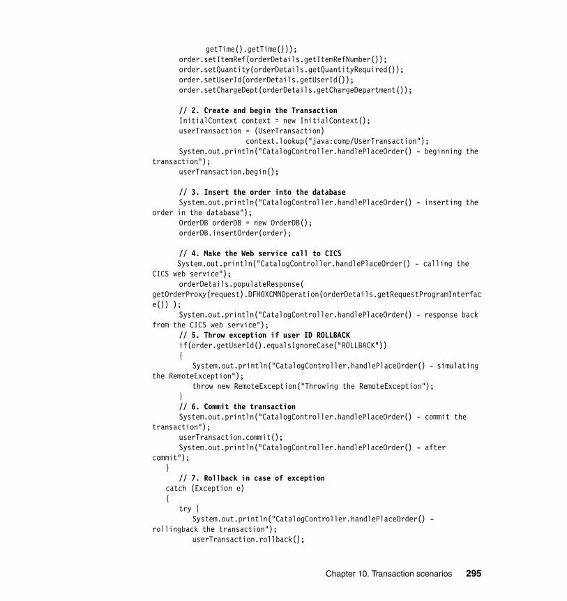
getTime().getTime()));order.setItemRef(orderDetails.getItemRefNumber());order.setQuantity(orderDetails.getQuantityRequired());order.setUserId(orderDetails.getUserId());order.setChargeDept(orderDetails.getChargeDepartment());
// 2. Create and begin the TransactionInitialContext context = new InitialContext();userTransaction = (UserTransaction)
context.lookup("java:comp/UserTransaction");System.out.println("CatalogController.handlePlaceOrder() - beginning the
transaction");userTransaction.begin();
// 3. Insert the order into the databaseSystem.out.println("CatalogController.handlePlaceOrder() - inserting the
order in the database");OrderDB orderDB = new OrderDB();orderDB.insertOrder(order);
// 4. Make the Web service call to CICS System.out.println("CatalogController.handlePlaceOrder() - calling the
CICS web service");orderDetails.populateResponse(
getOrderProxy(request).DFH0XCMNOperation(orderDetails.getRequestProgramInterface()) );
System.out.println("CatalogController.handlePlaceOrder() - response back from the CICS web service");
// 5. Throw exception if user ID ROLLBACKif(order.getUserId().equalsIgnoreCase("ROLLBACK")){
System.out.println("CatalogController.handlePlaceOrder() - simulating the RemoteException");
throw new RemoteException("Throwing the RemoteException");}// 6. Commit the transactionSystem.out.println("CatalogController.handlePlaceOrder() - commit the
transaction");userTransaction.commit();System.out.println("CatalogController.handlePlaceOrder() - after
commit");}
// 7. Rollback in case of exceptioncatch (Exception e){
try {System.out.println("CatalogController.handlePlaceOrder() -
rollingback the transaction");userTransaction.rollback();
Chapter 10. Transaction scenarios 295
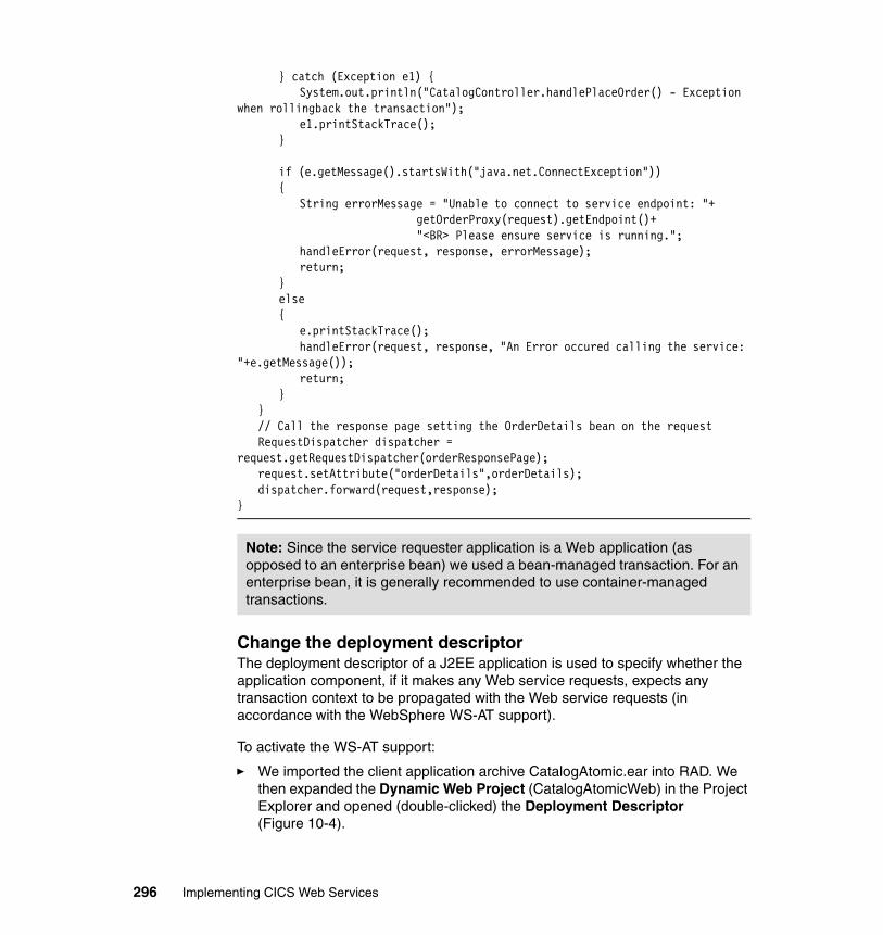
} catch (Exception e1) {System.out.println("CatalogController.handlePlaceOrder() - Exception
when rollingback the transaction");e1.printStackTrace();
}
if (e.getMessage().startsWith("java.net.ConnectException")){
String errorMessage = "Unable to connect to service endpoint: "+ getOrderProxy(request).getEndpoint()+ "<BR> Please ensure service is running.";
handleError(request, response, errorMessage);return;
}else{
e.printStackTrace();handleError(request, response, "An Error occured calling the service:
"+e.getMessage());return;
}}// Call the response page setting the OrderDetails bean on the requestRequestDispatcher dispatcher =
request.getRequestDispatcher(orderResponsePage);request.setAttribute("orderDetails",orderDetails);dispatcher.forward(request,response);
}
Change the deployment descriptorThe deployment descriptor of a J2EE application is used to specify whether the application component, if it makes any Web service requests, expects any transaction context to be propagated with the Web service requests (in accordance with the WebSphere WS-AT support).
To activate the WS-AT support:
� We imported the client application archive CatalogAtomic.ear into RAD. We then expanded the Dynamic Web Project (CatalogAtomicWeb) in the Project Explorer and opened (double-clicked) the Deployment Descriptor (Figure 10-4).
Note: Since the service requester application is a Web application (as opposed to an enterprise bean) we used a bean-managed transaction. For an enterprise bean, it is generally recommended to use container-managed transactions.
296 Implementing CICS Web Services
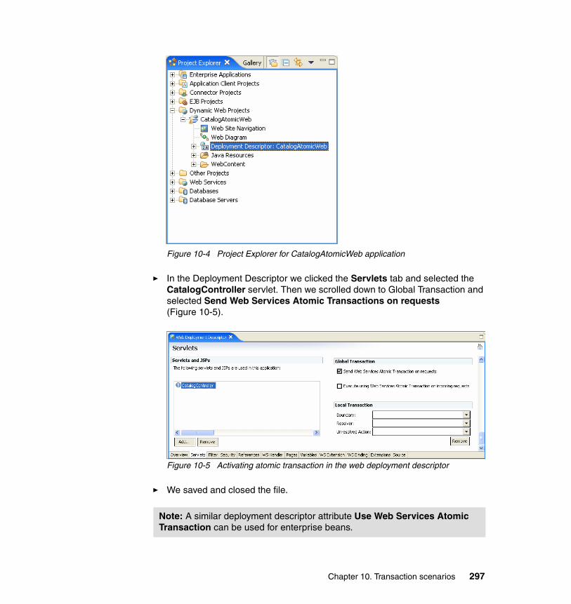
Figure 10-4 Project Explorer for CatalogAtomicWeb application
� In the Deployment Descriptor we clicked the Servlets tab and selected the CatalogController servlet. Then we scrolled down to Global Transaction and selected Send Web Services Atomic Transactions on requests (Figure 10-5).
Figure 10-5 Activating atomic transaction in the web deployment descriptor
� We saved and closed the file.
Note: A similar deployment descriptor attribute Use Web Services Atomic Transaction can be used for enterprise beans.
Chapter 10. Transaction scenarios 297
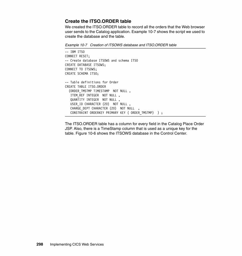
Create the ITSO.ORDER tableWe created the ITSO.ORDER table to record all the orders that the Web browser user sends to the Catalog application. Example 10-7 shows the script we used to create the database and the table.
Example 10-7 Creation of ITSOWS database and ITSO.ORDER table
-- IBM ITSO CONNECT RESET;-- Create database ITSOWS and schema ITSOCREATE DATABASE ITSOWS;CONNECT TO ITSOWS;CREATE SCHEMA ITSO;
-- Table definitions for OrderCREATE TABLE ITSO.ORDER (ORDER_TMSTMP TIMESTAMP NOT NULL , ITEM_REF INTEGER NOT NULL , QUANTITY INTEGER NOT NULL , USER_ID CHARACTER (20) NOT NULL , CHARGE_DEPT CHARACTER (20) NOT NULL , CONSTRAINT ORDERKEY PRIMARY KEY ( ORDER_TMSTMP) ) ;
The ITSO.ORDER table has a column for every field in the Catalog Place Order JSP. Also, there is a TimeStamp column that is used as a unique key for the table. Figure 10-6 shows the ITSOWS database in the Control Center.
298 Implementing CICS Web Services
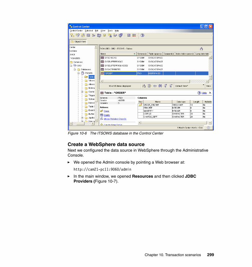
Figure 10-6 The ITSOWS database in the Control Center
Create a WebSphere data source Next we configured the data source in WebSphere through the Administrative Console.
� We opened the Admin console by pointing a Web browser at:
http://cam21-pc11:9060/admin
� In the main window, we opened Resources and then clicked JDBC Providers (Figure 10-7).
Chapter 10. Transaction scenarios 299
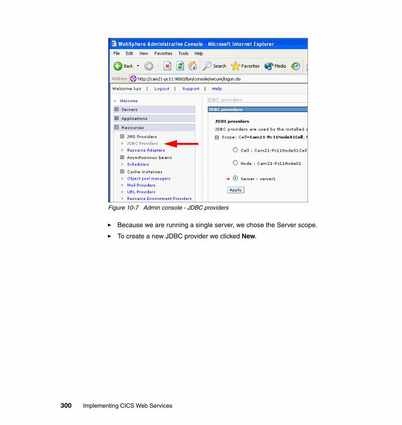
Figure 10-7 Admin console - JDBC providers
� Because we are running a single server, we chose the Server scope.
� To create a new JDBC provider we clicked New.
300 Implementing CICS Web Services
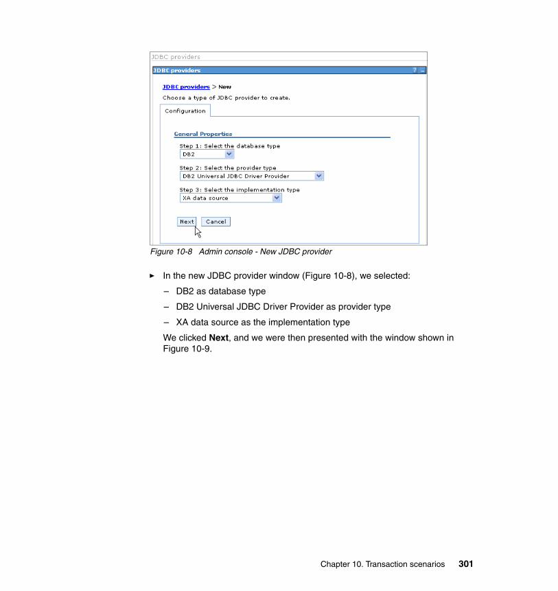
Figure 10-8 Admin console - New JDBC provider
� In the new JDBC provider window (Figure 10-8), we selected:
– DB2 as database type
– DB2 Universal JDBC Driver Provider as provider type
– XA data source as the implementation type
We clicked Next, and we were then presented with the window shown in Figure 10-9.
Chapter 10. Transaction scenarios 301
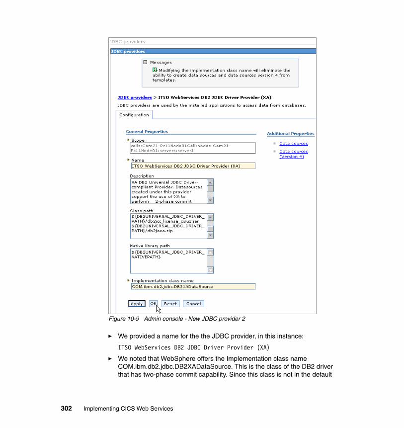
Figure 10-9 Admin console - New JDBC provider 2
� We provided a name for the the JDBC provider, in this instance:
ITSO WebServices DB2 JDBC Driver Provider (XA)
� We noted that WebSphere offers the Implementation class name COM.ibm.db2.jdbc.DB2XADataSource. This is the class of the DB2 driver that has two-phase commit capability. Since this class is not in the default
302 Implementing CICS Web Services
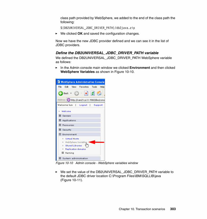
class path provided by WebSphere, we added to the end of the class path the following:
${DB2UNIVERSAL_JDBC_DRIVER_PATH}/db2java.zip
� We clicked OK and saved the configuration changes.
Now we have the new JDBC provider defined and we can see it in the list of JDBC providers.
Define the DB2UNIVERSAL_JDBC_DRIVER_PATH variableWe defined the DB2UNIVERSAL_JDBC_DRIVER_PATH WebSphere variable as follows:
� In the Admin console main window we clicked Environment and then clicked WebSphere Variables as shown in Figure 10-10.
Figure 10-10 Admin console - WebSphere variables window
� We set the value of the DB2UNIVERSAL_JDBC_DRIVER_PATH variable to the default JDBC driver location C:\Program Files\IBM\SQLLIB\java (Figure 10-11).
Chapter 10. Transaction scenarios 303
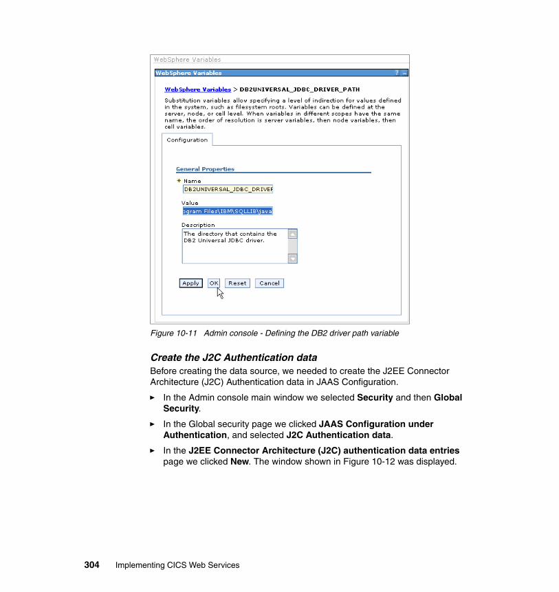
Figure 10-11 Admin console - Defining the DB2 driver path variable
Create the J2C Authentication dataBefore creating the data source, we needed to create the J2EE Connector Architecture (J2C) Authentication data in JAAS Configuration.
� In the Admin console main window we selected Security and then Global Security.
� In the Global security page we clicked JAAS Configuration under Authentication, and selected J2C Authentication data.
� In the J2EE Connector Architecture (J2C) authentication data entries page we clicked New. The window shown in Figure 10-12 was displayed.
304 Implementing CICS Web Services
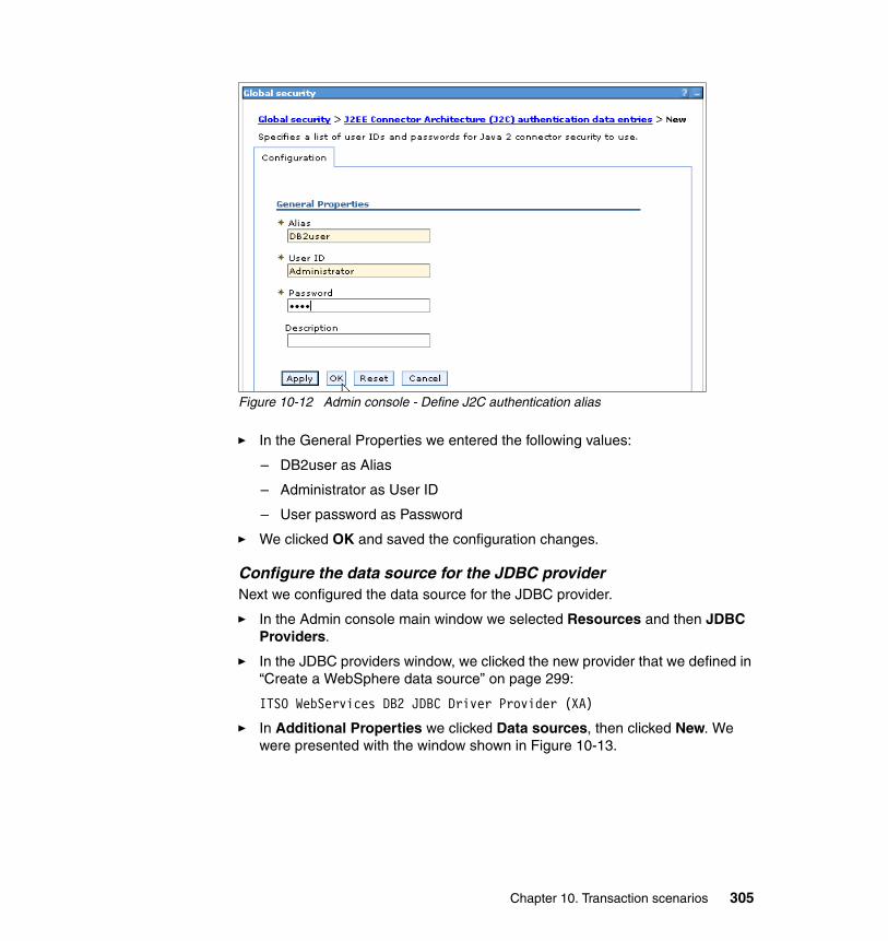
Figure 10-12 Admin console - Define J2C authentication alias
� In the General Properties we entered the following values:
– DB2user as Alias
– Administrator as User ID
– User password as Password
� We clicked OK and saved the configuration changes.
Configure the data source for the JDBC providerNext we configured the data source for the JDBC provider.
� In the Admin console main window we selected Resources and then JDBC Providers.
� In the JDBC providers window, we clicked the new provider that we defined in “Create a WebSphere data source” on page 299:
ITSO WebServices DB2 JDBC Driver Provider (XA)
� In Additional Properties we clicked Data sources, then clicked New. We were presented with the window shown in Figure 10-13.
Chapter 10. Transaction scenarios 305
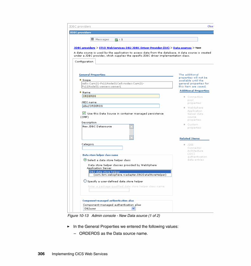
Figure 10-13 Admin console - New Data source (1 of 2)
� In the General Properties we entered the following values:
– ORDERDS as the Data source name.
306 Implementing CICS Web Services
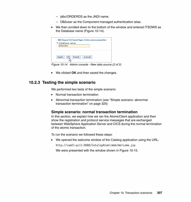
– jdbc/ORDERDS as the JNDI name.
– DB2user as the Component-managed authentication alias.
� We then scrolled down to the bottom of the window and entered ITSOWS as the Database name (Figure 10-14).
Figure 10-14 Admin console - New data source (2 of 2)
� We clicked OK and then saved the changes.
10.2.3 Testing the simple scenario
We performed two tests of the simple scenario:
� Normal transaction termination
� Abnormal transaction termination (see “Simple scenario: abnormal transaction termination” on page 325)
Simple scenario: normal transaction terminationIn this section, we explain how we ran the AtomicClient application and then show the registration and protocol service messages that are exchanged between WebSphere Application Server and CICS during the normal termination of the atomic transaction.
To run the scenario we followed these steps:
� We opened the welcome window of the Catalog application using the URL:
http://cam21-pc11:9080/CatalogAtomicWeb/Welcome.jsp
We were presented with the window shown in Figure 10-15.
Chapter 10. Transaction scenarios 307
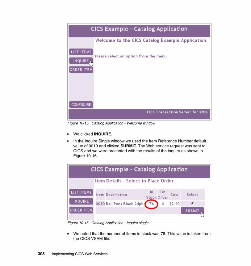
Figure 10-15 Catalog Application - Welcome window
� We clicked INQUIRE.
� In the Inquire Single window we used the Item Reference Number default value of 0010 and clicked SUBMIT. The Web service request was sent to CICS and we were presented with the results of the inquiry as shown in Figure 10-16.
Figure 10-16 Catalog Application - Inquire single
� We noted that the number of items in stock was 76. This value is taken from the CICS VSAM file.
308 Implementing CICS Web Services
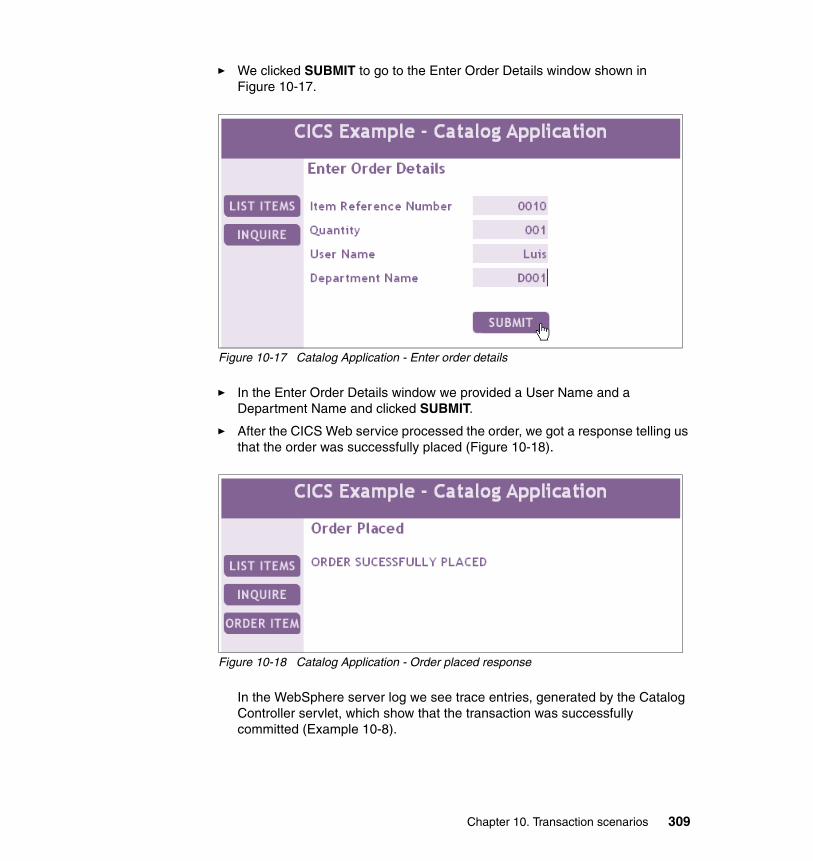
� We clicked SUBMIT to go to the Enter Order Details window shown in Figure 10-17.
Figure 10-17 Catalog Application - Enter order details
� In the Enter Order Details window we provided a User Name and a Department Name and clicked SUBMIT.
� After the CICS Web service processed the order, we got a response telling us that the order was successfully placed (Figure 10-18).
Figure 10-18 Catalog Application - Order placed response
In the WebSphere server log we see trace entries, generated by the Catalog Controller servlet, which show that the transaction was successfully committed (Example 10-8).
Chapter 10. Transaction scenarios 309
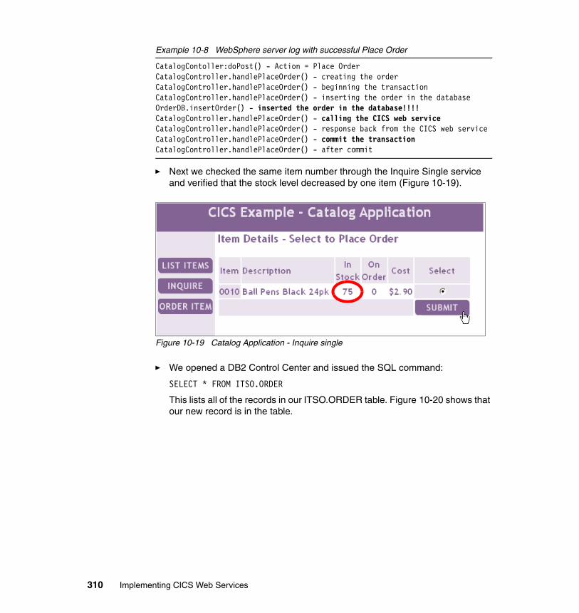
Example 10-8 WebSphere server log with successful Place Order
CatalogContoller:doPost() - Action = Place OrderCatalogController.handlePlaceOrder() - creating the orderCatalogController.handlePlaceOrder() - beginning the transactionCatalogController.handlePlaceOrder() - inserting the order in the databaseOrderDB.insertOrder() - inserted the order in the database!!!!CatalogController.handlePlaceOrder() - calling the CICS web serviceCatalogController.handlePlaceOrder() - response back from the CICS web serviceCatalogController.handlePlaceOrder() - commit the transactionCatalogController.handlePlaceOrder() - after commit
� Next we checked the same item number through the Inquire Single service and verified that the stock level decreased by one item (Figure 10-19).
Figure 10-19 Catalog Application - Inquire single
� We opened a DB2 Control Center and issued the SQL command:
SELECT * FROM ITSO.ORDER
This lists all of the records in our ITSO.ORDER table. Figure 10-20 shows that our new record is in the table.
310 Implementing CICS Web Services
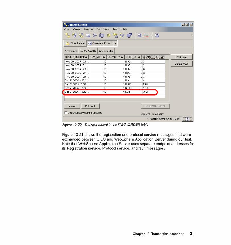
Figure 10-20 The new record in the ITSO .ORDER table
Figure 10-21 shows the registration and protocol service messages that were exchanged between CICS and WebSphere Application Server during our test. Note that WebSphere Application Server uses separate endpoint addresses for its Registration service, Protocol service, and fault messages.
Chapter 10. Transaction scenarios 311
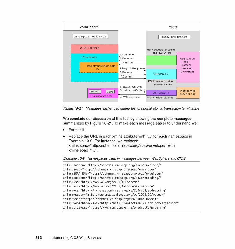
Figure 10-21 Messages exchanged during test of normal atomic transaction termination
We conclude our discussion of this test by showing the complete messages summarized by Figure 10-21. To make each message easier to understand we:
� Format it
� Replace the URL in each xmlns attribute with "..." for each namespace in Example 10-9. For instance, we replaced xmlns:soap="http://schemas.xmlsoap.org/soap/envelope/" with xmlns:soap="..." .
Example 10-9 Namespaces used in messages between WebSphere and CICS
xmlns:soapenv="http://schemas.xmlsoap.org/soap/envelope/"xmlns:soap="http://schemas.xmlsoap.org/soap/envelope/"xmlns:SOAP-ENV=”http://schemas.xmlsoap.org/soap/envelope/”xmlns:soapenc="http://schemas.xmlsoap.org/soap/encoding/"xmlns:xsd="http://www.w3.org/2001/XMLSchema"xmlns:xsi="http://www.w3.org/2001/XMLSchema-instance"xmlns:wsa="http://schemas.xmlsoap.org/ws/2004/08/addressing"xmlns:wscoor="http://schemas.xmlsoap.org/ws/2004/10/wscoor" xmlns:wsat="http://schemas.xmlsoap.org/ws/2004/10/wsat"xmlns:websphere-wsat="http://wstx.Transaction.ws.ibm.com/extension"xmlns:cicswsat="http://www.ibm.com/xmlns/prod/CICS/pipeline"
cam21-pc11.mop.ibm.com
WebSphere CICS
Web serviceprovider app
WS Provider pipeline
DFHWSATH
RS Provider pipeline (DFHWSATP)
RS Requester pipeline (DFHWSATR)
DFHWSATX
1. Invoke WS withCoordinationContext
4. WS response
2.Register
8.Committed6.Prepared
7.Commit
3.RegisterResponse5.Prepare
Registration and Protocol services(DFHPIRS)
WSATFaultPort
RegistrationCoordinator Port
mvsg3.mop.ibm.com
Coordinator
Servlet JSPs
CatalogAtomic.ear
312 Implementing CICS Web Services
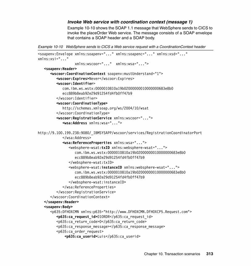
Invoke Web service with coordination context (message 1)Example 10-10 shows the SOAP 1.1 message that WebSphere sends to CICS to invoke the placeOrder Web service. The message consists of a SOAP envelope that contains a SOAP header and a SOAP body.
Example 10-10 WebSphere sends to CICS a Web service request with a CoordinationContext header
<soapenv:Envelope xmlns:soapenv="..." xmlns:soapenc="..." xmlns:xsd="..." xmlns:xsi="..." xmlns:wscoor="..." xmlns:wsa="...">
<soapenv:Header><wscoor:CoordinationContext soapenv:mustUnderstand="1">
<wscoor:Expires>Never</wscoor:Expires><wscoor:Identifier>
com.ibm.ws.wstx:0000010810a19b02000000010000000683e8b0 ecc889b8eab92e29d91254fd4fb0ff47b9 </wscoor:Identifier>
<wscoor:CoordinationType> http://schemas.xmlsoap.org/ws/2004/10/wsat </wscoor:CoordinationType>
<wscoor:RegistrationService xmlns:wscoor="..."><wsa:Address xmlns:wsa="...">
http://9.100.199.238:9080/_IBMSYSAPP/wscoor/services/RegistrationCoordinatorPort </wsa:Address>
<wsa:ReferenceProperties xmlns:wsa="..."><websphere-wsat:txID xmlns:websphere-wsat="...">
com.ibm.ws.wstx:0000010810a19b02000000010000000683e8b0 ecc889b8eab92e29d91254fd4fb0ff47b9 </websphere-wsat:txID>
<websphere-wsat:instanceID xmlns:websphere-wsat="..."> com.ibm.ws.wstx:0000010810a19b02000000010000000683e8b0 ecc889b8eab92e29d91254fd4fb0ff47b9 </websphere-wsat:instanceID>
</wsa:ReferenceProperties></wscoor:RegistrationService>
</wscoor:CoordinationContext></soapenv:Header><soapenv:Body>
<p635:DFH0XCMN xmlns:p635="http://www.DFH0XCMN.DFH0XCP5.Request.com"> <p635:ca_request_id>01ORDR</p635:ca_request_id> <p635:ca_return_code>0</p635:ca_return_code> <p635:ca_response_message></p635:ca_response_message> <p635:ca_order_request> <p635:ca_userid>Luis</p635:ca_userid>
Chapter 10. Transaction scenarios 313
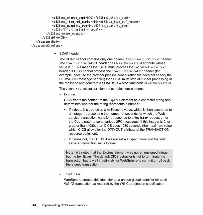
<p635:ca_charge_dept>D001</p635:ca_charge_dept> <p635:ca_item_ref_number>10</p635:ca_item_ref_number> <p635:ca_quantity_req>1</p635:ca_quantity_req> <p635:filler1 xsi:nil="true"/> </p635:ca_order_request> </p635:DFH0XCMN>
</soapenv:Body></soapenv:Envelope>
� SOAP header
The SOAP header contains only one header, a CoordinationContext header. The CoordinationContext header has a mustUnderstand attribute whose value is 1. This means that CICS must process the CoordinationContext header. If CICS cannot process the CoordinationContext header (for example, because the provider pipeline configuration file does not specify the DFHWSATH message handler) then CICS must stop all further processing of the message and generate a SOAP fault whose fault code is MustUnderstand.
The CoordinationContext element contains four elements:
– Expires
CICS treats the content of the Expires element as a character string and determines whether the string represents a number.
• If it does, it is treated as a millisecond value, which is then converted to an integer representing the number of seconds for which the Web service transaction waits for a response to a Register request or for the Coordinator to send various 2PC messages. If this integer is 0, or greater than 4080, then CICS uses 4080 seconds (the maximum value which CICS allows for the DTIMOUT attribute of the TRANSACTION resource definition).
• If it does not, then CICS does not set a suspend time and the Web service transaction waits forever.
– Identifier
WebSphere creates this identifier as a unique global identifier for each WS-AT transaction as required by the WS-Coordination specification.
Note: We noted that the Expires element was not an unsigned integer but the text Never. The default CICS behavior is not to terminate the transaction but to wait indefinitely for WebSphere to commit or roll back the atomic transaction.
314 Implementing CICS Web Services
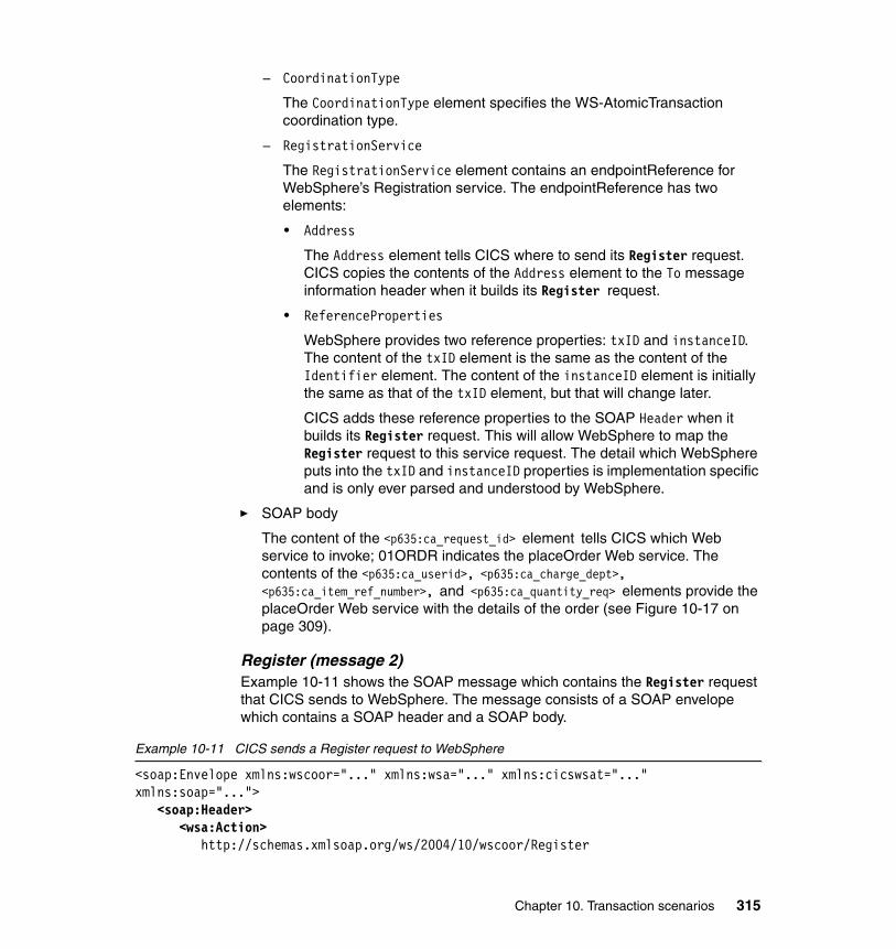
– CoordinationType
The CoordinationType element specifies the WS-AtomicTransaction coordination type.
– RegistrationService
The RegistrationService element contains an endpointReference for WebSphere’s Registration service. The endpointReference has two elements:
• Address
The Address element tells CICS where to send its Register request. CICS copies the contents of the Address element to the To message information header when it builds its Register request.
• ReferenceProperties
WebSphere provides two reference properties: txID and instanceID. The content of the txID element is the same as the content of the Identifier element. The content of the instanceID element is initially the same as that of the txID element, but that will change later.
CICS adds these reference properties to the SOAP Header when it builds its Register request. This will allow WebSphere to map the Register request to this service request. The detail which WebSphere puts into the txID and instanceID properties is implementation specific and is only ever parsed and understood by WebSphere.
� SOAP body
The content of the <p635:ca_request_id> element tells CICS which Web service to invoke; 01ORDR indicates the placeOrder Web service. The contents of the <p635:ca_userid>, <p635:ca_charge_dept>, <p635:ca_item_ref_number>, and <p635:ca_quantity_req> elements provide the placeOrder Web service with the details of the order (see Figure 10-17 on page 309).
Register (message 2)Example 10-11 shows the SOAP message which contains the Register request that CICS sends to WebSphere. The message consists of a SOAP envelope which contains a SOAP header and a SOAP body.
Example 10-11 CICS sends a Register request to WebSphere
<soap:Envelope xmlns:wscoor="..." xmlns:wsa="..." xmlns:cicswsat="..." xmlns:soap="...">
<soap:Header><wsa:Action>
http://schemas.xmlsoap.org/ws/2004/10/wscoor/Register
Chapter 10. Transaction scenarios 315
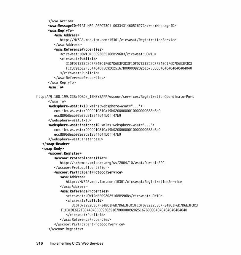
</wsa:Action><wsa:MessageID>PIAT-MSG-A6POT3C1-003343146052627C</wsa:MessageID><wsa:ReplyTo>
<wsa:Address> http://MVSG3.mop.ibm.com:15301/cicswsat/RegistrationService </wsa:Address> <wsa:ReferenceProperties> <cicswsat:UOWID>BE092025168B596B</cicswsat:UOWID> <cicswsat:PublicId> 310FD7E2E2C3C7F34BC1F6D7D6E3F3C3F10FD7E2E2C3C7F34BC1F6D7D6E3F3C3 F1C3C9E6E2F3C44040BE092025167B0000092025167B00004040404040404040 </cicswsat:PublicId> </wsa:ReferenceProperties> </wsa:ReplyTo>
<wsa:To> http://9.100.199.238:9080/_IBMSYSAPP/wscoor/services/RegistrationCoordinatorPort </wsa:To>
<websphere-wsat:txID xmlns:websphere-wsat="..."> com.ibm.ws.wstx:0000010810a19b02000000010000000683e8b0 ecc889b8eab92e29d91254fd4fb0ff47b9 </websphere-wsat:txID>
<websphere-wsat:instanceID xmlns:websphere-wsat="..."> com.ibm.ws.wstx:0000010810a19b02000000010000000683e8b0 ecc889b8eab92e29d91254fd4fb0ff47b9 </websphere-wsat:instanceID>
</soap:Header><soap:Body>
<wscoor:Register><wscoor:ProtocolIdentifier>
http://schemas.xmlsoap.org/ws/2004/10/wsat/Durable2PC </wscoor:ProtocolIdentifier>
<wscoor:ParticipantProtocolService><wsa:Address>
http://MVSG3.mop.ibm.com:15301/cicswsat/RegistrationService </wsa:Address>
<wsa:ReferenceProperties> <cicswsat:UOWID>BE092025168B596B</cicswsat:UOWID> <cicswsat:PublicId> 310FD7E2E2C3C7F34BC1F6D7D6E3F3C3F10FD7E2E2C3C7F34BC1F6D7D6E3F3C3 F1C3C9E6E2F3C44040BE092025167B0000092025167B00004040404040404040 </cicswsat:PublicId> </wsa:ReferenceProperties>
</wscoor:ParticipantProtocolService></wscoor:Register>
316 Implementing CICS Web Services
</soap:Body></soap:Envelope>
� SOAP header
The SOAP Header contains several message information headers and the two reference properties (txID and instanceID) which WebSphere sent in its Web service request. These reference properties allow WebSphere to match this Register request to its initial request for the placeOrder service. The message information headers are as follows:
– To
The To header shows that the message is being sent to the Registration Coordinator Port running in a WebSphere Application Server V6.0 region which is monitoring port 9080 on a system whose IP address is 9.100.199.238. CICS copied this from the Address element of the endpointReference for the RegistrationService in WebSphere’s service request.
– Action
The Action header indicates that CICS wishes to register with the Registration Coordinator Port.
– MessageID
The ID of the message uniquely identifies the message in space and time:
• PIAT is part of the name of module DFHPIAT; DFHPIAT generates CoordinationContext elements for CICS and interprets CoordinationContext elements received from other systems.
• A6POT3C1 is the VTAM APPLID of the CICS region which is sending the message.
• 003343146052627C is the abstime value returned by an EXEC CICS INQUIRE TIME issued in our CICS region.
– ReplyTo
The Address element of the ReplyTo header shows that the reply to this message should be sent to the Registration service running in a CICS region which is monitoring port 15301 on a z/OS system whose IP address is MVSG3.mop.ibm.com. This Registration service has two reference properties:
• UOWID
• PublicID
When WebSphere sends the RegisterResponse to CICS, it will add each of these reference properties to the response as a SOAP header. CICS
Chapter 10. Transaction scenarios 317
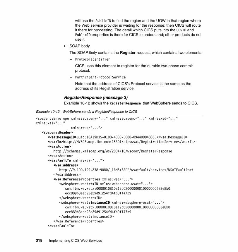
will use the PublicID to find the region and the UOW in that region where the Web service provider is waiting for the response; then CICS will route it there for processing. The detail which CICS puts into the UOWID and PublicID properties is there for CICS to understand; other products do not use it.
� SOAP body
The SOAP Body contains the Register request, which contains two elements:
– ProtocolIdentifier
CICS uses this element to register for the durable two-phase commit protocol.
– ParticipantProtocolService
Note that the address of CICS’s Protocol service is the same as the address of its Registration service.
RegisterResponse (message 3)Example 10-12 shows the RegisterResponse that WebSphere sends to CICS.
Example 10-12 WebSphere sends a RegisterResponse to CICS
<soapenv:Envelope xmlns:soapenv="..." xmlns:soapenc="..." xmlns:xsd="..." xmlns:xsi="..." xmlns:wsa="...">
<soapenv:Header><wsa:MessageID>uuid:10A19D35-0108-4000-E000-094409D4835B</wsa:MessageID><wsa:To>http://MVSG3.mop.ibm.com:15301/cicswsat/RegistrationService</wsa:To><wsa:Action>
http://schemas.xmlsoap.org/ws/2004/10/wscoor/RegisterResponse </wsa:Action>
<wsa:FaultTo xmlns:wsa="..."><wsa:Address>
http://9.100.199.238:9080/_IBMSYSAPP/wsatfault/services/WSATFaultPort </wsa:Address>
<wsa:ReferenceProperties xmlns:wsa="..."><websphere-wsat:txID xmlns:websphere-wsat="...">
com.ibm.ws.wstx:0000010810a19b02000000010000000683e8b0 ecc889b8eab92e29d91254fd4fb0ff47b9 </websphere-wsat:txID> <websphere-wsat:instanceID xmlns:websphere-wsat="..."> com.ibm.ws.wstx:0000010810a19b02000000010000000683e8b0 ecc889b8eab92e29d91254fd4fb0ff47b9 </websphere-wsat:instanceID>
</wsa:ReferenceProperties></wsa:FaultTo>
318 Implementing CICS Web Services
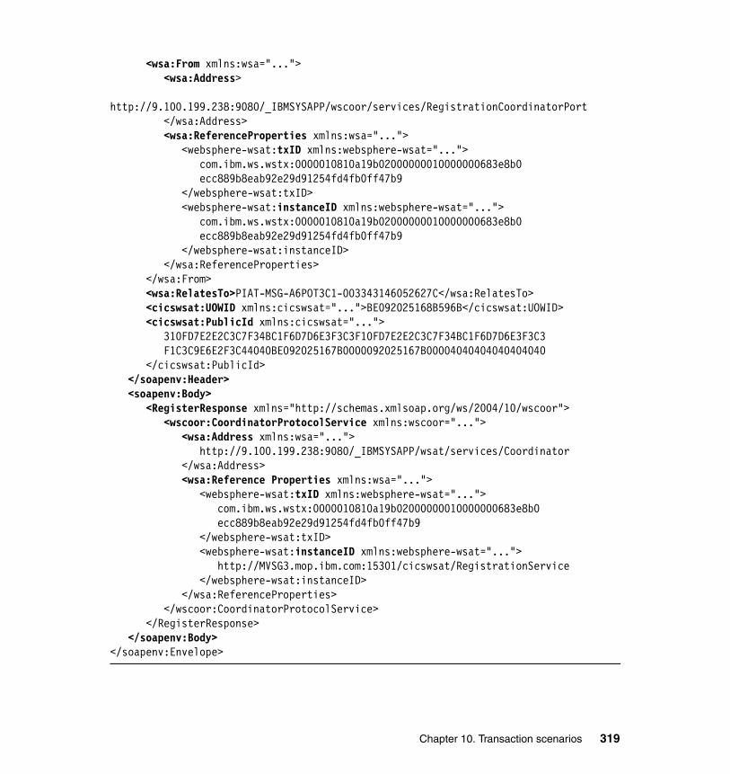
<wsa:From xmlns:wsa="..."><wsa:Address>
http://9.100.199.238:9080/_IBMSYSAPP/wscoor/services/RegistrationCoordinatorPort </wsa:Address>
<wsa:ReferenceProperties xmlns:wsa="..."><websphere-wsat:txID xmlns:websphere-wsat="...">
com.ibm.ws.wstx:0000010810a19b02000000010000000683e8b0 ecc889b8eab92e29d91254fd4fb0ff47b9 </websphere-wsat:txID> <websphere-wsat:instanceID xmlns:websphere-wsat="..."> com.ibm.ws.wstx:0000010810a19b02000000010000000683e8b0 ecc889b8eab92e29d91254fd4fb0ff47b9 </websphere-wsat:instanceID>
</wsa:ReferenceProperties></wsa:From><wsa:RelatesTo>PIAT-MSG-A6POT3C1-003343146052627C</wsa:RelatesTo><cicswsat:UOWID xmlns:cicswsat="...">BE092025168B596B</cicswsat:UOWID><cicswsat:PublicId xmlns:cicswsat="...">
310FD7E2E2C3C7F34BC1F6D7D6E3F3C3F10FD7E2E2C3C7F34BC1F6D7D6E3F3C3 F1C3C9E6E2F3C44040BE092025167B0000092025167B00004040404040404040 </cicswsat:PublicId>
</soapenv:Header><soapenv:Body>
<RegisterResponse xmlns="http://schemas.xmlsoap.org/ws/2004/10/wscoor"><wscoor:CoordinatorProtocolService xmlns:wscoor="...">
<wsa:Address xmlns:wsa="..."> http://9.100.199.238:9080/_IBMSYSAPP/wsat/services/Coordinator </wsa:Address>
<wsa:Reference Properties xmlns:wsa="..."><websphere-wsat:txID xmlns:websphere-wsat="...">
com.ibm.ws.wstx:0000010810a19b02000000010000000683e8b0 ecc889b8eab92e29d91254fd4fb0ff47b9 </websphere-wsat:txID>
<websphere-wsat:instanceID xmlns:websphere-wsat="..."> http://MVSG3.mop.ibm.com:15301/cicswsat/RegistrationService </websphere-wsat:instanceID>
</wsa:ReferenceProperties></wscoor:CoordinatorProtocolService>
</RegisterResponse></soapenv:Body>
</soapenv:Envelope>
Chapter 10. Transaction scenarios 319
� SOAP header
The SOAP Header contains several message information headers and the two reference properties (UOWID and PublicID), which CICS sent in its Register request. If we were running a CICSPlex, CICS would use these reference properties to route the response to the region and the UOW in that region where the Web service provider is waiting for it. The message information headers are as follows:
– MessageID
– To
WebSphere is sending this message to CICS’s RegistrationService. It obtained this address from the ReplyTo header in the Register request.
– Action
This message is a RegisterResponse.
– FaultTo
WebSphere wants CICS to send any SOAP faults that it has to generate to WebSphere’s WSATFaultPort.
– From
This message is coming from WebSphere’s RegistrationCoordinatorPort.
– RelatesTo
This message relates to the Register request which CICS sent.
� SOAP body
The SOAP Body contains the RegisterResponse element, which in turn contains only a CoordinatorProtocolService element. The address of WebSphere’s Protocol Service is http://9.100.199.238:9080/_IBMSYSAPP/wsat/services/CoordinatorNote that its two reference properties, txID and instanceID, no longer have the same contents; instanceID now contains the address of CICS’s Registration service.
Web service response (message 4)Since CICS has registered its interest in the atomic transaction and WebSphere has responded to that, CICS can now run the placeOrder service. When the placeOrder service has completed its work, CICS sends a response to WebSphere as shown in Example 10-13. The essence of the response is the message ORDER SUCCESSFULLY PLACED.
Example 10-13 CICS sends the Web service response to WebSphere
<SOAP-ENV:Envelope xmlns:soapenv="..." xmlns:soapenc="..." xmlns:xsd="..."
320 Implementing CICS Web Services
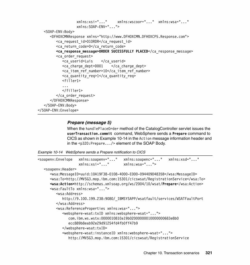
xmlns:xsi="..." xmlns:wscoor="..." xmlns:wsa="..."xmlns:SOAP-ENV="...">
<SOAP-ENV:Body><DFH0XCMNResponse xmlns="http://www.DFH0XCMN.DFH0XCP5.Response.com">
<ca_request_id>01ORDR</ca_request_id> <ca_return_code>0</ca_return_code> <ca_response_message>ORDER SUCESSFULLY PLACED</ca_response_message> <ca_order_request> <ca_userid>Luis </ca_userid> <ca_charge_dept>D001 </ca_charge_dept> <ca_item_ref_number>10</ca_item_ref_number> <ca_quantity_req>1</ca_quantity_req> <filler1>
... </filler1> </ca_order_request> </DFH0XCMNResponse>
</SOAP-ENV:Body></SOAP-ENV:Envelope>
Prepare (message 5)When the handlePlaceOrder method of the CatalogController servlet issues the userTransaction.commit command, WebSphere sends a Prepare command to CICS as shown in Example 10-14 in the Action message information header and in the <p320:Prepare.../> element of the SOAP Body.
Example 10-14 WebSphere sends a Prepare notification to CICS
<soapenv:Envelope xmlns:soapenv="..." xmlns:soapenc="..." xmlns:xsd="..." xmlns:xsi="..." xmlns:wsa="...">
<soapenv:Header><wsa:MessageID>uuid:10A19F38-0108-4000-E000-094409D4835B</wsa:MessageID><wsa:To>http://MVSG3.mop.ibm.com:15301/cicswsat/RegistrationService</wsa:To><wsa:Action>http://schemas.xmlsoap.org/ws/2004/10/wsat/Prepare</wsa:Action><wsa:FaultTo xmlns:wsa="...">
<wsa:Address> http://9.100.199.238:9080/_IBMSYSAPP/wsatfault/services/WSATFaultPort </wsa:Address>
<wsa:ReferenceProperties xmlns:wsa="..."><websphere-wsat:txID xmlns:websphere-wsat="...">
com.ibm.ws.wstx:0000010810a19b02000000010000000683e8b0 ecc889b8eab92e29d91254fd4fb0ff47b9 </websphere-wsat:txID>
<websphere-wsat:instanceID xmlns:websphere-wsat="..."> http://MVSG3.mop.ibm.com:15301/cicswsat/RegistrationService
Chapter 10. Transaction scenarios 321
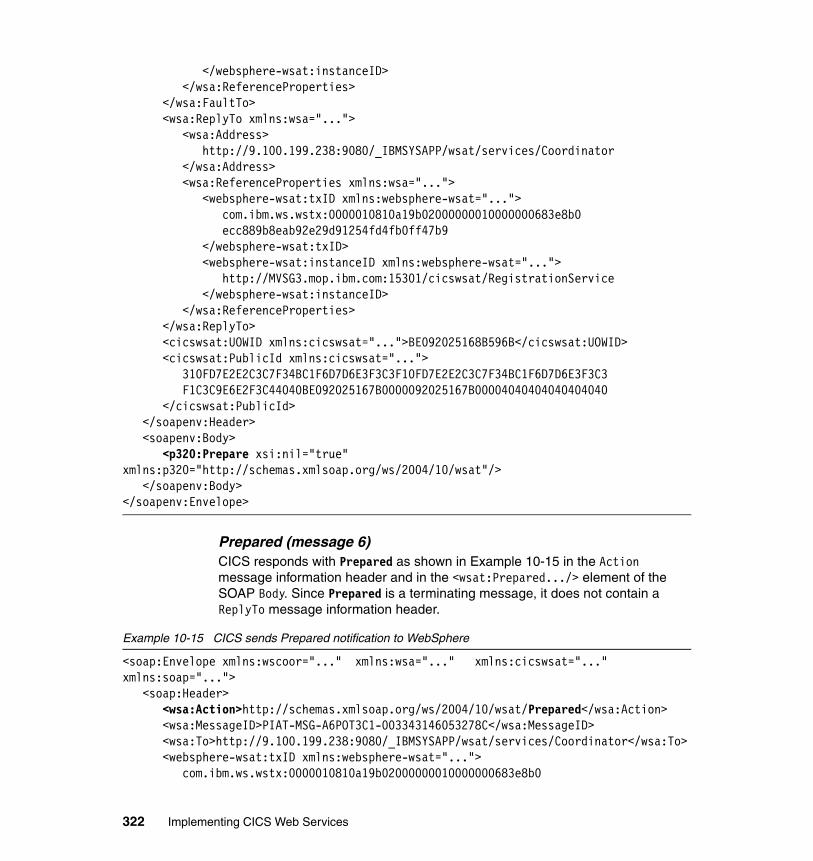
</websphere-wsat:instanceID></wsa:ReferenceProperties>
</wsa:FaultTo><wsa:ReplyTo xmlns:wsa="...">
<wsa:Address> http://9.100.199.238:9080/_IBMSYSAPP/wsat/services/Coordinator </wsa:Address>
<wsa:ReferenceProperties xmlns:wsa="..."><websphere-wsat:txID xmlns:websphere-wsat="...">
com.ibm.ws.wstx:0000010810a19b02000000010000000683e8b0 ecc889b8eab92e29d91254fd4fb0ff47b9 </websphere-wsat:txID> <websphere-wsat:instanceID xmlns:websphere-wsat="..."> http://MVSG3.mop.ibm.com:15301/cicswsat/RegistrationService </websphere-wsat:instanceID>
</wsa:ReferenceProperties></wsa:ReplyTo><cicswsat:UOWID xmlns:cicswsat="...">BE092025168B596B</cicswsat:UOWID>
<cicswsat:PublicId xmlns:cicswsat="..."> 310FD7E2E2C3C7F34BC1F6D7D6E3F3C3F10FD7E2E2C3C7F34BC1F6D7D6E3F3C3 F1C3C9E6E2F3C44040BE092025167B0000092025167B00004040404040404040 </cicswsat:PublicId>
</soapenv:Header><soapenv:Body>
<p320:Prepare xsi:nil="true" xmlns:p320="http://schemas.xmlsoap.org/ws/2004/10/wsat"/>
</soapenv:Body></soapenv:Envelope>
Prepared (message 6)CICS responds with Prepared as shown in Example 10-15 in the Action message information header and in the <wsat:Prepared.../> element of the SOAP Body. Since Prepared is a terminating message, it does not contain a ReplyTo message information header.
Example 10-15 CICS sends Prepared notification to WebSphere
<soap:Envelope xmlns:wscoor="..." xmlns:wsa="..." xmlns:cicswsat="..." xmlns:soap="...">
<soap:Header><wsa:Action>http://schemas.xmlsoap.org/ws/2004/10/wsat/Prepared</wsa:Action><wsa:MessageID>PIAT-MSG-A6POT3C1-003343146053278C</wsa:MessageID><wsa:To>http://9.100.199.238:9080/_IBMSYSAPP/wsat/services/Coordinator</wsa:To><websphere-wsat:txID xmlns:websphere-wsat="...">
com.ibm.ws.wstx:0000010810a19b02000000010000000683e8b0
322 Implementing CICS Web Services
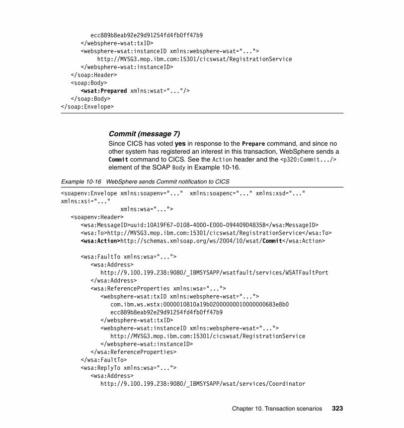
ecc889b8eab92e29d91254fd4fb0ff47b9 </websphere-wsat:txID>
<websphere-wsat:instanceID xmlns:websphere-wsat="..."> http://MVSG3.mop.ibm.com:15301/cicswsat/RegistrationService </websphere-wsat:instanceID>
</soap:Header><soap:Body>
<wsat:Prepared xmlns:wsat="..."/></soap:Body>
</soap:Envelope>
Commit (message 7)Since CICS has voted yes in response to the Prepare command, and since no other system has registered an interest in this transaction, WebSphere sends a Commit command to CICS. See the Action header and the <p320:Commit.../> element of the SOAP Body in Example 10-16.
Example 10-16 WebSphere sends Commit notification to CICS
<soapenv:Envelope xmlns:soapenv="..." xmlns:soapenc="..." xmlns:xsd="..." xmlns:xsi="..." xmlns:wsa="...">
<soapenv:Header><wsa:MessageID>uuid:10A19F67-0108-4000-E000-094409D4835B</wsa:MessageID><wsa:To>http://MVSG3.mop.ibm.com:15301/cicswsat/RegistrationService</wsa:To><wsa:Action>http://schemas.xmlsoap.org/ws/2004/10/wsat/Commit</wsa:Action>
<wsa:FaultTo xmlns:wsa="...">
<wsa:Address> http://9.100.199.238:9080/_IBMSYSAPP/wsatfault/services/WSATFaultPort </wsa:Address>
<wsa:ReferenceProperties xmlns:wsa="..."><websphere-wsat:txID xmlns:websphere-wsat="...">
com.ibm.ws.wstx:0000010810a19b02000000010000000683e8b0 ecc889b8eab92e29d91254fd4fb0ff47b9 </websphere-wsat:txID>
<websphere-wsat:instanceID xmlns:websphere-wsat="..."> http://MVSG3.mop.ibm.com:15301/cicswsat/RegistrationService </websphere-wsat:instanceID>
</wsa:ReferenceProperties></wsa:FaultTo><wsa:ReplyTo xmlns:wsa="...">
<wsa:Address> http://9.100.199.238:9080/_IBMSYSAPP/wsat/services/Coordinator
Chapter 10. Transaction scenarios 323
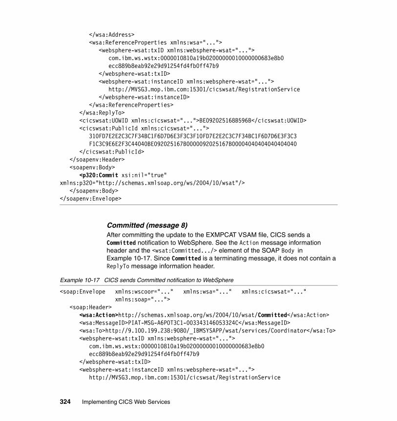
</wsa:Address><wsa:ReferenceProperties xmlns:wsa="...">
<websphere-wsat:txID xmlns:websphere-wsat="..."> com.ibm.ws.wstx:0000010810a19b02000000010000000683e8b0 ecc889b8eab92e29d91254fd4fb0ff47b9 </websphere-wsat:txID> <websphere-wsat:instanceID xmlns:websphere-wsat="..."> http://MVSG3.mop.ibm.com:15301/cicswsat/RegistrationService </websphere-wsat:instanceID>
</wsa:ReferenceProperties></wsa:ReplyTo><cicswsat:UOWID xmlns:cicswsat="...">BE092025168B596B</cicswsat:UOWID><cicswsat:PublicId xmlns:cicswsat="...">
310FD7E2E2C3C7F34BC1F6D7D6E3F3C3F10FD7E2E2C3C7F34BC1F6D7D6E3F3C3 F1C3C9E6E2F3C44040BE092025167B0000092025167B00004040404040404040 </cicswsat:PublicId>
</soapenv:Header><soapenv:Body>
<p320:Commit xsi:nil="true" xmlns:p320="http://schemas.xmlsoap.org/ws/2004/10/wsat"/>
</soapenv:Body></soapenv:Envelope>
Committed (message 8)After committing the update to the EXMPCAT VSAM file, CICS sends a Committed notification to WebSphere. See the Action message information header and the <wsat:Committed.../> element of the SOAP Body in Example 10-17. Since Committed is a terminating message, it does not contain a ReplyTo message information header.
Example 10-17 CICS sends Committed notification to WebSphere
<soap:Envelope xmlns:wscoor="..." xmlns:wsa="..." xmlns:cicswsat="..." xmlns:soap="...">
<soap:Header><wsa:Action>http://schemas.xmlsoap.org/ws/2004/10/wsat/Committed</wsa:Action><wsa:MessageID>PIAT-MSG-A6POT3C1-003343146053324C</wsa:MessageID><wsa:To>http://9.100.199.238:9080/_IBMSYSAPP/wsat/services/Coordinator</wsa:To><websphere-wsat:txID xmlns:websphere-wsat="...">
com.ibm.ws.wstx:0000010810a19b02000000010000000683e8b0 ecc889b8eab92e29d91254fd4fb0ff47b9 </websphere-wsat:txID>
<websphere-wsat:instanceID xmlns:websphere-wsat="..."> http://MVSG3.mop.ibm.com:15301/cicswsat/RegistrationService
324 Implementing CICS Web Services
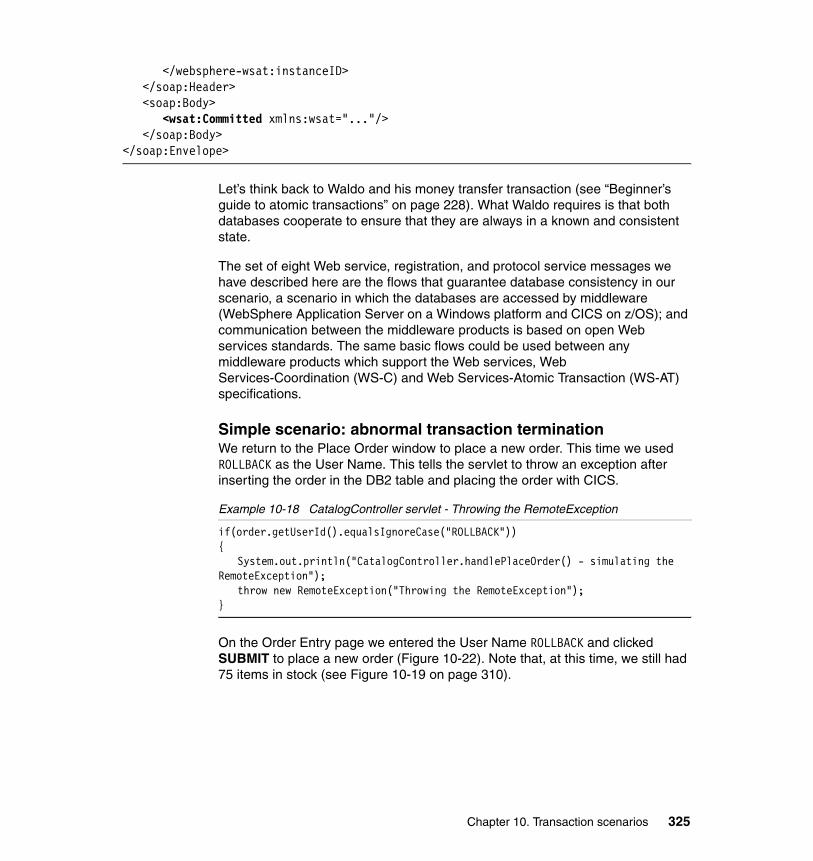
</websphere-wsat:instanceID></soap:Header><soap:Body>
<wsat:Committed xmlns:wsat="..."/></soap:Body>
</soap:Envelope>
Let’s think back to Waldo and his money transfer transaction (see “Beginner’s guide to atomic transactions” on page 228). What Waldo requires is that both databases cooperate to ensure that they are always in a known and consistent state.
The set of eight Web service, registration, and protocol service messages we have described here are the flows that guarantee database consistency in our scenario, a scenario in which the databases are accessed by middleware (WebSphere Application Server on a Windows platform and CICS on z/OS); and communication between the middleware products is based on open Web services standards. The same basic flows could be used between any middleware products which support the Web services, Web Services-Coordination (WS-C) and Web Services-Atomic Transaction (WS-AT) specifications.
Simple scenario: abnormal transaction terminationWe return to the Place Order window to place a new order. This time we used ROLLBACK as the User Name. This tells the servlet to throw an exception after inserting the order in the DB2 table and placing the order with CICS.
Example 10-18 CatalogController servlet - Throwing the RemoteException
if(order.getUserId().equalsIgnoreCase("ROLLBACK")){
System.out.println("CatalogController.handlePlaceOrder() - simulating the RemoteException");
throw new RemoteException("Throwing the RemoteException");}
On the Order Entry page we entered the User Name ROLLBACK and clicked SUBMIT to place a new order (Figure 10-22). Note that, at this time, we still had 75 items in stock (see Figure 10-19 on page 310).
Chapter 10. Transaction scenarios 325
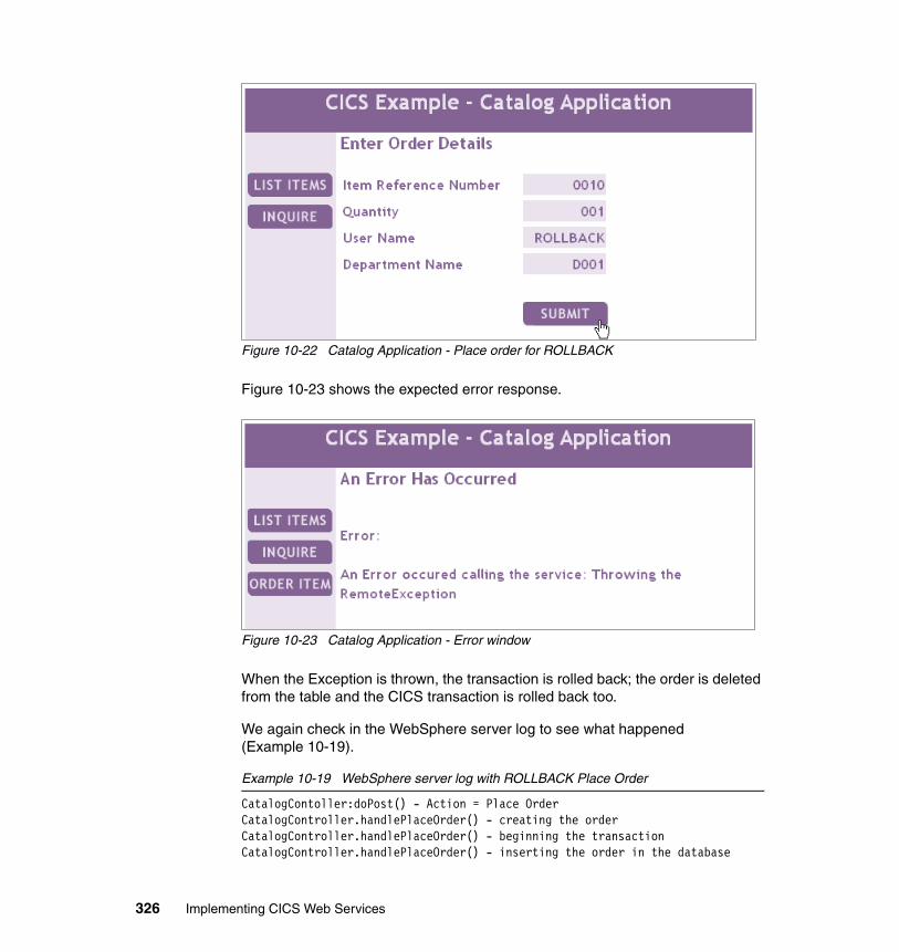
Figure 10-22 Catalog Application - Place order for ROLLBACK
Figure 10-23 shows the expected error response.
Figure 10-23 Catalog Application - Error window
When the Exception is thrown, the transaction is rolled back; the order is deleted from the table and the CICS transaction is rolled back too.
We again check in the WebSphere server log to see what happened (Example 10-19).
Example 10-19 WebSphere server log with ROLLBACK Place Order
CatalogContoller:doPost() - Action = Place OrderCatalogController.handlePlaceOrder() - creating the orderCatalogController.handlePlaceOrder() - beginning the transactionCatalogController.handlePlaceOrder() - inserting the order in the database
326 Implementing CICS Web Services
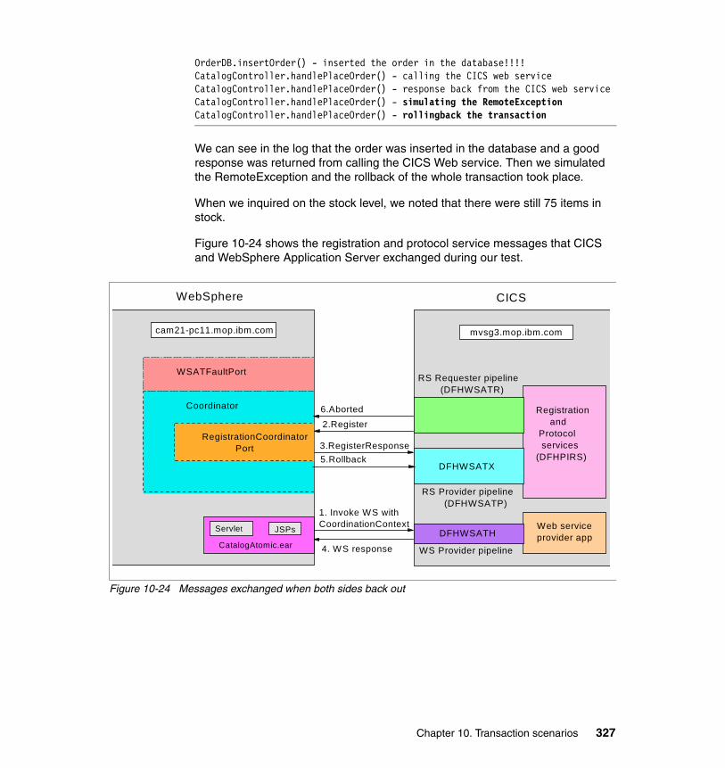
OrderDB.insertOrder() - inserted the order in the database!!!!CatalogController.handlePlaceOrder() - calling the CICS web serviceCatalogController.handlePlaceOrder() - response back from the CICS web serviceCatalogController.handlePlaceOrder() - simulating the RemoteExceptionCatalogController.handlePlaceOrder() - rollingback the transaction
We can see in the log that the order was inserted in the database and a good response was returned from calling the CICS Web service. Then we simulated the RemoteException and the rollback of the whole transaction took place.
When we inquired on the stock level, we noted that there were still 75 items in stock.
Figure 10-24 shows the registration and protocol service messages that CICS and WebSphere Application Server exchanged during our test.
Figure 10-24 Messages exchanged when both sides back out
cam21-pc11.mop.ibm.com
WebSphere
Web serviceprovider app
WS Provider pipeline
DFHWSATH
RS Provider pipeline (DFHWSATP)
RS Requester pipeline (DFHWSATR)
DFHWSATX
1. Invoke WS withCoordinationContext
4. WS response
2.Register6.Aborted
3.RegisterResponse5.Rollback
Registration and Protocol services(DFHPIRS)
WSATFaultPort
RegistrationCoordinator Port
mvsg3.mop.ibm.com
Coordinator
Servlet JSPs
CatalogAtomic.ear
CICS
Chapter 10. Transaction scenarios 327
10.3 The daisy chain atomic transaction scenario
We now extend the simple atomic transaction scenario to a daisy chain scenario by making the following modifications:
� Changing the configuration of the CICS sample Catalog application such that it makes an outbound Web service call
� Changing the ExampleAppDispatchOrder.ear file provided with CICS TS V3.1
ExampleAppDispatchOrder.ear is an enterprise archive provided with the Catalog application that can be deployed in WebSphere Application Server and used as an order dispatch endpoint. See “Catalog manager example application” on page 67 for more information on the sample application.
We modified the ExampleAppDispatchOrder.ear file to insert records into a DB2 table called ITSO.DISPATCH. The ITSO.DISPATCH table logs all of the orders dispatched through the dispatchOrder Web service. We called the modified program DispatchOrderAtomic.ear.
By making these changes, we have a global transaction that updates three resources:
� A DB2 table in the Windows environment� A VSAM file in the z/OS environment� Another DB2 table in a Windows environment
We have a daisy chain from WebSphere to CICS to WebSphere. CICS acts as both a coordinator and a participant.
Figure 10-25 shows the sequence of events for the whole transaction.
328 Implementing CICS Web Services
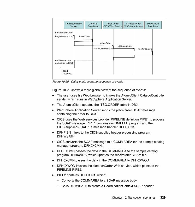
Figure 10-25 Daisy chain scenario sequence of events
Figure 10-26 shows a more global view of the sequence of events:
� The user uses his Web browser to invoke the AtomicClient CatalogController servlet, which runs in WebSphere Application Server.
� The AtomicClient updates the ITSO.ORDER table in DB2.
� WebSphere Application Server sends the placeOrder SOAP message containing the order to CICS.
� CICS uses the Web services provider PIPELINE definition PIPE1 to process the SOAP message. PIPE1 contains our SNIFFER program and the CICS-supplied SOAP 1.1 message handler DFHPISN1.
� DFHPISN1 links to the CICS-supplied header processing program DFHWSATH.
� CICS converts the SOAP message to a COMMAREA for the sample catalog manager program, DFH0XCMN.
� DFH0XCMN passes the data in the COMMAREA to the sample catalog program DFH0XVDS, which updates the recoverable VSAM file.
� DFH0XCMN passes the data in the COMMAREA to DFH0XWOD.
� DFH0XWOD invokes the dispatchOrder Web service, which points to the PIPELINE PIPE2.
� PIPE2 contains DFHPISN1, which:
– Converts the COMMAREA to a SOAP message body
– Calls DFHWSATH to create a CoordinationContext SOAP header
CatalogControllerServlet
OrderDBJava Bean
Place OrderCICS Web Service
handlePlaceOrder
insertOrder
dispatchOrderDFH0XCMNOperation
beginTransaction
endTransactioncommit or rollback
sendresponse
DispatchOrderWAS Web Service
DispatchDBJava Bean
placeOrder
insertDispatch
Chapter 10. Transaction scenarios 329
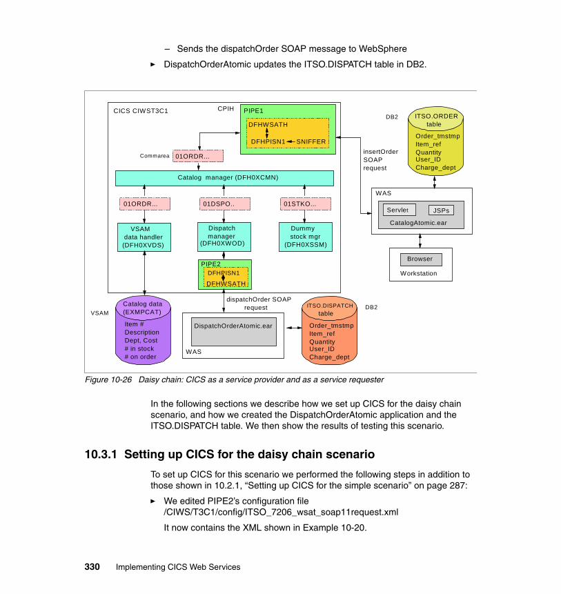
– Sends the dispatchOrder SOAP message to WebSphere
� DispatchOrderAtomic updates the ITSO.DISPATCH table in DB2.
Figure 10-26 Daisy chain: CICS as a service provider and as a service requester
In the following sections we describe how we set up CICS for the daisy chain scenario, and how we created the DispatchOrderAtomic application and the ITSO.DISPATCH table. We then show the results of testing this scenario.
10.3.1 Setting up CICS for the daisy chain scenario
To set up CICS for this scenario we performed the following steps in addition to those shown in 10.2.1, “Setting up CICS for the simple scenario” on page 287:
� We edited PIPE2’s configuration file /CIWS/T3C1/config/ITSO_7206_wsat_soap11request.xml
It now contains the XML shown in Example 10-20.
CICS CIWST3C1DB2 ITSO.ORDER
table
Order_tmstmpItem_refQuantity User_IDCharge_dept
insertOrder SOAPrequest
Workstation
Browser
Servlet JSPs
CatalogAtomic.ear
WAS
Catalog manager (DFH0XCMN)
Dummy stock mgr (DFH0XSSM)
VSAM data handler(DFH0XVDS)
Dispatch manager (DFH0XWOD)
01ORDR... 01DSPO.. 01STKO...
DFHWSATH
CPIH
DFHPISN1 SNIFFER
PIPE1
01ORDR...Commarea
Catalog data(EXMPCAT)
Item #DescriptionDept, Cost# in stock# on order
DispatchOrderAtomic.ear
WAS
DB2ITSO.DISPATCH table
Order_tmstmpItem_refQuantity User_IDCharge_dept
VSAM
DFHWSATH
PIPE2DFHPISN1
dispatchOrder SOAP request
330 Implementing CICS Web Services
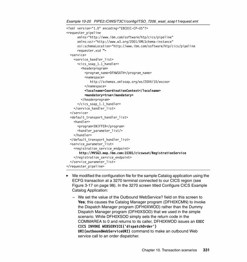
Example 10-20 PIPE2:/CIWS/T3C1/config/ITSO_7206_wsat_soap11request.xml
<?xml version="1.0" encoding="EBCDIC-CP-US"?> <requester_pipeline
xmlns="http://www.ibm.com/software/htp/cics/pipeline" xmlns:xsi="http://www.w3.org/2001/XMLSchema-instance" xsi:schemaLocation="http://www.ibm.com/software/htp/cics/pipelinerequester.xsd “>
<service> <service_handler_list> <cics_soap_1.1_handler> <headerprogram> <program_name>DFHWSATH</program_name> <namespace> http://schemas.xmlsoap.org/ws/2004/10/wscoor </namespace> <localname>CoordinationContext</localname> <mandatory>true</mandatory> </headerprogram> </cics_soap_1.1_handler> </service_handler_list> </service> <default_transport_handler_list> <handler> <program>SNIFFER</program>
<handler_parameter_list/> </handler> </default_transport_handler_list> <service_parameter_list> <registration_service_endpoint>
http://MVSG3.mop.ibm.com:15301/cicswsat/RegistrationService</registration_service_endpoint>
</service_parameter_list> </requester_pipeline>
� We modified the configuration file for the sample Catalog application using the ECFG transaction at a 3270 terminal connected to our CICS region (see Figure 3-17 on page 98). In the 3270 screen titled Configure CICS Example Catalog Application:
– We set the value of the Outbound WebService? field on this screen to Yes; this causes the Catalog Manager program (DFH0XCMN) to invoke the Dispatch Manager program (DFH0XWOD) rather than the Dummy Dispatch Manager program (DFH0XSOD) that we used in the simple scenario. While DFH0XSOD simply sets the return code in the COMMAREA to 0 and returns to its caller, DFH0XWOD issues an EXEC CICS INVOKE WEBSERVICE('dispatchOrder') URI(outboundWebServiceURI) command to make an outbound Web service call to an order dispatcher.
Chapter 10. Transaction scenarios 331
– We set the value of the Outbound WebService URI field to the location of the Web service that implements the order dispatcher function. We ran the dispatchOrder service on WebSphere Application Server for Windows.
10.3.2 Creating DispatchOrderAtomic and the ITSO.DISPATCH table
To create the DispatchOrderAtomic application and the ITSO.DISPATCH table, we did the following:
� Created the DispatchDB JavaBean that inserts the dispatch order into the DB2 table.
� Changed the dispatchOrder method in the DispatchOrderSoapBindingImpl class in order to call the DispatchDB JavaBean. DispatchOrderSoapBindingImpl is the bean that serves the Web service and dispatchOrder is the method that is called when the Web service is requested.
� Changed the deployment descriptor of the DispatchOrderAtomic application so that it is executed as part of a Web Services Atomic Transaction.
� Created the ITSO.DISPATCH table.
We explain each step in detail in the following sections.
Create the DispatchDB JavaBeanIn the same way that we previously created the OrderDB JavaBean, we created the DispatchDB JavaBean. This bean has a method that inserts the dispatch order into the ITSO.DISPATCH table. The input parameter is an OrderBean that has all the data needed for the insert. We do not show the DispatchDB JavaBean code here because it is very similar to the OrderDB code shown in Example 10-4 on page 292.
Change the dispatchOrder methodWhen the dispatchOrder Web service is called, the dispatchOrder method in the DispatchOrderSoapBindingImpl Java class is called. It is responsible to perform the service and send a response. We changed this method to create an OrderBean and to perform the insert by calling the insertDispatch method in the DispatchDB JavaBean.
The dispatchOrder method is shown in Example 10-21.
Example 10-21 The dispatchOrder method
public com.Response.dispatchOrder.exampleApp.www.DispatchOrderResponse dispatchOrder(com.Request.dispatchOrder.exampleApp.www.DispatchOrderRequest
requestPart) throws java.rmi.RemoteException {
332 Implementing CICS Web Services
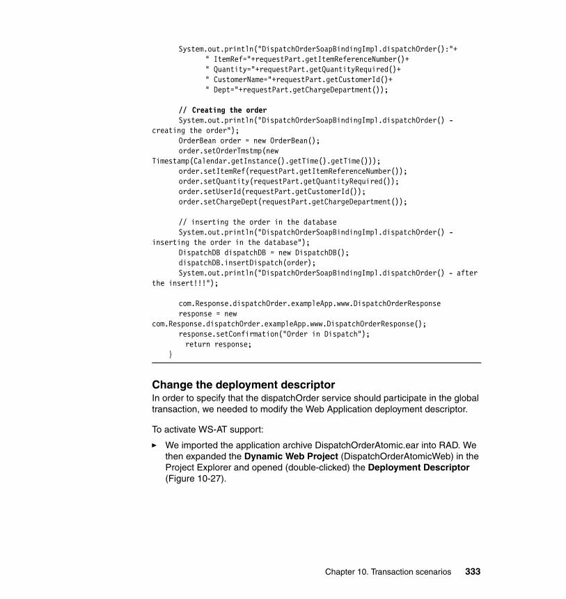
System.out.println("DispatchOrderSoapBindingImpl.dispatchOrder():"+" ItemRef="+requestPart.getItemReferenceNumber()+" Quantity="+requestPart.getQuantityRequired()+" CustomerName="+requestPart.getCustomerId()+" Dept="+requestPart.getChargeDepartment());
// Creating the orderSystem.out.println("DispatchOrderSoapBindingImpl.dispatchOrder() -
creating the order");OrderBean order = new OrderBean();order.setOrderTmstmp(new
Timestamp(Calendar.getInstance().getTime().getTime()));order.setItemRef(requestPart.getItemReferenceNumber());order.setQuantity(requestPart.getQuantityRequired());order.setUserId(requestPart.getCustomerId());order.setChargeDept(requestPart.getChargeDepartment());
// inserting the order in the databaseSystem.out.println("DispatchOrderSoapBindingImpl.dispatchOrder() -
inserting the order in the database");DispatchDB dispatchDB = new DispatchDB();dispatchDB.insertDispatch(order);System.out.println("DispatchOrderSoapBindingImpl.dispatchOrder() - after
the insert!!!");
com.Response.dispatchOrder.exampleApp.www.DispatchOrderResponse response = new
com.Response.dispatchOrder.exampleApp.www.DispatchOrderResponse();response.setConfirmation("Order in Dispatch");
return response; }
Change the deployment descriptorIn order to specify that the dispatchOrder service should participate in the global transaction, we needed to modify the Web Application deployment descriptor.
To activate WS-AT support:
� We imported the application archive DispatchOrderAtomic.ear into RAD. We then expanded the Dynamic Web Project (DispatchOrderAtomicWeb) in the Project Explorer and opened (double-clicked) the Deployment Descriptor (Figure 10-27).
Chapter 10. Transaction scenarios 333
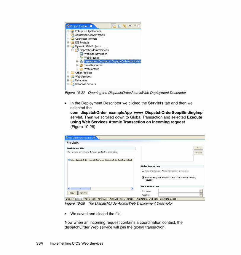
Figure 10-27 Opening the DispatchOrderAtomicWeb Deployment Descriptor
� In the Deployment Descriptor we clicked the Servlets tab and then we selected the com_dispatchOrder_exampleApp_www_DispatchOrderSoapBindingImpl servlet. Then we scrolled down to Global Transaction and selected Execute using Web Services Atomic Transaction on incoming request (Figure 10-28).
Figure 10-28 The DispatchOrderAtomicWeb Deployment Descriptor
� We saved and closed the file.
Now when an incoming request contains a coordination context, the dispatchOrder Web service will join the global transaction.
334 Implementing CICS Web Services
Create the ITSO.DISPATCH tableWe created the ITSO.DISPATCH table to record all the dispatch orders that come to the dispatchOrder Web service. Example 10-22 shows the script we used to create the table.
Example 10-22 Creation of ITSO.DISPATCH table
-- IBM ITSO
CONNECT RESET;
CONNECT TO ITSOWS;
-- Table definitions for DispatchCREATE TABLE ITSO.DISPATCH (DISPATCH_TMSTMP TIMESTAMP NOT NULL , ITEM_REF INTEGER NOT NULL , QUANTITY INTEGER NOT NULL , USER_ID CHARACTER (20) NOT NULL , CHARGE_DEPT CHARACTER (20) NOT NULL , CONSTRAINT DISPATCHKEY PRIMARY KEY (DISPATCH_TMSTMP) ) ;
The ITSO.DISPATCH table has a column for every field in the Catalog Place Order JSP. Also, there is a TimeStamp column that is used as a unique key for the table.
10.3.3 Testing the daisy chain scenario
We performed two tests of the daisy chain scenario:
� Normal transaction termination� Abnormal transaction termination (see “Daisy chain scenario: abnormal
transaction termination” on page 341)
Daisy chain scenario: normal transaction terminationIn this section, we explain how we ran the AtomicClient application and then show the registration and protocol service messages that are exchanged between WebSphere Application Server and CICS during the normal termination of the atomic transaction.
To run the scenario we did the following:
� Opened the welcome page of the Catalog application.
http://cam21-pc11:9080/CatalogAtomicWeb/Welcome.jsp
� Clicked INQUIRE to perform an inquireSingle operation.
Chapter 10. Transaction scenarios 335
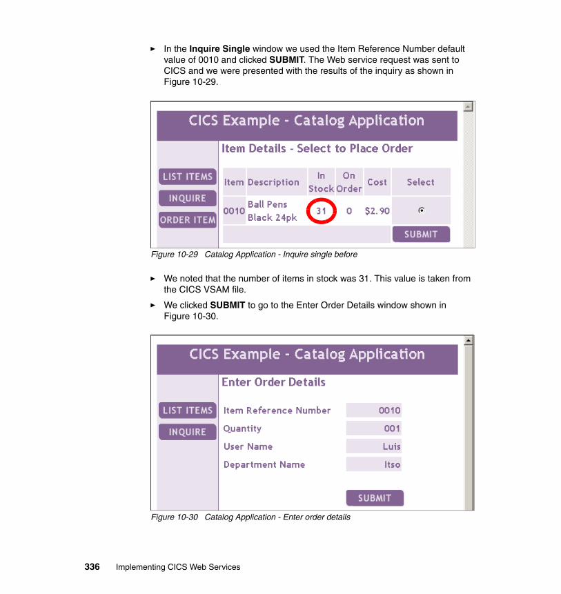
� In the Inquire Single window we used the Item Reference Number default value of 0010 and clicked SUBMIT. The Web service request was sent to CICS and we were presented with the results of the inquiry as shown in Figure 10-29.
Figure 10-29 Catalog Application - Inquire single before
� We noted that the number of items in stock was 31. This value is taken from the CICS VSAM file.
� We clicked SUBMIT to go to the Enter Order Details window shown in Figure 10-30.
Figure 10-30 Catalog Application - Enter order details
336 Implementing CICS Web Services
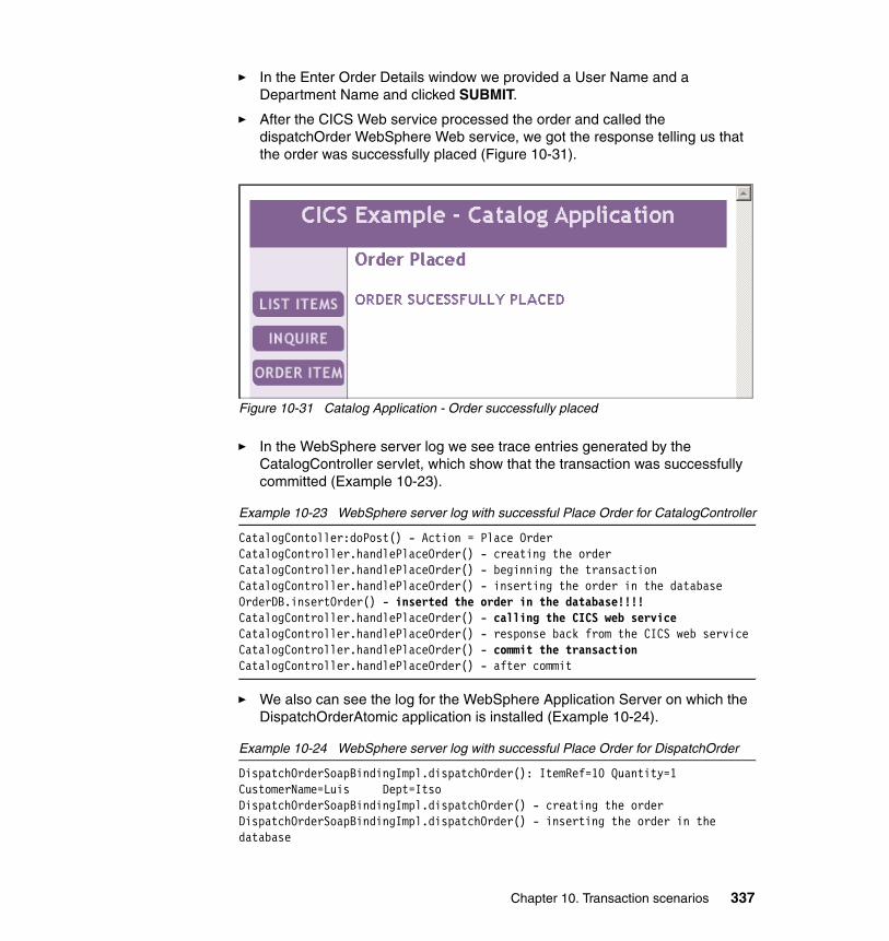
� In the Enter Order Details window we provided a User Name and a Department Name and clicked SUBMIT.
� After the CICS Web service processed the order and called the dispatchOrder WebSphere Web service, we got the response telling us that the order was successfully placed (Figure 10-31).
Figure 10-31 Catalog Application - Order successfully placed
� In the WebSphere server log we see trace entries generated by the CatalogController servlet, which show that the transaction was successfully committed (Example 10-23).
Example 10-23 WebSphere server log with successful Place Order for CatalogController
CatalogContoller:doPost() - Action = Place OrderCatalogController.handlePlaceOrder() - creating the orderCatalogController.handlePlaceOrder() - beginning the transactionCatalogController.handlePlaceOrder() - inserting the order in the databaseOrderDB.insertOrder() - inserted the order in the database!!!!CatalogController.handlePlaceOrder() - calling the CICS web serviceCatalogController.handlePlaceOrder() - response back from the CICS web serviceCatalogController.handlePlaceOrder() - commit the transactionCatalogController.handlePlaceOrder() - after commit
� We also can see the log for the WebSphere Application Server on which the DispatchOrderAtomic application is installed (Example 10-24).
Example 10-24 WebSphere server log with successful Place Order for DispatchOrder
DispatchOrderSoapBindingImpl.dispatchOrder(): ItemRef=10 Quantity=1 CustomerName=Luis Dept=Itso DispatchOrderSoapBindingImpl.dispatchOrder() - creating the orderDispatchOrderSoapBindingImpl.dispatchOrder() - inserting the order in the database
Chapter 10. Transaction scenarios 337
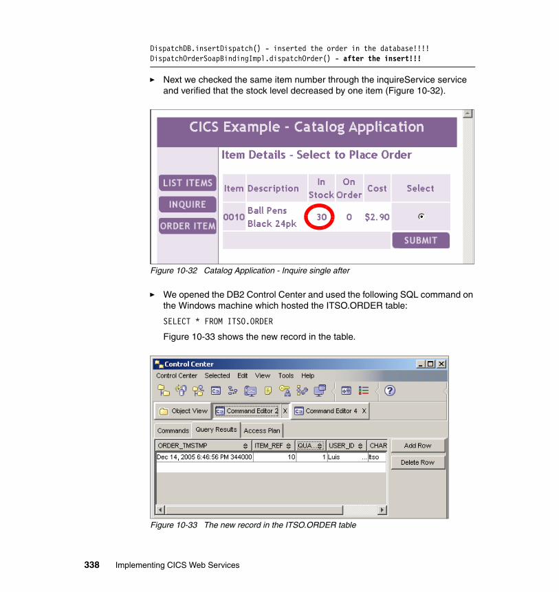
DispatchDB.insertDispatch() - inserted the order in the database!!!!DispatchOrderSoapBindingImpl.dispatchOrder() - after the insert!!!
� Next we checked the same item number through the inquireService service and verified that the stock level decreased by one item (Figure 10-32).
Figure 10-32 Catalog Application - Inquire single after
� We opened the DB2 Control Center and used the following SQL command on the Windows machine which hosted the ITSO.ORDER table:
SELECT * FROM ITSO.ORDER
Figure 10-33 shows the new record in the table.
Figure 10-33 The new record in the ITSO.ORDER table
338 Implementing CICS Web Services
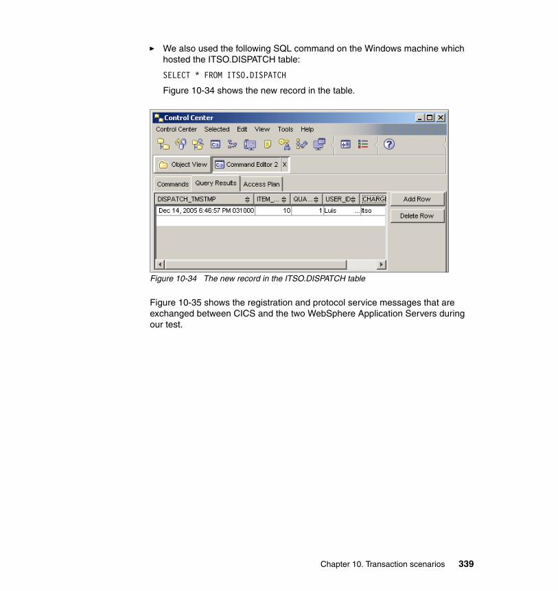
� We also used the following SQL command on the Windows machine which hosted the ITSO.DISPATCH table:
SELECT * FROM ITSO.DISPATCH
Figure 10-34 shows the new record in the table.
Figure 10-34 The new record in the ITSO.DISPATCH table
Figure 10-35 shows the registration and protocol service messages that are exchanged between CICS and the two WebSphere Application Servers during our test.
Chapter 10. Transaction scenarios 339
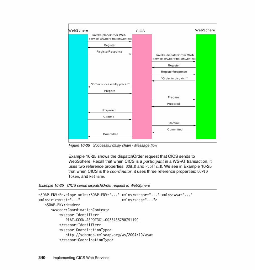
Figure 10-35 Successful daisy chain - Message flow
Example 10-25 shows the dispatchOrder request that CICS sends to WebSphere. Recall that when CICS is a participant in a WS-AT transaction, it uses two reference properties: UOWID and PublicID. We see in Example 10-25 that when CICS is the coordinator, it uses three reference properties: UOWID, Token, and Netname.
Example 10-25 CICS sends dispatchOrder request to WebSphere
<SOAP-ENV:Envelope xmlns:SOAP-ENV="..." xmlns:wscoor="..." xmlns:wsa="..." xmlns:cicswsat="..." xmlns:soap="..."> <SOAP-ENV:Header> <wscoor:CoordinationContext> <wscoor:Identifier> PIAT-CCON-A6POT3C1-003343578075119C </wscoor:Identifier> <wscoor:CoordinationType> http://schemas.xmlsoap.org/ws/2004/10/wsat </wscoor:CoordinationType>
WebSphere CICSWebSphere
Invoke dispatchOrder Webservice w/CoordinationContext
Register
RegisterResponse
Invoke placeOrder Webservice w/CoordinationContext
Register
RegisterResponse
"Order in dispatch"
Prepare
Prepared
Prepared
Commit
Commit
Prepare
"Order successfully placed"
Committed Committed
340 Implementing CICS Web Services
<wscoor:RegistrationService> <wsa:Address> http://MVSG3.mop.ibm.com:15301/cicswsat/RegistrationService </wsa:Address> <wsa:ReferenceProperties> <cicswsat:Netname>A6POT3C1</cicswsat:Netname> <cicswsat:Token>F0F0F0F0</cicswsat:Token> <cicswsat:UOWID>BE0F698D97751D67</cicswsat:UOWID> </wsa:ReferenceProperties> </wscoor:RegistrationService> </wscoor:CoordinationContext> </SOAP-ENV:Header> <SOAP-ENV:Body> <dispatchOrderRequest xmlns="http://www.exampleApp.dispatchOrder.Request.com"> <itemReferenceNumber>10</itemReferenceNumber> <quantityRequired>1</quantityRequired> <customerId>Luis </customerId> <chargeDepartment>Itso </chargeDepartment> </dispatchOrderRequest> </SOAP-ENV:Body></SOAP-ENV:Envelope>
Daisy chain scenario: abnormal transaction terminationFinally, we tested the daisy chain scenario, but this time with a RemoteException thrown at the end of the execution. We returned to the Place Order window to place a new order. This time we used ROLLBACK as the User Name (see Figure 10-22 on page 326). In the daisy chain scenario, this exception takes place after the insertions in the two DB2 tables and the update of the CICS VSAM file.
When the exception is thrown, the transaction is rolled back and the updates are backed out from:
� The ITSO.ORDER table
� The CICS VSAM file
� The ITSO.DISPATCH table
We can see in the WebSphere logs that the AtomicClient application successfully inserted the order record in the database prior to rolling back the transaction (Example 10-26).
Example 10-26 Catalog Application log
CatalogContoller:doPost() - Action = Place OrderCatalogController.handlePlaceOrder() - creating the order
Chapter 10. Transaction scenarios 341
CatalogController.handlePlaceOrder() - beginning the transactionCatalogController.handlePlaceOrder() - inserting the order in the databaseOrderDB.insertOrder() - inserted the order in the database!!!!CatalogController.handlePlaceOrder() - calling the CICS web serviceCatalogController.handlePlaceOrder() - response back from the CICS web serviceCatalogController.handlePlaceOrder() - simulating the RemoteExceptionCatalogController.handlePlaceOrder() - rollingback the transaction
We also can see that the DispatchOrderAtomic application successfully inserted the order record (Example 10-27).
Example 10-27 DispatchOrder Application log
DispatchOrderSoapBindingImpl.dispatchOrder(): ItemRef=10 Quantity=1 CustomerName=ROLLBACK Dept=Itso DispatchOrderSoapBindingImpl.dispatchOrder() - creating the orderDispatchOrderSoapBindingImpl.dispatchOrder() - inserting the order in the databaseDispatchDB.insertDispatch() - inserted the order in the database!!!!DispatchOrderSoapBindingImpl.dispatchOrder() - after the insert!!!
Following the RemoteException, the atomic transaction is rolled back. When we inquired on the stock level, we noted that there were still 30 items in stock.
10.4 Transaction scenario summary
These test scenarios demonstrate how you can synchronize WebSphere and CICS updates using WS-AT. They show how the classical 2PC distributed transaction can be implemented using Web services, and that the distributed global transaction can be committed or rolled back based on a set of Web service flows that are managed entirely by the WebSphere and CICS middleware.
Important: Before implementing a solution based on WS-AT, you should be aware of the general issues that can arise from any implementation of a distributed transaction (for example, locked records preventing access to important data) and you should also compare the solution with alternatives such as the J2EE Connector Architecture.
342 Implementing CICS Web Services
Part 5 Appendixes
Part 5
© Copyright IBM Corp. 2006. All rights reserved. 343

344 Implementing CICS Web Services
Appendix A. Sample handler programs
In this appendix we show the sample message handler and header processing programs used in our test scenarios:
� Sample message handler program - CIWSMSGH
� Sample header processing program - CIWSSECH
� Sample handler program - SNIFFER
� Sample XML parser program - MYPARSER
� Sample header processing program - CIWSSECR
� Sample header processing program - CIWSSECS
� Sample header processing program - WSATHND
A
© Copyright IBM Corp. 2006. All rights reserved. 345
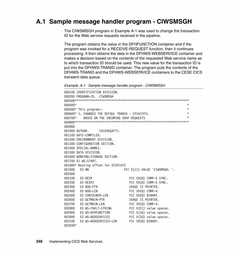
A.1 Sample message handler program - CIWSMSGHThe CIWSMSGH program in Example A-1 was used to change the transaction ID for the Web service requests received in the pipeline.
The program obtains the value in the DFHFUNCTION container and if the program was invoked for a RECEIVE-REQUEST function, then it continues processing. It then obtains the data in the DFHWS-WEBSERVICE container and makes a decision based on the contents of the requested Web service name as to which transaction ID should be used. This new value for the transaction ID is put into the DFHWS-TRANID container. The program puts the contents of the DFHWS-TRANID and the DFHWS-WEBSERVICE containers to the CESE CICS transient data queue.
Example: A-1 Sample message handler program - CIWSMSGH
000100 IDENTIFICATION DIVISION.000200 PROGRAM-ID. CIWSMSGH000300*****************************************************************000400* *000500* This program:- *000600* 1. CHANGES THE DEFAUL TRANID : CPIH/CPIL *000700* BASED ON THE INCOMING SOAP REQUESTS *000800*****************************************************************000900001000 AUTHOR. CHIEREGATTI.001100 DATE-COMPILED.001200 ENVIRONMENT DIVISION.001300 CONFIGURATION SECTION.001400 SPECIAL-NAMES.001500 DATA DIVISION.001600 WORKING-STORAGE SECTION.001700 01 WS-START.001800* Nesting offset for DISPLAYS001900 03 NN PIC X(11) VALUE 'CIWSMSGH: '.002000002100 03 RESP PIC S9(8) COMP-5 SYNC.002200 03 RESP2 PIC S9(8) COMP-5 SYNC.002300 03 BOD-PTR USAGE IS POINTER.002400 03 BOD-LEN PIC S9(8) COMP-4.002500 03 CONTAINER-LEN PIC S9(8) BINARY.002600 03 GETMAIN-PTR USAGE IS POINTER.002700 03 GETMAIN-LEN PIC S9(8) COMP-4.002800 03 WS-FAULT-STRING PIC X(21) value spaces.002900 03 WS-DFHFUNCTION PIC X(16) value spaces.003000 03 WS-WEBSERVICES PIC X(30) value spaces.003100 03 WS-WEBSERVICES-LEN PIC S9(8) BINARY.003200*
346 Implementing CICS Web Services
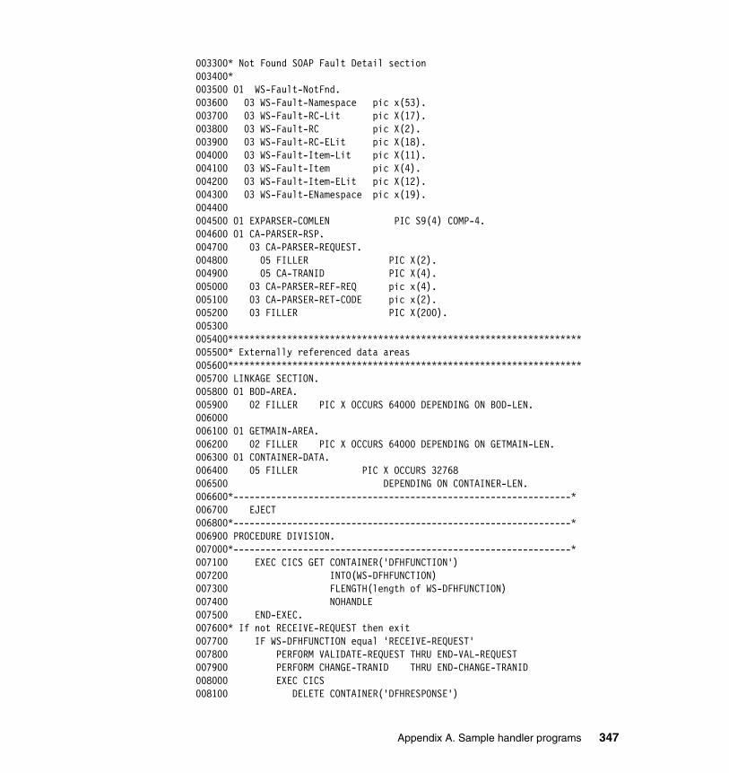
003300* Not Found SOAP Fault Detail section003400*003500 01 WS-Fault-NotFnd.003600 03 WS-Fault-Namespace pic x(53).003700 03 WS-Fault-RC-Lit pic X(17).003800 03 WS-Fault-RC pic X(2).003900 03 WS-Fault-RC-ELit pic X(18).004000 03 WS-Fault-Item-Lit pic X(11).004100 03 WS-Fault-Item pic X(4).004200 03 WS-Fault-Item-ELit pic X(12).004300 03 WS-Fault-ENamespace pic x(19).004400004500 01 EXPARSER-COMLEN PIC S9(4) COMP-4.004600 01 CA-PARSER-RSP.004700 03 CA-PARSER-REQUEST.004800 05 FILLER PIC X(2).004900 05 CA-TRANID PIC X(4).005000 03 CA-PARSER-REF-REQ pic x(4).005100 03 CA-PARSER-RET-CODE pic x(2).005200 03 FILLER PIC X(200).005300005400******************************************************************005500* Externally referenced data areas005600******************************************************************005700 LINKAGE SECTION.005800 01 BOD-AREA.005900 02 FILLER PIC X OCCURS 64000 DEPENDING ON BOD-LEN.006000006100 01 GETMAIN-AREA.006200 02 FILLER PIC X OCCURS 64000 DEPENDING ON GETMAIN-LEN.006300 01 CONTAINER-DATA.006400 05 FILLER PIC X OCCURS 32768006500 DEPENDING ON CONTAINER-LEN.006600*---------------------------------------------------------------*006700 EJECT006800*---------------------------------------------------------------*006900 PROCEDURE DIVISION.007000*---------------------------------------------------------------*007100 EXEC CICS GET CONTAINER('DFHFUNCTION')007200 INTO(WS-DFHFUNCTION)007300 FLENGTH(length of WS-DFHFUNCTION)007400 NOHANDLE007500 END-EXEC.007600* If not RECEIVE-REQUEST then exit007700 IF WS-DFHFUNCTION equal 'RECEIVE-REQUEST'007800 PERFORM VALIDATE-REQUEST THRU END-VAL-REQUEST007900 PERFORM CHANGE-TRANID THRU END-CHANGE-TRANID008000 EXEC CICS008100 DELETE CONTAINER('DFHRESPONSE')
Appendix A. Sample handler programs 347
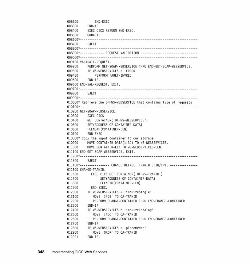
008200 END-EXEC008300 END-IF008400 EXEC CICS RETURN END-EXEC.008500 GOBACK.008600*----------------------------------------------------------------008700 EJECT008800*----------------------------------------------------------------008900*------------- REQUEST VALIDATION -------------------------------009000*----------------------------------------------------------------009100 VALIDATE-REQUEST.009200 PERFORM GET-SOAP-WEBSERVICE THRU END-GET-SOAP-WEBSERVICE.009300 IF WS-WEBSERVICES = 'ERROR'009400 PERFORM FAULT-INVREQ009500 END-IF.009600 END-VAL-REQUEST. EXIT.009700*----------------------------------------------------------------009800 EJECT009900*----------------------------------------------------------------010000* Retrieve the DFHWS-WEBSERVICE that contains type of requests010100*----------------------------------------------------------------010200 GET-SOAP-WEBSERVICE.010300 EXEC CICS010400 GET CONTAINER('DFHWS-WEBSERVICE')010500 SET(ADDRESS OF CONTAINER-DATA)010600 FLENGTH(CONTAINER-LEN)010700 END-EXEC.010800* Copy the input container to our storage010900 MOVE CONTAINER-DATA(1:30) TO WS-WEBSERVICES.011000 MOVE CONTAINER-LEN TO WS-WEBSERVICES-LEN.011100 END-GET-SOAP-WEBSERVICE. EXIT.011200*----------------------------------------------------------------011300 EJECT011400*---------------- CHANGE DEFAULT TRANID CPIH/CPIL ---------------011500 CHANGE-TRANID.011600 EXEC CICS GET CONTAINER('DFHWS-TRANID')011700 SET(ADDRESS OF CONTAINER-DATA)011800 FLENGTH(CONTAINER-LEN)011900 END-EXEC.012000 IF WS-WEBSERVICES = 'inquireSingle'012100 MOVE 'INQS' TO CA-TRANID012200 PERFORM CHANGE-CONTAINER THRU END-CHANGE-CONTAINER012300 END-IF012400 IF WS-WEBSERVICES = 'inquireCatalog'012500 MOVE 'INQC' TO CA-TRANID012600 PERFORM CHANGE-CONTAINER THRU END-CHANGE-CONTAINER012700 END-IF012800 IF WS-WEBSERVICES = 'placeOrder'012900 MOVE 'ORDR' TO CA-TRANID012901 END-IF.
348 Implementing CICS Web Services
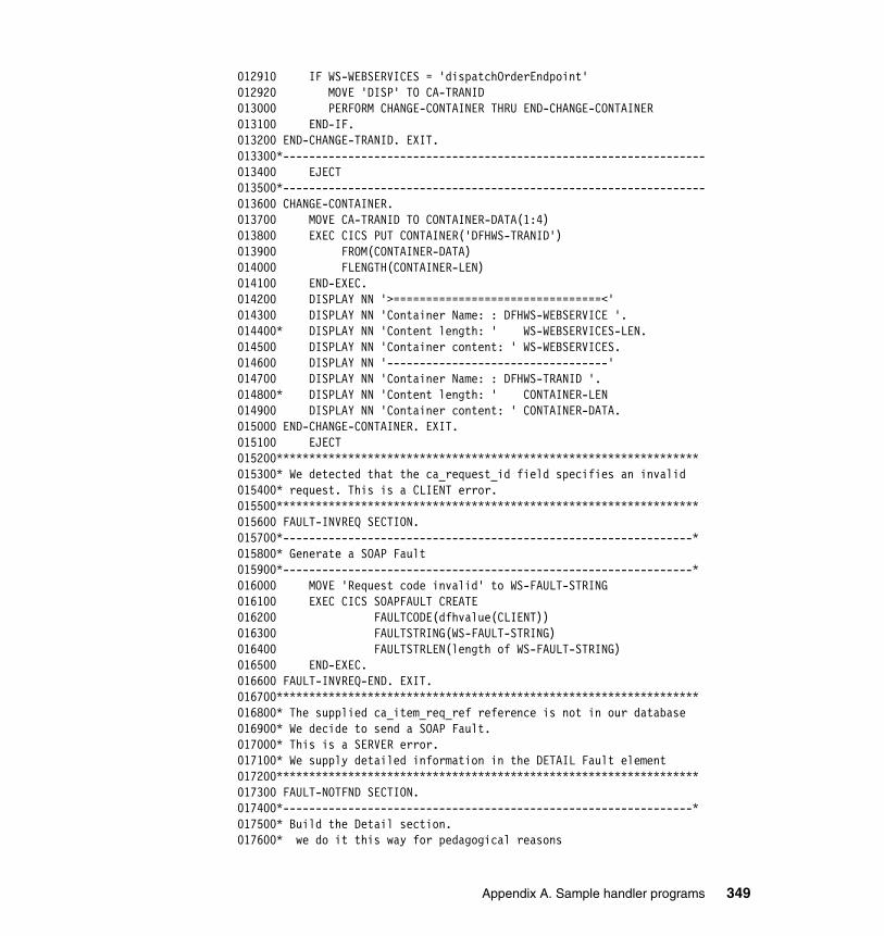
012910 IF WS-WEBSERVICES = 'dispatchOrderEndpoint'012920 MOVE 'DISP' TO CA-TRANID013000 PERFORM CHANGE-CONTAINER THRU END-CHANGE-CONTAINER013100 END-IF.013200 END-CHANGE-TRANID. EXIT.013300*-----------------------------------------------------------------013400 EJECT013500*-----------------------------------------------------------------013600 CHANGE-CONTAINER.013700 MOVE CA-TRANID TO CONTAINER-DATA(1:4)013800 EXEC CICS PUT CONTAINER('DFHWS-TRANID')013900 FROM(CONTAINER-DATA)014000 FLENGTH(CONTAINER-LEN)014100 END-EXEC.014200 DISPLAY NN '>================================<'014300 DISPLAY NN 'Container Name: : DFHWS-WEBSERVICE '.014400* DISPLAY NN 'Content length: ' WS-WEBSERVICES-LEN.014500 DISPLAY NN 'Container content: ' WS-WEBSERVICES.014600 DISPLAY NN '----------------------------------'014700 DISPLAY NN 'Container Name: : DFHWS-TRANID '.014800* DISPLAY NN 'Content length: ' CONTAINER-LEN014900 DISPLAY NN 'Container content: ' CONTAINER-DATA.015000 END-CHANGE-CONTAINER. EXIT.015100 EJECT015200*****************************************************************015300* We detected that the ca_request_id field specifies an invalid015400* request. This is a CLIENT error.015500*****************************************************************015600 FAULT-INVREQ SECTION.015700*---------------------------------------------------------------*015800* Generate a SOAP Fault015900*---------------------------------------------------------------*016000 MOVE 'Request code invalid' to WS-FAULT-STRING016100 EXEC CICS SOAPFAULT CREATE016200 FAULTCODE(dfhvalue(CLIENT))016300 FAULTSTRING(WS-FAULT-STRING)016400 FAULTSTRLEN(length of WS-FAULT-STRING)016500 END-EXEC.016600 FAULT-INVREQ-END. EXIT.016700*****************************************************************016800* The supplied ca_item_req_ref reference is not in our database016900* We decide to send a SOAP Fault.017000* This is a SERVER error.017100* We supply detailed information in the DETAIL Fault element017200*****************************************************************017300 FAULT-NOTFND SECTION.017400*---------------------------------------------------------------*017500* Build the Detail section.017600* we do it this way for pedagogical reasons
Appendix A. Sample handler programs 349
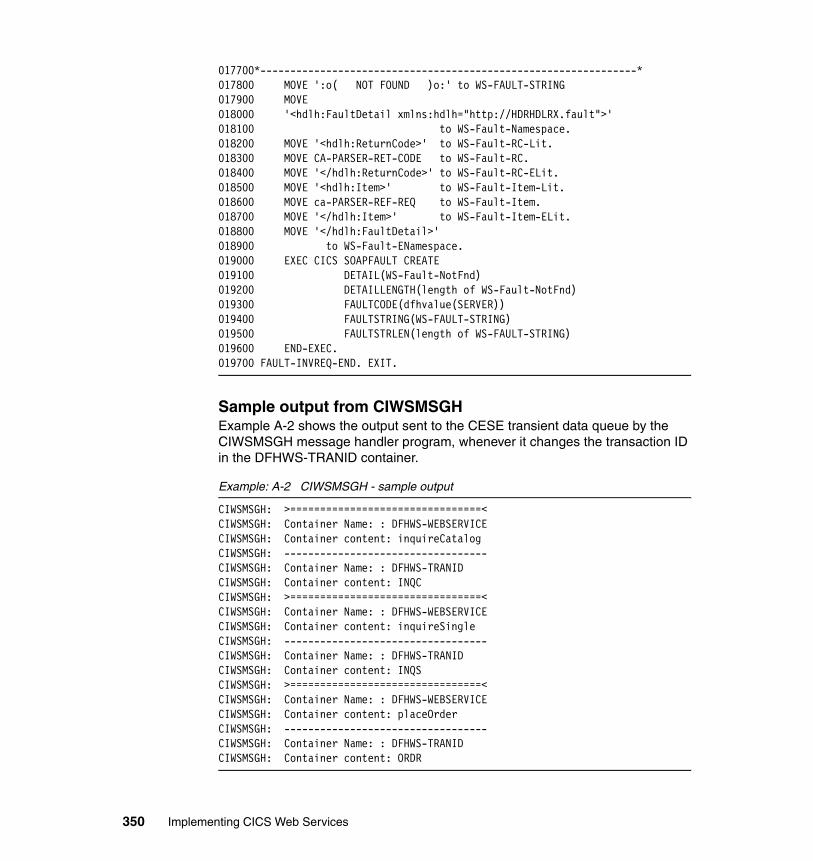
017700*---------------------------------------------------------------*017800 MOVE ':o( NOT FOUND )o:' to WS-FAULT-STRING017900 MOVE018000 '<hdlh:FaultDetail xmlns:hdlh="http://HDRHDLRX.fault">'018100 to WS-Fault-Namespace.018200 MOVE '<hdlh:ReturnCode>' to WS-Fault-RC-Lit.018300 MOVE CA-PARSER-RET-CODE to WS-Fault-RC.018400 MOVE '</hdlh:ReturnCode>' to WS-Fault-RC-ELit.018500 MOVE '<hdlh:Item>' to WS-Fault-Item-Lit.018600 MOVE ca-PARSER-REF-REQ to WS-Fault-Item.018700 MOVE '</hdlh:Item>' to WS-Fault-Item-ELit.018800 MOVE '</hdlh:FaultDetail>'018900 to WS-Fault-ENamespace.019000 EXEC CICS SOAPFAULT CREATE019100 DETAIL(WS-Fault-NotFnd)019200 DETAILLENGTH(length of WS-Fault-NotFnd)019300 FAULTCODE(dfhvalue(SERVER))019400 FAULTSTRING(WS-FAULT-STRING)019500 FAULTSTRLEN(length of WS-FAULT-STRING)019600 END-EXEC.019700 FAULT-INVREQ-END. EXIT.
Sample output from CIWSMSGHExample A-2 shows the output sent to the CESE transient data queue by the CIWSMSGH message handler program, whenever it changes the transaction ID in the DFHWS-TRANID container.
Example: A-2 CIWSMSGH - sample output
CIWSMSGH: >================================< CIWSMSGH: Container Name: : DFHWS-WEBSERVICE CIWSMSGH: Container content: inquireCatalog CIWSMSGH: ---------------------------------- CIWSMSGH: Container Name: : DFHWS-TRANID CIWSMSGH: Container content: INQC CIWSMSGH: >================================< CIWSMSGH: Container Name: : DFHWS-WEBSERVICE CIWSMSGH: Container content: inquireSingle CIWSMSGH: ---------------------------------- CIWSMSGH: Container Name: : DFHWS-TRANID CIWSMSGH: Container content: INQS CIWSMSGH: >================================< CIWSMSGH: Container Name: : DFHWS-WEBSERVICE CIWSMSGH: Container content: placeOrder CIWSMSGH: ---------------------------------- CIWSMSGH: Container Name: : DFHWS-TRANID CIWSMSGH: Container content: ORDR
350 Implementing CICS Web Services
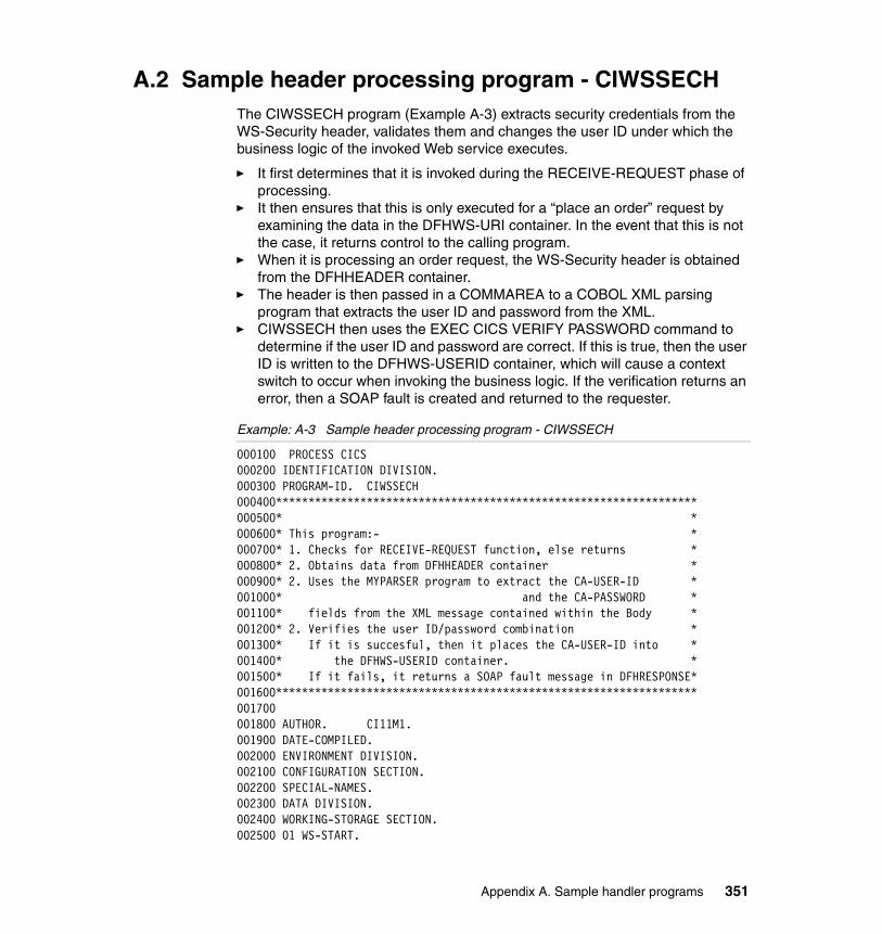
A.2 Sample header processing program - CIWSSECHThe CIWSSECH program (Example A-3) extracts security credentials from the WS-Security header, validates them and changes the user ID under which the business logic of the invoked Web service executes.
� It first determines that it is invoked during the RECEIVE-REQUEST phase of processing.
� It then ensures that this is only executed for a “place an order” request by examining the data in the DFHWS-URI container. In the event that this is not the case, it returns control to the calling program.
� When it is processing an order request, the WS-Security header is obtained from the DFHHEADER container.
� The header is then passed in a COMMAREA to a COBOL XML parsing program that extracts the user ID and password from the XML.
� CIWSSECH then uses the EXEC CICS VERIFY PASSWORD command to determine if the user ID and password are correct. If this is true, then the user ID is written to the DFHWS-USERID container, which will cause a context switch to occur when invoking the business logic. If the verification returns an error, then a SOAP fault is created and returned to the requester.
Example: A-3 Sample header processing program - CIWSSECH
000100 PROCESS CICS000200 IDENTIFICATION DIVISION.000300 PROGRAM-ID. CIWSSECH000400*****************************************************************000500* *000600* This program:- *000700* 1. Checks for RECEIVE-REQUEST function, else returns *000800* 2. Obtains data from DFHHEADER container *000900* 2. Uses the MYPARSER program to extract the CA-USER-ID *001000* and the CA-PASSWORD *001100* fields from the XML message contained within the Body *001200* 2. Verifies the user ID/password combination *001300* If it is succesful, then it places the CA-USER-ID into *001400* the DFHWS-USERID container. *001500* If it fails, it returns a SOAP fault message in DFHRESPONSE*001600*****************************************************************001700001800 AUTHOR. CI11M1.001900 DATE-COMPILED.002000 ENVIRONMENT DIVISION.002100 CONFIGURATION SECTION.002200 SPECIAL-NAMES.002300 DATA DIVISION.002400 WORKING-STORAGE SECTION.002500 01 WS-START.
Appendix A. Sample handler programs 351
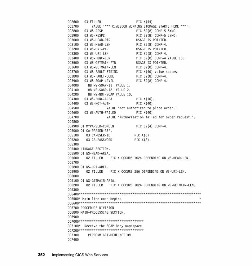
002600 03 FILLER PIC X(44)002700 VALUE '*** CIWSSECH WORKING STORAGE STARTS HERE ***'.002800 03 WS-RESP PIC S9(8) COMP-5 SYNC.002900 03 WS-RESP2 PIC S9(8) COMP-5 SYNC.003000 03 WS-HEAD-PTR USAGE IS POINTER.003100 03 WS-HEAD-LEN PIC S9(8) COMP-4.003200 03 WS-URI-PTR USAGE IS POINTER.003300 03 WS-URI-LEN PIC S9(8) COMP-4.003400 03 WS-FUNC-LEN PIC S9(8) COMP-4 VALUE 16.003500 03 WS-GETMAIN-PTR USAGE IS POINTER.003600 03 WS-GETMAIN-LEN PIC S9(8) COMP-4.003700 03 WS-FAULT-STRING PIC X(40) value spaces.003800 03 WS-FAULT-CODE PIC S9(8) COMP-4.003900 03 WS-SOAP-LEVEL PIC S9(8) COMP-4.004000 88 WS-SOAP-11 VALUE 1.004100 88 WS-SOAP-12 VALUE 2.004200 88 WS-NOT-SOAP VALUE 10.004300 03 WS-FUNC-AREA PIC X(16).004400 03 WS-NOT-AUTH PIC X(40)004500 VALUE 'Not authorized to place order.'.004600 03 WS-AUTH-FAILED PIC X(40)004700 VALUE 'Authorization failed for order request.'.004800004900 01 MYPARSER-COMLEN PIC S9(4) COMP-4.005000 01 CA-PARSER-RSP.005100 03 CA-USER-ID PIC X(8).005200 03 CA-PASSWORD PIC X(8).005300005400 LINKAGE SECTION.005500 01 WS-HEAD-AREA.005600 02 FILLER PIC X OCCURS 1024 DEPENDING ON WS-HEAD-LEN.005700005800 01 WS-URI-AREA.005900 02 FILLER PIC X OCCURS 256 DEPENDING ON WS-URI-LEN.006000006100 01 WS-GETMAIN-AREA.006200 02 FILLER PIC X OCCURS 1024 DEPENDING ON WS-GETMAIN-LEN.006300006400******************************************************************006500* Main line code begins *006600******************************************************************006700 PROCEDURE DIVISION.006800 MAIN-PROCESSING SECTION.006900007000***********************************007100* Receive the SOAP Body namespace007200***********************************007300 PERFORM GET-DFHFUNCTION.007400
352 Implementing CICS Web Services
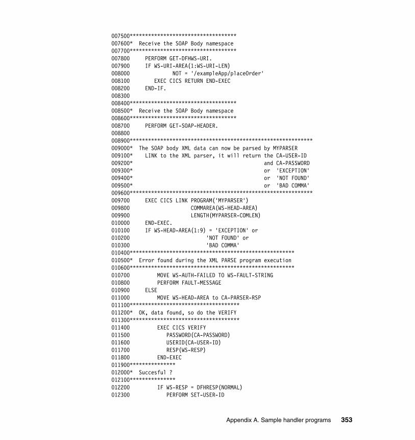
007500***********************************007600* Receive the SOAP Body namespace007700***********************************007800 PERFORM GET-DFHWS-URI.007900 IF WS-URI-AREA(1:WS-URI-LEN)008000 NOT = '/exampleApp/placeOrder'008100 EXEC CICS RETURN END-EXEC008200 END-IF.008300008400***********************************008500* Receive the SOAP Body namespace008600***********************************008700 PERFORM GET-SOAP-HEADER.008800008900************************************************************009000* The SOAP body XML data can now be parsed by MYPARSER009100* LINK to the XML parser, it will return the CA-USER-ID009200* and CA-PASSWORD009300* or 'EXCEPTION'009400* or 'NOT FOUND'009500* or 'BAD COMMA'009600************************************************************009700 EXEC CICS LINK PROGRAM('MYPARSER')009800 COMMAREA(WS-HEAD-AREA)009900 LENGTH(MYPARSER-COMLEN)010000 END-EXEC.010100 IF WS-HEAD-AREA(1:9) = 'EXCEPTION' or010200 'NOT FOUND' or010300 'BAD COMMA'010400******************************************************010500* Error found during the XML PARSE program execution010600******************************************************010700 MOVE WS-AUTH-FAILED TO WS-FAULT-STRING010800 PERFORM FAULT-MESSAGE010900 ELSE011000 MOVE WS-HEAD-AREA to CA-PARSER-RSP011100************************************011200* OK, data found, so do the VERIFY011300************************************011400 EXEC CICS VERIFY011500 PASSWORD(CA-PASSWORD)011600 USERID(CA-USER-ID)011700 RESP(WS-RESP)011800 END-EXEC011900***************012000* Succesful ?012100***************012200 IF WS-RESP = DFHRESP(NORMAL)012300 PERFORM SET-USER-ID
Appendix A. Sample handler programs 353
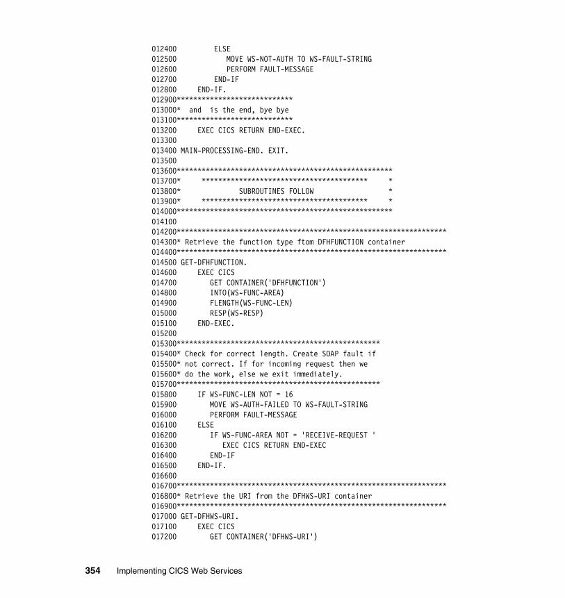
012400 ELSE012500 MOVE WS-NOT-AUTH TO WS-FAULT-STRING012600 PERFORM FAULT-MESSAGE012700 END-IF012800 END-IF.012900****************************013000* and is the end, bye bye013100****************************013200 EXEC CICS RETURN END-EXEC.013300013400 MAIN-PROCESSING-END. EXIT.013500013600****************************************************013700* **************************************** *013800* SUBROUTINES FOLLOW *013900* **************************************** *014000****************************************************014100014200*****************************************************************014300* Retrieve the function type ftom DFHFUNCTION container014400*****************************************************************014500 GET-DFHFUNCTION.014600 EXEC CICS014700 GET CONTAINER('DFHFUNCTION')014800 INTO(WS-FUNC-AREA)014900 FLENGTH(WS-FUNC-LEN)015000 RESP(WS-RESP)015100 END-EXEC.015200015300*************************************************015400* Check for correct length. Create SOAP fault if015500* not correct. If for incoming request then we015600* do the work, else we exit immediately.015700*************************************************015800 IF WS-FUNC-LEN NOT = 16015900 MOVE WS-AUTH-FAILED TO WS-FAULT-STRING016000 PERFORM FAULT-MESSAGE016100 ELSE016200 IF WS-FUNC-AREA NOT = 'RECEIVE-REQUEST '016300 EXEC CICS RETURN END-EXEC016400 END-IF016500 END-IF.016600016700*****************************************************************016800* Retrieve the URI from the DFHWS-URI container016900*****************************************************************017000 GET-DFHWS-URI.017100 EXEC CICS017200 GET CONTAINER('DFHWS-URI')
354 Implementing CICS Web Services
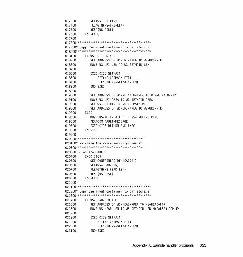
017300 SET(WS-URI-PTR)017400 FLENGTH(WS-URI-LEN)017500 RESP(WS-RESP)017600 END-EXEC.017700017800******************************************017900* Copy the input container to our storage018000******************************************018100 IF WS-URI-LEN > 0018200 SET ADDRESS OF WS-URI-AREA TO WS-URI-PTR018300 MOVE WS-URI-LEN TO WS-GETMAIN-LEN018400018500 EXEC CICS GETMAIN018600 SET(WS-GETMAIN-PTR)018700 FLENGTH(WS-GETMAIN-LEN)018800 END-EXEC018900019000 SET ADDRESS OF WS-GETMAIN-AREA TO WS-GETMAIN-PTR019100 MOVE WS-URI-AREA TO WS-GETMAIN-AREA019200 SET WS-URI-PTR TO WS-GETMAIN-PTR019300 SET ADDRESS OF WS-URI-AREA TO WS-URI-PTR019400 ELSE019500 MOVE WS-AUTH-FAILED TO WS-FAULT-STRING019600 PERFORM FAULT-MESSAGE019700 EXEC CICS RETURN END-EXEC019800 END-IF.019900020000**************************************020100* Retrieve the <wsse:Security> header020200**************************************020300 GET-SOAP-HEADER.020400 EXEC CICS020500 GET CONTAINER('DFHHEADER')020600 SET(WS-HEAD-PTR)020700 FLENGTH(WS-HEAD-LEN)020800 RESP(WS-RESP)020900 END-EXEC.021000021100******************************************021200* Copy the input container to our storage021300******************************************021400 IF WS-HEAD-LEN > 0021500 SET ADDRESS OF WS-HEAD-AREA TO WS-HEAD-PTR021600 MOVE WS-HEAD-LEN TO WS-GETMAIN-LEN MYPARSER-COMLEN021700021800 EXEC CICS GETMAIN021900 SET(WS-GETMAIN-PTR)022000 FLENGTH(WS-GETMAIN-LEN)022100 END-EXEC
Appendix A. Sample handler programs 355
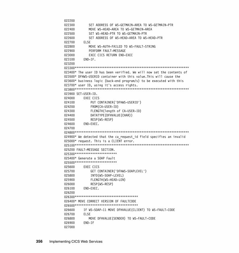
022200022300 SET ADDRESS OF WS-GETMAIN-AREA TO WS-GETMAIN-PTR022400 MOVE WS-HEAD-AREA TO WS-GETMAIN-AREA022500 SET WS-HEAD-PTR TO WS-GETMAIN-PTR022600 SET ADDRESS OF WS-HEAD-AREA TO WS-HEAD-PTR022700 ELSE022800 MOVE WS-AUTH-FAILED TO WS-FAULT-STRING022900 PERFORM FAULT-MESSAGE023000 EXEC CICS RETURN END-EXEC023100 END-IF.023200023300*****************************************************************023400* The user ID has been verified. We will now set the contents of023500* DFHWS-USERID container with this value.This will cause the023600* business logic (back-end program/s) to be executed with this023700* user ID, using it's access rights.023800*****************************************************************023900 SET-USER-ID.024000 EXEC CICS024100 PUT CONTAINER('DFHWS-USERID')024200 FROM(CA-USER-ID)024300 FLENGTH(length of CA-USER-ID)024400 DATATYPE(DFHVALUE(CHAR))024500 RESP(WS-RESP)024600 END-EXEC.024700024800*****************************************************************024900* We detected that the ca_request_id field specifies an invalid025000* request. This is a CLIENT error.025100*****************************************************************025200 FAULT-MESSAGE SECTION.025300************************025400* Generate a SOAP Fault025500************************025600 EXEC CICS025700 GET CONTAINER('DFHWS-SOAPLEVEL')025800 INTO(WS-SOAP-LEVEL)025900 FLENGTH(WS-HEAD-LEN)026000 RESP(WS-RESP)026100 END-EXEC.026200026300************************************026400* MOVE CORRECT VERSION OF FAULTCODE026500************************************026600 IF WS-SOAP-11 MOVE DFHVALUE(CLIENT) TO WS-FAULT-CODE026700 ELSE026800 MOVE DFHVALUE(SENDER) TO WS-FAULT-CODE026900 END-IF027000
356 Implementing CICS Web Services
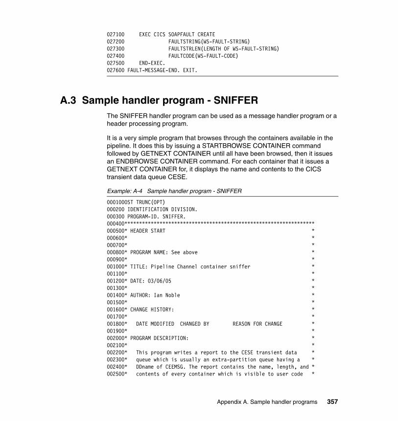
027100 EXEC CICS SOAPFAULT CREATE027200 FAULTSTRING(WS-FAULT-STRING)027300 FAULTSTRLEN(LENGTH OF WS-FAULT-STRING)027400 FAULTCODE(WS-FAULT-CODE)027500 END-EXEC.027600 FAULT-MESSAGE-END. EXIT.
A.3 Sample handler program - SNIFFERThe SNIFFER handler program can be used as a message handler program or a header processing program.
It is a very simple program that browses through the containers available in the pipeline. It does this by issuing a STARTBROWSE CONTAINER command followed by GETNEXT CONTAINER until all have been browsed, then it issues an ENDBROWSE CONTAINER command. For each container that it issues a GETNEXT CONTAINER for, it displays the name and contents to the CICS transient data queue CESE.
Example: A-4 Sample handler program - SNIFFER
000100OST TRUNC(OPT)000200 IDENTIFICATION DIVISION.000300 PROGRAM-ID. SNIFFER.000400*****************************************************************000500* HEADER START *000600* *000700* *000800* PROGRAM NAME: See above *000900* *001000* TITLE: Pipeline Channel container sniffer *001100* *001200* DATE: 03/06/05 *001300* *001400* AUTHOR: Ian Noble *001500* *001600* CHANGE HISTORY: *001700* *001800* DATE MODIFIED CHANGED BY REASON FOR CHANGE *001900* *002000* PROGRAM DESCRIPTION: *002100* *002200* This program writes a report to the CESE transient data *002300* queue which is usually an extra-partition queue having a *002400* DDname of CEEMSG. The report contains the name, length, and *002500* contents of every container which is visible to user code *
Appendix A. Sample handler programs 357
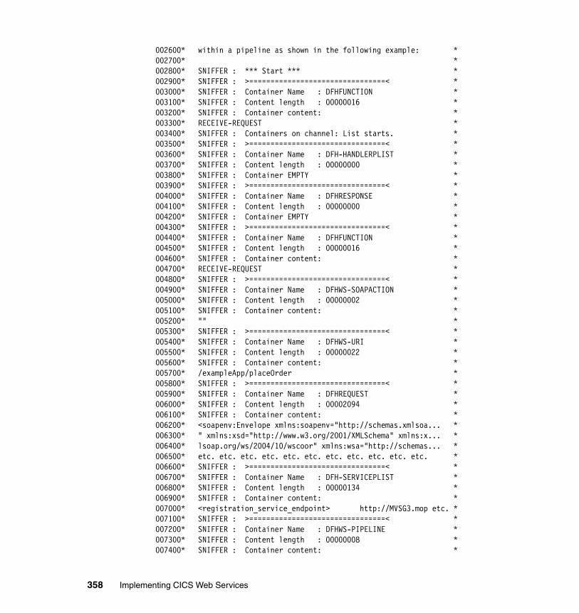
002600* within a pipeline as shown in the following example: *002700* *002800* SNIFFER : *** Start *** *002900* SNIFFER : >================================< *003000* SNIFFER : Container Name : DFHFUNCTION *003100* SNIFFER : Content length : 00000016 *003200* SNIFFER : Container content: *003300* RECEIVE-REQUEST *003400* SNIFFER : Containers on channel: List starts. *003500* SNIFFER : >================================< *003600* SNIFFER : Container Name : DFH-HANDLERPLIST *003700* SNIFFER : Content length : 00000000 *003800* SNIFFER : Container EMPTY *003900* SNIFFER : >================================< *004000* SNIFFER : Container Name : DFHRESPONSE *004100* SNIFFER : Content length : 00000000 *004200* SNIFFER : Container EMPTY *004300* SNIFFER : >================================< *004400* SNIFFER : Container Name : DFHFUNCTION *004500* SNIFFER : Content length : 00000016 *004600* SNIFFER : Container content: *004700* RECEIVE-REQUEST *004800* SNIFFER : >================================< *004900* SNIFFER : Container Name : DFHWS-SOAPACTION *005000* SNIFFER : Content length : 00000002 *005100* SNIFFER : Container content: *005200* "" *005300* SNIFFER : >================================< *005400* SNIFFER : Container Name : DFHWS-URI *005500* SNIFFER : Content length : 00000022 *005600* SNIFFER : Container content: *005700* /exampleApp/placeOrder *005800* SNIFFER : >================================< *005900* SNIFFER : Container Name : DFHREQUEST *006000* SNIFFER : Content length : 00002094 *006100* SNIFFER : Container content: *006200* <soapenv:Envelope xmlns:soapenv="http://schemas.xmlsoa... *006300* " xmlns:xsd="http://www.w3.org/2001/XMLSchema" xmlns:x... *006400* lsoap.org/ws/2004/10/wscoor" xmlns:wsa="http://schemas... *006500* etc. etc. etc. etc. etc. etc. etc. etc. etc. etc. etc. *006600* SNIFFER : >================================< *006700* SNIFFER : Container Name : DFH-SERVICEPLIST *006800* SNIFFER : Content length : 00000134 *006900* SNIFFER : Container content: *007000* <registration_service_endpoint> http://MVSG3.mop etc. *007100* SNIFFER : >================================< *007200* SNIFFER : Container Name : DFHWS-PIPELINE *007300* SNIFFER : Content length : 00000008 *007400* SNIFFER : Container content: *
358 Implementing CICS Web Services
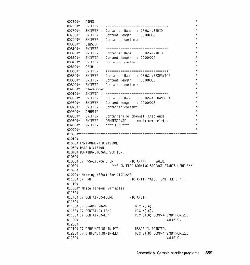
007500* PIPE1 *007600* SNIFFER : >================================< *007700* SNIFFER : Container Name : DFHWS-USERID *007800* SNIFFER : Content length : 00000008 *007900* SNIFFER : Container content: *008000* CIWS3D *008100* SNIFFER : >================================< *008200* SNIFFER : Container Name : DFHWS-TRANID *008300* SNIFFER : Content length : 00000004 *008400* SNIFFER : Container content: *008500* CPIH *008600* SNIFFER : >================================< *008700* SNIFFER : Container Name : DFHWS-WEBSERVICE *008800* SNIFFER : Content length : 00000032 *008900* SNIFFER : Container content: *009000* placeOrder *009100* SNIFFER : >================================< *009200* SNIFFER : Container Name : DFHWS-APPHANDLER *009300* SNIFFER : Content length : 00000008 *009400* SNIFFER : Container content: *009500* DFHPITP *009600* SNIFFER : Containers on channel: List ends *009700* SNIFFER : DFHRESPONSE container deleted *009800* SNIFFER : **** End **** *009900* *010000*****************************************************************010100010200 ENVIRONMENT DIVISION.010300 DATA DIVISION.010400 WORKING-STORAGE SECTION.010500010600 77 WS-EYE-CATCHER PIC X(44) VALUE010700 '*** SNIFFER WORKING STORAGE STARTS HERE ***'.010800010900* Nesting offset for DISPLAYS011000 77 NN PIC X(11) VALUE 'SNIFFER : '.011100011200* Miscellaneous variables011300011400 77 CONTAINER-FOUND PIC X(01).011500011600 77 CHANNEL-NAME PIC X(16).011700 77 CONTAINER-NAME PIC X(16).011800 77 CONTAINER-LEN PIC S9(8) COMP-4 SYNCHRONIZED011900 VALUE 0.012000012100 77 DFHFUNCTION-IN-PTR USAGE IS POINTER.012200 77 DFHFUNCTION-IN-LEN PIC S9(8) COMP-4 SYNCHRONIZED012300 VALUE 0.
Appendix A. Sample handler programs 359
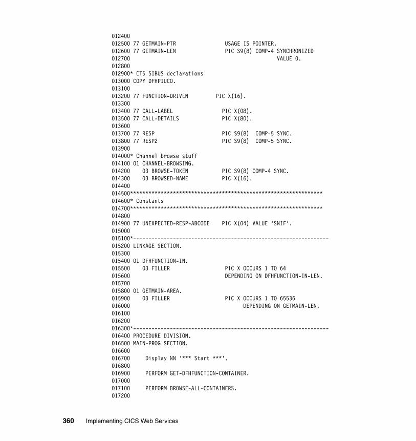
012400012500 77 GETMAIN-PTR USAGE IS POINTER.012600 77 GETMAIN-LEN PIC S9(8) COMP-4 SYNCHRONIZED012700 VALUE 0.012800012900* CTS SIBUS declarations013000 COPY DFHPIUCO.013100013200 77 FUNCTION-DRIVEN PIC X(16).013300013400 77 CALL-LABEL PIC X(08).013500 77 CALL-DETAILS PIC X(80).013600013700 77 RESP PIC S9(8) COMP-5 SYNC.013800 77 RESP2 PIC S9(8) COMP-5 SYNC.013900014000* Channel browse stuff014100 01 CHANNEL-BROWSING.014200 03 BROWSE-TOKEN PIC S9(8) COMP-4 SYNC.014300 03 BROWSED-NAME PIC X(16).014400014500***************************************************************014600* Constants014700***************************************************************014800014900 77 UNEXPECTED-RESP-ABCODE PIC X(04) VALUE 'SNIF'.015000015100*----------------------------------------------------------------015200 LINKAGE SECTION.015300015400 01 DFHFUNCTION-IN.015500 03 FILLER PIC X OCCURS 1 TO 64015600 DEPENDING ON DFHFUNCTION-IN-LEN.015700015800 01 GETMAIN-AREA.015900 03 FILLER PIC X OCCURS 1 TO 65536016000 DEPENDING ON GETMAIN-LEN.016100016200016300*----------------------------------------------------------------016400 PROCEDURE DIVISION.016500 MAIN-PROG SECTION.016600016700 Display NN '*** Start ***'.016800016900 PERFORM GET-DFHFUNCTION-CONTAINER.017000017100 PERFORM BROWSE-ALL-CONTAINERS.017200
360 Implementing CICS Web Services
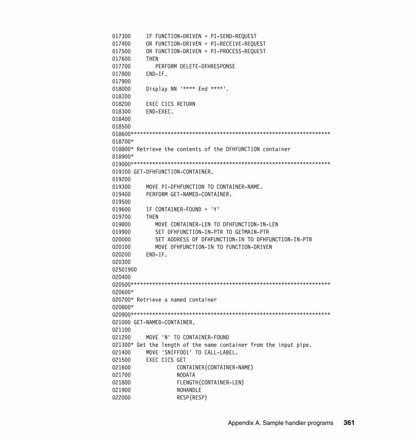
017300 IF FUNCTION-DRIVEN = PI-SEND-REQUEST017400 OR FUNCTION-DRIVEN = PI-RECEIVE-REQUEST017500 OR FUNCTION-DRIVEN = PI-PROCESS-REQUEST017600 THEN017700 PERFORM DELETE-DFHRESPONSE017800 END-IF.017900018000 Display NN '**** End ****'.018100018200 EXEC CICS RETURN018300 END-EXEC.018400018500018600*****************************************************************018700*018800* Retrieve the contents of the DFHFUNCTION container018900*019000*****************************************************************019100 GET-DFHFUNCTION-CONTAINER.019200019300 MOVE PI-DFHFUNCTION TO CONTAINER-NAME.019400 PERFORM GET-NAMED-CONTAINER.019500019600 IF CONTAINER-FOUND = 'Y'019700 THEN019800 MOVE CONTAINER-LEN TO DFHFUNCTION-IN-LEN019900 SET DFHFUNCTION-IN-PTR TO GETMAIN-PTR020000 SET ADDRESS OF DFHFUNCTION-IN TO DFHFUNCTION-IN-PTR020100 MOVE DFHFUNCTION-IN TO FUNCTION-DRIVEN020200 END-IF.020300 02501900020400020500*****************************************************************020600*020700* Retrieve a named container020800*020900*****************************************************************021000 GET-NAMED-CONTAINER.021100021200 MOVE 'N' TO CONTAINER-FOUND021300* Get the length of the name container from the input pipe.021400 MOVE 'SNIFF001' TO CALL-LABEL.021500 EXEC CICS GET021600 CONTAINER(CONTAINER-NAME)021700 NODATA021800 FLENGTH(CONTAINER-LEN)021900 NOHANDLE022000 RESP(RESP)
Appendix A. Sample handler programs 361
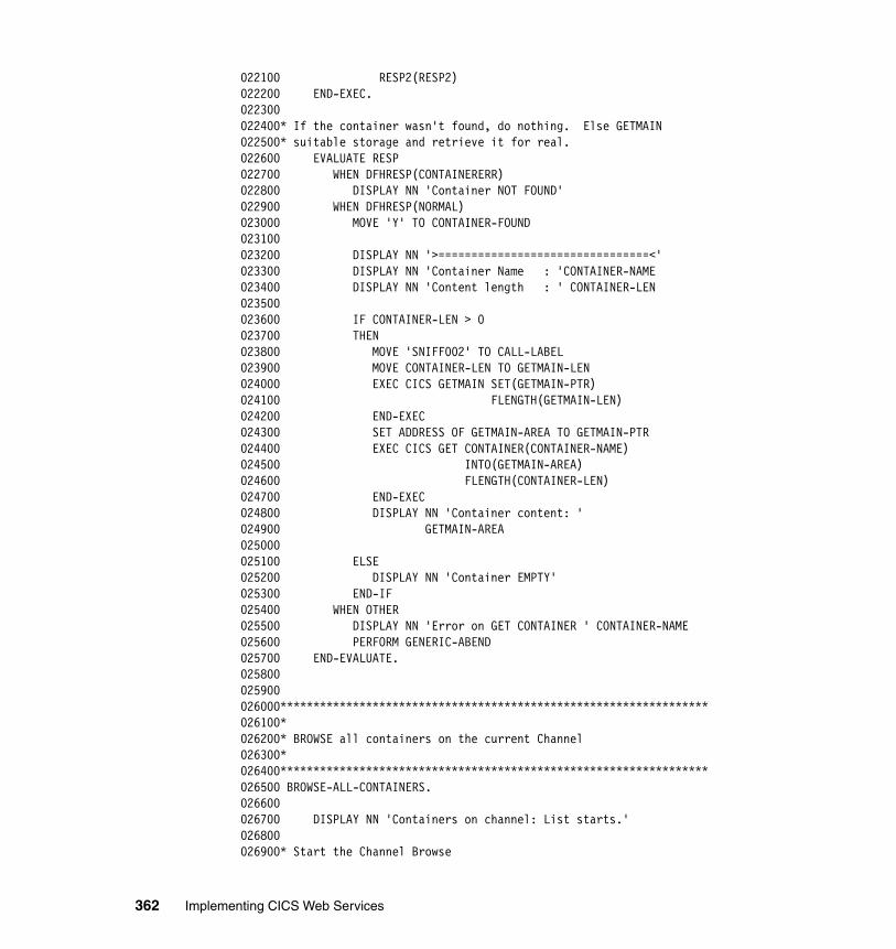
022100 RESP2(RESP2)022200 END-EXEC.022300022400* If the container wasn't found, do nothing. Else GETMAIN022500* suitable storage and retrieve it for real.022600 EVALUATE RESP022700 WHEN DFHRESP(CONTAINERERR)022800 DISPLAY NN 'Container NOT FOUND'022900 WHEN DFHRESP(NORMAL)023000 MOVE 'Y' TO CONTAINER-FOUND023100023200 DISPLAY NN '>================================<'023300 DISPLAY NN 'Container Name : 'CONTAINER-NAME023400 DISPLAY NN 'Content length : ' CONTAINER-LEN023500023600 IF CONTAINER-LEN > 0023700 THEN023800 MOVE 'SNIFF002' TO CALL-LABEL023900 MOVE CONTAINER-LEN TO GETMAIN-LEN024000 EXEC CICS GETMAIN SET(GETMAIN-PTR)024100 FLENGTH(GETMAIN-LEN)024200 END-EXEC024300 SET ADDRESS OF GETMAIN-AREA TO GETMAIN-PTR024400 EXEC CICS GET CONTAINER(CONTAINER-NAME)024500 INTO(GETMAIN-AREA)024600 FLENGTH(CONTAINER-LEN)024700 END-EXEC024800 DISPLAY NN 'Container content: '024900 GETMAIN-AREA025000025100 ELSE025200 DISPLAY NN 'Container EMPTY'025300 END-IF025400 WHEN OTHER025500 DISPLAY NN 'Error on GET CONTAINER ' CONTAINER-NAME025600 PERFORM GENERIC-ABEND025700 END-EVALUATE.025800025900026000*****************************************************************026100*026200* BROWSE all containers on the current Channel026300*026400*****************************************************************026500 BROWSE-ALL-CONTAINERS.026600026700 DISPLAY NN 'Containers on channel: List starts.'026800026900* Start the Channel Browse
362 Implementing CICS Web Services
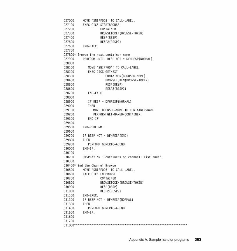
027000 MOVE 'SNIFF003' TO CALL-LABEL.027100 EXEC CICS STARTBROWSE027200 CONTAINER027300 BROWSETOKEN(BROWSE-TOKEN)027400 RESP(RESP)027500 RESP2(RESP2)027600 END-EXEC.027700027800* Browse the next container name027900 PERFORM UNTIL RESP NOT = DFHRESP(NORMAL)028000028100 MOVE 'SNIFF004' TO CALL-LABEL028200 EXEC CICS GETNEXT028300 CONTAINER(BROWSED-NAME)028400 BROWSETOKEN(BROWSE-TOKEN)028500 RESP(RESP)028600 RESP2(RESP2)028700 END-EXEC028800028900 IF RESP = DFHRESP(NORMAL)029000 THEN029100 MOVE BROWSED-NAME TO CONTAINER-NAME029200 PERFORM GET-NAMED-CONTAINER029300 END-IF029400029500 END-PERFORM.029600029700 IF RESP NOT = DFHRESP(END)029800 THEN029900 PERFORM GENERIC-ABEND030000 END-IF.030100030200 DISPLAY NN 'Containers on channel: List ends'.030300030400* End the Channel Browse030500 MOVE 'SNIFF005' TO CALL-LABEL.030600 EXEC CICS ENDBROWSE030700 CONTAINER030800 BROWSETOKEN(BROWSE-TOKEN)030900 RESP(RESP)031000 RESP2(RESP2)031100 END-EXEC.031200 IF RESP NOT = DFHRESP(NORMAL)031300 THEN031400 PERFORM GENERIC-ABEND031500 END-IF.031600031700031800*****************************************************************
Appendix A. Sample handler programs 363
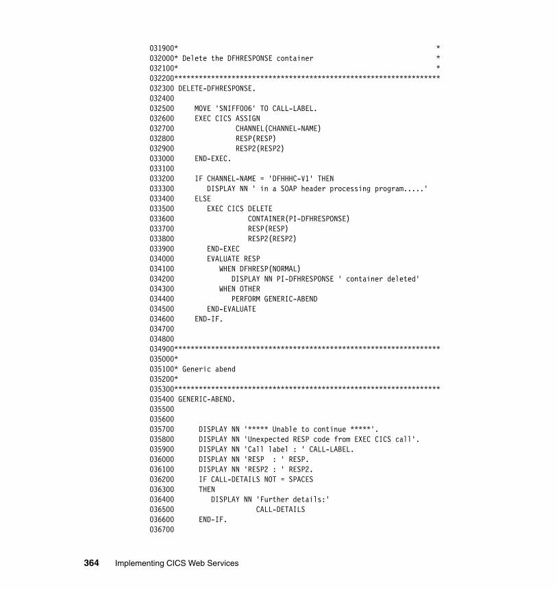
031900* *032000* Delete the DFHRESPONSE container *032100* *032200*****************************************************************032300 DELETE-DFHRESPONSE.032400032500 MOVE 'SNIFF006' TO CALL-LABEL.032600 EXEC CICS ASSIGN032700 CHANNEL(CHANNEL-NAME)032800 RESP(RESP)032900 RESP2(RESP2)033000 END-EXEC.033100033200 IF CHANNEL-NAME = 'DFHHHC-V1' THEN033300 DISPLAY NN ' in a SOAP header processing program.....'033400 ELSE033500 EXEC CICS DELETE033600 CONTAINER(PI-DFHRESPONSE)033700 RESP(RESP)033800 RESP2(RESP2)033900 END-EXEC034000 EVALUATE RESP034100 WHEN DFHRESP(NORMAL)034200 DISPLAY NN PI-DFHRESPONSE ' container deleted'034300 WHEN OTHER034400 PERFORM GENERIC-ABEND034500 END-EVALUATE034600 END-IF.034700034800034900*****************************************************************035000*035100* Generic abend035200*035300*****************************************************************035400 GENERIC-ABEND. 035500035600035700 DISPLAY NN '***** Unable to continue *****'. 035800 DISPLAY NN 'Unexpected RESP code from EXEC CICS call'. 035900 DISPLAY NN 'Call label : ' CALL-LABEL. 036000 DISPLAY NN 'RESP : ' RESP. 036100 DISPLAY NN 'RESP2 : ' RESP2. 036200 IF CALL-DETAILS NOT = SPACES036300 THEN036400 DISPLAY NN 'Further details:'036500 CALL-DETAILS036600 END-IF.036700
364 Implementing CICS Web Services
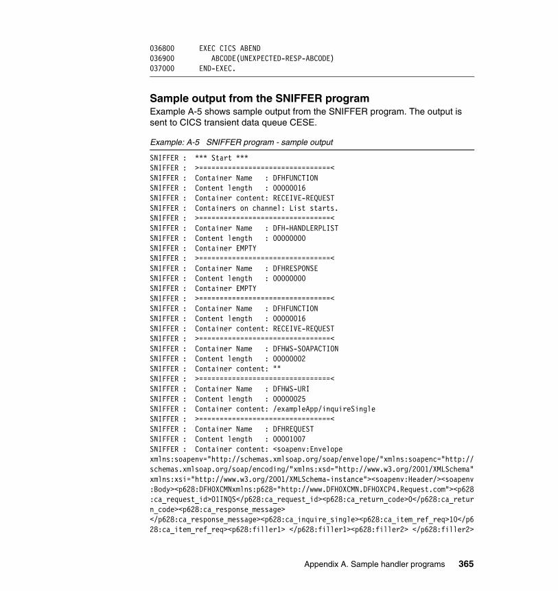
036800 EXEC CICS ABEND 036900 ABCODE(UNEXPECTED-RESP-ABCODE) 037000 END-EXEC.
Sample output from the SNIFFER programExample A-5 shows sample output from the SNIFFER program. The output is sent to CICS transient data queue CESE.
Example: A-5 SNIFFER program - sample output
SNIFFER : *** Start ***SNIFFER : >================================<SNIFFER : Container Name : DFHFUNCTIONSNIFFER : Content length : 00000016SNIFFER : Container content: RECEIVE-REQUESTSNIFFER : Containers on channel: List starts.SNIFFER : >================================<SNIFFER : Container Name : DFH-HANDLERPLISTSNIFFER : Content length : 00000000SNIFFER : Container EMPTYSNIFFER : >================================<SNIFFER : Container Name : DFHRESPONSESNIFFER : Content length : 00000000SNIFFER : Container EMPTYSNIFFER : >================================<SNIFFER : Container Name : DFHFUNCTIONSNIFFER : Content length : 00000016SNIFFER : Container content: RECEIVE-REQUESTSNIFFER : >================================<SNIFFER : Container Name : DFHWS-SOAPACTIONSNIFFER : Content length : 00000002SNIFFER : Container content: ""SNIFFER : >================================<SNIFFER : Container Name : DFHWS-URISNIFFER : Content length : 00000025SNIFFER : Container content: /exampleApp/inquireSingleSNIFFER : >================================<SNIFFER : Container Name : DFHREQUESTSNIFFER : Content length : 00001007SNIFFER : Container content: <soapenv:Envelopexmlns:soapenv="http://schemas.xmlsoap.org/soap/envelope/"xmlns:soapenc="http://schemas.xmlsoap.org/soap/encoding/"xmlns:xsd="http://www.w3.org/2001/XMLSchema"xmlns:xsi="http://www.w3.org/2001/XMLSchema-instance"><soapenv:Header/><soapenv:Body><p628:DFH0XCMNxmlns:p628="http://www.DFH0XCMN.DFH0XCP4.Request.com"><p628:ca_request_id>01INQS</p628:ca_request_id><p628:ca_return_code>0</p628:ca_return_code><p628:ca_response_message> </p628:ca_response_message><p628:ca_inquire_single><p628:ca_item_ref_req>10</p628:ca_item_ref_req><p628:filler1> </p628:filler1><p628:filler2> </p628:filler2>
Appendix A. Sample handler programs 365
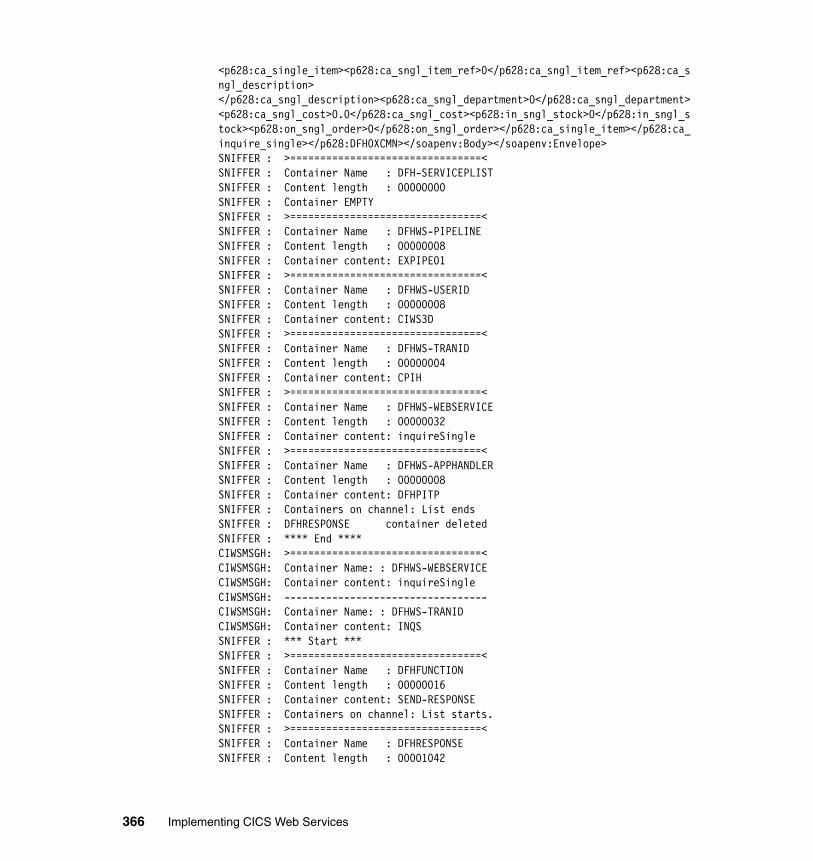
<p628:ca_single_item><p628:ca_sngl_item_ref>0</p628:ca_sngl_item_ref><p628:ca_sngl_description> </p628:ca_sngl_description><p628:ca_sngl_department>0</p628:ca_sngl_department><p628:ca_sngl_cost>0.0</p628:ca_sngl_cost><p628:in_sngl_stock>0</p628:in_sngl_stock><p628:on_sngl_order>0</p628:on_sngl_order></p628:ca_single_item></p628:ca_inquire_single></p628:DFH0XCMN></soapenv:Body></soapenv:Envelope>SNIFFER : >================================<SNIFFER : Container Name : DFH-SERVICEPLISTSNIFFER : Content length : 00000000SNIFFER : Container EMPTYSNIFFER : >================================<SNIFFER : Container Name : DFHWS-PIPELINESNIFFER : Content length : 00000008SNIFFER : Container content: EXPIPE01SNIFFER : >================================<SNIFFER : Container Name : DFHWS-USERIDSNIFFER : Content length : 00000008SNIFFER : Container content: CIWS3DSNIFFER : >================================<SNIFFER : Container Name : DFHWS-TRANIDSNIFFER : Content length : 00000004SNIFFER : Container content: CPIHSNIFFER : >================================<SNIFFER : Container Name : DFHWS-WEBSERVICESNIFFER : Content length : 00000032SNIFFER : Container content: inquireSingleSNIFFER : >================================<SNIFFER : Container Name : DFHWS-APPHANDLERSNIFFER : Content length : 00000008SNIFFER : Container content: DFHPITPSNIFFER : Containers on channel: List endsSNIFFER : DFHRESPONSE container deletedSNIFFER : **** End ****CIWSMSGH: >================================<CIWSMSGH: Container Name: : DFHWS-WEBSERVICECIWSMSGH: Container content: inquireSingleCIWSMSGH: ----------------------------------CIWSMSGH: Container Name: : DFHWS-TRANIDCIWSMSGH: Container content: INQSSNIFFER : *** Start ***SNIFFER : >================================<SNIFFER : Container Name : DFHFUNCTIONSNIFFER : Content length : 00000016SNIFFER : Container content: SEND-RESPONSESNIFFER : Containers on channel: List starts.SNIFFER : >================================<SNIFFER : Container Name : DFHRESPONSESNIFFER : Content length : 00001042
366 Implementing CICS Web Services
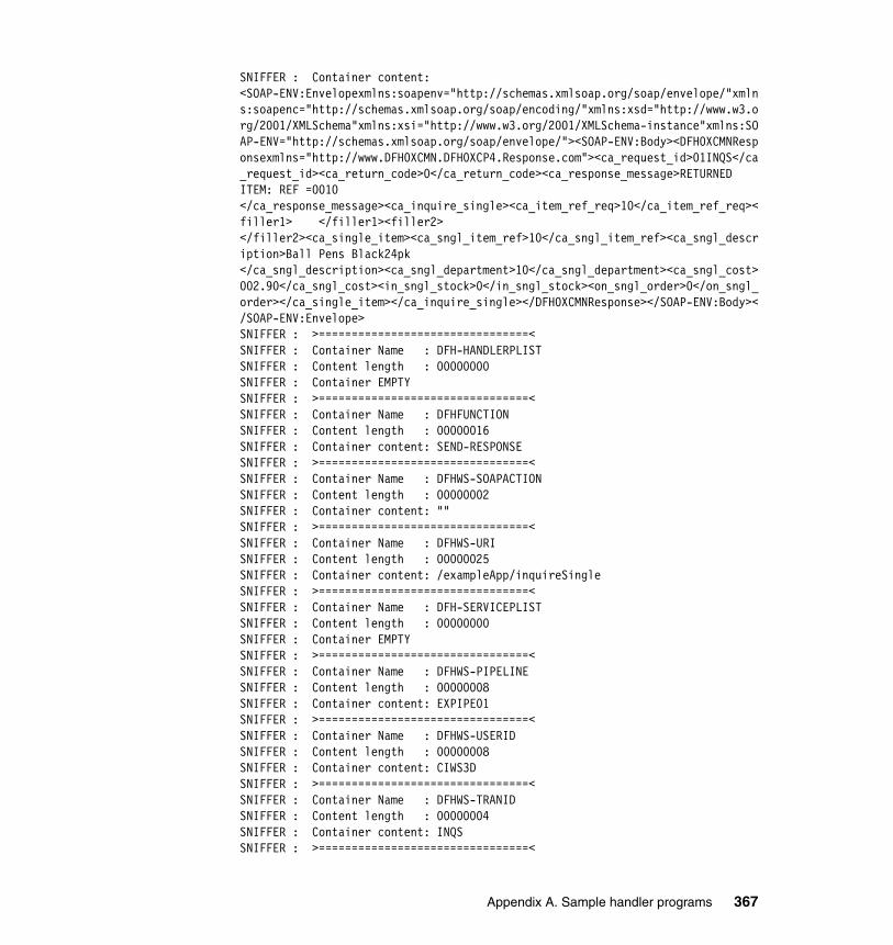
SNIFFER : Container content: <SOAP-ENV:Envelopexmlns:soapenv="http://schemas.xmlsoap.org/soap/envelope/"xmlns:soapenc="http://schemas.xmlsoap.org/soap/encoding/"xmlns:xsd="http://www.w3.org/2001/XMLSchema"xmlns:xsi="http://www.w3.org/2001/XMLSchema-instance"xmlns:SOAP-ENV="http://schemas.xmlsoap.org/soap/envelope/"><SOAP-ENV:Body><DFH0XCMNResponsexmlns="http://www.DFH0XCMN.DFH0XCP4.Response.com"><ca_request_id>01INQS</ca_request_id><ca_return_code>0</ca_return_code><ca_response_message>RETURNED ITEM: REF =0010 </ca_response_message><ca_inquire_single><ca_item_ref_req>10</ca_item_ref_req><filler1> </filler1><filler2> </filler2><ca_single_item><ca_sngl_item_ref>10</ca_sngl_item_ref><ca_sngl_description>Ball Pens Black24pk </ca_sngl_description><ca_sngl_department>10</ca_sngl_department><ca_sngl_cost>002.90</ca_sngl_cost><in_sngl_stock>0</in_sngl_stock><on_sngl_order>0</on_sngl_order></ca_single_item></ca_inquire_single></DFH0XCMNResponse></SOAP-ENV:Body></SOAP-ENV:Envelope>SNIFFER : >================================<SNIFFER : Container Name : DFH-HANDLERPLISTSNIFFER : Content length : 00000000SNIFFER : Container EMPTYSNIFFER : >================================<SNIFFER : Container Name : DFHFUNCTIONSNIFFER : Content length : 00000016SNIFFER : Container content: SEND-RESPONSESNIFFER : >================================<SNIFFER : Container Name : DFHWS-SOAPACTIONSNIFFER : Content length : 00000002SNIFFER : Container content: ""SNIFFER : >================================<SNIFFER : Container Name : DFHWS-URISNIFFER : Content length : 00000025SNIFFER : Container content: /exampleApp/inquireSingleSNIFFER : >================================<SNIFFER : Container Name : DFH-SERVICEPLISTSNIFFER : Content length : 00000000SNIFFER : Container EMPTYSNIFFER : >================================<SNIFFER : Container Name : DFHWS-PIPELINESNIFFER : Content length : 00000008SNIFFER : Container content: EXPIPE01SNIFFER : >================================<SNIFFER : Container Name : DFHWS-USERIDSNIFFER : Content length : 00000008SNIFFER : Container content: CIWS3DSNIFFER : >================================<SNIFFER : Container Name : DFHWS-TRANIDSNIFFER : Content length : 00000004SNIFFER : Container content: INQSSNIFFER : >================================<
Appendix A. Sample handler programs 367
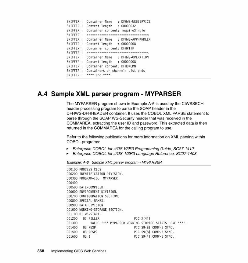
SNIFFER : Container Name : DFHWS-WEBSERVICESNIFFER : Content length : 00000032SNIFFER : Container content: inquireSingleSNIFFER : >================================<SNIFFER : Container Name : DFHWS-APPHANDLERSNIFFER : Content length : 00000008SNIFFER : Container content: DFHPITPSNIFFER : >================================<SNIFFER : Container Name : DFHWS-OPERATIONSNIFFER : Content length : 00000008SNIFFER : Container content: DFH0XCMNSNIFFER : Containers on channel: List endsSNIFFER : **** End ****
A.4 Sample XML parser program - MYPARSERThe MYPARSER program shown in Example A-6 is used by the CIWSSECH header processing program to parse the SOAP header in the DFHWS-DFHHEADER container. It uses the COBOL XML PARSE statement to parse through the SOAP WS-Security header that was received in the COMMAREA, extracting the user ID and password. This extracted data is then returned in the COMMAREA for the calling program to use.
Refer to the following publications for more information on XML parsing within COBOL programs:
� Enterprise COBOL for z/OS V3R3 Programming Guide, SC27-1412� Enterprise COBOL for z/OS V3R3 Language Reference, SC27-1408
Example: A-6 Sample XML parser program - MYPARSER
000100 PROCESS CICS000200 IDENTIFICATION DIVISION.000300 PROGRAM-ID. MYPARSER000400000500 DATE-COMPILED.000600 ENVIRONMENT DIVISION.000700 CONFIGURATION SECTION.000800 SPECIAL-NAMES.000900 DATA DIVISION.001000 WORKING-STORAGE SECTION.001100 01 WS-START.001200 03 FILLER PIC X(44)001300 VALUE '*** MYPARSER WORKING STORAGE STARTS HERE ***'.001400 03 RESP PIC S9(8) COMP-5 SYNC.001500 03 RESP2 PIC S9(8) COMP-5 SYNC.001600 03 I PIC S9(4) COMP-5 SYNC.
368 Implementing CICS Web Services
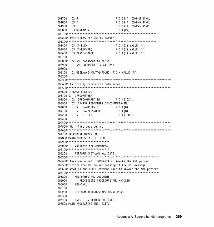
001700 03 J PIC S9(4) COMP-5 SYNC.001800 03 K PIC S9(4) COMP-5 SYNC.001900 03 L PIC S9(4) COMP-5 SYNC.002000 03 WORKAREA PIC X(24).002100*********************************************************002200* Data items for use by parser002300*********************************************************002400 03 IN-ELEM PIC X(1) VALUE 'N'.002500 03 IN-REF-REQ PIC X(1) VALUE 'N'.002600 03 PARSE-ERROR PIC X(1) VALUE 'N'.002700002800* The XML document to parse002900 01 XML-DOCUMENT PIC X(1024).003000003100 01 USERNAME-XMLTAG-FOUND PIC X VALUE 'N'.003200003300******************************************************************003400* Externally referenced data areas003500******************************************************************003600 LINKAGE SECTION.003700 01 DFHCOMMAREA.003800 02 DFHCOMMAREA-IN PIC X(1024).003900 02 CA-RSP REDEFINES DFHCOMMAREA-IN.004000 05 CA-USER-ID PIC X(8).004100 05 CA-PASSWORD PIC X(8).004200 05 FILLER PIC X(1008).004300004400******************************************************************004500* Main line code begins *004600******************************************************************004700 PROCEDURE DIVISION.004800 MAIN-PROCESSING SECTION.004900***************************005000* Validate the commarea005100***************************005200 PERFORM INIT-AND-VALIDATE.005300***********************************************************005400* Received a valid COMMAREA so invoke the XML parser005500* invoke the XML parser passing it the XML message005600* What is the COBOL command used to invoke the XML parser?005700***********************************************************005800 XML PARSE XML-DOCUMENT005900 PROCESSING PROCEDURE XML-HANDLER006000 END-XML.006100006200 PERFORM RETURN-SOAP-LAB-RESPONSE.006300006400 EXEC CICS RETURN END-EXEC.006500 MAIN-PROCESSING-END. EXIT.
Appendix A. Sample handler programs 369
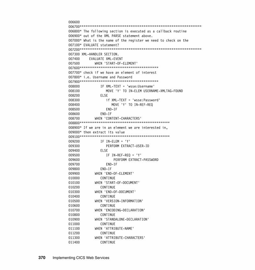
006600006700*****************************************************************006800* The following section is executed as a callback routine006900* out of the XML PARSE statement above.007000* What is the name of the register we need to check on the007100* EVALUATE statement?007200*****************************************************************007300 XML-HANDLER SECTION.007400 EVALUATE XML-EVENT007500 WHEN 'START-OF-ELEMENT'007600******************************************007700* check if we have an element of interest007800* i.e. Username and Password007900******************************************008000 IF XML-TEXT = 'wsse:Username'008100 MOVE 'Y' TO IN-ELEM USERNAME-XMLTAG-FOUND008200 ELSE008300 if XML-TEXT = 'wsse:Password'008400 MOVE 'Y' TO IN-REF-REQ008500 END-IF008600 END-IF008700 WHEN 'CONTENT-CHARACTERS'008800************************************************008900* If we are in an element we are interested in,009000* then extract its value009100************************************************009200 IF IN-ELEM = 'Y'009300 PERFORM EXTRACT-USER-ID009400 ELSE009500 IF IN-REF-REQ = 'Y'009600 PERFORM EXTRACT-PASSWORD009700 END-IF009800 END-IF009900 WHEN 'END-OF-ELEMENT'010000 CONTINUE010100 WHEN 'START-OF-DOCUMENT'010200 CONTINUE010300 WHEN 'END-OF-DOCUMENT'010400 CONTINUE010500 WHEN 'VERSION-INFORMATION'010600 CONTINUE010700 WHEN 'ENCODING-DECLARATION'010800 CONTINUE010900 WHEN 'STANDALONE-DECLARATION'011000 CONTINUE011100 WHEN 'ATTRIBUTE-NAME'011200 CONTINUE011300 WHEN 'ATTRIBUTE-CHARACTERS'011400 CONTINUE
370 Implementing CICS Web Services
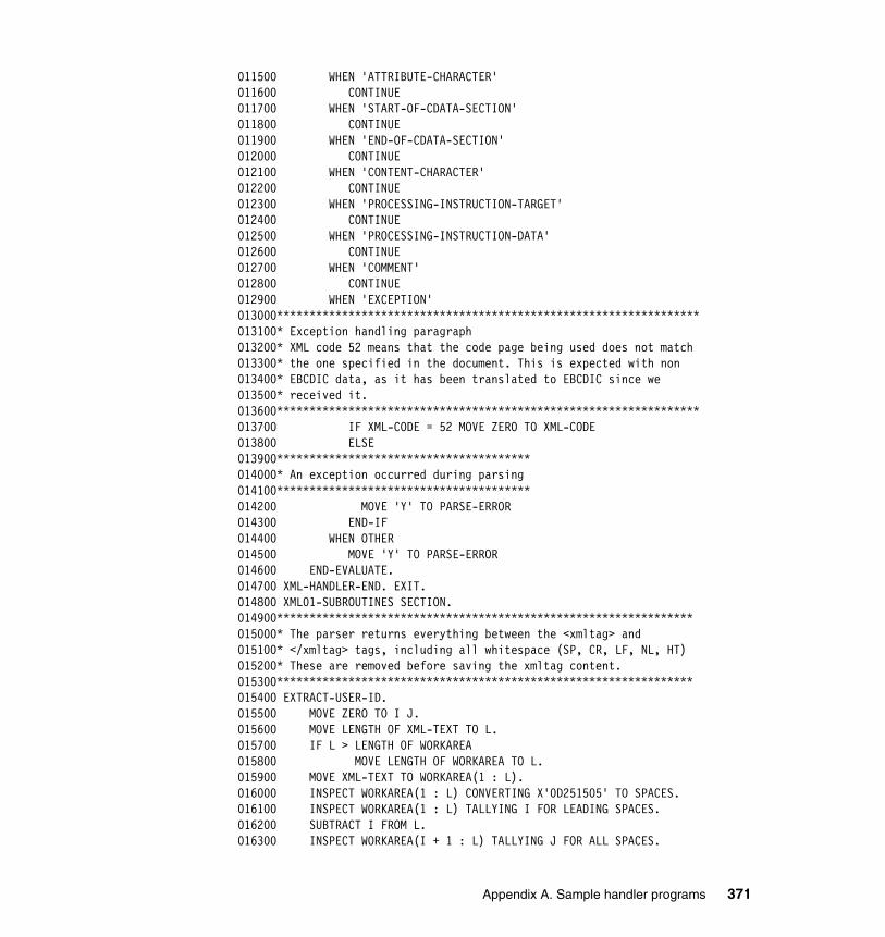
011500 WHEN 'ATTRIBUTE-CHARACTER'011600 CONTINUE011700 WHEN 'START-OF-CDATA-SECTION'011800 CONTINUE011900 WHEN 'END-OF-CDATA-SECTION'012000 CONTINUE012100 WHEN 'CONTENT-CHARACTER'012200 CONTINUE012300 WHEN 'PROCESSING-INSTRUCTION-TARGET'012400 CONTINUE012500 WHEN 'PROCESSING-INSTRUCTION-DATA'012600 CONTINUE012700 WHEN 'COMMENT'012800 CONTINUE012900 WHEN 'EXCEPTION'013000*****************************************************************013100* Exception handling paragraph013200* XML code 52 means that the code page being used does not match013300* the one specified in the document. This is expected with non013400* EBCDIC data, as it has been translated to EBCDIC since we013500* received it.013600*****************************************************************013700 IF XML-CODE = 52 MOVE ZERO TO XML-CODE013800 ELSE013900***************************************014000* An exception occurred during parsing014100***************************************014200 MOVE 'Y' TO PARSE-ERROR014300 END-IF014400 WHEN OTHER014500 MOVE 'Y' TO PARSE-ERROR014600 END-EVALUATE.014700 XML-HANDLER-END. EXIT.014800 XML01-SUBROUTINES SECTION.014900****************************************************************015000* The parser returns everything between the <xmltag> and015100* </xmltag> tags, including all whitespace (SP, CR, LF, NL, HT)015200* These are removed before saving the xmltag content.015300****************************************************************015400 EXTRACT-USER-ID.015500 MOVE ZERO TO I J.015600 MOVE LENGTH OF XML-TEXT TO L.015700 IF L > LENGTH OF WORKAREA015800 MOVE LENGTH OF WORKAREA TO L.015900 MOVE XML-TEXT TO WORKAREA(1 : L).016000 INSPECT WORKAREA(1 : L) CONVERTING X'0D251505' TO SPACES.016100 INSPECT WORKAREA(1 : L) TALLYING I FOR LEADING SPACES.016200 SUBTRACT I FROM L.016300 INSPECT WORKAREA(I + 1 : L) TALLYING J FOR ALL SPACES.
Appendix A. Sample handler programs 371
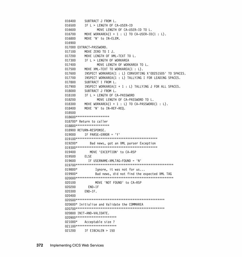
016400 SUBTRACT J FROM L.016500 IF L > LENGTH OF CA-USER-ID016600 MOVE LENGTH OF CA-USER-ID TO L.016700 MOVE WORKAREA(I + 1 : L) TO CA-USER-ID(1 : L).016800 MOVE 'N' to IN-ELEM.016900017000 EXTRACT-PASSWORD.017100 MOVE ZERO TO I J.017200 MOVE LENGTH OF XML-TEXT TO L.017300 IF L > LENGTH OF WORKAREA017400 MOVE LENGTH OF WORKAREA TO L.017500 MOVE XML-TEXT TO WORKAREA(1 : L).017600 INSPECT WORKAREA(1 : L) CONVERTING X'0D251505' TO SPACES.017700 INSPECT WORKAREA(1 : L) TALLYING I FOR LEADING SPACES.017800 SUBTRACT I FROM L.017900 INSPECT WORKAREA(I + 1 : L) TALLYING J FOR ALL SPACES.018000 SUBTRACT J FROM L.018100 IF L > LENGTH OF CA-PASSWORD018200 MOVE LENGTH OF CA-PASSWORD TO L.018300 MOVE WORKAREA(I + 1 : L) TO CA-PASSWORD(1 : L).018400 MOVE 'N' to IN-REF-REQ.018500018600*******************018700* Return to caller018800*******************018900 RETURN-RESPONSE.019000 IF PARSE-ERROR = 'Y'019100**********************************************019200* Bad news, got an XML parser Exception019300**********************************************019400 MOVE 'EXCEPTION' to CA-RSP019500 ELSE019600 IF USERNAME-XMLTAG-FOUND = 'N'019700*******************************************************019800* Ignore, it was not for us...019900* Bad news, did not find the expected XML TAG020000*******************************************************020100 MOVE 'NOT FOUND' to CA-RSP020200 END-IF020300 END-IF.020400020500**************************************************020600* Initialise and Validate the COMMAREA020700**************************************************020800 INIT-AND-VALIDATE.020900***********************021000* Acceptable size ?021100***********************021200 IF EIBCALEN > 150
372 Implementing CICS Web Services
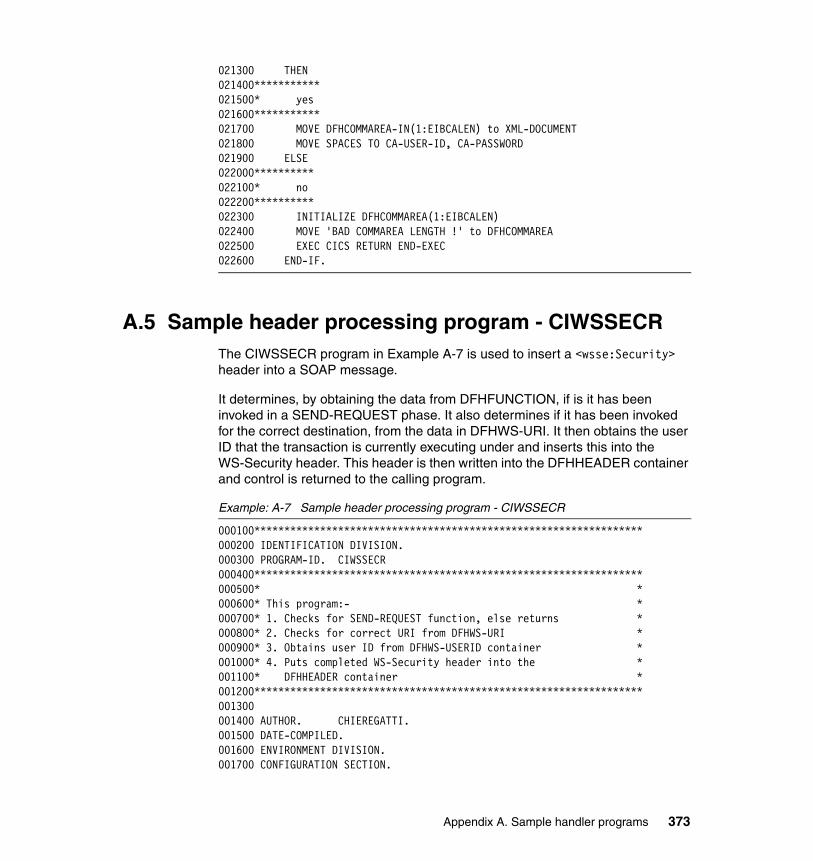
021300 THEN021400***********021500* yes021600***********021700 MOVE DFHCOMMAREA-IN(1:EIBCALEN) to XML-DOCUMENT021800 MOVE SPACES TO CA-USER-ID, CA-PASSWORD021900 ELSE022000**********022100* no022200**********022300 INITIALIZE DFHCOMMAREA(1:EIBCALEN)022400 MOVE 'BAD COMMAREA LENGTH !' to DFHCOMMAREA022500 EXEC CICS RETURN END-EXEC022600 END-IF.
A.5 Sample header processing program - CIWSSECRThe CIWSSECR program in Example A-7 is used to insert a <wsse:Security> header into a SOAP message.
It determines, by obtaining the data from DFHFUNCTION, if is it has been invoked in a SEND-REQUEST phase. It also determines if it has been invoked for the correct destination, from the data in DFHWS-URI. It then obtains the user ID that the transaction is currently executing under and inserts this into the WS-Security header. This header is then written into the DFHHEADER container and control is returned to the calling program.
Example: A-7 Sample header processing program - CIWSSECR
000100*****************************************************************000200 IDENTIFICATION DIVISION.000300 PROGRAM-ID. CIWSSECR000400*****************************************************************000500* *000600* This program:- *000700* 1. Checks for SEND-REQUEST function, else returns *000800* 2. Checks for correct URI from DFHWS-URI *000900* 3. Obtains user ID from DFHWS-USERID container *001000* 4. Puts completed WS-Security header into the *001100* DFHHEADER container *001200*****************************************************************001300001400 AUTHOR. CHIEREGATTI.001500 DATE-COMPILED.001600 ENVIRONMENT DIVISION.001700 CONFIGURATION SECTION.
Appendix A. Sample handler programs 373
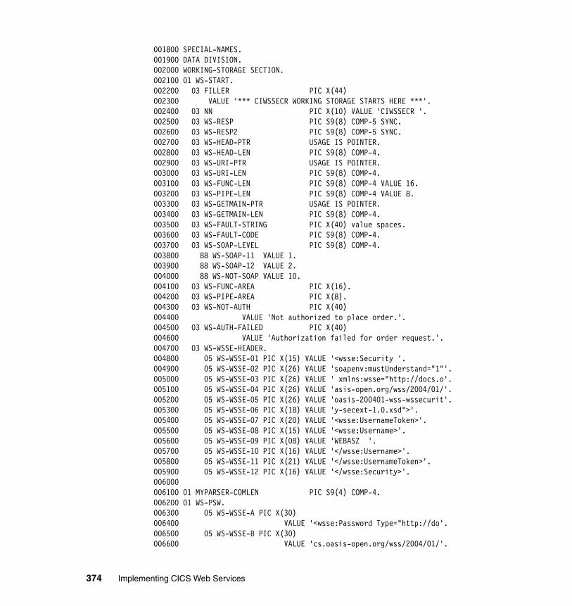
001800 SPECIAL-NAMES.001900 DATA DIVISION.002000 WORKING-STORAGE SECTION.002100 01 WS-START.002200 03 FILLER PIC X(44)002300 VALUE '*** CIWSSECR WORKING STORAGE STARTS HERE ***'.002400 03 NN PIC X(10) VALUE 'CIWSSECR '.002500 03 WS-RESP PIC S9(8) COMP-5 SYNC.002600 03 WS-RESP2 PIC S9(8) COMP-5 SYNC.002700 03 WS-HEAD-PTR USAGE IS POINTER.002800 03 WS-HEAD-LEN PIC S9(8) COMP-4.002900 03 WS-URI-PTR USAGE IS POINTER.003000 03 WS-URI-LEN PIC S9(8) COMP-4.003100 03 WS-FUNC-LEN PIC S9(8) COMP-4 VALUE 16.003200 03 WS-PIPE-LEN PIC S9(8) COMP-4 VALUE 8.003300 03 WS-GETMAIN-PTR USAGE IS POINTER.003400 03 WS-GETMAIN-LEN PIC S9(8) COMP-4.003500 03 WS-FAULT-STRING PIC X(40) value spaces.003600 03 WS-FAULT-CODE PIC S9(8) COMP-4.003700 03 WS-SOAP-LEVEL PIC S9(8) COMP-4.003800 88 WS-SOAP-11 VALUE 1.003900 88 WS-SOAP-12 VALUE 2.004000 88 WS-NOT-SOAP VALUE 10.004100 03 WS-FUNC-AREA PIC X(16).004200 03 WS-PIPE-AREA PIC X(8).004300 03 WS-NOT-AUTH PIC X(40)004400 VALUE 'Not authorized to place order.'.004500 03 WS-AUTH-FAILED PIC X(40)004600 VALUE 'Authorization failed for order request.'.004700 03 WS-WSSE-HEADER.004800 05 WS-WSSE-01 PIC X(15) VALUE '<wsse:Security '.004900 05 WS-WSSE-02 PIC X(26) VALUE 'soapenv:mustUnderstand="1"'.005000 05 WS-WSSE-03 PIC X(26) VALUE ' xmlns:wsse="http://docs.o'.005100 05 WS-WSSE-04 PIC X(26) VALUE 'asis-open.org/wss/2004/01/'.005200 05 WS-WSSE-05 PIC X(26) VALUE 'oasis-200401-wss-wssecurit'.005300 05 WS-WSSE-06 PIC X(18) VALUE 'y-secext-1.0.xsd">'.005400 05 WS-WSSE-07 PIC X(20) VALUE '<wsse:UsernameToken>'.005500 05 WS-WSSE-08 PIC X(15) VALUE '<wsse:Username>'.005600 05 WS-WSSE-09 PIC X(08) VALUE 'WEBASZ '.005700 05 WS-WSSE-10 PIC X(16) VALUE '</wsse:Username>'.005800 05 WS-WSSE-11 PIC X(21) VALUE '</wsse:UsernameToken>'.005900 05 WS-WSSE-12 PIC X(16) VALUE '</wsse:Security>'.006000006100 01 MYPARSER-COMLEN PIC S9(4) COMP-4.006200 01 WS-PSW.006300 05 WS-WSSE-A PIC X(30)006400 VALUE '<wsse:Password Type="http://do'.006500 05 WS-WSSE-B PIC X(30)006600 VALUE 'cs.oasis-open.org/wss/2004/01/'.
374 Implementing CICS Web Services
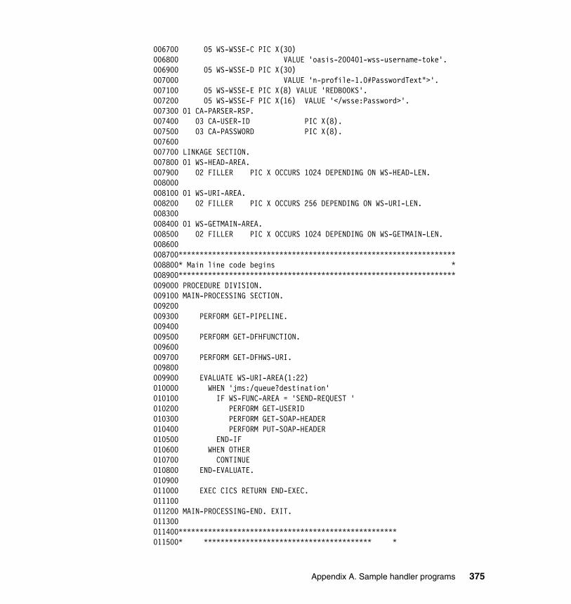
006700 05 WS-WSSE-C PIC X(30)006800 VALUE 'oasis-200401-wss-username-toke'.006900 05 WS-WSSE-D PIC X(30)007000 VALUE 'n-profile-1.0#PasswordText">'.007100 05 WS-WSSE-E PIC X(8) VALUE 'REDB00KS'.007200 05 WS-WSSE-F PIC X(16) VALUE '</wsse:Password>'.007300 01 CA-PARSER-RSP.007400 03 CA-USER-ID PIC X(8).007500 03 CA-PASSWORD PIC X(8).007600007700 LINKAGE SECTION.007800 01 WS-HEAD-AREA.007900 02 FILLER PIC X OCCURS 1024 DEPENDING ON WS-HEAD-LEN.008000008100 01 WS-URI-AREA.008200 02 FILLER PIC X OCCURS 256 DEPENDING ON WS-URI-LEN.008300008400 01 WS-GETMAIN-AREA.008500 02 FILLER PIC X OCCURS 1024 DEPENDING ON WS-GETMAIN-LEN.008600008700******************************************************************008800* Main line code begins *008900******************************************************************009000 PROCEDURE DIVISION.009100 MAIN-PROCESSING SECTION.009200009300 PERFORM GET-PIPELINE.009400009500 PERFORM GET-DFHFUNCTION.009600009700 PERFORM GET-DFHWS-URI.009800009900 EVALUATE WS-URI-AREA(1:22)010000 WHEN 'jms:/queue?destination'010100 IF WS-FUNC-AREA = 'SEND-REQUEST '010200 PERFORM GET-USERID010300 PERFORM GET-SOAP-HEADER010400 PERFORM PUT-SOAP-HEADER010500 END-IF010600 WHEN OTHER010700 CONTINUE010800 END-EVALUATE.010900011000 EXEC CICS RETURN END-EXEC.011100011200 MAIN-PROCESSING-END. EXIT.011300011400****************************************************011500* **************************************** *
Appendix A. Sample handler programs 375
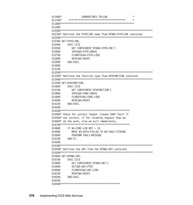
011600* SUBROUTINES FOLLOW *011700* **************************************** *011800****************************************************011900012000*****************************************************************012100* Retrieve the PIPELINE name ftom DFHWS-PIPELINE container012200*****************************************************************012300 GET-PIPELINE.012400 EXEC CICS012500 GET CONTAINER('DFHWS-PIPELINE')012600 INTO(WS-PIPE-AREA)012700 FLENGTH(WS-PIPE-LEN)012800 RESP(WS-RESP)012900 END-EXEC.013000013100013200*****************************************************************013300* Retrieve the function type ftom DFHFUNCTION container013400*****************************************************************013500 GET-DFHFUNCTION.013600 EXEC CICS013700 GET CONTAINER('DFHFUNCTION')013800 INTO(WS-FUNC-AREA)013900 FLENGTH(WS-FUNC-LEN)014000 RESP(WS-RESP)014100 END-EXEC.014200014300*************************************************014400* Check for correct length. Create SOAP fault if014500* not correct. If for incoming request then we014600* do the work, else we exit immediately.014700*************************************************014800 IF WS-FUNC-LEN NOT = 16014900 MOVE WS-AUTH-FAILED TO WS-FAULT-STRING015000 PERFORM FAULT-MESSAGE015100 END-IF.015200015300*****************************************************************015400* Retrieve the URI from the DFHWS-URI container015500*****************************************************************015600 GET-DFHWS-URI.015700 EXEC CICS015800 GET CONTAINER('DFHWS-URI')015900 SET(WS-URI-PTR)016000 FLENGTH(WS-URI-LEN)016100 RESP(WS-RESP)016200 END-EXEC.016300016400******************************************
376 Implementing CICS Web Services
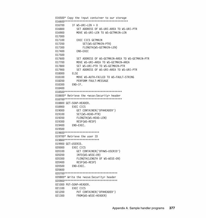
016500* Copy the input container to our storage016600******************************************016700 IF WS-URI-LEN > 0016800 SET ADDRESS OF WS-URI-AREA TO WS-URI-PTR016900 MOVE WS-URI-LEN TO WS-GETMAIN-LEN017000017100 EXEC CICS GETMAIN017200 SET(WS-GETMAIN-PTR)017300 FLENGTH(WS-GETMAIN-LEN)017400 END-EXEC017500017600 SET ADDRESS OF WS-GETMAIN-AREA TO WS-GETMAIN-PTR017700 MOVE WS-URI-AREA TO WS-GETMAIN-AREA017800 SET WS-URI-PTR TO WS-GETMAIN-PTR017900 SET ADDRESS OF WS-URI-AREA TO WS-URI-PTR018000 ELSE018100 MOVE WS-AUTH-FAILED TO WS-FAULT-STRING018200 PERFORM FAULT-MESSAGE018300 END-IF.018400018500**************************************018600* Retrieve the <wsse:Security> header018700**************************************018800 GET-SOAP-HEADER.018900 EXEC CICS019000 GET CONTAINER('DFHHEADER')019100 SET(WS-HEAD-PTR)019200 FLENGTH(WS-HEAD-LEN)019300 RESP(WS-RESP)019400 END-EXEC.019500019600***********************019700* Retrieve the user ID019800***********************019900 GET-USERID.020000 EXEC CICS020100 GET CONTAINER('DFHWS-USERID')020200 INTO(WS-WSSE-09)020300 FLENGTH(LENGTH OF WS-WSSE-09)020400 RESP(WS-RESP)020500 END-EXEC.020600020700***********************************020800* Write the <wsse:Security> header020900***********************************021000 PUT-SOAP-HEADER.021100 EXEC CICS021200 PUT CONTAINER('DFHHEADER')021300 FROM(WS-WSSE-HEADER)
Appendix A. Sample handler programs 377
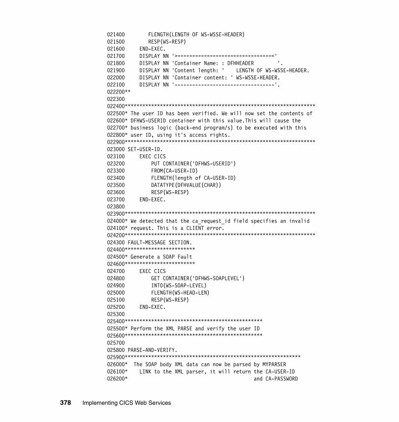
021400 FLENGTH(LENGTH OF WS-WSSE-HEADER)021500 RESP(WS-RESP)021600 END-EXEC.021700 DISPLAY NN '>================================<'021800 DISPLAY NN 'Container Name: : DFHHEADER '.021900 DISPLAY NN 'Content length: ' LENGTH OF WS-WSSE-HEADER.022000 DISPLAY NN 'Container content: ' WS-WSSE-HEADER.022100 DISPLAY NN '----------------------------------'.022200**022300022400*****************************************************************022500* The user ID has been verified. We will now set the contents of022600* DFHWS-USERID container with this value.This will cause the022700* business logic (back-end program/s) to be executed with this022800* user ID, using it's access rights.022900*****************************************************************023000 SET-USER-ID.023100 EXEC CICS023200 PUT CONTAINER('DFHWS-USERID')023300 FROM(CA-USER-ID)023400 FLENGTH(length of CA-USER-ID)023500 DATATYPE(DFHVALUE(CHAR))023600 RESP(WS-RESP)023700 END-EXEC.023800023900*****************************************************************024000* We detected that the ca_request_id field specifies an invalid024100* request. This is a CLIENT error.024200*****************************************************************024300 FAULT-MESSAGE SECTION.024400************************024500* Generate a SOAP Fault024600************************024700 EXEC CICS024800 GET CONTAINER('DFHWS-SOAPLEVEL')024900 INTO(WS-SOAP-LEVEL)025000 FLENGTH(WS-HEAD-LEN)025100 RESP(WS-RESP)025200 END-EXEC.025300025400***********************************************025500* Perform the XML PARSE and verify the user ID025600***********************************************025700025800 PARSE-AND-VERIFY.025900************************************************************026000* The SOAP body XML data can now be parsed by MYPARSER026100* LINK to the XML parser, it will return the CA-USER-ID026200* and CA-PASSWORD
378 Implementing CICS Web Services
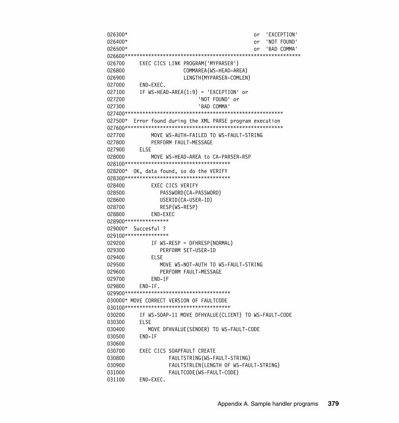
026300* or 'EXCEPTION'026400* or 'NOT FOUND'026500* or 'BAD COMMA'026600************************************************************026700 EXEC CICS LINK PROGRAM('MYPARSER')026800 COMMAREA(WS-HEAD-AREA)026900 LENGTH(MYPARSER-COMLEN)027000 END-EXEC.027100 IF WS-HEAD-AREA(1:9) = 'EXCEPTION' or027200 'NOT FOUND' or027300 'BAD COMMA'027400******************************************************027500* Error found during the XML PARSE program execution027600******************************************************027700 MOVE WS-AUTH-FAILED TO WS-FAULT-STRING027800 PERFORM FAULT-MESSAGE027900 ELSE028000 MOVE WS-HEAD-AREA to CA-PARSER-RSP028100************************************028200* OK, data found, so do the VERIFY028300************************************028400 EXEC CICS VERIFY028500 PASSWORD(CA-PASSWORD)028600 USERID(CA-USER-ID)028700 RESP(WS-RESP)028800 END-EXEC028900***************029000* Succesful ?029100***************029200 IF WS-RESP = DFHRESP(NORMAL)029300 PERFORM SET-USER-ID029400 ELSE029500 MOVE WS-NOT-AUTH TO WS-FAULT-STRING029600 PERFORM FAULT-MESSAGE029700 END-IF029800 END-IF.029900************************************030000* MOVE CORRECT VERSION OF FAULTCODE030100************************************030200 IF WS-SOAP-11 MOVE DFHVALUE(CLIENT) TO WS-FAULT-CODE030300 ELSE030400 MOVE DFHVALUE(SENDER) TO WS-FAULT-CODE030500 END-IF030600030700 EXEC CICS SOAPFAULT CREATE030800 FAULTSTRING(WS-FAULT-STRING)030900 FAULTSTRLEN(LENGTH OF WS-FAULT-STRING)031000 FAULTCODE(WS-FAULT-CODE)031100 END-EXEC.
Appendix A. Sample handler programs 379
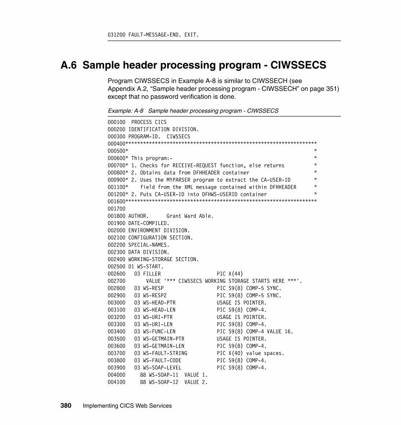
031200 FAULT-MESSAGE-END. EXIT.
A.6 Sample header processing program - CIWSSECSProgram CIWSSECS in Example A-8 is similar to CIWSSECH (see Appendix A.2, “Sample header processing program - CIWSSECH” on page 351) except that no password verification is done.
Example: A-8 Sample header processing program - CIWSSECS
000100 PROCESS CICS000200 IDENTIFICATION DIVISION.000300 PROGRAM-ID. CIWSSECS000400*****************************************************************000500* *000600* This program:- *000700* 1. Checks for RECEIVE-REQUEST function, else returns *000800* 2. Obtains data from DFHHEADER container *000900* 2. Uses the MYPARSER program to extract the CA-USER-ID *001100* field from the XML message contained within DFHHEADER *001200* 2. Puts CA-USER-ID into DFHWS-USERID container *001600*****************************************************************001700001800 AUTHOR. Grant Ward Able.001900 DATE-COMPILED.002000 ENVIRONMENT DIVISION.002100 CONFIGURATION SECTION.002200 SPECIAL-NAMES.002300 DATA DIVISION.002400 WORKING-STORAGE SECTION.002500 01 WS-START.002600 03 FILLER PIC X(44)002700 VALUE '*** CIWSSECS WORKING STORAGE STARTS HERE ***'.002800 03 WS-RESP PIC S9(8) COMP-5 SYNC.002900 03 WS-RESP2 PIC S9(8) COMP-5 SYNC.003000 03 WS-HEAD-PTR USAGE IS POINTER.003100 03 WS-HEAD-LEN PIC S9(8) COMP-4.003200 03 WS-URI-PTR USAGE IS POINTER.003300 03 WS-URI-LEN PIC S9(8) COMP-4.003400 03 WS-FUNC-LEN PIC S9(8) COMP-4 VALUE 16.003500 03 WS-GETMAIN-PTR USAGE IS POINTER.003600 03 WS-GETMAIN-LEN PIC S9(8) COMP-4.003700 03 WS-FAULT-STRING PIC X(40) value spaces.003800 03 WS-FAULT-CODE PIC S9(8) COMP-4.003900 03 WS-SOAP-LEVEL PIC S9(8) COMP-4.004000 88 WS-SOAP-11 VALUE 1.004100 88 WS-SOAP-12 VALUE 2.
380 Implementing CICS Web Services
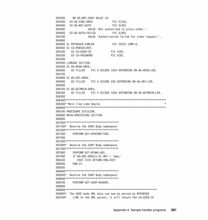
004200 88 WS-NOT-SOAP VALUE 10.004300 03 WS-FUNC-AREA PIC X(16).004400 03 WS-NOT-AUTH PIC X(40)004500 VALUE 'Not authorized to place order.'.004600 03 WS-AUTH-FAILED PIC X(40)004700 VALUE 'Authorization failed for order request.'.004800004900 01 MYPARSER-COMLEN PIC S9(4) COMP-4.005000 01 CA-PARSER-RSP.005100 03 CA-USER-ID PIC X(8).005200 03 CA-PASSWORD PIC X(8).005300005400 LINKAGE SECTION.005500 01 WS-HEAD-AREA.005600 02 FILLER PIC X OCCURS 1024 DEPENDING ON WS-HEAD-LEN.005700005800 01 WS-URI-AREA.005900 02 FILLER PIC X OCCURS 256 DEPENDING ON WS-URI-LEN.006000006100 01 WS-GETMAIN-AREA.006200 02 FILLER PIC X OCCURS 1024 DEPENDING ON WS-GETMAIN-LEN.006300006400******************************************************************006500* Main line code begins *006600******************************************************************006700 PROCEDURE DIVISION.006800 MAIN-PROCESSING SECTION.006900007000***********************************007100* Receive the SOAP Body namespace007200***********************************007300 PERFORM GET-DFHFUNCTION.007400007500***********************************007600* Receive the SOAP Body namespace007700***********************************007800 PERFORM GET-DFHWS-URI.007900 IF WS-URI-AREA(1:4) NOT = 'wmq:'008100 EXEC CICS RETURN END-EXEC008200 END-IF.008300008400***********************************008500* Receive the SOAP Body namespace008600***********************************008700 PERFORM GET-SOAP-HEADER.008800008900************************************************************009000* The SOAP body XML data can now be parsed by MYPARSER009100* LINK to the XML parser, it will return the CA-USER-ID
Appendix A. Sample handler programs 381
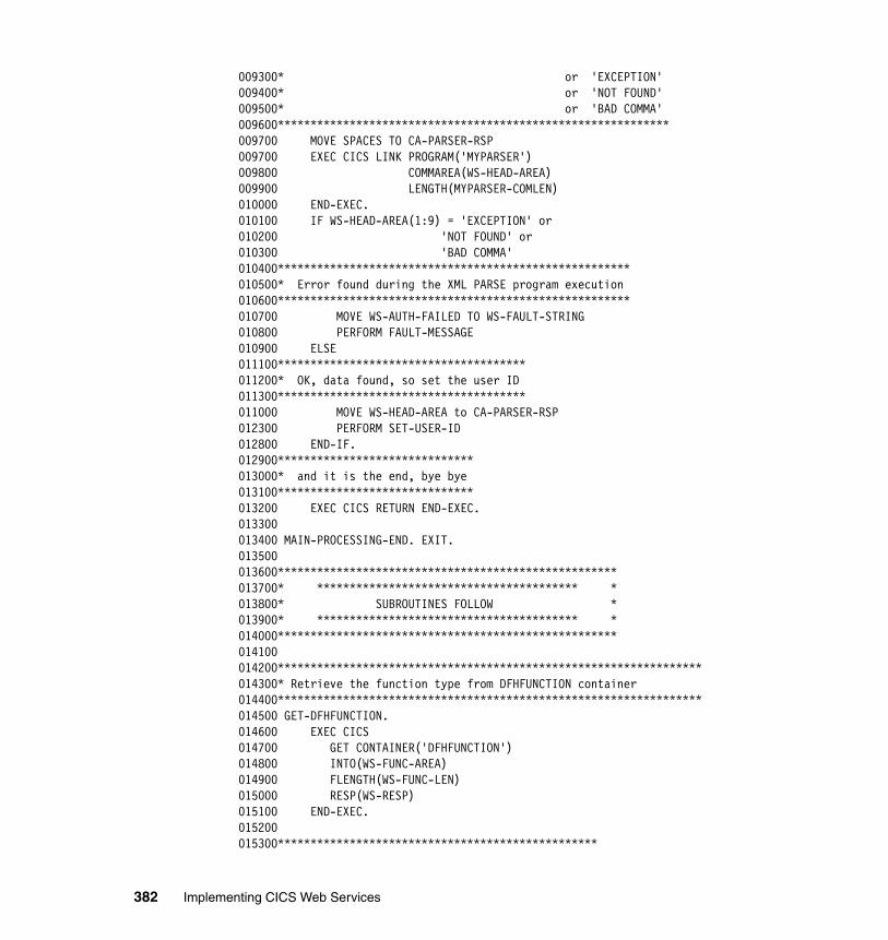
009300* or 'EXCEPTION'009400* or 'NOT FOUND'009500* or 'BAD COMMA'009600************************************************************009700 MOVE SPACES TO CA-PARSER-RSP009700 EXEC CICS LINK PROGRAM('MYPARSER')009800 COMMAREA(WS-HEAD-AREA)009900 LENGTH(MYPARSER-COMLEN)010000 END-EXEC.010100 IF WS-HEAD-AREA(1:9) = 'EXCEPTION' or010200 'NOT FOUND' or010300 'BAD COMMA'010400******************************************************010500* Error found during the XML PARSE program execution010600******************************************************010700 MOVE WS-AUTH-FAILED TO WS-FAULT-STRING010800 PERFORM FAULT-MESSAGE010900 ELSE011100**************************************011200* OK, data found, so set the user ID011300**************************************011000 MOVE WS-HEAD-AREA to CA-PARSER-RSP012300 PERFORM SET-USER-ID012800 END-IF.012900******************************013000* and it is the end, bye bye013100******************************013200 EXEC CICS RETURN END-EXEC.013300013400 MAIN-PROCESSING-END. EXIT.013500013600****************************************************013700* **************************************** *013800* SUBROUTINES FOLLOW *013900* **************************************** *014000****************************************************014100014200*****************************************************************014300* Retrieve the function type from DFHFUNCTION container014400*****************************************************************014500 GET-DFHFUNCTION.014600 EXEC CICS014700 GET CONTAINER('DFHFUNCTION')014800 INTO(WS-FUNC-AREA)014900 FLENGTH(WS-FUNC-LEN)015000 RESP(WS-RESP)015100 END-EXEC.015200015300*************************************************
382 Implementing CICS Web Services
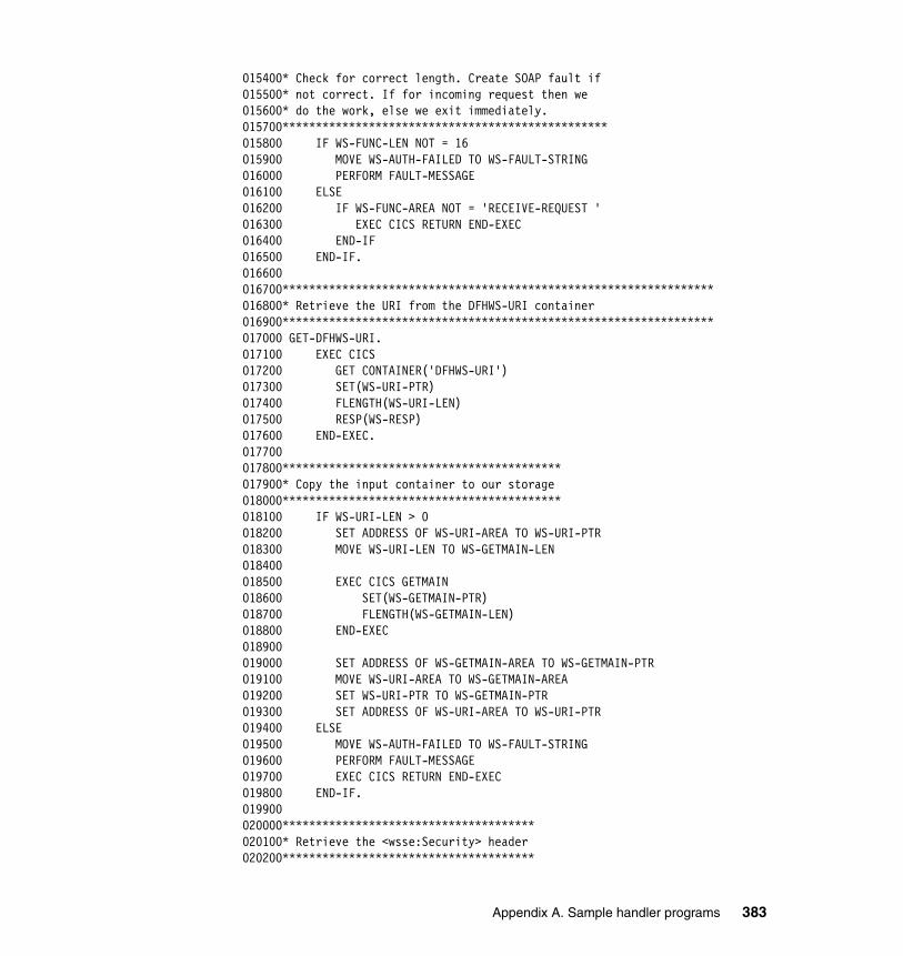
015400* Check for correct length. Create SOAP fault if015500* not correct. If for incoming request then we015600* do the work, else we exit immediately.015700*************************************************015800 IF WS-FUNC-LEN NOT = 16015900 MOVE WS-AUTH-FAILED TO WS-FAULT-STRING016000 PERFORM FAULT-MESSAGE016100 ELSE016200 IF WS-FUNC-AREA NOT = 'RECEIVE-REQUEST '016300 EXEC CICS RETURN END-EXEC016400 END-IF016500 END-IF.016600016700*****************************************************************016800* Retrieve the URI from the DFHWS-URI container016900*****************************************************************017000 GET-DFHWS-URI.017100 EXEC CICS017200 GET CONTAINER('DFHWS-URI')017300 SET(WS-URI-PTR)017400 FLENGTH(WS-URI-LEN)017500 RESP(WS-RESP)017600 END-EXEC.017700017800******************************************017900* Copy the input container to our storage018000******************************************018100 IF WS-URI-LEN > 0018200 SET ADDRESS OF WS-URI-AREA TO WS-URI-PTR018300 MOVE WS-URI-LEN TO WS-GETMAIN-LEN018400018500 EXEC CICS GETMAIN018600 SET(WS-GETMAIN-PTR)018700 FLENGTH(WS-GETMAIN-LEN)018800 END-EXEC018900019000 SET ADDRESS OF WS-GETMAIN-AREA TO WS-GETMAIN-PTR019100 MOVE WS-URI-AREA TO WS-GETMAIN-AREA019200 SET WS-URI-PTR TO WS-GETMAIN-PTR019300 SET ADDRESS OF WS-URI-AREA TO WS-URI-PTR019400 ELSE019500 MOVE WS-AUTH-FAILED TO WS-FAULT-STRING019600 PERFORM FAULT-MESSAGE019700 EXEC CICS RETURN END-EXEC019800 END-IF.019900020000**************************************020100* Retrieve the <wsse:Security> header020200**************************************
Appendix A. Sample handler programs 383
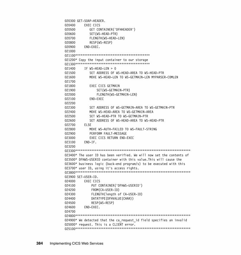
020300 GET-SOAP-HEADER.020400 EXEC CICS020500 GET CONTAINER('DFHHEADER')020600 SET(WS-HEAD-PTR)020700 FLENGTH(WS-HEAD-LEN)020800 RESP(WS-RESP)020900 END-EXEC.021000021100******************************************021200* Copy the input container to our storage021300******************************************021400 IF WS-HEAD-LEN > 0021500 SET ADDRESS OF WS-HEAD-AREA TO WS-HEAD-PTR021600 MOVE WS-HEAD-LEN TO WS-GETMAIN-LEN MYPARSER-COMLEN021700021800 EXEC CICS GETMAIN021900 SET(WS-GETMAIN-PTR)022000 FLENGTH(WS-GETMAIN-LEN)022100 END-EXEC022200022300 SET ADDRESS OF WS-GETMAIN-AREA TO WS-GETMAIN-PTR022400 MOVE WS-HEAD-AREA TO WS-GETMAIN-AREA022500 SET WS-HEAD-PTR TO WS-GETMAIN-PTR022600 SET ADDRESS OF WS-HEAD-AREA TO WS-HEAD-PTR022700 ELSE022800 MOVE WS-AUTH-FAILED TO WS-FAULT-STRING022900 PERFORM FAULT-MESSAGE023000 EXEC CICS RETURN END-EXEC023100 END-IF.023200023300*****************************************************************023400* The user ID has been verified. We will now set the contents of023500* DFHWS-USERID container with this value.This will cause the023600* business logic (back-end program/s) to be executed with this023700* user ID, using it's access rights.023800*****************************************************************023900 SET-USER-ID.024000 EXEC CICS024100 PUT CONTAINER('DFHWS-USERID')024200 FROM(CA-USER-ID)024300 FLENGTH(length of CA-USER-ID)024400 DATATYPE(DFHVALUE(CHAR))024500 RESP(WS-RESP)024600 END-EXEC.024700024800*****************************************************************024900* We detected that the ca_request_id field specifies an invalid025000* request. This is a CLIENT error.025100*****************************************************************
384 Implementing CICS Web Services
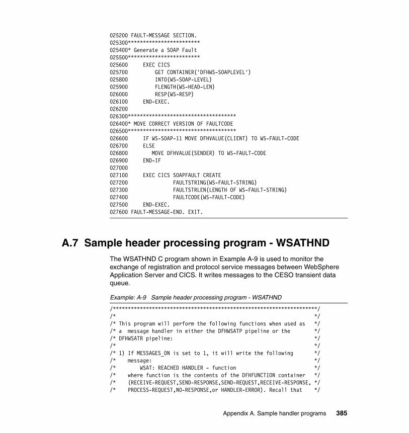
025200 FAULT-MESSAGE SECTION.025300************************025400* Generate a SOAP Fault025500************************025600 EXEC CICS025700 GET CONTAINER('DFHWS-SOAPLEVEL')025800 INTO(WS-SOAP-LEVEL)025900 FLENGTH(WS-HEAD-LEN)026000 RESP(WS-RESP)026100 END-EXEC.026200026300************************************026400* MOVE CORRECT VERSION OF FAULTCODE026500************************************026600 IF WS-SOAP-11 MOVE DFHVALUE(CLIENT) TO WS-FAULT-CODE026700 ELSE026800 MOVE DFHVALUE(SENDER) TO WS-FAULT-CODE026900 END-IF027000027100 EXEC CICS SOAPFAULT CREATE027200 FAULTSTRING(WS-FAULT-STRING)027300 FAULTSTRLEN(LENGTH OF WS-FAULT-STRING)027400 FAULTCODE(WS-FAULT-CODE)027500 END-EXEC.027600 FAULT-MESSAGE-END. EXIT.
A.7 Sample header processing program - WSATHNDThe WSATHND C program shown in Example A-9 is used to monitor the exchange of registration and protocol service messages between WebSphere Application Server and CICS. It writes messages to the CESO transient data queue.
Example: A-9 Sample header processing program - WSATHND
/********************************************************************//* *//* This program will perform the following functions when used as *//* a message handler in either the DFHWSATP pipeline or the *//* DFHWSATR pipeline: *//* *//* 1) If MESSAGES_ON is set to 1, it will write the following *//* message: *//* WSAT: REACHED HANDLER - function *//* where function is the contents of the DFHFUNCTION container *//* (RECEIVE-REQUEST,SEND-RESPONSE,SEND-REQUEST,RECEIVE-RESPONSE, *//* PROCESS-REQUEST,NO-RESPONSE,or HANDLER-ERROR). Recall that */
Appendix A. Sample handler programs 385
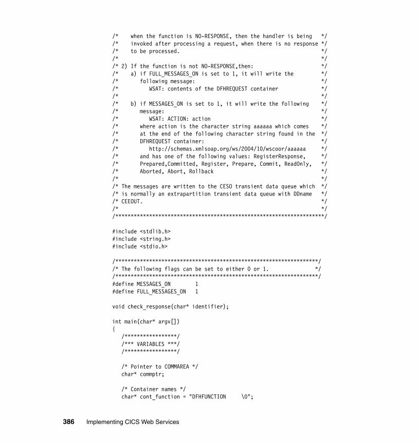
/* when the function is NO-RESPONSE, then the handler is being *//* invoked after processing a request, when there is no response *//* to be processed. *//* *//* 2) If the function is not NO-RESPONSE,then: *//* a) if FULL_MESSAGES_ON is set to 1, it will write the *//* following message: *//* WSAT: contents of the DFHREQUEST container *//* *//* b) if MESSAGES_ON is set to 1, it will write the following *//* message: *//* WSAT: ACTION: action *//* where action is the character string aaaaaa which comes *//* at the end of the following character string found in the *//* DFHREQUEST container: *//* http://schemas.xmlsoap.org/ws/2004/10/wscoor/aaaaaa *//* and has one of the following values: RegisterResponse, *//* Prepared,Committed, Register, Prepare, Commit, ReadOnly, *//* Aborted, Abort, Rollback *//* *//* The messages are written to the CESO transient data queue which *//* is normally an extrapartition transient data queue with DDname *//* CEEOUT. *//* *//********************************************************************/
#include <stdlib.h>#include <string.h>#include <stdio.h>
/******************************************************************//* The following flags can be set to either 0 or 1. *//******************************************************************/#define MESSAGES_ON 1#define FULL_MESSAGES_ON 1
void check_response(char* identifier);
int main(char* argv[]){ /*****************/ /*** VARIABLES ***/ /*****************/
/* Pointer to COMMAREA */ char* commptr;
/* Container names */ char* cont_function = "DFHFUNCTION \0";
386 Implementing CICS Web Services
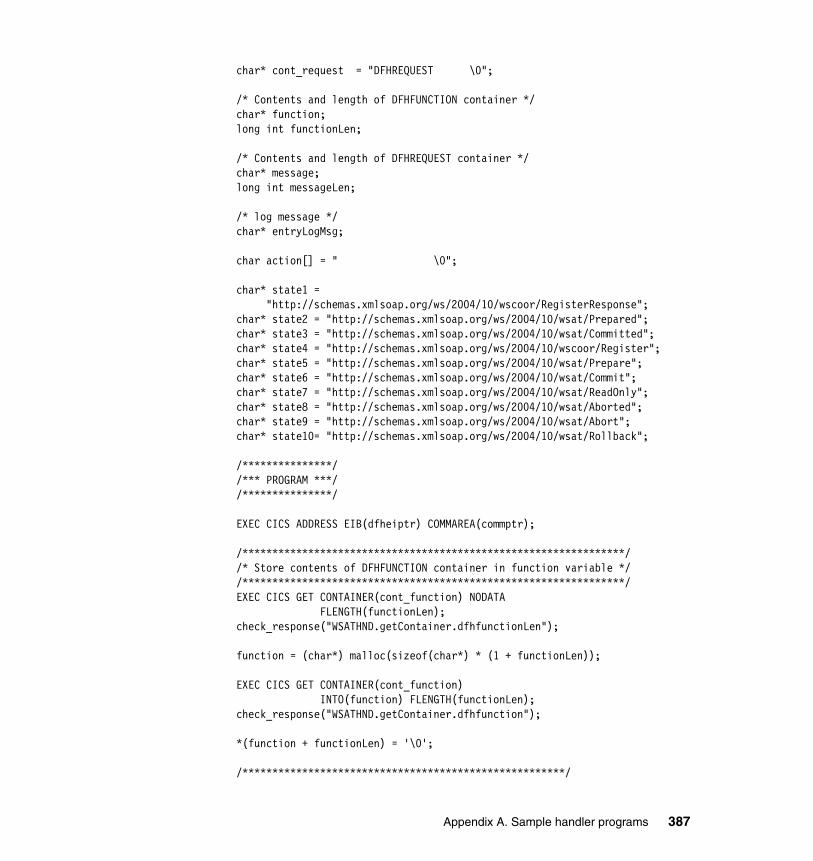
char* cont_request = "DFHREQUEST \0";
/* Contents and length of DFHFUNCTION container */ char* function; long int functionLen;
/* Contents and length of DFHREQUEST container */ char* message; long int messageLen;
/* log message */ char* entryLogMsg;
char action[] = " \0";
char* state1 = "http://schemas.xmlsoap.org/ws/2004/10/wscoor/RegisterResponse"; char* state2 = "http://schemas.xmlsoap.org/ws/2004/10/wsat/Prepared"; char* state3 = "http://schemas.xmlsoap.org/ws/2004/10/wsat/Committed"; char* state4 = "http://schemas.xmlsoap.org/ws/2004/10/wscoor/Register"; char* state5 = "http://schemas.xmlsoap.org/ws/2004/10/wsat/Prepare"; char* state6 = "http://schemas.xmlsoap.org/ws/2004/10/wsat/Commit"; char* state7 = "http://schemas.xmlsoap.org/ws/2004/10/wsat/ReadOnly"; char* state8 = "http://schemas.xmlsoap.org/ws/2004/10/wsat/Aborted"; char* state9 = "http://schemas.xmlsoap.org/ws/2004/10/wsat/Abort"; char* state10= "http://schemas.xmlsoap.org/ws/2004/10/wsat/Rollback";
/***************/ /*** PROGRAM ***/ /***************/
EXEC CICS ADDRESS EIB(dfheiptr) COMMAREA(commptr);
/****************************************************************/ /* Store contents of DFHFUNCTION container in function variable */ /****************************************************************/ EXEC CICS GET CONTAINER(cont_function) NODATA FLENGTH(functionLen); check_response("WSATHND.getContainer.dfhfunctionLen");
function = (char*) malloc(sizeof(char*) * (1 + functionLen));
EXEC CICS GET CONTAINER(cont_function) INTO(function) FLENGTH(functionLen); check_response("WSATHND.getContainer.dfhfunction");
*(function + functionLen) = '\0';
/******************************************************/
Appendix A. Sample handler programs 387
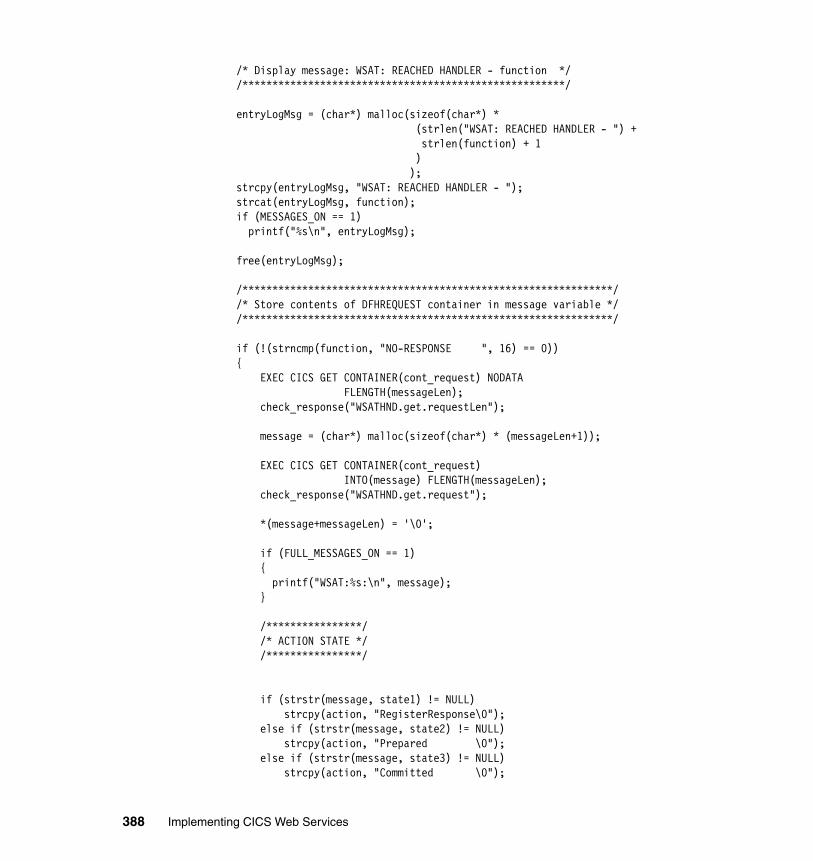
/* Display message: WSAT: REACHED HANDLER - function */ /******************************************************/
entryLogMsg = (char*) malloc(sizeof(char*) * (strlen("WSAT: REACHED HANDLER - ") + strlen(function) + 1 ) ); strcpy(entryLogMsg, "WSAT: REACHED HANDLER - "); strcat(entryLogMsg, function); if (MESSAGES_ON == 1) printf("%s\n", entryLogMsg);
free(entryLogMsg);
/**************************************************************/ /* Store contents of DFHREQUEST container in message variable */ /**************************************************************/
if (!(strncmp(function, "NO-RESPONSE ", 16) == 0)) { EXEC CICS GET CONTAINER(cont_request) NODATA FLENGTH(messageLen); check_response("WSATHND.get.requestLen");
message = (char*) malloc(sizeof(char*) * (messageLen+1));
EXEC CICS GET CONTAINER(cont_request) INTO(message) FLENGTH(messageLen); check_response("WSATHND.get.request");
*(message+messageLen) = '\0';
if (FULL_MESSAGES_ON == 1) { printf("WSAT:%s:\n", message); }
/****************/ /* ACTION STATE */ /****************/
if (strstr(message, state1) != NULL) strcpy(action, "RegisterResponse\0"); else if (strstr(message, state2) != NULL) strcpy(action, "Prepared \0"); else if (strstr(message, state3) != NULL) strcpy(action, "Committed \0");
388 Implementing CICS Web Services
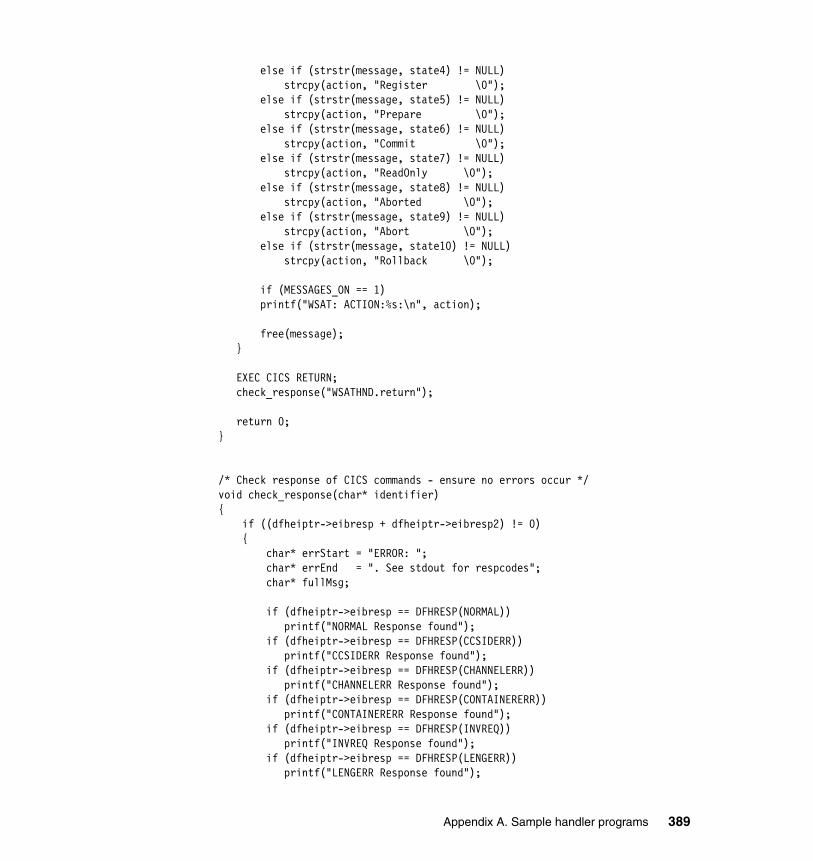
else if (strstr(message, state4) != NULL) strcpy(action, "Register \0"); else if (strstr(message, state5) != NULL) strcpy(action, "Prepare \0"); else if (strstr(message, state6) != NULL) strcpy(action, "Commit \0"); else if (strstr(message, state7) != NULL) strcpy(action, "ReadOnly \0"); else if (strstr(message, state8) != NULL) strcpy(action, "Aborted \0"); else if (strstr(message, state9) != NULL) strcpy(action, "Abort \0"); else if (strstr(message, state10) != NULL) strcpy(action, "Rollback \0");
if (MESSAGES_ON == 1) printf("WSAT: ACTION:%s:\n", action);
free(message); }
EXEC CICS RETURN; check_response("WSATHND.return");
return 0;}
/* Check response of CICS commands - ensure no errors occur */void check_response(char* identifier){ if ((dfheiptr->eibresp + dfheiptr->eibresp2) != 0) { char* errStart = "ERROR: "; char* errEnd = ". See stdout for respcodes"; char* fullMsg;
if (dfheiptr->eibresp == DFHRESP(NORMAL)) printf("NORMAL Response found"); if (dfheiptr->eibresp == DFHRESP(CCSIDERR)) printf("CCSIDERR Response found"); if (dfheiptr->eibresp == DFHRESP(CHANNELERR)) printf("CHANNELERR Response found"); if (dfheiptr->eibresp == DFHRESP(CONTAINERERR)) printf("CONTAINERERR Response found"); if (dfheiptr->eibresp == DFHRESP(INVREQ)) printf("INVREQ Response found"); if (dfheiptr->eibresp == DFHRESP(LENGERR)) printf("LENGERR Response found");
Appendix A. Sample handler programs 389
printf("Error: %s\n", identifier); printf("Error resp1: %d\n", dfheiptr->eibresp); printf("Error resp2: %d\n", dfheiptr->eibresp2);
fullMsg = (char*) malloc((strlen(errStart) + strlen(identifier) + strlen(errEnd) + 1) * sizeof(char*));
strcpy(fullMsg, errStart); strcat(fullMsg, identifier); strcat(fullMsg, errEnd);
EXEC CICS SEND TEXT FROM(fullMsg) LENGTH(strlen(fullMsg));
free(fullMsg);
exit; }}
390 Implementing CICS Web Services
Appendix B. Additional material
This redbook refers to additional material that can be downloaded from the Internet as described here.
Locating the Web materialThe Web material associated with this redbook is available in softcopy on the Internet from the IBM Redbooks Web server. Point your Web browser to:
ftp://www.redbooks.ibm.com/redbooks/SG247206
Alternatively, you can go to the IBM Redbooks Web site at:
ibm.com/redbooks
Select the Additional materials and open the directory that corresponds with the redbook form number, SG24-7206.
Using the Web materialThe additional Web material that accompanies this redbook includes the following files:
File name DescriptionSG247206.zip Zipped Code Samples
B
© Copyright IBM Corp. 2006. All rights reserved. 391
System requirements for downloading the Web materialThe following system configuration is recommended:
Hard disk space: 1MB minimumOperating System: Windows 2000 or Windows XPProcessor: Intel® Pentium®Memory: 128MB
How to use the materialCreate a subdirectory (folder) on your workstation, and unzip the contents of the Web material zip file into this folder.
The additional Web material (SG247206.zip) that accompanies this redbook contains the following directory structure:
� A cics directory containing the following CICS pipeline handler program source code:
– CIWSMSGH.txt (as introduced in Chapter 3)
– SNIFFER.txt (as introduced in Chapter 3)
– CIWSSECH.txt, CIWSSECR.txt, CIWSSECS.txt and MYPARSER.txt (as introduced in Chapter 7)
– WSATHND.txt (as introduced in Chapter 10)
For further details on these applications, refer to Appendix A, “Sample handler programs” on page 345.
� An ears directory containing the following EAR files for our sample Web service applications.
Table B-1 shows the sample J2EE applications we used when testing the scenarios.
Table B-1 Sample J2EE applications
EAR files Description
Catalog.ear Catalog manager service requester application, see “Installing the service requester” on page 87.
dispatchOrder.ear Catalog manager dispathOrder service provider application, see “Installing the service provider” on page 99.
392 Implementing CICS Web Services
� A config directory containing the pipeline configuration files for our sample Web service applications.
Table B-2 shows the sample pipeline configuration files we used during test of the scenarios.
Table B-2 Sample pipeline configuration files
CatalogSec.ear Catalog manager service requester application with no security enabled, see , see “Editing the client configuration” on page 190.
CatalogSec_WS-Security.ear Catalog manager service requester application with WS-security enabled, see “Editing the client configuration” on page 190.
CatalogSec_WS-Security_HTTPS.ear Catalog manager service requester application with WS-security and HTTPS enabled, see “Enabling the service requester to use HTTPS” on page 210.
CatalogAtomic.ear Catalog manager service requester application with WS-AT enabled, see “Change the deployment descriptor” on page 296.
DispatchOrderAtomic.ear Catalog manager service provider application with WS-AT enabled, see “Creating DispatchOrderAtomic and the ITSO.DISPATCH table” on page 332.
Configuration file Description
ITSO_7206_basicsoap12provider.xml Service provider sample as supplied by CICS, with addition of a message handler program to set the transaction ID. See Example 3-4 on page 80.
EAR files Description
Appendix B. Additional material 393
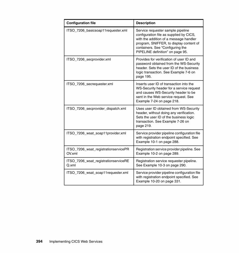
ITSO_7206_basicsoap11requester.xml Service requester sample pipeline configuration file as supplied by CICS, with the addition of a message handler program, SNIFFER, to display content of containers. See “Configuring the PIPELINE definition” on page 95.
ITSO_7206_secprovider.xml Provides for verification of user ID and password obtained from the WS-Security header. Sets the user ID of the business logic transaction. See Example 7-6 on page 195.
ITSO_7206_secrequester.xml Inserts user ID of transaction into the WS-Security header for a service request and causes WS-Security header to be sent in the Web service request. See Example 7-24 on page 218.
ITSO_7206_secprovider_dispatch.xml Uses user ID obtained from WS-Security header, without doing any verification. Sets the user ID of the business logic transaction. See Example 7-26 on page 219.
ITSO_7206_wsat_soap11provider.xml Service provider pipeline configuration file with registration endpoint specified. See Example 10-1 on page 288.
ITSO_7206_wsat_registrationservicePROV.xml
Registration service provider pipeline. See Example 10-2 on page 289.
ITSO_7206_wsat_registrationserviceREQ.xml
Registration service requester pipeline. See Example 10-3 on page 290.
ITSO_7206_wsat_soap11requester.xml Service provider pipeline configuration file with registration endpoint specified. See Example 10-20 on page 331.
Configuration file Description
394 Implementing CICS Web Services
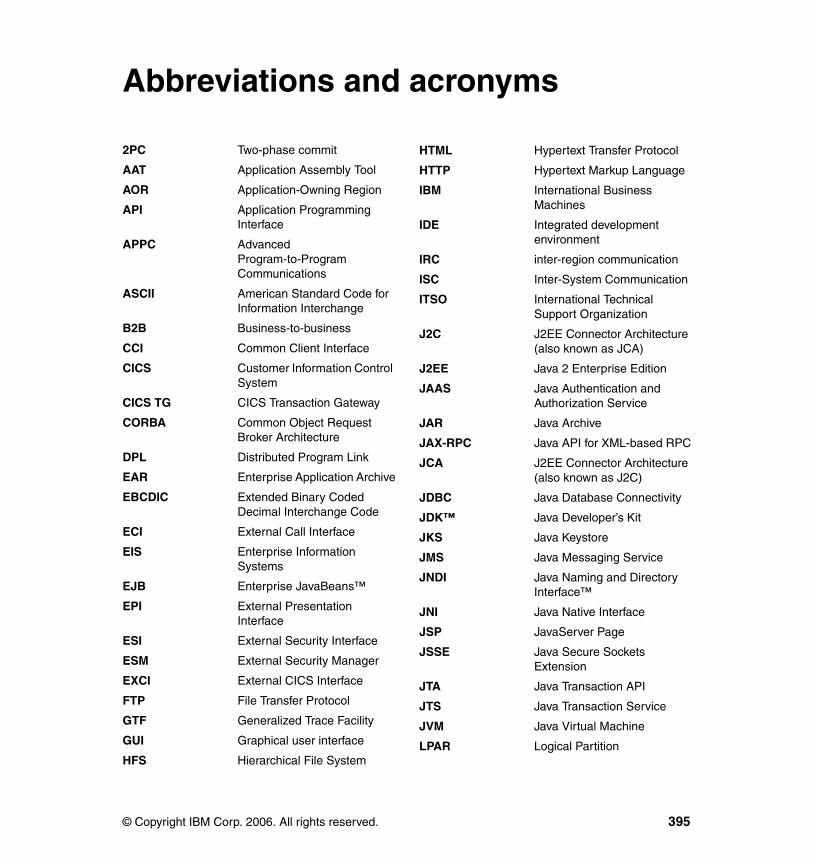
acronyms
2PC Two-phase commitAAT Application Assembly Tool
AOR Application-Owning Region
API Application Programming Interface
APPC Advanced Program-to-Program Communications
ASCII American Standard Code for Information Interchange
B2B Business-to-business
CCI Common Client Interface
CICS Customer Information Control System
CICS TG CICS Transaction Gateway
CORBA Common Object Request Broker Architecture
DPL Distributed Program Link
EAR Enterprise Application Archive
EBCDIC Extended Binary Coded Decimal Interchange Code
ECI External Call Interface
EIS Enterprise Information Systems
EJB Enterprise JavaBeans™
EPI External Presentation Interface
ESI External Security Interface
ESM External Security Manager
EXCI External CICS Interface
FTP File Transfer Protocol
GTF Generalized Trace Facility
GUI Graphical user interface
HFS Hierarchical File System
Abbreviations and
© Copyright IBM Corp. 2006. All rights reserved.
HTML Hypertext Transfer Protocol
HTTP Hypertext Markup Language
IBM International Business Machines
IDE Integrated development environment
IRC inter-region communication
ISC Inter-System Communication
ITSO International Technical Support Organization
J2C J2EE Connector Architecture (also known as JCA)
J2EE Java 2 Enterprise Edition
JAAS Java Authentication and Authorization Service
JAR Java Archive
JAX-RPC Java API for XML-based RPC
JCA J2EE Connector Architecture (also known as J2C)
JDBC Java Database Connectivity
JDK™ Java Developer’s Kit
JKS Java Keystore
JMS Java Messaging Service
JNDI Java Naming and Directory Interface™
JNI Java Native Interface
JSP JavaServer Page
JSSE Java Secure Sockets Extension
JTA Java Transaction API
JTS Java Transaction Service
JVM Java Virtual Machine
LPAR Logical Partition
395
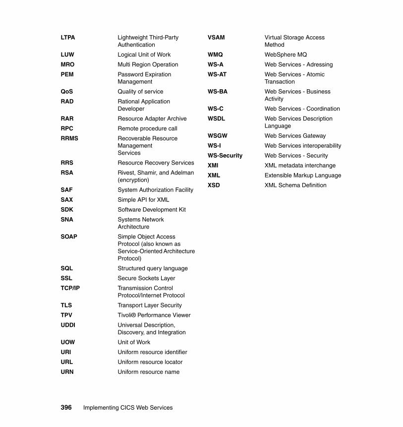
LTPA Lightweight Third-Party Authentication
LUW Logical Unit of Work
MRO Multi Region Operation
PEM Password Expiration Management
QoS Quality of service
RAD Rational Application Developer
RAR Resource Adapter Archive
RPC Remote procedure call
RRMS Recoverable Resource ManagementServices
RRS Resource Recovery Services
RSA Rivest, Shamir, and Adelman (encryption)
SAF System Authorization Facility
SAX Simple API for XML
SDK Software Development Kit
SNA Systems Network Architecture
SOAP Simple Object Access Protocol (also known as Service-Oriented Architecture Protocol)
SQL Structured query language
SSL Secure Sockets Layer
TCP/IP Transmission Control Protocol/Internet Protocol
TLS Transport Layer Security
TPV Tivoli® Performance Viewer
UDDI Universal Description, Discovery, and Integration
UOW Unit of Work
URI Uniform resource identifier
URL Uniform resource locator
URN Uniform resource name
VSAM Virtual Storage Access Method
WMQ WebSphere MQ
WS-A Web Services - Adressing
WS-AT Web Services - Atomic Transaction
WS-BA Web Services - Business Activity
WS-C Web Services - Coordination
WSDL Web Services Description Language
WSGW Web Services Gateway
WS-I Web Services interoperability
WS-Security Web Services - Security
XMI XML metadata interchange
XML Extensible Markup Language
XSD XML Schema Definition
396 Implementing CICS Web Services
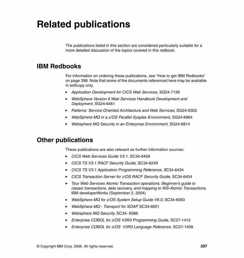
Related publications
The publications listed in this section are considered particularly suitable for a more detailed discussion of the topics covered in this redbook.
IBM RedbooksFor information on ordering these publications, see “How to get IBM Redbooks” on page 398. Note that some of the documents referenced here may be available in softcopy only.
� Application Development for CICS Web Services, SG24-7126
� WebSphere Version 6 Web Services Handbook Development and Deployment, SG24-6461
� Patterns: Service-Oriented Architecture and Web Services, SG24-6303
� WebSphere MQ in a z/OS Parallel Sysplex Environment, SG24-6864
� Websphere MQ Security in an Enterprise Environment, SG24-6814
Other publicationsThese publications are also relevant as further information sources:
� CICS Web Services Guide V3.1, SC34-6458
� CICS TS V3.1 RACF Security Guide, SC34-6249
� CICS TS V3.1 Application Programming Reference, SC34-6434
� CICS Transaction Server for z/OS RACF Security Guide, SC34-6454
� Tour Web Services Atomic Transaction operations: Beginner’s guide to classic transactions, data recovery, and mapping to WS-Atomic Transactions, IBM developerWorks (September 2, 2004)
� WebSphere MQ for z/OS System Setup Guide V6.0, SC34-6583
� WebSphere MQ - Transport for SOAP, SC34-6651
� Websphere MQ Security, SC34- 6588
� Enterprise COBOL for z/OS V3R3 Programming Guide, SC27-1412
� Enterprise COBOL for z/OS V3R3 Language Reference, SC27-1408
© Copyright IBM Corp. 2006. All rights reserved. 397
Online resourcesThese Web sites and URLs are also relevant as further information sources:
� CICS library
http://www.ibm.com/software/htp/cics/library/
� WebSphere Application Server library
http://www.ibm.com/software/webservers/appserv/was/library/index.html
How to get IBM RedbooksYou can search for, view, or download Redbooks, Redpapers, Hints and Tips, draft publications and Additional materials, as well as order hardcopy Redbooks or CD-ROMs, at this Web site:
ibm.com/redbooks
Help from IBMIBM Support and downloads
ibm.com/support
IBM Global Services
ibm.com/services
398 Implementing CICS Web Services
Index
AAPARs
PK10849 285PK16509 283PK20393 113
AtomicClient 285–286, 291, 307
Bbasic authentication
sample 192bus
see service integration bus
CC 34C++ 34catalog manager application 67
configuration transaction, ECFG 97, 122, 331testing 90, 100, 124, 145
Catalog.ear 87, 392CatalogAtomic.ear 296, 393CatalogSec.ear 190, 393CatalogSec_WS-Security.ear 195, 393CatalogSec_WS-Security_HTTPS.ear 211, 393channels 59CICS
service provider 37preparation 38using HTTP 76–77using WMQ 116
service requester 41local optimization 45preparation 42timeout considerations 96using HTTP 94–95using WMQ 121
Web services assistant 34, 62DFHLS2WS 63DFHWS2LS 64
Web services support 33catalog manager application 67development tools 61
© Copyright IBM Corp. 2006. All rights reserved.
high availability 101, 126overview 34problem determination 104resources 47resources checklist 55
CICS default user ID 156CICS region user ID 156CIWSMSGH 80, 93, 118, 346CIWSSECH 195–197, 351CIWSSECR 217, 373CIWSSECS 219, 380COBOL 34code page conversion 77containers 59
context container 59control container 59header container 60user container 60
CoordinationContext 246elements 314
Address 315CoordinationType 315Expires 314Identifier 314ReferenceProperties 315RegistrationService 315
example 313sample created by CICS 248sample created by WebSphere 249
CPIH 41, 93CPIL 116cryptography 154
public key 154shared key 155
Ddefault user ID, CICS 156development tools 61DFH$RING 205DFHLS2WS 63DFHPIRS 275DFHPISN1, message handler module 266, 286DFHRSURI, URIMAP resource 272
399
DFHWS2LS 64DFHWSATH, header processing program 266, 273–275, 286DFHWSATP, provider pipeline 267–268DFHWSATR, requester pipeline 267
PIPELINE definition 270DFHWSATX, message handler 267, 270digital signature 169dispatchOrder.ear 99, 392DispatchOrderAtomic.ear 328, 393distributed routing 102–103dynamic program routing 102, 104
EECFG 97, 122, 331electronic data interchange (EDI) 4endpoint
listener 131error handling 16ExampleAppClient.ear 87ExampleAppDispatchOrder 98ExampleAppDispatchOrder.ear 99, 328Extensible Markup Language
see XML
FFTP 9
Ggateway
instance 131configuring 140
service 131, 135configuring 139, 141invoking 147publishing 145testing 145
Hhigh availability
with HTTP 101with WMQ 126
HTTP 36, 73
Iibm-webservices-bnd.xmi 189ibm-webservicesclient-bnd.xmi 189
ibm-webservicesclient-ext.xmi 189ibm-webservices-ext.xmi 189identity assertion 176iKeyMan 207inbound service 131intermediary 173intermediate gateway 173
identity assertion 176
JJ2EE Connector Architecture (JCA) 342Java Transaction API (JTA) 278JAX-RPC
handler 130–131JMS 9
Kkey ring
creating 204keystore 207
Mmediation 130–131message handler 80, 118
introduction 57SOAP message handlers 57
mustUnderstand 14, 195MYPARSER 198, 368
NNamespaces 12
Ooutbound service 131
PPIPELINE 49
attributesCONFIGFILE 50SHELF 50WSDIR 49
defining 83, 95, 119pipeline
configuration file 51customizing 80
pipeline alias transaction 48, 57, 93
400 Implementing CICS Web Services
PL/I 34Port definition 29protocol transformation 132
RRational Application Developer 172Redbooks Web site 398
Contact us xvRequestStream 277RPC 17
style 30RSA (Rivest, Shamir, and Adelman) 154
Ssecurity
authentication 153authorization 154basic authentication
see basic authenticationconfidentiality 154HTTP 157identification 153integrity 154SOAP message 153, 187
see WS-SecuritySSL/TLS 158transport-level 153, 157
comparison with SOAP message security 172
WMQ 162, 220testing 221
servicebroker 5gateway 135
see gateway serviceinbound 131mediation 130outbound 131provider 5requestor 5
service integration bus 129, 139configuration 132securing CICS Web services 174
service requestertimeout considerations 124
service-oriented architecture 3–4characteristics 5
SIT parameters
DFLTUSER 156ENCRYPTION 159KEYRING 160, 211MAXSSLTCBS 160SEC 181SECPRFX 181SSLCACHE 160SSLDELAY 160TCPIP 78XTRAN 181XUSER 181
SMTP 9SNIFFER 106, 286, 357
sample output 365SOA
see service-oriented architectureSOAP 9
1.1 specification 91.2 specification 10binding 30body 15
outbound data conversion 41communication styles 17
document 17RPC 17
encodings 17literal 17SOAP encoding 17
envelope 12–13fault 16Headers 14headers 14MustUnderstand 15namespaces 12Simple Object Access Protocol 9validation in CICS 53
SOAPFAULTcommands
ADD 58CREATE 58
generating a SOAP fault in CICS 201SSL see SSL/TLSSSL/TLS
CICS support for 159creating a key ring 204enabling CICS support 159, 211enabling WebSphere support 206handshake 158testing 212
Index 401
with WMQ 164standards
JAX-RPC 130JCA 342JTA 278SOAP 9UDDI 10WS-Addressing 227WS-Atomic Transaction 227WS-Coordination 227WSDL 10WS-Security 11WS-Transactions 11XML 9
switch profiles 162Sysplex Distributor 102, 128
TTCPIP, SIT parameter 78TCPIPSERVICE 55, 78, 211
attributesAUTHENTICATE 157PORTNUMBER 79PROTOCOL 79SSL 161
TLS see SSL/TLStransactions
atomic 235, 247enabling CICS support 265
business activity 247classic 228–229two phase commit 229
two phase commit (2PC) 229presumed abort 230walkthrough 231with WS-AT 258
UUniversal Description, Discovery, and Integration (UDDI) 10URIMAP 47
attributesUSERID 161
defining 86, 135, 183for serving HFS file 135setting the user ID 182
UsernameToken 170UsernameTokenGenerator 193
WWeb services
definition 7introduction 6properties 7
Web services binding file 55Web Services Description Language
see WSDLWeb Services Gateway 130Web Services Interoperability Organization
see WS-IWEBSERVICE 53
attributesVALIDATION 53WSBIND 53WSDLFILE 53
dynamically installing 85WebSphere
service requesterdeploying 88, 98–99using HTTP 87, 98
WebSphere Application Serveradministrative console 88connection pooling 89
Websphere Developer for zSeries 65WebSphere MQ
see WMQWMQ 112
configuration 114defining queues 115trigger process 116
shared queues 127–128WS Binding page 193WS Extension page 191WS-Addressing 227, 236
CICS Registration Service endpoint 242endpoint reference 237specification 236
WSATHND 290, 385WS-Atomic Transaction (WS-AT) 227, 233, 255
Completion protocol 256daisy chain test scenario 328
testing 335enabling CICS support 266–267enabling WebSphere support 278, 296resynchronization processing 261simple test scenario 287
testing 307specification 246
402 Implementing CICS Web Services
Two-Phase Commit protocol 257Durable 2PC 257Volatile 2PC 257
typical scenario 285walkthrough 233, 260
WS-Business Activityspecification 246
WS-Coordination 227Activation service 244Coordination service 244Protocol services 244Registration service 244specification 243walkthrough 252
WSDL 10, 18binding 19, 27bindings 30definition 24document 19
anatomy 19message 19, 25namespaces 23operation 19, 26port 19, 29port type 19, 26service 19service definition 29SOAP binding 30type 19types 24Web Services Description Language 10
WSGW 130WS-I
basic profile 10introduction 6
WS-Security 164, 187CICS support 166configuration
files 195configuring CICS 195example 166, 195message authentication 166message integrity 168specifications 165test scenario 200typical scenario 165WebSphere client configuration 190WebSphere configuration files 188WebSphere support 170
with WMQ 214
XXML 9XML encryption 170
Index 403

404 Implementing CICS Web Services

(0.5” spine)0.475”<
->0.875”
250 <->
459 pages
Implem
enting CICS Web Services


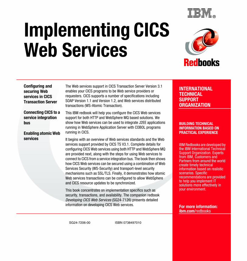
®
SG24-7206-00 ISBN 0738497010
INTERNATIONAL TECHNICALSUPPORTORGANIZATION
BUILDING TECHNICALINFORMATION BASED ONPRACTICAL EXPERIENCE
IBM Redbooks are developed by the IBM International Technical Support Organization. Experts from IBM, Customers and Partners from around the world create timely technical information based on realistic scenarios. Specific recommendations are provided to help you implement IT solutions more effectively in your environment.
For more information:ibm.com/redbooks
Implementing CICS Web Services
Configuring and securing Web services in CICS Transaction Server
Connecting CICS to a service integration bus
Enabling atomic Web services
The Web services support in CICS Transaction Server Version 3.1 enables your CICS programs to be Web service providers or requesters. CICS supports a number of specifications including SOAP Version 1.1 and Version 1.2, and Web services distributed transactions (WS-Atomic Transaction).
This IBM redbook will help you configure the CICS Web services support for both HTTP and WebSphere MQ based solutions. We show how Web services can be used to integrate J2EE applications running in WebSphere Application Server with COBOL programs running in CICS.
It begins with an overview of Web services standards and the Web services support provided by CICS TS V3.1. Complete details for configuring CICS Web services using both HTTP and WebSphere MQ are provided next, along with the steps for using Web services to connect to CICS from a service integration bus. The book then shows how CICS Web services can be secured using a combination of Web Services Security (WS-Security) and transport-level security mechanisms such as SSL/TLS. Finally, it demonstrates how atomic Web services transactions can be configured to allow WebSphere and CICS resource updates to be synchronized.
This book concentrates on implementation specifics such as security, transactions, and availability. The companion redbook Developing CICS Web Services (SG24-7126) presents detailed information on developing CICS Web services.
Back cover