Embed Size (px)
Citation preview

AALTO UNIVERSITY
School of Electrical EngineeringDepartment of Communications and Networking
Jaakko Rantamäki
Implementing Fast Feedback Response in Agile Software Development
Master’s Thesis submitted in partial fulfillment of the requirements for the degree of Master of Science in Technology.
Helsinki, 28th April 2014
Supervisor: Prof. Raimo KantolaInstructor: M.Sc. Teemu Arvonen

i
AALTO UNIVERISTY SCHOOL OF ELECTRICAL ENGINEERING Abstract of the Master’s Thesis
Author: Jaakko Rantamäki
Title: Implementing Fast Feedback Response in Agile Software Development
Date: 28.4.2014 Language: English Number of pages: 10 + 67
Department: Department of Communications and Networking
Professorship: Networking Technology Code: S-38
Supervisor: Prof. Raimo Kantola
Instructor: M.Sc. Teemu Arvonen
Receiving rapid feedback on software functionality in the agile software development methods is important. Traditionally, the test methods for measuring software functionality are based on simulated test tools and test environments. These methods can be time-consuming and do not always reveal problems that may arise when the software is integrated into the target hardware.
In the scope of this research, a study is conducted whether a time efficient fast feedback response test process can be created to ensure the software functionality in target hardware level in initial testing. Thus, making more efficient troubleshooting and fault finding possible by using a fast feedback test in a continuous integration environment. These methods can lead to decreased software development costs and increased software development efficiency.
In this study, a fast feedback test process is created for the software development environment of the Ericsson Mobile Media Gateway. The feasibility of the test process is determined by analyzing the performance of the test process in the development environment. A study on the efficiency of the agile software development methods compared to the waterfall development methods is also conducted by using the Ericsson Mobile Media Gateway development organization as an example.
In conclusion, the initial testing of the fast feedback test indicates that it could be applied to the Ericsson development environment. It is recommended to examine the possibility to use this fast feedback test methodology also in other agile software development projects. There are strong indications that the agile software development methods at Ericsson Mobile Media Gateway development organization are more effective than the previous waterfall development methods.
Keywords: Agile software development methods, continuous integration, rapid software testing, fast feedback, early fault finding, media gateway

ii
AALTO-YLIOPISTO SÄHKÖTEKNIIKAN KORKEAKOULU Diplomityön tiivistelmä
Tekijä: Jaakko Rantamäki
Työn nimi: Nopean vasteen implementointi ketterässä ohjelmistokehityksessä
Päivämäärä: 28.4.2014 Kieli: Englanti Sivumäärä: 10 + 67
Laitos: Tietoliikenne- ja tietoverkkotekniikan laitos
Professuuri: Tietoverkkotekniikka Koodi: S-38
Valvoja: Professori Raimo Kantola
Ohjaaja: DI Teemu Arvonen
Nopean vasteen saaminen ohjelmiston oikean toiminnallisuuden varmistamiseksi on tärkeää ketterässä ohjelmistokehityksessä. Perinteiset testimetodit alustavien testituloksien saamiseksi on ollut käyttää simuloituja ympäristöjä ja testityökaluja. Nämä metodit voivat olla hitaita, eivätkä ne aina paljasta ongelmia, joita voi esiintyä, kun ohjelmisto integroidaan kohdelaitteistoon.
Tässä tutkielmassa selvitetään voidaanko luoda nopean testivasteen prosessi, ohjelmiston oikean toiminnallisuuden varmistamiseksi, käyttämällä alustavassa testauksessa kohdelaitteistoa. Käyttämällä nopean testivasteen prosessia jatkuvan integraation ympäristössä, mahdollistetaan tehokkaammat vianetsintä- ja vianmääritysmenetelmät. Nämä metodit voivat johtaa edullisempiin ohjelmistokehityskustannuksiin, sekä tehokkaampiin ohjelmistokehitysmenetelmiin.
Tässä tutkimuksessa kehitetään nopean testivasteen prosessi Ericsson Mobile Media Gateway:n kehitysympäristöön. Testiprosessin soveltuvuutta Ericssonin jatkuvan integraation ympäristöön tutkitaan analysoimaalla testiprosessin suorituskykyä ympäristössä. Tässä tutkielmassa verrataan myös ketterien ohjelmistokehitysmenetelmien tehokkuutta vesiputsousmallin ohjelmistokehitysmenetelmiin, käyttäen esimerkkinä Ericsson Mobile Media Gateway:n kehitysorganisaatiota.
Johtopäätöksenä, nopean testivasteen prosessin alustava validointi viittaa siihen, että prosessi soveltuisi toteutettavaksi Ericssonin kehitysympäristöön. Tämän testimetodologian käytön mahdollisuuttaa suositellaan tutkittavaksi myös muissa ketterän ohjelmistokehityksen projekteissa. Vahvoja indikaatioita saatiin siitä, että ketterät ohjelmistokehitysmenetelmät ovat tehokkaampia Ericsson Mobile Media Gateway:n kehitystyössä, kuin aikaisemmin käytetyt vesiputousmallin kehitysmenetelmät.
Avainsanat: Ketterät ohjelmistokehitysmenetelmät, jatkuva integrointi, nopea ohjelmistotestaus, varhainen vian havainnointi, media gateway

iii
Acknowledgements
I would like to give special thanks to my thesis instructor Teemu Arvonen who continuously encouraged in the creation, making and finishing of this thesis. Thanks also to Teemu for all the valuable input for this thesis.
I would like to also thank my professor for his valuable feedback for the thesis and all the people who gave their interviews for this research. Last but not least, I would like to thank my family and friends for their support in the long road called the Master's Thesis.
Helsinki, 28.4.2014.
Jaakko Rantamäki

iv
Contents
Acknowledgements ................................................................................................................................iii
Abbreviations .........................................................................................................................................vi
List of Figures.......................................................................................................................................viii
List of Tables...........................................................................................................................................ix
1 Introduction ..........................................................................................................................................1
1.1 Problem Description........................................................................................................................1
1.2 Objectives and scope.......................................................................................................................2
1.3 Outcomes of the Research...............................................................................................................3
1.4 Structure of the Thesis.....................................................................................................................4
2 Ericsson Mobile Media Gateway ........................................................................................................5
2.1 Physical Structure............................................................................................................................5
2.2 Functional structure.........................................................................................................................7
2.3 Media Gateway in core network ....................................................................................................9
3 Software development process models .............................................................................................11
3.1 The waterfall software development.............................................................................................11
3.2 Agile software development methods...........................................................................................13
3.2.1 The principles of agile development......................................................................................13
3.2.2 Agility in context of software engineering............................................................................15
3.2.3 Human factors in agile development.....................................................................................16
3.2.4 The Scrum method.................................................................................................................17
4 Software testing ..................................................................................................................................20
4.1 Overview of software testing........................................................................................................20
4.1.1 Functional testing..................................................................................................................20
4.1.2 Fault versus failure................................................................................................................21
4.2 Levels of testing............................................................................................................................22
4.2.1 Unit testing............................................................................................................................23
4.2.2 Integration testing..................................................................................................................23

v
4.2.3 System testing........................................................................................................................24
4.2.4 Acceptance testing.................................................................................................................25
4.2.5 Regression testing..................................................................................................................25
5 Continuous Integration ......................................................................................................................26
5.1 Requirements in human behavior..................................................................................................27
5.2 Scaling up continuous integration.................................................................................................28
5.3 Multi-stage continuous integration system....................................................................................30
6 Evolution of the Ericsson Mobile Media Gateway development ...................................................33
6.1 M-MGw agile transformation motivation.....................................................................................33
6.2 M-MGw agile transformation process..........................................................................................34
6.3 Differences between waterfall and agile way of working.............................................................37
6.4 Waterfall test strategy....................................................................................................................38
6.4.1 Branching in the waterfall test strategy.................................................................................39
6.5 Continuous integration test strategy..............................................................................................40
7 Fast feedback response test ...............................................................................................................43
7.1 Fast feedback test case description................................................................................................43
7.2 Test environment setup and components......................................................................................46
7.3 Evaluation process ........................................................................................................................48
7.3.1 Test process for faulty load module injection........................................................................49
7.3.2 Test process for automated testing of development packets.................................................51
8 Results & analysis of the fast feedback test case .............................................................................54
8.1 Test results and analysis of faulty load module injection tests.....................................................54
8.2 Test results and analysis of automated development packet testing ............................................55
8.3 Conclusions of analysis.................................................................................................................56
9 Conclusions .........................................................................................................................................58
9.1 Future research..............................................................................................................................60
References ..............................................................................................................................................62
Appendix A – The Twelve Principles of Agile Software ....................................................................66
Appendix B – Error trace of M-MGw Fast Feedback Test ..............................................................67

vi
Abbreviations
2G 2nd Generation3G 3rd GenerationAAL Asynchronous Transfer Mode Adaptation LayerATM Asynchronous Transfer ModeBICC Bearer Independent Call ControlBSSAP Base Station Subsystem Application PartCI Continuous IntegrationCPP Ericsson Cello Packet PlatformCT Component TestDSDM Dynamic Systems Development MethodDSP Digital Signal ProcessorET Exchange Terminal BoardGCP Gateway Control ProtocolGPB General Purpose BoardISUP ISDN User PartIMS IP Multimedia SubsystemIP Internet ProtocolISDN Integrated Services Digital NetworkLlog List error logM-MGw Mobile-Media GatewayMATE Media Gateway Automated Test EnvironmentMeSC Media Stream ControllerMSB Media Stream BoardMSC Mobile Switching CenterMSC-S Mobile Switching Center ServerPBX Private Branch ExchangePLMN Public Land Mobile NetworkPMD Post Mortem DumpPRA Primary Rate AccessPSTN Public Switched Telephone NetworkRANAP Radio Access Network Application PartRNC Radio Network ControllerSCB Switch Core BoardSCM Software Configuration ManagementSH ShipmentSIP Session Initiation ProtocolSIP-I SIP with encapsulated ISUPSPB Special Purpose BoardSXB Switch Extension BoardTDM Time-Division Multiplexing

vii
TE Trace & ErrorTUB Time Unit BoardUMTS Universal Mobile Telecommunications SystemUTMS UMTS Traffic Model SimulatorVMGw Virtual Media GatewayVoIP Voice over IP

viii
List of Figures
Figure 1: Example configuration of media gateway [FHP00].............................................6
Figure 2: Functional architecture of the M-MGw [FHP00].................................................8
Figure 3: Mobile Media Gateway in Core network [Eri01]................................................9
Figure 4: The Waterfall development process [Som11]....................................................12
Figure 5: Scrum process [ASR02].....................................................................................18
Figure 6: Functional black box testing [SIN12]................................................................21
Figure 7: Software Testing Levels (redrawn) [Tha05]......................................................22
Figure 8: Continuous Integration system [LV10]..............................................................26
Figure 9: Dynamics of broken builds [LV10]....................................................................29
Figure 10: Scaled Continuous Integration system [LV10]................................................31
Figure 11: Agile transformation process at Ericsson Finland............................................35
Figure 12: Employee motivation development at Ericsson Finland..................................36
Figure 13: Employee survey about the productivity at Ericsson Finland..........................36
Figure 14: Waterfall test strategy at Ericsson Finland [IL11]...........................................38
Figure 15: Branching in Waterfall test strategy [IL11].....................................................40
Figure 16: Continuous integration strategy at Ericsson Finland [IL11]............................41
Figure 17: MATE test case reporting system....................................................................44
Figure 18: Fast feedback test case process........................................................................46
Figure 19: Test environment for Fast feedback test...........................................................48
Figure 20: Load module injection test process..................................................................50
Figure 21: Automated test process of Node development packets....................................52
Figure 22: MATE error reporting summary after faulty load module injection................54
Figure 23: MATE test session view for automated development packet tests..................56

ix
List of Tables
Table 1: The Principles of Agile Development (redrawn) [Som11]........................................................15
Table 2: Main differences between the Waterfall and Agile working methods (redrawn) [Kiv11a]......37

1
1 Introduction
Choosing the right software development process for a company or project is important. Different software development models can have significant advantages over others in terms of quality, time and efficiency in product development. The most widely adopted methods are the waterfall and agile software development models. The trend in software delivery in recent years has been to develop software using the agile software development model. Every software project is different and therefore the most suitable development model must be chosen accordingly. Thus, both the agile and waterfall development models have their demand in software development.
The waterfall process is a sequential and plan-driven process, where every phase from defining requirements to testing and maintenance, has to be completed before moving to the next phase. The agile software development method is less rigid than the waterfall method and focuses on agility and adaptability. In the agile development method, the software is developed using multiple iterative development cycles, where each iteration improves the product.
The Waterfall development model suits for predictable and stable programs. The rigidity of the model however causes difficulties, if late changes in design or requirements need to be made. The agile development methods are well suited for development in uncertain environments. Due to their adaptability and iterative nature, rapid development of functioning software and late changes are possible. These features have made the use of agile methods more popular than the use of waterfall methods in today's fast paced and unpredictable software development environment.
1.1 Problem Description
The software development process at Ericsson Finland has been transformed from waterfall to agile way of working. The agile methods have increased the amount of required testing and tightened the requirements for response speeds and automation of test processes. The increased time and automation demands of test processes have not been properly addressed at Ericsson Finland. Currently the test process for testing the developed software can take a considerable amount of time. In the development of the Mobile Media Gateway or any software product, it is crucial to receive rapid feedback on the functionality of new and legacy code.
The existing test methods, in the development of Mobile Media Gateway, provide sufficient feedback on the functionality of new software, but response times with these methods are not ideal to be able to efficiently respond to emerging problems in the software. In the current continuous integration system, the time and amount of new and changed code integrated into the main software track, can grow to a relatively high level, before the automated test system is able to give feedback and to test again a new batch of code. The likelihood of finding new faults and the complexity of troubleshooting these faults increases as the time and amount of integrated code between the tests increases. High amount of

2
integrated code between tests can increase the difficulty to efficiently troubleshoot possible emerging problems, as the amount of changes in the code is high. Difficulties can emerge relating to the functionality of new code or incompatibilities with legacy code, other components of the software or with the hardware. Therefore, a need has emerged to offer the developers a test process that provides a rapid response concerning the functionality of legacy and new software.
The Mobile Media Gateway (M-MGw) operates in the core network of mobile systems and acts as a bridge between different networks by connecting various transmission technologies and protocols together. The Mobile Media Gateway is developed by Ericsson, a global leader in telecommunication solutions.
1.2 Objectives and scope
The main objective in this thesis is to examine and improve the current agile software development methods in the Ericsson Mobile Media Gateway development organization. The Performance can be increased by improving the continuous integration method with the development of a fast feedback test process that provides rapid detection of software functionality. Continuous integration is a part of the agile software development methods. It is crucial in agile development that feedback time for receiving information on the functionality of software is minimal.
To support the main objective, the performance of the agile development methods is examined by comparing it with the waterfall methodology. This examination is conducted by studying the past and the present software development methods of the Mobile Media Gateway organization at Ericsson Finland. This will provide information about why and how the change to agile methods was made and how to develop the processes further by taking advantage of the fast feedback test system presented in this thesis. The outcomes, methods and processes examined in this thesis could also be applied to other agile software engineering projects.
The first task, to reach the main objective, is to examine the history and the current software development methods in the Ericsson Mobile Media Gateway organization. This is conducted by interviewing experts from the Media Gateway organization and by examining related technical documentation. This study should provide information about the potential benefits and motivation for the change from waterfall methods to agile methods in the organization and it should also provide information about the current software development environment. This information will be used as the basis for developing the current agile methods further.
The second task, to enable the fast feedback response, is to develop a new fast feedback test process that suits the agile software development methods used in the Media Gateway organization. The agile software development methods are examined and the test will be created based on the examination to suit the environment. The aim of the test is to provide software developers with a significantly faster feedback cycle compared to the current test methods. The test should provide sufficient feedback for

3
detecting potential new problems within the equipment as the software evolves. The scope of the test will be designed to be able to provide feedback from the most common indicators of faults in the software. The test process is not designed to be a comprehensive fault check. The test is designed to run in conjunction with other, more thorough tests that also find faults in the equipment and the software. The fast feedback response should then enable developers to trace root causes of problems faster by following latest code commits made to the software. The benefits can result in reduced software development costs in the organization.
The goals of this thesis can be summarized into five questions:
1) How to enable fast feedback response in the M-MGw development? 2) Is the fast feedback test process capable of detecting faults?3) Is the test process feasible to be used in the development environment of the M-MGw?4) Does the test process increase the efficiency of fault finding and troubleshooting?5) Can the findings be applied to the agile development of other software products?
To answer these questions, this thesis can be summarized into four objectives:
A) Examining the theory and practice of the waterfall and agile software development methods. B) Determining the requirements for a fast feedback test process according to the examination.C) Designing and developing a functioning fast feedback test according to the requirements.D) Evaluating the performance of the fast feedback test in the agile software engineering
environment.
1.3 Outcomes of the Research
The research demonstrates that it is possible to enable a fast feedback response by developing a test process that tests the developed software directly on the system level using real hardware, which in this case is the Mobile Media Gateway. The analysis shows that the developed fast feedback test process is capable of quickly detecting major faults in the software. The simulated test environment analysis indicates that it would be feasible to implement the test as part of the M-MGw development test processes. Also the feedback provided by the test process should be sufficient for efficient troubleshooting of detected faults. Combining these outcomes of the analysis conducted here, it can be assumed that the test process would increase the efficiency of fault finding and troubleshooting. The idea and other details presented in this thesis, for generating a fast feedback response, could be used in other agile software projects as well.
To be able to verify the suitability and capability of the test to perform in the software development environment, more research and testing on the subject should be conducted. The developed test analysed here was tested in a simulated environment. The test process should be analysed by implementing the test process into the production test environment to be able to give a final verdict on

4
the capability of the test. The study conducted here shows strong positive indications for the test process to be able to perform satisfactory in the environment and encourages to research the implementation of this further.
1.4 Structure of the Thesis
Chapter 2 introduces the Ericsson Mobile Media Gateway. This thesis wraps around the development and software of the Mobile Media Gateway. This chapter briefly describes what the Mobile Media Gateway is and what is the function of the equipment.
Chapter 3 introduces the theory of the waterfall and agile software development methods. Chapter 4 describes the fundamentals of software testing and introduces the different levels recognized in software testing. In Chapter 5, the continuous integration method is described. These chapters provide the background information for the study of the software development methods used in the Media Gateway development organization and for development of the fast feedback test. These are examined in Chapters 6 and 7.
In Chapter 6, the previously used waterfall development method and the currently used agile methods in the Media Gateway development organization are examined. Also the motivation for change and a study of the benefits brought by the agile methods is researched. This chapter provides the background information for developing the current agile methods further with the fast feedback test introduced in Chapter 7.
Chapter 7 describes the fast feedback response test, which is the main objective in this thesis. The fast feedback test is analysed in Chapter 8 and final conclusions are presented in Chapter 9.

5
2 Ericsson Mobile Media Gateway
Ericsson Mobile Media Gateway (M-MGw) operates in the mobile core network and acts as a bridge between different transport networks by connecting various transmission technologies and protocols together. M-MGw operates on a common hardware platform called Ericsson Cello Packet Platform (CPP). Ericsson Cello Packet Platform is a fully redundant and scalable telecommunications platform that is used as a basis for different Ericsson Network equipment. This chapter explains the Cello Packet Platform, physical and functional structure of the M-MGw and the operation of the M-MGw in the core network.
Cello Packet Platform
The Ericsson Cello Packet Platform (CPP) is a common hardware platform that is used as a platform for different Ericsson network equipment like the M-MGw and Radio Network Controller (RNC). Core, 2G and 3G network applications operate on CPP, which consists of application programming interfaces, software and of hardware components. The Cello Packet Platform is flexible and allows the building of various different sizes of nodes. The modular platform allows scalability in terms of processing and payload capacity and in number of routes and physical links. [KLM02, FHP00, Kuu08]
2.1 Physical Structure
Customers have varying needs and the M-MGw must be configured to almost every customer accordingly. The flexibility requirements in the CPP are met with a small amount of common components that can be assembled and configured to a node in a variety of ways. The basic structure of each CPP is the same. They consist of cabinets including air flow units and different number of common components, which are interconnected via a switch fabric, which is attached to different subracks. Figure 1 demonstrates an example configuration of M-MGw. [FHP00, Eri07]

6
The main subrack contains central processing functions and high-speed physical interfaces. The main subrack handles signalling, call control and node coordination activities. The interface extension subrack is used in large media gateway nodes and it also contains high-speed physical interfaces to control traffic. Circuit subracks contain high or low-speed interfaces and suitable number of media stream boards to handle the traffic. IP traffic is terminated and controlled in the packet-switched services subrack.
The subracks consist of a varying amount of different boards depending on customer requirements. Each board is built to specialize in optimal processing of specific tasks. The most important boards in the M-MGw include:
Media Stream Board (MSB) which processes media streams. The MSB consists of several digital signal processors which perform the actual processing. Almost all of the media streams are processed on this board.
General-Purpose Board (GPB) does the main processing in the M-MGw. GPB is used, for example, in operation and maintenance, signalling and call control.
Special-Purpose Board (SPB) handles protocol termination. The board consists of several microprocessors, which handle media framing components.
Figure 1: Example configuration of media gateway [FHP00]

7
Switch Core Board (SCB) is responsible for providing connectivity inside the M-MGw node. Communication between different subracks travels through SCB.
Exchange Terminal Board (ET) is the input/output interface for the node. Different types of ET boards exist according to the type of traffic they handle. The traffic types include IP, ATM and TDM traffic.
Time Unit Board (TUB) provides an internal clock for the M-MGw. The clock can be synchronized using an external source.
Switch Extension Boards (SXB) are required if the M-MGw needs to be extended with additional subracks. Basically SXB provides the same functions as the SCB.
2.2 Functional structure
The M-MGw operates as an application on the CPP. The Cello Packet Platform provides application programming interfaces, robustness, a real-time control system and a cell transport system that supports time-division multiplexing, asynchronous transfer mode (ATM), Internet protocol (IP) transmission for applications operating on the CPP. The functional architecture of the M-MGw application can be split into control logic and resource component parts. Figure 2 illustrates the functional architecture of the M-MGw. [FHP00, Kuu08]

8
Figure 2: Functional architecture of the M-MGw [FHP00]
Transmission interface boards in the M-MGw are the only transmission technology specific components in the node. This makes the architecture of the M-MGw flexible as the resources using the boards can be divided into small pieces and used efficiently where they are needed. Three types of different resources exist in the M-MGw. These are the media framing, media streaming and processing components. They belong to a common pool from where they can be flexibly used, for example in handling of different calls where one call consumes a certain amount of resources from the resource pool.
The software of the Mobile Media Gateway can be divided into components called load modules. The software of the Media Gateway consists of a few dozens of load modules. Each load module provides a specific function or set of functions in the Media Gateway. The load modules interact with other load modules using interfaces. Thus, the operation of the Mobile Media Gateway software is based on the signaling between the load modules.

9
2.3 Media Gateway in core network
The dotted lines in Figure 3 represent signalling including Bearer Independent Call Control (BICC), Base Station Subsystem Application Part (BSSAP), Gateway Control Protocol (GCP), Radio Access Network Application Part (RANAP), Session Initiation Protocol (SIP) and SIP with encapsulated ISDN User Part (SIP-I) protocols. These are the protocols that the M-MGw operates with in signalling with different networks and network equipment. [Eri01, Kuu08, GPP01, GPP02]
The solid lines represent the possible transport technologies that the M-MGw can handle inbound and outbound to different networks. The transport technologies consist of time-division multiplexing (TDM), Asynchronous transfer mode (ATM), Internet Protocol (IP) and primary rate access implementation of ISDN (PRA). Control layer functions are handled by Mobile Switching Center server (MSC-S) which controls the M-MGw using the GCP protocol.
Figure 3: Mobile Media Gateway in Core network [Eri01]
The connectivity and transport between the public switched telephone network (PSTN) and public land mobile networks (PLMN) is handled by the M-MGw. A private branch exchange (PBX) can be used to create an internal network for a company. A PBX is connected to the M-MGw using a PRA connection. The M-MGw then acts as a gate, connecting the PBX to the PSTN or PLMN networks. The

10
3G Radio Access provides connectivity via Radio Network Controller to UMTS Terrestrial Radio Access Network. Voice over IP (VoIP) network connection can also be used in the form of IP Multimedia Subsystem (IMS) network connection. From the 2G Radio Access, network connectivity is provided by base station controller from which GSM access network can be reached.

11
3 Software development process models
Several different process models for software development have been created. This chapter describes the agile and the waterfall software development methods. The use of these two methods in practice is examined in a case study in Chapter 6, where it is explained how a transformation from waterfall to agile development methods was performed in the case study company. The creation of a new test process for agile software development method is explained in Chapter 7.
3.1 The waterfall software development
This section shortly introduces the waterfall software development model. The section will provide background information on the case study described in Chapter 6. The waterfall model is an example of a plan-driven process where all of the activities in the process must be planned and scheduled before starting to work on them. This model was named as the waterfall model because of the cascade from one phase to another. Figure 4 illustrates the waterfall development process. [Som11, Doo11, Sch11]

12
The development activities in the waterfall model as shown in Figure 4 consist of:
1. Requirements definition: System's services, constraints and goals are defined in detail and they act as a system specification. These are gathered by consulting the users of the system.
2. System and software design: In software design, the fundamental software system abstractions and their relationships are identified and described. In system design, an overall system architecture is designed by allocating the requirements to either hardware or software systems.
3. Implementation and unit testing: The software in this stage is realized as a set of program units or programs. Unit testing verifies that defined specifications for each unit are met.
4. Integration and system testing: The program units or programs are integrated as a complete system. The system is then tested to ensure that the requirements for the system are met. If the testing is successful, it is delivered to the customer.
5. Operation and maintenance: In this phase the system is installed and put into operational use. The maintenance part involves correcting errors that were not detected in the previous stages. The system is also enhanced and implementations are improved as new requirements for the system are created.
Figure 4: The Waterfall development process [Som11]

13
In the waterfall development, the following stage should not be started before the previous has finished. In practice, the stages overlap and feed information to each other. For example during program design, problems with requirements can be detected and problems with program design can be identified during program coding. The software development process includes feedback between phases and is not, therefore, a simple linear model. Produced documents may also have to be changed in each phase according to the changes made.
Iterations can include high amount of rework and they can be expensive because of the costs of producing and approving documents. It is normal to freeze parts of the development after a number of iterations and to continue with the later development phases. Possible problems are ignored, programmed around or left for later resolution. Because of this premature freezing of requirements, the system may not operate as the user requires. As design problems are circumvented by implementation tricks, it may lead to badly structured systems.
In the operation and maintenance phase, the software system is put into operation. Errors in the original software requirements can be found, program and design errors can emerge, and the need for new functionality can be identified. Repeating the previous process phases may be required to develop and implement these changes.
3.2 Agile software development methods
This section introduces the agile software development. The ideas that form the basis for the agile approach are explained and the main characteristics of agile software development are described. The agile software development offers a professional approach to software development including organizational, human and technological aspects of software development processes. The main ideas of agile software development are, first, introduced by describing the Agile Manifesto and, second, by describing how agile should work on a team level. Finally the Scrum method is explained describing in detail one implementation of agile practices. This introductory section forms the basis for understanding the upcoming chapters in this research. [HD08]
3.2.1 The principles of agile development
In the early 1980s and in 1990s, the best way to develop software was considered to be achieved with careful project planning, controlled and rigorous software development processes, formalized quality assurance and the use of analysis and design methods. Significant amount of overhead is involved in planning, designing and documenting the software product in this plan-driven approach. The amount of overhead is justified when software system under development is critical of nature, involves many development teams that have to be coordinated or when maintaining the software requires multiple different people. In the 1990s, a number of software developers proposed new 'agile methods' due to dissatisfaction with the heavy plan-driven approaches to software engineering. [Som11]

14
In 2001, 17 representatives from Extreme Programming, SCRUM, DSDM, Adaptive Software Development, Crystal, Feature-Driven Development, Pragmatic Programming, and others sympathetic to the need for change, gathered together (later referred to as the “Agile Alliance”). The result from this gathering was the “Manifesto for Agile Software Development”, which was signed by all the participants. The manifesto states that [Agi01]:
We are uncovering better ways of developingsoftware by doing it and helping others do it.Through this work we have come to value:
Individuals and interactions over processes and toolsWorking software over comprehensive documentation
Customer collaboration over contract negotiationResponding to change over following a plan
That is, while there is value in the items onthe right, we value the items on the left more.
The manifesto was born out of the need for an alternative to documentation driven and heavyweight software development processes.
The agile methods allow the software development team to focus on the software itself rather than on its design and documentation. The methods are best suited to projects where the system requirements change rapidly during the software project development. Incremental approach to software specification, development and delivery are the foundations of agile methodology. Working software is intended to be delivered quickly to customers who can then propose changed or new requirements to the software in its later versions. Agile method aims to cut down process bureaucracy by eliminating documentation that will never be used and by avoiding work that cannot be seen as having any long-term value. Table 1 illustrates the principles of agile development. Agile methods were developed to overcome perceived and actual weaknesses in conventional software engineering, but despite of its benefit, it does not fit into all projects, situations, products and people. [Som11, Pre01]

15
Principle Description
Customer involvement Customers should be closely involved throughout the development process. Their role is to provide and prioritize new system requirements and to evaluatethe iterations of the system.
Incremental delivery The software is developed in increments with the customer specifying the requirements to be included in each increment.
People not process The skills of the development team should be recognized and exploited. Team members should be left to develop their own ways of working without prescriptive processes.
Embrace change Expect the system requirements to change and so design the system to accommodate these changes.
Maintain simplicity Focus on simplicity in both the software being developed and in the development process. Wherever possible, actively work to eliminate complexity from the system.
Table 1: The Principles of Agile Development (redrawn) [Som11]
3.2.2 Agility in context of software engineering
Agility in software engineering means the ability to respond to changes. In agile software engineering, everyone is agile on individual and team level. Agile teams must be able to respond to changes in the team itself and also to changes around the team. Different changes can include a change in team members, in the software being built and in the product itself. Also all kinds of variation involving the project for which the product is being built or changes due to new technology are possible. [Pre01, Jac01]
Agility also means more than just being able to effectively respond to change. It includes the philosophy described in the Agile Manifesto that was introduced in the beginning of Section 3.2. In agility, it is encouraged to form teams and attitudes so that they render communication more effortless between team members, business and technologists, engineers and managers. Rapid delivery of operational software is emphasized and intermediate work products are de-emphasized. Customer is adopted as part of the development team, which eliminates “us versus them” thinking. To enable agility, it must be recognized that project plans are flexible as uncertain world has its limits.
Any software process can be performed with agile methods, but to accomplish this, it is essential that the process is designed in a way that allows certain tasks to be performed. The project team must be

16
allowed to adapt tasks and streamline them and to conduct planning using the agile development approach. The team must be able to eliminate all but the most essential work products and to emphasize an incremental delivery method that delivers software as quickly as possible to the customer. The Agile Alliance has defined 12 principles for achieving this agility. These principles are listed in Appendix A – The Twelve Principle of Agile Software. [Agi01b, Pre01, Jac01]
3.2.3 Human factors in agile development
In successful agile development, different “people factors” are important parts of the development process. It is important that the process molds to the needs of the people and the team and not the other way around. There are a number of key traits that must exist among the people in an agile team and in the team itself. These key traits can be divided into seven different factors: common focus, collaboration, competence, decision-making ability, self-organization, fuzzy problem-solving ability and mutual trust and respect. [CH01, Pre01]
Common focus of the team is important. Different members of the agile team may focus on different tasks and they bring different skills to the team. Nevertheless, all team members should focus on one goal which is to deliver a working increment of the software being developed to the customer and within the agreed time.
Collaboration within the team, with the customer and business managers is important because software engineering is about assessing, analyzing and using the information that is communicated to the software team. This information can then be utilized to provide business value to the customer.
Competence in agile software engineering means specific software related skills and overall knowledge of the process that the team has chosen to apply. Skill and knowledge should be taught to all members of the agile team.
Decision making and, thus, the ability to control the team's own destiny must be allowed to software teams. Decision making authority regarding both technical and project issues should be granted.
Self-organization implies three things: 1) the agile team organizes itself for the work to be done, 2) the team organizes the process to best accommodate its local environment, 3) the team organizes the work schedule, to best achieve the delivery of each software increment.
Fuzzy problem-solving ability means that the team has to constantly deal with ambiguity and change, which requires special problem solving ability from the team. The team must accept that the problem they are solving may not be the problem they need to solve tomorrow.
Mutual trust and respect should exist among the team members. This is required to be able to have so strongly knit team that the whole is greater than the sum of its parts.

17
3.2.4 The Scrum method
The launch of agile process model introduced a wide array of different agile process methods such as Extreme Programming, Scrum, Crystal family of methodologies, Feature Driven Development and Rational Unified Process. The differences between these methods are in the characteristics of the software development process. All of the agile process methods conform to the Manifesto for Agile Software Development. In this section, the Scrum agile process method is introduced. [ASR02, DBG12, Hun06]
The Scrum method was developed for controlling systems and software development process. It applies ideas from industrial process control in terms of adaptability, productivity and flexibility. The Scrum method does not define any specific methods for development, but concentrates on how the members in a development team should function in order to develop the system flexibly in a constantly changing environment. The assumption in Scrum is that the software development process includes several different variables that are likely to change during the process (for example time frame, resources, requirements and technology). The target in the Scrum development process is to develop a system, which is operable when delivered.
Abrahamsson, Salo, Ronkainen and Warsta [ASR02] suggest that the Scrum process can be divided into three distinctive parts: the pre-game, development and post-game parts. Figure 5 illustrates the Scrum process.
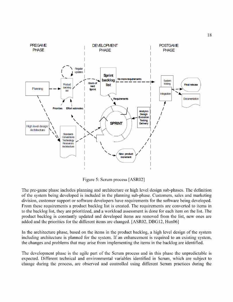
18

19
Sprints of the development phase (such variables include requirements, resources, time frame, quality, development methods and implementation technologies and tools). Scrum aims to control these variables constantly to be able to adapt flexibly to possible changes.
The software is developed in Sprints in the development phase. Sprints are iterative cycles where new increments are produced as new functionality is developed or the current system is enhanced. Multiple teams can be involved in developing an increment. Each Sprint includes requirements, analysis, design, evolution and delivery phases. One sprint is usually planned to last from one week to one month.
The post-game phase includes the closure of the release. When an agreement has been made that environmental variables, such as the requirements are completed, the post-game phase is entered. In this phase no new issues or items can be created. The system is ready for the release, and preparation tasks for the release, which include integration, system testing and documentation, are conducted.

20
4 Software testing
This chapter describes the basics of software testing and introduces the different levels of testing. Also the concepts of fault and failure are defined and the functional testing method is described. An examination into software testing is conducted in Chapter 8.
4.1 Overview of software testing
Software testing is an important part in the software development life cycle. Testing can be described as the process of testing the software under development, prior to its deployment. The objectives in software testing are to detect failures in the operation of the software and to verify that the failures have been corrected. The program to be tested is basically executed with the desired input, and the operation and the output of the program is observed and compared with the expected operation and output. If the operation of the program meets its operational criteria and the output of the program is the same with the expected output, the program can be stated to be operating correctly. If an anomaly is found regarding the required operational functionality of the program or the output of the program, the program is not working correctly and the cause for the problem must be identified. Testing is expensive and it can consume from one-third up to one-half of the cost of a typical software development project. Software testing is largely a systematic process but also partly an intuitive one. A good software testing process includes more than just executing a program few times to determine its correct operation. [Sin12]
4.1.1 Functional testing
Functional testing techniques aim to develop test cases that most probably will cause the software to fail. The technique attempts to test every possible function of the software. In functional testing, the internal structure of the software is ignored and the focus is on designing the test cases on the basis of the program's functionality. Selected inputs for the program should result in certain expected outputs. The expected outputs are compared with the observed outputs generated by the program. The software in functional testing is treated as a black box and, therefore, it is called black box testing. Functional black box testing is shown in Figure 6. [Gus02, Sin12]

21
The dots in the input domain represent a set of inputs for the software, and the dots in the output domain represent the corresponding outputs for the set of inputs. The test cases are designed based on user requirements, and it is not required to consider or to know the internal structure of the program. This black box knowledge is sufficient in order to be able to design a good variety of different test cases. Many real life activities like calling with a mobile phone or driving a car are performed with only black box knowledge.
The execution of a program is essential in functional testing and these testing techniques fall under the category of validation. The behavior of the program is observed by using both valid and invalid inputs for the program. These techniques can be used at all levels of software testing. Different software testing levels are described in detail in Chapter 4.1. These techniques also help the test designer to develop more efficient and effective test cases in finding faults from the software.
4.1.2 Fault versus failure
It is important to clarify the terms “fault”, “error” and “failure” to fully understand the concept of software testing. The terms are strictly related, but there are important differences between them. [Tha05, Wat09]
A failure is the inability of the program to perform a required function. This is manifested by a system malfunction, which shows as abnormal termination, incorrect output or as unmet space and time constraints. The cause for a failure can be, for example, a missing or incorrect piece of code, which itself is a fault. A fault can remain undetected for long periods of time until a certain event activates it. When this happens, the program enters into an unstable state called error. The error state causes the program to propagate an output which eventually causes the failure. The failure process can therefore be summarized into the following process chain:
Figure 6: Functional black box testing [SIN12]

22
Fault → Error → Failure
Testing reveals a failure and an analysis is required to identify the fault that caused the failure. The notion of fault is ambiguous and difficult to grasp. No precise criteria exist to determine the cause of an observed failure. It would be, therefore, preferable to speak about failure-causing inputs, meaning the sets of inputs that, when used, can result in a failure.
4.2 Levels of testing
During the development life cycle of a software product, software testing is performed on different levels. The testing can involve whole levels or parts of it. Depending on the selected software development method, software testing can be separated into different phases, where each phase addresses the specific needs of the different parts of the system. In software testing, whichever software development method is chosen, unit, integration and system test levels can be distinguished at least in principle. These test levels are the test phases in a traditional phased software development process such as the waterfall method. However, the three levels can also be distinguished in more modern software development methods, including the agile software development method. The levels remain useful in emphasizing the three logically different phases in the verification of a complex software system. None of the test levels are more important than the other, and as each level addresses a different type of failure, one test level cannot be substituted with another. Figure 7 shows the different levels of software testing. [Tha05, CG08]
Figure 7: Software Testing Levels (redrawn) [Tha05]
Unit Test Integration TestSystem Test
Acceptance Test
Regression Test

23
4.2.1 Unit testing
Software is developed in small units. Every unit is expected to have a defined functionality. A unit may be called a module, procedure, function or component etc. and can be developed independently and simultaneously and will have its own purpose. A. Bertolino and E. Marchetti have defined a unit as [BM04, Sin12]:
”A unit is the smallest testable piece of software, which may consist of hundreds or even just a few lines of source code, and generally represents the result of the work of one or few developers. The unit test cases' purpose is to ensure that the unit satisfies its functional specification and / or that its implemented structure matches the intended design structure.”
Interfaces, local data structures and boundary conditions could also be tested in unit testing [Tha05]. Issues may arise in unit testing, if the unit to be tested cannot be run independently. A unit may need other units to function. In this case, additional source code may have to be written. A 'driver', which calls the unit to be tested, may have to be developed. Also 'stubs', which are used by the unit to be tested, may have to be developed. [Sin12]
4.2.2 Integration testing
Integration is the process of combining the pieces, components or units of the software together to create a larger component. Integration testing aims at detecting possible faults that can occur at this stage. Even though the units are individually tested in isolation in the previous unit testing step, combining the units together may reveal new faults. When units of a program are combined together, they interact with each other, and as more units are integrated together, the more complex the created component becomes. The units interact with each other through communication interfaces. Integration testing focuses on the communication interfaces in order to verify that the units interact with each other according to the specifications defined during preliminary design. [Tha05, Bur02]
There are two integration testing approaches that have been substantially used when testing traditional systems. The first approach method in integration testing is the non-incremental approach. In this approach, all the components of the program are integrated and tested at once. This is also called “big-bang” testing. The other method is the incremental approach which includes “top-down” and “bottom-up” integration and testing strategies. In the “top-down” strategy, the components are integrated from the main program down to the subordinate ones, one component at a time, to construct the system. In the “bottom-up” strategy, the components are integrated and tested starting from the components in the lowest hierarchical level and progressively linking the components by moving up in the hierarchy.

24
Usually a mixed approach is used. The approach is usually determined by external project factors such as availability of modules and/or testers and release policy.
The “top-down” and “bottom-up” integration approaches are not usable in modern object-oriented and distributed systems, as “classical” hierarchy cannot be identified between software components. In this case, other criteria for integration testing are used, and the integration of software components is based on identified functional threads. Testing is focused on the classes used in response to a particular input or system event. This is also called thread-based testing. Another method is to test together the classes that contribute to a particular use of the system.
Another approach to integration testing is to focus on testing of units with high amount of coupling. The relationship between two or more units is represented with interfaces. The closer the relationship of the two units is, the higher is their interdependence. Coupling is the measure of the degree of interdependence between units. In this approach, integration testing is focused on interfaces of units with high amount of coupling between them. [Sin12]
4.2.3 System testing
System testing is performed after the completion of unit and integration testing. Complete software is tested along with the expected environment that it is used in. Generally functional testing techniques are used, but also a few structural testing techniques may be used. [Gus02, Sin12]
A system is defined as a combination of the software, hardware and other associated parts. Together they provide the product features and solutions. In system testing, it is ensured that each system function works as expected. Also tests for non-functional requirements like reliability, stress, load, security, performance, etc. are conducted. System testing is the only testing level where both functional and non-functional requirements of the system are tested. Also all associated manuals and documents of the software are reviewed.
A proper analysis should be done for the defects found in the system testing level. Before fixing the found defect, a proper impact analysis of the problem should be conducted. Sometimes found defects are documented and mentioned as known limitations instead of fixing them. This could be the case if correcting the fault would be time consuming or technically impossible to conduct. After the system testing phase, customer(s) is invited to test the software in the acceptance testing phase.

25
4.2.4 Acceptance testing
Acceptance testing is the extension of system testing. When the software product has passed the previous stages of testing and is ready for the customer, the product is demonstrated to the customer. After the demonstration, the customer usually wants to use and test the product to assess their satisfaction and confidence. This may range from a systematic and well-planned usage to totally random use of the product. The testing can be done by the customer or by person(s) or an organization authorized by the customer. This type of testing is essential before accepting the final product. The testing done for the purpose of accepting a product is called acceptance testing. [Sin12, Bur02]
Acceptance testing is conducted only when the software is developed for a particular customer. If software is developed for a large amount of anonymous users (for example operating systems, case tools, compilers, etc.), then acceptance testing is not feasible. In this case, potential customers are identified to test the software. This type of testing is called alpha or beta testing. Alpha testing is done by some potential customers at the developer's site under the supervision of the developers. Beta testing is done by a large amount of potential customers at their own sites without the supervision of the developers.
4.2.5 Regression testing
After the software under development has been modified, it must be retested to ensure that new faults have not been introduced. This type of retesting is called regression testing. Regression testing is not a separate level of testing, but it refers to the retesting of a unit, combination of components or a whole system after modification. [Tha05, CG08]
Regression testing is the dominant part in testing effort in the industry because today the developed software is constantly in evolution due to technical advancements and demands by market forces. Rerunning all the previously used test cases after each modification would be time consuming and expensive. Therefore, various testing techniques have been developed to reduce the costs of regression testing and to make it more efficient. For example, selective testing techniques help in selecting the minimal set of test cases by examining the modifications and only testing the modified or affected parts of the software. Other approaches prioritize the used test cases with other criteria, such as maximized fault detection power or the amount of structural coverage. The test cases judged the most important according to the selected criteria can then be prioritized and selected to be used, up to the available budget.

26
5 Continuous Integration
This chapter introduces the continuous integration method. Continuous integration methods are further examined in Chapters 6 and 7. In these chapters, a continuous integration system in a software development organization is examined and a test process is developed for the continuous integration environment.
Continuous integration is a development practice where software is grown in small increments until it meets the set requirements. The practice emphasizes on building software by splitting the work into small components and then assembling them together. Small parts of the software, when finished, are tested and integrated directly on the mainline or trunk. Figure 8 illustrates a continuous integration system. [LV10]
Figure 8: Continuous Integration system [LV10]
To be able to scale lean and agile development, it is essential to use the continuous integration method. In continuous integration, a stable system is grown gradually by working in small batches and short cycles. This enables teams to work on shared code, and it also increases visibility of the development and quality of the system. Building the software in small increments is important because large changes will break the system in large ways, and the larger the change, the more time it takes to repair the system.

27
A classic paper by Martin Fowler on continuous integration states [Fow12]:
Continuous Integration is a software development practice where members of a team integrate their work frequently, usually each person integrates at least daily - leading to multiple integrations per day. Each integration is verified by an automated build (including test) to detect integration errors as quickly as possible. Many teams find that this approach leads to significantly reduced integration problems and allows a team to develop cohesive software more rapidly.
5.1 Requirements in human behavior
Adoption of the continuous integration (CI) method requires changes in human behavior. Continuous integration is not only about tools and automation but also about developer practice, so developers need to have the discipline to integrate their changes on a regular basis or to maintain the continuous integration environment in a working condition. This requires changes to daily habits to all developers, which can be hard for many people. It takes time to be able to change daily habits and it requires coaching. [LV10, HWS10, Ras10]
Fear of breaking the build can inhibit developers from integrating code. The developers should not be shamed for breaking the build. Fear would result in developers delaying their integrations.
Large changes should be avoided in continuous integration. Large changes to a working system will destabilize the system, and the system can break in a large way. It then takes more time to get the system back to a working state. Instead, each change should be broken into small changes. Each change can be then integrated to the system easily.
In continuous integration, the frequency of continuous integration means as frequently as possible. This can be limited by: the ability to split large changes, speed of integration or speed of feedback cycle.
The ability to split large changes into smaller ones, while maintaining the old working functionality, is a skill that must be learned. The better the developers are at splitting, the more frequently they can integrate.
The speed of integration should be high. The longer it takes to integrate changes into the code repository, the less frequently the developers will integrate. Process overhead impacts the integration effort if approval and reviews are needed before developers are allowed to integrate. This overhead should be reduced. For example, code reviews can be done on already integrated code without it delaying the integration.
The speed of the feedback cycle should be high. Changes that do not break existing tests should only be integrated by the developer. In an ideal situation, the developers run all the tests before integrating. This requires that the tests run very fast. If the tests are slow, the developer will delay the integration in

28
order to “work more efficiently”. Running all the tests in a short time is hard for large systems however. Therefore, developers only run a subset of tests before checking in, and a continuous integration system runs the remaining tests. The continuous integration system acts as a safety net by giving the developer feedback about the tests he did not run. If the continuous integration (CI) system is slow, there will be many changes during one integration cycle. This increases the possibility that the build breaks. This causes the developers not to integrate in the broken build and the developers rather batch them. Finally, when the build is eventually fixed, all the developers integrate their batched changes, which leads to a high chance that the build will break again. Therefore, the continuous integration feedback cycle has to be fast. This decreases the chance that the build will break and increases the ability to check in more frequently.
Branching should be avoided during development because it breaks the purpose of continuous integration. Making changes on a separate branch means that the integration with the main branch is delayed. The current status is not visible, so the developer does not know, if everything works together. Therefore, developers integrate on the mainline or trunk. There are a few exceptions where branching can be useful however. For example, in a situation where a customer wants the latest patches but does not want to upgrade their product. Branching can be useful also when scaling up a CI system where very short-lived branches can be useful.
Branching for customization should also be avoided. This branching should be managed through a configurable design or parametrized build instead of using the Software Configuration Management (SCM) system. It can be very difficult and time consuming to merge separate branches in the trunk if the branches have been developed for a long time.
5.2 Scaling up continuous integration
To be able to scale up a continuous integration (CI) system, the basic requirement is that the build and the tests need to be fully automated. After these are automated, the scaling of a CI system enables more people producing more code and tests. First, the probability of breaking the build increases with more people checking in code. Second, an increase in size of the code leads to a slower build and therefore to a slower CI feedback loop. These can together lead to continuous integration failure. Figure 9 illustrates the dynamics of broken builds. [LV10, HWS10, Ras10]

29
There are several techniques to speed up the build in scaling up a continuous integration system. These techniques include adding hardware, parallelizing, changing tools, incremental building, incremental deployment, dependency management and test refactoring.
Adding hardware is the easiest way to speed up the build. This requires investing in more hardware such as new computers, extra memory or a faster network connection. Hardware upgrade only requires investment and minimum effort, which makes it the easiest and best choice.
Parallelizing and distributing the build is another way of speeding up the build. Build scripts, new tools or changing tools are often required to achieve this and it requires more effort compared to adding hardware. For example, the speed of a build of a large telecom product was increased by building every component on a separate computer.
Changing or upgrading tools can speed up a build significantly. Larman C. and Vodde B. state that by simply switching compilers, they accomplished a 50 percent improvement in compile time [LV01]. According to Larman C. and Vodde B. IBM Rational ClearCase is the most common, problematic and slow tool making real continuous integration impossible because it forces code ownership. Every time ClearCase has been switched by a product group to another good and free open source System Configuration Management system, multiple benefits have been achieved. First, the build has been speeded up (up to 25% - 50% improvement). Second, the company has saved significant amount of money with the elimination of licenses. Third, the developers’ lives have been improved because ClearCase is often the most hated development tool.
Figure 9: Dynamics of broken builds [LV10]

30
You can build incrementally by only compiling changed components and running tests only for those components. This can be a difficult task because of dependencies between different components, incompatible binaries or changes in interfaces. Finding all the tests related to a changed component can be difficult. Incremental builds are prone to corruption and rarely reliable. That is why it is also a good idea to keep a clean daily build.
Incremental deployment can speed up tests when the deployment is done incrementally by using only the changed components. It can take a long time to install or deploy software on large embedded products. Incremental deployment can be difficult because it may require dynamic upgrading ability which requires changes to the system. Dynamic upgrading ability is important for example in telecommunication industries where downtime is expensive.
Managing dependencies by reducing them can speed up the build and improve the structure of the product. A common reason for slow builds is unmanaged dependencies. For example, header files including many other header files or multiple link cycles to resolve cyclic link dependencies increase build times.
Test code refactoring can significantly speed up build. According to Larman C. and Vodde B. build speed has been increased as much as 60% by test code refactoring alone. Often it is the case that many developers care less about test code than production code. [LV10]
5.3 Multi-stage continuous integration system
A multi-stage continuous integration system splits the build and executes the build in different feedback cycles. A very fast CI build system runs at the lowest level of the system. The CI build system contains unit tests and some functional tests. When this CI build succeeds, a higher-level build that contains slower system-level tests is triggered. Large products have more stages in their CI systems. Figure 10 demonstrates an example of a multi-stage CI system. [LV10, HWS10, Ras10]

31
When building a multi-stage CI system, the following issues should be taken into consideration: developer build, component or feature focus, automatic or manual promotion, event or time triggers and the number of stages.
A developer build: A developer should be able to work with a subset of the system and to be able to run unit test for it. This verification of changes before checking in is required for developers practicing CI. This should be taken into account when building automated build systems.
Component or feature focus: Traditionally multi-stage continuous integration systems are structured around components. The lowest level builds a single component, the next level builds a subsystem, and the highest level builds the whole product. Teams are organized around components and each team takes care of the CI system they use. An alternative is to structure the CI system around features. In this system, all the feature related continuous integration systems are triggered when a developer checks in code. Tests are now run in parallel, but a component is compiled multiple times.
Figure 10: Scaled Continuous Integration system [LV10]

32
Automatic or manual promotion: All stages of a CI system should not listen to the main branch, as this will create disorganization. In such a case, all of the stages fail when a developer makes a mistake. An announcement is required that triggers a higher-level CI system indicating that the component can be used. This announcement is called a promotion and it is done by labeling the component. Component promotion can be done manually or automatically. In manual promotion, the component is promoted manually by developers, when certain criteria for the component have been met. In automatic promotion, a lower-level CI system promotes a component after it has passed.
Event or time triggers: All of the CI systems are triggered by either time or by an event. The low-level CI systems are always triggered by an event, for example a code check-in. The trigger for higher-level CI systems is either time or the promotion of a component. A promotion trigger is faster than a time trigger, but for slow builds, the amount of required configuration and maintenance is too high for promotion trigger to be feasible. In this case, a higher-level build could perform adequately.
The number of stages: The size and amount of legacy code in the product determine how many levels of CI systems are needed. Common CI stages are: fast component level, slow component level, product stability level, feature level and stability performance level.
The fast component level in the continuous integration system is a very fast level for receiving fast feedback. The fast component level runs unit tests, code coverage, static analysis and complexity measurements. The slow component level is a slower low-level CI system. The slow component level runs component level or integration tests. The product stability level is a very fast product level CI system for receiving fast feedback on the basic product stability. This level runs fast functional tests, for example smoke tests. The feature level is a slow, high-level CI system. The feature level executes system level tests that can last for hours. The stability performance level is a slower high-level CI system that continuously runs performance and stability tests. The duration of these tests can take days or weeks.

33
6 Evolution of the Ericsson Mobile Media Gateway development
The organization developing Ericsson Mobile Media Gateway at Ericsson Finland has evolved from the waterfall way of working to the agile way of working. This chapter explains the previous and the current M-MGw development methods, how the organization has evolved to the current state and the motivation behind the process.
6.1 M-MGw agile transformation motivation
The main motivation for M-MGw agile transformation at Ericsson Finland derived from the desire to reduce redundant work, to create more organizational value and value to the employees and customers. Though projects in the past were successful, a strong feeling existed in the organization, that it was mature enough to take the next step. A simple rule of thumb target was set, which was that the organization should only perform value adding activities. Activities that do not add value should be recognized and eliminated. No value adding activities were recognized including, for example, unnecessary task swapping, waiting, hand-offs, team internal trouble reports, unused documentation and partially done work, which has no guarantee that the customer will ever apply. [Kiv11a, Kiv11b, Arv11]
Second motivational reason to change to the agile way of working was the improvement of responsiveness. Rapid deliveries would allow customers to delay software related decisions. Software could then be produced rapidly once the customer made the necessary decisions. Another benefit from the improved of responsiveness is that software can be delivered before customers change their mind about the requirements of the software. Using this type of delivery method will eventually lead the organization to continuous deployment thinking, which has benefits on business level.
Third motivational reason for agile transformation was the ability to force quality into the software. In the past, very long periods of time were spent testing the quality of the software before the release. Now with the agile way of working, cross functional teams who are capable of both developing and testing the software use continuous integration and short feedback loops to detect faults and measure software quality. The benefits of the agile way of working can be seen in improved software quality.
Fourth reason for agile transformation was the gained benefits from people empowerment. People in the organization were granted extended permissions to organize themselves and to determine how co-operation is done and what skills need to be learned so that the people are able to carry out the needed and right operations in achieving a successful outcome. Empowering people means that everyone is

34
involved in the operation, and using this type of self-organization method, the full potential of the people in the organization is utilized.
6.2 M-MGw agile transformation process
In 2008, Ericsson Finland made the initial step towards transformation to the agile way of working. The transformation was initiated from management level by an early wake-up in the beginning of 2008 when the benefits of the agile way of working were discovered at Ericsson Finland. Years 2008-2009 followed with reading and studying the agile way of working and planning the implementation steps needed for the change. [Kiv11a, Kiv11b, Arv11]
There were two fundamental differences in the way that the whole agile transformation process was carried out compared to how projects were typically executed. The first fundamental change was the transparency of the project. Individuals from all different levels of the organization could participate and affect the outcome of the process. The second change was the difference in planning of the agile transformation process. Instead of making precise plans for the change, while still following a high level vision, the difficulties were confronted by implementing the change and observing the outcome and making necessary changes as they were required.
By October 2009, the first team started using the new agile way of working. A development task of a familiar product was chosen and people with the right competences were selected to the team. The availability to choose a suitable project and the right people made the first trial of the agile way of working simpler to understand. The first agile team encountered different difficulties especially with the development environment, as it did not suite the agile way of working well enough. However, after overcoming these challenges, the first agile team trial was a success, and the new way of working was decided to be scaled up to four teams.
Eventually the whole organization had transformed into the agile way of working by the middle of 2010. The work still continues in 2014, as methods are implemented to increase the efficiency of the agile way of working. Figure 11 illustrates the agile transformation process at Ericsson Finland.


36
Figure 13: Employee survey about the productivity at Ericsson Finland
4,9% 4,1%15,5%
12,9%25,2%
21,7%25,2%
40,7%22,4%
28,8%
13,8%
16,1%
14,1%
7,3%
1,9%
1,8%
8,9%
22,4%12,3%
0 %
10 %
20 %
30 %
40 %
50 %
60 %
70 %
80 %
90 %
100 %
M-MGw/April 2010 M-MGw/December 2010 LMF/August 2011
NA
No answer/No opinion
Much less
Less
About the same
More
Much more

37
6.3 Differences between waterfall and agile way of working
Many differences exist between the previous waterfall working method and the current agile working method. The main differences between these two methods in the Ericsson Finland organization are summarized in Table 2. [Kiv11a, Kiv11b, Arv11]
The main differences in the agile way of working compared to the waterfall method at Ericsson Finland are in the agility and flexibility of the agile method. Previously big projects were undertaken with a goal of achieving a major software release. Now the development is decoupled from big projects, and the software releases are flexible, meaning that smaller software releases are done and done more often. The previously existing barriers between system, development and test organizations are broken down, and people from different organizations now work in the same teams. This enhances communication and co-operation between people working in different phases of the software development. Individual offices no longer exist and people work in team spaces where teams share the same work space and tables. This also increases the level of co-operation and communication between team members. Specialized and narrow competences are no longer emphasized. Instead, the emphasis is on individuals being able to carry out multiple different tasks from development to testing and continuously learning new skills as the development is carried out. Individual developers and accomplishments are rewarded on team level. Individuals are encouraged to help the team accomplish its goals, rather than succeeding on an individual level. Agile and lean thinking focusing on flexibility in every level of the organization is emphasized instead of strictly following detailed processes. Top down control of managing everything hierarchically from the top level down is no longer part of the organization’s practices.
Table 2: Main differences between the Waterfall and Agile working methods (redrawn) [Kiv11a]
Waterfall model Agile Development model
Big projects Decoupled development and flexible releases
System/development/test silo organization Cross functional teams
Individual offices Team spaces
Narrow and specialized competences Broader competences and continuous learning
Individual accomplishment Team success
Following a defined and detailed processes Agile and Lean thinking
Top down control People initiative and self-organization
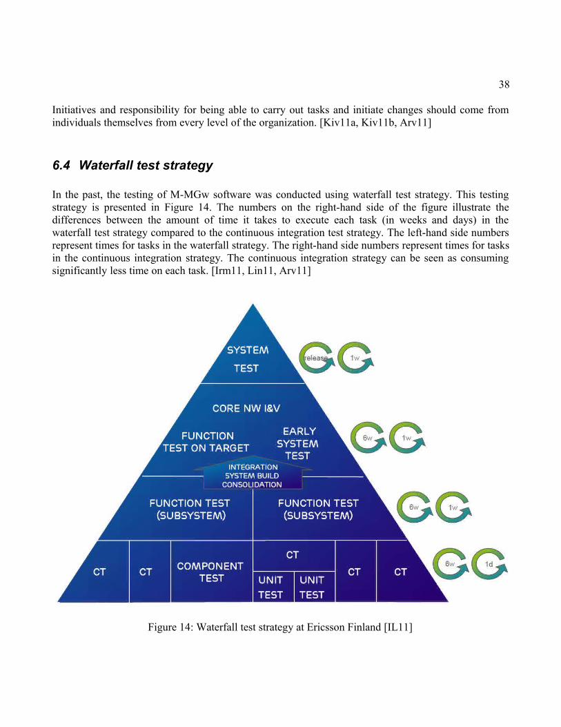
38
Initiatives and responsibility for being able to carry out tasks and initiate changes should come from individuals themselves from every level of the organization. [Kiv11a, Kiv11b, Arv11]
6.4 Waterfall test strategy
In the past, the testing of M-MGw software was conducted using waterfall test strategy. This testing strategy is presented in Figure 14. The numbers on the right-hand side of the figure illustrate the differences between the amount of time it takes to execute each task (in weeks and days) in the waterfall test strategy compared to the continuous integration test strategy. The left-hand side numbers represent times for tasks in the waterfall strategy. The right-hand side numbers represent times for tasks in the continuous integration strategy. The continuous integration strategy can be seen as consuming significantly less time on each task. [Irm11, Lin11, Arv11]
Figure 14: Waterfall test strategy at Ericsson Finland [IL11]

39
The waterfall test integration strategy presented in Figure 14 starts from low level unit testing executed by a developer. In unit testing, a developer evaluates and designs the needed tests himself to test a sub-function that he is currently working on. Depending on the function being worked on and from the developer, unit testing is not always performed. In this case, the first testing step is component testing.
Unit testing is followed by component testing. Component testing is done in component testing teams where each team specializes on a certain component. Component testing includes tests on functions themselves and on internal interfaces of functions in a load module. Load modules are described in Section 2.2.
Function test phase includes load module testing. Load modules are tested together with other load modules. The functionality of a load module's external interfaces to other load modules are tested, and also load module group tests are conducted together with control plane load modules.
Early system test and function test on target are the first phases where testing is conducted with real hardware, which in this case consist of the M-MGw. The functionality of the software is tested in the M-MGw, where possible hardware conflicts with software are tested. Traffic is also generated to the M-MGw to test the functionality of different call cases.
The final step in the testing process is the system level test, where characteristics, software upgrade and speech quality of the M-MGw with the new software is tested. The functionality of software upgrade paths from previous versions are verified before delivery. Speech quality of different call cases are also checked, so that their quality meets set standards.
6.4.1 Branching in the waterfall test strategy
In the previously used waterfall working method, each developed new feature is designed on a snapshot of the currently available version of the main software track of the M-MGw. Using this snapshot of the main software track, to develop new features on, is also called branching. The process can be seen from Figure 15. The branch does not evolve with the main software track of the M-MGw. The development and testing of a new feature can therefore take a significant amount of time. As the feature is developed on the branch, the main software track of the M-MGw could have evolved many steps compared to the main software track version used in the branch. Branching at Ericsson Finland is illustrated in Figure 15. [Irm11, Lin11, Arv11]

40
Figure 15: Branching in Waterfall test strategy [IL11]
Using branching in developing new features can lead to many problems. First, the version differences between the main track version of the M-MGw and the branched main track version of the M-MGw could be significant. This can make the integration of the new feature back to the main track difficult and time consuming. Second, each branch has a separate own test track, which leads to the same faults being found from different branches. This increases unnecessary testing, as the same tests are conducted to different branches. Third, fixes for the same faults have to be made to each of the branches and to the main track separately. This increases the amount of required work since the same faults are corrected many times to the different shipment (SH) tracks.
6.5 Continuous integration test strategy
Currently continuous integration test strategy is used at Ericsson Finland. This method does not utilize branching in the development of new M-MGw features like the previously used waterfall test strategy did. In continuous integration test strategy developers make constant integrations of new code to the main track. Automated CI system takes care of building and integrating the code to the main software track of the M-MGw and initializing the testing of the main track with the integrated code. Tests for the integrated code are conducted in a simulated environment and also on the target hardware, that is to say, on the M-MGw. Automated processes perform integration, building and testing of the new

41
software several times a day. The lead time in receiving test feedback from the process is few hours. This is a significant improvement compared to the previous waterfall test strategy where reaching target hardware tests could take several weeks or months. [Irm11, Lin11, Arv11, IL11]
In the continuous integration process, the development and testing are done in an incremental and iterative manner. The process includes developer, team, common and system levels. Each level has a certain set of tasks and the tasks are performed iteratively through a repeated cycle. The cycle of tasks is iterated until all of the tasks at the level are performed successfully or one of the tasks fails in a way that it requires iteration from a previous level of the CI process flow. Multiple teams and their developers perform this continuous integration process continuously and simultaneously. The software is developed and tested in small increments at each level. The CI process is presented in Figure 16.
Figure 16: Continuous integration strategy at Ericsson Finland [IL11]
The developer level includes tasks performed by a single developer. The developer creates a sub-function using Test-Driven Development method, where the tests for the sub-function are written before the sub-function itself. Once the developer has cycled between the development and testing
42
phases and has achieved a sub-function that meets the functionality demands, the sub-function is integrated into a team build for further testing.
The team level includes tasks performed to the team build. The team build is an internal build intended only for the team’s internal use. New functionalities implemented by team members are tested together in the team build. The team build is integrated into a simulated load module for smoke testing. If the smoke tests are performed successfully, the sub-function code developed by the team members is integrated into the main track of the M-MGw.
The common level includes test automation that essentially enables the possibility to use continuous integration method and agile way of working at Ericsson Finland. Automated CI system takes care of integrating fresh code into the main track of the M-MGw software and building of a new target build. Simulated legacy tests and smoke function tests on target hardware are performed simultaneously. The legacy tests perform thorough tests for load modules that are affected by the new software. Load modules are tested together with other load modules in an environment that simulates a real M-MGw. Smoke function tests on target hardware include tests for the new software on real M-MGw hardware. Depending on the reports of the automated CI tests, a new iteration of the CI process is done for the software to repair it, or if the tests are successful, the load modules are sent for further testing to the system level.
The system level includes tests for the load modules on the M-MGw hardware which is connected to a real network with other hardware that communicates with the M-MGw. Load, characteristics and quality of service tests are performed for the load modules in the M-MGw to determine whether they meet the performance requirements under heavy traffic with other network equipment. Also upgrade tests are performed at this level to determine whether the new software meets the performance requirements for upgrades and that all the required upgrade paths function correctly.

43
7 Fast feedback response test
The previous chapter described the past and present test strategies and processes at Ericsson Finland and how and why the transformation to the agile way of working and to the current processes was performed. The objective of the fast feedback response test, described in this chapter, is to further improve the current test methods and the agile way of working.
7.1 Fast feedback test case description
The purpose of the fast feedback response test process is to provide the developers with rapid feedback on the functionality of software in the M-MGw. The aim is to reduce the time of the feedback cycle of the code functionality tests by 80% compared to the current test processes. Therefore, the maximum amount of time for the test process to provide feedback is 15 minutes. The objective of the test process is to test that the new developed software functions properly in the node and that it does not break the legacy software in the M-MGw. The test is not intended to be a comprehensive M-MGw examination, but to check the most common indicators of faults in the functionality of the M-MGw, and to be able to perform the task automatically, without the need for human interaction, in the Ericsson continuous integration environment. The selected M-MGw fault indicator checks and call cases in the test are based on interviews made with several Ericsson M-MGw experts, covering all the main functions, most relevant interfaces (ATM, TDM, IP) and call codecs. [AAT11, Arv11].
The fast feedback test case is developed as part of this thesis. The test case is written using the Java programming language and compiled using specially designed Media Gateway Automated Test Environment (MATE) platform specific Java compiler. MATE test platform is used to run the test case. The platform is used in the system verification phase of the M-MGw testing, where regression and robustness tests are conducted on the M-MGw. The platform provides functions such as resource handling, test executor for Java test cases, graphical and command line interface for the test execution and connectivity and command line interfaces to MSC-S and M-MGw.
The purpose of the fast feedback test case is to test the main functionality of the M-MGw, that is to say, the ability to transmit traffic correctly. The test case is therefore built accordingly to be able to detect the areas where errors are expected to occur during traffic transmission process. The fast feedback test case can be divided into three parts: pre-check, traffic generation and post-check parts. In the pre-check part, error indicator counters, alarms, trace error log and the amount of dumps are stored for comparing differences in the post-check part. In the traffic generation part, traffic is generated to the M-MGw to determine the functionality of different call cases in the M-MGw. The post-check part contains all the analysis in determining whether the test case will return a pass or a fail verdict.
Differences in error indicator counters, alarms and the amount of dumps are compared between the values collected in the pre-check part and the values collected in the post-check part. Also the different, generated call types are tested to detect their functionality. If any difference between post- and pre-

44
check parts or a failed call type is found, the test case will be flagged as failed. The specific changed counter or produced error message is printed to the test logs, and MATE platform specific threshold for the counter or the message is set to “Error” or “Warn”. This enables the threshold level filtering to detect errors using the MATE platform specific web based log reader. Figure 17 shows an example of the fast feedback test case reporting on the MATE platform.
Figure 17: MATE test case reporting system
Figure 18 illustrates the fast feedback test case process and the checks included in it. The checks selected for the test case are based on expert interviews and cover the most crucial and relevant elements of the M-MGw operations [AAT11, Arv11]. The checks included in the test are:
Calls check: UTMS Traffic load generator is used to generate traffic to the M-MGw. A total of 105 different call types were selected to be generated to the M-MGw in the test case. The call types to be generated and tested were selected according to M-MGw expert interviews [AAT11]. UTMS analyzes the success of each individual call. A call is determined successful if an end-to-end connection is established successfully with the appropriate messages and if the disconnection process is also done accordingly with the appropriate messages. UTMS generates a call statistics report which is fetched by the fast feedback test case using communication interface provided by MATE. The different call types in the generated traffic are run simultaneously. One call per call type is generated to the M-MGw. Hold time for each call is one minute. In the time frame of three minutes, each call is therefore conducted three times, which should be sufficient to detect the functionality of the different call types.
PMD dump check: Post Mortem Dump is created if a program crashes in the M-MGw. Several programs run in the M-MGw providing the main service functions of the M-MGw. Information

45
about the error is saved in the Post Mortem Dump area, and then saved into a file. A check is conducted to determine whether new PMD dumps were created during the test process. [DMP12]
DSP dump check: Digital Signal Processor dump is created every time a Digital Signal Processor crashes. A DSP is a processor executing special purpose software on a device board. A typical task is processing user plane data. A check is conducted to determine whether new DSP dumps are created during the test process. [Tro12]
General MeSC counters check: General Media Stream Controller (MeSC) counters check performs different external communication interface related error counter checks. [Dat12]
Mesc counters AAL check: MeSC counters AAL check performs counter checks for Asynchronous Transfer Mode Adaptation Layer 2 (AAL2). [Dat12]
Mesc counters IP check: MEsC counters IP check performs error counter checks for IP Bearer Control Protocol which is applied to establish IP bearer connections between M-MGw nodes. [Dat12]
Mesc counters device check: MeSC device check performs error counter checks for different services provided by the M-MGw, such as echo canceling and tone sending. [Dat12]
Mesc counters GCP check: Checks the amount of sent and received Gateway Control Protocol (GCP) commands, including the number of failed commands with information about the used error codes. [MeS12]
Command handler (Ch) counters check: Checks GCP message related statistics for all of the Virtual Media Gateways (VMGws). One physical M-MGw can function as multiple Media Gateways which are called Virtual Media Gateways. [Ch12]
Some errors are printed to logs called the “List error log” (Llog) and the “Trace & Error log” (TE log).


47
Test automation tool (Tatool) is an automated software upgrade tool for the M-MGw. Tatool performs the automatic insertion of new software to the M-MGw and initiates the fast feedback test case using MATE client. Tatool is written in the Perl programming language.
Managed object shell (Moshell) is a command line shell interface for operation & maintenance of the M-MGw. Moshell is the main interface used in the operation of the M-MGw.
Media Gateway Automated Test Environment Client (MATE Client) is the graphical and command line user interface for executing test cases. MATE Client controls the MATE server.
Media Gateway Automated Test Environment Server (MATE Server) processes the fast feedback test case. The MATE server software runs on a server operating on Solaris 8/9 operating system. MATE server is controlled by MATE client.
The fast feedback test case is written using Java language. It tests the functionality of the M-MGw by performing several checks and initiating traffic to the M-MGw. The test case is executed using the MATE client. The fast feedback test case is described in more detail in Section 8.1.
The UMTS Traffic Model Simulator (UTMS) simulates network components, such as User Equipment (UE), Base Station Controllers (BSC) and Radio Network Controllers (RNC). This simulated environment is used to generate MSC-S controlled traffic to the M-MGw. UTMS Control part runs in a Solaris server and it controls the UTMS Control Client which is located in the Genesis node. UTMS also detects failing call types, generates error reports and transmits this information to the MATE server. [UTM01]
Genesis node is a Cello Packet Platform (CPP) based standalone node used for control plane and user plane traffic generation. Genesis node is essentially a scaled down version of the M-MGw. UTMS Control Client software resides in the Genesis node and controls user plane generator software in the Genesis node in generating traffic to the M-MGw. The CPP is described in Chapter 2. [Gen01]
The Mobile Switching Center Server (MSC-S) provides centralized control of the distributed switching provided by the Mobile Media Gateway (M-MGw). The MSC-S provides functions, such as call control for circuit-based services, including bearer services, supplementary services, and charging and security. The MSC-S also provides functions for user-plane resource control for circuit-based services in the M-MGw, mobility and connection management, with capabilities to support mobile multimedia control of different transport networks including TDM, ATM and IP. [MSC01]
The Mobile Media Gateway (M-MGw) provides distributed switching by connecting mobile calls locally to other mobiles and landlines [MGW08]. The M-MGw is described in more detail in Chapter 2.

48

49
the M-MGw continuous integration environment. Parts of the ideal test process are performed manually or by using an alternative process. The two test phases are designed to answer these two questions:
1) Can the test case detect obvious faults in the M-MGw?2) Can the test case perform in an automated test environment?
An obvious fault is defined as a critical fault that has a degrading effect on a main service provided by the M-MGw. Results from the two phases are analyzed to determine whether the test case can be implemented as part of the continuous integration system.
In the first phase, load modules, which cause the M-MGw to fail, will be injected into the node to determine if the test can detect any obvious faults. In the second phase, local M-MGw node development packets will be tested in an automated environment to determine if the test can perform in an automated test environment and detect known faults in the development packets.
7.3.1 Test process for faulty load module injection
In the first phase of the evaluation study, the performance of the test case in detecting obvious faults in the M-MGw is examined. Faulty load modules were produced to test the performance of the test case. A load module is a software component in the M-MGw that performs a service provided by the M-MGw. Faulty load modules were injected to the M-MGw manually and the fast feedback test case was executed after the injection. The faulty load modules replace the correctly functioning load modules in the M-MGw.
The test was conducted in two phases with two versions of a load module where different faults were introduced in them. The load module where the faults are introduced is the MeSC load module which processes incoming and outgoing traffic in the M-MGw. The load modules are designed to work with the latest software version (R6.2.2.0) of the M-MGw. Both of the injected MeSC load modules will replace the existing MeSC load module in the node. The injection will be done using MOShell software which is a command line shell for controlling Ericsson M-MGw’s. The fast feedback test case is manually initiated after a successful load module injection. Figure 20 illustrates the process of the faulty load module injection and testing.


51
conference calls because they require more than two terminations per context. Other call types should function normally. Different MeSC errors should also occur in the MeSC load module.
The second MeSC load module to be injected into the M-MGw should cause software crashes when any traffic is generated to the M-MGw. The M-MGw should not be able to transmit any traffic, and different MeSC errors should occur in the M-MGw.
Repeated test runs on both of the load modules and also with a fully functioning M-MGw are conducted. The test process is conducted ten times consecutively on both of the faulty MeSC load modules and on a functioning MeSC load module to verify the test results and to test the stability of the test case. Therefore, a total of thirty test runs will be conducted in this experiment.
This test process does not meet the automation requirements for the fast feedback test. The desired test process should be able to perform autonomously for a period of time testing multiple load modules without the need for human interaction. However, this test process is used to verify that the test case can detect faults in the M-MGw and that it is possible to execute the test process from load module injection to receiving a response within the required 15 minute time criteria. The manual load module injection method used in this test is similar to what a desired automated load module injection program, in the test process, would do automatically. The desired automatic load module injection program would execute the same commands in the MOShell and inject load modules into the M-MGw.
7.3.2 Test process for automated testing of development packets
In the second phase of the evaluation study, the feasibility of the fast feedback test case will be determined by the ability of the test case to detect faults from the local M-MGw node development packets and to evaluate the performance of the test case in an automated environment. The development packets are used in internal testing in the M-MGw development organization. Consecutive versions of the local node development packets are tested in the automated testing process. Ten Consecutive versions of the local node development packets, which include over two months of software development, will be tested in the automated testing process. The test will be repeated ten times to verify the results of the tests. Figure 21 illustrates the automated test process.


53
process with another development packet or ends the process if there are no more development packets to be tested. The program reads a file where a set of upgrade jobs and fast feedback test case initiations are defined.
This test process does not meet the requirement of the maximum duration of 15 minutes for the fast feedback test. The upgrade phase, with a duration of 30 minutes, is the bottleneck in the process. However, the duration of the test process is not a constraint in this test phase, as the purpose of this test process is to simulate an automated CI environment. The objective of this test phase is to determine the ability of the fast feedback test to function in the Ericsson environment, and the ability of the test to detect faults in the development packets.


55
Counter AAL2 is related to the last error: “Mesc counters GCP NOT OK”. Parts of the messages causing the “Mesc counters GCP NOT OK” error can be seen below: “GCP Error SubtractRsps_Errorcode_411_(Transaction refers to unknown CtxtId)_Originating from MeSC at location 12 was received 3 times (1159 OK) in board/vmgw: 000600/0 during the test case.GCP Error MoveRsps_Errorcode_434_(Max nr of Terminations in a Ctxt exceeded)_Originating from MeSC at location 353 was received 3 times (438 OK) in board/vmgw: 000900/0 during the test case.”
The messages indicate that the maximum limit of terminations per context is being constantly reached. The whole “Mesc counters GCP NOT OK” error message report can be seen in Appendix B – Error Trace of M-MGw fast feedback test.
The received GCP errors, failing conference calls, the restriction of maximum terminations per context and the requirements of the conference calls indicate to the fact that the test has detected the introduced fault in the load module. The maximum terminations per context in the load module was set to two. Successful conference calls require more than two terminations per context. This would explain the received GCP errors for exceeding the maximum terminations per contexts, as the M-MGw tries to reserve more terminations for the conference calls per context than the number of available terminations. Only the conference calls are being detected as failed in the test. This can be presumed to be caused by the restriction in the maximum terminations per context. The evidence presented here has strong indications that the test case has detected the introduced fault correctly. The test case should, in this case, provide sufficient information to a developer to be able to troubleshoot the problem.
The test case also detected errors in the (R6.2.2.0) software with the injected second load module. The load module had a fault introduced in it which prevents all traffic from being transmitted in the M-MGw, and it should cause a program crash. The test produced similar results as with the previous load module but with the difference that 100 % of the generated calls were detected as failed and a PMD dump creation was detected. A PMD dump is created and saved in to a file if a program in the M-MGw crashes. The dump should provide sufficient information about the crashed program and reasons for the crash. A developer should be able to troubleshoot the root of the problem by using an appropriate parser to extract information from the PMD dump file.
8.2 Test results and analysis of automated development packet testing
In this test phase, the fast feedback test case performed as designed considering the ability for the test process to perform in an automated environment, but it did not detect any faults from the development packets used in the testing. Test runs on all of the ten different development packets returned a pass verdict on all of the ten test runs. The logs gathered by the fast feedback test case were examined to detect any indication of detected but ignored faults by the test case. However, no indications of faults in the logs by manual inspection were found. Figure 23 shows parts of the MATE test session view for the automated development packet tests.


57
Fail verdicts were returned on both of the load modules on all of the test runs. The test case correctly returned error or warning messages from the failed checks. The test runs from the first load module, which concerned failing conference calls, reported the failed calls and produced error reports that could be linked to the fault. The second tested load module designed to prevent traffic transmission and to cause a software crash in the M-MGw was reported as failure of all calls by the system and produced error reports and a PMD dump. These were detected and could be linked to the introduced fault. The repeated test runs on both of the faulty load modules produced the same results on each test run. The repeated test runs on the functioning M-MGw software produced repeated pass verdicts on each test run.
The detail level of the feedback from the load module tests should be sufficient for troubleshooting. Considering the target environment of the test case where the test should be conducted several times per hour, the amount of code integrations to the main software track of the M-MGw should consist only of a few code integrations. Therefore, a developer should be able to trace the root cause of the problem by examining his latest code integration and the feedback provided by the test case.
The fast feedback test failed to find any of the known faults in the development packets. This does not conclude that the test case itself would not perform on a satisfying level, but it indicates that the testing process already performed on these packets is able to detect major faults in the M-MGw, and that the quality of the software development and testing is on a sufficient level. The fast feedback test case is designed to be executed before this test automation process, where severity of faults introduced to the M-MGw is on a scale where it is possible for the test to detect them. The performance of the test case, considering the ability of the test case process to perform in the automated test environment, was satisfactory. No error situations were encountered concerning the test process itself.
According to the test results analysis, assumptions can be made that the test case is able to perform in the current form in the target environment. No definitive answer whether the test case can perform satisfactory in the Ericsson continuous integration environment can be concluded with the tests conducted here. The conducted tests and the received results should be treated as preliminary test results. They give positive indications of the performance level of the test process. More thorough testing is required to be able to give a definitive judgement of the performance level of the test process. This requires many more faulty software packets to be tested with the test case. Due to the amount of time that would be consumed by manual packet testing, this would require the test to be analyzed in an automated test environment with a constant flow of new software packets to be continuously processed. This type of environment would be the target Ericsson CI environment itself.

58
9 Conclusions
The main purpose of this thesis was to develop a method for improving the agile software development methods. The purpose was to improve continuous integration, which is part of the agile software development methods, by developing an additional fast feedback test process. The objective of the test process is to offer additional value by providing software developers with rapid feedback on software functionality. This should then enable a more efficient detection and troubleshooting of software faults.
The study, conducted on the basis of the case example at Ericsson Finland, comparing the efficiency of the agile way of working with the waterfall way of working, indicates that the agile way of working is more efficient. The results from examining the past and present software development methods at Ericsson Finland support the fact that transforming to the agile way of working has increased the efficiency of software development at Ericsson Finland. The employee survey and the decreased amount of redundant work support this fact. The transformation to the agile way of working study was conducted as a background study to support the main objective of this thesis. Therefore, due to the limited scope of this study, the conclusion can be postulated as follows: there are strong indications that the agile way of working is more efficient than the waterfall way of working at Ericsson Finland. A definitive answer to the matter would require more research.
The fast feedback test case was developed by examining the continuous integration environment of the Ericsson Mobile Media Gateway (M-MGw) development and by conducting expert interviews. The requirements for the test case were that the maximum duration for the test process to respond does not exceed 15 minutes and that the test case should be able to detect major faults in the M-MGw. Major faults were defined as failures to provide the main service of the M-MGw, that is, the ability to transmit traffic. The test case should also be able to give sufficient information about the nature of the detected faults.
In the first evaluation study of the fast feedback test case, the ability of the test case to detect obvious faults was analyzed. The tests conducted on faulty software were successful and the results of the study indicate that the developed fast feedback test case is capable of detecting faults in the M-MGw. The test case detected the introduced faults from the software, and the amount of information provided by the test case in the tests was sufficient for a developer to be able to troubleshoot the introduced faults.
In the second evaluation study, the performance of the test case in an automated test environment with software that has passed the Ericsson continuous integration (CI) machinery and has only minor faults was examined. The experiment indicated that the fast feedback test case was unable to detect minor faults in an automated test environment using development packets. The test process itself was, however, able to perform satisfactory in the automated test environment. This study shows that the performance of the current continuous integration test machinery is satisfactory. The test machinery is capable of detecting major faults in the M-MGw software, although the response time for the feedback is considerably high.

59
These studies suggest that the test case created for this research could be able to perform in the continuous integration environment where it was designed for. However, more performance studies on the test case are required to be able to definitively evaluate its performance in its current form with the incorporated checks. These test results should be treated as preliminary performance studies of the test case. Reliable evaluation of the performance of the test case would require evaluation of tests on a much higher amount of different faulty software packets. This was not possible to do, with the tests presented in this thesis. This would require an automated test environment and a test process with constant flow of faulty software packets. This type of environment would be the target continuous integration environment. Due to time and scope limitations of this study, this type of testing was not possible to conduct.
Considering the target environment where the fast feedback test case would execute the initial tests for the integrated code, assumptions can be made that the test would provide additional value to the continuous integration environment. Initial phase of testing, in this case, is defined as the common level phase in the Ericsson CI environment immediately after the code integration. The faults in the software in the initial phase of testing are more likely to be severe, so that the fast feedback test case would be able to detect them. Therefore, it would be feasible to implement the test process to the continuous integration system. Worth noticing is that in the current form of the test process, the implementation and maintenance of the test would be expensive, as it also requires an MSC-S in addition to the M-MGw.
On the basis of these results, it can be assumed that the fast feedback response test would increase the efficiency of fault finding and troubleshooting. The results indicate that the test is capable of detecting faults and providing detailed feedback of the faults in a short time period. Considering that the test would be conducted continuously, where it provides feedback in short repeated cycles, the amount of changes in the code in that time period would be minimal. This would increase the efficiency of troubleshooting faults. The troubleshooting of detected faults could be conducted by using an alternative method, by examining only the recent changes in the code. This method is presumed to be more effective than the traditional troubleshooting methods where investigation to the problem itself is conducted.
This thesis demonstrates that it is possible to develop a fast feedback test process for verification of software functionality based on tools used in function verification level of software testing. By conducting the initial testing of software on the target level and using system verification tools to detect faults, the time of receiving feedback on software functionality can be drastically decreased. In the case of the M-MGw testing, by generating and testing different call types simultaneously, the time efficiency of the test process in providing feedback can be further increased.
The methods introduced in this thesis in enabling fast feedback response could also be applied to the agile development of other software products. A definitive answer whether the methods could be applied to the development of any other software product cannot be concluded. A further examination needs to be conducted in order to specify what tools and methods are available in the way that was

60
demonstrated in this study. This study shows that it is recommended to examine the system verification tools and methods in enabling fast feedback response in agile software development projects.
A conclusive answer, to all of the objectives presented in this thesis, cannot be given, due to the ambitious goals, the scope and the time frame of this thesis. However, there are positive indications from the research, which point out to the following facts:
1) The agile way of working is more efficient in the Ericsson Mobile Media Gateway organization than the waterfall way of working.
2) Fast feedback response can be enabled in the M-MGw development by creating a target hardware test process to initial software testing.
3) The developed fast feedback test process is capable of finding faults. 4) The fast feedback test process would be feasible to be implemented into the Media Gateway test
environment.5) The test process increases the efficiency of fault finding and troubleshooting.6) The findings in this research can be applied to the agile development of other software products.
More research on these subjects is required to be able to conclusively verify these claims. Section 9.1 describes how to further research these objectives.
9.1 Future research
To determine the efficiency of the agile way of working in the Ericsson Media Gateway organization, more research should be conducted on the subject. For example a survey from the M-MGw developers could reveal more information about the efficiency of the agile methods. Another way of studying this is to analyze data from the time spent on troubleshooting detected faults in the M-MGw in the current agile methods. The time spent could be then compared with the time spent on troubleshooting in the previous waterfall methods.
To be able to conclusively verify the feasibility and capability of the fast feedback test to perform in the M-MGw development environment, the test process should be integrated into the continuous integration environment. Thorough studies should then be conducted by collecting data and analyzing what faults the test has detected and what faults it has missed. Also a survey should be conducted to determine, if the fast feedback response adds value to the troubleshooting efficiency of detected M-MGw faults. This survey should be conducted with the M-MGw developers.
More research is also required to be able to integrate the fast feedback test case to the current continuous integration system. Additions to the continuous integration system are required. For example the upgrade time for official insertion of new software to the M-MGw is too long to be used with the fast feedback test. A method for fast software injection to the M-MGw is known, but a new

61
tool that utilizes the fast software injection method properly would have to be developed. The tool should be able to automatically fetch and inject the software to the M-MGw.
Parts of the continuous integration system should be modified to be able to implement the fast feedback test. For example, the CI system would have to be modified for a more frequent package creation and delivery to provide fast delivery of the integrated code to the fast feedback test. The current rate is too slow for the fast feedback test to operate efficiently.
The expenses of implementing the fast feedback test process should also be addressed. The expenses could be reduced by simulating parts of the hardware required in the test process. For example, the MSC-S could be replaced with a simulated version. This would significantly reduce the costs in implementing the fast feedback test process.

62
References
[AAT11] M. Ahola, T. Arvonen, and, R. Troberg, Fast Feedback meeting at Ericsson, Kirkkonummi, 20th September 2011.
[Agi01] The Agile Manifesto, The Agile Alliance Home Page, http://agilealliance.org/the-alliance/the-agile-manifesto/, 2001. Referenced July 2013.
[Agi01b] The Twelve Principles of Agile Software, The Agile Alliance Home Page, http://agilealliance.org/the-alliance/the-agile-manifesto/the-twelve-principles-of-agile-software/, 2001. Referenced July 2013.
[Arv11] T. Arvonen, Program Manager, Expert interview about Agile transformation and Continuous Integration at Ericsson, Kirkkonummi, 19th December 2011.
[ASR02] P. Abrahamsson, O. Salo, J. Ronkainen, and J. Warsta, Agile software development methods: Review and analysis, VTT, VTT Publications 478, Espoo, 2002.
[BM04] A. Bertolino and E. Marchetti, A Brief Essay on Software Testing, Technical Report: 2004-TR-36, 2004.
[Bur02] I. Burnstein, Practical Software Testing: a process-oriented approach, Springer-Verlag New York, New York, 2003.
[CG08] L. Crispin, J. Gregory, Agile Testing: A Practical Guide for Testers and Agile Teams, Addison-Wesley, Boston, 2008.
[CH01] A. Cockburn and J. Highsmith, “Agile Software Development: The People Factor”, IEEE Computer, vol. 34, no. 11, November 2001, pp. 131–133.
[Ch12] Ch Counters Command manual, Ericsson Customer Product Information document. Referenced January 25th 2012.
[Dat12] Data Collection Guideline, Ericsson Customer Product Information document. Referenced January 25th 2012 .

63
[DBG12] P. Deemer, G. Benefield, C. Larman, B. Vodde, The Scrum Primer: A Lightweight Guide to the Theory and Practice of Scrum, www.scrumprimer.org, http://scrumprimer.org/scrumprimer20_small.pdf, 2002. Referenced July 2013.
[Dia08] Ericsson AB, LMF R&D Dialog results 2008, Employee feedback poll, 25 th September 2008.
[Dia09] Ericsson AB, LMF R&D Dialog results 2009, Employee feedback poll, 28 th October 2009.
[Dia10] Ericsson AB, LMF R&D Dialog results 2010, Employee feedback poll, 3 rd October 2010.
[Dia11] Ericsson AB, LMF R&D Dialog results 2011, Employee feedback poll, 23rd Novemeber 2011.
[DMP12] Dump Manual Page, Ericsson Customer Product Information document. Referenced January 25th 2012.
[Doo11] J. Dooley, Software Development and Professional Practice, Apress, New York, 2011.
[Eri01] Ericsson Technical Product Description, M-MGw R6, December 2010.
[Eri07] Ericsson Product Description, Ericsson Media Gateway for Mobile Networks R4, 2007.
[FHP00] M. Fyrö, K. Heikkinen, L. Petersen, P. Wiss, Ericsson Review no. 4, 2000.
[Fow12] M. Fowler, ”Continuous Integration”, The official Agile Manifesto website, http://martinfowler.com/articles/continuousIntegration.html. Referenced January 2012.
[Gen01] Generic Userplane Verification System, Ericsson System Architecture Description, Genesis HW SW AI, July 2011.
[GPP01] 3GPP Technical Specification 23.002 V8.2.0. Network Architecture (Release 8). 3rd Generation Partnership Project, December 2007.
[GPP02] 3GPP Technical Specification 23.205 V8.1.0. Bearer Independent Circuit-Switched Core Network (Release 8). 3rd Generation Partnership Project, December 2007.
[Gus02] D. Gustafson, Schaum's Outline of Theory and Problems of Software Engineering, McGraw-Hill, 2002.

64
[HD08] O. Hazzan and Y. Dubinsky, Agile Software Engineering, Springer, United Kingdom, 2008.
[Hun06] J. Hunt, Agile Software Construction, Springer, London, 2006.
[HWS10] B. Holtsnider, T. Wheeler, G. Stragand, and J. Gee, Agile Development & Business Goals: The Six Week Solution, Elsevier, Burlington, 2010.
[IL11] J. Irmola, K. Lindroos, “Experiences from Continuous Integration in Mobile Media Gateway”, Presentation, Ericsson Agile Conference 2011, Kirkkonummi, 20th September 2011.
[Irm11] J. Irmola, Section Manager, Expert interview about Continuous Integration at Ericsson, Kirkkonummi, 25th November 2011.
[Jac01] I. Jacobson, A Resounding ‘Yes’ to Agile Processes – But Also More, Cutter IT Journal, vol. 15, no. 1., pp. 18-24, January 2002.
[Kiv11a] H. Kivioja, “M-MGw Agile Transformation: Experiences and Learnings”, Presentation, Ericsson Agile Conference 2011, Kirkkonummi, 20th September 2011.
[Kiv11b] H. Kivioja, Head Agile Coach, Expert interview about Agile practices at Ericsson, Kirkkonummi, 28th October 2011.
[KLM02] L. Kling, Å. Lindholm, L. Marklund, and G. Nilsson, Ericsson Review no. 2, 2002.
[Kuu08] T. Kuusimurto, Open Source Code Business Models for Mobile Media Gateway Node Manager, MSc thesis, Helsinki University of Technology, Kirkkonummi, November 2008.
[Lin11] K Lindroos, Section Manager, Expert interview about Continuous Integration at Ericsson, Kirkkonummi, 15th December 2011.
[LV10] C. Larman and B. Vodde, Practices for Scaling Lean & Agile Development: Large, Multisite, and Offshore Product Development with Large-Scale Scrum, Addison-Wesley, Boston, January 2010.
[MeS12] MeSC Counters GCP manual, Ericsson Customer Product Information document. Referenced January 25th 2012.

65
[MGW08] Media Gateway for mobile networks, Ericsson product description, 2008.
[MSC01] Mobile Switching Center MSC, Ericsson Product Portfolio, http://www.ericsson.com/ourportfolio/products/mobile-switching-center-msc?nav=fgb_101_189. Referenced 17th January 2012.
[Pre01] R. Pressman, Software Engineering: A practitioner’s Approach, 6th edition, McGraw-Hill Education, New York, 2005.
[Ras10] J. Rasmusson, The Agile Samurai: How Agile Masters Deliver Great Software, The Pragmatic Programmers, United States of America, September 2010.
[Sch11] S. Schach, Object-oriented and Classical Software Engineering, 8th Edition, McGraw-Hill, New York, 2011.
[Sin12] Y. Singh, Software Testing, Cambridge University Press, New York, 2012.
[Som11] I. Sommerville, Software Engineering, 9th Edition, Addison-Wesley, 2011, Boston.
[Tha05] R. Thayer, M. Christensen, Software Engineering Volume 1: The Development process, John Wiley & Sons Inc., New Jersey, 2005.
[Tro12] M-MGw Troubleshooting Guide, Ericsson Customer Product Information document. Referenced January 25th 2012.
[UTM01] UTMS Design Description, Ericsson System Architecture Description. Referenced January 17th 2012.
[Wat09] J. Watkins, Agile Testing: How to Succeed in an Extreme Testing Environment, Cambridge University Press, Cambridge, 2009.

66
Appendix A – The Twelve Principles of Agile Software
The Agile Alliance has defined 12 principles for achieving agility [Agi01b]:
Our highest priority is to satisfy the customer through early and continuous delivery of valuable software.
Welcome changing requirements, even late in development. Agile processes harness change for the customer's competitive advantage.
Deliver working software frequently, from a couple of weeks to a couple of months, with a preference to the shorter timescale.
Business people and developers must work together daily throughout the project.
Build projects around motivated individuals. Give them the environment and support they need, and trust them to get the job done.
The most efficient and effective method of conveying information to and within a development team is face-to-face conversation.
Working software is the primary measure of progress.
Agile processes promote sustainable development. The sponsors, developers, and users should be able to maintain a constant pace indefinitely.
Continuous attention to technical excellence and good design enhances agility.
Simplicity--the art of maximizing the amount of work not done--is essential.
The best architectures, requirements, and designs emerge from self-organizing teams.
At regular intervals, the team reflects on how to become more effective, then tunes and adjusts its behavior accordingly.

67
Appendix B – Error trace of M-MGw Fast Feedback Test
GCP Error SubtractRsps_Errorcode_411_(Transaction refers to unknown CtxtId)_Originating from MeSC at
location 12 was received 3 times (1159 OK) in board/vmgw: 000900/0 during the test case.
GCP Error SubtractRsps_Errorcode_411_(Transaction refers to unknown CtxtId)_Originating from MeSC at
location 12 was received 3 times (1159 OK) in board/vmgw: 000600/0 during the test case.
GCP Error MoveRsps_Errorcode_434_(Max nr of Terminations in a Ctxt exceeded)_Originating from MeSC at
location 353 was received 3 times (438 OK) in board/vmgw: 000900/0 during the test case.
GCP Error MoveRsps_Errorcode_434_(Max nr of Terminations in a Ctxt exceeded)_Originating from MeSC at
location 353 was received 3 times (438 OK) in board/vmgw: 000600/0 during the test case.
GCP Error AddRsps_Errorcode_434_(Max nr of Terminations in a Ctxt exceeded)_Originating from MeSC at
location 353 was received 22 times (542 OK) in board/vmgw: 000900/0 during the test case.
GCP Error AddRsps_Errorcode_434_(Max nr of Terminations in a Ctxt exceeded)_Originating from MeSC at
location 353 was received 22 times (542 OK) in board/vmgw: 000600/0 during the test case.