Embed Size (px)
Citation preview
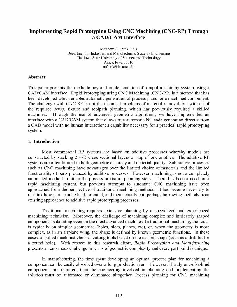
Implementing Rapid Prototyping Using CNC Machining (CNC-RP) Through a CAD/CAM Interface
Matthew C. Frank, PhD
Department of Industrial and Manufacturing Systems Engineering The Iowa State University of Science and Technology
Ames, Iowa 50010 [email protected]
Abstract: This paper presents the methodology and implementation of a rapid machining system using a CAD/CAM interface. Rapid Prototyping using CNC Machining (CNC-RP) is a method that has been developed which enables automatic generation of process plans for a machined component. The challenge with CNC-RP is not the technical problems of material removal, but with all of the required setup, fixture and toolpath planning, which has previously required a skilled machinist. Through the use of advanced geometric algorithms, we have implemented an interface with a CAD/CAM system that allows true automatic NC code generation directly from a CAD model with no human interaction; a capability necessary for a practical rapid prototyping system. 1. Introduction
Most commercial RP systems are based on additive processes whereby models are constructed by stacking 21/2-D cross sectional layers on top of one another. The additive RP systems are often limited in both geometric accuracy and material quality. Subtractive processes such as CNC machining have advantages over the limited choice of materials and the limited functionality of parts produced by additive processes. However, machining is not a completely automated method in either the process or fixture planning steps. There has been a need for a rapid machining system, but previous attempts to automate CNC machining have been approached from the perspective of traditional machining methods. It has become necessary to re-think how parts can be held, oriented, and then actually cut; perhaps borrowing methods from existing approaches to additive rapid prototyping processes.
Traditional machining requires extensive planning by a specialized and experienced machining technician. Moreover, the challenge of machining complex and intricately shaped components is daunting even on the most advanced machines. In traditional machining, the focus is typically on simpler geometries (holes, slots, planes, etc), or, when the geometry is more complex, as in an airplane wing, the shape is defined by known geometric functions. In these cases, a skilled machinist chooses cutting tools based on the desired shape (such as a drill bit for a round hole). With respect to this research effort, Rapid Prototyping and Manufacturing presents an enormous challenge in terms of geometric complexity and every part build is unique.
In manufacturing, the time spent developing an optimal process plan for machining a
component can be easily absorbed over a long production run. However, if truly one-of-a-kind components are required, then the engineering involved in planning and implementing the solution must be automated or eliminated altogether. Process planning for CNC machining
112
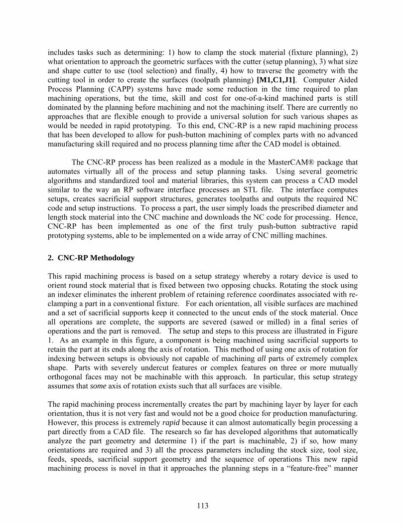
includes tasks such as determining: 1) how to clamp the stock material (fixture planning), 2) what orientation to approach the geometric surfaces with the cutter (setup planning), 3) what size and shape cutter to use (tool selection) and finally, 4) how to traverse the geometry with the cutting tool in order to create the surfaces (toolpath planning) [M1,C1,J1]. Computer Aided Process Planning (CAPP) systems have made some reduction in the time required to plan machining operations, but the time, skill and cost for one-of-a-kind machined parts is still dominated by the planning before machining and not the machining itself. There are currently no approaches that are flexible enough to provide a universal solution for such various shapes as would be needed in rapid prototyping. To this end, CNC-RP is a new rapid machining process that has been developed to allow for push-button machining of complex parts with no advanced manufacturing skill required and no process planning time after the CAD model is obtained.
The CNC-RP process has been realized as a module in the MasterCAM® package that
automates virtually all of the process and setup planning tasks. Using several geometric algorithms and standardized tool and material libraries, this system can process a CAD model similar to the way an RP software interface processes an STL file. The interface computes setups, creates sacrificial support structures, generates toolpaths and outputs the required NC code and setup instructions. To process a part, the user simply loads the prescribed diameter and length stock material into the CNC machine and downloads the NC code for processing. Hence, CNC-RP has been implemented as one of the first truly push-button subtractive rapid prototyping systems, able to be implemented on a wide array of CNC milling machines.
2. CNC-RP Methodology
This rapid machining process is based on a setup strategy whereby a rotary device is used to orient round stock material that is fixed between two opposing chucks. Rotating the stock using an indexer eliminates the inherent problem of retaining reference coordinates associated with re-clamping a part in a conventional fixture. For each orientation, all visible surfaces are machined and a set of sacrificial supports keep it connected to the uncut ends of the stock material. Once all operations are complete, the supports are severed (sawed or milled) in a final series of operations and the part is removed. The setup and steps to this process are illustrated in Figure 1. As an example in this figure, a component is being machined using sacrificial supports to retain the part at its ends along the axis of rotation. This method of using one axis of rotation for indexing between setups is obviously not capable of machining all parts of extremely complex shape. Parts with severely undercut features or complex features on three or more mutually orthogonal faces may not be machinable with this approach. In particular, this setup strategy assumes that some axis of rotation exists such that all surfaces are visible. The rapid machining process incrementally creates the part by machining layer by layer for each orientation, thus it is not very fast and would not be a good choice for production manufacturing. However, this process is extremely rapid because it can almost automatically begin processing a part directly from a CAD file. The research so far has developed algorithms that automatically analyze the part geometry and determine 1) if the part is machinable, 2) if so, how many orientations are required and 3) all the process parameters including the stock size, tool size, feeds, speeds, sacrificial support geometry and the sequence of operations This new rapid machining process is novel in that it approaches the planning steps in a “feature-free” manner
113
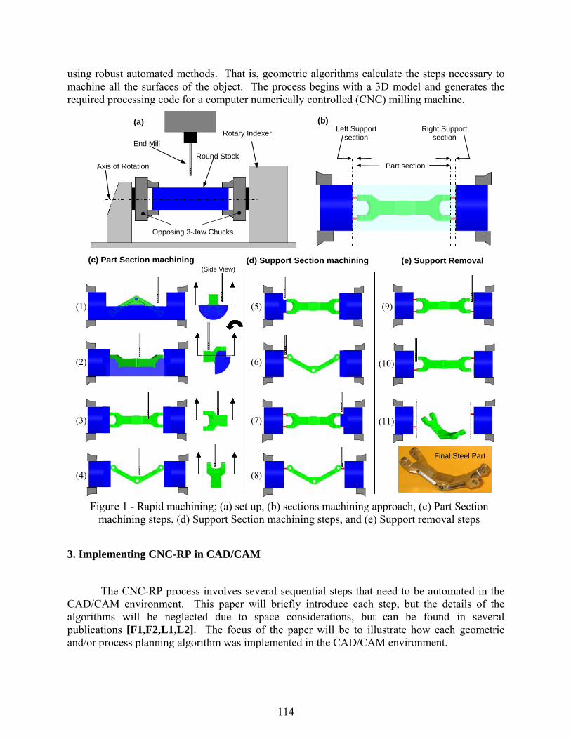
using robust automated methods. That is, geometric algorithms calculate the steps necessary to machine all the surfaces of the object. The process begins with a 3D model and generates the required processing code for a computer numerically controlled (CNC) milling machine.
3. Implementing CNC-RP in CAD/CAM
The CNC-RP process involves several sequential steps that need to be automated in the CAD/CAM environment. This paper will briefly introduce each step, but the details of the algorithms will be neglected due to space considerations, but can be found in several publications [F1,F2,L1,L2]. The focus of the paper will be to illustrate how each geometric and/or process planning algorithm was implemented in the CAD/CAM environment.
(Side View) (Side View)
(1)
(2)
(3)
(4)
(5)
(6)
(7)
(8)
(9)
(10)
(11)
(c) Part Section machining (d) Support Section machining (e) Support Removal
Figure 1 - Rapid machining; (a) set up, (b) sections machining approach, (c) Part Section machining steps, (d) Support Section machining steps, and (e) Support removal steps
Axis of Rotation
Opposing 3-Jaw Chucks
Round Stock
End Mill
(a) Rotary Indexer
(b)
Part section
Left Support section
Right Support section
Final Steel Part
114
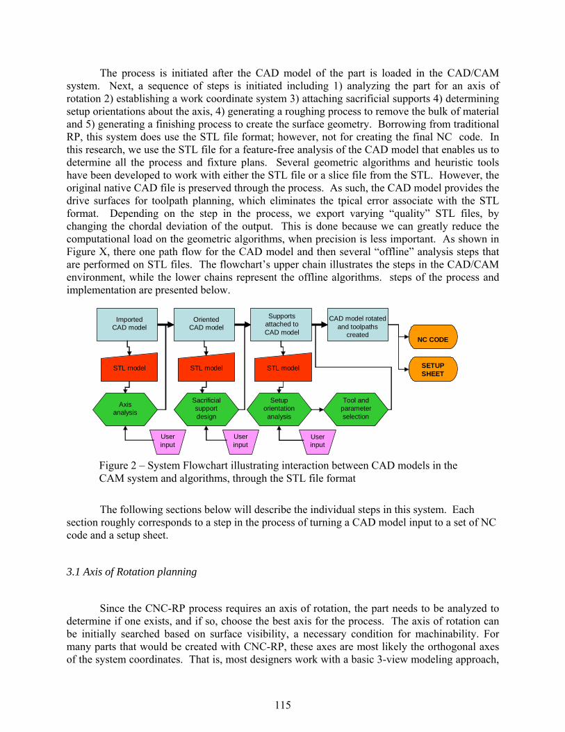
The process is initiated after the CAD model of the part is loaded in the CAD/CAM system. Next, a sequence of steps is initiated including 1) analyzing the part for an axis of rotation 2) establishing a work coordinate system 3) attaching sacrificial supports 4) determining setup orientations about the axis, 4) generating a roughing process to remove the bulk of material and 5) generating a finishing process to create the surface geometry. Borrowing from traditional RP, this system does use the STL file format; however, not for creating the final NC code. In this research, we use the STL file for a feature-free analysis of the CAD model that enables us to determine all the process and fixture plans. Several geometric algorithms and heuristic tools have been developed to work with either the STL file or a slice file from the STL. However, the original native CAD file is preserved through the process. As such, the CAD model provides the drive surfaces for toolpath planning, which eliminates the tpical error associate with the STL format. Depending on the step in the process, we export varying “quality” STL files, by changing the chordal deviation of the output. This is done because we can greatly reduce the computational load on the geometric algorithms, when precision is less important. As shown in Figure X, there one path flow for the CAD model and then several “offline” analysis steps that are performed on STL files. The flowchart’s upper chain illustrates the steps in the CAD/CAM environment, while the lower chains represent the offline algorithms. steps of the process and implementation are presented below.
The following sections below will describe the individual steps in this system. Each section roughly corresponds to a step in the process of turning a CAD model input to a set of NC code and a setup sheet.
3.1 Axis of Rotation planning
Since the CNC-RP process requires an axis of rotation, the part needs to be analyzed to determine if one exists, and if so, choose the best axis for the process. The axis of rotation can be initially searched based on surface visibility, a necessary condition for machinability. For many parts that would be created with CNC-RP, these axes are most likely the orthogonal axes of the system coordinates. That is, most designers work with a basic 3-view modeling approach,
Imported CAD model
STL model
Axis analysis
Oriented CAD model
STL model
Sacrificial support design
Supports attached to CAD model
STL model
Setup orientation analysis
CAD model rotated and toolpaths
created
User input
User input
User input
Tool and parameter selection
NC CODE
SETUP SHEET
Figure 2 – System Flowchart illustrating interaction between CAD models in the CAM system and algorithms, through the STL file format
115
adding features to the views of the orthographic projections of the part (top-front-side sketching in most CAD systems). Similarly, one could argue that most parts intended for manufacturing have been designed for as few setups as possible. So, the first step in the analysis is to simply check the x-, y- and z-axes of the part and determine their visibility. In addition, the diameter of the part along each of these axes is found, since smaller diameter materials reduce cost and tooling requirements.
Since tool access is restricted to directions orthogonal to the rotation axis, 2-D visibility maps for a set of cross sections of the surface of the model are used for visibility mapping. This procedure approximates visibility to the entire surface of the model. For example, consider the part illustrated in Figure 3. Cross sectional slices of the geometry from an STL model provide polygonal chains that are used for 2-D visibility mapping. A simultaneous visibility solution for all cross sections of the model will approximate visibility to the entire surface. For this simple model and the slice shown in Figure 3a, the chain of edges in the polygon are visible from many different orientations. If the orientations in Figure 3b illustrated by the block arrows are chosen four rotations could be used to machine the part. This implies that four orientations (index rotations) are used and all visible material from each view is removed. If the two orientations noted by the lightning arrows are used, then only two rotations are needed. In this case, two rotations is the fewest number required.
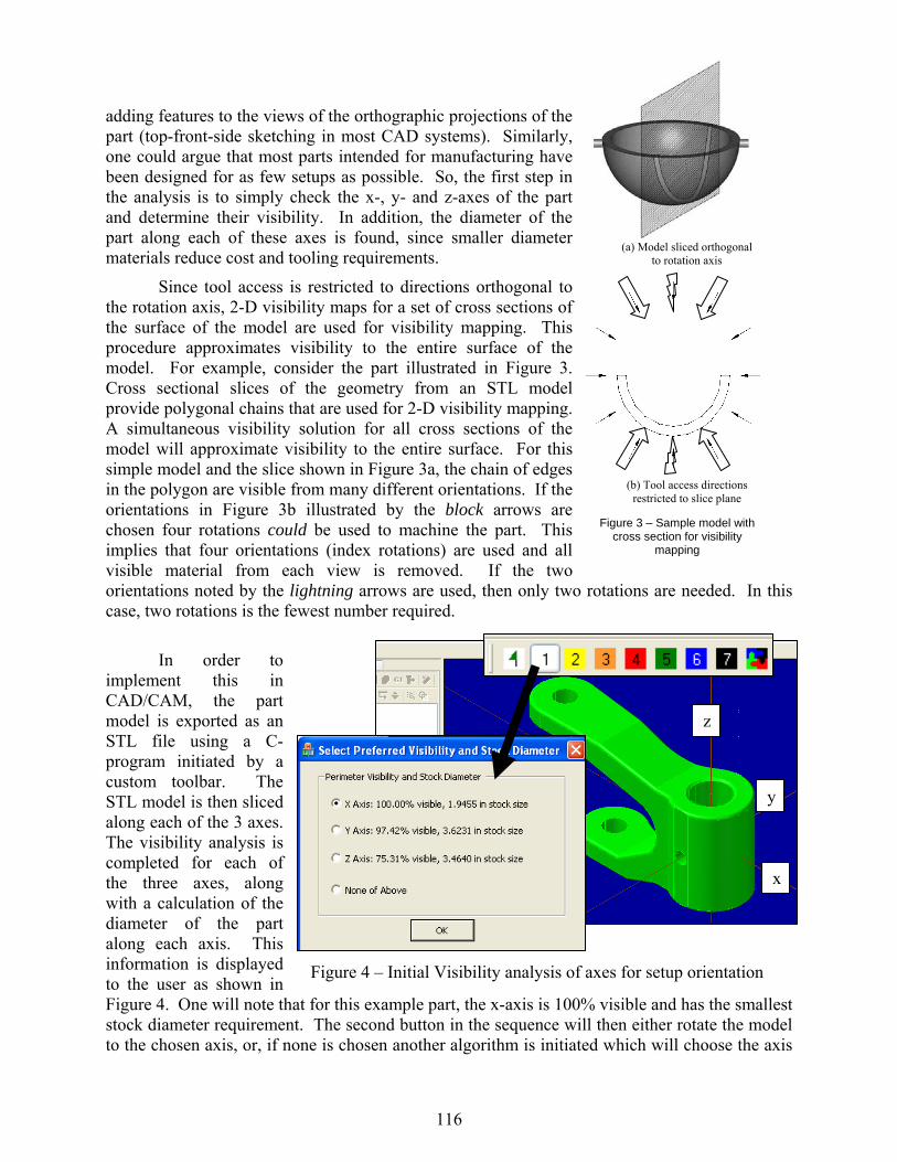
In order to implement this in CAD/CAM, the part model is exported as an STL file using a C-program initiated by a custom toolbar. The STL model is then sliced along each of the 3 axes. The visibility analysis is completed for each of the three axes, along with a calculation of the diameter of the part along each axis. This information is displayed to the user as shown in Figure 4. One will note that for this example part, the x-axis is 100% visible and has the smallest stock diameter requirement. The second button in the sequence will then either rotate the model to the chosen axis, or, if none is chosen another algorithm is initiated which will choose the axis
(b) Tool access directions restricted to slice plane
Figure 3 – Sample model with cross section for visibility
mapping
(a) Model sliced orthogonal to rotation axis
x
y
z
Figure 4 – Initial Visibility analysis of axes for setup orientation
116
for the user. This is a much more advanced option, which uses 3D visibility mapping from the STL file and calculates all feasible axes of rotation. The axis program chooses the best axis, once again based on the smallest stock diameter. The visibility program has been recently published, [L1] and the axis of rotation publication is forthcoming.
3.2 Establishing a coordinate system
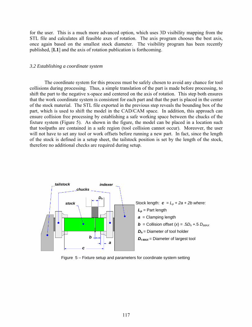
The coordinate system for this process must be safely chosen to avoid any chance for tool collisions during processing. Thus, a simple translation of the part is made before processing, to shift the part to the negative x-space and centered on the axis of rotation. This step both ensures that the work coordinate system is consistent for each part and that the part is placed in the center of the stock material. The STL file exported in the previous step reveals the bounding box of the part, which is used to shift the model in the CAD/CAM space. In addition, this approach can ensure collision free processing by establishing a safe working space between the chucks of the fixture system (Figure 5). As shown in the figure, the model can be placed in a location such that toolpaths are contained in a safe region (tool collision cannot occur). Moreover, the user will not have to set any tool or work offsets before running a new part. In fact, since the length of the stock is defined in a setup sheet, the tailstock position is set by the length of the stock, therefore no additional checks are required during setup.
Figure 5 – Fixture setup and parameters for coordinate system setting
ab
c
Dh
tailstock chucks
indexer
stock Stock length: c = Lp + 2a + 2b where:
Lp = Part length
a = Clamping length
b = Collision offset (x) = .5Dh +.5 DtMAX
Dh = Diameter of tool holder
Dt MAX = Diameter of largest tool
117
3.3 Adding Sacrificial Supports
A significant challenge in using CNC machining to rapidly create custom shapes lies in the fixturing [W1]. The concept of flexible fixturing has been a popular topic of previous research efforts; unfortunately a completely autonomous fixture design system has yet to be developed [B1]. The difficult challenge in machining unique part geometries is that the fixtures that hold the material must be generated automatically. The proposed approach to fixturing for this research borrows from the general idea of sacrificial supports, which are used in existing RP systems (i.e. SLA). In this work the general design intent is retained; however, the physical requirements for the support structures are very different. The goal is to have a fixture support solution that is created in-process and is customized for each unique geometry. Specific to rapid machining, the fixture supports need to allow the part to be rotated about the axis while providing access to as much of the surface as possible (Not necessary in additive RP processes such as SLA). Conventional fixturing methods for CNC often utilize vices, clamps, vacuum surfaces, etc. These approaches occlude visibility to a significant amount of the part or make it difficult to reorient if multiple setups are required. Visibility is so important, simply because it is the necessary condition for being able to cut the surface with a machine tool and to finish cutting the part in as few setup operations as possible.
In the proposed method, the sacrificial supports are added to the ends of the CAD model automatically. In this manner, the part remains attached to the stock material throughout the set of machining operations. This leads to better geometric accuracy when we leave the object secured to the parent stock material rather than unclamping, removing, replacing and re-clamping it as in traditional machining setups. The details of the sacrificial support design methodology cannot be presented in this paper, but the approach can be summarized.
In this approach, we consider a worst-case condition for the support design and drive the
design based on a maximum allowable deflection. This deflection is considered most significant in the form of twist angle (we approximate with a fixed-fixed statically indeterminate beam model). The design involves a layout of as few as two and as many as four supports in the layout. The design goals are to provide a layout with supports attached 1) near the ends of the part to avoid surface occlusion and 2) far from each other to provide a stiff structure. In order to ensure deflection is limited, we design the diameter for the two “permanent” supports, assuming there are in fact only two supports, and then add up to two more “temporary” supports if possible. As such, the first two supports are designed based on a simple concentric beam model using a maximum deflection input:
GRrDrLrRrDTLrDRD
tt
tt
πθ
)(2)(
441
42
41
442
41
42
max +++
=
Where: maxθ is derived from a linear tolerance (Rsin maxθ =0.5 tol) R is the radius of the stock material
Dt is the largest tool diameter (which determines the lengths of the support) r1 and r2 are the two support diameters
118
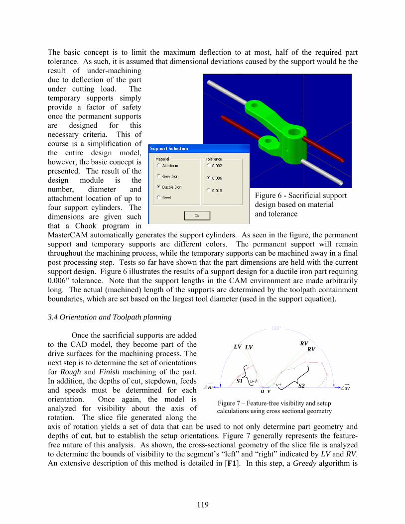
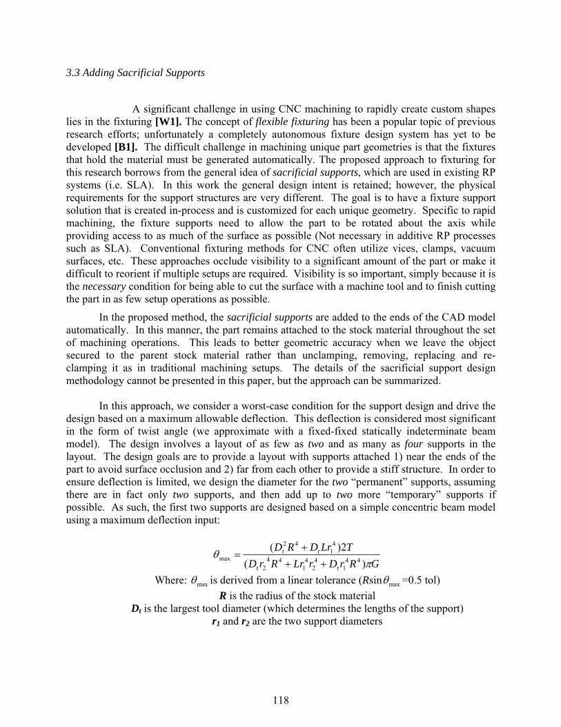
The basic concept is to limit the maximum deflection to at most, half of the required part tolerance. As such, it is assumed that dimensional deviations caused by the support would be the result of under-machining due to deflection of the part under cutting load. The temporary supports simply provide a factor of safety once the permanent supports are designed for this necessary criteria. This of course is a simplification of the entire design model, however, the basic concept is presented. The result of the design module is the number, diameter and attachment location of up to four support cylinders. The dimensions are given such that a Chook program in MasterCAM automatically generates the support cylinders. As seen in the figure, the permanent support and temporary supports are different colors. The permanent support will remain throughout the machining process, while the temporary supports can be machined away in a final post processing step. Tests so far have shown that the part dimensions are held with the current support design. Figure 6 illustrates the results of a support design for a ductile iron part requiring 0.006” tolerance. Note that the support lengths in the CAM environment are made arbitrarily long. The actual (machined) length of the supports are determined by the toolpath containment boundaries, which are set based on the largest tool diameter (used in the support equation). 3.4 Orientation and Toolpath planning Once the sacrificial supports are added to the CAD model, they become part of the drive surfaces for the machining process. The next step is to determine the set of orientations for Rough and Finish machining of the part. In addition, the depths of cut, stepdown, feeds and speeds must be determined for each orientation. Once again, the model is analyzed for visibility about the axis of rotation. The slice file generated along the axis of rotation yields a set of data that can be used to not only determine part geometry and depths of cut, but to establish the setup orientations. Figure 7 generally represents the feature-free nature of this analysis. As shown, the cross-sectional geometry of the slice file is analyzed to determine the bounds of visibility to the segment’s “left” and “right” indicated by LV and RV. An extensive description of this method is detailed in [F1]. In this step, a Greedy algorithm is
Figure 6 - Sacrificial support design based on material and tolerance
Figure 7 – Feature-free visibility and setup calculations using cross sectional geometry
LVLV RVRV
vuv+
u-1vu∠ uv∠
S1S2
119
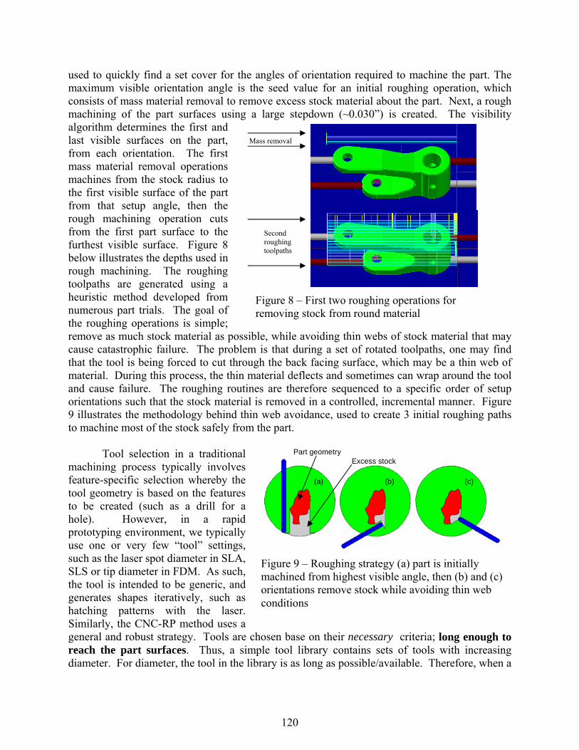
used to quickly find a set cover for the angles of orientation required to machine the part. The maximum visible orientation angle is the seed value for an initial roughing operation, which consists of mass material removal to remove excess stock material about the part. Next, a rough machining of the part surfaces using a large stepdown (~0.030”) is created. The visibility algorithm determines the first and last visible surfaces on the part, from each orientation. The first mass material removal operations machines from the stock radius to the first visible surface of the part from that setup angle, then the rough machining operation cuts from the first part surface to the furthest visible surface. Figure 8 below illustrates the depths used in rough machining. The roughing toolpaths are generated using a heuristic method developed from numerous part trials. The goal of the roughing operations is simple; remove as much stock material as possible, while avoiding thin webs of stock material that may cause catastrophic failure. The problem is that during a set of rotated toolpaths, one may find that the tool is being forced to cut through the back facing surface, which may be a thin web of material. During this process, the thin material deflects and sometimes can wrap around the tool and cause failure. The roughing routines are therefore sequenced to a specific order of setup orientations such that the stock material is removed in a controlled, incremental manner. Figure 9 illustrates the methodology behind thin web avoidance, used to create 3 initial roughing paths to machine most of the stock safely from the part. Tool selection in a traditional machining process typically involves feature-specific selection whereby the tool geometry is based on the features to be created (such as a drill for a hole). However, in a rapid prototyping environment, we typically use one or very few “tool” settings, such as the laser spot diameter in SLA, SLS or tip diameter in FDM. As such, the tool is intended to be generic, and generates shapes iteratively, such as hatching patterns with the laser. Similarly, the CNC-RP method uses a general and robust strategy. Tools are chosen base on their necessary criteria; long enough to reach the part surfaces. Thus, a simple tool library contains sets of tools with increasing diameter. For diameter, the tool in the library is as long as possible/available. Therefore, when a
Mass removal
Second roughing toolpaths
Figure 8 – First two roughing operations for removing stock from round material
Part geometry Excess stock
(a) (b) (c)
Figure 9 – Roughing strategy (a) part is initially machined from highest visible angle, then (b) and (c) orientations remove stock while avoiding thin web conditions
120
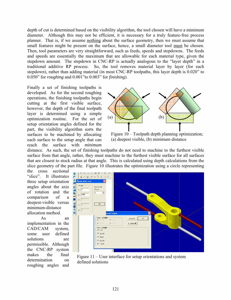
depth of cut is determined based on the visibility algorithm, the tool chosen will have a minimum diameter. Although this may not be efficient, it is necessary for a truly feature-free process planner. That is, if we assume nothing about the surface geometry, then we must assume that small features might be present on the surface, hence, a small diameter tool must be chosen. Then, tool parameters are very straightforward, such as feeds, speeds and stepdowns. The feeds and speeds are essentially the maximum that are allowable for each material type, given the stepdown amount. The stepdown in CNC-RP is actually analogous to the “layer depth” in a traditional additive RP process. So, the tool removes material layer by layer (for each stepdown), rather than adding material (in most CNC-RP toolpaths, this layer depth is 0.020” to 0.050” for roughing and 0.001”to 0.003” for finishing). Finally a set of finishing toolpaths is developed. As for the second roughing operations, the finishing toolpaths begin cutting at the first visible surface, however, the depth of the final toolpath layer is determined using a simple optimization routine. For the set of setup orientation angles defined for the part, the visibility algorithm sorts the surfaces to be machined by allocating each surface to the setup angle that can reach the surface with minimum distance. As such, the set of finishing toolpaths do not need to machine to the furthest visible surface from that angle, rather, they must machine to the furthest visible surface for all surfaces that are closest to stock radius at that angle. This is calculated using depth calculations from the slice geometry of the part file. Figure 10 illustrates the optimization using a circle representing the cross sectional “slice”. It illustrates three setup orientation angles about the axis of rotation and the comparison of a deepest-visible versus minimum-distance allocation method.
As an implementation in the CAD/CAM system, some user defined solutions are permissible. Although the CNC-RP system makes the final determination on roughing angles and
(a) (b)
Figure 10 – Toolpath depth planning optimization; (a) deepest visible, (b) minimum distance
Figure 11 – User interface for setup orientations and system defined solutions
121
settings, the user can force certain setup directions into the finishing set. Therefore, the greedy algorithm will consider the user’s input as forced solutions, and then optimize based on that reduced set (those surfaces in the set not covered by the user-defined angles). This method is employed because the user may wish to select some angle (perhaps one that aligns with a desired feature) that they believe is a required or good angle. Figure 11 illustrates a simple user interface, and then the solution as derived by the system. In this case, the user forces 0 and 180 degrees into the solution, then the greedy algorithm finds three additional angles for the set cover.
It should be noted that the toolpaths generated for both rough and finish machining are
generated from the original CAD model of the part, as imported into the CAD/CAM system. Therefore, the toolpaths in CNC-RP are not based on an STL file, rather, from the native surface geometry. Although STL models of the part are used throughout the analysis of the geometry (for setup angles, supports and toolpath parameters), the actually toolpath generation programs are always run on the accurate part surface. In this manner, CNC-RP avoids the inherent approximation errors of additive processes which derive their toolpaths from the STL model. 4. Examples
The steps of the process described in the previous section result in a concatenated set of NC code and a setup sheet. The setup sheet lists the tools required and their tool changer locations, and the diameter and length of the stock material. In order to run the part program, the user simply loads the material and NC code an initiates a cycle-start.
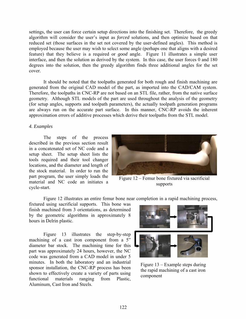
Figure 12 illustrates an entire femur bone near completion in a rapid machining process,
fixtured using sacrificial supports. This bone was finish machined from 3 orientations, as determined by the geometric algorithms in approximately 8 hours in Delrin plastic.
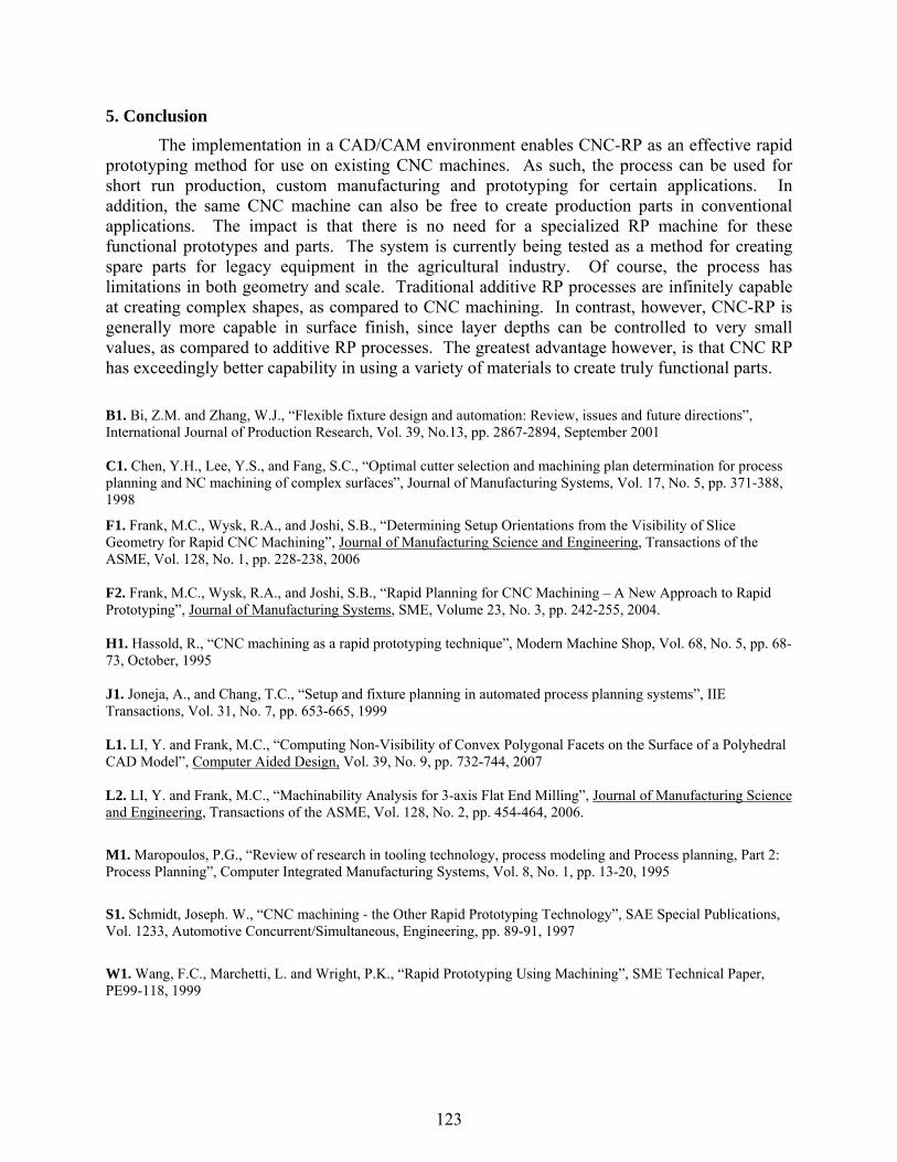
Figure 13 illustrates the step-by-step machining of a cast iron component from a 5” diameter bar stock. The machining time for this part was approximately 24 hours, however, the NC code was generated from a CAD model in under 5 minutes. In both the laboratory and an industrial sponsor installation, the CNC-RP process has been shown to effectively create a variety of parts using functional materials ranging from Plastic, Aluminum, Cast Iron and Steels.
Figure 12 – Femur bone fixtured via sacrificial supports
Figure 13 – Example steps during the rapid machining of a cast iron component
122
5. Conclusion
The implementation in a CAD/CAM environment enables CNC-RP as an effective rapid prototyping method for use on existing CNC machines. As such, the process can be used for short run production, custom manufacturing and prototyping for certain applications. In addition, the same CNC machine can also be free to create production parts in conventional applications. The impact is that there is no need for a specialized RP machine for these functional prototypes and parts. The system is currently being tested as a method for creating spare parts for legacy equipment in the agricultural industry. Of course, the process has limitations in both geometry and scale. Traditional additive RP processes are infinitely capable at creating complex shapes, as compared to CNC machining. In contrast, however, CNC-RP is generally more capable in surface finish, since layer depths can be controlled to very small values, as compared to additive RP processes. The greatest advantage however, is that CNC RP has exceedingly better capability in using a variety of materials to create truly functional parts.
B1. Bi, Z.M. and Zhang, W.J., “Flexible fixture design and automation: Review, issues and future directions”, International Journal of Production Research, Vol. 39, No.13, pp. 2867-2894, September 2001 C1. Chen, Y.H., Lee, Y.S., and Fang, S.C., “Optimal cutter selection and machining plan determination for process planning and NC machining of complex surfaces”, Journal of Manufacturing Systems, Vol. 17, No. 5, pp. 371-388, 1998
F1. Frank, M.C., Wysk, R.A., and Joshi, S.B., “Determining Setup Orientations from the Visibility of Slice Geometry for Rapid CNC Machining”, Journal of Manufacturing Science and Engineering, Transactions of the ASME, Vol. 128, No. 1, pp. 228-238, 2006
F2. Frank, M.C., Wysk, R.A., and Joshi, S.B., “Rapid Planning for CNC Machining – A New Approach to Rapid Prototyping”, Journal of Manufacturing Systems, SME, Volume 23, No. 3, pp. 242-255, 2004.
H1. Hassold, R., “CNC machining as a rapid prototyping technique”, Modern Machine Shop, Vol. 68, No. 5, pp. 68-73, October, 1995 J1. Joneja, A., and Chang, T.C., “Setup and fixture planning in automated process planning systems”, IIE Transactions, Vol. 31, No. 7, pp. 653-665, 1999 L1. LI, Y. and Frank, M.C., “Computing Non-Visibility of Convex Polygonal Facets on the Surface of a Polyhedral CAD Model”, Computer Aided Design, Vol. 39, No. 9, pp. 732-744, 2007 L2. LI, Y. and Frank, M.C., “Machinability Analysis for 3-axis Flat End Milling”, Journal of Manufacturing Science and Engineering, Transactions of the ASME, Vol. 128, No. 2, pp. 454-464, 2006.
M1. Maropoulos, P.G., “Review of research in tooling technology, process modeling and Process planning, Part 2: Process Planning”, Computer Integrated Manufacturing Systems, Vol. 8, No. 1, pp. 13-20, 1995
S1. Schmidt, Joseph. W., “CNC machining - the Other Rapid Prototyping Technology”, SAE Special Publications, Vol. 1233, Automotive Concurrent/Simultaneous, Engineering, pp. 89-91, 1997
W1. Wang, F.C., Marchetti, L. and Wright, P.K., “Rapid Prototyping Using Machining”, SME Technical Paper, PE99-118, 1999
123
![Rapid Manufactured Textilesedge.rit.edu/edge/P10551/public/SFF/SFF 2006 Proceedings...manufacture of end-use components without the application of conventional tooling [3]. Utilising](https://img.pdfslide.net/doc/110x75/602d3c0f1f981863c1164494/rapid-manufactured-2006-proceedings-manufacture-of-end-use-components-without.jpg)


![Implementing Rapid Prototyping Using CNC Machining (CNC …edge.rit.edu/content/P10551/public/SFF/SFF 2007...cutting tool in order to create the surfaces (toolpath planning) [M1,C1,J1]](https://img.pdfslide.net/doc/110x75/603c7a50462a6121fb60dec6/implementing-rapid-prototyping-using-cnc-machining-cnc-edgeriteducontentp10551publicsffsff.jpg)