Embed Size (px)
Citation preview
TW2000 WOOD-FIRED BOILER
OWNER’S MANUAL
IMPORTANT
READ OWNER’S MANUAL THOROUGHLY BEFORE INSTALLING BOILER OR LIGHTING FIRE.
CONSULT LOCAL AUTHORITIES IF IN DOUBT ABOUT YOUR LOCAL FIRE SAFETY REGULATIONS.
ALL INSTALLATIONS MUST BE MADE IN ACCORDANCE WITH LOCAL AND STATE OR
PROVINCIAL CODES WHICH MAY DIFFER FROM THIS MANUAL.
IMPROPER INSTALLATION WILL RESULT IN VOIDING OF WARRANTY.

TW2000 WOOD-FIRED BOILER – INSTRUCTION MANUAL
TW2000 10/6/05
1
CONTENTS
SECTION 1 – OPERATING INSTRUCTIONS Pg. Specifications 2 1.1 Introduction 3 1.2 Wood-Burning 3 1.3 Storage of Wood 4 1.4 Maximum Solid-Fuel Charge 5 1.5 Maintenance 5 1.5.1 Cleaning 5 1.6 Safety 6 1.7 Electrical Power Failure 6 1.8 Homeowner Checklist 7 SECTION 2 INSTALLATION 2.1 Introduction 9 2.2 Uncrating 9 2.3 Locating the Boiler 10 2.4.1 Combustion Air Supply 11
2.4.2 Flue Pipe and Chimney 11 2.5 Clearances 13 2.6 Plumbing Connection 13
2.6.1 Free Standing 13 2.6.2 Parallel Piping System 14
2.7 Control System 14 2.8 Wiring 15 2.9 Dealer Instructions to Homeowner 15 2.10 Installers Checklist 15
Parts List TW-2000 Parallel Plumbing Wiring Explanation
DIAGRAMS TW – 1 Parallel Piping Diagram TW – 1EH Parallel Piping Electric Boiler TW – 2 Parallel Wiring Diagram
TW – 3 Alternate Parallel Wiring Diagram TW – 3EH Wiring Diagram Electric Boiler
TW – 4 Free Standing Piping Diagram TW – 5 Free Standing Wiring Diagram TW – 6 Alternate Free Standing Wiring Diagram TW – 7 Heat Exchanger
TW – 8 Non-Combustible Floor Base TW – 9 Accessory Layouts TW – 10 Damper Motor Installation TW – 11 USA Models – Fusible Plug
TW2000 WOOD-FIRED BOILER – INSTRUCTION MANUAL
TW2000 10/6/05
2
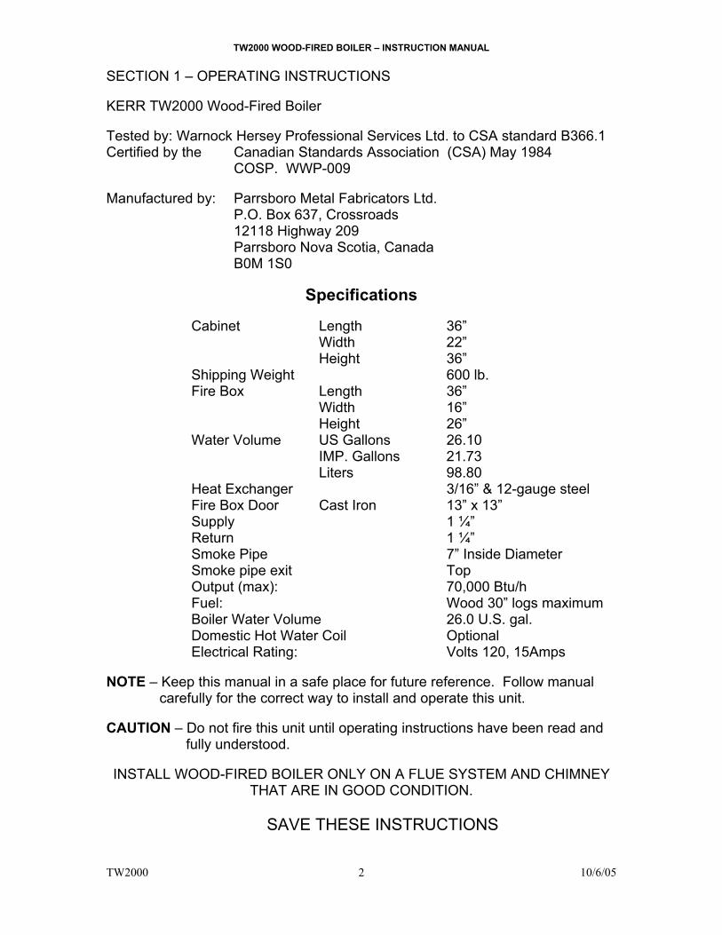
SECTION 1 – OPERATING INSTRUCTIONS KERR TW2000 Wood-Fired Boiler Tested by: Warnock Hersey Professional Services Ltd. to CSA standard B366.1 Certified by the Canadian Standards Association (CSA) May 1984
COSP. WWP-009 Manufactured by: Parrsboro Metal Fabricators Ltd.
P.O. Box 637, Crossroads 12118 Highway 209 Parrsboro Nova Scotia, Canada B0M 1S0
Specifications
Cabinet Length 36”
Width 22” Height 36”
Shipping Weight 600 lb. Fire Box Length 36” Width 16” Height 26” Water Volume US Gallons 26.10 IMP. Gallons 21.73 Liters 98.80 Heat Exchanger 3/16” & 12-gauge steel Fire Box Door Cast Iron 13” x 13” Supply 1 ¼” Return 1 ¼” Smoke Pipe 7” Inside Diameter Smoke pipe exit Top Output (max): 70,000 Btu/h Fuel: Wood 30” logs maximum Boiler Water Volume 26.0 U.S. gal. Domestic Hot Water Coil Optional Electrical Rating: Volts 120, 15Amps
NOTE – Keep this manual in a safe place for future reference. Follow manual
carefully for the correct way to install and operate this unit. CAUTION – Do not fire this unit until operating instructions have been read and
fully understood.
INSTALL WOOD-FIRED BOILER ONLY ON A FLUE SYSTEM AND CHIMNEY THAT ARE IN GOOD CONDITION.
SAVE THESE INSTRUCTIONS
TW2000 WOOD-FIRED BOILER – INSTRUCTION MANUAL
TW2000 10/6/05
3
SECTION 1 – OPERATING INSTRUCTIONS 1.1 Introduction Congratulations on your purchase of the KERR TW2000 Wood-Fired Boiler. Developed in Atlantic Canada, this KERR Boiler has been designed to allow you to heat your home with wood, one of North America’s most abundant fuels. The heat exchanger materials meet ASME (American Society of Mechanical Engineers) requirements for domestic boilers. Designed with you in mind, the KERR TW2000 Wood-Fired Boiler will provide you with many years of safe, efficient central heating. To ensure you have a clear understanding of the operating procedures of this boiler, please take the time to read the remainder of this section on operating procedures. If you have any questions, your KERR DEALER will be happy to answer them for you. 1.2 Wood-Burning The TW2000 Wood-Fired Boiler will burn most wood fuels, however it is recommended that only dry seasoned hardwood be used as much as possible since it affords cleaner, safer and more efficient operation. Burning seasoned hardwood will leave less ash, soot and creosote residue and will require fueling less often. Use smaller loads of wood on warmer days.
WARNING: DO NOT use chemicals or fluids to start the fire or during operation.
DO NOT burn driftwood or manufactured logs (compressed wood). Before adding fuel to an existing fire turn up the thermostat for about five minutes or lift damper chain to hold damper fully open for about one minute before opening the loading door. This action will allow residual smoke to clear from the combustion chamber and reduce smoke entering the basement during refueling. Twice daily refueling may be sufficient in modern well-insulated homes. However, KERR recommends that small fuel loads be added morning, noon and early evening and late evening, rather than large quantities infrequently. A small intense fire will burn more efficiently than a large smoldering fire in the TW2000 Wood-Fired Boiler and will produce less creosote. When refueling the TW2000, the remaining coals should be raked to the front of the combustion chamber before adding any new fuel. New fuel shall be placed on and behind the hot coals. This will help create a more even and efficient burn. The TW2000 owner should attempt to gauge fuel quantities with outdoor temperatures; a little practice will provide greater satisfaction and efficiency. WARNING: This Boiler is not to be used with an automatic stoker. Keep firing door tightly closed and maintain door seal in good condition.

TW2000 WOOD-FIRED BOILER – INSTRUCTION MANUAL
TW2000 10/6/05
4
IN CASE A SERIOUS CREOSOTE FIRE BEGINS: a) Close the damper door by disconnecting chain b) Close all draft regulators c) Throw ½ lb, of coarse or table salt on the fire and reclose door immediately. d) Call the FIRE DEPARTMENT at once! Have a firmly established Emergency Procedure in place for the handling of a flue fire. CREOSOTE Wood combustion is never 100% complete. Wood smoke always contains some unburned gases and a mixture of unburned tar-like liquids. A percentage of these materials will condense out on any cool surface, leaving a dark brown or black substance with an unpleasant acrid odour. This substance is commonly called creosote. If these wood gases condense out on cool surfaces such as a cold chimney or a long smoke pipe they retain large amounts of water and will be very fluid. At higher temperatures the condensed creosote will resemble tar (thick and tacky). Creosote generation is highest during low heat outputs common with long smoldering burns. Creosote generation is lowest during high heat outputs common with intense fires. It is recommended that a small intense fire be used for best results against creosote build up even though the Wood-Fired Boiler will require refueling more often. Creosote generation is also higher when burning green wood. The moisture in the green wood absorbs the heat from the fire, cooling the fire below the point at which the creosote can be consumed. The low temperature smoke is then further cooled in the upper boiler chamber; smoke pipe and chimney allowing large amounts of creosote to form. To reduce creosote build-up during periods of low heat requirements (i.e Spring and Fall) it is recommended to fuel the Wood-Fired Boiler with smaller quantities of smaller diameter logs. Matching fuel loads and heat requirements will result in cleaner combustion and higher efficiency. 1.3 Storage of Wood Once cut, green wood dries (or seasons), quickly at first and then at a slower rate. When the wood has been cut to the proper length and split, it should be piled outside during the summer months. Place two poles on the ground to serve as rails to keep the firewood off the moist ground. Stack the wood so that both ends of the logs are exposed to the air if space is available, since more drying occurs through the cut ends than through the sides. This is true even with wood that has been split. The woodpile should be under cover so that it will not absorb moisture from the rain and snow before it is used, but still open on the sides and ends to the drying effect of the wind and sun. Store wood in neat, well-supported piles.
TW2000 WOOD-FIRED BOILER – INSTRUCTION MANUAL
TW2000 10/6/05
5
DO NOT store wood within installation clearances or within the space required for charging or ash removal.
1.4 Maximum Solid-Fuel Charge The maximum level for a solid-fuel charge is the middle of the loading door, or the level of the handle. DO NOT overfill or extreme over-heating may result, causing warpage or damage to the boiler.
The KERR TW2000 Wood-Fired Boiler will accept whole or split logs up to 34 in. (864 mm) long, but a 30 in. (762 mm) log length is recommended for convenience and ease in handling.
Maximum damper gate opening is 11/16”. Do not tamper or adjust to greater opening in an attempt to increase fire or over-firing and hazard may result. 1.5 Maintenance Some regular maintenance is necessary on the KERR TW2000 boiler. A good practice is to establish a routine for the storage of fuel, care of the appliance, and firing techniques. 1.5.1 Cleaning The KERR TW2000 Wood-Fired Boiler must be cleaned regularly to maintain top efficiency. The boiler needs cleaning more often when burning green wood, or during long periods of low fire. When the KERR TW2000 Wood-Fired Boiler is first installed the boiler heat exchanger should be checked visually from the firebox and smoke pipe hole every week to determine the rate at which creosote or ash is accumulating within the Boiler. Cleaning should be done whenever there is more than ¼ inch of build-up on the heat exchanger or 3 inches of ash in the base. CLEANING PROCEDURE: (1) Make sure fire is completely out and the Boiler has cooled. (2) Remove the smoke pipe located on the top of the Boiler. (3) Remove the overhead baffle in the combustion chamber if necessary. (4) The heat exchanger is now accessible for cleaning. (5) Use the scraper provided to remove all soot and ash from the boiler heat
exchanger and exposed surfaces. (6) Always check flue pipe for creosote or ash build-up in the pipe and clean if
necessary. (7) Reinstall smoke pipe making sure that all joints are secured with at least 3
sheet metal screws. Also reinstall the overhead baffle. (8) Check chimney cleanout for ash build-up and remove any accumulation.
TW2000 WOOD-FIRED BOILER – INSTRUCTION MANUAL
TW2000 10/6/05
6
(9) Residue may be removed from the firebox or left to be burned during the next fire. It is good practice to leave a layer of ash approximately one inch deep in the base of the firebox.
DISPOSAL OF ASHES Ashes should be placed in a metal container with a tight fitting lid. The closed container of ashes should be placed on a non-combustible floor or on the ground, well away from all combustible materials, pending final disposal. If the ashes are disposed of by burial in soil or otherwise locally dispersed, they should be retained in the closed container until all cinders have thoroughly cooled. WARNING – Ashes usually contain live dormant coals, which may burn for many hours after a recognizable flame has disappeared. Use extreme caution when handling and disposing ashes. IMPORTANT – No other waste shall be placed in this container. 1.6 Safety If the boiler overheats due to improper operation the following precautions should be taken: (1) DO NOT shut off power. The circulation pump must be kept running to
disperse excessive heat. (2) Manually close the damper door by unhooking the chain. (3) Increase all thermostats in the house to maximum to help disperse
excessive heat. (4) Excessive heat caused by extreme over-firing or a control malfunction
may cause the relief valve to blow off water/steam into the firebox. Do not be alarmed. The relief valve will reseat when the excessive pressure has been released.
(5) Do not add more fuel until you are certain that all controls are functioning properly and no damage has been done to the boiler.
WARNING – The maximum opening of the combustion air damper is preset at
the factory. DO NOT adjust the stop or attempt to increase the combustion air by any means.
TW2000 WOOD-FIRED BOILER – INSTRUCTION MANUAL
TW2000 10/6/05
7
1.7 Electrical Power Failure
If no one is home during a power failure, the safety bypass zone valve will automatically open and some gravity heating will take place. The damper door will automatically close, but combustion air will continue to enter through the secondary air holes and a fire should be maintained. For optimum heating during a power failure follow the procedure listed below:
(1) Manually open all zone valves and flow check valves to allow
gravity flow to all areas. (Check with your installer)
(2) Place a coin under the damper flap in such a way that it will fall clear when power is restored and the damper motor operates.
(3) Maintain a careful watch on the boiler water temperature. If it
should exceed 200º F (95º C) close the damper door.
(4) Do not leave the boiler unattended in this position.
(5) Refuel frequently with a small load to maintain a small fire at ½ normal maximum volume.
(6) Do not expect to maintain maximum comfort under no power
conditions.
(7) Do not allow anyone who is unfamiliar with the operation of the Boiler to attend it during a power failure.
TW2000 WOOD-FIRED BOILER – INSTRUCTION MANUAL
TW2000 10/6/05
8
1.8 HOMEOWNER CHECKLIST (a) Keep area around TW2000 boiler clean and clear of combustibles. (b) Use only dry wood. DO NOT burn garbage, gasoline, naphtha
engine oil or any other combustible liquid.
(c) Remove ashes as directed.
(d) Watch for soot in smoke pipe – clean regularly.
(e) Clean Boiler heat exchanger regularly.
(f) Be aware of danger due to overfiring unit.
(g) Do not load above maximum loading level (middle of loading door) or overheating may result.
(h) This unit is NOT suitable for automatic stoking.
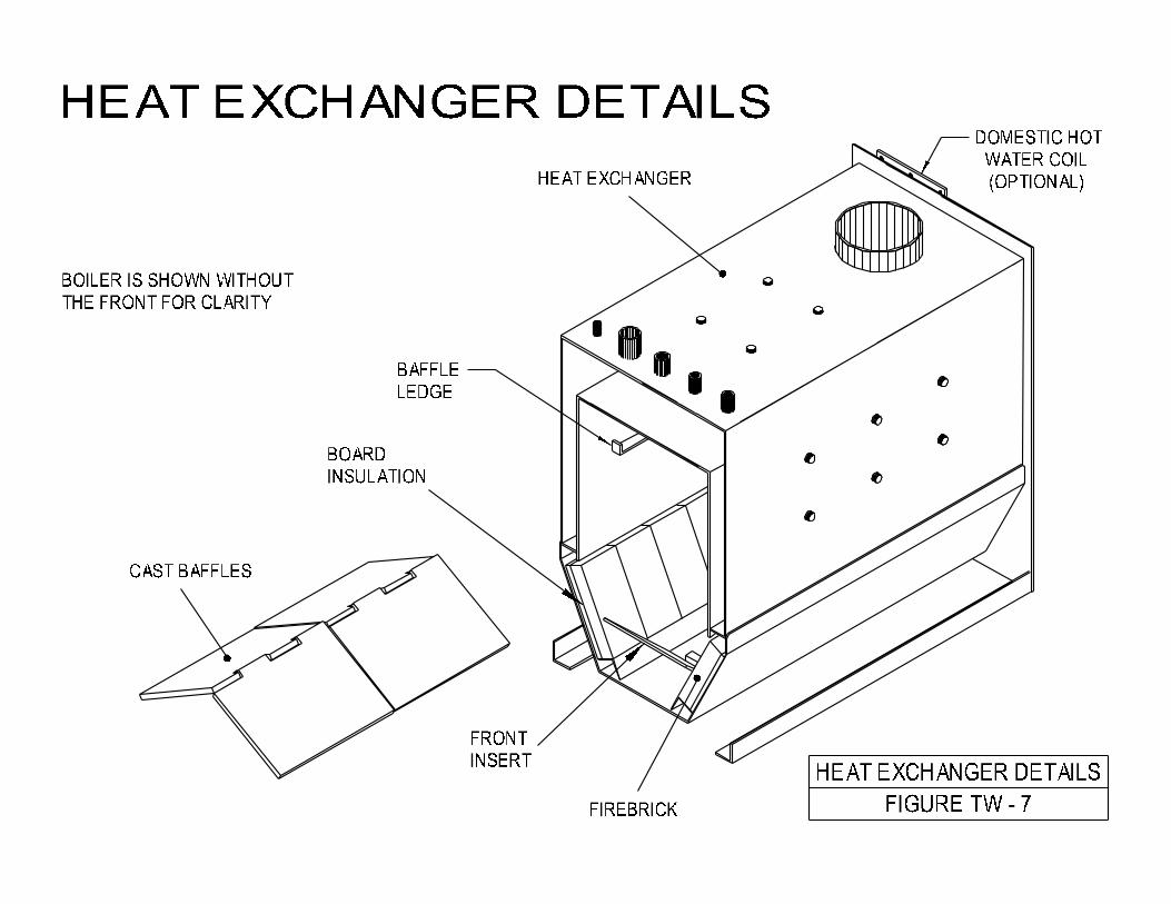
(i) Load carefully. Do not slam fuel against rear or sides of firebox.
This may damage the brick lining. See fig. TW-7 to order and install replacement firebrick.
(j) Always observe the following minimum clearances to combustible
materials – Front 48” (1220 mm); one side 6” (152 mm); opposite side and rear 24” (610 mm); and flue pipe 18” (465 mm) and the floor must be non-combustible.
(k) Do not store solid fuel within the above clearances or within the
space required for charging and ash removal.
(l) Keep firing door closed and maintain seals in good condition.
(m) Establish a routine for storage of fuel, care of the appliance, and firing techniques.

TW2000 WOOD-FIRED BOILER – INSTRUCTION MANUAL
TW2000 10/6/05
9
SECTION 2 INSTALLATION INSTRUCTIONS
TW2000 WOOD-FIRED BOILER – INSTRUCTION MANUAL
TW2000 10/6/05
10
SECTION 2 – INSTALLATION INSTRUCTIONS
2.1 Introduction to Installers
Before installing this KERR TW2000 Wood-Fired Boiler, please read the following instruction manual carefully. This unit is designed to be a freestanding central heating boiler, or as an add-on to operate in conjunction with an existing oil, gas, or electric unit, to provide complete central heating in medium sized well-insulated homes. Before installing be sure unit is properly sized for the intended application. Warranty does not cover misapplication of unit.
Applicable Standards The KERR TW2000 Wood-Fired Boiler must be installed in accordance with the requirements of the National Fire Protection Association codes, the Canadian Heating, Ventilation and Air Conditioning Code, The National Board of Fire Underwriters, and the C.S.A. Standards for solid fuel burning equipment as outlined in B365-01. In all cases consult your local authorities and fire insurance company for specific regulations. 2.2 Uncrating
When you receive your TW2000 Wood-Fired Boiler, check it carefully to ensure that all components are present and in good condition. If there has been any damage or loss in transportation, please notify the carrier and retailer at once. NOTE: Some parts may be packed inside boiler firebox. Inspect for the following:
1. Firebox/Heat exchanger 2. Poker/Coals rake 3. Cabinet 4. Barometric damper 5. Firebrick (Factory installed in base) See fig. TW-7 for detail. 6. Front insert 7. Overhead baffle 8. Cast door handle assembly 9. Controls package 10. Optional domestic hot water coil
Control Package includes:
1. Dual aquastat, ½” well 2. Single aqustat wt well ½” 3. Damper Motor 4. N/O Zone valve, and fittings 5. Pressure relief valve 6. Tridicator 7. Transformer 120/24V 8. Wiring Harness and Parts 9. Black iron and copper fittings

TW2000 WOOD-FIRED BOILER – INSTRUCTION MANUAL
TW2000 10/6/05
11
2.3 Locating the Boiler
The location of the Boiler must be as close as possible to the tile-lined brick chimney, or factory-built solid-fuel approved chimney (ULC S629). Keep in mind also the day-to-day operation, and place for ease of fueling and cleaning. To lighten the boiler for placement, all parts including firebrick and baffles can be removed. It is important to provide adequate combustion air to the Boiler. It may be necessary to add a ventilator to an exterior wall of a closed Boiler room or an airtight basement.
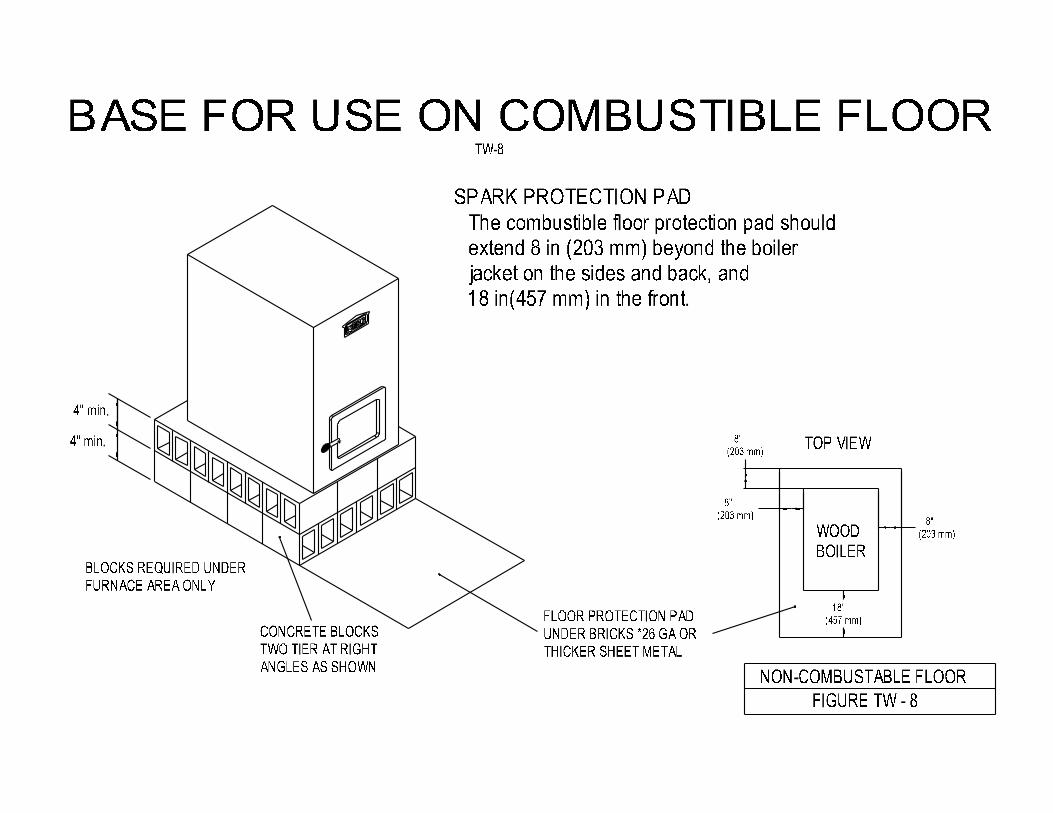
The Boiler must be installed so that the clearances on page 13, or those of local authorities are met. If the Boiler must be installed on a combustible floor, a non-combustible base must be built as shown in Figure TW - 8. Two layers of hollow masonry block (4” thick) are placed at right angles to each other so that the ventilation holes of one layer are opposite to those of the other layer. Also for ember protection, there must be a minimum one layer of 26 ga. galvanized metal beneath the masonry blocks. This base must extend beyond the Boiler to a minimum distance of 18 in (457 mm) in front and 8 in. (204 mm) on all sides. With the location of the boiler selected the next step is to position the unit and proceed with assembly. If a noncombustible base is not required Kerr recommends that the boiler be placed on masonry blocks (bricks or 8”concrete blocks) if space permits, to allow easier fueling and to keep the KERR TW2000 boiler above any possible water in the basement. These blocks should extend approximately 1” on all sides of the boiler to support the cabinet. Continue as follows:
1. Plan all plumbing and electrical runs so that flue pipe is easily removable for cleaning and to permit movement in the area as necessary.
2. Position masonry blocks and place the unit on top. Level the blocks as necessary.
3. Install the domestic coil if it is to be used, after removing the blank plate.
4. Set the loading door in place on the hinges. 5. Install aquastat wells, tridicator and pipe fittings using good quality pipe
thread sealant or Teflon tape (Fig. TW-9). 6. Set each side panel in place with bottom of panel hooking over boiler
base rail angle. Top fits down over sides and boiler. A perfect fit may be attained without any retaining screws.
7. Install the draft damper motor using the mounting holes provided, and connect the chain to the damper and to the damper motor wheel. Leave the bottom chain link open so that it may be disconnected in an emergency.
TW2000 WOOD-FIRED BOILER – INSTRUCTION MANUAL
TW2000 10/6/05
12
8. Adjust chain length by squeezing or expanding links with pliers. Adjust the chain so that the damper is open to the maximum of 11/16” without putting any extra strain on the damper motor.
9. Install the aquastats and complete the wiring, plumbing, smoke pipe and fire extinguishing tube installations as shown in the appropriate electrical and plumbing diagrams.
10. IMPORTANT: Always test all functions under actual firing conditions before leaving the site. Test especially for correct operation of damper, limit and by-pass zone valve and circulator.
Note: If the KERR TW2000 boiler is installed above the radiation level, a low water cut off is required. It should be installed on pipe tees positioned at the supply and return points of the boiler.
Never leave start up to the homeowner. Explain the operations thoroughly to the operator.
2.4.1 Combustion Air Supply Air inlets of at least 200 square inches free area (1.5 in2/1000Btu) must be provided to the room occupied by the wood fired or oil fired boiler. These fresh air inlets must provide or allow free access of fresh outside air to the boiler. At no time, or under any circumstances can a wood or oil burning appliance, be starved of combustion air.
The appliance must at all times be able to maintain the approved stack draft. The barometric draft regulator must be installed on the boiler smoke pipe in the same room or at least in such a way that there is unrestricted free passage of air between the combustion air inlet to the boiler or burner and the barometric draft regulator.
It is important to provide adequate combustion air to the boiler. It may be necessary to add a ventilator to an exterior wall of a closed boiler room or an airtight basement.
Operating a wood or oil fired appliance with inadequate combustion air could be hazardous.

TW2000 WOOD-FIRED BOILER – INSTRUCTION MANUAL
TW2000 10/6/05
13
2.4.2 Flue Pipe and Chimney The Boiler must be located to meet a minimum venting distance needed between the Boiler and the flue. It should also be ducted so that there is a minimum number of elbows used. The flue pipe must be installed with a gradual rise of ½” or more per foot from the Boiler to the flue.
NEVER ALLOW THE SMOKE PIPE TO RUN DOWNHILL TO THE FLUE!
The smoke pipe and chimney must be at least 7 inches in diameter. The flue pipe or a chimney may be of different cross-sectional area than that of the appliance smoke pipe, provided that sufficient draft is available at the appliance. Space must be provided around the smoke pipe and the back of the Boiler to allow easy access for the purpose of cleaning. Smoke pipes must not be lighter than 24 gauge black steel. All flue pipe must be securely fastened with at least 3 sheet metal screws at every joint, and properly supported.
Always meet or exceed flue pipe clearance specifications - 18” clearance from flue pipe to combustibles in all directions.
Connect the boiler only to an approved chimney suitable for solid fuel appliances and capable of venting the products of combustion. The chimney must be installed with proper clearances above roof and from adjacent structures and trees. If a masonry chimney is used it must be in good condition and be equipped with a tile liner. Flue thimble or flue pipe must not extend into the chimney flue, as it will reduce the draft.
Connect only to a flue or chimney capable of maintaining a negative draft of between .02”w.c. min. and .05”w.c. max., at all times and conditions. To maintain this draft, one or two draft regulators may be required. We recommend that the KERR TW2000 Wood-Fired Boiler be connected to its own chimney. However, two or more fuel fired appliances, other than fireplaces or incinerators, may be connected to the same chimney.
TW2000 WOOD-FIRED BOILER – INSTRUCTION MANUAL
TW2000 10/6/05
14
The National Standard of Canada, Installation Code for Solid-Fuel-Burning Appliances and Equipment, CSA-B365-01 clause 5.2.9 states that:
Two or more appliances shall not be connected to the same chimney flue unless:
a. The appliances are located on the same story; b. A negative pressure is maintained at the flue collar of each
appliance; c. Each appliance is provided with a means to control the rate of flow
of air or flue gases through the appliance combustion and heat exchanger chambers. Where limitations on flue pressure (draft) are contained in the manufacturer’s instructions, such means shall be capable of maintaining at the flue collar, the pressure specified by the appliance manufacture; NOTE: For the purpose of this Clause, draft controls include ash pit air control dampers, dampers or draft slides wherever located, over fire and flue key pipe dampers, and check draft controls located on or in the flue pipe.
d. The flue pipes of the appliances are connected to a manifold as close to the chimney as practicable or directly to the chimney in the following order: (i) If only solid fuel is used, the flue pipe from the smallest
appliance shall be on top (downstream); (ii) If different fuels are used as permitted in Clause 5.2.7, the oil
flue pipe shall be on top (downstream); and the solid fuel flue pipe on the bottom (upstream); and
e. The chimney flue is capable of venting the flue gas by natural draft when all appliances not interlocked to prevent simultaneous firing are firing at their maximum rate at the same time.
WARNING: If this setting is exceeded it could cause a solid fuel fire to burn out of control. When installing a wood-burning appliance to an existing chimney carefully inspect entire chimney for the presence of old inlet holes, which may be improperly covered by metal caps or other unacceptable means. Fill any openings with brick and mortar to ensure no hazardous openings exist.
TW2000 WOOD-FIRED BOILER – INSTRUCTION MANUAL
TW2000 10/6/05
15
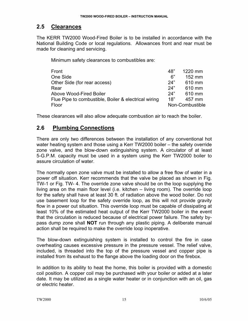
2.5 Clearances
The KERR TW2000 Wood-Fired Boiler is to be installed in accordance with the National Building Code or local regulations. Allowances front and rear must be made for cleaning and servicing.
Minimum safety clearances to combustibles are: Front 48” 1220 mm One Side 6” 152 mm Other Side (for rear access) 24” 610 mm Rear 24” 610 mm Above Wood-Fired Boiler 24” 610 mm Flue Pipe to combustible, Boiler & electrical wiring 18” 457 mm Floor Non-Combustible
These clearances will also allow adequate combustion air to reach the boiler. 2.6 Plumbing Connections There are only two differences between the installation of any conventional hot water heating system and those using a Kerr TW2000 boiler – the safety override zone valve, and the blow-down extinguishing system. A circulator of at least 5-G.P.M. capacity must be used in a system using the Kerr TW2000 boiler to assure circulation of water.
The normally open zone valve must be installed to allow a free flow of water in a power off situation. Kerr recommends that the valve be placed as shown in Fig. TW-1 or Fig. TW- 4. The override zone valve should be on the loop supplying the living area on the main floor level (i.e. kitchen – living room). The override loop for the safety shall have at least 30 ft. of radiation above the wood boiler. Do not use basement loop for the safety override loop, as this will not provide gravity flow in a power out situation. This override loop must be capable of dissipating at least 10% of the estimated heat output of the Kerr TW2000 boiler in the event that the circulation is reduced because of electrical power failure. The safety by-pass dump zone shall NOT run through any plastic piping. A deliberate manual action shall be required to make the override loop inoperative.
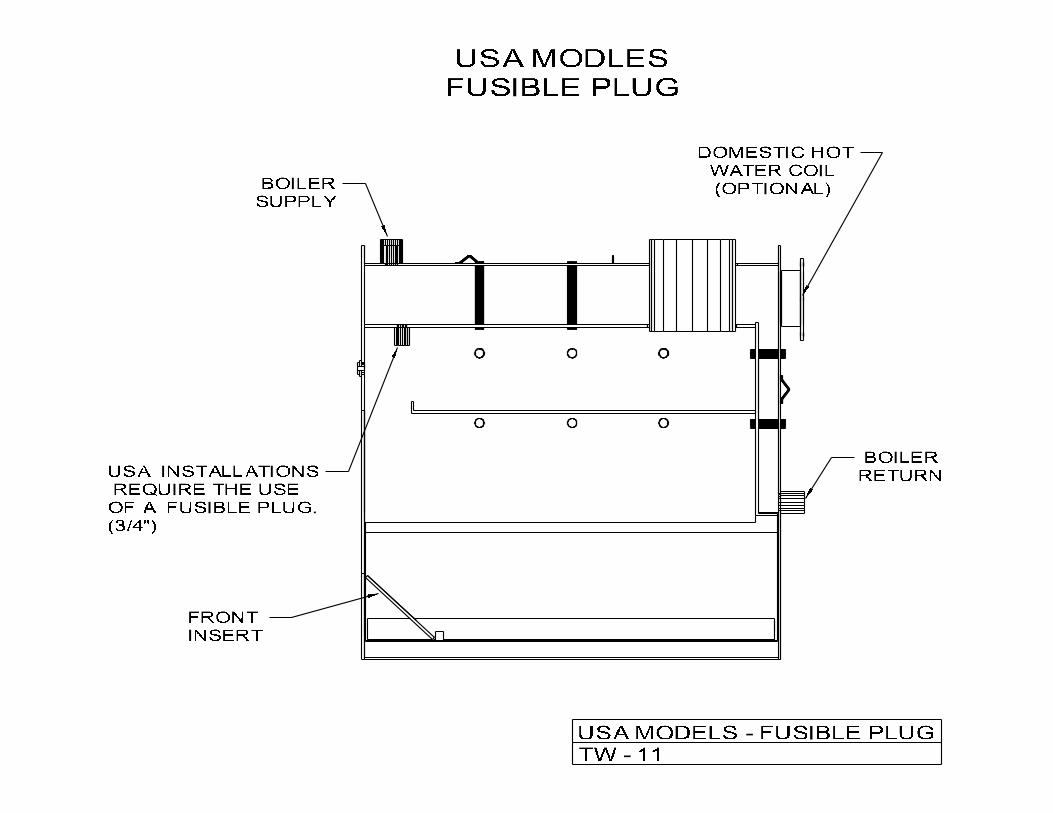
The blow-down extinguishing system is installed to control the fire in case overheating causes excessive pressure in the pressure vessel. The relief valve, included, is threaded into the top of the pressure vessel and copper pipe is installed from its exhaust to the flange above the loading door on the firebox.
In addition to its ability to heat the home, this boiler is provided with a domestic coil position. A copper coil may be purchased with your boiler or added at a later date. It may be utilized as a single water heater or in conjunction with an oil, gas or electric heater.
TW2000 WOOD-FIRED BOILER – INSTRUCTION MANUAL
TW2000 10/6/05
16
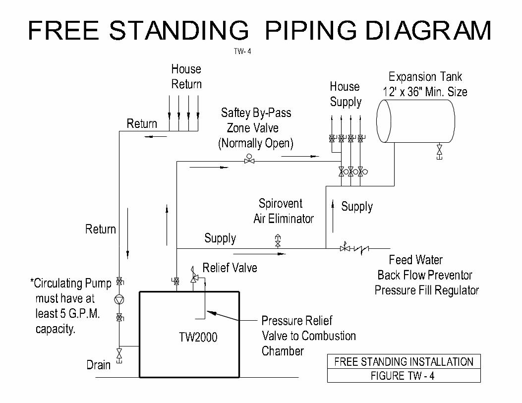
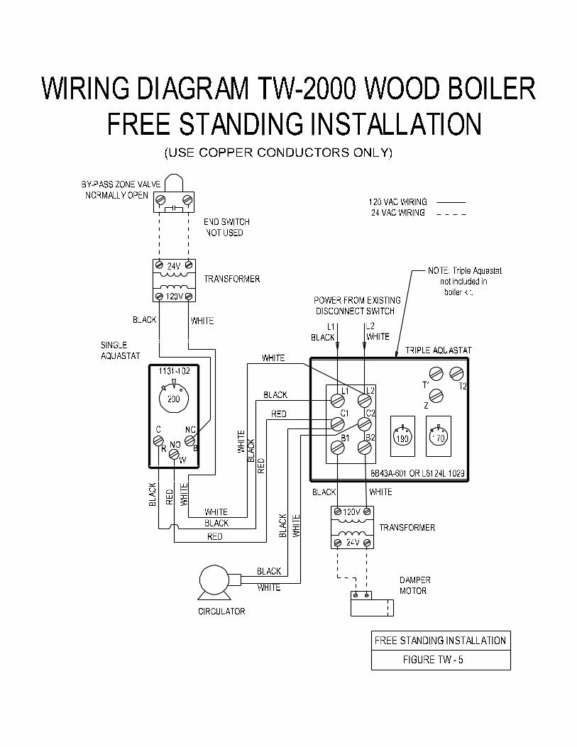
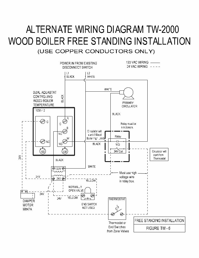
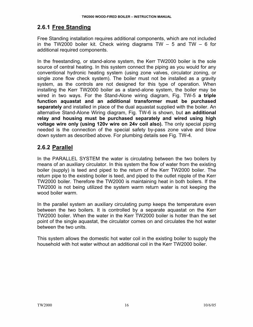
2.6.1 Free Standing Free Standing installation requires additional components, which are not included in the TW2000 boiler kit. Check wiring diagrams TW – 5 and TW – 6 for additional required components.
In the freestanding, or stand-alone system, the Kerr TW2000 boiler is the sole source of central heating. In this system connect the piping as you would for any conventional hydronic heating system (using zone valves, circulator zoning, or single zone flow check system). The boiler must not be installed as a gravity system, as the controls are not designed for this type of operation. When installing the Kerr TW2000 boiler as a stand-alone system, the boiler may be wired in two ways. For the Stand-Alone wiring diagram, Fig. TW-5 a triple function aquastat and an additional transformer must be purchased separately and installed in place of the dual aquastat supplied with the boiler. An alternative Stand-Alone Wiring diagram, Fig. TW-6 is shown, but an additional relay and housing must be purchased separately and wired using high voltage wire only (using 120v wire on 24v coil also). The only special piping needed is the connection of the special safety by-pass zone valve and blow down system as described above. For plumbing details see Fig. TW-4.
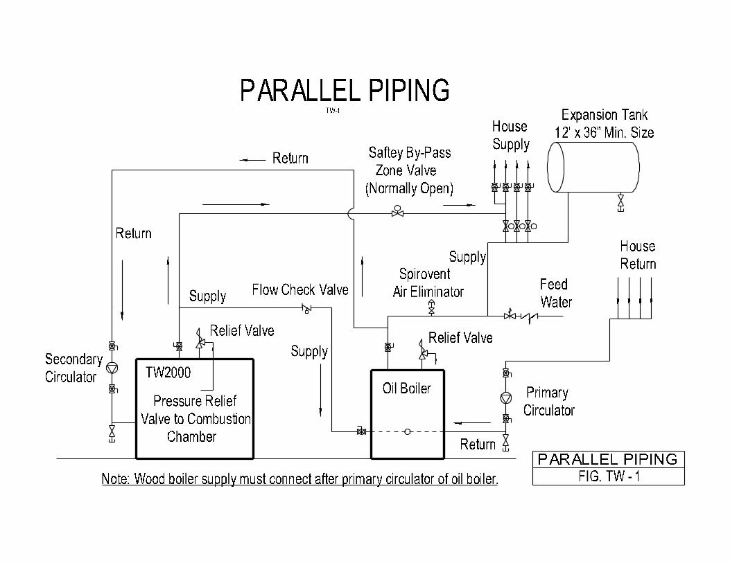
2.6.2 Parallel
In the PARALLEL SYSTEM the water is circulating between the two boilers by means of an auxiliary circulator. In this system the flow of water from the existing boiler (supply) is teed and piped to the return of the Kerr TW2000 boiler. The return pipe to the existing boiler is teed, and piped to the outlet nipple of the Kerr TW2000 boiler. Therefore the TW2000 is maintaining heat in both boilers. If the TW2000 is not being utilized the system warm return water is not keeping the wood boiler warm.
In the parallel system an auxiliary circulating pump keeps the temperature even between the two boilers. It is controlled by a separate aquastat on the Kerr TW2000 boiler. When the water in the Kerr TW2000 boiler is hotter than the set point of the single aquastat, the circulator comes on and circulates the hot water between the two units. This system allows the domestic hot water coil in the existing boiler to supply the household with hot water without an additional coil in the Kerr TW2000 boiler.
TW2000 WOOD-FIRED BOILER – INSTRUCTION MANUAL
TW2000 10/6/05
17
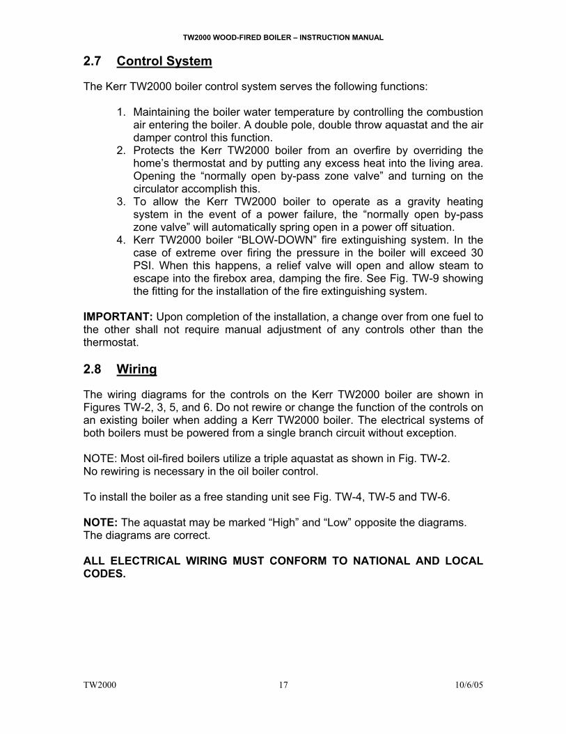
2.7 Control System
The Kerr TW2000 boiler control system serves the following functions: 1. Maintaining the boiler water temperature by controlling the combustion
air entering the boiler. A double pole, double throw aquastat and the air damper control this function.
2. Protects the Kerr TW2000 boiler from an overfire by overriding the home’s thermostat and by putting any excess heat into the living area. Opening the “normally open by-pass zone valve” and turning on the circulator accomplish this.
3. To allow the Kerr TW2000 boiler to operate as a gravity heating system in the event of a power failure, the “normally open by-pass zone valve” will automatically spring open in a power off situation.
4. Kerr TW2000 boiler “BLOW-DOWN” fire extinguishing system. In the case of extreme over firing the pressure in the boiler will exceed 30 PSI. When this happens, a relief valve will open and allow steam to escape into the firebox area, damping the fire. See Fig. TW-9 showing the fitting for the installation of the fire extinguishing system.
IMPORTANT: Upon completion of the installation, a change over from one fuel to the other shall not require manual adjustment of any controls other than the thermostat. 2.8 Wiring
The wiring diagrams for the controls on the Kerr TW2000 boiler are shown in Figures TW-2, 3, 5, and 6. Do not rewire or change the function of the controls on an existing boiler when adding a Kerr TW2000 boiler. The electrical systems of both boilers must be powered from a single branch circuit without exception.
NOTE: Most oil-fired boilers utilize a triple aquastat as shown in Fig. TW-2. No rewiring is necessary in the oil boiler control.
To install the boiler as a free standing unit see Fig. TW-4, TW-5 and TW-6. NOTE: The aquastat may be marked “High” and “Low” opposite the diagrams. The diagrams are correct. ALL ELECTRICAL WIRING MUST CONFORM TO NATIONAL AND LOCAL CODES.
TW2000 WOOD-FIRED BOILER – INSTRUCTION MANUAL
TW2000 10/6/05
18
2.9 DEALER INSTRUCTIONS TO THE HOMEOWNER 1. Keep area around unit clean. 2. Use DRY wood only. Hardwood is preferred. 3. Load carefully. 4. Load level no higher than center of door. 5. Remove ash regularly as directed. 6. Watch for soot build up in smoke pipe. 7. Realize the danger of extreme overheating due to overfiring. 8. Danger of flue fire if poor fuel or poor maintenance produces creosote
buildup. 9. Operation of unit during power failure. (i.e. manual operation of zone
valves and flow check valves). 10. When shutting down for extended periods, clean unit thoroughly. 11. Apply a light coating of motor oil to inside of boiler and other exposed
interior surfaces to protect against rust due to moisture from condensation. 12. Before reloading the boiler with wood, turn up the thermostat 2 to 3
minutes prior to loading to establish the draft. 13. When reloading rake the ashes toward the front and place the new fuel
load toward the rear of the boiler. 14. If, under poor draft conditions, smoke comes out of the door when
reloading, the cast iron baffles may be moved forward on the ledge to allow a ¾” gap behind the baffles. This will allow smoke over the smoldering embers to escape through the gap when the door is opened.
TW2000 WOOD-FIRED BOILER – INSTRUCTION MANUAL
TW2000 10/6/05
19
2.10 Installers Final Checklist
PIPING INSPECTION 1. Boiler plumbed properly? 2. Is a 12” x 36” expansion tank or equivalent installed? 3. Normally open by-pass zone valve installed? 4. Does the normally open zone valve by-pass to the main living area loop? 5. Is the normally open zone valve on the most direct piping loop (fewest
elbows)? BOILER INSPECTION 1. Are clearances maintained? 2. Are all firebricks in place in the boiler? 3. Is the relief valve piped back into the combustion chamber? 4. Is the system full of water and air eliminated? 5. Are zone valves and piping located to prevented drips on controls? WIRING INSPECTION 1. Is main disconnecting switch within view? 2. Wiring cables protected from heat and not touching hot surfaces? 3. Check normally open zone valve (should heat gravity zone when valve
open). 4. Check settings on all aquastats. FLUE AND SMOKE PIPE INSPECTION 1. Flue inner size equivalent to 7” round or larger? 2. Separate entry to flue for both solid-fuel and oil or gas smoke pipes? 3. Smoke pipe 24 gauge or better? 4. Smoke pipe secured by screws? 5. Draft regulator (if used) set at .05” w.c. maximum? 6. Clearances of smoke pipe 18” or better from combustible material?
Metal protection is recommended.
TW2000 WOOD-FIRED BOILER – INSTRUCTION MANUAL
TW2000 10/6/05
20
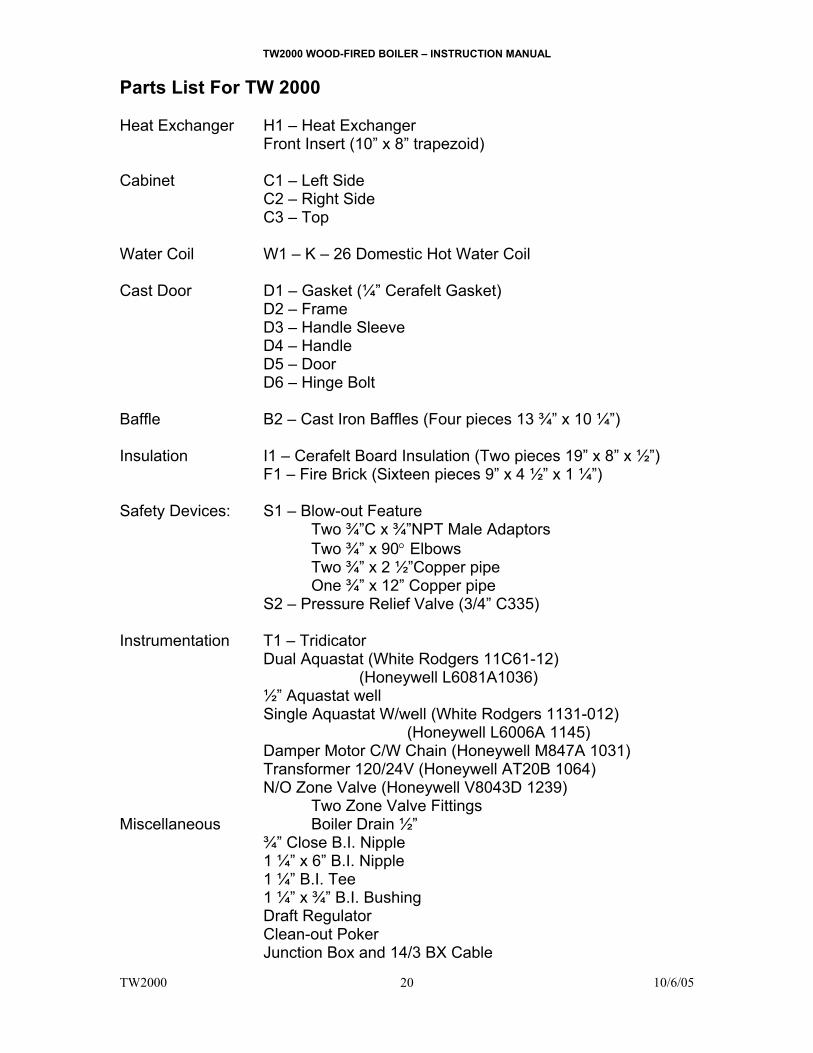
Parts List For TW 2000 Heat Exchanger H1 – Heat Exchanger Front Insert (10” x 8” trapezoid) Cabinet C1 – Left Side C2 – Right Side C3 – Top Water Coil W1 – K – 26 Domestic Hot Water Coil Cast Door D1 – Gasket (¼” Cerafelt Gasket) D2 – Frame D3 – Handle Sleeve D4 – Handle D5 – Door D6 – Hinge Bolt Baffle B2 – Cast Iron Baffles (Four pieces 13 ¾” x 10 ¼”) Insulation I1 – Cerafelt Board Insulation (Two pieces 19” x 8” x ½”) F1 – Fire Brick (Sixteen pieces 9” x 4 ½” x 1 ¼”) Safety Devices: S1 – Blow-out Feature Two ¾”C x ¾”NPT Male Adaptors Two ¾” x 90° Elbows Two ¾” x 2 ½”Copper pipe One ¾” x 12” Copper pipe S2 – Pressure Relief Valve (3/4” C335) Instrumentation T1 – Tridicator Dual Aquastat (White Rodgers 11C61-12)
(Honeywell L6081A1036) ½” Aquastat well Single Aquastat W/well (White Rodgers 1131-012) (Honeywell L6006A 1145) Damper Motor C/W Chain (Honeywell M847A 1031) Transformer 120/24V (Honeywell AT20B 1064) N/O Zone Valve (Honeywell V8043D 1239) Two Zone Valve Fittings Miscellaneous Boiler Drain ½” ¾” Close B.I. Nipple 1 ¼” x 6” B.I. Nipple 1 ¼” B.I. Tee 1 ¼” x ¾” B.I. Bushing Draft Regulator
Clean-out Poker Junction Box and 14/3 BX Cable
TW2000 WOOD-FIRED BOILER – INSTRUCTION MANUAL
TW2000 10/6/05
21
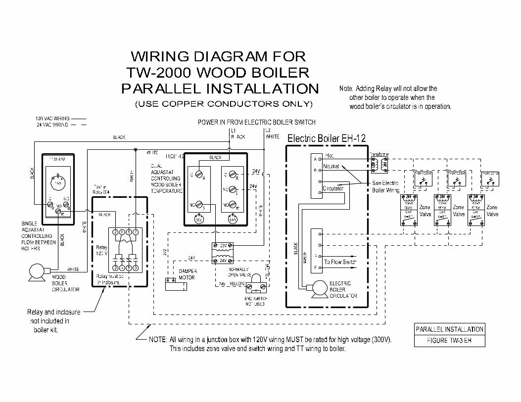
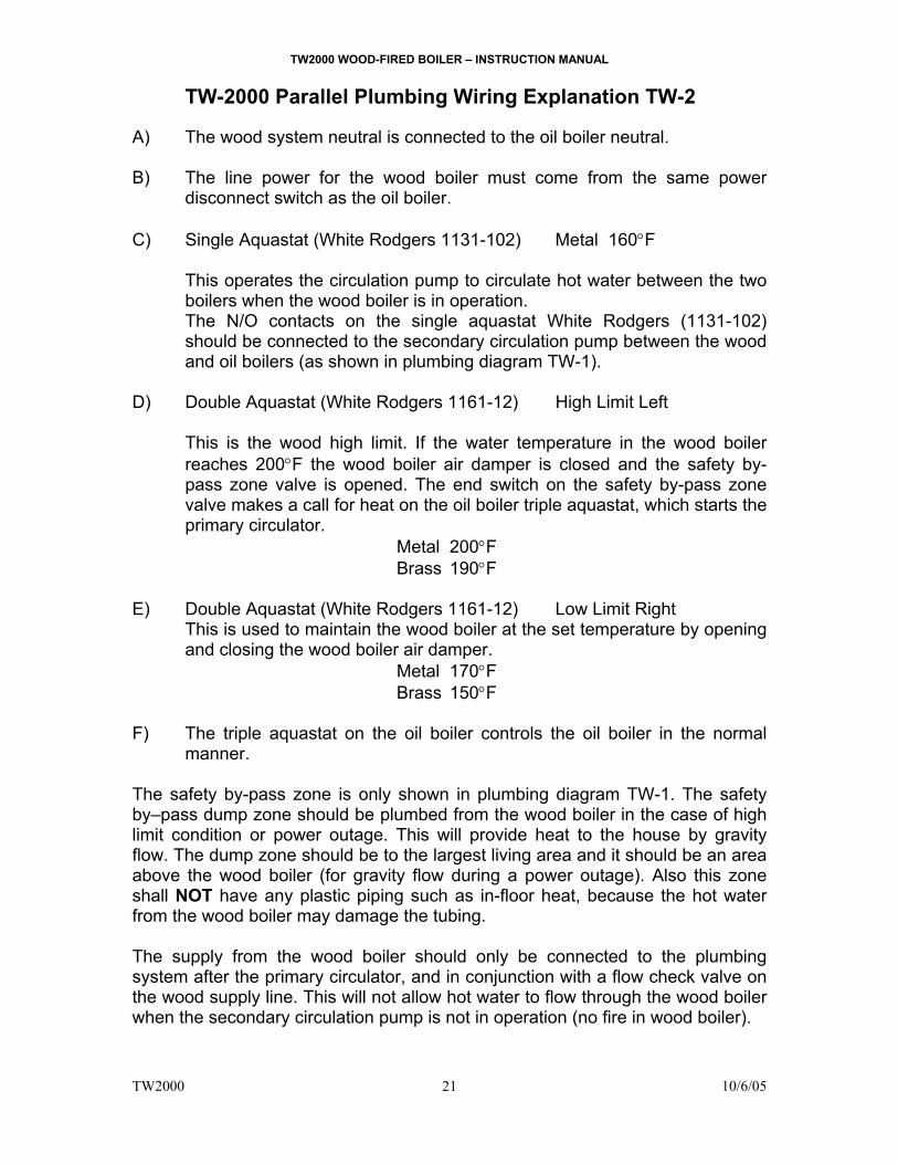
TW-2000 Parallel Plumbing Wiring Explanation TW-2 A) The wood system neutral is connected to the oil boiler neutral. B) The line power for the wood boiler must come from the same power
disconnect switch as the oil boiler.
C) Single Aquastat (White Rodgers 1131-102) Metal 160°F This operates the circulation pump to circulate hot water between the two boilers when the wood boiler is in operation. The N/O contacts on the single aquastat White Rodgers (1131-102) should be connected to the secondary circulation pump between the wood and oil boilers (as shown in plumbing diagram TW-1).
D) Double Aquastat (White Rodgers 1161-12) High Limit Left
This is the wood high limit. If the water temperature in the wood boiler reaches 200°F the wood boiler air damper is closed and the safety by-pass zone valve is opened. The end switch on the safety by-pass zone valve makes a call for heat on the oil boiler triple aquastat, which starts the primary circulator. Metal 200°F
Brass 190°F E) Double Aquastat (White Rodgers 1161-12) Low Limit Right
This is used to maintain the wood boiler at the set temperature by opening and closing the wood boiler air damper.
Metal 170°F Brass 150°F F) The triple aquastat on the oil boiler controls the oil boiler in the normal
manner. The safety by-pass zone is only shown in plumbing diagram TW-1. The safety by–pass dump zone should be plumbed from the wood boiler in the case of high limit condition or power outage. This will provide heat to the house by gravity flow. The dump zone should be to the largest living area and it should be an area above the wood boiler (for gravity flow during a power outage). Also this zone shall NOT have any plastic piping such as in-floor heat, because the hot water from the wood boiler may damage the tubing. The supply from the wood boiler should only be connected to the plumbing system after the primary circulator, and in conjunction with a flow check valve on the wood supply line. This will not allow hot water to flow through the wood boiler when the secondary circulation pump is not in operation (no fire in wood boiler).