Embed Size (px)
Citation preview
1
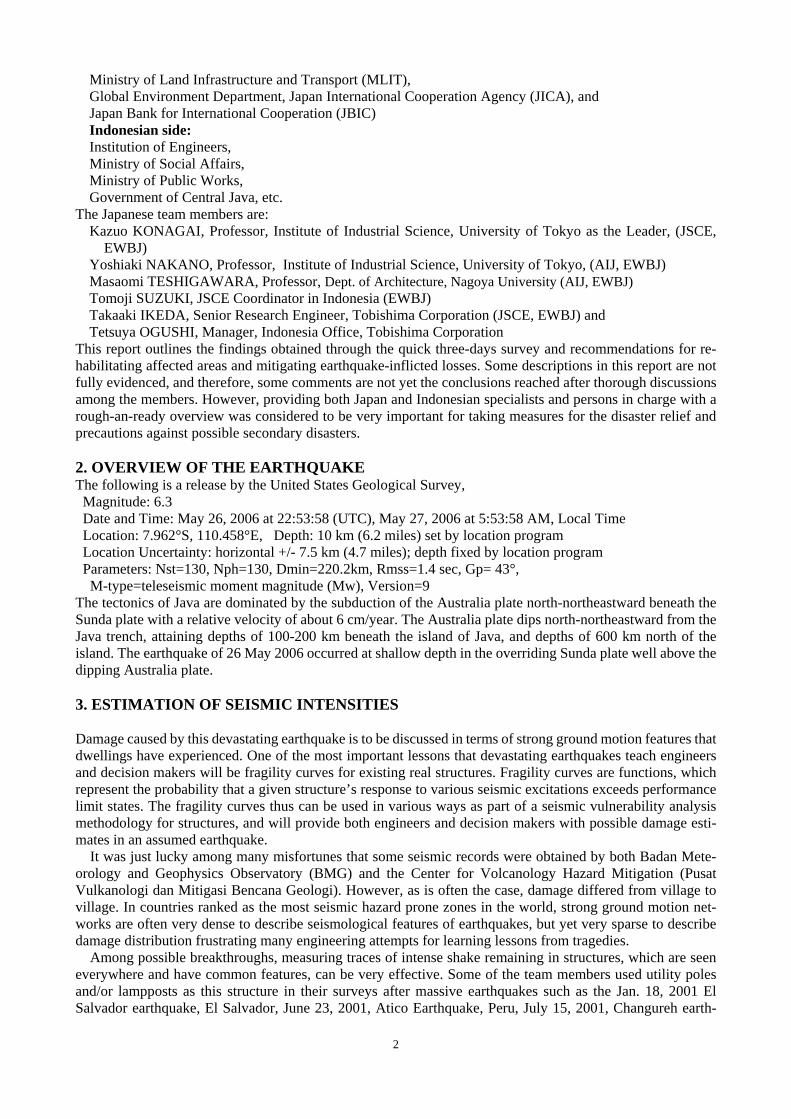
Important Features of the Damage Caused by the May 27, 2006, Mid Java Earthquake, Indonesia
Kazuo KONAGAI1, Yoshiaki NAKANO2, Masaomi TESHIGAWARA3 Tomoji SUZUKI4, Takaaki IKEDA5 and Tetsuya OGUSHI6
1Member of JSCE, Professor, Institute of Industrial Science, University of Tokyo
(Komaba 4-6-1,Meguro-ku, Tokyo 153-8505, Japan) E-mail:[email protected]
2Professor, Institute of Industrial Science, University of Tokyo (Komaba 4-6-1,Meguro-ku, Tokyo 153-8505, Japan)
E-mail:[email protected] 3Professor, Civil Engineering Department, Nagoya University
(Furocho D2-1, Chigusa-ku, Nagoya 464-8601. Japan) E-mail: [email protected]
4JSCE Coordinator in Indonesia E-mail: [email protected]
5Senior Research Engineer, Research Institure of Technology, Tobishima Corporation (Kimagase, Noda, Chiba 270-0222, JAPAN)
E-mail: [email protected] 6formerly Manager, Indonesia Office, Tobishima Corporation
E-mail: [email protected]
A M6.3 earthquake jolted Bantul-Yogyakarta area, Java, Indonesia, on May 27, 2006. This earthquake was not surprisingly large compared to major earthquakes that have ever occurred before in this country, and yet devastations in the affected areas were seriously responsible for the loss of total 5700 lives. This report highlights both building and geotechnical aspects of the damage, and discusses possible causes of typical devastations that the JSCE/AIJ/EWBJ experts observed in their reconnaissance. Key Words :Java, Indonesia, geotechnical problems, detailings of house,
1. INTRODUCTION
A strong earthquake occurred in mid Java Island, Indonesia, at 5:53 local time, May 27, 2006. Though the moderate moment magnitude of 6.3 (United States Geological Survey (USGS) and Earthquake Research In-stitute (ERI), University of Tokyo) calculated for this earthquake was not surprisingly large compared to major earthquakes that have occurred before in this country, Bantul-Yogyakarta area, with Mt. Merapi, spewing hot ash immediately north behind, was seriously ravaged. The death toll keeps rising, and at least 5,700 people were reportedly killed, more than 38,000 injured making this earthquake the worst natural disaster in Indonesia since the tsunami of Dec. 26, 2004.
Japan Society of Civil Engineers (JSCE), with the approval of the Architectural Institute of Japan (AIJ), is establishing a non-profit organization (NPO), “Engineers without Borders, Japan (EWBJ)” to contribute to retrofitting and reconstructing areas affected by natural disasters. Both JSCE and AIJ decided that they would dispatch a quick advance team to Indonesia (June 10- 17, 2006). The preliminary strategy of JSCE/AIJ ad-vance team was to make a first reconnaissance laying stress on the damage to dwellings, civil infrastructures etc, and then to discuss with experts from both Japan and Indonesian organizations about tactics for better rehabilitation. The team had been sharing necessary information among the following Japanese and Indonesian organizations:
Japanese side: Asian and Oceanian Affairs Bureau, Ministry of Foreign Affairs (MOFA),
2
Ministry of Land Infrastructure and Transport (MLIT), Global Environment Department, Japan International Cooperation Agency (JICA), and Japan Bank for International Cooperation (JBIC) Indonesian side: Institution of Engineers, Ministry of Social Affairs, Ministry of Public Works, Government of Central Java, etc.
The Japanese team members are: Kazuo KONAGAI, Professor, Institute of Industrial Science, University of Tokyo as the Leader, (JSCE,
EWBJ) Yoshiaki NAKANO, Professor, Institute of Industrial Science, University of Tokyo, (AIJ, EWBJ) Masaomi TESHIGAWARA, Professor, Dept. of Architecture, Nagoya University (AIJ, EWBJ) Tomoji SUZUKI, JSCE Coordinator in Indonesia (EWBJ) Takaaki IKEDA, Senior Research Engineer, Tobishima Corporation (JSCE, EWBJ) and Tetsuya OGUSHI, Manager, Indonesia Office, Tobishima Corporation
This report outlines the findings obtained through the quick three-days survey and recommendations for re-habilitating affected areas and mitigating earthquake-inflicted losses. Some descriptions in this report are not fully evidenced, and therefore, some comments are not yet the conclusions reached after thorough discussions among the members. However, providing both Japan and Indonesian specialists and persons in charge with a rough-an-ready overview was considered to be very important for taking measures for the disaster relief and precautions against possible secondary disasters. 2. OVERVIEW OF THE EARTHQUAKE The following is a release by the United States Geological Survey, Magnitude: 6.3 Date and Time: May 26, 2006 at 22:53:58 (UTC), May 27, 2006 at 5:53:58 AM, Local Time Location: 7.962°S, 110.458°E, Depth: 10 km (6.2 miles) set by location program Location Uncertainty: horizontal +/- 7.5 km (4.7 miles); depth fixed by location program Parameters: Nst=130, Nph=130, Dmin=220.2km, Rmss=1.4 sec, Gp= 43°,
M-type=teleseismic moment magnitude (Mw), Version=9 The tectonics of Java are dominated by the subduction of the Australia plate north-northeastward beneath the Sunda plate with a relative velocity of about 6 cm/year. The Australia plate dips north-northeastward from the Java trench, attaining depths of 100-200 km beneath the island of Java, and depths of 600 km north of the island. The earthquake of 26 May 2006 occurred at shallow depth in the overriding Sunda plate well above the dipping Australia plate. 3. ESTIMATION OF SEISMIC INTENSITIES Damage caused by this devastating earthquake is to be discussed in terms of strong ground motion features that dwellings have experienced. One of the most important lessons that devastating earthquakes teach engineers and decision makers will be fragility curves for existing real structures. Fragility curves are functions, which represent the probability that a given structure’s response to various seismic excitations exceeds performance limit states. The fragility curves thus can be used in various ways as part of a seismic vulnerability analysis methodology for structures, and will provide both engineers and decision makers with possible damage esti-mates in an assumed earthquake.
It was just lucky among many misfortunes that some seismic records were obtained by both Badan Mete-orology and Geophysics Observatory (BMG) and the Center for Volcanology Hazard Mitigation (Pusat Vulkanologi dan Mitigasi Bencana Geologi). However, as is often the case, damage differed from village to village. In countries ranked as the most seismic hazard prone zones in the world, strong ground motion net-works are often very dense to describe seismological features of earthquakes, but yet very sparse to describe damage distribution frustrating many engineering attempts for learning lessons from tragedies.
Among possible breakthroughs, measuring traces of intense shake remaining in structures, which are seen everywhere and have common features, can be very effective. Some of the team members used utility poles and/or lampposts as this structure in their surveys after massive earthquakes such as the Jan. 18, 2001 El Salvador earthquake, El Salvador, June 23, 2001, Atico Earthquake, Peru, July 15, 2001, Changureh earth-
3
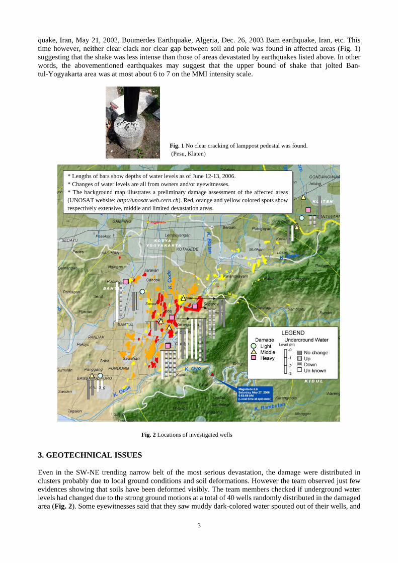
quake, Iran, May 21, 2002, Boumerdes Earthquake, Algeria, Dec. 26, 2003 Bam earthquake, Iran, etc. This time however, neither clear clack nor clear gap between soil and pole was found in affected areas (Fig. 1) suggesting that the shake was less intense than those of areas devastated by earthquakes listed above. In other words, the abovementioned earthquakes may suggest that the upper bound of shake that jolted Ban-tul-Yogyakarta area was at most about 6 to 7 on the MMI intensity scale.
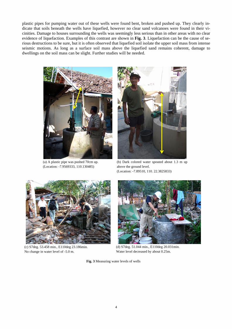
3. GEOTECHNICAL ISSUES Even in the SW-NE trending narrow belt of the most serious devastation, the damage were distributed in clusters probably due to local ground conditions and soil deformations. However the team observed just few evidences showing that soils have been deformed visibly. The team members checked if underground water levels had changed due to the strong ground motions at a total of 40 wells randomly distributed in the damaged area (Fig. 2). Some eyewitnesses said that they saw muddy dark-colored water spouted out of their wells, and
Fig. 1 No clear cracking of lamppost pedestal was found. (Pesu, Klaten)
* Lengths of bars show depths of water levels as of June 12-13, 2006. * Changes of water levels are all from owners and/or eyewitnesses. * The background map illustrates a preliminary damage assessment of the affected areas (UNOSAT website: http://unosat.web.cern.ch). Red, orange and yellow colored spots show respectively extensive, middle and limited devastation areas.
Fig. 2 Locations of investigated wells
4
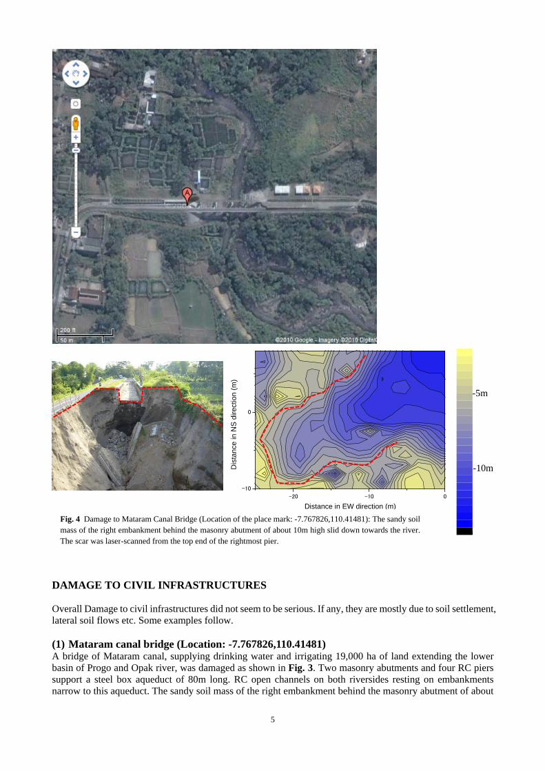
plastic pipes for pumping water out of these wells were found bent, broken and pushed up. They clearly in-dicate that soils beneath the wells have liquefied, however no clear sand volcanoes were found in their vi-cinities. Damage to houses surrounding the wells was seemingly less serious than in other areas with no clear evidence of liquefaction. Examples of this contrast are shown in Fig. 3. Liquefaction can be the cause of se-rious destructions to be sure, but it is often observed that liquefied soil isolate the upper soil mass from intense seismic motions. As long as a surface soil mass above the liquefied sand remains coherent, damage to dwellings on the soil mass can be slight. Further studies will be needed.
(a) A plastic pipe was pushed 70cm up. (Location: -7.9569333, 110.130485)
(b) Dark colored water spouted about 1.3 m up above the ground level. (Location: -7.89510, 110. 22.3825833)
(c) S7deg. 53.458 min., E110deg 23.186min. No change in water level of -5.0 m.
(d) S7deg. 51.044 min., E110deg 20.031min. Water level decreased by about 0.25m.
Fig. 3 Measuring water levels of wells
5
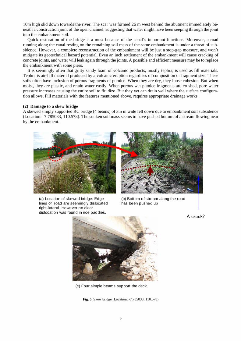
DAMAGE TO CIVIL INFRASTRUCTURES Overall Damage to civil infrastructures did not seem to be serious. If any, they are mostly due to soil settlement, lateral soil flows etc. Some examples follow. (1) Mataram canal bridge (Location: -7.767826,110.41481) A bridge of Mataram canal, supplying drinking water and irrigating 19,000 ha of land extending the lower basin of Progo and Opak river, was damaged as shown in Fig. 3. Two masonry abutments and four RC piers support a steel box aqueduct of 80m long. RC open channels on both riversides resting on embankments narrow to this aqueduct. The sandy soil mass of the right embankment behind the masonry abutment of about
-20 -10 0
-10
0
Distance in EW direction (m)
Dis
tanc
e in
NS
dire
ctio
n (m
)
-14.00
-13.50
-13.00
-12.50
-12.00
-11.50
-11.00
-10.50
-10.00
-9.500
-9.000
-8.500
-8.000
-7.500
-7.000
-6.500
-6.000
-5.500
-5.000
-4.500
-4.000
-3.500
-3.000
-2.500
-2.274
-10m
-5m
Fig. 4 Damage to Mataram Canal Bridge (Location of the place mark: -7.767826,110.41481): The sandy soil mass of the right embankment behind the masonry abutment of about 10m high slid down towards the river. The scar was laser-scanned from the top end of the rightmost pier.
6
10m high slid down towards the river. The scar was formed 26 m west behind the abutment immediately be-neath a construction joint of the open channel, suggesting that water might have been seeping through the joint into the embankment soil.
Quick restoration of the bridge is a must because of the canal’s important functions. Moreover, a road running along the canal resting on the remaining soil mass of the same embankment is under a threat of sub-sidence. However, a complete reconstruction of the embankment will be just a stop-gap measure, and won’t mitigate its geotechnical hazard potential. Even an inch settlement of the embankment will cause cracking of concrete joints, and water will leak again through the joints. A possible and efficient measure may be to replace the embankment with some piers.
It is seemingly often that gritty sandy loam of volcanic products, mostly tephra, is used as fill materials. Tephra is air-fall material produced by a volcanic eruption regardless of composition or fragment size. These soils often have inclusion of porous fragments of pumice. When they are dry, they loose cohesion. But when moist, they are plastic, and retain water easily. When porous wet pumice fragments are crushed, pore water pressure increases causing the entire soil to fluidize. But they yet can drain well where the surface configura-tion allows. Fill materials with the features mentioned above, requires appropriate drainage works. (2) Damage to a skew bridge A skewed simply supported RC bridge (4 beams) of 3.5 m wide fell down due to embankment soil subsidence (Location: -7.785033, 110.578). The sunken soil mass seems to have pushed bottom of a stream flowing near by the embankment.
(a) Location of skewed bridge: Edge lines of road are seemingly dislocated right-lateral. However no clear dislocation was found in rice paddies.
(b) Bottom of stream along the road has been pushed up
(c) Four simple beams support the deck.
A crack?
Fig. 5 Skew bridge (Location: -7.785033, 110.578)
7
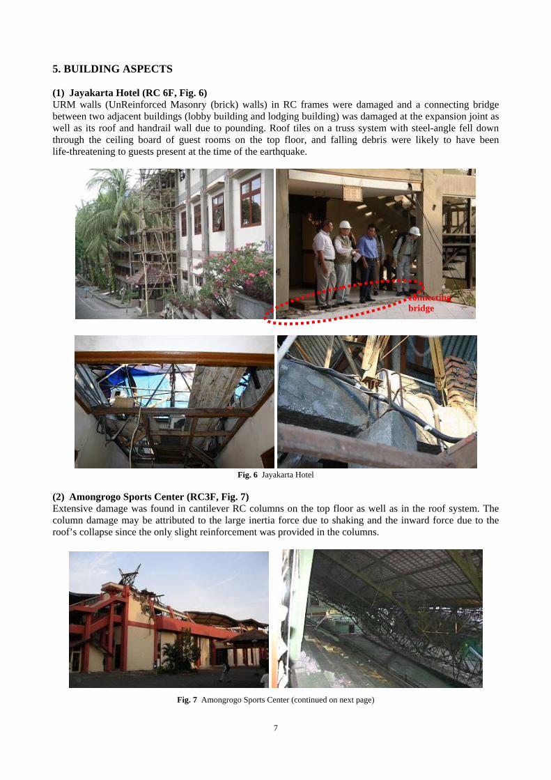
5. BUILDING ASPECTS (1) Jayakarta Hotel (RC 6F, Fig. 6) URM walls (UnReinforced Masonry (brick) walls) in RC frames were damaged and a connecting bridge between two adjacent buildings (lobby building and lodging building) was damaged at the expansion joint as well as its roof and handrail wall due to pounding. Roof tiles on a truss system with steel-angle fell down through the ceiling board of guest rooms on the top floor, and falling debris were likely to have been life-threatening to guests present at the time of the earthquake.
Fig. 6 Jayakarta Hotel
(2) Amongrogo Sports Center (RC3F, Fig. 7) Extensive damage was found in cantilever RC columns on the top floor as well as in the roof system. The column damage may be attributed to the large inertia force due to shaking and the inward force due to the roof’s collapse since the only slight reinforcement was provided in the columns.
Fig. 7 Amongrogo Sports Center (continued on next page)
connecting bridge
8
Fig. 7 Amongrogo Sports Center
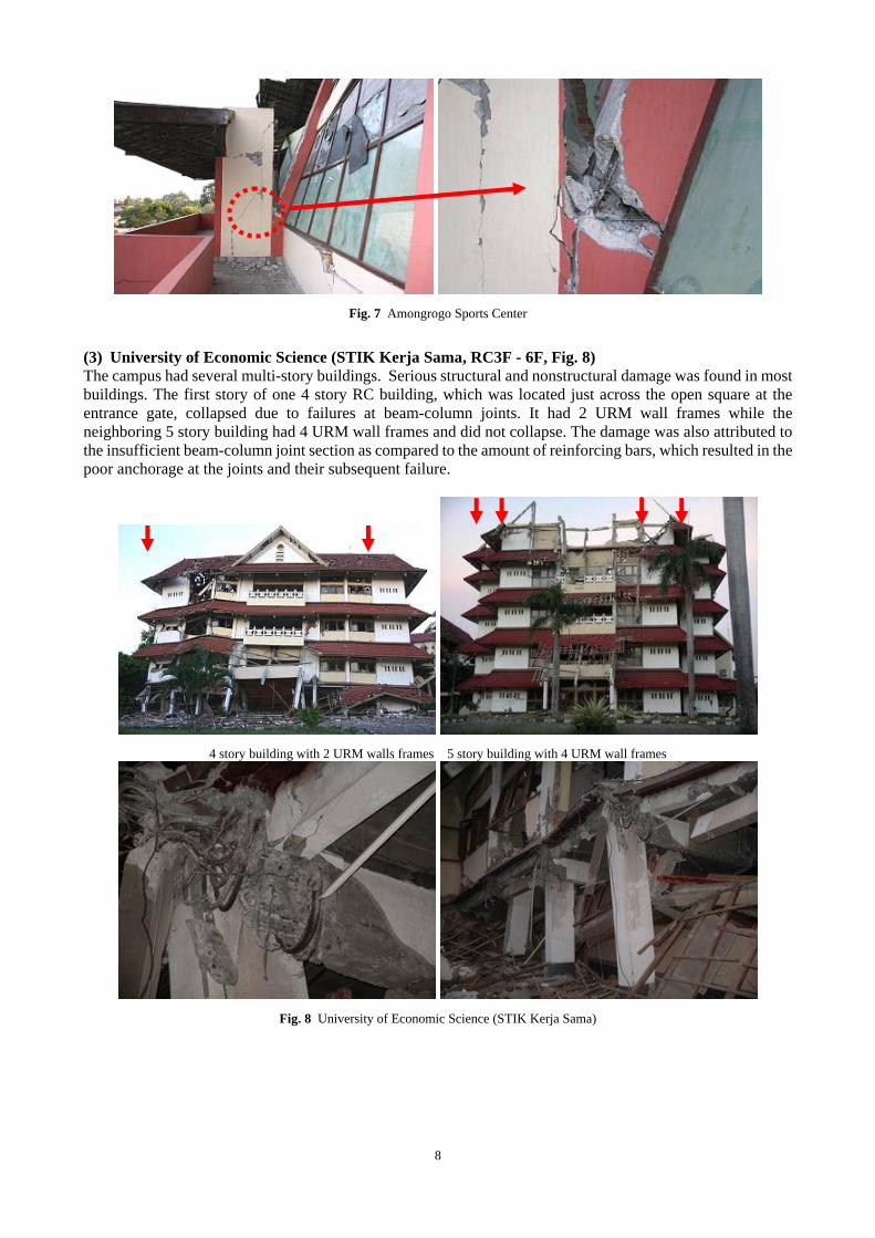
(3) University of Economic Science (STIK Kerja Sama, RC3F - 6F, Fig. 8) The campus had several multi-story buildings. Serious structural and nonstructural damage was found in most buildings. The first story of one 4 story RC building, which was located just across the open square at the entrance gate, collapsed due to failures at beam-column joints. It had 2 URM wall frames while the neighboring 5 story building had 4 URM wall frames and did not collapse. The damage was also attributed to the insufficient beam-column joint section as compared to the amount of reinforcing bars, which resulted in the poor anchorage at the joints and their subsequent failure.
4 story building with 2 URM walls frames 5 story building with 4 URM wall frames
Fig. 8 University of Economic Science (STIK Kerja Sama)
9
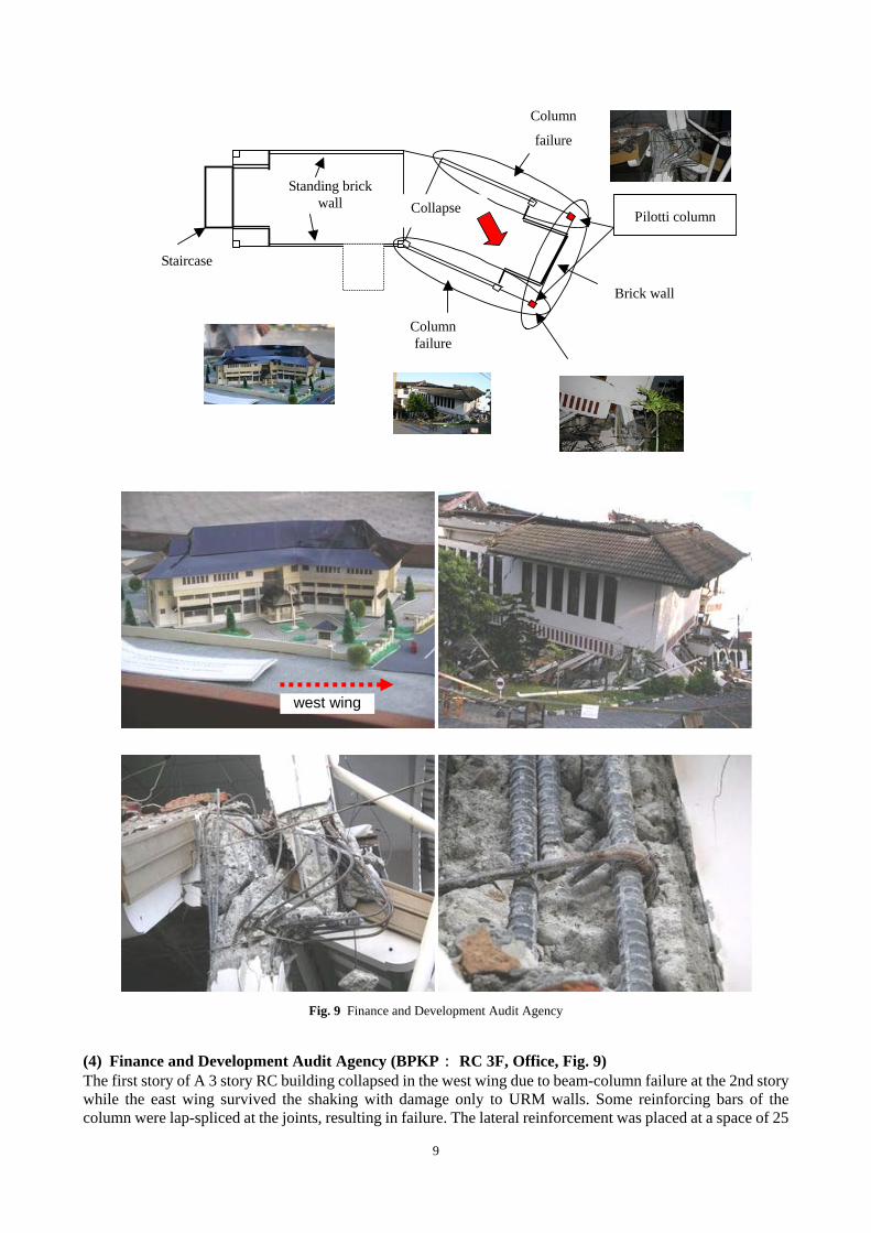
Staircase
Standing brick wall
Pilotti column Collapse
Brick wall
Column failure
Column
failure
Fig. 9 Finance and Development Audit Agency
(4) Finance and Development Audit Agency (BPKP: RC 3F, Office, Fig. 9) The first story of A 3 story RC building collapsed in the west wing due to beam-column failure at the 2nd story while the east wing survived the shaking with damage only to URM walls. Some reinforcing bars of the column were lap-spliced at the joints, resulting in failure. The lateral reinforcement was placed at a space of 25
west wing
10
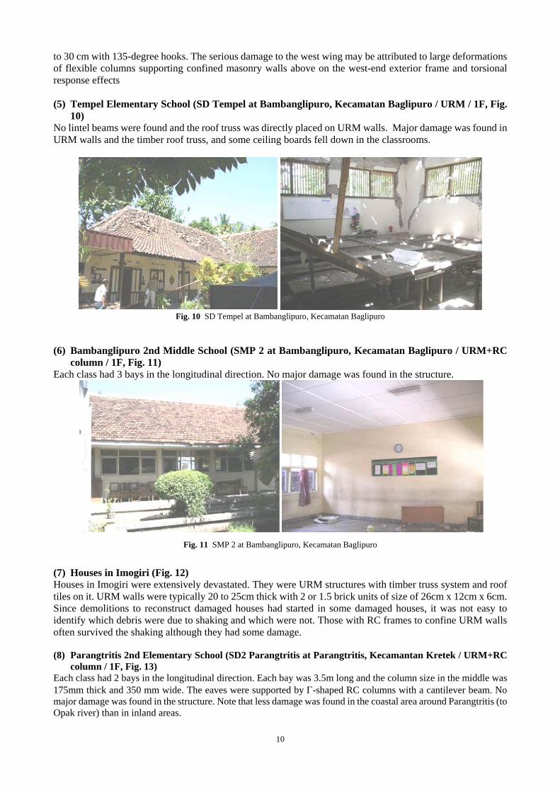
to 30 cm with 135-degree hooks. The serious damage to the west wing may be attributed to large deformations of flexible columns supporting confined masonry walls above on the west-end exterior frame and torsional response effects (5) Tempel Elementary School (SD Tempel at Bambanglipuro, Kecamatan Baglipuro / URM / 1F, Fig.
10) No lintel beams were found and the roof truss was directly placed on URM walls. Major damage was found in URM walls and the timber roof truss, and some ceiling boards fell down in the classrooms.
Fig. 10 SD Tempel at Bambanglipuro, Kecamatan Baglipuro
(6) Bambanglipuro 2nd Middle School (SMP 2 at Bambanglipuro, Kecamatan Baglipuro / URM+RC
column / 1F, Fig. 11) Each class had 3 bays in the longitudinal direction. No major damage was found in the structure.
Fig. 11 SMP 2 at Bambanglipuro, Kecamatan Baglipuro
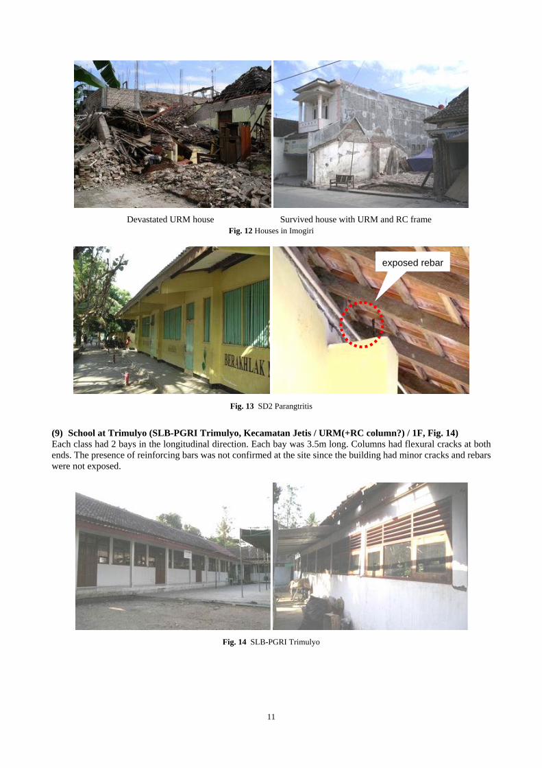
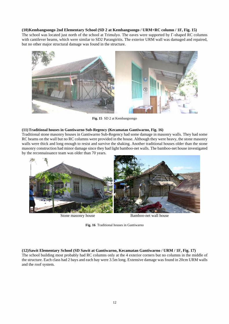
(7) Houses in Imogiri (Fig. 12) Houses in Imogiri were extensively devastated. They were URM structures with timber truss system and roof tiles on it. URM walls were typically 20 to 25cm thick with 2 or 1.5 brick units of size of 26cm x 12cm x 6cm. Since demolitions to reconstruct damaged houses had started in some damaged houses, it was not easy to identify which debris were due to shaking and which were not. Those with RC frames to confine URM walls often survived the shaking although they had some damage. (8) Parangtritis 2nd Elementary School (SD2 Parangtritis at Parangtritis, Kecamantan Kretek / URM+RC
column / 1F, Fig. 13) Each class had 2 bays in the longitudinal direction. Each bay was 3.5m long and the column size in the middle was 175mm thick and 350 mm wide. The eaves were supported by Γ-shaped RC columns with a cantilever beam. No major damage was found in the structure. Note that less damage was found in the coastal area around Parangtritis (to Opak river) than in inland areas.
11
Devastated URM house Survived house with URM and RC frame
Fig. 12 Houses in Imogiri
Fig. 13 SD2 Parangtritis
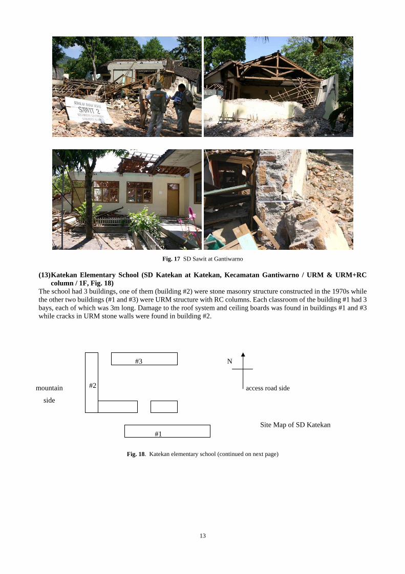
(9) School at Trimulyo (SLB-PGRI Trimulyo, Kecamatan Jetis / URM(+RC column?) / 1F, Fig. 14) Each class had 2 bays in the longitudinal direction. Each bay was 3.5m long. Columns had flexural cracks at both ends. The presence of reinforcing bars was not confirmed at the site since the building had minor cracks and rebars were not exposed.
Fig. 14 SLB-PGRI Trimulyo
exposed rebar
12
(10) Kembangsongo 2nd Elementary School (SD 2 at Kembangsongo / URM+RC column / 1F, Fig. 15) The school was located just north of the school at Trimulyo. The eaves were supported by Γ-shaped RC columns with cantilever beams, which were similar to SD2 Parangtritis. The exterior URM wall was damaged and repaired, but no other major structural damage was found in the structure.
Fig. 15 SD 2 at Kembangsongo
(11) Traditional houses in Gantiwarno Sub-Regency (Kecamatan Gantiwarno, Fig. 16) Traditional stone masonry houses in Gantiwarno Sub-Regency had some damage in masonry walls. They had some RC beams on the wall but no RC columns were provided in the house. Although they were heavy, the stone masonry walls were thick and long enough to resist and survive the shaking. Another traditional houses older than the stone masonry construction had minor damage since they had light bamboo-net walls. The bamboo-net house investigated by the reconnaissance team was older than 70 years.
Stone masonry house Bamboo-net wall house
Fig. 16 Traditional houses in Gantiwarno
(12) Sawit Elementary School (SD Sawit at Gantiwarno, Kecamatan Gantiwarno / URM / 1F, Fig. 17) The school building most probably had RC columns only at the 4 exterior corners but no columns in the middle of the structure. Each class had 2 bays and each bay were 3.5m long. Extensive damage was found in 20cm URM walls and the roof system.
13
Fig. 17 SD Sawit at Gantiwarno
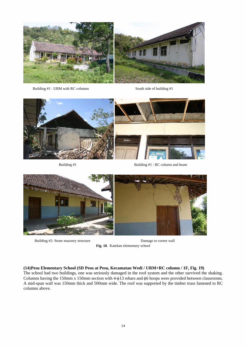
(13) Katekan Elementary School (SD Katekan at Katekan, Kecamatan Gantiwarno / URM & URM+RC
column / 1F, Fig. 18) The school had 3 buildings, one of them (building #2) were stone masonry structure constructed in the 1970s while the other two buildings (#1 and #3) were URM structure with RC columns. Each classroom of the building #1 had 3 bays, each of which was 3m long. Damage to the roof system and ceiling boards was found in buildings #1 and #3 while cracks in URM stone walls were found in building #2.
Fig. 18. Katekan elementary school (continued on next page)
N
#1
#2
#3
mountain
side
access road side
Site Map of SD Katekan
14
Building #1 : URM with RC columns South side of building #1
Building #1 Building #1 : RC column and beam
Building #2: Stone masonry structure Damage to corner wall
Fig. 18. Katekan elementary school
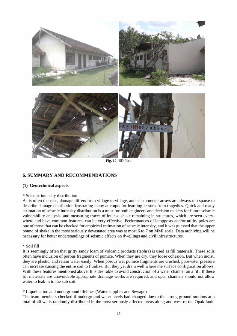
(14) Pesu Elementary School (SD Pesu at Pesu, Kecamatan Wedi / URM+RC column / 1F, Fig. 19) The school had two buildings, one was seriously damaged in the roof system and the other survived the shaking. Columns having the 150mm x 150mm section with 4-φ13 rebars and φ6 hoops were provided between classrooms. A mid-span wall was 150mm thick and 500mm wide. The roof was supported by the timber truss fastened to RC columns above.
15
Fig. 19 SD Pesu
6. SUMMARY AND RECOMMENDATIONS (1) Geotechnical aspects * Seismic intensity distribution As is often the case, damage differs from village to village, and seismometer arrays are always too sparse to describe damage distribution frustrating many attempts for learning lessons from tragedies. Quick and ready estimation of seismic intensity distribution is a must for both engineers and decision makers for future seismic vulnerability analysis, and measuring traces of intense shake remaining in structures, which are seen every-where and have common features, can be very effective. Performances of lampposts and/or utility poles are one of those that can be checked for empirical estimation of seismic intensity, and it was guessed that the upper bound of shake in the most seriously devastated area was at most 6 to 7 on MMI scale. Data archiving will be necessary for better understandings of seismic effects on dwellings and civil infrastructures. * Soil fill It is seemingly often that gritty sandy loam of volcanic products (tephra) is used as fill materials. These soils often have inclusion of porous fragments of pumice. When they are dry, they loose cohesion. But when moist, they are plastic, and retain water easily. When porous wet pumice fragments are crushed, porewater pressure can increase causing the entire soil to fluidize. But they yet drain well where the surface configuration allows. With these features mentioned above, It is desirable to avoid construction of a water channel on a fill. If these fill materials are unavoidable appropriate drainage works are required, and open channels should not allow water to leak in to the sub soil. * Liquefaction and underground lifelines (Water supplies and Sewage) The team members checked if underground water levels had changed due to the strong ground motions at a total of 40 wells randomly distributed in the most seriously affected areas along and west of the Opak fault.
16
Some eyewitnesses said that they saw muddy water spouted out of their wells, and plastic pipes for pumping water out of these wells were found bent, broken and pushed up. They clearly say that soils beneath the wells have liquefied, while no clear sand volcanoes were found in their vicinities. This is firstly because the ground was covered thick with cohesive clay loam, and secondly the shake was not intense for the built-up pore-water pressure to force its way up through the surface clay-loamy soils. However the liquefaction was certainly responsible for destroying and/or clogging of wells. For water supply systems and sewage systems, these features of soils are to be studied. * Hazard mapping Local soil conditions and surface soil profiles can change seismic motions remarkably. Borehole data are to be archived for hazard mappings for important areas. * Volcanic hazards For now, there is no convincing direct links between volcanic activity and the earthquake of May 27. However for possible disaster mitigation, information of some mechanical features of pyroclastic flows and lahars such as their velocities, locations and total volumes of sources (lava domes etc), is to be shared by both volca-nologists and engineering experts. (2) Building aspects * Damage to URM walls Devastating damage was found in URM houses in Bantul Regency, Yogyakarta City, and Klaten Regency, killing residents due to heavy debris of brick walls. URM houses with RC beams and columns confining URM walls, however, had relatively less damage, even when they had some damage. Providing RC frames to confine masonry walls is strongly recommended to reduce structural damage to URM houses. Educational programs would provide opportunities to train practitioners and to disseminate the important role of confining frames. * Damage to Roof system Even when a building had minor structural damage, some schools had significant damage to their roof system. Since the earthquake occurred early in the morning, the loss of human lives was minimized. Falling debris such as bricks, ceiling boards, roof tiles etc. are significantly life-threatening especially to school children. The structure underneath the roof should be rigid and strong enough to properly support the roof system. As pointed out in (1), providing RC frames is strongly recommended to provide sufficient in-plane and out-of-plane stiffness and strength of buildings. * Beam-column joints of RC buildings Concrete spalling at beam-column joints is observed in some buildings, exposing the buckled longitudinal reinforcement. Rigid beam-column joints properly confined with lateral reinforcement are most essential for RC structures to perform successfully during earthquakes. Congestion of rebars was found in some buildings. It is also essential to provide enough concrete volume at the beam-column joints for sufficient embedment length and anchorage of reinforcing bars. The geometry size of beams and columns therefore should be large enough to transfer actions and to form yield hinges in mem-bers before the joint failure. * Pounding Closely neighboring buildings with narrow gaps at expansion joints sustained pounding damage. Expansion joints should be therefore designed and constructed properly considering deformations expected during shaking. * Comparison of seismic capacity of buildings and their observed damage School buildings in the affected areas could be categorized in several structural types. Since they were single story and had simple structural plans, their seismic capacity could be calculated based on a simplified struc-tural model. Comparing the capacity of an identical structural plan with their observed damage in different locations may serve as a tool to estimate the earthquake intensity although strong motion records were not fully available in the affected area. Furthermore, the obtained results would be of great help to discuss the required capacity of buildings against future earthquakes.
17
* Relationship between city development and damage distribution Damage observed in the Yogyakarta city seemed localized, although not fully and statistically investigated during this survey, and this may be strongly affected by the development process of the affected areas (old city area, expanded new city area, volcano ash deposit area, former river stream etc.). The background history of the area may help understand the damage distribution and propose a future city planning as well as recon-struction strategies. SUPPLEMENT: SEQUEL TO THIS REPORT The earthquake was followed by an undersea earthquake again, which took place off the southern coast of Java island on July 17, 2006. The shake felt on the Java Island was not intense enough to cause any immediate casualties, but tsunami smashed into a 180 km stretch of Java’s coast line about one hour, killing at least 550 people and leaving at least 229 missing. The Japan Society of Civil Engineers (JSCE), the Architectural Institution of Japan (AIJ) and the “Engineers without Borders, Japan, again dispatched a team of experts including the first and the third authors of this report.
Taking this opportunity, they visited Mataram canal bridge (See page 5 of this report). Our recommendation given to relevant bureaus was as follows: “Quick restoration of the bridge is a must because of the canal’s important functions. Moreover, a road running along the canal resting on the remaining soil mass of the same embankment is under a threat of subsidence. However, a complete reconstruction of the embankment will be just a stop-gap measure, and won’t mitigate its geotechnical hazard potential. Even an inch settlement of the embankment will cause cracking of concrete joints, and water will leak again through the joints. A possible and efficient measure may be to replace the embankment with some piers.”
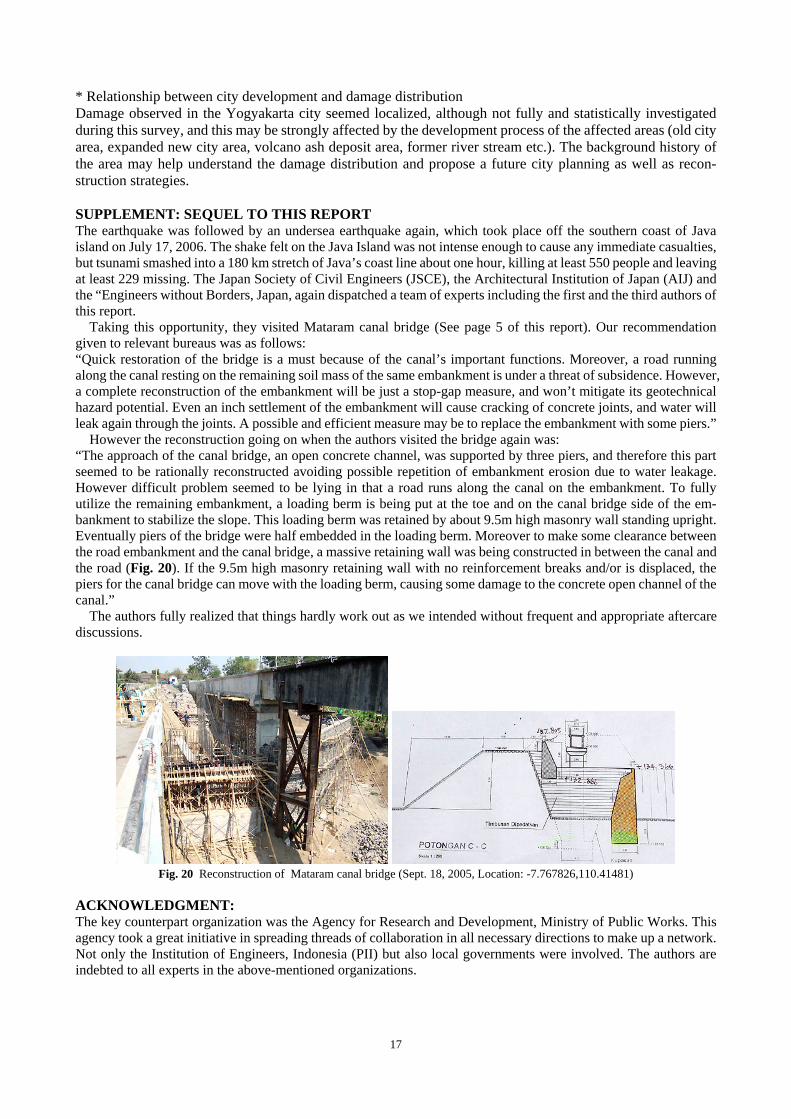
However the reconstruction going on when the authors visited the bridge again was: “The approach of the canal bridge, an open concrete channel, was supported by three piers, and therefore this part seemed to be rationally reconstructed avoiding possible repetition of embankment erosion due to water leakage. However difficult problem seemed to be lying in that a road runs along the canal on the embankment. To fully utilize the remaining embankment, a loading berm is being put at the toe and on the canal bridge side of the em-bankment to stabilize the slope. This loading berm was retained by about 9.5m high masonry wall standing upright. Eventually piers of the bridge were half embedded in the loading berm. Moreover to make some clearance between the road embankment and the canal bridge, a massive retaining wall was being constructed in between the canal and the road (Fig. 20). If the 9.5m high masonry retaining wall with no reinforcement breaks and/or is displaced, the piers for the canal bridge can move with the loading berm, causing some damage to the concrete open channel of the canal.”
The authors fully realized that things hardly work out as we intended without frequent and appropriate aftercare discussions.
Fig. 20 Reconstruction of Mataram canal bridge (Sept. 18, 2005, Location: -7.767826,110.41481)
ACKNOWLEDGMENT: The key counterpart organization was the Agency for Research and Development, Ministry of Public Works. This agency took a great initiative in spreading threads of collaboration in all necessary directions to make up a network. Not only the Institution of Engineers, Indonesia (PII) but also local governments were involved. The authors are indebted to all experts in the above-mentioned organizations.
18
REFERENCES 1) USGS Earthquake Hazards Maps and Data: Magnitude 6.3 – Java Indonesia, 2006 May 26, 22:53:58 UTC, Event ID. Usneb6,
http://earthquake.usgs.gov/earthquakes/recenteqsww/Quakes/usneb6.php#maps. 2) Konagai, K., Nakano, Y., Teshigawara, M., Suzuki, T., Ikeda, T. and Ogushi, T.: Provisional report of the May 27, 2006,
Mid-Java Earthquake, JSCE/AIJ report on web, 2007 http://www.jsce.or.jp/report/37/QuickReport_JSCE-AIJ_Rev2_20060623.pdf
3) Konagai, K., Ikeda, T., Nakano, Y., Teshigawara, M. and Suzuki, T.: Strong Ground Motions and Soil Deformations in the May 27, 2006, Mid-Java Earthquake, SEISAN=KENKYU, No. 39, 1-9,2007.