Embed Size (px)
Citation preview

GPL ELECTRIC STARTER IS A REGISTERED TRADEMARK – ONLY GPL ELECTRIC OR AN
AUTHORIZED DISTRIBUTOR CAN SELL A GPL ELECTRIC STARTER
IMPORTANT-----IMPORTANT!!
DO NOT SUBSTITUTE ANY FASTENERS USED IN THIS KIT! IF ANY ARE MISSING OR LOST, PLEASE CONTACT US FOR REPLACEMENT PARTS AS THEY ARE SPECIAL HARDENED BOLTS AND SHOULD NOT BE SUBSTITUTED. SUBSTITUTION COULD RESULT IN FAILURE. ANY SUBSTITUTIONS OR MODIFICATIONS OF PARTS VOIDS ALL WARRANTIES.
Check the spacers to ensure that you have ordered and received the correct components for your electric starter system. Installing the wrong spacer WILL damage your engines coils mounted under the flywheel.
ROTAX 377, 477, 503 and 532 (points) Use the GREEN inner spacer and (optional) SILVER outer spacer.
ROTAX 582 & 618 Use the RED inner spacer and RED outer spacer (optional).
ROTAX 532 (CDI) Use the SILVER inner spacer and SILVER outer spacer (optional).
CHECK THE BENDIX GEAR ON THE STARTER AFTER THE FIRST 10 HOURS AND AFTER EVERY 50 FOR WEAR. INSPECT THE WELDS & TEETH OF THE RING GEAR AFTER EVERY 50 HOURS OF USE.
USERS ASSUME ALL RISK OF USE. USERS ACKNOWLEDGE AND ACCEPT THIS RISK BY USING AND OR INSTALLING THE GPL STARTER AND GPL PARTS.
11/14/13 GPL ELECTRIC STARTER – A REGISTERED TRADEMARK
GPL ELECTRIC STARTER IS A REGISTERED TRADEMARK – ONLY GPL ELECTRIC OR AN
AUTHORIZED DISTRIBUTOR CAN SELL A GPL ELECTRIC STARTER
ELECTRIC STARTER KIT - “HOW TO” INSTRUCTIONS
HOW TO USE YOUR ELECTRIC STARTER KIT: 1. Check engine manufacturer’s operating/operator’s manual prior to installation for any warning or advisories. 2. Observe and follow the PRE-START CHECKLIST provided with your craft.
3. Observe and follow the STARTING PROCEDURES and WARNINGS noted in your owner’s manual.
4. Operate PRIMER or CHOKE as required. NOTE: if engine is warm, this step may not be needed.
5. Place MASTER IGNITION in the ON position.
6. Push the START button until engine is running then release. NOTE: it’s like starting a car.
********CAUTION******** MAKE SURE THROTTLE CONTROLS WORK PROPERLY BY OPENING AND CLOSING THROTTLE SEVERAL TIMES.
KEY NOTES:
1. MAKE SURE THE BATTERY IS FULLY CHARGED BEFORE USE – SEE BATTERY MANUFACTURER’S INSTRUCTIONS FOR CHARGING INSTRUCTIONS. GPL RECOMMENDS A 18 AMP OR HIGHER BATTERY. 2. SEE TROUBLE SHOOTING SECTION ON NEXT PAGE FOR ADDITIONAL HELP 3. BE SURE TO CHECK BENDIX AFTER 1ST -10 HOURS OF OPERATION OR USE BY REMOVING STARTER MOTOR FROM MAIN CASTING.
Installation Instructions: Part 1
1. Remove rewind starter from engine. 2. Remove starting pulley (cup) from flywheel. Leave harmonic dampener if present.
WARNING: Apply thread locker to the threaded portions of all fasteners before installing fasteners. Thread locker prevents fasteners from loosening during engine operation.
3. FAN COOLED MOTORS: Determine if you will be using the shim plate with the green inner spacer. Install the inner spacer (and shim if needed) on the flywheel using the supplied the 8mm x 22mm (02-11) button head cap screws and the 8mm (02-03) high collar lock washers (see Figure 1 for parts). Before installing screws, apply a drop of thread locker to the screws. Torque screws to 18-22 N-m, 1.8-2.5 kg-m, 13-18 ft-lb.
***Rotax 582 — Install the inner spacer on the flywheel using the supplied 8mm x 22mm (02-11) button head cap screws and the 8mm (part # 02-03) high collar lock washers. Before installing screws, apply a drop of thread locker to the screws. Torque screws to 18-25 N-m, 1.8 —2.5kg-mn, 13-18 ft-lb. (see Figure 1 for parts)
KEY NOTES: If you are not retaining the recoil starter and installing the cover plate, skip step 5 and any references to the following parts from the instructions: outer spacer, starting pulley, M8 x 12mm (02-09) hex head cap screws and M8 (02-10) lock washers. On step 9, replace the rewind starter with the cover plate.
11/14/13 GPL ELECTRIC STARTER – A REGISTERED TRADEMARK
GPL ELECTRIC STARTER IS A REGISTERED TRADEMARK – ONLY GPL ELECTRIC OR AN
AUTHORIZED DISTRIBUTOR CAN SELL A GPL ELECTRIC STARTER 4. Install the ring gear and outer spacer (if applicable) on the inner spacer (see Figure 1). Make sure the gear and spacer are properly seated. Secure the gear and spacer to the inner spacer using supplied M6 x 22 (02-18) mm sock head screws and the high collar lock washers. Before installing screws, apply a drop of thread locker to the screws. Torque screws to 10-13N-m, 1.8-2.5kg-rn, 10-12 ft-lb.
5. Secure the starting pulley (cup) to the gear and spacer using supplied M8 x 12mm (02-09) (see Figure 1). hex head cap screws and lock washers. Before installing screws, apply a drop of thread locker to the screws, make sure the starting pulley (cup) is properly seated. Torque screws to 18-25 N-rn, 1.8- 2.5kg-rn, 13-18 ft-lb.
FAN COOLED ENGINES
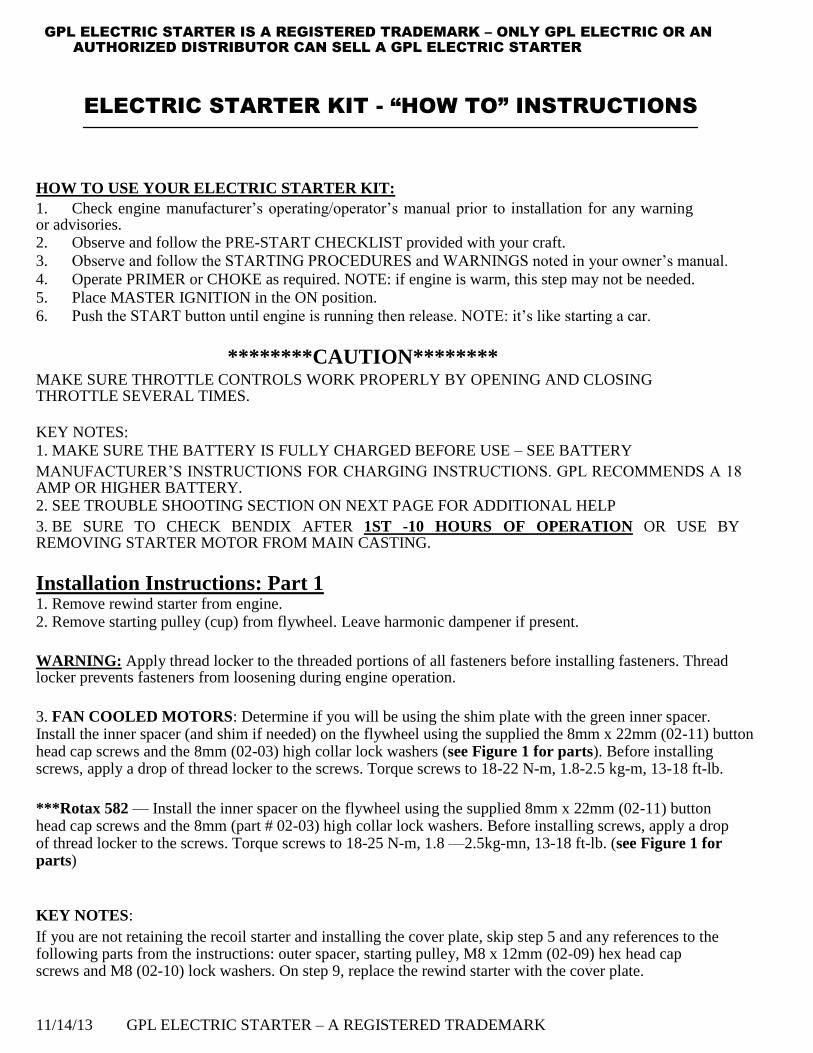
To ensure proper engagement of the BENDIX GEAR to RING GEAR, we have included a SHIM that will be used with the GREEN INNER SPACER on most installations. If the meshing of the BENDIX GEAR and RING GEAR is too tight, remove the SHIM. IT IS RECOMMENDED THE SHIM BE USED UNLESS MESHING ARE TOO TIGHT. IF MESHING IS NOT TIGHT ENOUGH, THE BENDIX GEAR AND RING GEAR WILL WEAR VERY RAPIDLY.
Flywheel, shim & green inner spacer (shim only needed with green inner spacer) (Picture 1)
Shim plate on flywheel (Picture 2)
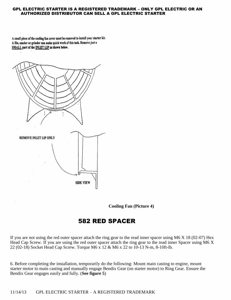
Green spacer, shim plate and fly wheel (Picture 3)
. 11/14/13 GPL ELECTRIC STARTER – A REGISTERED TRADEMARK
GPL ELECTRIC STARTER IS A REGISTERED TRADEMARK – ONLY GPL ELECTRIC OR AN
AUTHORIZED DISTRIBUTOR CAN SELL A GPL ELECTRIC STARTER
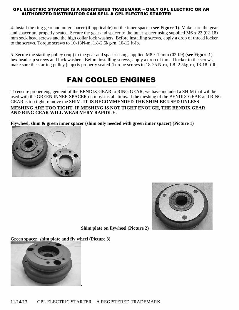
Cooling Fan (Picture 4)
582 RED SPACER
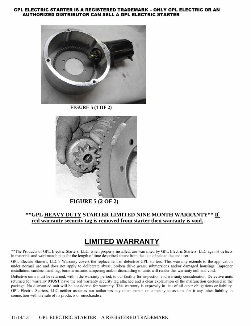
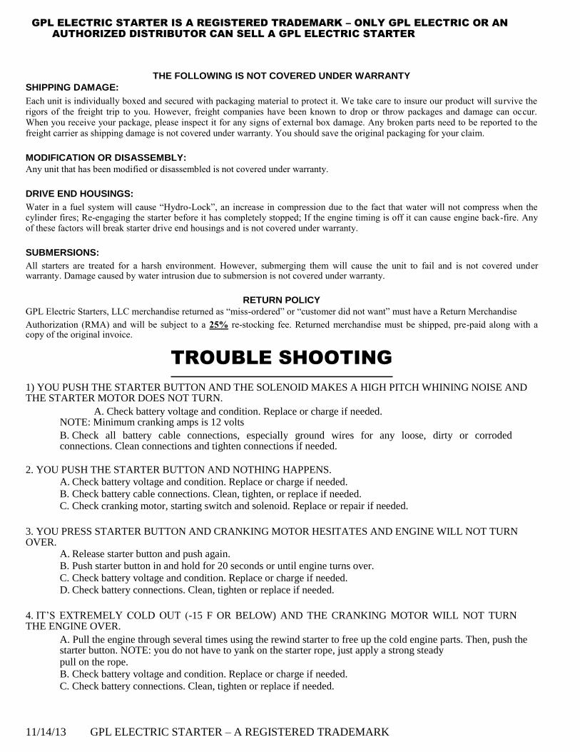
If you are not using the red outer spacer attach the ring gear to the read inner spacer using M6 X 18 (02-07) Hex Head Cap Screw. If you are using the red outer spacer attach the ring gear to the read inner Spacer using M6 X 22 (02-18) Socket Head Cap Screw. Torque M6 x 12 & M6 x 22 to 10-13 N-m, 8-10ft-lb. 6. Before completing the installation, temporarily do the following: Mount main casting to engine, mount starter motor to main casting and manually engage Bendix Gear (on starter motor) to Ring Gear. Ensure the Bendix Gear engages easily and fully. (See figure 5)
11/14/13 GPL ELECTRIC STARTER – A REGISTERED TRADEMARK
GPL ELECTRIC STARTER IS A REGISTERED TRADEMARK – ONLY GPL ELECTRIC OR AN
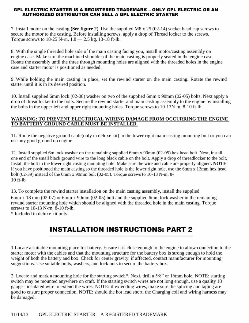
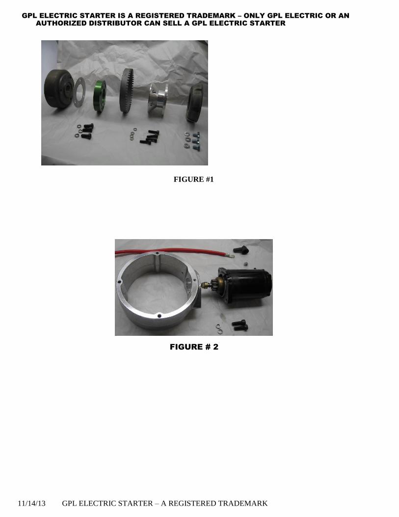
AUTHORIZED DISTRIBUTOR CAN SELL A GPL ELECTRIC STARTER 7. Install motor on the casting (See figure 2). Use the supplied M8 x 25 (02-14) socket head cap screws to secure the motor to the casting. Before installing screws, apply a drop of Thread locker to the screws. Torque screws to 18-25 N-rn, 1.8 — 2.5 kg, 13-18 ft-lb.
8. With the single threaded hole side of the main casting facing you, install motor/casting assembly on engine case. Make sure the machined shoulder of the main casting is properly seated in the engine case. Rotate the assembly until the three through mounting holes are aligned with the threaded holes in the engine case and starter motor is positioned as needed.
9. While holding the main casting in place, set the rewind starter on the main casting. Rotate the rewind starter until it is in its desired position.
10. Install supplied 6mm lock (02-08) washer on two of the supplied 6mm x 90mm (02-05) bolts. Next apply a drop of threadlocker to the bolts. Secure the rewind starter and main casting assembly to the engine by installing the bolts in the upper left and upper right mounting holes. Torque screws to 10-13N-m, 8-10 ft-lb.
WARNING: TO PREVENT ELECTRICAL WIRING DAMAGE FROM OCCURRING THE ENGINE TO BATTERY GROUND CABLE MUST BE INSTALLED.
11. Route the negative ground cable(only in deluxe kit) to the lower right main casting mounting bolt or you can use any good ground on engine.
12. Install supplied 6m lock washer on the remaining supplied 6mm x 90mm (02-05) hex head bolt. Next, install
one end of the small black ground wire to the long black cable on the bolt. Apply a drop of threadlocker to the bolt. Install the bolt in the lower right casting mounting hole. Make sure the wire and cable are properly aligned. NOTE:
if you have positioned the main casting so the threaded hole is the lower right hole, use the 6mm x 12mm hex head
bolt (02-39) instead of the 6mm x 90mm bolt (02-05). Torque screws to 10-13 N-m, 8- 10 ft-lb.
13. To complete the rewind starter installation on the main casting assembly, install the supplied 6mm x 18 mm (02-07) or 6mm x 90mm (02-05) bolt and the supplied 6mm lock washer in the remaining rewind starter mounting hole which should be aligned with the threaded hole in the main casting. Torque screws to 10-13 N-rn, 8-10 ft-lb. * Included in deluxe kit only.
INSTALLATION INSTRUCTIONS: PART 2
1.Locate a suitable mounting place for battery. Ensure it is close enough to the engine to allow connection to the starter motor with the cables and that the mounting structure for the battery box is strong enough to hold the weight of both the battery and box. Check for center gravity, if affected, contact manufacturer for mounting suggestions. Use suitable bolts, washers, and lock nuts to secure the battery box.
2. Locate and mark a mounting hole for the starting switch*. Next, drill a 5/8” or 16mm hole. NOTE: starting switch may be mounted anywhere on craft. If the starting switch wires are not long enough, use a quality 18 gauge - insulated wire to extend the wires. NOTE: if extending wires, make sure the splicing and taping are good to ensure proper connection. NOTE: should the hot lead short, the Charging coil and wiring harness may be damaged.
11/14/13 GPL ELECTRIC STARTER – A REGISTERED TRADEMARK

GPL ELECTRIC STARTER IS A REGISTERED TRADEMARK – ONLY GPL ELECTRIC OR AN
AUTHORIZED DISTRIBUTOR CAN SELL A GPL ELECTRIC STARTER
3. Position the hex nut on the starting switch body so 3/16” of the threads on the starting switch is exposed when the switch is in place. Install the nut/dust cover on the switch. Temporarily hand tighten.
4. Locate and mark a suitable position for the starter solenoid*. Drill a ¼” or 6mm hole. NOTE: remove the paint from the holes. Use the 10-32 screws*, flat washers* and lock nuts* to secure the solenoid. NOTE: solenoid must be grounded. If the mounting position does not ensure good ground, install one end of grounding strap* to mounting bolt and the other end to a suitable ground. NOTE: remove paint to ensure good ground
Included in deluxe kit only.
ELECTRICAL CONNECTION INSTRUCTIONS: PART 3 1. Route RED positive cable* attached to the starting motor to the solenoid. Connect the Red positive cable to one of the copper studs on the solenoid by using one of the ¼ - 20 hex lock nuts. Tighten nut securely and slide rubber boot over nut. NOTE: ensure the cable is well clear of the exhaust system.
2. Locate and mark a suitable mounting position for the regulator*. Mount regulator using 10-32 screws and lock nuts.
3. Route the wiring harness. (See figure 3) The red wire* with the fuse goes to the battery side of the solenoid*. The yellow wire* on the opposite side of the regulator* goes to the starter switch. The blue wire* runs from the starter switch to the small post on the solenoid using the 8-32 hex nut and lock washer and tighten securely. The black wire attaches to the other small post and then to the ground.
4. Install the black rubber boots* on the switch end of the yellow wire* and the blue wires’. Remove starter switch from its mounting position and install the blue and yellow wires*. (See figure 4) Slide the rubber boot onto switch body and reinstall the switch. Then, reinstall the nut/dust cover and tighten securely.
5. Install a black rubber boot* on each end of the long red positive cable*.
6. Starting at the solenoid, route the long red cable to the battery positive (+) post. NOTE: DO NOT CONNECT THE CABLE YET.
7. Working back from the battery towards the solenoid*, use cable ties to secure the cable to the craft. When the cable meets the blue and yellow wires*, use cable ties to bundle the cable and wires together in a neat package.
8. Connect the long red positive cable* to the unused solenoid terminal using one on the ¼- 20 hex lock nuts. Tighten nut securely and slide rubber boot over nut.
9. Install a black rubber insulating boot* on each end of the short red positive cable*. (See figure 2.) Use Vaseline or WD-40 to help slide boots on. Connect one end of the red positive cable to the cranking motor as shown in figure 2. Use the supplied ¼ -20 hex nut to secure the cable to the motor.
10. Starting at the starting motor using cable ties to bundle the yellow wire* and positive cable* together. At the same time routing and securing the bundle away from the exhaust system.
11/14/13 GPL ELECTRIC STARTER – A REGISTERED TRADEMARK
GPL ELECTRIC STARTER IS A REGISTERED TRADEMARK – ONLY GPL ELECTRIC OR AN
AUTHORIZED DISTRIBUTOR CAN SELL A GPL ELECTRIC STARTER NOTE: TAKE YOUR TIME WHEN ROUTING AND BUNDLING THE WIRES AND CABLES. ENSURE THE WIRES AND CABLES WILL NOT BE CUT, CHAFFED, BURNT OR TOUCHED BY ANY HOT ENGINE PARTS. DO A NEAT AND CLEAN JOB.
11. Connect the long red positive cable* to the positive post on the battery. Tighten mounting bolt securely and slide the black rubber boot* over post.
12. Slide the last rubber boot* over the free end of the black ground wire. Next, finish routing the can up to the negative (-) post on the battery.
WARNING: DO NOT CONNECT THE CABLE TO THE BATTERY POST!!
NOTE: Before connecting the battery/engine ground cable to the battery, make the following spark test.
13. Strike the terminal end of the battery ground cable against the negative (-) post on the battery.
NOTE: If any sparks are present DO NOT CONNECT THE BATTERY GROUND CABLE TO THE BATTERY. Instead, recheck the wiring for any connection errors.
14. Connect the ground cable to the negative (-) post. Tighten mounting bolts securely and slide rubber boot down over terminal.
11/14/13 GPL ELECTRIC STARTER – A REGISTERED TRADEMARK
GPL ELECTRIC STARTER IS A REGISTERED TRADEMARK – ONLY GPL ELECTRIC OR AN
AUTHORIZED DISTRIBUTOR CAN SELL A GPL ELECTRIC STARTER
GPL Electric Starter Oil Injection Kit Instructions:
Retaining Pull Start: GPL Part Number 02-63L 1. Before installing main casting, remove flywheel nut and install longer flywheel nut provided in your kit. 2. Complete starter kit installation up to the point where you will be putting the pull starter on 3. Remove the shorter oil line and replace with the oil line provided, check to see if line is long enough 4. Insure the nylon drive shaft is in the square hole in the long nut and on the retaining pin on your oil pump 5. Complete installation of starter kit.
Cover Plate Installation (not retaining pull start): GPL Part Number 02-63C 1. Before installing main casting, remove flywheel nut and install longer flywheel nut provided in your kit. 2. Complete starter kit installation up to the point where you will be putting the pull starter on 3. Remove the oil pump from your pull starter 4. Mount the pump to the cover plate using the provided 10-32 screws and lock nuts 5. Insure the nylon drive shaft is in the square hole in the long nut and on the retaining pin on your oil pump 6. Complete installation of starter kit
Final check To ensure there is no air in the oil lines we recommend pre-mixing oil with the first gallon of fuel. Mark the oil tank and ensure the level goes down after using the first gallon of fuel.
FINAL CHECK LIST:
**ALL NUTS/BOLTS ARE TIGHT
**WIRING IS OUT OF THE WAY OF POSSIBLE DAMAGE **BATTERY VENT TUBE (if available) IS NOT PINCHED. **RE WIND STARTER ROPE PULLS EASILY (if available).
Your electric starter is now installed. Congratulations and happy starting from everyone at GPL Electric Starters.
TO ORDER STARTER KITS OR PARTS PLEASE SEE OUR WEBSITE:
WWW.GPLELECTRICSTARTERS.COM 11/14/13 GPL ELECTRIC STARTER – A REGISTERED TRADEMARK
GPL ELECTRIC STARTER IS A REGISTERED TRADEMARK – ONLY GPL ELECTRIC OR AN
AUTHORIZED DISTRIBUTOR CAN SELL A GPL ELECTRIC STARTER
FIGURE #1
FIGURE # 2
11/14/13 GPL ELECTRIC STARTER – A REGISTERED TRADEMARK

GPL ELECTRIC STARTER IS A REGISTERED TRADEMARK – ONLY GPL ELECTRIC OR AN
AUTHORIZED DISTRIBUTOR CAN SELL A GPL ELECTRIC STARTER
FIGURE 3
FIGURE 4
11/14/13 GPL ELECTRIC STARTER – A REGISTERED TRADEMARK
GPL ELECTRIC STARTER IS A REGISTERED TRADEMARK – ONLY GPL ELECTRIC OR AN
AUTHORIZED DISTRIBUTOR CAN SELL A GPL ELECTRIC STARTER
FIGURE 5 (1 OF 2)
FIGURE 5 (2 OF 2)
**GPL HEAVY DUTY STARTER LIMITED NINE MONTH WARRANTY** If red warranty security tag is removed from starter then warranty is void.
LIMITED WARRANTY **The Products of GPL Electric Starters, LLC, when properly installed, are warranted by GPL Electric Starters, LLC against defects in materials and workmanship as for the length of time described above from the date of sale to the end user. GPL Electric Starters, LLC’s Warranty covers the replacement of defective GPL starters. This warranty extends to the application under normal use and does not apply to deliberate abuse, broken drive gears, submersions and/or damaged housings. Improper installation, careless handling, burnt armatures tampering and/or dismantling of units will render this warranty null and void. Defective units must be returned, within the warranty period, to our facility for inspection and warranty consideration. Defective units
returned for warranty MUST have the red warranty security tag attached and a clear explanation of the malfunction enclosed in the
package. No dismantled unit will be considered for warranty. This warranty is expressly in lieu of all other obligations or liability.
GPL Electric Starters, LLC neither assumes nor authorizes any other person or company to assume for it any other liability in
connection with the sale of its products or merchandise. 11/14/13 GPL ELECTRIC STARTER – A REGISTERED TRADEMARK
GPL ELECTRIC STARTER IS A REGISTERED TRADEMARK – ONLY GPL ELECTRIC OR AN
AUTHORIZED DISTRIBUTOR CAN SELL A GPL ELECTRIC STARTER
THE FOLLOWING IS NOT COVERED UNDER WARRANTY SHIPPING DAMAGE: Each unit is individually boxed and secured with packaging material to protect it. We take care to insure our product will survive the rigors of the freight trip to you. However, freight companies have been known to drop or throw packages and damage can occur. When you receive your package, please inspect it for any signs of external box damage. Any broken parts need to be reported to the freight carrier as shipping damage is not covered under warranty. You should save the original packaging for your claim.
MODIFICATION OR DISASSEMBLY: Any unit that has been modified or disassembled is not covered under warranty.
DRIVE END HOUSINGS: Water in a fuel system will cause “Hydro-Lock”, an increase in compression due to the fact that water will not compress when the cylinder fires; Re-engaging the starter before it has completely stopped; If the engine timing is off it can cause engine back-fire. Any of these factors will break starter drive end housings and is not covered under warranty.
SUBMERSIONS: All starters are treated for a harsh environment. However, submerging them will cause the unit to fail and is not covered under warranty. Damage caused by water intrusion due to submersion is not covered under warranty.
RETURN POLICY
GPL Electric Starters, LLC merchandise returned as “miss-ordered” or “customer did not want” must have a Return Merchandise Authorization (RMA) and will be subject to a 25% re-stocking fee. Returned merchandise must be shipped, pre-paid along with a copy of the original invoice.
TROUBLE SHOOTING
1) YOU PUSH THE STARTER BUTTON AND THE SOLENOID MAKES A HIGH PITCH WHINING NOISE AND THE STARTER MOTOR DOES NOT TURN.
A. Check battery voltage and condition. Replace or charge if needed. NOTE: Minimum cranking amps is 12 volts B. Check all battery cable connections, especially ground wires for any loose, dirty or corroded connections. Clean connections and tighten connections if needed.
2. YOU PUSH THE STARTER BUTTON AND NOTHING HAPPENS.
A. Check battery voltage and condition. Replace or charge if needed. B. Check battery cable connections. Clean, tighten, or replace if needed.
C. Check cranking motor, starting switch and solenoid. Replace or repair if needed.
3. YOU PRESS STARTER BUTTON AND CRANKING MOTOR HESITATES AND ENGINE WILL NOT TURN OVER.
A. Release starter button and push again.
B. Push starter button in and hold for 20 seconds or until engine turns over. C. Check battery voltage and condition. Replace or charge if needed. D. Check battery connections. Clean, tighten or replace if needed.
4. IT’S EXTREMELY COLD OUT (-15 F OR BELOW) AND THE CRANKING MOTOR WILL NOT TURN THE ENGINE OVER.
A. Pull the engine through several times using the rewind starter to free up the cold engine parts. Then, push the starter button. NOTE: you do not have to yank on the starter rope, just apply a strong steady pull on the rope. B. Check battery voltage and condition. Replace or charge if needed. C. Check battery connections. Clean, tighten or replace if needed.
11/14/13 GPL ELECTRIC STARTER – A REGISTERED TRADEMARK