Embed Size (px)
Citation preview
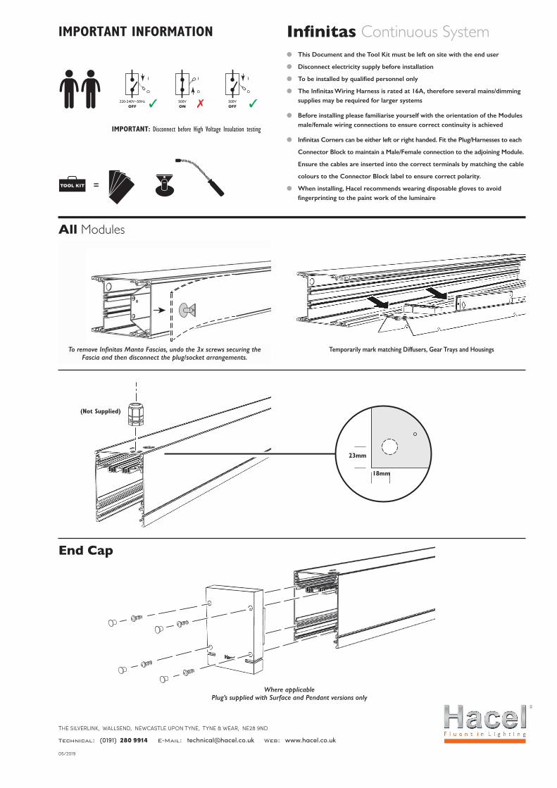
Infinitas Continuous Systeml This Document and the Tool Kit must be left on site with the end user
l Disconnect electricity supply before installation
l To be installed by qualified personnel only
l The Infinitas Wiring Harness is rated at 16A, therefore several mains/dimming supplies may be required for larger systems
l Before installing please familiarise yourself with the orientation of the Modules male/female wiring connections to ensure correct continuity is achieved
l Infinitas Corners can be either left or right handed. Fit the Plug/Harnesses to each
Connector Block to maintain a Male/Female connection to the adjoining Module.
Ensure the cables are inserted into the correct terminals by matching the cable
colours to the Connector Block label to ensure correct polarity.
l When installing, Hacel recommends wearing disposable gloves to avoid fingerprinting to the paint work of the luminaire
220-240V~50HzOFF
500VON
500VOFF
TOOL KIT
220-240V~50HzOFF
500VON
500VOFF
TOOL KIT
IMPORTANT: Disconnect before High Voltage Insulation testing
All Modules
Temporarily mark matching Diffusers, Gear Trays and HousingsTo remove Infinitas Manta Fascias, undo the 3x screws securing the Fascia and then disconnect the plug/socket arrangements.
(Not Supplied)
23mm
18mm
End Cap
Where applicable Plug’s supplied with Surface and Pendant versions only
THE SILVERLINK, WALLSEND, NEWCASTLE UPON TYNE, TYNE & WEAR, NE28 9ND
Technical: (0191) 280 9914 E-Mail: [email protected] Web: www.hacel.co.uk
05/2019
IMPORTANT INFORMATION
2 . Hacel . Fluent in Lighting
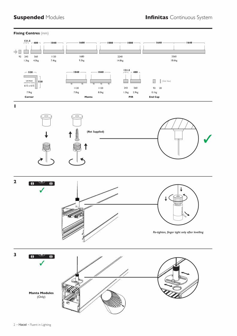
Suspended Modules Infinitas Continuous System
Fixing Centres (mm)
3360
1640 1640
2240
1080 1080
1680
1600
1120
1040
560
480
24392
18.6kg14.8kg9.3kg7.4kg
1040 1040
4.0kg1.3kg
121.5
560
480
243
2.9kg 0.1kg1.3kg
121.5528
528Left Hand(viewed from above)
615 x 615
7.9kg
Corner Manta PIR End Cap
1120
7.0kg
1120
8.0kg
92 20
(Side View)
122
1
2
3
Screws
Arrows
Suspension
Screws
Arrows
Suspension
(Not Supplied)
Re-tighten, finger tight only after levelling
220-240V~50HzOFF
500VON
500VOFF
TOOL KIT
220-240V~50HzOFF
500VON
500VOFF
TOOL KIT
Manta Modules(Only)
Screws
Arrows
Suspension
Screws
Arrows
Suspension
Infinitas . Hacel . 3
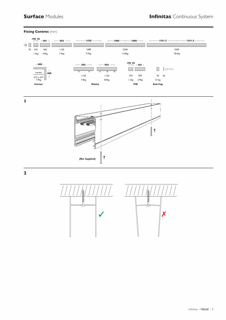
Surface Modules Infinitas Continuous System
Fixing Centres (mm)
1541.5 1541.51000 10001428856
3360224016801120560243
18.6kg14.8kg9.3kg7.4kg
856
4.0kg1.3kg
401198 45
401198 45400
400Left Hand(viewed from above)
615 x 615
856
92
122
560243
2.9kg 0.1kg1.3kg7.9kg
Corner Manta PIR End Cap
1120
7.0kg
1120
8.0kg
92 20
(Side View)
1
2
(Not Supplied)
4 . Hacel . Fluent in Lighting
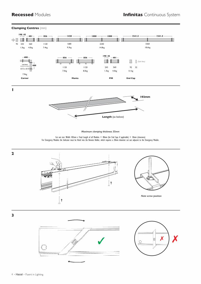
Recessed Modules Infinitas Continuous System
Clamping Centres (mm)
1541.5 1541.51000 10001428856401
3360224016801120560
400
400Left Hand(viewed from above)
615 x 615
243
18.6kg14.8kg9.3kg7.4kg4.0kg1.3kg
198 45
401
560243
4.0kg1.3kg
198 45856
1120
7.0kg
1120
8.0kg
856
92
122
0.1kg
7.9kg
Corner Manta PIR End Cap
92 32
(Side View)
1
2
3
Note screw position
Maximum clamping thickness 35mm
Cut out size: Width 102mm x Total Length of all Modules + 40mm (for End Caps if applicable) + 10mm (clearance)For Emergency Modules the Indicator must be fitted into the Remote Holder, which requires a 20mm diameter cut out adjacent to the Emergency Module.
Length (as below)
102mm
Screws
Arrows
Suspension
Screws
Arrows
Suspension
Infinitas . Hacel . 5
Screws
Arrows
Suspension
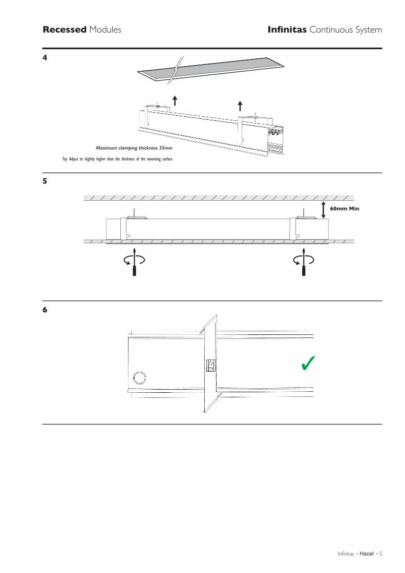
Recessed Modules Infinitas Continuous System
5
4
6
Maximum clamping thickness 35mm
Tip: Adjust to slightly higher than the thickness of the mounting surface
60mm Min
6 . Hacel . Fluent in Lighting
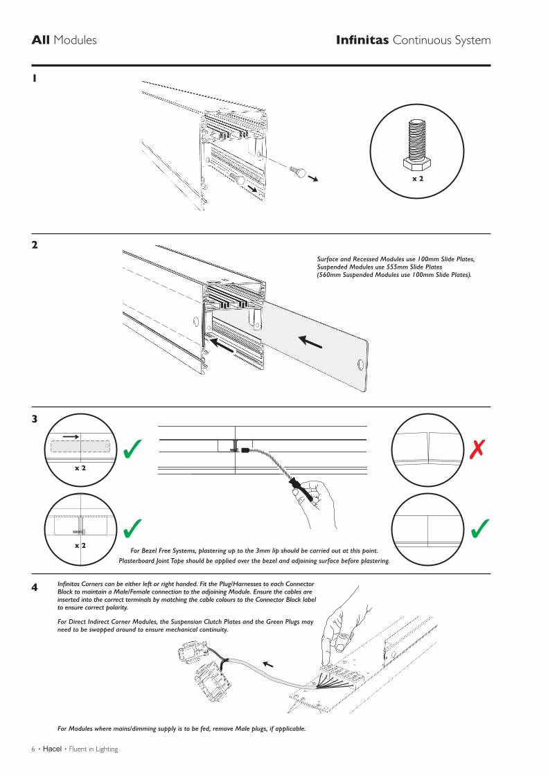
All Modules Infinitas Continuous System
2
1
3
4
For Bezel Free Systems, plastering up to the 3mm lip should be carried out at this point.Plasterboard Joint Tape should be applied over the bezel and adjoining surface before plastering.
Infinitas Corners can be either left or right handed. Fit the Plug/Harnesses to each Connector Block to maintain a Male/Female connection to the adjoining Module. Ensure the cables are inserted into the correct terminals by matching the cable colours to the Connector Block label to ensure correct polarity.
For Direct Indirect Corner Modules, the Suspension Clutch Plates and the Green Plugs may need to be swapped around to ensure mechanical continuity.
For Modules where mains/dimming supply is to be fed, remove Male plugs, if applicable.
Screws
Arrows
Suspension
x 2
x 2
x 2
Screws
Arrows
Suspension
Screws
Arrows
Suspension
Screws
Arrows
Suspension
Screws
Arrows
Suspension
Surface and Recessed Modules use 100mm Slide Plates, Suspended Modules use 555mm Slide Plates (560mm Suspended Modules use 100mm Slide Plates).
Infinitas . Hacel . 7
All Modules Infinitas Continuous System
6
5
7
8
= =
Screws
Arrows
Suspension
Screws
Arrows
Suspension
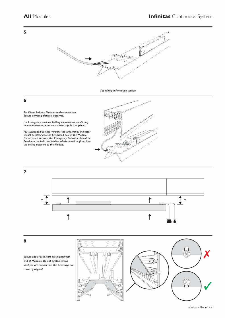
See Wiring Information section
For Direct Indirect Modules make connection.Ensure correct polarity is observed.
For Emergency versions, battery connections should onlybe made when a permanent mains supply is in place.
For Suspended/Surface versions the Emergency Indicator should be fitted into the pre-drilled hole in the Module. For recessed versions the Emergency Indicator should be fitted into the Indicator Holder which should be fitted into the ceiling adjacent to the Module.
Ensure end of reflectors are aligned with end of Modules. Do not tighten screws until you are certain that the Geartrays are correctly aligned.
8 . Hacel . Fluent in Lighting
500VOFF
All Modules Infinitas Continuous System
10
9
11
12
220 - 240VON
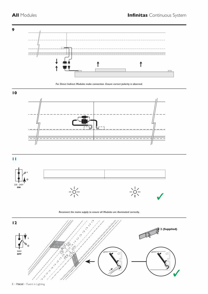
Reconnect the mains supply to ensure all Modules are illuminated correctly.
For Direct Indirect Modules make connection. Ensure correct polarity is observed.
x 2 (Supplied)
Infinitas . Hacel . 9
All Modules Infinitas Continuous System
13
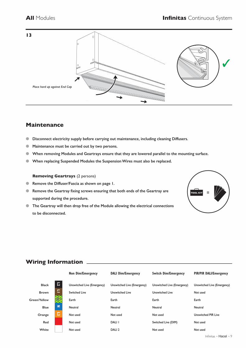
Place hard up against End Cap
Maintenance
l Disconnect electricity supply before carrying out maintenance, including cleaning Diffusers.
l Maintenance must be carried out by two persons.
l When removing Modules and Geartrays ensure that they are lowered parallel to the mounting surface.
l When replacing Suspended Modules the Suspension Wires must also be replaced.
Removing Geartrays (2 persons)
l Remove the Diffuser/Fascia as shown on page 1.
l Remove the Geartray fixing screws ensuring that both ends of the Geartray are
supported during the procedure.
l The Geartray will then drop free of the Module allowing the electrical connections
to be disconnected.
220-240V~50HzOFF
500VON
500VOFF
TOOL KIT
Non Dim/Emergency
Unswitched Live (Emergency)
Switched Live
Earth
Neutral
Not used
Not used
Not used
DALI Dim/Emergency
Unswitched Live (Emergency)
Unswitched Live
Earth
Neutral
Not used
DALI 1
DALI 2
Switch Dim/Emergency
Unswitched Live (Emergency)
Unswitched Live
Earth
Neutral
Not used
Switched Live (DIM)
Not used
PIR/PIR DALI/Emergency
Unswitched Live (Emergency)
Not used
Earth
Neutral
Unswitched PIR Live
Not used
Not used
Black
Brown
Green/Yellow
Blue
Orange
Red
White
L2L1
NL3
Wiring Information
Screws
Arrows
Suspension

HACEL LIGHTING LTD.THE SILVERLINKWALLSENDNEWCASTLE UPON TYNETYNE & WEARNE28 9NDUK
For further Technical information
Tel: 0191 280 9911Then choose the fol lowing number :
Technical Dial: 4
www.hacel.co.uk
05/2019


![SERIES INFINITAS[1]](https://img.pdfslide.net/doc/110x75/5571f96349795991698f77f1/series-infinitas1.jpg)