Embed Size (px)
Citation preview

Copyright 2002-2017 SRM Enterprises, Inc. Patent #7,270,279 1
It is important you read this entire assembly manual before putting your track together. We need to be notified of damaged/missing parts within 30 days of the delivery of your order.
Important notes on your BestTrack® Pinewood Derby® Track
Safety Precautions: If needed, smooth edges with emery cloth or a file. Do not use with any timer or electrical device that uses household current to power the timer or device unless using a step down transformer to bring the voltage to a safe level. Because this is a metal track, proper precautions must be used to prevent bare wires from coming in contact with the metal components of the track which could cause shorting or electrocution. Use only low voltage timers, etc. on this track to assure the safety of all users of the track. Please keep all plastic guards, end caps, etc. in place to protect edges. Do not stand or climb or allow others to stand or climb on the track or any part of the stand.
It is normal for one or both sidewalls of the track lane with the curve formed in it to be rolled inward towards the center of the lane. This is due to the manufacturing process and will not affect the function of the track. This is normal and will not affect the speed of the cars or the fairness of the race in any way.
Recommended tools for first time assembly: Hammer, carpenter’s square, screwdrivers (both flat & Phillips), electric hand drill (may be needed),
7/16” socket wrench* or adjustable wrench*, 2 pair of pliers*.
*The only tools typically needed for 2nd & subsequent assembly.
Please Read All of the Instructions Completely! Assembly Video Available Online! Unpack and layout lanes: We suggest you lay out all of the lanes in line before proceeding. Please note the Bumps and Indentations shown in the diagram below. These need to all go the same direction, with all of the bumps on the sides of the lanes facing one side of the track and all of the indentations facing the other side of the track. (See picture below). LIFT/LEVEL or LEVEL KIT! If you have purchased one of these kits, you will want to install the mounting bolts as you assemble your track to save time later. Please read the kit instructions before assembling your track. Note that the sides of each lane are designed to mate up with the one beside it and interlock. (See diagram below) Make sure the lanes are all lined up in the same direction, as stated above. Use the included file in case you need to remove a burr or to round off a corner.
BestTrack® Pinewood Derby® Tracks by SRM Enterprises, Inc. P.O. Box 53 Forest City, IA 50436 Phone: 641-585-2299

Copyright 2002-2017 SRM Enterprises, Inc. Patent #7,270,279 2
Please use the packing list below as a guide to the quantity of each part included in your track.
Track Size
Packing ListPart Names 235 242 249 335 342 349 435 442 449 635 642 649 835 842 849
Stand Frame Kit 1 1 1 1 1 1 1 1 1 1 1 1 2 2 2
Lever Ass'y 1 1 1 1 1 1 1 1 1 1 1 1 1 1 1
Springs 3 3 3 3 3 3 3 3 3 3 3 3 3 3 3
Stand Hinge 7" (2, 4, 6, & 8 lane) 2 2 2 2 2 2 2 2 2 4 4 4
Stand Hinge 10.5" (3 & 5 lane) 2 2 2
Start Ass'y for 2 lanes 7.5" 1 1 1
Start Ass'y for 3 lanes 11" 1 1 1
Start Ass'y for 4 lanes 14.5" 1 1 1
Start Ass'y for 6 lanes 21.5" 1 1 1
Start Ass'y for 8 lanes 28.5" 1 1 1
#10-24 screw & nut 2 2 2 3 3 3 4 4 4 6 6 6 8 8 8
Connector Angle for 2 lanes 7" 11 13 15
Connector Angle for 3 lanes 10.5" 11 13 15
Connector Angle for 4 lanes 14" 11 13 15
Connector Angle for 6 lanes 21" 16 19 22
Connector Angle for 8 lanes 28" 16 19 22
Spring Clip (Binder Clip) 12 14 16 12 14 16 18 21 24 18 21 24 24 28 32
3/16" diameter knurled dowel pin 18 22 26 26 32 38 34 42 50 50 62 74 66 82 98
1/4" - 20 bolt 1/2" long 74 82 90 104 116 128 126 142 158 244 281 312 328 376 424
1/4" - 20 nut 74 82 90 104 116 128 126 142 158 244 281 312 328 376 424
7' Starting Lane 2 2 2 3 3 3 4 4 4 6 6 6 8 8 8
41" Curved Lane 2 2 2 3 3 3 4 4 4 6 6 6 8 8 8
7' Standard Straight Lane 6 8 10 9 12 15 12 16 20 18 24 30 24 32 40
Braking Section 40" 2 2 2 3 3 3 4 4 4 6 6 6 8 8 8
Braking Section Rubber Strip 40" 2.5 2.5 2.5 4 4 4 5 5 5 7 7 7 9 9 9
Stand Bottom Angle End Cap 2 2 2 2 2 2 2 2 2 2 2 2 4 4 4
Deburring File 1 1 1 1 1 1 1 1 1 1 1 1 1 1 1
Curve Support Leg (Short) 2 2 2 2 2 2 2 2 2 2 2 2 2 2 2
Curve Leg Vinyl Cap 2 2 2 2 2 2 2 2 2 2 2 2 2 2 2
3/16" Dia. Drill Bit 1 1 1 1 1 1 1 1 1 1 1 1 1 1 1
Plastic Top Cap 7" 1 1 1 2 2 2 4 4 4
Plastic Top Cap 10" 1 1 1 2 2 2
Plastic Darts for Top Cap 3 3 3 4 4 4 6 6 6 8 8 8 12 12 12
Starting Bolt Vinyl Cover 2 2 2 3 3 3 4 4 4 6 6 6 8 8 8
Example: Number of lanes and length. A 235 track is 2 lanes wide by 35 ft. long.
Dowel Pin Installation: Important! Be careful not to tap too hard on the end of the pin as it may “mushroom” out making it difficult to join the next section together with it. We suggest using a soft faced hammer (brass) to prevent damage to the pins, or use a block of hard wood between the hammer and the pin. Drill Bit We have included a 3/16” diameter drill bit to use when assembling your track the first time. Use this bit to carefully ream out the two outer dowel pin holes in the end of the lanes if the smooth part of the knurled dowel pin will not slide into the dowel pin holes easily. Using an electric drill, ream only enough to be able to tap in the pins easily. Also, lightly ream the dowel pin holes on the adjoining lanes with the drill bit to allow the sections to slide together easily. The dowel pins have a knurl, or raised rough surface in the middle part of the pin. Tap them in gently until the knurled part is completely in the end of the lane leaving only the 3/16” long smooth part of the pin sticking out of the end of the lane.

Copyright 2002-2017 SRM Enterprises, Inc. Patent #7,270,279 3
The knurled dowel pins only go in one end of each straight lane and curve lane. The last section of track and the stop section will not have dowel pins installed in them.
Special Notes for 6 and 8 lane tracks: Dowel Pins: Please note that although we provide enough dowels to use 2 per lane per joint, we have found that to ease assembly, you can use one dowel per lane on larger tracks, omitting half of the dowels.
Install 3/16” diameter knurled dowel pins, one in each of the outside corners at the lower end of each of the starting lanes. (The start lanes have an oval slot punched through the middle of the lane towards the top end of the track.) The two center holes of each lane do not need dowel pins due to the tight manufacturing tolerances used when we produce the lanes. Using a hammer, tap the pins in leaving only the smooth part of the pin 3/16” out. (See picture)
Install knurled pins in the outside corners of each curve lane in the curve section and in the outside corners of each straight lane on the ends facing the stop section.
Lay the curved lanes upside down. Note the bumps and indentations on the sides of the curve lanes. Be sure they are all running the same direction. Use the spring clips to hold the lanes together side by side while assembling. Slide the 1/2” long bolts into the bolt slots on the bottom of the curve section about 1/2” in from the end of the lane. Line up the bolts with the holes in the connector angle with the edge of the angle 1/8” in from the end. Attach the nuts, but do not tighten them yet. Flush up the ends using a carpenters square, and then you can tighten up the nuts. Slide in 2 more bolts on each side in the outer slots for the curve support legs as shown. Adjust location of legs to have the bottom end of the curve section flat & level to be able to attach to the straight lanes. Now place the black vinyl end caps on the curve legs as shown. The location is approximately 3” from the end of the curved lane to the edge of the leg bracket. (If there is any mismatch in the top ends of the curves it can be adjusted in the start lanes and start mechanism.) Attach the connector angle at other end of curve section in the same manner. Be sure the edge of the connector angles are 1/8” in from the end of the lane. Now you can remove the spring clips.
Copyright 2002-2017 SRM Enterprises, Inc. Patent #7,270,279 4
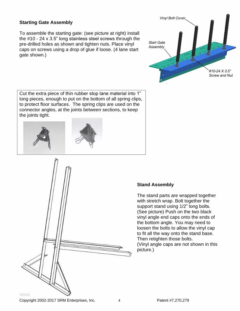
Starting Gate Assembly To assemble the starting gate: (see picture at right) install the #10 - 24 x 3.5” long stainless steel screws through the pre-drilled holes as shown and tighten nuts. Place vinyl caps on screws using a drop of glue if loose. (4 lane start gate shown.)
Cut the extra piece of thin rubber stop lane material into 1” long pieces, enough to put on the bottom of all spring clips, to protect floor surfaces. The spring clips are used on the connector angles, at the joints between sections, to keep the joints tight.
Stand Assembly The stand parts are wrapped together with stretch wrap. Bolt together the support stand using 1/2” long bolts. (See picture) Push on the two black vinyl angle end caps onto the ends of the bottom angle. You may need to loosen the bolts to allow the vinyl cap to fit all the way onto the stand base. Then retighten those bolts. (Vinyl angle caps are not shown in this picture.)

Copyright 2002-2017 SRM Enterprises, Inc. Patent #7,270,279 5
Straight Lane assembly. For a two lane track lay two lanes side by side and upside down, for a three lane track lay three lanes side by side and upside down, etc. Be sure the bumps and indentations are all going the same direction. Use the spring clips to help hold the lanes together side by side for assembly. Slide the ½” long bolts into the slots located on the bottom of the lanes and line up the connector angles with the bolts. Be sure the connector angles are 1/8” in from each end of the lane and then tighten nuts. Remove the spring clips once it is all tightened. If you have a timer, check the mounting instructions before building the timer section. Once all of your sections have been assembled, and while they are still upside down, line up the dowel pins with the dowel pin holes in each of the other straight sections and slide them together to check for alignment.
NOTE: NEVER USE A HAMMER ON THE ENDS OF THE LANES, YOU SHOULD ALWAYS BE ABLE TO WIGGLE AND PUSH THE LANES TOGETHER.
Starting lane assembly.
The starting lanes are the straight lanes with an oval slot towards the top end. To assemble the starting lanes: lay the lanes upside down and use the spring clips to hold them together temporarily while you are attaching the connector angles. Slide the 1/2” bolts into the bottom of the lanes (the end away from the slots) and line up the bolts with the holes in the connector angles; make sure the lanes are flush and that the connector angles are 1/8” in from the end of the lane. Now you can tighten the nuts. Slide in the bolts in for the middle hinge. (See picture) The middle hinge is located approximately 32-1/4” from the end of the lane. Line up hinge holes with bolts and tighten nuts. Slide bolts in for the top hinge, 19” from the top end of the lanes and attach top hinge. (See picture) IMPORTANT: Slide two bolts into the first bolt slot of the outside lane. (See picture)
These bolts will be used later for the starting lever assembly. If you have the Champ Timer, be sure to slide one extra bolt into the 3rd slot from the lever side, just below the start gate, and one below the start lever. These are for the start gate and reset switch brackets. Slide bolts in for the starting gate assembly, 6” from the top of the lanes, attach starting gate, and tighten the bolts. It is very important to get this square with the track. You can use a carpenter’s square along side of the track and across the starting pins.
You can now attach the starting lanes to the stand while the starting lane section is upside down. (See picture: 4 - lane track shown)
8 Lane Tracks: Please note that 8 lane tracks will have 2 stand assemblies. Attach one stand to lanes 1 and 2 and the other to lanes 7 and 8. You may need to adjust the position of the stand bases so that they do not interfere with each other.
4-Lane Track Shown
Copyright 2002-2017 SRM Enterprises, Inc. Patent #7,270,279 6
Next slide the curved lane section into the straight lane section and attach the spring clips over the connector angles at the joint. Adjust the curve legs if necessary by loosening the attachment bolts and sliding their location to make sure the end of the curve section aligns parallel with the straight sections. Now attach the starting lanes to the curved lanes and attach the spring clips over the connector angles at the joint. The top of the starting lanes are approx. 47”- 48” off the floor when finished. Look at the joint between the curved lanes and the starting lanes to make sure the lanes are lined up, if not, loosen the top hinge and slide the stand frame to adjust and retighten the nuts. Note: If the dowels don’t line up perfectly, loosen up a few of the nuts on the connector angle on the starting lane section, slide the sections together, retighten the nuts, and then attach the spring clips.
Now attach the starting lever holder to the track using the two bolts that are already in the top section in front of the starting assembly. Slide a ½” long bolt in the right side slot at the top of the starting lane, approx. 1” from the end. Tighten with nut and attach the springs as shown for the starting assembly, then add a second nut to hold the spring in place. For 4 to 8 lane tracks, attach two springs to the start gate in this manner, one at each end of the start assembly. Now attach the lever spring. (See picture)
Next attach your timer or draw a finish line at the end of your track. Use a carpenter’s square to get a straight finish line or to line up timer sensors. To fine tune your starting gate, put a straight edge across the starting pins and measure back, making sure the gate is square with the track; if not, loosen the nuts on the starting
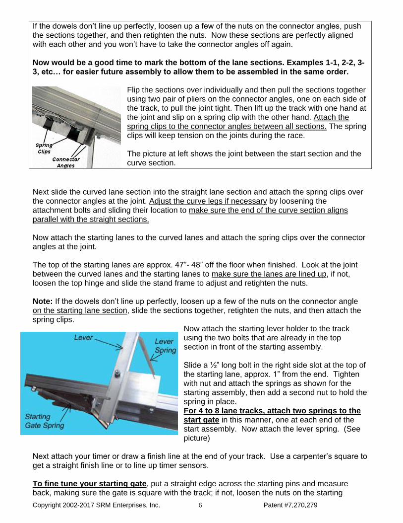
If the dowels don’t line up perfectly, loosen up a few of the nuts on the connector angles, push the sections together, and then retighten the nuts. Now these sections are perfectly aligned with each other and you won’t have to take the connector angles off again. Now would be a good time to mark the bottom of the lane sections. Examples 1-1, 2-2, 3-3, etc… for easier future assembly to allow them to be assembled in the same order.
Flip the sections over individually and then pull the sections together using two pair of pliers on the connector angles, one on each side of the track, to pull the joint tight. Then lift up the track with one hand at the joint and slip on a spring clip with the other hand. Attach the spring clips to the connector angles between all sections. The spring clips will keep tension on the joints during the race. The picture at left shows the joint between the start section and the curve section.
Copyright 2002-2017 SRM Enterprises, Inc. Patent #7,270,279 7
assembly and make your adjustments and retighten the nuts. If one of the starting pins is not quite in line just take your thumb and push it into place. When disassembling your track, you only remove the spring clips. Do NOT remove the connector angles as this will speed up your assembly for the next race. To detach the stand, only remove the four bolts on the middle and top hinge. Do NOT remove the hinges from the track. Do NOT remove the starting assembly from the track. (You may want to remove the 3.5” long screws so they won’t get damaged in storage) Plastic Top End Caps Plastic top caps have been included for the top end of the track. Attach these caps to the top end of the track across all of the lanes, covering the end of the track lanes. Use the enclosed plastic fasteners to hold the caps on by pushing them through the cap into the holes on the ends of the lanes. Do not hit them hard with a hammer as this can crack them. This is to prevent accidental bumping into the edges at the end of the track.
Stop Section End Caps End caps are also provided for the end of the stop section. Please attach them in the same manner.
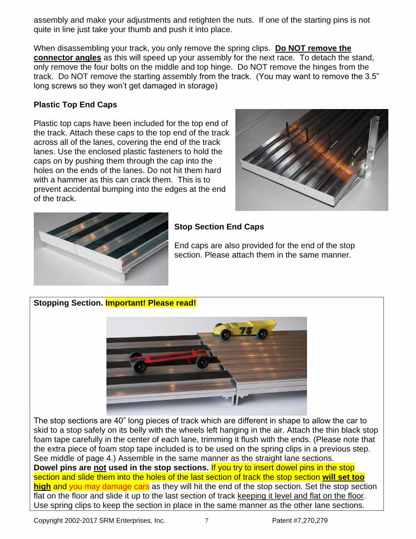
Stopping Section. Important! Please read!
The stop sections are 40” long pieces of track which are different in shape to allow the car to skid to a stop safely on its belly with the wheels left hanging in the air. Attach the thin black stop foam tape carefully in the center of each lane, trimming it flush with the ends. (Please note that the extra piece of foam stop tape included is to be used on the spring clips in a previous step. See middle of page 4.) Assemble in the same manner as the straight lane sections. Dowel pins are not used in the stop sections. If you try to insert dowel pins in the stop section and slide them into the holes of the last section of track the stop section will set too high and you may damage cars as they will hit the end of the stop section. Set the stop section flat on the floor and slide it up to the last section of track keeping it level and flat on the floor. Use spring clips to keep the section in place in the same manner as the other lane sections.

Copyright 2002-2017 SRM Enterprises, Inc. Patent #7,270,279 8
Cleaning – Simple Green spray works well to remove fingerprints from the aluminum surfaces. Window cleaners work also, but are not as effective. Avoid cleaners with ammonia. Brush or vacuum stop section foam. Avoid cleaning stop foam with other cleaners, including soap. Small scratches or marks from shipping can be removed with 400 – 600 grit wet/dry sandpaper. Rub along the length of the lane, not across the lane. Use the included file in case you need to remove a burr or to round off a corner. Lifetime Warranty
Your BestTrack Pinewood Derby Track is covered by a lifetime warranty against manufacturing defects and warping. This warranty does not cover damage due to misuse or abuse whether accidental or intentional. Discoloration or spotting due to liquids sitting on the track surface is not covered. Any needed parts will be shipped to the initial delivery address. All product warranty replacement parts will ship by regular ground or US mail; we do not cover expedited shipping. For product shipping damage/missing parts replacement coverage, we need to be notified of any product shipping damage/missing parts within 30 days after the delivery of your order. The notification should include the damage incurred and replacement parts needed. Any needed parts will be shipped to the initial delivery address. All product replacement
parts will ship by regular ground or US mail; we do not cover expedited shipping.
For product shipping damage replacement coverage, we need to be notified of any product shipping damage upon the initial delivery of your order. The notification should include the damage incurred and the replacement parts needed. We reserve the right to request pictures of the damage. If deemed by us to have incurred the damage during shipping, such replacement parts would need to be shipped by us to the order’s initial delivery location. We reserve the right to request the return of any parts replaced. We will not cover any additional shipping charges to or from any other location. The product shipping damage replacement coverage is only valid for the order’s initial delivery location, and any damage will need to be inspected by the initial carrier prior to moving the shipment to any other location. If shipping damage is found to exist after forwarded to other locations, such damage will not be covered by our shipping damage replacement coverage.
BestTrack®
by SRM Enterprises, Inc. P.O. Box 53, Forest City, IA 50436
Phone: 641-585-2299

Copyright 2002-2017 SRM Enterprises, Inc. Patent #7,270,279 9
Other Products for BestTrack® From SRM Enterprises, Inc.
BestTrack ® Leveling Kit
The BestTrack ® Leveling Kit allows you to
adjust each section of track independently to compensate for uneven floors. The ONLY Leveling Kit available for any Pinewood
Derby track. If you are going to run your track on a smooth level floor such as a gym floor you will probably not need this kit.
Our Leveling Kit consists of easily attached leveling feet for all sections of track
including the stand, curve and stop section.
BestTrack ® Lift/Leveling Kit
The BestTrack ® Lift & Leveling Kit elevates your track about 18" off the floor allowing better viewing of the race from all angles.
Our Lift/Leveling Kit consists of easily attached aluminum legs that spin on or off in seconds. Also included are a
stand extension, curve leg extensions, and poly leveling feet. Each straight section has four legs to stand independently. Legs can be positioned anywhere along the length of the straight sections. Each leg has a threaded leveling foot that can be adjusted for uneven floors. Leveling feet are also provided for the stand and curve legs. Legs and leveling feet are also included for the stop section. Check out our website for new products, accessories, options and pricing.
BestTrack®
by SRM Enterprises, Inc. P.O. Box 53, Forest City, IA 50436
Phone: 641-585-2299

Copyright 2002-2017 SRM Enterprises, Inc. Patent #7,270,279 10
Track Extensions and Track Conversions – Make your track longer and/or
wider! Your BestTrack ® Pinewood Derby Track can grow with your organization.
Add length in 7ft. increments and/or add lanes to race more cars.
BestTrack ® Super Loop
Installs easily in minutes, and is usually placed right after the curve section.
We suggest using the loop after your main race to add more fun to your event.
The Super Loop is not recommended for trophy cars or any car that a person wants to keep in perfect condition. This loop is intended for cars that will not be used in additional races, as cars may incur damage if they don't make the loop.
Check out our website for new products, accessories, options and pricing. www.besttrack.com
Please call or e-mail us for more information. Get in line for the finest Derby Track products available!
BestTrack®
by SRM Enterprises, Inc. P.O. Box 53, Forest City, IA 50436
Phone: 641-585-2299
Copyright 2002-2017 SRM Enterprises, Inc. Patent #7,270,279 11
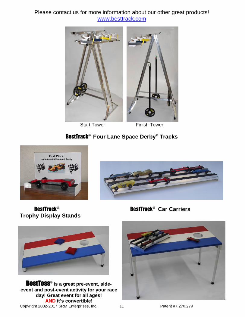
Please contact us for more information about our other great products! www.besttrack.com
Start Tower Finish Tower
BestTrack ® Four Lane Space Derby® Tracks
BestTrack ® BestTrack
® Car Carriers
Trophy Display Stands
BestToss® is a great pre-event, side-
event and post-event activity for your race day! Great event for all ages!
AND it’s convertible!

Copyright 2002-2017 SRM Enterprises, Inc. Patent #7,270,279 12
The Champ
Timer
Designed especially for your
BestTrack ® Pinewood Derby® Track.
Standard Dual Display - See who wins the race from either end of the track!
Elapsed time & placement shown on front - placement shown on back side. Large (2 ¼ inch) displays are readable across a large room. Use with or without a computer connection. Computer interface is standard.
The DragMaster® Light Tree Patent Pending
The DragMaster® Light Tree is free-standing, measures 32 inches tall, with 8 inch wide cross arms featuring LED lights, and has a 10 inch wide base plate.
You can use the DragMaster® Light Tree with a manual release start gate or a remote start gate.
The pairing of our patented Convertible Split Start Gate with the DragMaster® Light Tree creates a great drag racing event!
It even red-lights a false start!
BestTrack®
by SRM Enterprises, Inc. P.O. Box 53, Forest City, IA 50436
Phone: 641-585-2299
Updated 1/1/17


![Pinewood Derby Display Case - FINAL[1] - Cub Scoutscubscouts.org/.../uploads/2017/08/Pinewood-Derby-Display-Case.pdf · Pinewood Derby Display Case ... found it difficult to find](https://img.pdfslide.net/doc/110x75/5a9f82af7f8b9a62178cd2b9/pinewood-derby-display-case-final1-cub-derby-display-case-found-it-difficult.jpg)