Embed Size (px)
Citation preview
IMPORTANT OWNER-OPERATOR INSTALLATION INSTRUCTIONS E1521 E1536 E1524 E1542 E1528 E1548 E1532 E1560
APPLICATION FITS TORKLIFT SUPERHITCH

SUPERTRUSS EXTENSION PARTS LIST
1 - UPPER RECEIVER TUBE WITH SHANK 1 - COMPRESSION TUBE 2 - U-COLLARS (1 SUPPLIED WITH 21” & 24” EXTENSIONS) 4 - SHIM PLATES (2 SUPPLIED WITH 21” & 24” EXTENSIONS) 4 - 1/2” X 4” HEX BOLTS (2 SUPPLIED WITH 21” & 24” EXTENSIONS) 16 - 1/2” FLAT WASHERS (8 SUPPLIED WITH 21” & 24” EXTENSIONS) 4 - 1/2” LOCK NUTS (2 SUPPLIED WITH 21” & 24” EXTENSIONS) 2 - 1/4” X 1” BOLT 2 - 1/4” NUT 2 - 1/4” LOCKWASHERS 1 - PLUG BRACKET 2 - 5/16” CHAINS FROM 7” TO 31-1/2”(18cm-80cm) 2 - 1/2” EYE TO EYE TURNBUCKLES 6 - 3/8” BOW SHACKLES 2 - 5/16” SELF TAPPING SCREW * ”USED FOR WIRE HARNESS AND PLUG BRACKET”
ADDENDUM Modification to the spare tire hanger bracket may be necessary in installation of
SuperHitch
USE OF THIS PRODUCT WITHOUT A LOAD EQUALIZING SYSTEM LIMITS YOUR CAPACITY TO DEAD WEIGHT (WEIGHT CARRYING) CAPACITY. FAILURE TO STAY WITHIN LIMITATIONS WILL RESULT IN DAMAGE AND VOID YOUR WARRANTY!!!!
The TorkLift SuperTruss Extension CANNOT be used with any other type of hitch receiver. Any attempt to modify or recreate a SuperHitch receiver will result in loss of warranty. Modification of another factory or aftermarket hitch receiver in an attempt to use a TorkLift SuperTruss Extension can result in death or damage. The SuperHitch receiver, made by TorkLift is specifically designed to work with this extension, and the capacities stated for the extension are solely with the use of a TorkLift SuperHitch. Please call if you have any questions on installs or otherwise.

INSTALLATION INSTRUCTIONS 1. SEPARATE ALL FASTENERS TOFAMILIARIZE YOURSELF WITH ALL COMPONENTS. NOTE: THE CHAIN ASSEMBLIES ARE INSIDE THE UPPER TUBE OF THE EXTENSION ALL OTHER FASTENERS ARE LOCATED INSIDE THE FASTENER BOX.
NOTE: 21” & 24” EXTENSIONS REQUIRE ONLY 1 COLLAR ASSEMBLY
2. INSTALL UPPER RECEIVER TUBE W/SOLID SHANK INTO THE UPPER RECEIVER OF THE SUPERHITCH. ALSO INSTALL THE LOWER COMPRESSION TUBE INTO THE LOWER RECEIVER OF THE SUPER HITCH. INSTALL USING THE PIN AND CLIP SUPPLIED WITH THE SUPER HITCH RECEIVER.
3. PLACE BOTH COLLARS ONTO THE EXTENSION.USING ONE 1/2” X 4” BOLT WITH TWO 1/2” FLAT WASHERS, INSERT THE SHIM PLATE BETWEEN THE COLLAR AND THE EXTENSION AND INSERT THE BOLT. IT IS ALSO NECESSARY TO INSTALL THE SHIM PLATE ON THE OTHER SIDE OF THE EXTENSION AT THIS TIME. INSTALL THE LOWER BOLT THROUGH THE COLLAR, TWO1/2” FLAT WASHERS, AND SHIM PLATES. INSTALL TWO 1/2” WASHERS AND 1/2” LOCK NUTS TO THREADED END OF BOLTS. LEAVE LOOSE AT THIS TIME.

INSTALLATION INSTRUCTIONS (CONT.) 4. MAKE SURE AND PLACE ONE COLLAR INTHE MIDDLE OF THE EXTENSION AND THE OTHER AT THE END AWAY FROM THE TRUCK. TIGHTEN ALL 1/2” FASTENERS TO 60 FT. LBS. NOW REMOVE PINS TO ENSURE THE EXTENSION WILL COME OUT. IT MAY BE NECESSARY TO LOOSEN THEN RETIGHTEN THE FASTENERS TO REMOVE THE EXTENSION EASILY. NOTE: 21” & 24” EXTENSIONS ONLY REQUIRE 1 COLLAR AT THE END AWAY FROM THE TRUCK
5. INSTALL THE PLUG BRACKET ( IFNEEDED ) USING THE 1/4” HARDWARE SUPPLIED. INSTALL BELOW OR ABOVE THE CHAIN PLATE.
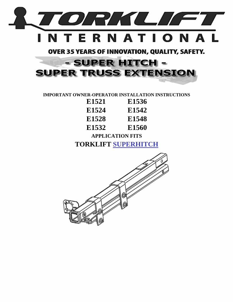
6. ASSEMBLE THE LATERALSUPPORT SAFTEY CHAINS AS
SHOWN.
TO SUPER HITCH RECEIVER
TO END OF SUPERTRUSS EXTENSION
INSTALLATION INSTRUCTIONS (CONT.) 7. TIGHTEN TURNBUCKLES BY HAND.
TIGHTEN ALL JAM NUTS AND REMAINING RIGGING WITH A WRENCH. FAILURE TO
USE THESE SAFETY CHAINS MAY RESULT IN DAMAGE OR DEATH, AND WILL VOID
YOUR WARRANTY.
SEE THE FOLLOWING PAGE FOR WEIGHT CAPACITIES AND LENGTHS.
NEVER USE THIS PRODUCT WITH ANYTHING OTHER THAN A TORKLIFT SUPERHITCH RECEIVER.
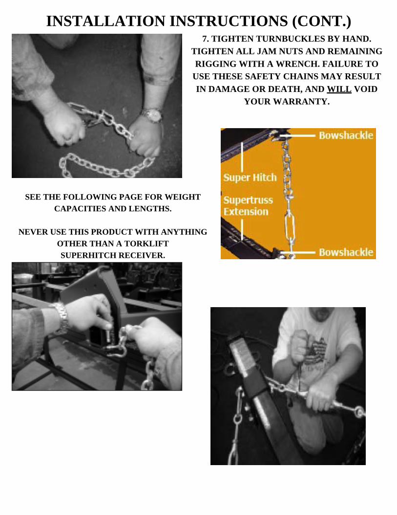
SUPERTRUSS EXTENSION WEIGHT CAPACITIES (SUPERTRUSS SOLD SEPARATELY)
ASSEMBLE THE CHAIN, BOW SHACKLES, & TURNBUCKLES AS SHOWN. TIGHTEN BOW SHACKLES AND TURNBUCKLE JAM NUTS WITH HAND TOOLS (TIGHTEN TURNBUCKLES BY HAND
DO NOT USE TOOLS TO TENSION TURNBUCKLES)
WARNING -‐ READ CAREFULLY Dead Weight (weight carrying) Weight Distributing (load equalizing)
Extension Length Tongue Weight Pull Weight Tongue Weight Pull Weight 60” (152cm) 500 lb.(226kg) 5,000 lb.(2267kg) 1,000 lb.(453kg) 10,000 lb.(4535kg) 48”(122cm) 600 lb.(272kg) 6,000 lb.(2721kg) 1,200 lb.(544kg) 12,000 lb.(5443kg) 42”(107cm) 600 lb.(272kg) 6,000 lb.(2721kg) 1,200 lb.(544kg) 12,000 lb.(5443kg) 36”(91cm) 650 lb.(294kg) 6,500 lb.(2948kg) 1,200 lb.(544kg) 12,000 lb.(5443kg) 32”(81cm) 650 lb.(294kg) 6,500 lb.(2948kg) 1,200 lb.(544kg) 12,000 lb.(5443kg) 28”(71cm) 750 lb.(340kg) 7,500 lb.(3401kg) 1,200 lb.(544kg) 12,000 lb.(5443kg) 24”(61cm) 750 lb.(340kg) 7,500 lb.(3401kg) 1,400 lb.(635kg) 14,000 lb.(6350kg) 21”(53cm) 750 lb.(340kg) 7,500 lb.(3401kg) 1,400 lb.(635kg) 14,000 lb.(6350kg)
THE USE OF THIS PRODUCT WITHOUT A LOAD EQUALIZING SYSTEM LIMITS YOUR CAPACITY TO THE DEAD WEIGHT (WEIGHT CARRYING) CAPACITY. FAILURE TO STAY WITHIN THESE
LIMITATIONS WILL RESULT IN DAMAGE AND VOID YOUR WARRANTY!!!! The Torklift SuperTruss Extension cannot be used with any other type of trailer hitch receiver. Any attempt to modify or recreate a SuperHitch receiver will result in a loss of warranty. The modification of another factory or aftermarket trailer hitch receiver in an attempt to use a Torklift SuperTruss extension can result in death or damage. The SuperHitch receiver made by Torklift is a special extra heavy-duty trailer hitch receiver, and the capacities stated for the SuperTruss extension are solely with the use of a Torklift SuperHitch.
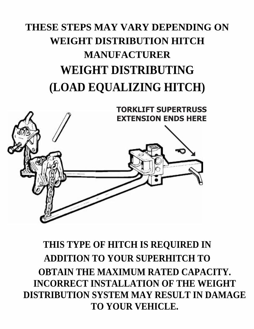
THESE STEPS MAY VARY DEPENDING ON WEIGHT DISTRIBUTION HITCH
MANUFACTURER WEIGHT DISTRIBUTING
(LOAD EQUALIZING HITCH)
THIS TYPE OF HITCH IS REQUIRED IN ADDITION TO YOUR SUPERHITCH TO
OBTAIN THE MAXIMUM RATED CAPACITY. INCORRECT INSTALLATION OF THE WEIGHT
DISTRIBUTION SYSTEM MAY RESULT IN DAMAGE TO YOUR VEHICLE.
TORKLIFT SUPERTRUSS EXTENSION ENDS HERE
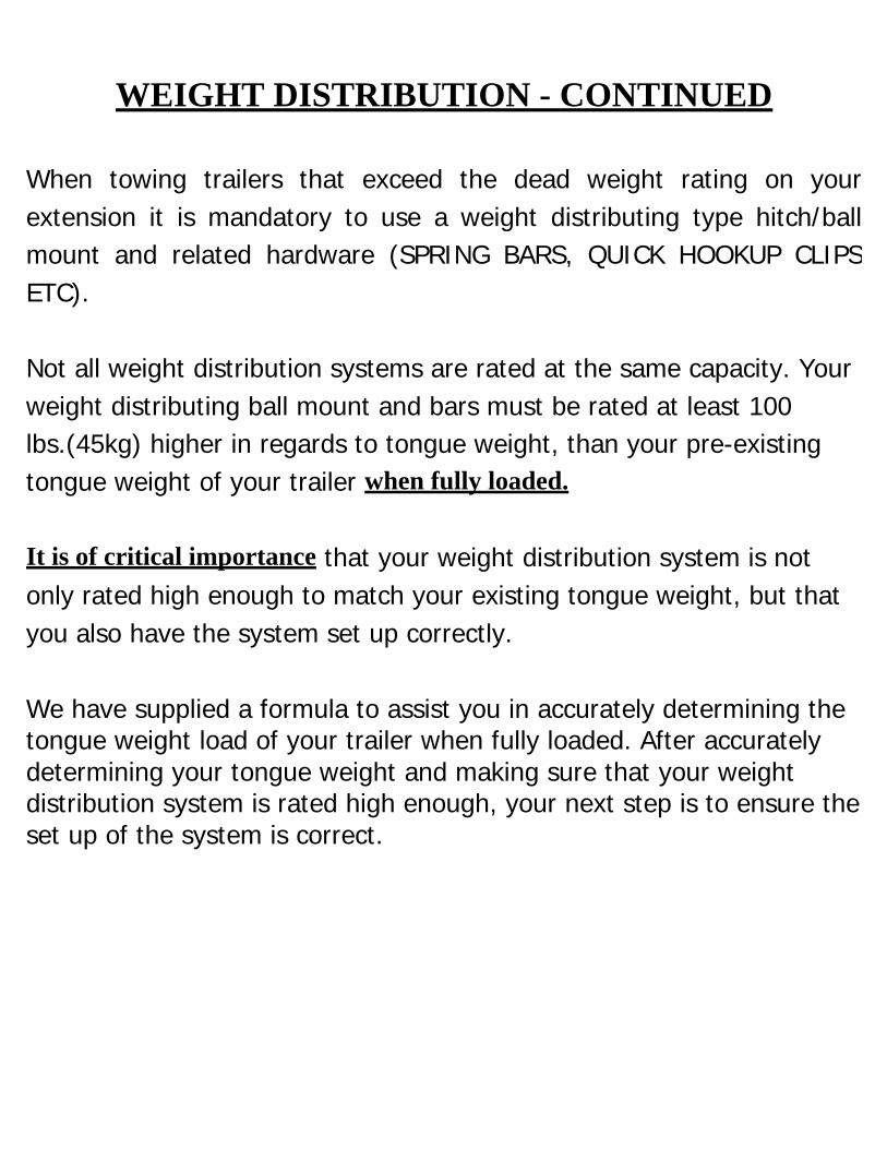
WEIGHT DISTRIBUTION - CONTINUED
When towing trailers that exceed the dead weight rating on your extension it is mandatory to use a weight distributing type hitch/ball mount and related hardware (SPRING BARS, QUICK HOOKUP CLIPS ETC).
Not all weight distribution systems are rated at the same capacity. Your weight distributing ball mount and bars must be rated at least 100 lbs.(45kg) higher in regards to tongue weight, than your pre-existing tongue weight of your trailer when fully loaded.
It is of critical importance that your weight distribution system is not only rated high enough to match your existing tongue weight, but that you also have the system set up correctly.
We have supplied a formula to assist you in accurately determining the tongue weight load of your trailer when fully loaded. After accurately determining your tongue weight and making sure that your weight distribution system is rated high enough, your next step is to ensure the set up of the system is correct.
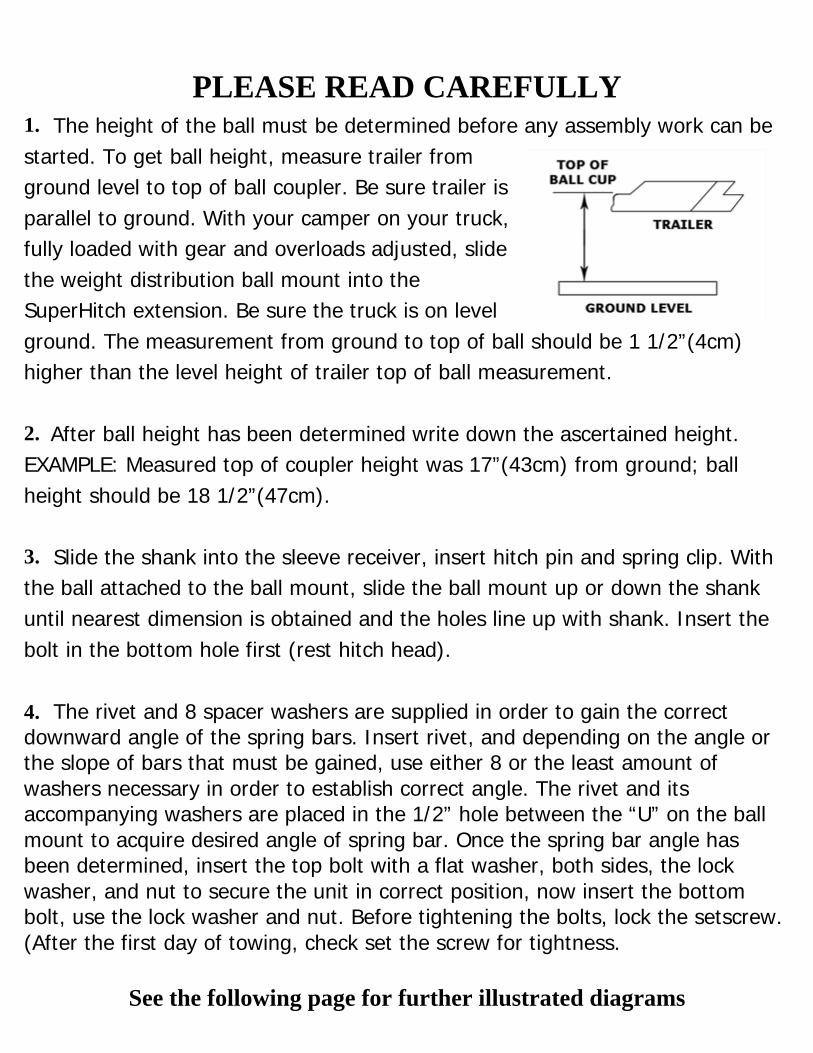
PLEASE READ CAREFULLY1. The height of the ball must be determined before any assembly work can bestarted. To get ball height, measure trailer from ground level to top of ball coupler. Be sure trailer is parallel to ground. With your camper on your truck, fully loaded with gear and overloads adjusted, slide the weight distribution ball mount into the SuperHitch extension. Be sure the truck is on level ground. The measurement from ground to top of ball should be 1 1/2”(4cm) higher than the level height of trailer top of ball measurement.
2. After ball height has been determined write down the ascertained height.EXAMPLE: Measured top of coupler height was 17”(43cm) from ground; ball height should be 18 1/2”(47cm).
3. Slide the shank into the sleeve receiver, insert hitch pin and spring clip. Withthe ball attached to the ball mount, slide the ball mount up or down the shank until nearest dimension is obtained and the holes line up with shank. Insert the bolt in the bottom hole first (rest hitch head).
4. The rivet and 8 spacer washers are supplied in order to gain the correctdownward angle of the spring bars. Insert rivet, and depending on the angle or the slope of bars that must be gained, use either 8 or the least amount of washers necessary in order to establish correct angle. The rivet and its accompanying washers are placed in the 1/2” hole between the “U” on the ball mount to acquire desired angle of spring bar. Once the spring bar angle has been determined, insert the top bolt with a flat washer, both sides, the lock washer, and nut to secure the unit in correct position, now insert the bottom bolt, use the lock washer and nut. Before tightening the bolts, lock the setscrew. (After the first day of towing, check set the screw for tightness.
See the following page for further illustrated diagrams
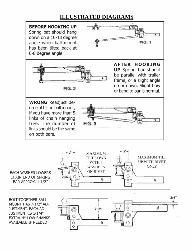
ILLUSTRATED DIAGRAMS
BEFORE HOOKING UP Spring bat should hang down on a 10-13 degree angle when ball mount has been tilted back at 6-8 degree angle.
AFTER HOOKING UP Spring bar should be parallel with trailer frame, or a slight angle up or down. Slight bow or bend to bar is normal.
WRONG Readjust de-gree of tilt on ball mount, if you have more than 5 links of chain hanging free. The number of links should be the same on both bars.
EACH WASHER LOWERS CHAIN END OF SPRING
BAR APPROX. 1-1/2”
BOLT-TOGETHER BALL MOUNT HAS 7-1/2” AD-JUSTMENT, EACH AD-JUSTMENT IS 1-1/4”EXTRA HY-LOW SHANKS AVAILABLE IF NEEDED
MAXIMUM TILT DOWN
WITH 8 WASHERS ON RIVET
MAXIMUM TILT UP WITH RIVET
ONLY
THESE STEPS MAY VARY DEPENDING ON WEIGHT DISTRIBUTION HITCH MANUFACTURER
1. Put the ball mount into the sleeve and insert the 5/8” hitch pin using spring clip to lock the pin into place,hitch balls are not furnished with the hitch as there are several sizes. Normally they are supplied or may be purchased from the dealer to match the coupler of the trailer. Ball shank bushings are supplied to reduce the size of the ball hole in the hitch down to 1”(2cm) if needed. 2. Measure the towing vehicle ball height before adding load to towing vehicle. Hook the trailer to the truck.Lock on the ball. To make hooking up easier and safer - raise front of the trailer and back of the towing vehicle above level with the trailer tongue jack. This removes some of the tension by reducing the distance between the spring bar and hook-up arm.
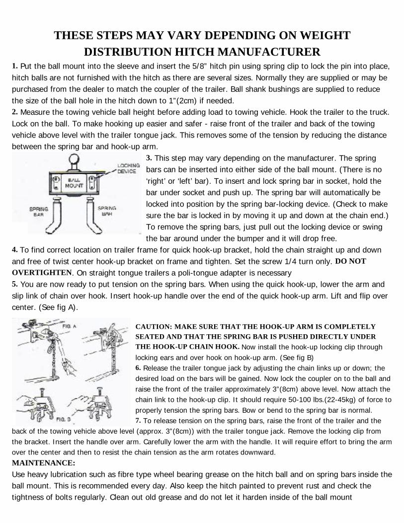
3. This step may vary depending on the manufacturer. The springbars can be inserted into either side of the ball mount. (There is no ‘right’ or ‘left’ bar). To insert and lock spring bar in socket, hold the bar under socket and push up. The spring bar will automatically be locked into position by the spring bar-locking device. (Check to make sure the bar is locked in by moving it up and down at the chain end.) To remove the spring bars, just pull out the locking device or swing the bar around under the bumper and it will drop free.
4. To find correct location on trailer frame for quick hook-up bracket, hold the chain straight up and downand free of twist center hook-up bracket on frame and tighten. Set the screw 1/4 turn only. DO NOT OVERTIGHTEN. On straight tongue trailers a poli-tongue adapter is necessary 5. You are now ready to put tension on the spring bars. When using the quick hook-up, lower the arm andslip link of chain over hook. Insert hook-up handle over the end of the quick hook-up arm. Lift and flip over center. (See fig A).
CAUTION: MAKE SURE THAT THE HOOK-UP ARM IS COMPLETELY SEATED AND THAT THE SPRING BAR IS PUSHED DIRECTLY UNDER THE HOOK-UP CHAIN HOOK. Now install the hook-up locking clip through locking ears and over hook on hook-up arm. (See fig B) 6. Release the trailer tongue jack by adjusting the chain links up or down; thedesired load on the bars will be gained. Now lock the coupler on to the ball and raise the front of the trailer approximately 3”(8cm) above level. Now attach the chain link to the hook-up clip. It should require 50-100 lbs.(22-45kg) of force to properly tension the spring bars. Bow or bend to the spring bar is normal. 7. To release tension on the spring bars, raise the front of the trailer and the
back of the towing vehicle above level (approx. 3”(8cm)) with the trailer tongue jack. Remove the locking clip from the bracket. Insert the handle over arm. Carefully lower the arm with the handle. It will require effort to bring the arm over the center and then to resist the chain tension as the arm rotates downward. MAINTENANCE: Use heavy lubrication such as fibre type wheel bearing grease on the hitch ball and on spring bars inside the ball mount. This is recommended every day. Also keep the hitch painted to prevent rust and check the tightness of bolts regularly. Clean out old grease and do not let it harden inside of the ball mount
IMPORTANT CONSUMER INFORMATION ON TOWING
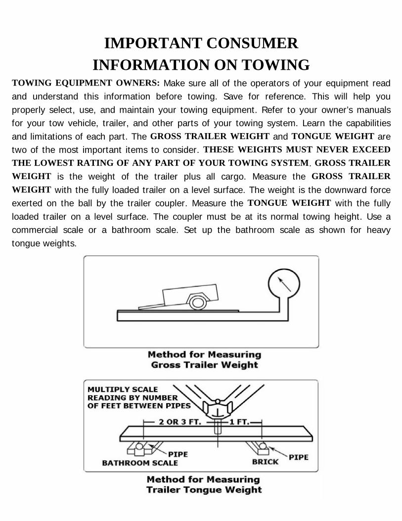
TOWING EQUIPMENT OWNERS: Make sure all of the operators of your equipment read and understand this information before towing. Save for reference. This will help you properly select, use, and maintain your towing equipment. Refer to your owner’s manuals for your tow vehicle, trailer, and other parts of your towing system. Learn the capabilities and limitations of each part. The GROSS TRAILER WEIGHT and TONGUE WEIGHT are two of the most important items to consider. THESE WEIGHTS MUST NEVER EXCEED THE LOWEST RATING OF ANY PART OF YOUR TOWING SYSTEM. GROSS TRAILER WEIGHT is the weight of the trailer plus all cargo. Measure the GROSS TRAILER WEIGHT with the fully loaded trailer on a level surface. The weight is the downward force exerted on the ball by the trailer coupler. Measure the TONGUE WEIGHT with the fully loaded trailer on a level surface. The coupler must be at its normal towing height. Use a commercial scale or a bathroom scale. Set up the bathroom scale as shown for heavy tongue weights.
YOUR TOWING EQUIPMENT HITCH BALLS Select by gross trailer weight rating, mounting platform thickness, hole size and coupler socket size. Platform must be at least 3/8 inch thick. Hole must not exceed threaded shank diameter by more than 1/16 inch. Use lock washer. Tighten per instructions. When tightened, shank must protrude beyond bottom of nut. Gross trailer weight rating and ball diameter are marked on Hitch balls. TRAILER COUPLERS The coupler socket should be smooth, clean and lightly lubricated. Tighten or adjust per coupler manufacturer’s instructions. SAFETY CHAINS Connect safety chains properly EVERY TIME YOU TOW. Cross chains under coupler. Attach securely to the hitch or tow vehicle so they can’t bounce loose. Leave only enough slack to permit full turning. Too much slack may prevent chains from maintaining control if other connections separate. Don’t let chains drag on the road. TRAILER LIGHTS, TURN SIGNALS, ELECTRIC BRAKES AND BREAK AWAY SWITCH CONNECTIONS Make these safety-critical connections EVERY TIME YOU TOW, no matter how short the trip. Check operation, including electric brake manual control, before getting on the road. SWAY CONTROLS Sway controls can lessen the effects of sudden maneuvers, wind gusts and buffeting caused by other vehicles. We recommend them for trailers with large surface areas, such as travel trailers. Adjustable friction models can help control trailers with low tongue weight percentage. OTHER USEFUL EQUIPMENT AIR SPRINGS, AIR SHOCKS or HELPER SPRINGS are useful for some hitch applications. A TRANSMISSION COOLER may be necessary for heavy towing. Many states require TOWING MIRRORS on both sides. TIRE INFLATION Check often. Follow tow vehicle and trailer manufacturer’s recommendations. Improper tire inflation can cause trailer sway.
NO PASSENGERS IN TRAILERS: NEVER allow people in trailers while towing, under any circumstances.
HELPFUL TOWING HINTS TRAILER LOADING Proper loading helps prevent sway. Place heavy object on the floor ahead of the axle. Balance the load side-to-side. Secure it to prevent shifting. Tongue weight should be 10-15 percent of gross weight for most trailers. Too low a percentage of tongue weight can cause sway. NEVER load the trailer rear heavy. LOAD THE TRAILER HEAVIER IN FRONT DRIVING The additional weight of a trailer affects acceleration, braking, and handling. Allow extra time for passing, stopping, and changing lanes. Severe bumps can damage your towing vehicle, hitch, and trailer. Drive slowly on rough roads. STOP AND MAKE A THOROUGH INSPECTION IF ANY PART OF YOUR TOWING SYSTEM STRIKES THE ROAD. CORRECT ANY PROBLEMS BEFORE RESUMING TRAVEL.CHECK FOR EXCESSIVE SWAY AND ELIMINATE IT Excessive sway can lead to loss of control. Sway motion should settle out quickly. Sway tends to increase on a downgrade. Starting slowly, increase speed in gradual steps. If sway occurs, adjust your trailer load and equipment. Repeat until the trailer is stable at highway speed. Do this whenever your trailer loading changes. IF TRAILER SUDDENLY STARTS TO SWAY Turbulence from another vehicle, a wind gust, or a downgrade can cause sudden sway. So can a shift of the trailer’s load or a trailer tire blowout. IF THE TRAILER SWAYS, IT IS THE DRIVER’S RESPONSIBILITY TO ASSESS THE SITUATION AND TAKE APPROPRIATE ACTION. Below are suggestions that may apply, depending on conditions: DO -Reduce your speed gradually -Hold the steering wheel as steady as possible -If your trailer has electric brakes, apply the brakes alone, without using the tow vehicle’s brakes.
DON’T -Don’t hit your brake pedal hard unless absolutely necessary. A “jack-knife” can result. -Don’t try to steer out of the sway condition. Sudden or violent steering can make it worse. -Don’t speed up. Sway increases as you go faster. -Don’t continue towing a trailer that tends to sway. You may lose control during an emergency maneuver or if the conditions listed above occur.
INSTRUCTIONS FOR FINISH MAINTENANCE OF TORKLIFT PRODUCTS
POWDER COATED STEEL: To keep your Torklift products looking good follow these guidelines. All steel powder coated Torklift products are sandblasted for maximum adhesion and use a high quality industrial urethane based powder coat. Due to the extreme, harsh, under car environment that your Torklift products live in, (constantly sprayed with corrosive road chemicals such as salt, and road debris), Torklift does not warranty the power coated finish.To minimize corrosion from these factors on powder coated steel products, Torklift recommends regularly cleaning and inspecting the powder-coated surface and touching up any affected areas with enamel or urethane based aerosol paint product. If there are any areas of surface rust, there are also aerosol spray rust converters available on the market that can be used as a preparation to touch-up paint application. These finish maintenance products are available at any automotive parts supplier.
POLISHED STAINLESS STEEL: Torklift utilizes quality grade 304 stainless steel in our stainless steel polished products. 304 stainless steel is well known for its anti-corrosive properties. However, in some environments such as coastal regions or when coming in contact with some road chemicals, corrosion may occur. For a quick clean simply use WD-40 and a cloth rag. We also recommend occasional polishing of our polished stainless products to maintain their attractive finish. Use an approved stainless steel chrome or aluminum mag wheel polish cleaning product, which can be purchased from any automotive parts supplier.