Embed Size (px)
Citation preview
A-150 Installation Instructions
1
1. IMPORTANT: Place furnace floor on a flat level surface. The end of the
floor without the angle is the stoker-hopper end. Position the floor with the
short angle welded to it towards the chimney this is the where the stack pipe
will come out of.
2. Stand furnace on the floor, centering it so that the angles on the face of the
furnace are inside the angels that are welded to furnace floor. Keep black
face plate of furnace even with edge of floor.
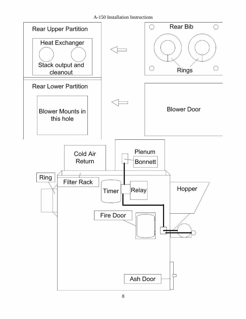
3. Install heat exchanger to furnace. Make sure that stack and cleanout outlets
are in their lowest position. Tighten nuts securely in an alternative diametric
pattern to compress the rope seal between the flanges.
4. There are two legs (angles) inside furnace. Fasten to heat exchanger; adjust
bolts on bottom of legs until bolts rest snugly on floor.
5. Install rope gasket around furnace exhaust pipe inside of mounting holes for
heat exchanger. Rope gasket is self has a self- adhesive backing on it. It is
provided in the ash tub.
6. Remove side panels from box marked sides. Using a screw driver or chisel,
pry open edge in S bend on side panel.
7. Find packet of screws inside box marked top.
8. Slide S bend of jacket panel over angle on black face plate, keeping jacket
side panel inside of floor angle. Do both sides.
9. Fasten rear bib of jacket with 1” screws provided to rear of furnace.
10. Place a light smear of furnace cement or high temperature silicone around
fire door frame. Place fire door into furnace inspection opening. Drill a hole
in top of door frame, and bottom of frame with 1/8” bit, and secure with drill
screws provided in ash tub. Attach spring handle to fire door. Bend hook of
spring hand open, then thread hook through predrilled hole in fire door
handle, then bend hook closed. Spring handle and fire door can be found in
ash tub.
A-150 Installation Instructions
2
11. Get lower partition out of top box (it is the larger silver piece with square
hole in it). Open the S cleat bend on the top end. Slide lower center partition
through blower door opening. Top of bottom partition gets threaded up
between furnace and heat exchanger. Place against protruding angles, from
side panels. Drill holes with 1/8” bit and secure with ½” screws. Top of
bottom partition gets threaded down between furnace and heat exchanger and
slid into S cleats on bottom partition don’t secure now.
12. Mount blower motor onto blower unit (as per instructions packed with
blower). Insert blower assembly into furnace, allowing ¼” to ½” of blower
unit to protrude beyond center partition. Note: Blower belt should be
somewhat loose. Making belt too tight will cause excessive and rapid wear
on the sleeve and bearings in both motor and blower. Note: blower is free
standing does not get bolted to furnace. Vibration is reduced when blower
sits on rubber pads.
13. Place jacket handle on blower door in pre-drilled hole. Slide washer onto
handle stem. Slide through blower door. Tap lock washer until tight against
inside blower door. Tighten handle latch onto handle stem with screw.
Install blower door on furnace with handle on top of door.
14. In box marked top. Remove 2 jacket rings. Slide one over each stack pipe
outlet and clean out opening.
15. Place top of jacket onto furnace with filter rack going over heat exchanger.
16. Drill several 1/8” holes along top partition and top and secure with 1” screws.
17. Drill several holes with 1/8” bit through furnace top and side panels and
secure with 1” screws.
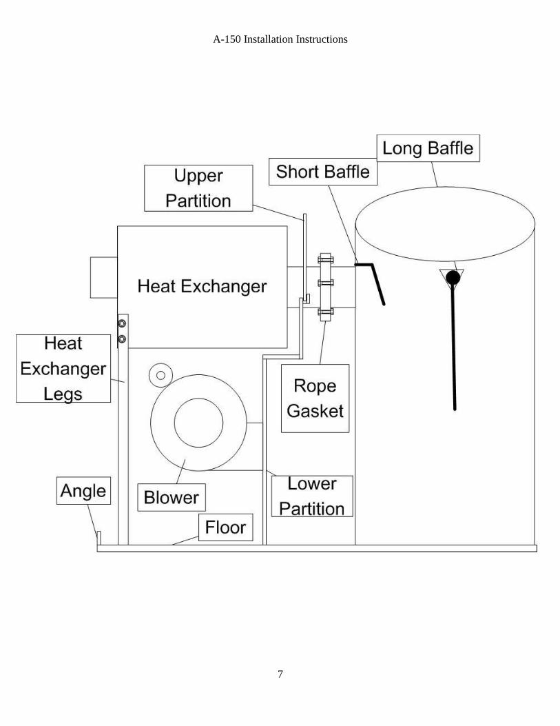
18. Reach inside stoker unit opening and place small hanging baffle above
exhaust opening inside furnace.
19. Hang long baffle onto angles welded in upper portion of furnace. Place
reinforcement angle toward heat exchanger.
20. Plenum chambers may now be installed.
A-150 Installation Instructions
3
21. Stoker units are shipped completely assembled. Lift stoker unit into opening,
bottom of stoker has a ¼” rod welded in place which must go inside stoker
opening. Place a thick smear of furnace cement on flange of stoker and tilt
into place, securing with 3/8 x 1 ¼ machine screws, washers, and nuts
provided in ash tub. Remove shipping screw from gear box lid.
22. Place hopper on stoker unit, and fasten to furnace with large metal washers
and nuts. The hopper bottom should lap over stoker throat approximately 1”.
Since the same hopper is used for several different stokers, it may be
necessary to trim the opening. Bend flange down to fit inside of throat of
stoker. Be sure feed mechanism is free to operate.
INSTALLING STACK PIPE The heat exchanger has 2 – stack outlets. Either
one may be used to connect stove pipe to chimney. The other opening must be
capped, to be used for a clean out. If stack pipe must be reduced in size, reduce
stack size at thimble. It is important to run full size stack from furnace to thimble
in chimney. Install barometric draft control in first full section of stack closest to
furnace. Follow instructions packed with draft control, making sure draft control
bearings are level and face of control is perpendicular to floor.
Install control harness. Secure timer and relay to furnace with ½” screws near the
top above the fire door.
Install fan limit control…Into Hot Air Plenum. Timer and relay may be mounted
directly to furnace jacket.
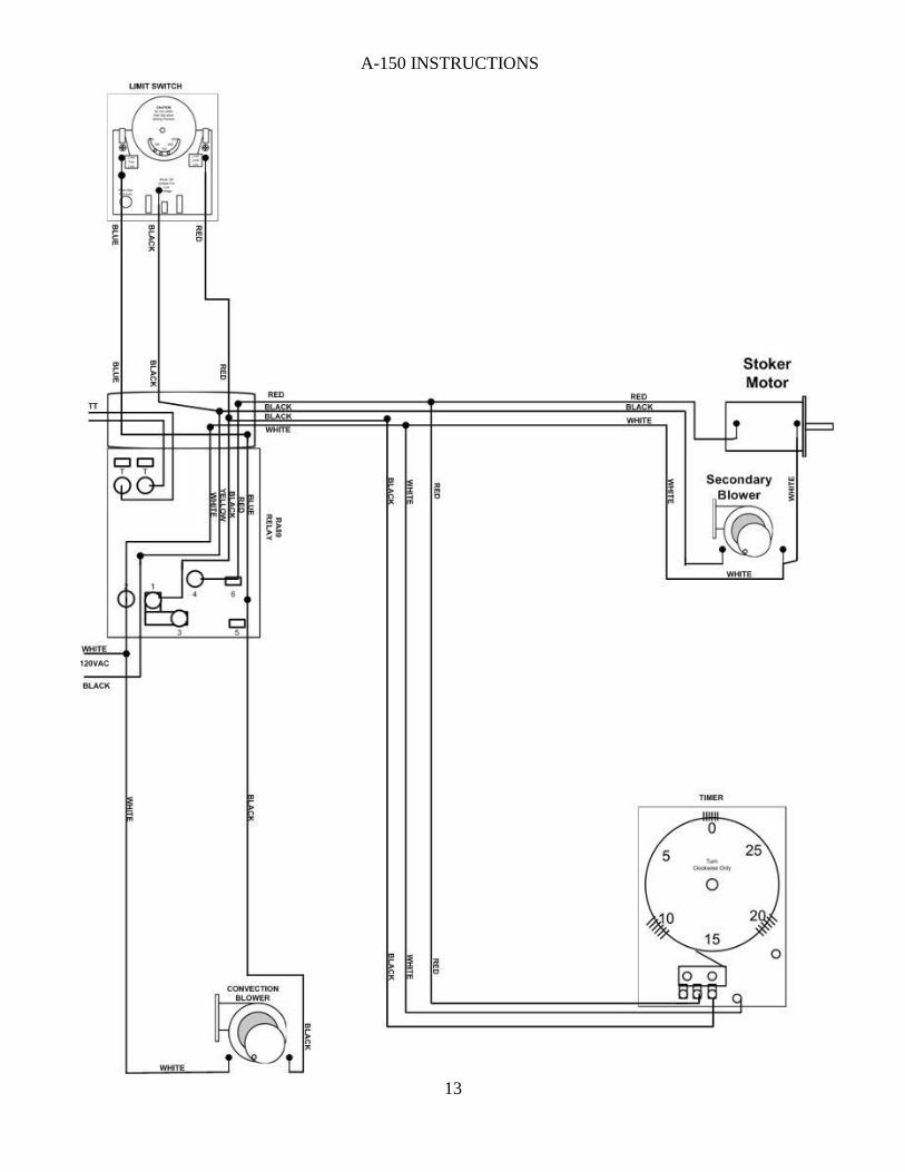
Connect 115 volt power supply to switch, black wire gets connected to open screw
on switch, white wire in switch bow. Wire furnace following wiring diagram and
any applicable UL and local codes. Wire stoker unit and convection blower (see
wiring diagram page 13)
After making electrical connections, turn blower on. Be sure blower is running
proper direction. To change blower direction, follow blower instructions on motor
or install motor on the opposite side of blower.
Locate thermostat in an area where heat from furnace can freely be reached. Mount
plastic wall plate of thermostat. Connect thermostat wires to screws on lower
portion of wall plate. Run thermostat wire to relay on furnace and connect wires to
terminals marked T. T. (note: color coding is unimportant).
A-150 Installation Instructions
4
STARTING FIRE: DO NOT USE AN ACCELLERANT SUCH AS: Gasoline,
Kerosene, Litter Fluid, Or Etc. Put dry coal in hopper, pull coal down to cover
entire grate. Crush several charcoal briquettes into smaller pieces on 1 piece of
newspaper, crumble newspaper and dig it through coal, so it touches the grate.
Light newspaper with a match, turn switch on, when charcoal turns red and starts
to spark, place a few hand full of coal on top of charcoal. If fire moves toward
bottom of grate before fire is established, coal feed can be slowed down by turning
red nut counter clockwise or by flipping feed bolt to a sideward position. (Part #22
on unit specification sheet)
AFTER STARTING FIRE Allow stove and chimney to warm up. Insert draft
gauge through predrilled hole in upper portion of green fire door. Open air shutter
(located on the bottom of scroll between gear box and stoker motor about ½”).
Then with stoker motor running and feeding coal adjust barometric draft regulator
until draft gauge reads (-.02). If draft is less than a (-.02) with the barometric draft
regulator closed you must close the air shutter (located at bottom of scroll between
gear box and stoker motor). If draft is higher than a (-.02) you must adjust the
barometric draft regulator. Move weight on barometric draft regulator left or right
to obtain the (-.02). Recheck until you obtain a
SETTING TIMER The timer is factory set. Yellow clock wheel makes one
revolution every 30 minutes. Each clip sticking out of yellow wheel will cause
stoker to run approximately 15 seconds when clip touches switch. Timer settings
will vary depending upon chimney drafts. Normal timing cycle is about one
minute on, fourteen minutes off. (4 clips side by side). Four clips at zero and four
clips at fifteen. If timing cycle needs to be increased, add one or two clips in both
groups of clips. Or if in cases of chimney having poor draft, clips may be placed in
3 groups at numbers 0- 10- 20.
COAL FEED (Red Nut)…To increase coal feed and fire size, turn red nut
clockwise (CW). To reduce coal feed and fire size, turn red nut counter clockwise
(CCW)
After a fire has been established and all fresh coal that was laying on grate has
burned, its time to set coal feed. When stoker unit is running steady
(approximately ½ hour) fire bed should extend downward to lower portion of the
grate with approximately 2” of ash on bottom of grate. When thermostat is
satisfied, stoker unit will shut off.
A-150 Installation Instructions
5
When stoker only runs during timing cycles, the fire bed will gradually shrink to
approximately 3” to 4” of red coals. After proper length of fire bed is obtained,
coal feed is set.
INITIAL COAL FEED: Advance red nut all the way forward. Then turn it
counter clockwise 11 or 12 turns if burning rice coal, if burning buckwheat coal
turn coal feed counter clockwise 9 or 10 turns. When furnace is running for about
an hour under full load grates should have about 2” of dead ash on them before
falling into ash pan.
As the price of fuel continues to increase KEYSTOKER, continues to improve
and make its products more fuel efficient. To obtain a more complete burn out of
coal, a small secondary blower motor was attached to the stoker unit. THIS
MOTOR IS DESIGNED FOR CONTINOUS RUN.
When the large stoker motor is running on demand, small blower will assist with
combustion and heat output, by producing a more intense and hotter fire. When
demand cycle is completed, large stoker motor will shut off, and small secondary
motor will continue to run. This will cause the coal that is already on the grate to
burn, rather than to allow coal to smolder and die out in an unburned condition.
This will achieve a cleaner ash, and allow more heat to be produced and absorbed
into heating system.
During summer operation, the small combustion motor will force a small amount
of air through grates at all times, which will cause the ash to become like powder.
It also prevents the fire from going out. At the same time, it reduces the size of fire
bed to approximately 1 ½” to 2” which will prevent furnace from over-heating.
Proper sizing of fire is obtained by turning red nut on feed control arm. Clockwise
(CW) for more coal feed and counter clockwise (CCW) for less coal feed.
Location and final adjustment for red nut will be determined by size of coal you
purchase. For rice coal, red nut might be turned down 12 turns for maximum
settings, whereas for buckwheat coal, red nut might only be turned down 10 turns
from maximum settings.
During winter operation, hot coals should never be pushed off the end of grate.
This indicated that coal feed needs to be reduced (CCW) or if during winter
operation: fire bed is too small, turn red nut (CW).
A-150 Installation Instructions
6
After coal feed adjustment is completed, if during summer, the convection blower
runs when thermostat is not calling for heat DO NOT ADJUST COAL FEED,
REDUCE TIMER ONLY. If fire goes out DO NOT ADJUST COAL FEED.
Increase timer only.
CLEANING AND SERVICING It is important to clean and lubricate furnace
when shutting down at the end of heating season. Corrosion of heating equipment
is greatly reduced by not allowing soot to remain in furnace during summer
months.
Remove and clean stack pipe, clean base of chimney. Examine chimney for
blockage with a mirror. Brush off barometric damper. Clean tubes and area
around tubes in heat exchanger, including entrance into chamber of furnace.
Remove clean out plate (see unit specifications) from stoker unit by removing 2
screws and vacuuming out fly ash from under grate annually.
Oil stoker motor and blower motors with SAE 20 non detergent motor oil. Oil
gear box with #90 Gear Oil – Oil level should not be less than ½ full and no more
than ¾ full.
Remove al local from hopper; -remove hopper-place a few drops of oil on all
moving parts, joints, and bearings to prevent freeze up.
Replace air filters.
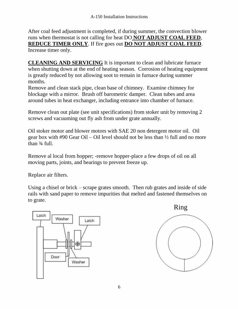
Using a chisel or brick – scrape grates smooth. Then rub grates and inside of side
rails with sand paper to remove impurities that melted and fastened themselves on
to grate.
Ring
A-150 Installation Instructions
7
A-150 Installation Instructions
8
A-150 Installation Instructions
9
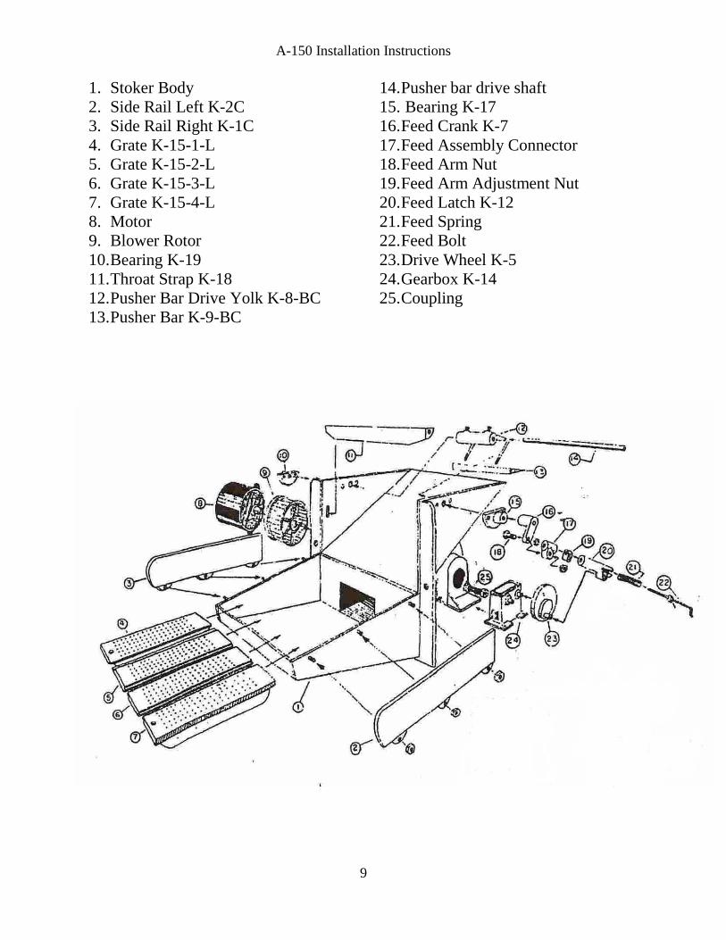
1. Stoker Body
2. Side Rail Left K-2C
3. Side Rail Right K-1C
4. Grate K-15-1-L
5. Grate K-15-2-L
6. Grate K-15-3-L
7. Grate K-15-4-L
8. Motor
9. Blower Rotor
10. Bearing K-19
11. Throat Strap K-18
12. Pusher Bar Drive Yolk K-8-BC
13. Pusher Bar K-9-BC
14. Pusher bar drive shaft
15. Bearing K-17
16. Feed Crank K-7
17. Feed Assembly Connector
18. Feed Arm Nut
19. Feed Arm Adjustment Nut
20. Feed Latch K-12
21. Feed Spring
22. Feed Bolt
23. Drive Wheel K-5
24. Gearbox K-14
25. Coupling
A-150 INSTRUCTIONS
10
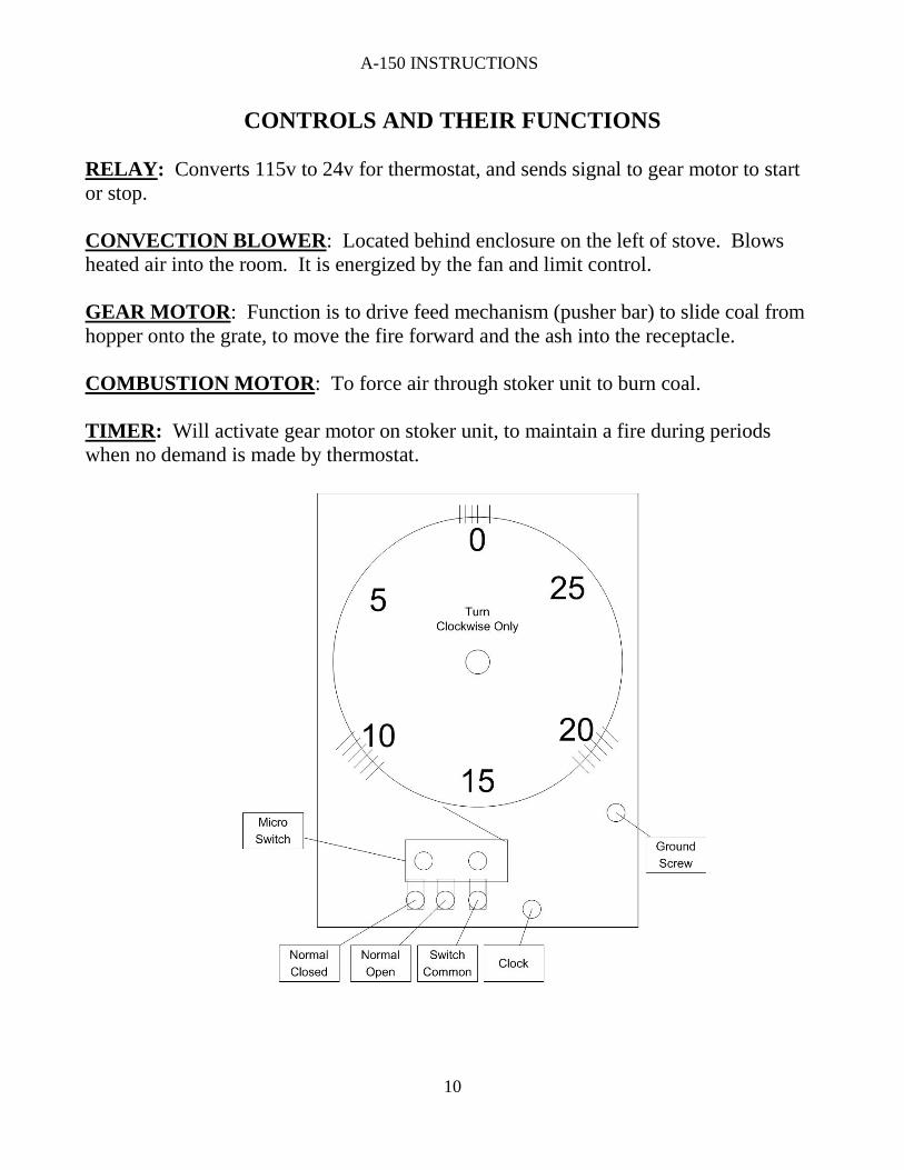
CONTROLS AND THEIR FUNCTIONS
RELAY: Converts 115v to 24v for thermostat, and sends signal to gear motor to start
or stop.
CONVECTION BLOWER: Located behind enclosure on the left of stove. Blows
heated air into the room. It is energized by the fan and limit control.
GEAR MOTOR: Function is to drive feed mechanism (pusher bar) to slide coal from
hopper onto the grate, to move the fire forward and the ash into the receptacle.
COMBUSTION MOTOR: To force air through stoker unit to burn coal.
TIMER: Will activate gear motor on stoker unit, to maintain a fire during periods
when no demand is made by thermostat.
A-150 INSTRUCTIONS
11
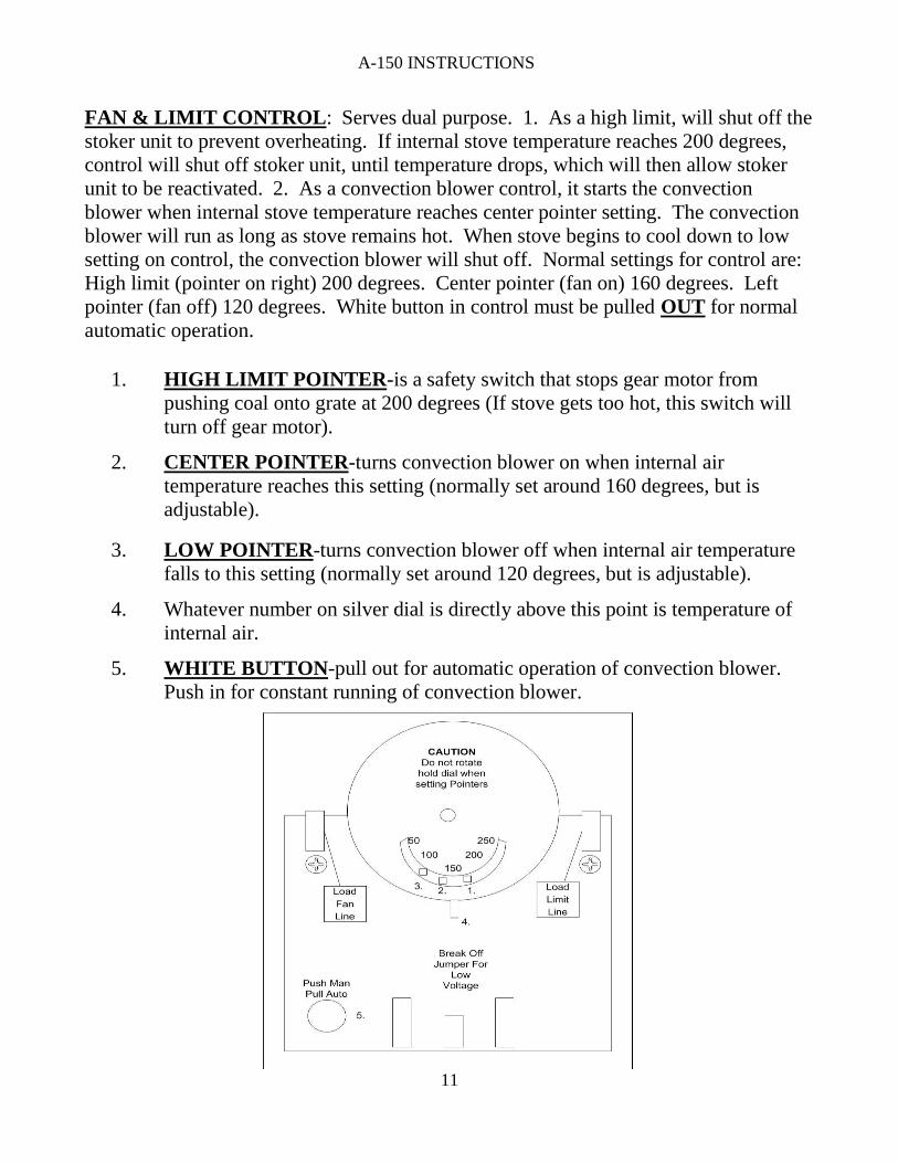
FAN & LIMIT CONTROL: Serves dual purpose. 1. As a high limit, will shut off the
stoker unit to prevent overheating. If internal stove temperature reaches 200 degrees,
control will shut off stoker unit, until temperature drops, which will then allow stoker
unit to be reactivated. 2. As a convection blower control, it starts the convection
blower when internal stove temperature reaches center pointer setting. The convection
blower will run as long as stove remains hot. When stove begins to cool down to low
setting on control, the convection blower will shut off. Normal settings for control are:
High limit (pointer on right) 200 degrees. Center pointer (fan on) 160 degrees. Left
pointer (fan off) 120 degrees. White button in control must be pulled OUT for normal
automatic operation.
1. HIGH LIMIT POINTER-is a safety switch that stops gear motor from
pushing coal onto grate at 200 degrees (If stove gets too hot, this switch will
turn off gear motor).
2. CENTER POINTER-turns convection blower on when internal air
temperature reaches this setting (normally set around 160 degrees, but is
adjustable).
3. LOW POINTER-turns convection blower off when internal air temperature
falls to this setting (normally set around 120 degrees, but is adjustable).
4. Whatever number on silver dial is directly above this point is temperature of
internal air.
5. WHITE BUTTON-pull out for automatic operation of convection blower.
Push in for constant running of convection blower.
A-150 INSTRUCTIONS
12
CONVECTION BLOWER-when running, it will take cool air from room, and force it
through heated air chamber inside stove, and return heated air into room. Blower can
only be activated by Fan Limit Switch.
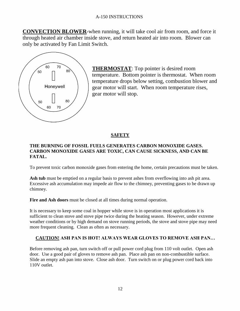
THERMOSTAT: Top pointer is desired room
temperature. Bottom pointer is thermostat. When room
temperature drops below setting, combustion blower and
gear motor will start. When room temperature rises,
gear motor will stop.
SAFETY
THE BURNING OF FOSSIL FUELS GENERATES CARBON MONOXIDE GASES.
CARBON MONOXIDE GASES ARE TOXIC, CAN CAUSE SICKNESS, AND CAN BE
FATAL.
To prevent toxic carbon monoxide gases from entering the home, certain precautions must be taken.
Ash tub must be emptied on a regular basis to prevent ashes from overflowing into ash pit area.
Excessive ash accumulation may impede air flow to the chimney, preventing gases to be drawn up
chimney.
Fire and Ash doors must be closed at all times during normal operation.
It is necessary to keep some coal in hopper while stove is in operation most applications it is
sufficient to clean stove and stove pipe twice during the heating season. However, under extreme
weather conditions or by high demand on stove running periods, the stove and stove pipe may need
more frequent cleaning. Clean as often as necessary.
CAUTION! ASH PAN IS HOT! ALWAYS WEAR GLOVES TO REMOVE ASH PAN…
Before removing ash pan, turn switch off or pull power cord plug from 110 volt outlet. Open ash
door. Use a good pair of gloves to remove ash pan. Place ash pan on non-combustible surface.
Slide an empty ash pan into stove. Close ash door. Turn switch on or plug power cord back into
110V outlet.
A-150 INSTRUCTIONS
13
A-150 INSTRUCTIONS
14
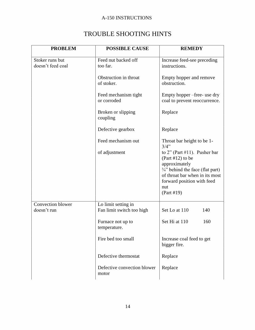
TROUBLE SHOOTING HINTS
PROBLEM POSSIBLE CAUSE REMEDY
Stoker runs but
doesn’t feed coal
Feed nut backed off
too far.
Increase feed-see preceding
instructions.
Obstruction in throat Empty hopper and remove
of stoker. obstruction.
Feed mechanism tight Empty hopper –free- use dry
or corroded coal to prevent reoccurrence.
Broken or slipping Replace
coupling
Defective gearbox Replace
Feed mechanism out Throat bar height to be 1-
3/4”
of adjustment to 2” (Part #11). Pusher bar
(Part #12) to be
approximately
¾” behind the face (flat part)
of throat bar when in its most
forward position with feed
nut
(Part #19)
Convection blower Lo limit setting in
doesn’t run Fan limit switch too high Set Lo at 110 140
Furnace not up to Set Hi at 110 160
temperature.
Fire bed too small Increase coal feed to get
bigger fire.
Defective thermostat Replace
Defective convection blower
motor
Replace
A-150 INSTRUCTIONS
15
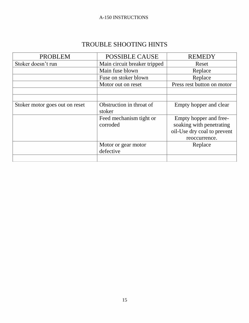
TROUBLE SHOOTING HINTS
PROBLEM POSSIBLE CAUSE REMEDY Stoker doesn’t run Main circuit breaker tripped Reset
Main fuse blown Replace
Fuse on stoker blown Replace
Motor out on reset Press rest button on motor
Stoker motor goes out on reset Obstruction in throat of
stoker
Empty hopper and clear
Feed mechanism tight or
corroded
Empty hopper and free-
soaking with penetrating
oil-Use dry coal to prevent
reoccurrence.
Motor or gear motor
defective
Replace
A-150 INSTRUCTIONS
16
A-150 Warranty Keystone Manufacturing Company extends the following warranties to the original owner from the
date of purchase.
Five Years Workmanship on stove body
Two years on grates and side rails
One year all electric controls and motors.
Warranty does not apply if damage occurs because of improper handling, operation, abuse, rust,
corrosion, misuse or use beyond rated capacity.
This warranty does not apply if the product has been altered in any way after leaving the factory.
All warranty claims should be made through dealer where the appliance was originally purchased.
Model, Stoker Unit Number 1 ½ x 3 tag (found below hopper) and original copy of the sales receipt
need be presented to dealer.
If a consumer chooses to make a warranty claim directly through Keystone Manufacturing Company
model, stoker unit number, and copy of the original sales receipt are required. Customer must provide
a credit card which will be charged for the full retail price for the product plus shipping and handling.
When defective part is returned to the company and found to be a defect within warranty period the
consumer’s credit card will be credited back the cost of part.
Keystone Manufacturing Company assumes no responsibility for any labor expanses, for service,
product removal, reinstallation or any freight charges for parts returned to the company.
If defective in material or workmanship and if removed by the owner with in warranty period Keystone
manufacturing will at their opinion repair or replace the product.
This warranty is limited to defective parts, repair, or replacement at our opinion and excludes any
incidental and consequential damages connected there with.
Warranty exclusions, labor, door gasket, ash tub, hopper and paint
Furnace Information
Dealer_________________________________________
Date of purchase_________________________________
Stoker unit number_______________________________
Stove Model____________________________________
A-150 INSTRUCTIONS
17
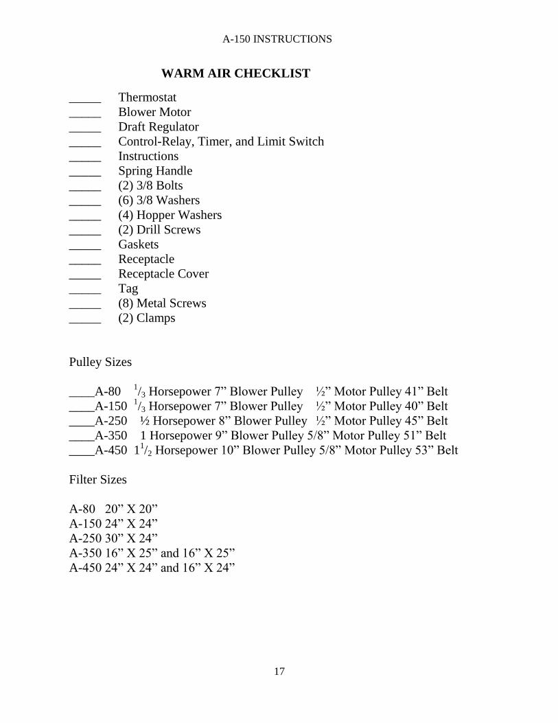
WARM AIR CHECKLIST
_____ Thermostat
_____ Blower Motor
_____ Draft Regulator
_____ Control-Relay, Timer, and Limit Switch
_____ Instructions
_____ Spring Handle
_____ (2) 3/8 Bolts
_____ (6) 3/8 Washers
_____ (4) Hopper Washers
_____ (2) Drill Screws
_____ Gaskets
_____ Receptacle
_____ Receptacle Cover
_____ Tag
_____ (8) Metal Screws
_____ (2) Clamps
Pulley Sizes
____A-80 1/3 Horsepower 7” Blower Pulley ½” Motor Pulley 41” Belt
____A-150 1/3 Horsepower 7” Blower Pulley ½” Motor Pulley 40” Belt
____A-250 ½ Horsepower 8” Blower Pulley ½” Motor Pulley 45” Belt
____A-350 1 Horsepower 9” Blower Pulley 5/8” Motor Pulley 51” Belt
____A-450 11/2 Horsepower 10” Blower Pulley 5/8” Motor Pulley 53” Belt
Filter Sizes
A-80 20” X 20”
A-150 24” X 24”
A-250 30” X 24”
A-350 16” X 25” and 16” X 25”
A-450 24” X 24” and 16” X 24”


![Untitled-1 [] · 3 bedroom flat no. e.0204 zn0 floor, tower e. superarea (approx) windsor court. gh osa. sector uttar pradesh ano constructionthereon furure flat no. 1504, 15th floor](https://img.pdfslide.net/doc/110x75/60048c78f4f4c608d67a0aef/untitled-1-3-bedroom-flat-no-e0204-zn0-floor-tower-e-superarea-approx.jpg)