Embed Size (px)
Citation preview
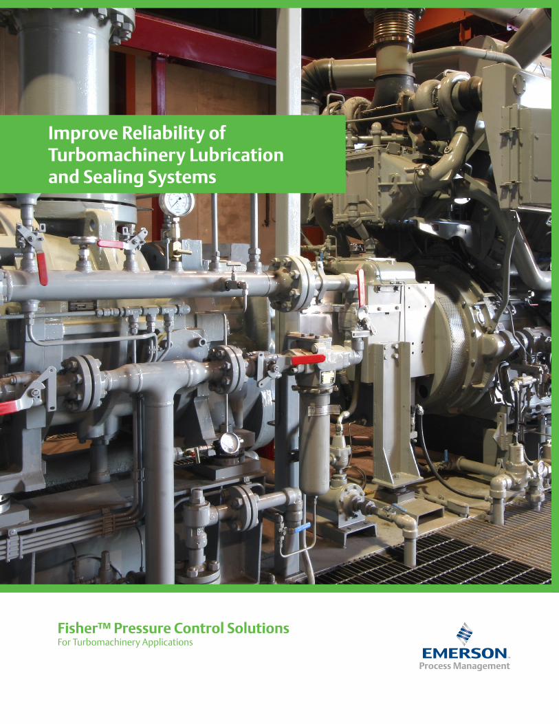
Improve Reliability of Turbomachinery Lubrication and Sealing Systems
For Turbomachinery ApplicationsFisher™ Pressure Control Solutions
Turbomachinery lubrication and sealing systems play an integral role in keeping your plant up and running. Robust pressure control is required for reliable operation of these systems. Therefore, selecting the right pressure control solution is critical. Typical pressure control challenges are: • Speed of response of the pressure control devices • Incorrect sizing and selection of pressure control solutions • Unstable operation of the pressure control devicesThese challenges could result in unplanned shutdowns, increased maintenance costs and personnel health and safety issues.
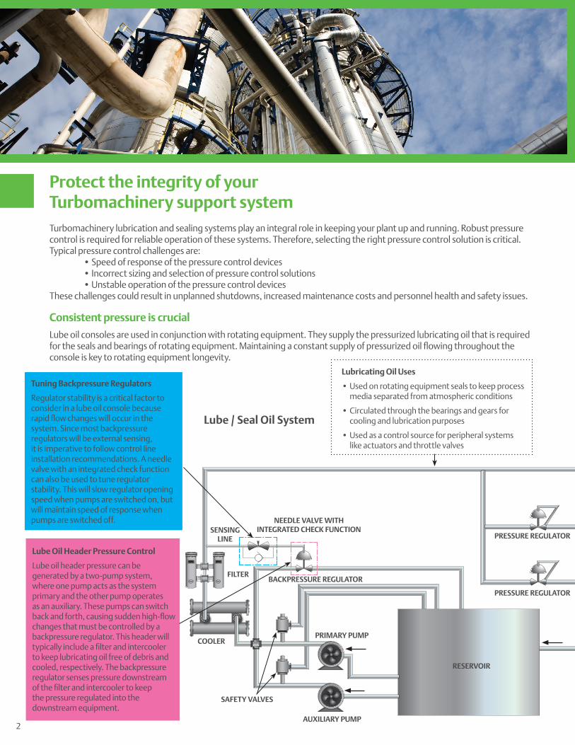
Consistent pressure is crucial
Lube oil consoles are used in conjunction with rotating equipment. They supply the pressurized lubricating oil that is required for the seals and bearings of rotating equipment. Maintaining a constant supply of pressurized oil flowing throughout the console is key to rotating equipment longevity.
Protect the integrity of your Turbomachinery support system
RESERVOIR
Lube / Seal Oil System
BACKPRESSURE REGULATOR
PRESSURE REGULATOR
PRESSURE REGULATOR
AUXILIARY PUMP
SAFETY VALVES
SENSING LINE
NEEDLE VALVE WITH INTEGRATED CHECK FUNCTION
COOLER
FILTER
PRIMARY PUMP
Tuning Backpressure Regulators
Regulator stability is a critical factor to consider in a lube oil console because rapid flow changes will occur in the system. Since most backpressure regulators will be external sensing, it is imperative to follow control line installation recommendations. A needle valve with an integrated check function can also be used to tune regulator stability. This will slow regulator opening speed when pumps are switched on, but will maintain speed of response when pumps are switched off.
Lube Oil Header Pressure Control
Lube oil header pressure can be generated by a two-pump system, where one pump acts as the system primary and the other pump operates as an auxiliary. These pumps can switch back and forth, causing sudden high-flow changes that must be controlled by a backpressure regulator. This header will typically include a filter and intercooler to keep lubricating oil free of debris and cooled, respectively. The backpressure regulator senses pressure downstream of the filter and intercooler to keep the pressure regulated into the downstream equipment.
Lubricating Oil Uses
• Used on rotating equipment seals to keep process media separated from atmospheric conditions
• Circulated through the bearings and gears for cooling and lubrication purposes
• Used as a control source for peripheral systems like actuators and throttle valves
2
Emerson™ offers a broad portfolio of turbomachinery pressure control solutions that address these challenges and minimize the associated impacts. Fisher™ direct operated regulators provide the fast speed of response and precise control required for reliable operation of small, medium or large lube/seal oil systems. Our solutions are easy to size and maintain and they meet the API 614 standard for lube/seal oil systems.
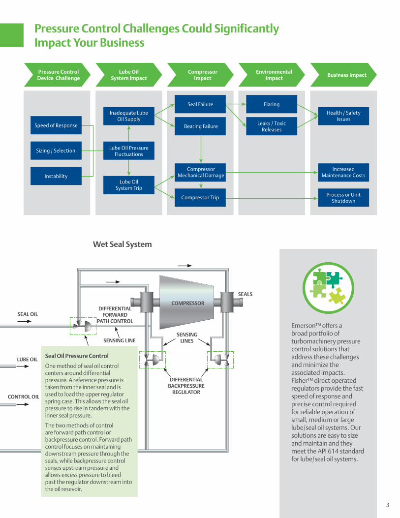
Pressure Control Device Challenge
Speed of Response
Health / Safety Issues
Sizing / Selection Lube Oil Pressure Fluctuations
Bearing Failure
Increased Maintenance Costs
Process or Unit Shutdown
Instability
Lube Oil System Impact
Compressor Impact
Environmental Impact
Business Impact
Inadequate Lube Oil Supply
Lube Oil System Trip
Seal Failure Flaring
Leaks / Toxic Releases
Compressor Mechanical Damage
Compressor Trip
Pressure Control Challenges Could Significantly Impact Your Business
COMPRESSOR
Wet Seal System
DIFFERENTIAL BACKPRESSURE
REGULATOR
DIFFERENTIAL FORWARD
PATH CONTROL
PRESSURE REGULATOR
CONTROL OIL
LUBE OIL
SEAL OIL
SEALS
PRESSURE REGULATOR
SENSING LINESSENSING LINE
Seal Oil Pressure Control
One method of seal oil control centers around differential pressure. A reference pressure is taken from the inner seal and is used to load the upper regulator spring case. This allows the seal oil pressure to rise in tandem with the inner seal pressure.
The two methods of control are forward path control or backpressure control. Forward path control focuses on maintaining downstream pressure through the seals, while backpressure control senses upstream pressure and allows excess pressure to bleed past the regulator downstream into the oil resevoir.
3
Innovative high pressure solutions for harsh environments
Dry gas seal systems typically require regulators that can withstand high loading pressures. Emerson™ offers solutions that were specifically designed to meet these high pressure requirements. Process gas can often contain sour gas contaminants, leading to valve wear and unplanned shutdowns. Emerson’s portfolio includes NACE compatible materials which extend regulator service life in sour gas environments.
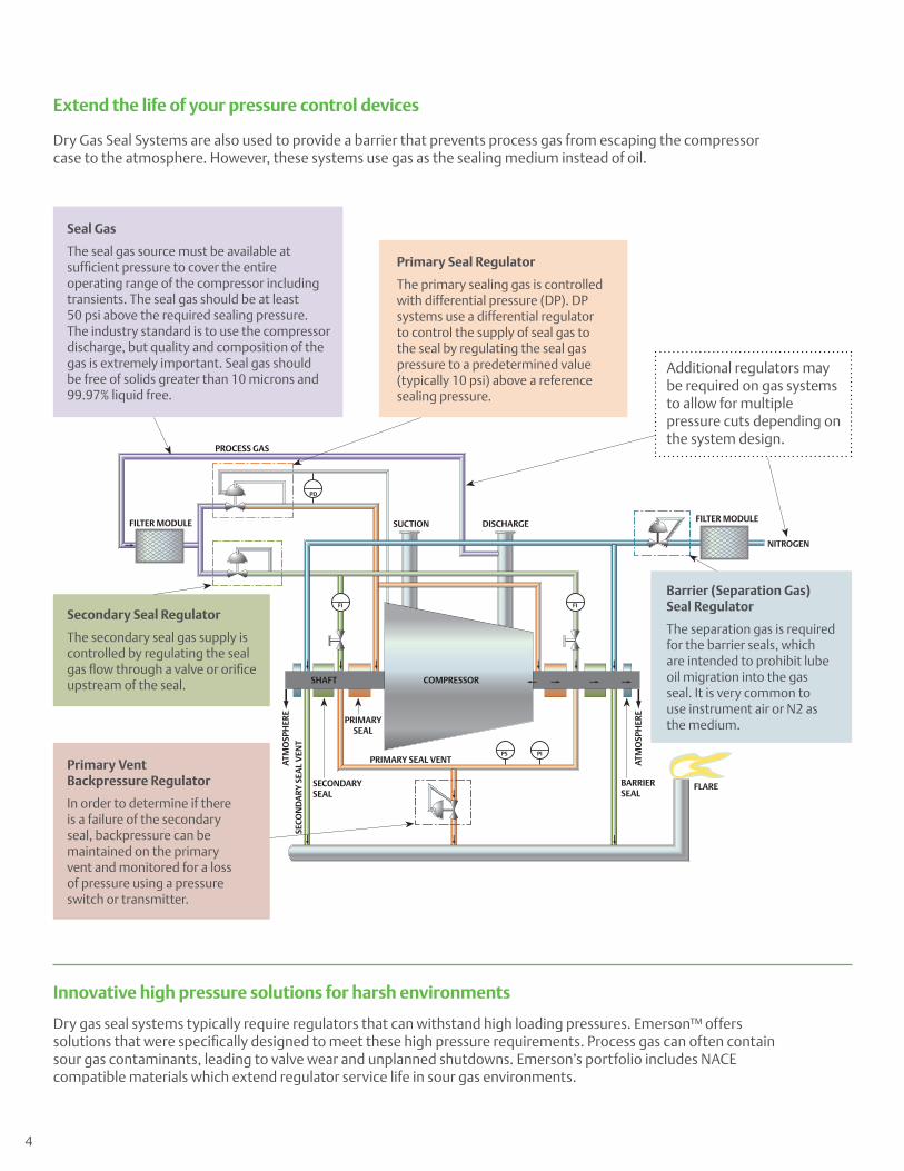
Dry Gas Seal Systems are also used to provide a barrier that prevents process gas from escaping the compressor case to the atmosphere. However, these systems use gas as the sealing medium instead of oil.
Seal Gas
The seal gas source must be available at sufficient pressure to cover the entire operating range of the compressor including transients. The seal gas should be at least 50 psi above the required sealing pressure. The industry standard is to use the compressor discharge, but quality and composition of the gas is extremely important. Seal gas should be free of solids greater than 10 microns and 99.97% liquid free.
Primary Seal Regulator
The primary sealing gas is controlled with differential pressure (DP). DP systems use a differential regulator to control the supply of seal gas to the seal by regulating the seal gas pressure to a predetermined value (typically 10 psi) above a reference sealing pressure.
Secondary Seal Regulator
The secondary seal gas supply is controlled by regulating the seal gas flow through a valve or orifice upstream of the seal.
Primary Vent Backpressure Regulator
In order to determine if there is a failure of the secondary seal, backpressure can be maintained on the primary vent and monitored for a loss of pressure using a pressure switch or transmitter.
Barrier (Separation Gas) Seal Regulator
The separation gas is required for the barrier seals, which are intended to prohibit lube oil migration into the gas seal. It is very common to use instrument air or N2 as the medium.
Additional regulators may be required on gas systems to allow for multiple pressure cuts depending on the system design.
PROCESS GAS
FILTER MODULEFILTER MODULE SUCTION DISCHARGE
COMPRESSOR
PRIMARY SEAL VENT
PRIMARYSEAL
SECONDARY SEAL
BARRIERSEAL
FLARE
SECO
ND
ARY
SEA
L V
ENT
ATM
OSP
HER
E
ATM
OSP
HER
E
SHAFT
PD
FI FI
PS PI
NITROGEN
Extend the life of your pressure control devices
4
Expert help when you need it the most
Emerson state-of-the art flow and materials labs provide an extensive worldwide network of engineers, application experts and sales professionals to help you size, select and troubleshoot your pressure regulators. Emerson test and evaluation teams provide flow, material and environmental testing under real-world operating conditions before you place them in your application.
Training to help you effectively maintain your systems
No other regulator manufacturer in the world offers more products and local services dedicated to safe, effective applications than Emerson. We strive to be the leader in training pressure control personnel.
Emerson offers a wide array of onsite and offsite training for all levels of your organization. Together with our local business partners we work with you to develop training that fits the needs of your team, whether it is application training for engineers, operational training for operators or maintenance training for technicians. With our courses, your personnel can learn to:
• Perform maintenance on regulators and relief valves
• Troubleshoot field problems
• Understand the influence of the service environment on regulator performance
• Properly size regulators and relief valves
Global Support and Service
Emerson has more than 2000 technical experts in nearly 200 offices; application support is just a call or click away.
Minimize unscheduled downtime by increasing your knowledge
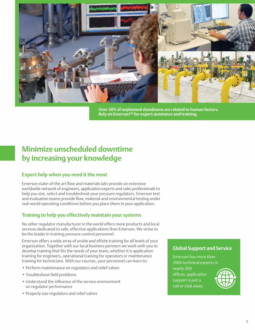
Over 50% of unplanned shutdowns are related to human factors. Rely on Emerson™ for expert assistance and training.
5
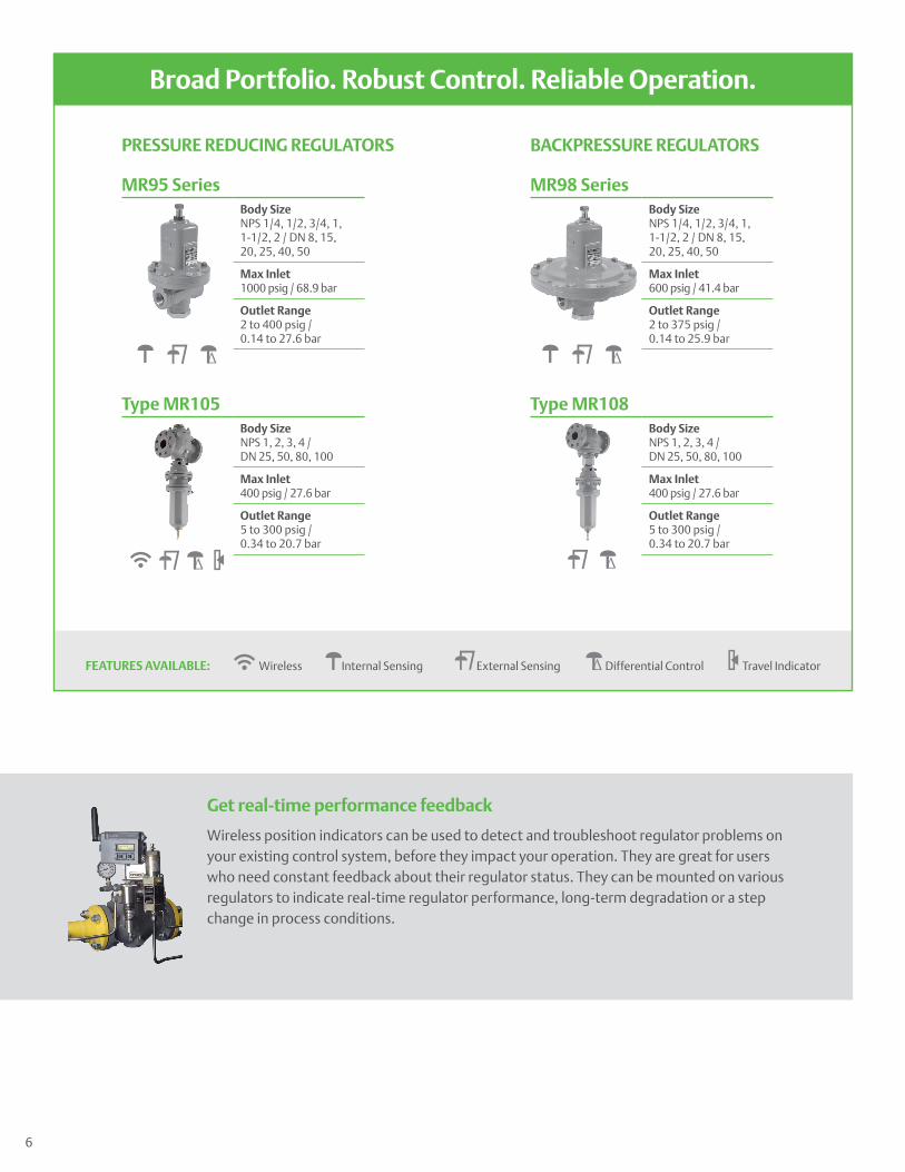
FEATURES AVAILABLE: Wireless Internal Sensing External Sensing Δ Differential Control Travel Indicator
Broad Portfolio. Robust Control. Reliable Operation.
MR95 SeriesBody SizeNPS 1/4, 1/2, 3/4, 1, 1-1/2, 2 / DN 8, 15,20, 25, 40, 50
Max Inlet1000 psig / 68.9 bar
Outlet Range2 to 400 psig /0.14 to 27.6 bar
MR98 SeriesBody SizeNPS 1/4, 1/2, 3/4, 1, 1-1/2, 2 / DN 8, 15,20, 25, 40, 50
Max Inlet600 psig / 41.4 bar
Outlet Range2 to 375 psig /0.14 to 25.9 bar
PRESSURE REDUCING REGULATORS BACKPRESSURE REGULATORS
Type MR105Body SizeNPS 1, 2, 3, 4 / DN 25, 50, 80, 100
Max Inlet400 psig / 27.6 bar
Outlet Range5 to 300 psig /0.34 to 20.7 bar
Type MR108Body SizeNPS 1, 2, 3, 4 / DN 25, 50, 80, 100
Max Inlet400 psig / 27.6 bar
Outlet Range5 to 300 psig /0.34 to 20.7 bar
Get real-time performance feedback
Wireless position indicators can be used to detect and troubleshoot regulator problems on your existing control system, before they impact your operation. They are great for users who need constant feedback about their regulator status. They can be mounted on various regulators to indicate real-time regulator performance, long-term degradation or a step change in process conditions.
Δ Δ
ΔΔ
6
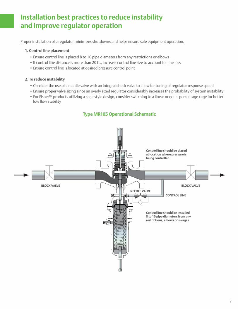
Installation best practices to reduce instability and improve regulator operation
Proper installation of a regulator minimizes shutdowns and helps ensure safe equipment operation.
1. Control line placement
• Ensure control line is placed 8 to 10 pipe diameters from any restrictions or elbows • If control line distance is more than 20 ft., increase control line size to account for line loss • Ensure control line is located at desired pressure control point
2. To reduce instability
• Consider the use of a needle valve with an integral check valve to allow for tuning of regulator response speed • Ensure proper valve sizing since an overly sized regulator considerably increases the probability of system instability • For Fisher™ products utilizing a cage style design, consider switching to a linear or equal percentage cage for better
low flow stability
Control line should be installed 8 to 10 pipe diameters from any restrictions, elbows or swages.
Control line should be placed at location where pressure is being controlled.
BLOCK VALVE BLOCK VALVE
NEEDLE VALVECONTROL LINE
7
Type MR105 Operational Schematic
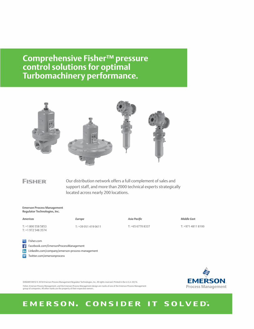
Comprehensive Fisher™ pressure control solutions for optimal Turbomachinery performance.
Fisher.com
Facebook.com/EmersonProcessManagement
Twitter.com/emersonprocess
LinkedIn.com/company/emerson-process-management
Emerson Process Management Regulator Technologies, Inc.
Americas
T: +1 800 558 5853T: +1 972 548 3574
Europe
T: +39 051 419 0611
Asia Pacific
T: +65 6770 8337
Our distribution network offers a full complement of sales and support staff, and more than 2000 technical experts strategically located across nearly 200 locations.
D352451X012 © 2016 Emerson Process Management Regulator Technologies, Inc. All rights reserved. Printed in the U.S.A. 04/16.
Fisher, Emerson Process Management, and the Emerson Process Management design are marks of one of the Emerson Process Management group of companies. All other marks are the property of their respective owners.
Middle East
T: +971 4811 8100