Embed Size (px)
Citation preview

I , �
IMPROVED ATTENUATED PROBE ELECTRONICS
Clint Sprott
March 29, 1965
PLP 48
Copy No. J\J
University of Wisconsin
Thermonuclear
Plasma Studies

IMPROVED ATTENUATED PROBE ELECTRONICS
Introduction
Clint Sprott
March 2 9, 1965
PLP 43 described a differential amplifier for use with
attenuated probes. The amplifier discussed there had the
following disadvantages:
(1) Driving the shields of the probe leads permits low
impedance plasma to capacitively couple to the shield through
the glas s , producing an erroneous reading of the floating
potential.
(2) The common mode rejection ratio was strongly dependent
on frequency; and although it was possible to obtain a CMRR of
100:1 at any given frequency up to about 1 mc., the CMRR was much
worse at other frequencies, particularly abo�e 2 mc.
(3) The rise time of the amplifier was 0.2 �sec., corres
ponding to a high frequency cutoff of only 2 mc.
(4) The circuit was unnecessarily complicated. In particular,
the nuvistors, which were originally used to give a high input
impedance, are no longer necessary when the amplifier is used
with an attenuated probe since, in that case, we desire a low
input impedance.
(5) The filament battery lifetime was short and the ampli
fier gain was quite dependent on battery voltage.
This paper d�scribes the steps which have been taken to over
come the above difficulties and suggests several improvements
which might yet be made.

- 2 -
Coupling between Plasma and Shield
Whenever a shield is driven by a cathode follower, it ceases
to be effective as a shield if its impedance to ground (usually
the cathode resistance) is comparable to the coupling impedance
between the plasma and the shield. Figure 1 shows an equivalent
circuit for the plasma coupling. Vp is the floating potential,
a rapidly changing function of time. Rp is the plasma impedance,
which is purely resistive at low frequencies, and strongly depend
ent on plasma density. Cp is the coupling capacitance between the
plasma at the surface of the glass and the shield inside. By
direct calculation (concentric cylinders) , an upper limit of
50 pf can be placed on Cpo Th.is is in agreement with the value
obtained by measuring the capacitance between the shield and a
layer of aluminum foil wrapped around the glass. It is easily
shown that for effective shielding, the following relationship
must hold:
» Rk .
Consider some typical values:
Rp = 10K = 10<fJ'L
W = 2iTf = 101 cps
Cp = 10 pf = 10 ... /1 f
Then = 14K. With the 12K cathode resistor
previously used, the shielding would not be effective. To
eliminate this problem, the shields were disconnected from the
cathodes and grounded. The penalty for grounding them is that
a higher attenuation factor is necessary, reducing the sensitivity
of the system. With the shields grounded, the capacitive pickup
was at most one part in 10� at all frequencies.

-3-
Common Mode Rejection Ratio
For a differential amplifier whose input consists of two
identical cathode followers, the common mode rejection ratio
critically depends upon accurately balancing both the gain and
phase shift of the cathode followers for the following reasons:
(1) Any difference in gain or phase shift causes part of
the common mode signal to appear at the output.
(2 ) The feedback and thus the capacitance between the
center conductor and shields will differ and the attenuator
will no longer be balanced.
Although it was possible to compensate for these effects
at a given frequency, it was virtually impossible to obtain a
high common mode rejection ratio over a large frequency spectrum
with that amplifier.
Grounding the shields eliminates the second difficulty,
since the capacitance at the output of the attenuator is a
constant, dependent only on the cable capacitance and the input\
capacitance of the amplifier.
To overcome the other difficulty, a single-ended transistor
amplifier was used. Since the whole circuit "floats" with the
floating potential, there is no necessity of matching gains.
The only requirement is that the capacitance and resistance from
each input to ground must be equal, a condition which is easily
satisfied with capacitive trimmers and pots.
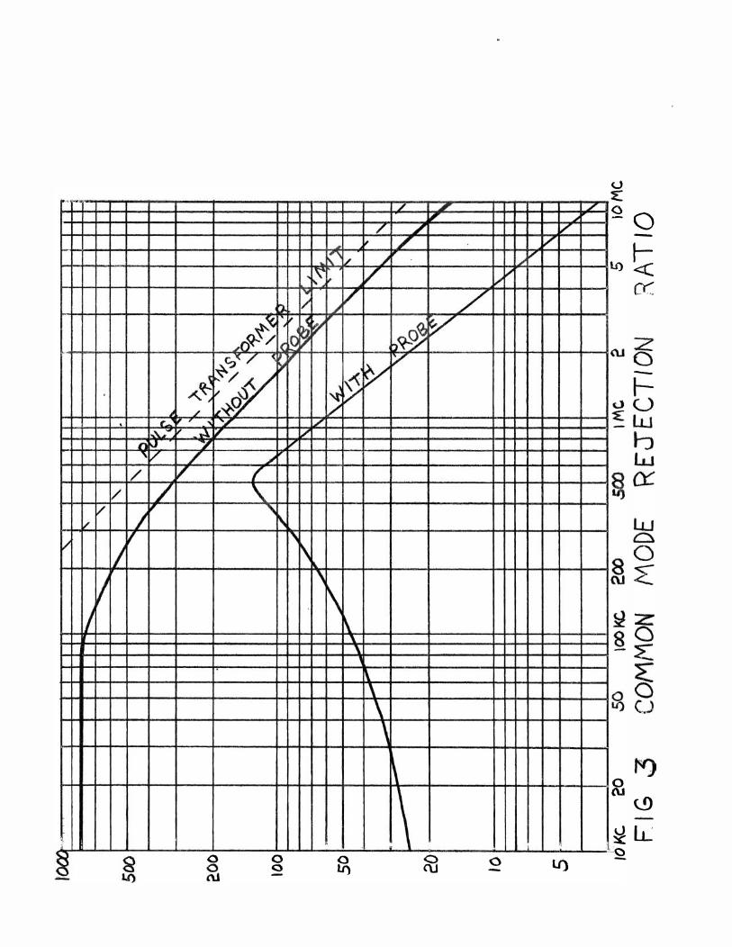
Figure 3 shows the common mode rejection ratio as a function
of frequency for a typical probe-amplifier combination. The
amplifier can be adjusted so that the resonance can be moved to
any frequency below about 1 mc. The limitations on the CMRR
with the new system are twofold:

-4-
(1) The attenuators in the probe are not ideal. This
effect will be discussed at so�e length in the next section.
(2) At high frequencies the CMRR is limited by the capaci
tive coupling between windings in the output pulse transformer.
Figure 2 shows an equivalent circuit for this effect. By direct
calculation, the CMRR of the pulse transformer is given by
CMRR = I 1
Using the manufacturer's specification of C� = 1.23 pf,
the dotted curve in Figure 3 was obtained. This represents the
maximum CMRR that one can achieve using a PE-5l63 with a termina
tion of RL = 500.1L. (500JL was the smallest load that the
amplifier was capable of driving without reducing the frequency
response ) .

-5-
Frequency Response
The rise time of the amplifier in PLP 43 was only 0.2 �sec.
The frequency response was limited by the leakage inductance of
the output pulse transformer. In particular, the leakage induc
tance and capacitive load cause a resonance in the frequency
response, above which the signal is greatly attenuated. By
critically damping, the resonance can be el��ed, but the
high frequency cutoff is given by f = 2iTJ LLCL For a
capacitive load of 200 pf (180 for 6 ft. of RG 58 + 20 for the
scope), the cutoff frequency is 4 mc., using the manufacturer's
value of Ll = 14 �hy.
In the new amplifier, the frequency response was doubled by
using a high impedance cable (RG l14AU, 6 pf 1 ft.) to couple
the output to the scope. It was also found necessary to use a
faster transistor (2Nl132) since the cutoff frequency of the
2N404 and 2Nl304 is rather low.
Figure 4 shows the frequency respdnse of the amplifier
with the above modifications. With the probe attached, the
frequency response is reduced. The reason for the limited band
width of the probe is that the attenuators in the probe are non-ideal.
Figure 5 shows an equivalent circuit for the attenuator. The capa
citance C is � 0.2 pf, assumed distributed evenly inside the
resistor. With Ro adjusted so that the ideal attenuator relation
ship is satisfied (RC = RoCo), we would expect zero phase shift
at all frequencies if the distributed capacitance, CI, between
the resistor and ground is neglected. When one includes CI
(assumed to be distributed evenly along the resistor), the phase
shift is given by the equation
� / W 2.J1. 2. r_' 2. fJ = 1I W2. Ri. e,""i + I -

-6-
For low frequencies «(JJ<.< 2 mc.), ¢::: J taRC) j and for
high frequencies (fiJ > > 2 me.), ¢::: Pc" . In our case, it
appears that CI
is comparable to C, limiting the frequency
response to /V 2 mc.
Furthermore, any small difference in C'in the two attenuators
puts the output signals out of phase with one another and reduces
the common mode rejection ratioo

-7-
Amplifier Circuit
The necessity of a low input impedance and a relaxation of
the requirement that the shields be driven allows a much simpler
amplifier circuit to be used. A single-ended transistor amplifier
is mounted inside a box so that if "floats" with the common mode
potential. The capacitance between the + input and ground is
�10 pf and the capacitance between the - input and ground is
�50 pf ( 40pf of which is the capacitance between the pulse
transformer primary and the interwinding shield) . When the
amplifier is connected to a probe, the probe lead with greatest
capacitance to its shield should be used as the + input. The
2 -2 5 pf trimmers at the input allow the capacitances to be brought
into balance. In some cases, additional capacitance must be added
trom the + input to grou�d.
The common mode is read off the + input, through an attenuator,
with a TektronixP602 8 (Xl) probe or any other cable with capaci
tance less that �IOO pf. The attenuation when used unterminated
with a I meg. scope input is 5:1. When the amplifier is used
alone, the common mode frequency response is linear to > 10 mc.
When used with a probe, the gain falls off at high frequencies
(see Figure 7).

-8-
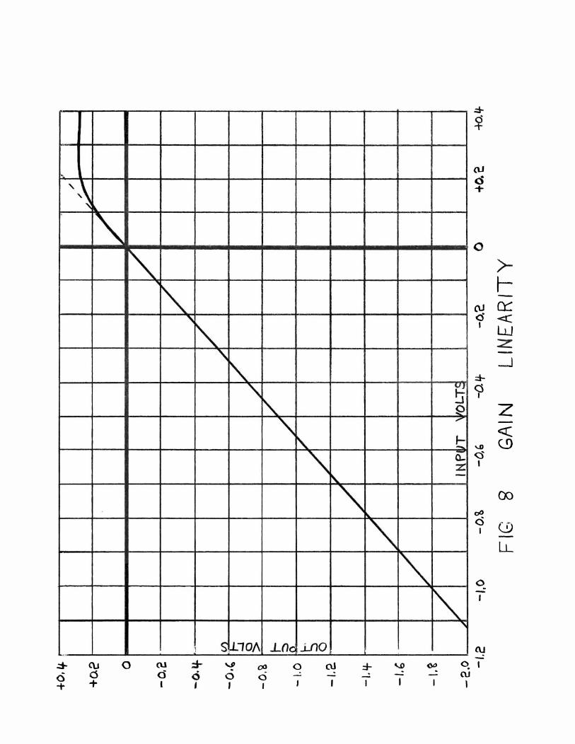
Gain Linearity
The transistor was purposely biased so as to handle signals
between -10 volts and +0.2 volts at the input in orde-r to reduce
drain on the battery. Output voltage vs. input is plotted in
Figure 8. The curve remains linear to below -10 volts. The
amplifier gain is � 2 (because of the 1: 2 ratio at the pulse
transformer) . With an attenuated probe, the overall gain of the -3
system is ,...,.,J 5 x 10 . Therefore, one would expect the system
to saturate at difference voltages of"""'" 40 volts. By rotating
the probe 1800, however, the saturation point is � 2 KV.
If one desires to extend the linear range further into
the positive region, the value of the lOOK resistor in Figure 6
should be lowered. For example, a 33K would extend the linear
range by a factor of three, while also increasing the battery
current by three.
The probe-amplifier gain for the common mode is "...., 6 x 10⁻¹.
When used with a Tektronix type L preamp., the eM sensitivity
is about 10 volts/cm. on the most sensitive scale.

-9-
Battery Voltage
Neither the amplifier gain nor the frequency response is
affected by the battery voltage. However, the signal level over
which the amplifier is linear is directly proportional to the
battery voltage.
The amplifier requires about 1 rna. at 22 volts. Using a
Mallory RM-4l2 mercury battery, rated at 1600 ma.-hours, we
would expect a lifetime of over one year, assuming four hours
of operation per day. There is reason to believe that the
battery life is even longer when used intermittently.

-10 -
Future Improvements
The limitations of the present design which one would hope
to overcome in the future are:
(1) Limited frequency response
(2) Low level signals at the output
(3) Poor CMRR at high frequencies
Three improvements immediately suggest themselves:
(1) Add a small capacitance (�l pf) in parallel with
each resistor at the end of the probe. This would make the
attenuators more nearly ideal and thus help the frequency response
and CMRR. It would also make possible a lower attenuation factor,
giving more signal at the amplifier output. This change would
necessitate an amplifier with a higher input impedance (�20K)
and a larger signal handling capacity.
(2) Use a faster pulse transformer. A PE-SlS8 has a rated
rise time of 20 nsec. (20 mc. cutoff). In addition, the inter
winding capacitance is about half that of a PE-Sl63 insuring a
higher common mode rejection ratio. By terminating the output
with a lower impedance, the CMRR could be further improved. This,
however, would require an amplifier with a lower output impedance
in order to drive the pulse transformer at low frequencies.
(3) Use a stage of amplification ahead of the emitter
follower to amplify only the difference signal. The CMRR would
be improved by a factor equal to the gain of the amplifier.
Each of these ideas are presently being studied, and it is
hoped that a probe-amplifier system can be made with a bandwidth
of at least 10 kc. - 20 mc.

PROBE i �---r-------:------,-i:'I !-.f-
'SHIELD
F\G 1 PLASMA COUPLING "TO PROBE SHIELD
I
�IG 2 CAPAC IT l VE COUPL) NG BETVJEEN
TR ANSFORMER WINDINGS
·�-' '..,
�.
1/
� j
§
.
1/ I/
�
/
, r_ ... '-i'"
ri � '/
/ / /
J II
1/
S
�
b. 1/ � , II
� iOq...�/ 10 1< C?'< / � �tI
� �� � .. :�?'J " ' -.: �
�- 7 ;/ 'l V
/ � V i
\. 'l\-
, i\
0 0 0 <:) -
/ I �
L f\' 1/ � ��\. V
� v
�
� � � � /
./
, \
� '\. \
� \ \ ,
6\
7 7 , 7
/ �V
V ......
7 b�rft V V
�
\ i 2 <) -
V /'
ll)
u � 7 i
�O -lO�
1
cc
-
2 t!)
�l.L 2.

.,
..
-
.,
-.
I -'I
o
� ./
/' / J"
7 /
I
(;) �
1\
...,. . �� .�
�
o n.i
-� 0 (t t--.J
0 t -�
\, o
•
� 'f'
, �
it
11) o
,
, I
cu
d
lI)
(\1
(.) �
8 f.O
8 (U
<.) � 0 0
0 fJ}
Lu (/) Z 0 0... cJ) W cr
>-<...) Z UJ :J 0 lU 0::: L.L
--' « -t-Z lJ...J Q:::" lU LL l1-0

r-- I G' 5 :- ! ".
EQUIVALE NT CIRCUI1" FOR A NON -I DEA L A.TIENUATOR
r-.�0 eM OUT
j:-i#, 2-25 r--I -\OO-K�JI -_
-_-"J __ _ MALLORY . '+ M R M - 4-12 + INPUT 0:' /100 -- 22 V �} . _ 1/._ ..... ..---t PE5/G3
0.1/100 10K !\\o(
,':"" \ N PUT -:::- · I f e· '-1-: ---'----'---'------; I -:" 5K�
FIG 6 DIFFERENTIAL AMPLIFIER

",
/'
-
c o Uj
� 0 � n..
l-� 0 ...L. I-s
o ru o
I �
I •
"
d �)
:L.
I� , ,
t>
If) d
J I
I V
• I
'I
C\J d
w (/)
l.t) Z o Q..
(\.1
(/) w 0::
o W � D a
(
�
o Lf) �
a u
0 ru L-
0 CJ) � o LL --
()
.:0> .:l0-a +
��\ "
"-
(\J o +
�
o
�
(U d I
"'
� '\
� '\ �
� :..J P
'\ "
r\. t: '\ 0:.
:z: r\. -"\
"\
(lJ d +
0
(\.J <:5 I
:::t-Ci I
...0 <:5
I
01' C
I
I'" 0
'j S.lLl0A v . o ,
00 o
I
L()q..i..l10 o ru -
f --
I I
'" -I
-I
"
ru ql ru
I
>-t--a:::: <C W Z -.-.I
Z <C C9
00
(!) LL