Embed Size (px)
Citation preview
IMPROVED METHODS FOR REMOVAL OF SILICATE DEPOSITS
T.R. McCartney1, Samar Gharaibeh1, Roxanne Shank1
1 # 2-321 37 N.E. Calgary, AB, T2E6P6 [email protected]:
ABSTRACT
The removal of silica scale deposits from process equipment
represents a substantial challenge in chemical cleaning.
Silicates form in a variety of systems as the result of their
presence in natural water and in water treatment chemistry.
The exact nature of the silicate in deposits depends on the
type of cations present as well as temperature and flow rates
when the silicate is deposited. Removing silicate deposits
has depended on using fluorine based acids, such as HF,
Ammonium bifluoride, and Fluoroboric acid. HF and related
acids are very hazardous. In addition Fluoride ions form a
number of insoluble salts that can limit the effectiveness of
the acid in dissolving silicate scales. The paper describes the
work of developing effective alternative chemistries and how
scale composition variability makes multistage cleaning a
necessity. The combination of chelation chemistry with
caustic has been found to successfully dissolve a variety of
silicate species and provide a safer more ecologically friendly
alternative to HF
INTRODUCTION
The formation of scale is a serious problem in industrial
heat transfer. The scale forms an insulating layer on the heat
transfer surface and reduces both the thermal conductivity of
the system and the volumetric flow. Many different
compounds can be found in scale but the class of compound
of most interest in this study is silicates.
Mathematically, the effect of scale is described by the
following equation:
Qk/A= (T1 – T2)/(L1/k1+L2/k2)
Where Qk/A is the Watt/area and T1 is the inside
Temperature, T2 is the outside Temperature, L1 is the
wall thickness, L2 is the scale thickness and k1, and k2
are the Thermal conductivity for the pipe and the scale.
Table 1 Initial Parameters
K1 54 w/m/°K carbon Steel
L1 pipewall 4 mm
L2 scale .1 mm
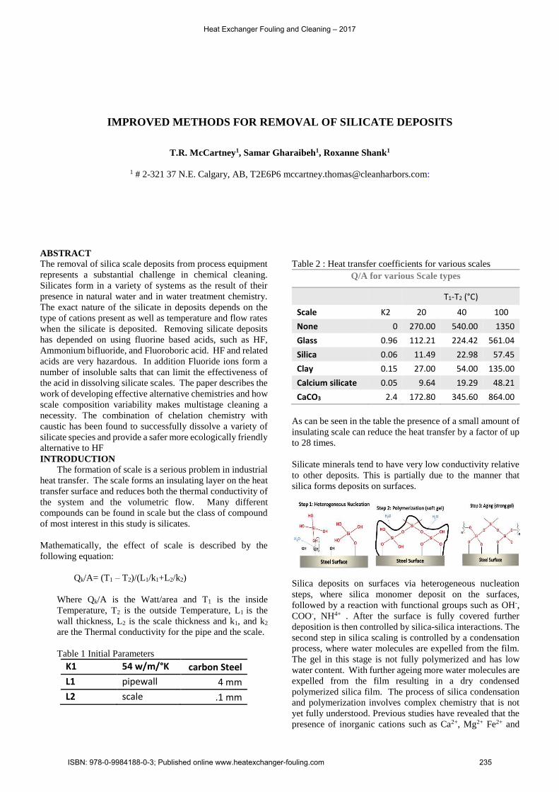
Table 2 : Heat transfer coefficients for various scales
Q/A for various Scale types
T1-T2 (°C)
Scale K2 20 40 100
None 0 270.00 540.00 1350
Glass 0.96 112.21 224.42 561.04
Silica 0.06 11.49 22.98 57.45
Clay 0.15 27.00 54.00 135.00
Calcium silicate 0.05 9.64 19.29 48.21
CaCO3 2.4 172.80 345.60 864.00
As can be seen in the table the presence of a small amount of
insulating scale can reduce the heat transfer by a factor of up
to 28 times.
Silicate minerals tend to have very low conductivity relative
to other deposits. This is partially due to the manner that
silica forms deposits on surfaces.
Silica deposits on surfaces via heterogeneous nucleation
steps, where silica monomer deposit on the surfaces,
followed by a reaction with functional groups such as OH-,
COO-, NH4+ . After the surface is fully covered further
deposition is then controlled by silica-silica interactions. The
second step in silica scaling is controlled by a condensation
process, where water molecules are expelled from the film.
The gel in this stage is not fully polymerized and has low
water content. With further ageing more water molecules are
expelled from the film resulting in a dry condensed
polymerized silica film. The process of silica condensation
and polymerization involves complex chemistry that is not
yet fully understood. Previous studies have revealed that the
presence of inorganic cations such as Ca2+, Mg2+ Fe2+ and
Heat Exchanger Fouling and Cleaning – 2017
ISBN: 978-0-9984188-0-3; Published online www.heatexchanger-fouling.com 235
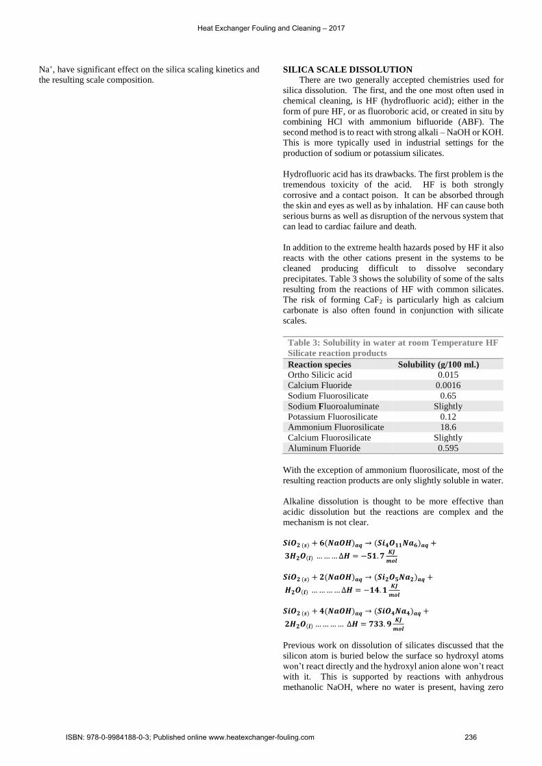
Na+, have significant effect on the silica scaling kinetics and
the resulting scale composition. SILICA SCALE DISSOLUTION
There are two generally accepted chemistries used for
silica dissolution. The first, and the one most often used in
chemical cleaning, is HF (hydrofluoric acid); either in the
form of pure HF, or as fluoroboric acid, or created in situ by
combining HCl with ammonium bifluoride (ABF). The
second method is to react with strong alkali – NaOH or KOH.
This is more typically used in industrial settings for the
production of sodium or potassium silicates.
Hydrofluoric acid has its drawbacks. The first problem is the
tremendous toxicity of the acid. HF is both strongly
corrosive and a contact poison. It can be absorbed through
the skin and eyes as well as by inhalation. HF can cause both
serious burns as well as disruption of the nervous system that
can lead to cardiac failure and death.
In addition to the extreme health hazards posed by HF it also
reacts with the other cations present in the systems to be
cleaned producing difficult to dissolve secondary
precipitates. Table 3 shows the solubility of some of the salts
resulting from the reactions of HF with common silicates.
The risk of forming CaF2 is particularly high as calcium
carbonate is also often found in conjunction with silicate
scales.
Table 3: Solubility in water at room Temperature HF
Silicate reaction products
Reaction species Solubility (g/100 ml.)
Ortho Silicic acid 0.015
Calcium Fluoride 0.0016
Sodium Fluorosilicate 0.65
Sodium Fluoroaluminate Slightly
Potassium Fluorosilicate 0.12
Ammonium Fluorosilicate 18.6
Calcium Fluorosilicate Slightly
Aluminum Fluoride 0.595
With the exception of ammonium fluorosilicate, most of the
resulting reaction products are only slightly soluble in water.
Alkaline dissolution is thought to be more effective than
acidic dissolution but the reactions are complex and the
mechanism is not clear.
𝑺𝒊𝑶𝟐 (𝒔) + 𝟔(𝑵𝒂𝑶𝑯)𝒂𝒒 → (𝑺𝒊𝟒𝑶𝟏𝟏𝑵𝒂𝟔)𝒂𝒒 +
𝟑𝑯𝟐𝑶(𝒍) … … … ∆𝑯 = −𝟓𝟏. 𝟕𝑲𝑱
𝒎𝒐𝒍
𝑺𝒊𝑶𝟐 (𝒔) + 𝟐(𝑵𝒂𝑶𝑯)𝒂𝒒 → (𝑺𝒊𝟐𝑶𝟓𝑵𝒂𝟐)𝒂𝒒 +
𝑯𝟐𝑶(𝒍) … … … … ∆𝑯 = −𝟏𝟒. 𝟏𝑲𝑱
𝒎𝒐𝒍
𝑺𝒊𝑶𝟐 (𝒔) + 𝟒(𝑵𝒂𝑶𝑯)𝒂𝒒 → (𝑺𝒊𝑶𝟒𝑵𝒂𝟒)𝒂𝒒 +
𝟐𝑯𝟐𝑶(𝒍) … … … … ∆𝑯 = 𝟕𝟑𝟑. 𝟗𝑲𝑱
𝒎𝒐𝒍
Previous work on dissolution of silicates discussed that the
silicon atom is buried below the surface so hydroxyl atoms
won’t react directly and the hydroxyl anion alone won’t react
with it. This is supported by reactions with anhydrous
methanolic NaOH, where no water is present, having zero
Heat Exchanger Fouling and Cleaning – 2017
ISBN: 978-0-9984188-0-3; Published online www.heatexchanger-fouling.com 236
rates of reaction. The concentration of NaOH is important;
the rate increases as NaOH increases to a maximum of 15%
at which point the amount of water present becomes a
limiting reaction.
It is important to note for the purposes of this study that these
kinetic results are for SiO2 and not for the complex mixtures
found in real industrial deposits.
Experiments and Results
To study silicates we first had to look at the range of
silicate materials we had in our sample archive.
We chose five samples representing four different systems.
Table 4: Sample source and description
Sample
#
Source Description
1 Silicates Storage tank –
paper mill
Hard white solid
2 Silicates storage tank –
silicate manufacturer
Hard white solid
3 Evaporator tube – SAGD
horizontal evaporator
Brown and white
flakes
4 Evaporator Walls –
SAGD horizontal
evaporator
Shiny brown
blacks
5 Exchanger tube – pilot
plant Mechanical vapour
compression evaporator
Soft grey deposit
Each sample was analyzed to determine its composition. The
analysis was carried out as a combination of chemical
extraction as well as XRD and XRF.
Table 5: Sample compositions Wt. % for sample #
Compound Chemical Formula 1 2 3 4 5
Clinoptilolite Si14.52Al3.48 3.3 7.4
Zeolite K6Na3(Al9Si27) 2.4 3.9
Kanemite Si2NaO8H8 77.2 68.7
Cristobalite SiO2 5.7
Wairakite CaSi4Al2O 53.1 19.4
Wairakite CaSi4Al2O14H4 41.2
Analcime Na2Si4Al2O14H 8.2
Phillipsite Na2K.5Al2.5Si5.5O21H2 24.6
Calcite CaCO3 18
Mg Silicate Ca0.36Na0.56Mg0.81)(Mg0.73Si0.27)Si2O6
18
Magnetite Fe3O4 2
Hydroxyapatite Ca5(PO4)3(OH) 2
Amorphous 17 19.9 41.2 47.8 60
Chemical analysis showed all of the deposits to contain at
least 40% Si.
Our first study was with our existing chemistry which was
10% sodium hydroxide with 5% DPTA. This was compared
with 15% sodium Hydroxide. The samples used in this and
subsequent development rounds were Samples 1 and 2. This
was because we did not have sufficient evaporator samples
to do development work and Samples 1 and 2 were in large
amounts and nearly identical in composition. The results of
the first test was only 30% of the sample dissolved in the 10%
NaOH and 40% in the 15% in 48 hours at 70°C
The next round of tests were performed under the same static
conditions of 70°C and 48 hours of contact time and 15%
NaOH.
Table 6: Chelating agents
Blen
d # Chelant (5%)
%
Dissolved
1 N-{2-[Bis(carboxymethyl)amino]ethyl}-N-(2-hydroxyethyl)glycine 66
2 Isoserine-N,N-diaceticacid trisodium salt 62
3 Poly phosphonate 60
4 Tetrasodium EDTA 57
5 Trisodium salt of methylglycinediacetic acid 52
6 Poly phosphonate 46
7 Na5DPTA 36
8 Sodium Glucoheptonate 33
9 Tetrasodium Glutamate Diacetate 32
10 Di sodium EDTA 9
11 Trisodium HEDTA 8
12 Pentasodium DPTA 6
While the results were encouraging we decided to try to see
if we could improve the amount of solids dissolved.
Table7: effect of polycarboxylate on overall performance
Chelant po
lycarbo
xylate A
wt%
Diso
lved
po
lycarbo
xylate B
wt%
Diso
lved
po
lycarbo
xylate C
wt%
Diso
lved
N-{2-[Bis(carboxymethyl)amino]ethyl}-N-(2-hydroxyethyl)glycine
43 7 18
Isoserine-N,N-diaceticacid trisodium salt 31 88 62
Poly phosphonate 22 85 11
Tetrasodium EDTA 10 8 24
Trisodium salt of methylglycinediacetic acid
22 82 7
Poly phosphonate - - -
Heat Exchanger Fouling and Cleaning – 2017
ISBN: 978-0-9984188-0-3; Published online www.heatexchanger-fouling.com 237
As can be seen in the table combinations of the chelating
agents with the poly carboxylates gave a substantial
improvement in the amount of silicate dissolved, at least in a
couple combinations.
Based on the study of the simpler silicate mixes we settled on
the use of Polycarboxylate B and then tested that against a
variety of chelants on samples 3, 4 and 5.
The initial tests with the solutions that worked well in the
simpler samples showed them to be ineffective on the oilfield
scale.
Table 8: effect of surfactant addition
Solution % dissolved
No surfactant
% dissolved 0.2%
surfactant
Glucoheptonate (5%) PC (10%)
12 61
Versene HEDTA (5%) PC (10%)
0 66
DTPA (5%) PC (10%) 0 72
MDGA (5%) PC (10%) 0 58
As can be seen in the table the addition of a surfactant
substantially improved the dissolution of the oilfield scale.
We settled on a blend of Polymer B and MDGA (exp-S1) and
tested the effect of chelant concentration on the dissolution
of the scale
Table 9: test of concentration effect
EXP-S1 (wt. %) NaOH % Dissolved
0 15% 30
3 15% 88
5 15% 93
7 15% 95
10 15% 80
15 15% 85
Increased polymer/chelant shows a maximum at around 7%
of the combined solution, with a fall off beyond that.
Scale dissolution for these complex deposits could further be
improved by using a multistage process of first dissolving the
scale with a strong acid (HCl or methane sulfonic) then
dissolving with a combination of caustic chelants and
surfactants.
DISCUSSION
We theorize that the addition of the chelating agents prevents
the secondary reactions of the divalent cations with OH- at
the reaction surface allowing the OH- to react with the silicate
backbone of the deposit.
Several important questions remain unanswered.
What influence does the molecular weight of the poly
carbonate have on the chelate performance? We know that
the polycarboxylates have molecular weights where A<B<C
So there is no direct correlation of the weight to effectiveness.
Why does the reaction efficiency decrease with increasing
combined chelant/polycarboxylate after reaching maxima? It
may have to do with reaching a maximum in the activity of
the solution but in a solution with 15% NaOH as a base, small
changes in the chelate concentration should not influence the
ionic strength of the solution significantly.
In complex scales taken from oilfield systems the reaction
rate appears to be limited by the secondary precipitates
present. Layers of iron oxide slow or stop the reaction – so
is it possible to use chelant - reducing agent combinations to
permit the simultaneous dissolving of the silicate and the
oxides?
CONCLUSIONS
This work shows conclusively that concentrated NaOH
solutions can be combined with chelating agents to dissolve
complex silicate deposits.
Systems containing more than silicates require additional
treatments specific to the secondary deposits. This is true
even for HF dissolution and often ignored.
Safety and environmental hazards can be substantially
improved by moving away from HF.
Heat Exchanger Fouling and Cleaning – 2017
ISBN: 978-0-9984188-0-3; Published online www.heatexchanger-fouling.com 238
REFERENCES
Brady E. L., "Chemical Nature of Silica Carried by
Steam," The Journal of Physical Chemistry, vol. 57, no. 7,
p. 706–710, 1953.
Baoxia Mi M. E., "Silica Scaling and scaling reversibility
in forward osmosis," Desalination, vol. 312, pp. 75-81,
2013.
Brinker J., Scherer G., Sol-Gel Science, Boston, MA:
Academic Press, 1990
Fertani-Gmati M., Brahim K., Khattech I., Jemal M.,
"Thermochemistry and kinetics of silica dissolution in
NaOH solutions: Effect of the alkali concentration,"
Thermochimica Acta, vol. 594, pp. 58-67, 2014.
Fertani-Gmati M., Jemal M., "Thermochemistry and
Kinetics of silica dissolution in NaOH aqueous solution,"
Thermochimica Acta, vol. 513, pp. 43-48, 2011
Hooley J. G., "The Kinetics of the Reaction of Silica with
Group I Hydroxides," Canadian Journal of Chemistry, vol.
39, pp. 1221-1230, 1961.
Iler, R.K. “Chemistry of Silica: solubility, polymerization
and surface properties and Biochemistry” J. Wiley and
Sons Inc., New York , 1979
Jasmund K., "Thermodynamic Behavior of Quartz and
Other Forms of Silica in Pure Water at Elevated
Temperatures and Pressures with Conclusion on Their
Mechanism of Solution: A Discussion," The Journal of
Geology, vol. 66, no. 5, pp. 595-596, 1958.
Sahachaiyunta P.,. Koo T, Sheikholeslami R., "Effect of
several inorganic species on silica fouling in RO
membranes," Desalination, vol. 144, no. 1-3, p. 373–378,
2002.
Sheikholeslami R.,. Al-Mutaz I,. Koo T, Young A.,
"Pretreatment and the effect of cations and anions on
prevention of silica fouling," Desalination, vol. 139, no. 1–
3, pp. 83-95, 2001..
Heat Exchanger Fouling and Cleaning – 2017
ISBN: 978-0-9984188-0-3; Published online www.heatexchanger-fouling.com 239