Embed Size (px)
Citation preview

MIAU
Improved Oil Recovery by Injection of Water and Gas
Dr. Amin Azhdarpour
Depar tment Of Pet ro leum Eng ineer ing , Marvdasht Branch, Is lamic Azad Un ivers i ty, Marvdasht , I ran .
E-mai l : aminazh22@gmai l .com;amin [email protected]. i r
MIAU
Chapter 2
PRINCIPALS OF WATER FLOODING
2
MIAU
Course content Water flooding definition and basics
Factors to consider in waterflooding
Review of rock properties and fluid flow
Effect of trapped gas on waterflooding
Water sources for waterflooding
Water treatment
Flooding pattern
The Fractional Flow Equation
Recovery calculations
Water injection rate determination
Improved Waterflooding Processes
3
MIAU
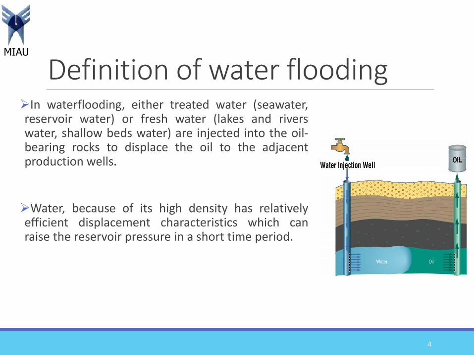
Definition of water floodingIn waterflooding, either treated water (seawater,reservoir water) or fresh water (lakes and riverswater, shallow beds water) are injected into the oil-bearing rocks to displace the oil to the adjacentproduction wells.
Water, because of its high density has relativelyefficient displacement characteristics which canraise the reservoir pressure in a short time period.
4
MIAU
Why water flooding?
The primary reasons why waterflooding is the most successful and most widely used oil recovery process are:
general availability of water
low cost as compared to other injection fluids
ease of injecting water into a formation
high efficiency with which water displaces oil
5
MIAU
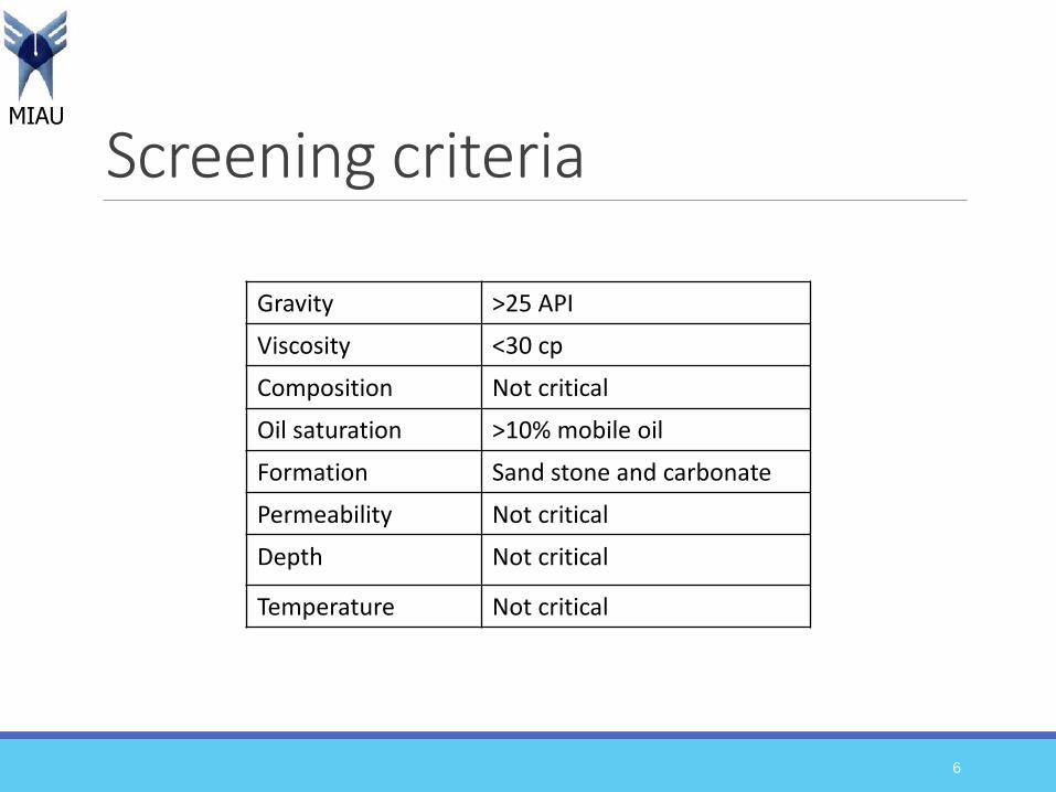
Screening criteria
6
Gravity >25 API
Viscosity <30 cp
Composition Not critical
Oil saturation >10% mobile oil
Formation Sand stone and carbonate
Permeability Not critical
Depth Not critical
Temperature Not critical

MIAU
Water flooding versus pressure maintenance
In both instances, the injected water displaces oil and is a dynamicdisplacement process.
When water injection commences at a time in the life of a reservoirwhen the reservoir pressure is at a high level, the injection isfrequently referred to as a pressure maintenance project.
On the other hand, if water injection commences at a time whenreservoir pressure has declined to a low level due to primary depletion,the injection process is usually referred to as a waterflood.
7
MIAU
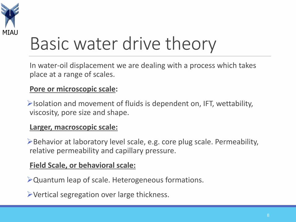
Basic water drive theory In water-oil displacement we are dealing with a process which takes place at a range of scales.
Pore or microscopic scale:
Isolation and movement of fluids is dependent on, IFT, wettability, viscosity, pore size and shape.
Larger, macroscopic scale:
Behavior at laboratory level scale, e.g. core plug scale. Permeability, relative permeability and capillary pressure.
Field Scale, or behavioral scale:
Quantum leap of scale. Heterogeneous formations.
Vertical segregation over large thickness.
8

MIAU
Water Oil Displacement at Microscopic and Macroscopic levels
9
MIAU
Factors to consider in waterflooding1. Reservoir geometry
2. Fluid properties
3. Reservoir depth
4. Lithology and rock properties
5. Fluid saturations
6. Reservoir uniformity and pay continuity
7. Primary reservoir driving mechanisms
10
MIAU
1. Reservoir geometry
An analysis of reservoir geometry and past reservoir performance isoften important when defining the presence and strength of a naturalwater drive and, thus, when defining the need to supplement thenatural injection.
If a water-drive reservoir is classified as an active water drive,injection may be unnecessary.
11
MIAU
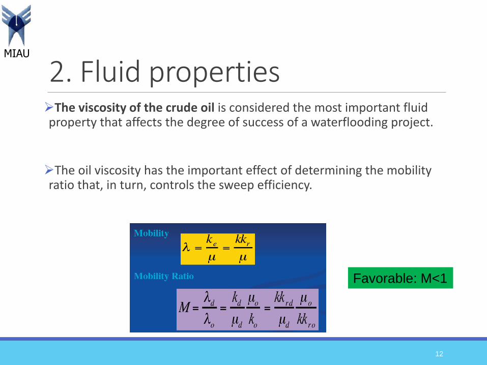
2. Fluid properties The viscosity of the crude oil is considered the most important fluid property that affects the degree of success of a waterflooding project.
The oil viscosity has the important effect of determining the mobility ratio that, in turn, controls the sweep efficiency.
12
Favorable: M<1
MIAU
3. Reservoir depth Maximum injection pressure will increase with depth.
On the other hand, a shallow reservoir imposes a restraint on theinjection pressure that can be used, because this must be less thanfracture pressure.
In waterflood operations, there is a critical pressure (approximately 1psi/ft of depth) that, if exceeded, permits the injecting water to expandopenings along fractures or to create fractures. This results in thechanneling of the injected water or the bypassing of large portions ofthe reservoir matrix.
Consequently, an operational pressure gradient of 0.75 psi/ft of depthnormally is allowed to provide a sufficient margin of safety to preventpressure parting.
13
MIAU
4. Lithology and rock propertiesReservoir lithology and rock properties that affect flood ability andsuccess are:
Porosity: In some complex reservoir systems, only a small portion of thetotal porosity, such as fracture porosity, will have sufficient permeability tobe effective in water-injection operations.
Permeability: Low-permeability reservoirs possess water-injection problemsin terms of the desired water injection rate or pressure.
Clay content: clay minerals present in some sands may clog the pores byswelling.
Net thickness: in a tight or thin reservoir, the required injection pressuremight exceed the formation fracture pressure.
14
MIAU
5. Fluid saturation In determining the suitability of a reservoir for waterflooding, a highoil saturation that provides a sufficient supply of recoverable oil is theprimary criterion for successful flooding operations.
Note that higher oil saturation at the beginning of flood operationsincreases the oil mobility that, in turn, gives higher recovery efficiency.
15
MIAU
6. Reservoir uniformity and pay continuity
Substantial reservoir uniformity is one of the major physical criterionsfor successful waterflooding.
if the formation contains a layer of limited thickness with a very highpermeability (thief zone), rapid channeling and bypassing will develop.
Breaks in pay continuity and reservoir anisotropy caused bydepositional conditions, fractures, or faulting need to be identified anddescribed before implementing the waterflood.
16

MIAU
7. Primary reservoir driving mechanisms
Water-drive reservoirs: not good candidates for water flooding.
Gas-cap reservoirs: not normally good waterflood prospects. Onlywhen gas cap is very small and there is no good vertical connectivitybetween gas cap and oil.
Solution gas-drive: generally are considered the best candidates forwaterfloods.
17

MIAU
Review of rock properties and fluid flow1. Wettability
2. Capillary pressure
3. Relative permeability
18

MIAU
1. Wettability In a rock/oil/brine system, wettability can be defined as the tendency of a fluid to preferentially adhere to, or wet, the surface of a rock in the presence of other immiscible fluids.
19
MIAU
Importance of wettabilityThe performance of a waterflood is controlled to a large extent bywettability. Reasons for this are:
1. Location, flow, and distribution of fluids is affected by wettability.Wetting phase occupies the smallest pores and non-wetting phase goesto the center of larger pores. Therefore, a waterflood in a water-wetreservoir will yield a higher oil recovery at a lower water-oil ratio (WOR)than an oil-wet reservoir.
2. It is necessary to know the wettability of the reservoir. Waterflood in awater-wet reservoir is an imbibition process; whereas in an oil-wetreservoir, it would be a drainage process.
20
MIAU
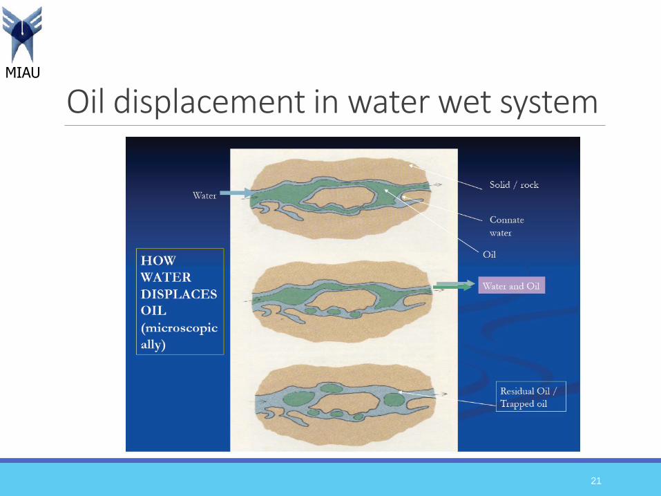
Oil displacement in water wet system
21
MIAU
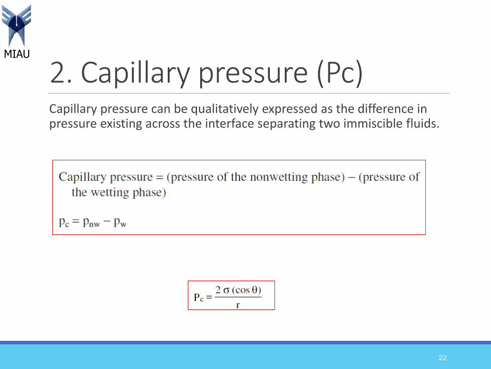
2. Capillary pressure (Pc) Capillary pressure can be qualitatively expressed as the difference in pressure existing across the interface separating two immiscible fluids.
22
MIAU
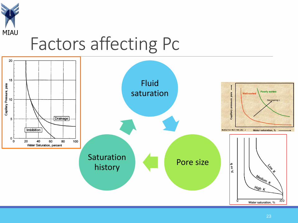
Factors affecting Pc
Fluid saturation
Pore sizeSaturation
history
23
MIAU
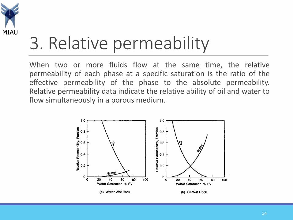
3. Relative permeability When two or more fluids flow at the same time, the relativepermeability of each phase at a specific saturation is the ratio of theeffective permeability of the phase to the absolute permeability.Relative permeability data indicate the relative ability of oil and water toflow simultaneously in a porous medium.
24

MIAU
Importance of relative permeability
Wettability
Fluid saturation
Saturation history
Fluid distribution
25
Imbibition process to produce
original fluid saturation:
• Inject water
• Inject oil
• Reinject water
MIAU
Optimum time to waterfloodThe key parameter: Sufficient oil must remain in the reservoir after primary operations have ceased to justify the waterflooding.
1. Reservoir oil viscosity: Water injection should be initiated when thereservoir pressure reaches its bubble-point pressure since the oilviscosity reaches its minimum value at bubble-point pressure. Themobility of the oil will increase with decreasing oil viscosity, which inturns improves the sweeping efficiency.
2. Free gas saturation: It is desirable to have initial gas saturation,possibly as much as 10%. This will occur at a pressure that is belowthe bubble point pressure.
3. Productivity of producing wells: A high reservoir pressure isdesirable to increase the productivity of producing wells, whichprolongs the flowing period of the wells and decreases lifting costs.
26
MIAU
Cont…4. Cost of injection equipment: This is related to reservoir pressure,
and at higher pressures, the cost of injection equipment increases.Therefore, a low reservoir pressure at initiation of injection isdesirable.
5. Effect of delaying investment on the time value of money: Adelayed investment in injection facilities is desirable from thisstandpoint.
Some of these factors act in opposition to others. Thus the actual pressure at which a fluid injection project should be initiated will require optimization of the various factors in order to develop the most favorable overall economics.
27
MIAU
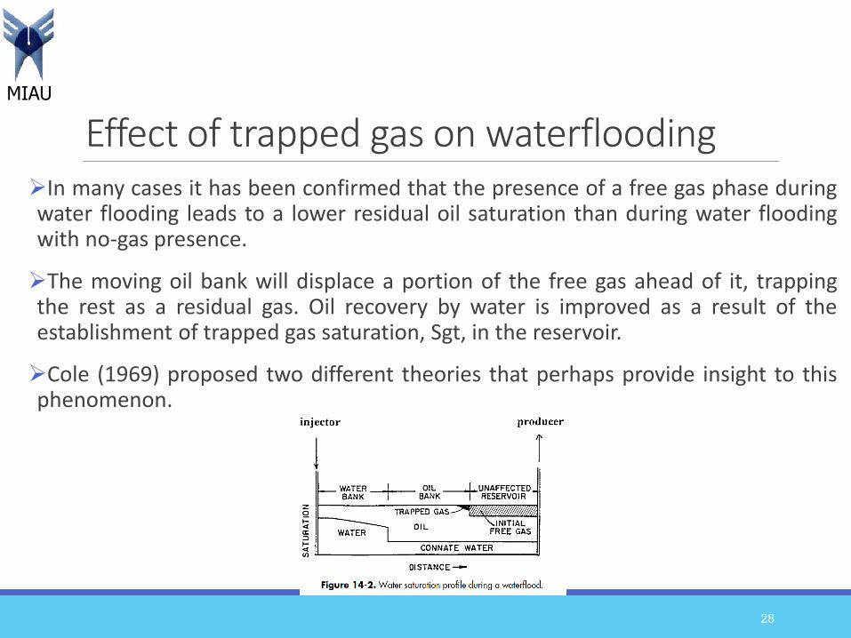
Effect of trapped gas on waterfloodingIn many cases it has been confirmed that the presence of a free gas phase duringwater flooding leads to a lower residual oil saturation than during water floodingwith no-gas presence.
The moving oil bank will displace a portion of the free gas ahead of it, trappingthe rest as a residual gas. Oil recovery by water is improved as a result of theestablishment of trapped gas saturation, Sgt, in the reservoir.
Cole (1969) proposed two different theories that perhaps provide insight to thisphenomenon.
28
MIAU
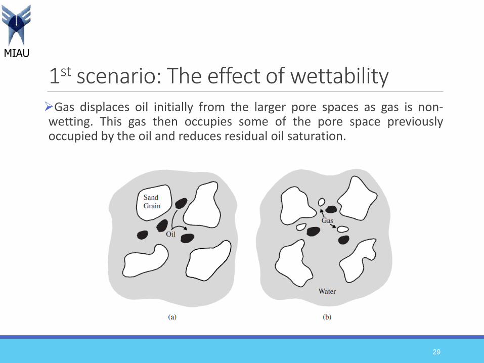
1st scenario: The effect of wettability Gas displaces oil initially from the larger pore spaces as gas is non-wetting. This gas then occupies some of the pore space previouslyoccupied by the oil and reduces residual oil saturation.
29
MIAU
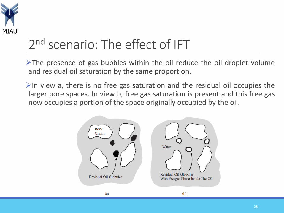
2nd scenario: The effect of IFTThe presence of gas bubbles within the oil reduce the oil droplet volumeand residual oil saturation by the same proportion.
In view a, there is no free gas saturation and the residual oil occupies thelarger pore spaces. In view b, free gas saturation is present and this free gasnow occupies a portion of the space originally occupied by the oil.
30
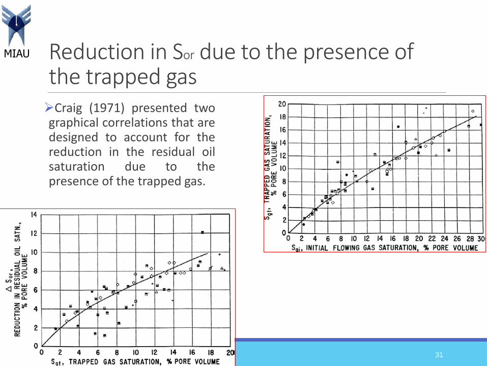
MIAU Reduction in Sor due to the presence of the trapped gasCraig (1971) presented twographical correlations that aredesigned to account for thereduction in the residual oilsaturation due to thepresence of the trapped gas.
31

MIAU
Cont…
32
MIAU
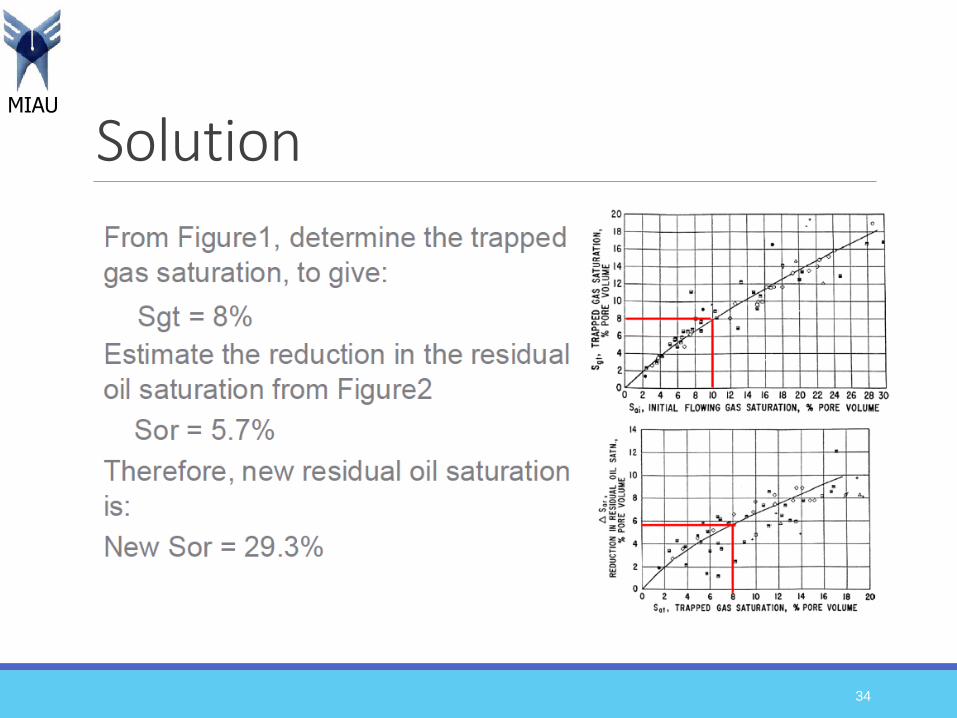
An oil reservoir is being considered for further development byinitiating a waterflooding project. The oil–water relative permeabilitydata indicate that the residual oil saturation is 35%. It is projected thatthe initial gas saturation at the start of the flood is approximately 10%.Calculate the anticipated reduction in residual oil, ΔSor, due to thepresence of the initial gas at the start of the flood.
33
Example
MIAU
Solution
34
MIAU
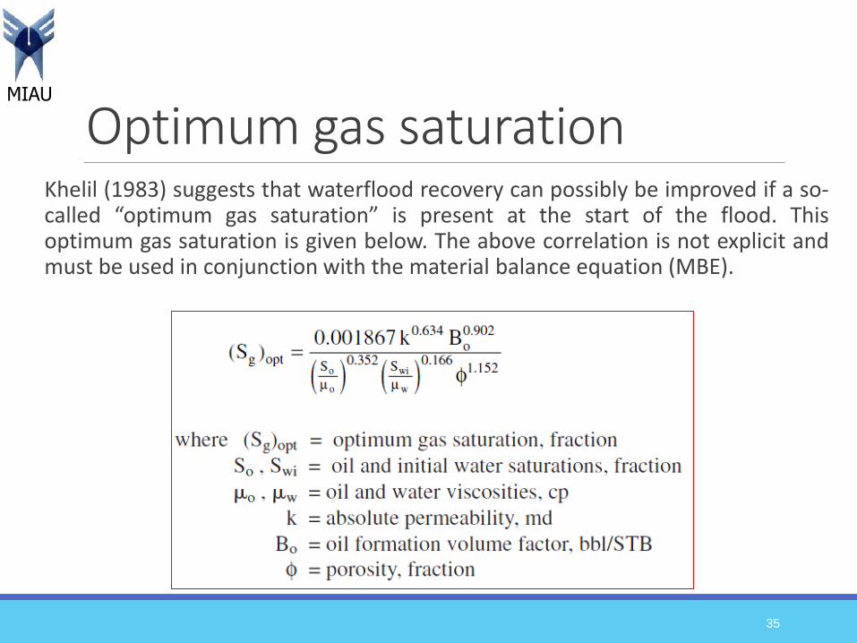
Optimum gas saturation Khelil (1983) suggests that waterflood recovery can possibly be improved if a so-called “optimum gas saturation” is present at the start of the flood. Thisoptimum gas saturation is given below. The above correlation is not explicit andmust be used in conjunction with the material balance equation (MBE).
35
MIAU
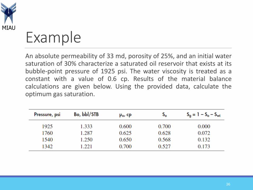
Example An absolute permeability of 33 md, porosity of 25%, and an initial watersaturation of 30% characterize a saturated oil reservoir that exists at itsbubble-point pressure of 1925 psi. The water viscosity is treated as aconstant with a value of 0.6 cp. Results of the material balancecalculations are given below. Using the provided data, calculate theoptimum gas saturation.
36
MIAU
Solution
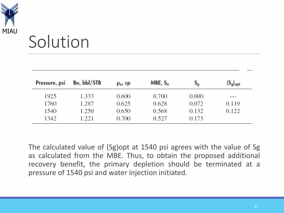
The calculated value of (Sg)opt at 1540 psi agrees with the value of Sgas calculated from the MBE. Thus, to obtain the proposed additionalrecovery benefit, the primary depletion should be terminated at apressure of 1540 psi and water injection initiated.
37
MIAU
Water sources for waterflooding
Fresh water
sources
Salt water sources
38
MIAU
1. Fresh water sourcesFresh water can be injected to formations, however, clay swelling is one of themajor challenges associated with this method. Increasing the salinity of thewater usually minimizes this effect.
Fresh water sources are:Surface waters held in rivers or lakes: Undesirable qualities of containing large
amounts of oxygen, a high level of suspended solids (sands, animal, vegetableproducts and bacteria). They require considerable amount of filtration equipment.
Alluvial waters trapped by shallow wells in the vicinity of surface wateraccumulations: The advantage is that they have been naturally filtered but still aresubject to surface contamination.
Permeable shallow reservoirs: their use is restricted to the provision of potable waterin many areas.
Oxygen must be removed from the water because it promotes corrosion and growth ofcertain bacteria. Adding an oxygen scavenging agent such as sodium bisulfite andammonium bisulphite.
39
MIAU
2. Salt water sources In the vicinity of oil reservoirs there are often deep, salt water bearingformations. The water may be pumped to surface and in general requires theleast extensive treatments.
Sea water may also be used. Sea water is usually corrosive and requiretreatment to reduce its corrosiveness.
The precipitation of sulphates is the most damaging scenario, since they arenot soluble in solvents or acids. Thus, the use of polyphosphates helps to avoidsulphate precipitation in the reservoirs.
The following pairs of ions may form precipitates: Barium and sulphate
Calcium and sulphate
Calcium and carbonate
Iron and sulphur
Iron and oxygen
40
MIAU
Water treatment The objectives of water treatment are:
1. To avoid plugging the reservoir due to: Suspended solids
Corrosion
Bacteria (the most damaging being sulphate reducing bacteria)
The incompatibility of the water and formation damage
2. To avoid the corrosion of the injection system Due to the presence of gas dissolved in the water: H2S, CO2 and oxygen
3. To avoid the swelling of shales Due to exchange of ion between shale and water
41
MIAU
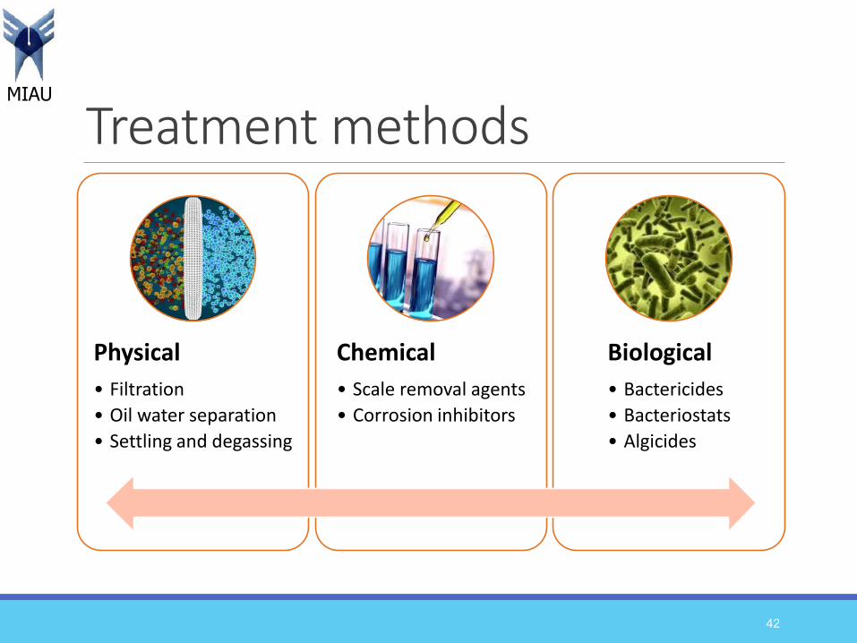
Treatment methods
Physical
• Filtration
• Oil water separation
• Settling and degassing
Chemical
• Scale removal agents
• Corrosion inhibitors
Biological
• Bactericides
• Bacteriostats
• Algicides
42
MIAU
Physical treatment Filtration: the basic types of filters are standard sand packs (downwardflow), special sand packs (upward flow), diatomaceous earth (the mostefficient) and disposable cartridge filters.
Oil water separation: depending on the percentage of water anddegree of separation required, dehydrators, free water separators orwash tanks may be used.
Settling: for the deposition of sediments.
Elimination of dissolved gases (CO2, H2S, O2):Stripping with neutral or inert gas by countercurrent flow in a closed column
through which the water passes slowly.
Vacuum degassing
43

MIAU
Chemical treatment Acids and chemicals are used to remove mineral salt deposits such ascalcium carbonate, calcium sulfate, barium sulfate or iron sulfide.
However, acids are corrosive and hazardous. In addition, chemicaltreatments are expensive and may not be cost-effective or successful.
Alkyl and aryl high molecular weight amine salts and certaincondensed ethylene oxide-amines are the common types of chemicalsused for treating water.
44

MIAU
Microbial treatment Biocides are divided into three main categories:Electrophilic Biocides. These biocides react with electron rich chemical
groups.
Membrane Active / Lytic Biocides. Quaternaries are a broad group ofmembrane active biocides that include both quaternary ammonium andquaternary phosphonium compounds.
Miscellaneous Biocides. Such as 2-(tertiary butylamino)-4-chloro-6-ethylamino-s-triazine (terbuthylazine [TBZ]).
Biocides are mainly used for sulphate reducing bacteria (SRB) to prevent ironsulfide precipitation. SRB activity in the oil field’s water injection systemcauses corrosion due to H2S production.
45
MIAU
Selection of flooding pattern The objective is to select the proper pattern that will provide theinjection fluid with the maximum possible contact with the crude oilsystem. This selection can be achieved by (1) converting existingproduction wells into injectors or (2) drilling infill injection wells.
When making the selection, the following factors must be considered:Reservoir heterogeneity and directional permeability
Direction of formation fractures
Availability of the injection fluid (gas or water)
Desired and anticipated flood life
Maximum oil recovery
Well spacing, productivity, and injectivity
46
MIAU
Flooding patterns The location of injection and production well is called flooding pattern.
Essentially four types of well arrangements are used in fluid injectionprojects:
1. Irregular injection patterns
2. Peripheral injection patterns
3. Regular injection patterns
4. Basal injection patterns
47
MIAU
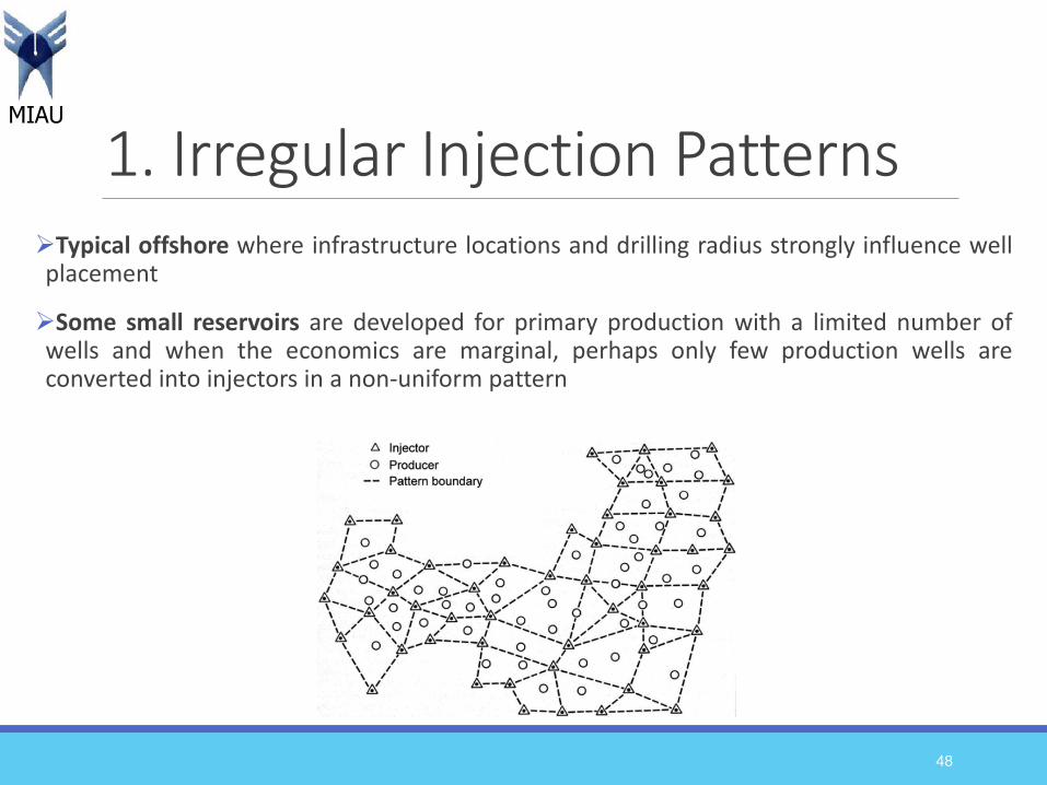
1. Irregular Injection PatternsTypical offshore where infrastructure locations and drilling radius strongly influence wellplacement
Some small reservoirs are developed for primary production with a limited number ofwells and when the economics are marginal, perhaps only few production wells areconverted into injectors in a non-uniform pattern
48
MIAU
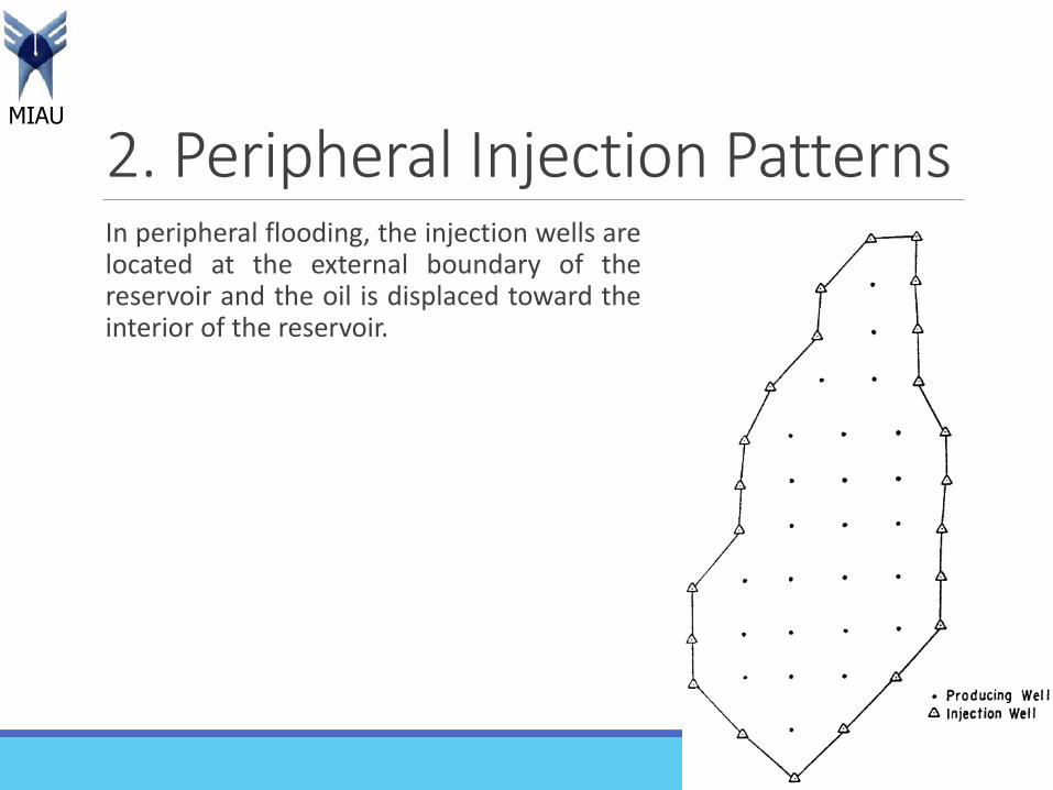
2. Peripheral Injection PatternsIn peripheral flooding, the injection wells arelocated at the external boundary of thereservoir and the oil is displaced toward theinterior of the reservoir.
49
MIAU
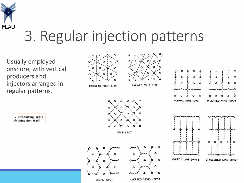
3. Regular injection patterns
Usually employed onshore, with vertical producers and injectors arranged in regular patterns.
50
MIAU
Cont…Direct line drive: The lines of injection and production are directly opposed to each other. Thepattern is characterized by the distance between wells of the same type, and the distance betweenlines of injectors and producers.
Staggered line drive: The wells are in lines as in the direct line, but the injectors and producers are nolonger directly opposed.
Five spot: This is a special case of the staggered line drive in which the distance between all like wellsis constant. Any four injection wells thus form a square with a production well at the center.
Seven spot: The injection wells are located at the corner of a hexagon with a production well at itscenter.
Nine spot: This pattern is similar to that of the five spot but with an extra injection well drilled at themiddle of each side of the square. The pattern essentially contains eight injectors surrounding oneproducer.
The patterns termed inverted have only one injection well per pattern. This is the difference between normal and inverted well arrangements.
51

MIAU
4. Basal injection patterns
In basal injection, the fluid is injected atthe bottom of the structure. Many water-injection projects use basal injectionpatterns with additional benefits beinggained from gravity segregation.
52
MIAU
Water flooding- Rule of thumb1. Water requirements: 1.5 to 2 pore volumes.
2. Typical injection rates: 5 to 10 bbl/day ft of reservoir for patternflooding. A higher rate of 10-20 bbl/day ft can be anticipated toraquifer injection.
3. Injection rates for carbonate reservoirs should run two to threetimes higher than for sandstones.
4. Response to flood can be expected when two thirds of the fill-up hasbeen achieved (i.e., when two thirds of the voidage created byprimary production is filled by the water injected).
53
MIAU
Cont…5. Peak oil production rete is reached at the time of fill-up.
6. Gross production rate equals 80% of water injection rate. The rest of theinjected water is lost outside of the patterns or to the aquifer.
7. Incremental recovery due to waterflooding is equal to the primary recoveryfor crude oils having gravities above 30 API. For lower crude oil gravities (15-30 API), the incremental recovery ranges from 50 to 100% of primaryrecovery.
54
MIAU
Limitations of waterflooding Compatibility of the planned injected water with the reservoir’sconnate water.
Interaction of the injected water with the reservoir rock (claysensitivities, rock dissolution, or generally weakening the rockframework).
Injection-water treatment to remove oxygen, bacteria, and undesirablechemicals.
The challenges involved in separating and handling the produced waterthat has trace oil content and various scale-forming minerals.
55
MIAU
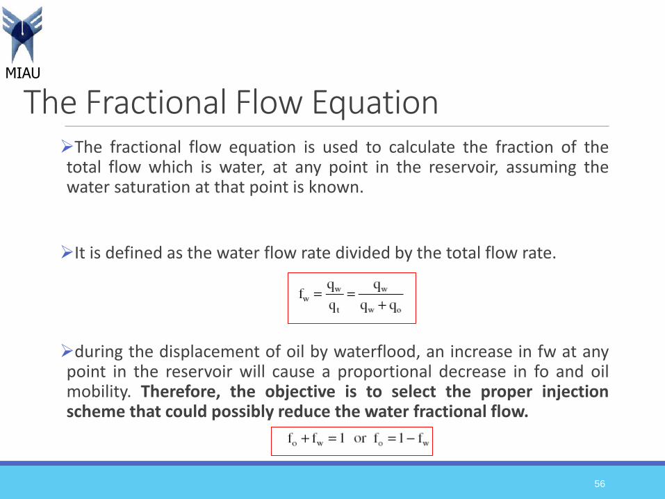
The Fractional Flow EquationThe fractional flow equation is used to calculate the fraction of thetotal flow which is water, at any point in the reservoir, assuming thewater saturation at that point is known.
It is defined as the water flow rate divided by the total flow rate.
during the displacement of oil by waterflood, an increase in fw at anypoint in the reservoir will cause a proportional decrease in fo and oilmobility. Therefore, the objective is to select the proper injectionscheme that could possibly reduce the water fractional flow.
56
MIAU
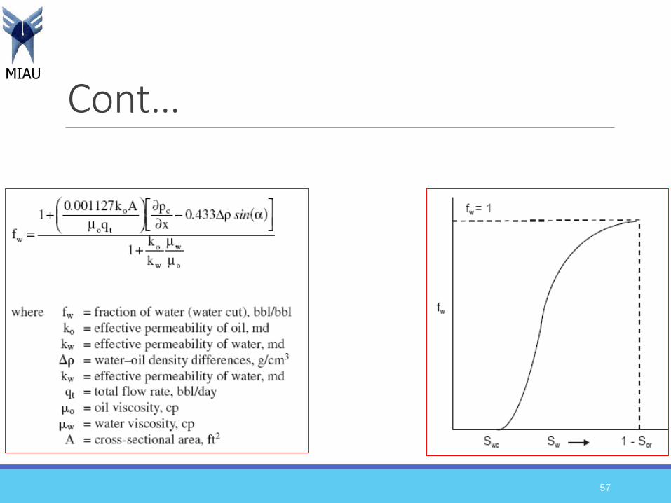
Cont…
57
MIAU
Factors affecting the fractional flow curve
Immiscible displacement of oil by water is affected by several factors including:◦ Wettability
◦ Formation Dip and Direction of Displacement
◦ Capillary Pressure
◦ Oil and Water Mobilities
◦ Injection rate
58

MIAU
1. Effect of wettabilityAt a particular water saturation, theeffective permeability to water, Kw is smallerin a water wet rock than in an oil wet rock.Accordingly, the denominator of fw equationwill be larger and fw will be smaller.
Since it is desirable to minimize fw at aparticular saturation condition, water-wetreservoirs will yield a higher displacementefficiency and higher oil recovery thancomparable oil-wet reservoirs.
59

MIAU
2. Effect of Formation Dip and Direction of Displacement
60
Updip flow: sin α is positive. When the water displaces oil updip (i.e., injection well islocated downdip).
Downdip flow: sin α is negative. When the water displaces oil downdip (i.e., injection wellis located updip).

MIAU
Cont… The effect of formation dip is dictated by the gravity term, Δρsin α.
the effect of gravity is to decrease the displacement efficiency.
When water displaces oil up-dip so that 0 < α < 180, sin α is positive, which leads to a decrease in the fw curve.
Conversely, when 180 < α < 360, i.e., when water displaces oil down-dip, sin α is negative.
The obvious conclusion from these observations is that water should be injected up-dip to obtain maximum oil recovery.
61

MIAU
3. Effect of capillary pressure In a water-wet rock, the capillary pressure gradient will be a positivenumber (according to fw equation); therefore, its effect will be toincrease the value of fw and to decrease the efficiency of thewaterflood.
It would be desirable in a waterflood to decrease, or eliminate, thecapillary pressure gradient. This can be accomplished by altering thewettability of the rock or by decreasing, or eliminating, the interfacialtension between oil and water.
62
MIAU
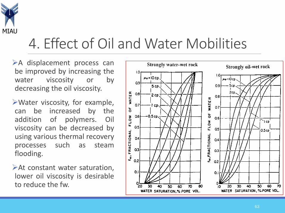
4. Effect of Oil and Water MobilitiesA displacement process canbe improved by increasing thewater viscosity or bydecreasing the oil viscosity.
Water viscosity, for example,can be increased by theaddition of polymers. Oilviscosity can be decreased byusing various thermal recoveryprocesses such as steamflooding.
At constant water saturation,lower oil viscosity is desirableto reduce the fw.
63
MIAU
5. Effect of injection rate The effect of rate varies depending upon whether water is moving up-dip or down-dip.
A low value of qt (according to fw equation) is desirable if water ismoving up-dip. Conversely, a large rate should be used for down-dip displacement.
In general, increasing rate improves the efficiency of downdip floodbut causes lower efficiency in up-dip flood.
64