Embed Size (px)
Citation preview
737
IMPROVED SOLUTION FOR ENCODED PHASED ARRAY UT EXAMINATION OF
DISSIMILAR METAL PIPING WELDS
Johan Berlanger, Dominic Marois, Louis Beaulieu-Charbonneau, Guy Maes,
Zetec 875, boul. Charest Ouest - Suite 100, Québec (Québec), G1N 2C9, Canada
ABSTRACT
Since qualifying its first inspection technique in 2004, ZETEC has continuously worked with the
Electric Power Research Institute (EPRI) to push back the limits of challenging applications. Using
lessons learned from years of field experience, we have now qualified an improved solution for encoded
phased array UT examination of DM piping welds, using either the ZIRCON®, our latest portable PA UT
system, or the powerful DYNARAY® instrument. Controlled by the industry-leading UltraVision
® 3
software, ZETEC’s state-of-the-art instruments allow for better focusing, improved data quality and
increased inspection efficiency.
The procedure for encoded, phased array ultrasonic testing (UT) covers flaw detection, length and
through-wall sizing in dissimilar metal piping welds from the outside surface. The applied inspection
techniques are based on 1.5 MHz 2D matrix array probes. The scope of the procedure ranges from small
diameter nozzles up to the heavy-wall safe-end to nozzle welds that connect steam generators to the main
coolant piping.
The paper will present results obtained on various PDI practice specimens. The performance of the
phased array methodology in terms of detection and sizing shall be clearly illustrated. The importance of
versatile and powerful software to improve the efficiency of the data analysis process shall be addressed,
and various advanced software tools for flaw discrimination, sizing and reporting shall be discussed.
HISTORICAL OVERVIEW
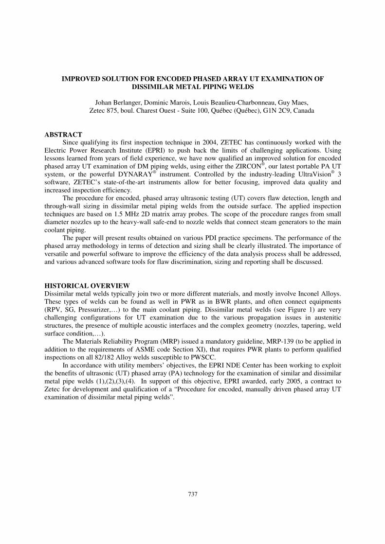
Dissimilar metal welds typically join two or more different materials, and mostly involve Inconel Alloys.
These types of welds can be found as well in PWR as in BWR plants, and often connect equipments
(RPV, SG, Pressurizer,…) to the main coolant piping. Dissimilar metal welds (see Figure 1) are very
challenging configurations for UT examination due to the various propagation issues in austenitic
structures, the presence of multiple acoustic interfaces and the complex geometry (nozzles, tapering, weld
surface condition,…).
The Materials Reliability Program (MRP) issued a mandatory guideline, MRP-139 (to be applied in
addition to the requirements of ASME code Section XI), that requires PWR plants to perform qualified
inspections on all 82/182 Alloy welds susceptible to PWSCC.
In accordance with utility members’ objectives, the EPRI NDE Center has been working to exploit
the benefits of ultrasonic (UT) phased array (PA) technology for the examination of similar and dissimilar
metal pipe welds (1),(2),(3),(4). In support of this objective, EPRI awarded, early 2005, a contract to
Zetec for development and qualification of a “Procedure for encoded, manually driven phased array UT
examination of dissimilar metal piping welds”.
738
Figure 1: Typical dissimilar metal weld (DMW)
Zetec and EPRI successfully conducted this project, and end 2005 provided the industry with a
qualified portable phased array UT system, procedure and qualification data sets, for commercial use (5).
Since the initial qualification, the Zetec/EPRI solution for DM weld inspection has been adopted by
utilities and NDE service vendors worldwide. The procedure has been successfully deployed on site at
multiple occasions. In addition, several organisations and institutes have used similar inspection
techniques in the PINC RRT on mid-thickness DM welds (6). It is fair to say that the Zetec/EPRI
procedure for DM welds is one of the most widely used automated phased array UT procedures.
In 2009, a new revision of the procedure was formally qualified, in collaboration with EPRI/PDI,
introducing improvements from lessons learned during site deployment. These improvements include:
• additional qualified wedge sets, to cover a wide range of site configurations
• updated calibration section that allows for the use of carbon steel velocity and calibration blocks
when performing inspections on similar material
• updated data analysis section with additional guidance for the data analyst when
characterizing/classifying indications
At the same time, several extensions were added to the qualified procedure, for inspection of site
specific configurations.
Early 2011, Zetec successfully qualified an evolution of the procedure using the ZIRCON and
DYNARAY, controlled by UltraVision 3. The benefits resulting from this improved solution will be
addressed in this paper.
PRINCIPLES OF THE PHASED ARRAY EXAMINATION METHOD
General principles
The Zetec/EPRI encoded phased array procedure for dissimilar metal welds prescribes an examination
conducted from the OD, using transmit/receive examination techniques. The phased array probe
assemblies consist of dual 2D matrix arrays, at a nominal frequency of 1.5 MHz, and placed on
exchangeable rexolite wedges. The 2D matrix arrays allow for simultaneous variation of refracted angle
and skew angle whereas the dual (T/R) arrays offer the following benefits: absence of near-surface “dead-
zone”; elimination of “ghost echoes” caused by internal reflections in the wedge; a better sensitivity and
SNR due to the convolution of T and R beams; and an improved inspection capability on various
austenitic steel structures, especially for L-waves.
A position encoded 2-axis pipe scanner is used to carry the phased array probe assemblies.
Multiple line sequences are used, with a small resolution in the scanning direction (along the weld)
739
and a large increment in the index direction (across the weld), in combination with phased array linear and
sectorial scanning.
The detection and reporting threshold is based on the local ultrasonic noise level, so length sizing of
flaw indications is performed using the full amplitude drop technique. The backscattered tip-diffraction
technique is used for through-wall sizing purposes.
Circumferential flaws
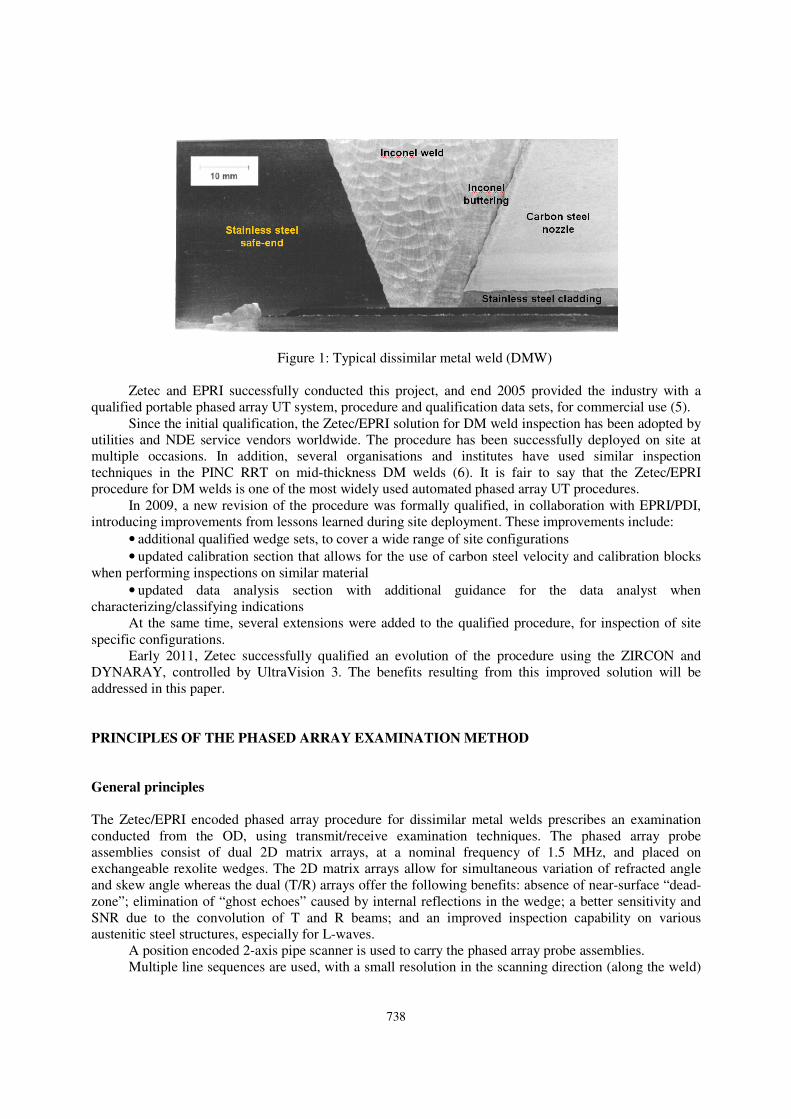
For the detection of circumferential flaws, a dual array assembly is used (see Figure 2). This search unit
allows for transmit/receive (T/R) side-by-side operation with both longitudinal and shear waves. In order
to cover the complete diameter and thickness range, “small” assemblies using 16x2 element matrix arrays
and “large” assemblies using 32x2 element matrix arrays, are used.
Figure 2: Search units for circumferential flaws
The phased array assembly is used to generate focal laws at 45°, 60° and 70° with an adaptable
primary aperture. This “aperture” is then “electronically scanned” in the axial direction to create a set of
linear focal laws.
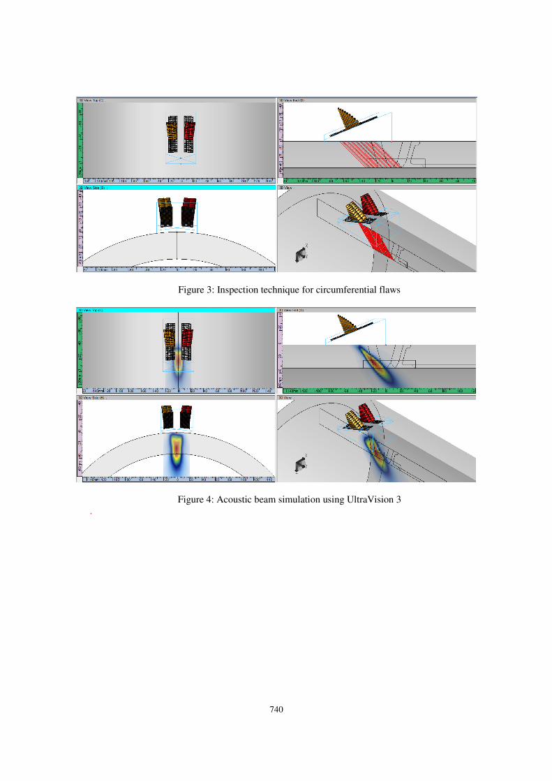
Figure 3Figure 3 shows a schematic representation of this inspection technique (note that only the
45° linear law set is shown). The same wedge can be used to generate longitudinal as well as shear waves.
The search unit design has been theoretically validated for various pipe configurations (see Figure
4), using the 3D acoustic beam simulation module of the UltraVision 3 software.
For circumferential flaw examinations, the ultrasonic beams are oriented perpendicular to the weld.
A multiple-line inspection sequence is used to fully cover the examination volume. The axial positions of
the different scan lines are determined as a function of the pipe thickness, the weld bevel and the access
restrictions of the component.
The considered examination method proved effective for various types of circumferential defects.
Using the advanced features of the UltraVision software, the raw examination data from all focal laws is
volumetrically merged, either angle by angle or all angles together.
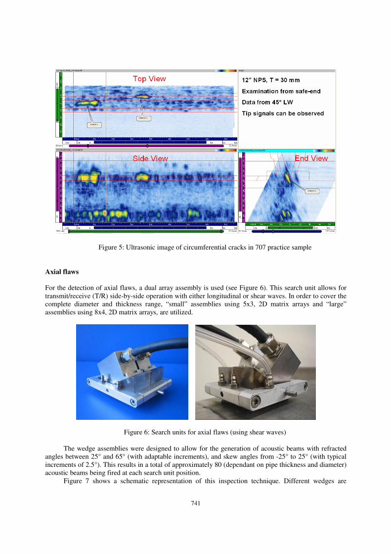
Figure 5Figure 5 shows the ultrasonic images obtained on a 707 practice sample, i.e. a 12”
dissimilar metal weld with a wall thickness of 30 mm. The longitudinal wave beams provide excellent
detection capability with a high signal-to-noise ratio.
740
Figure 3: Inspection technique for circumferential flaws
Figure 4: Acoustic beam simulation using UltraVision 3
.
741
Figure 5: Ultrasonic image of circumferential cracks in 707 practice sample
Axial flaws
For the detection of axial flaws, a dual array assembly is used (see Figure 6). This search unit allows for
transmit/receive (T/R) side-by-side operation with either longitudinal or shear waves. In order to cover the
complete diameter and thickness range, “small” assemblies using 5x3, 2D matrix arrays and “large”
assemblies using 8x4, 2D matrix arrays, are utilized.
Figure 6: Search units for axial flaws (using shear waves)
The wedge assemblies were designed to allow for the generation of acoustic beams with refracted
angles between 25° and 65° (with adaptable increments), and skew angles from -25° to 25° (with typical
increments of 2.5°). This results in a total of approximately 80 (dependant on pipe thickness and diameter)
acoustic beams being fired at each search unit position.
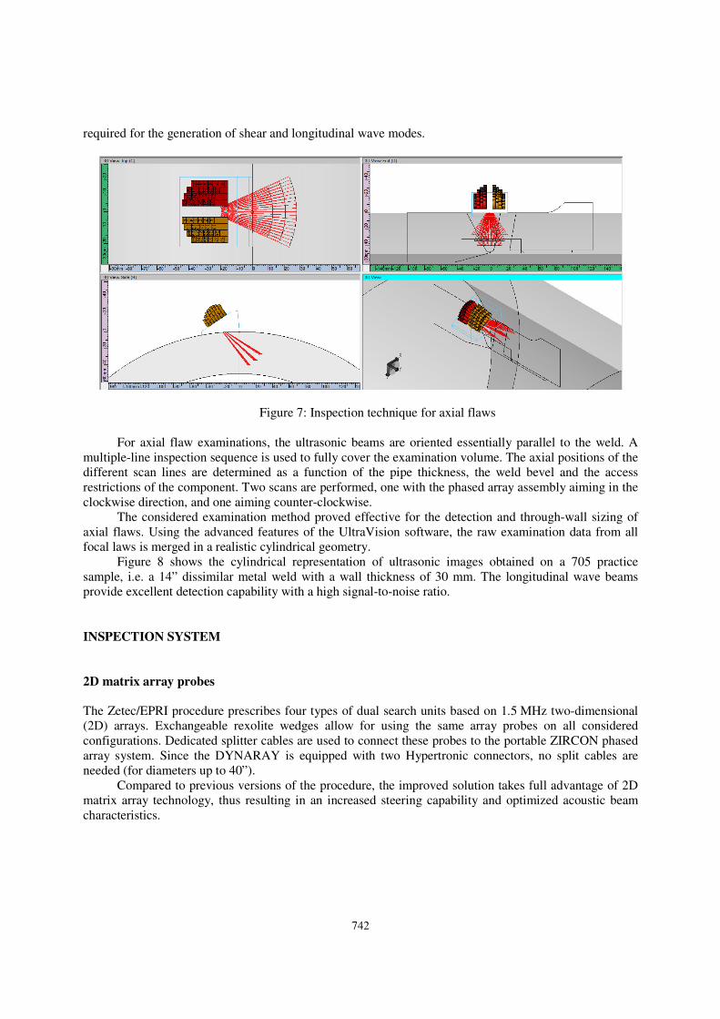
Figure 7 shows a schematic representation of this inspection technique. Different wedges are
742
required for the generation of shear and longitudinal wave modes.
Figure 7: Inspection technique for axial flaws
For axial flaw examinations, the ultrasonic beams are oriented essentially parallel to the weld. A
multiple-line inspection sequence is used to fully cover the examination volume. The axial positions of the
different scan lines are determined as a function of the pipe thickness, the weld bevel and the access
restrictions of the component. Two scans are performed, one with the phased array assembly aiming in the
clockwise direction, and one aiming counter-clockwise.
The considered examination method proved effective for the detection and through-wall sizing of
axial flaws. Using the advanced features of the UltraVision software, the raw examination data from all
focal laws is merged in a realistic cylindrical geometry.
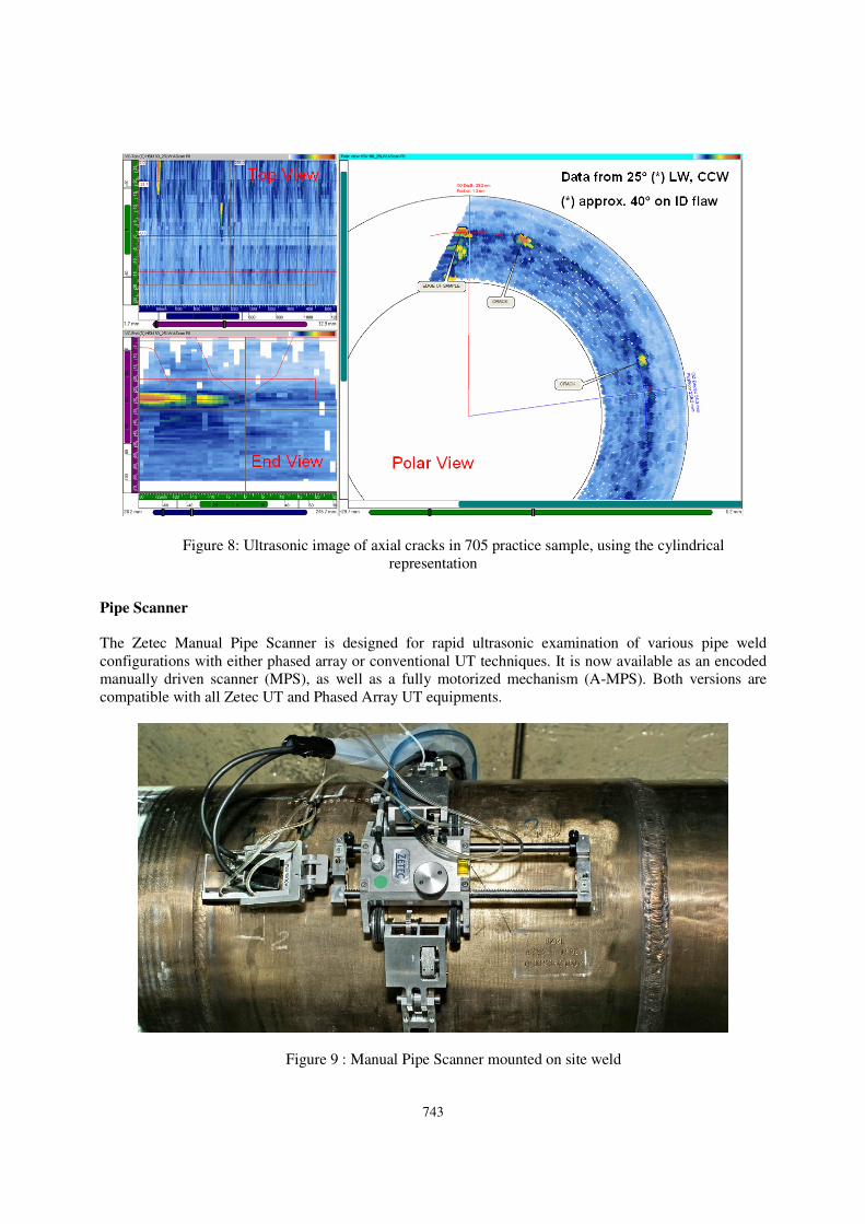
Figure 8 shows the cylindrical representation of ultrasonic images obtained on a 705 practice
sample, i.e. a 14” dissimilar metal weld with a wall thickness of 30 mm. The longitudinal wave beams
provide excellent detection capability with a high signal-to-noise ratio.
INSPECTION SYSTEM
2D matrix array probes
The Zetec/EPRI procedure prescribes four types of dual search units based on 1.5 MHz two-dimensional
(2D) arrays. Exchangeable rexolite wedges allow for using the same array probes on all considered
configurations. Dedicated splitter cables are used to connect these probes to the portable ZIRCON phased
array system. Since the DYNARAY is equipped with two Hypertronic connectors, no split cables are
needed (for diameters up to 40”).
Compared to previous versions of the procedure, the improved solution takes full advantage of 2D
matrix array technology, thus resulting in an increased steering capability and optimized acoustic beam
characteristics.
743
Figure 8: Ultrasonic image of axial cracks in 705 practice sample, using the cylindrical
representation
Pipe Scanner
The Zetec Manual Pipe Scanner is designed for rapid ultrasonic examination of various pipe weld
configurations with either phased array or conventional UT techniques. It is now available as an encoded
manually driven scanner (MPS), as well as a fully motorized mechanism (A-MPS). Both versions are
compatible with all Zetec UT and Phased Array UT equipments.
Figure 9 : Manual Pipe Scanner mounted on site weld
744
The MPS was used to conduct most performance demonstration exercises with the DM weld
procedure, and for multiple site inspections (see Figure 9). The qualified inspection procedure allows for
the use of any manual or automated scanning system, provided that the requirements on the essential
variables for mechanical resolution are satisfied.
Phased array UT equipment
Zetec’s improved solution for encoded phased array UT examination of DM piping welds can be deployed
with two types of new generation phased array UT instruments.
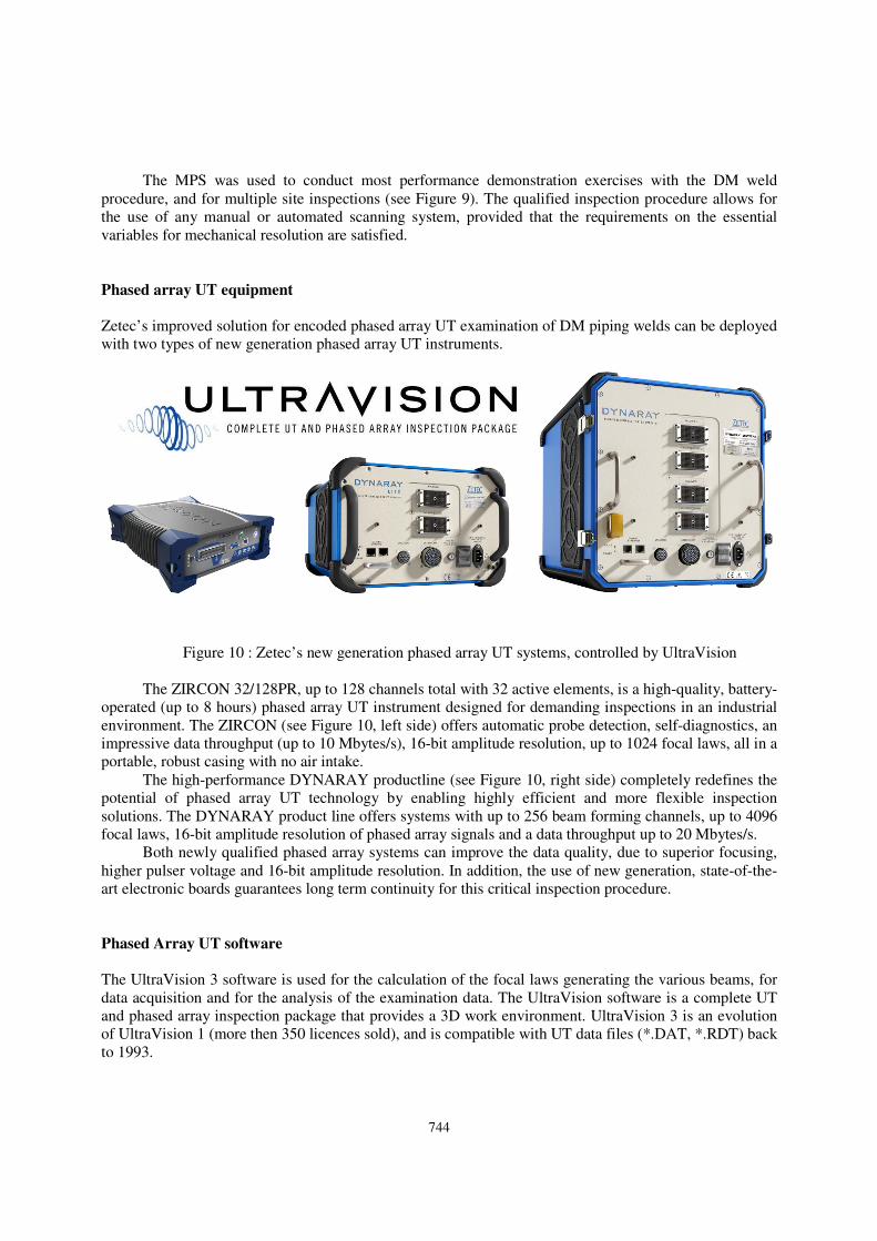
Figure 10 : Zetec’s new generation phased array UT systems, controlled by UltraVision
The ZIRCON 32/128PR, up to 128 channels total with 32 active elements, is a high-quality, battery-
operated (up to 8 hours) phased array UT instrument designed for demanding inspections in an industrial
environment. The ZIRCON (see Figure 10, left side) offers automatic probe detection, self-diagnostics, an
impressive data throughput (up to 10 Mbytes/s), 16-bit amplitude resolution, up to 1024 focal laws, all in a
portable, robust casing with no air intake.
The high-performance DYNARAY productline (see Figure 10, right side) completely redefines the
potential of phased array UT technology by enabling highly efficient and more flexible inspection
solutions. The DYNARAY product line offers systems with up to 256 beam forming channels, up to 4096
focal laws, 16-bit amplitude resolution of phased array signals and a data throughput up to 20 Mbytes/s.
Both newly qualified phased array systems can improve the data quality, due to superior focusing,
higher pulser voltage and 16-bit amplitude resolution. In addition, the use of new generation, state-of-the-
art electronic boards guarantees long term continuity for this critical inspection procedure.
Phased Array UT software
The UltraVision 3 software is used for the calculation of the focal laws generating the various beams, for
data acquisition and for the analysis of the examination data. The UltraVision software is a complete UT
and phased array inspection package that provides a 3D work environment. UltraVision 3 is an evolution
of UltraVision 1 (more then 350 licences sold), and is compatible with UT data files (*.DAT, *.RDT) back
to 1993.
745
Focal law generation
The Advanced Phased Array Calculator, integrated in UltraVision 3, is used to generate the various focal
laws as defined by the examination technique. This powerful software tool supports 1D linear arrays as
well as 2D matrix arrays on flat, cylindrical and custom specimens, in both pulse-echo and transmit-
receive configurations.
Data acquisition
The ZIRCON and DYNARAY systems are set-up and controlled by UltraVision 3 during data acquisition.
Multiple-line scanning sequences are performed that significantly reduce inspection time and offer reliable
detection and sizing of circumferential and axial flaws. The collected data are directly saved to the HDD
of the PC controlling the equipment, thus eliminating laborious and time-consuming file transfer and
conversion. The UltraVision 3 software can handle data files up to 20 GBytes, which allows for an
important reduction of the number of scanning sequences per weld.
Data analysis
The considered examination method requires the use of more than 60 focal laws for circumferential flaws
and more than 80 focal laws for axial flaws. Therefore, the detailed work procedure for data analysis
prescribes the use of the Volumetric Merge tool in UltraVision 3. This tool processes the ultrasonic data
from the individual focal laws to create so-called merged data groups, containing information from all
focal laws in a given data recording or from a subset of focal laws. Thus, the amount of data to be
analyzed is drastically reduced, without affecting the detection capability. The ultrasonic images shown on
the Figures 5 and 8 are based on merged data groups, and clearly illustrate the efficiency of the Volumetric
Merge tool.
In addition, through comparison of ultrasonic responses in various carefully chosen subsets of focal
laws, additional information can be obtained for flaw discrimination and characterisation.
Furthermore, the detailed work procedure for data analysis prescribes the use of the angle-corrected
volumetric projections, overlay of CAD-drawings of the considered weld configurations and the various
other graphical and numerical tools of the UltraVision software.
FORMAL APPENDIX VIII QUALIFICATION
The improved solution for encoded phased array UT examination of dissimilar metal welds was formally
qualified through the Performance Demonstration Initiative (PDI), in May 2011.
The scope of the procedure covers detection, length sizing and through-wall sizing of both
circumferential and axial flaws (no length sizing for axial flaws though), for diameters 1.5” NPS and up,
and a wall thickness range from 5.3 mm (0.210”) to approximately 165.1 mm (6.500”). The procedure is
applicable for smooth weld surfaces where dual or single sided access is available, but the actual
qualification was performed with single sided access (from safe-end side). The examination procedure
does not cover all configurations with tapered weld surfaces, but some site specific configurations have
been adressed.
The qualified procedure addresses the requirements for yearly calibration and on-site checks of
vertical linearity and amplitude control linearity of the phased array system. In addition, detailed
guidelines are given for performing regular active element checks on individual array probes, and
reference settings on the search units.
CONCLUSIONS
From the development and qualification of the Zetec/EPRI phased array UT procedure for DM welds, and
from years of site experience, the following conclusions can be drawn:
1. Dual 2D phased array methodology provides very good inspection capability on both circumferential
and axial flaws in dissimilar metal pipe welds, for a large range of diameters and thicknesses
746
2. Encoded inspections, using either manually driven or fully automated scanning mechanisms, generate
quality inspection data, allowing for reliable detection and accurate length and through-wall sizing
3. New generation phased array UT hardware and advanced software have been developed and formally
qualified, and can improve data quality and inspection efficiency
4. Long term continuity and equivalency of phased array UT hardware and software can now be
guaranteed.
ACKNOWLEDGMENTS
The authors wish to thank Mr. Ronald Swain and Mr. Carl Latiolais from the EPRI NDE Center for their
continuous effort and support during the recent technical justification and qualification phase of this
project.
REFERENCES
1) J. Landrum, C. Latiolais, “Qualification of Dissimilar Metal Weld Inspection in Accordance with
Appendix VIII”, 6th EPRI Piping & Bolting Conference, Point Clear (AL), August 2002
2) “Phased Array Ultrasound Piping Examination Procedure.” EPRI, Palo Alto, CA, 2002, 1006980.
3) “Manual Phased Array UT Techniques for Piping and Dissimilar Metal Pipe Welds.” EPRI, Palo
Alto, CA, 2004, 1008174.
4) “Automated Phased Array UT for Dissimilar Metal Pipe Welds” EPRI, Palo Alto, CA, 2004,
1011054
5) G. Maes, J. Berlanger, J. Landrum, M. Dennis, “Appendix VIII Qualification of Manual Phased
Array UT for Dissimilar Welds”, Combined EPRI 7th Piping & Bolting and 4
th Phased Array
Inspection Conference, Miami Beach (FL), December 2005
6) S. Cumblidge, S.R. Doctor, P.G. Heasler, T.T. Taylor, “Results of the Program for the Inspection of
Nickel Alloy Components”, NUREG/CR-7019, August 2010