Embed Size (px)
Citation preview
JOURNAL OF RESEARCH of the National Bureau of Standards-C. Engineering and Instrumentation Vol. 69C, No.3, July- September 1965
Improved Ten-Picofarad Fused Silica Dielectric Capacitor ! R. D. eu tkosky and L. H. Lee
(Ma rch 8, 1965)
Some defect s in a set of fused silica dielec tric capacitors constructed in 1961 a re lis ted, and m ethods fo r th eir reduct ion or elimination a re described. The con~ tl'uclion of a new set of capacitors com pleted in 1964 is descri bed in deta il. Preliminary sLabi lity data p resented indicate t hlL t the typi cal d ri ft of the H)64 capacitors wi Lh respect to t heir m ean was less Lhan two parts in 107 in five mont hs.
1. Introduction
Capacitor,; u tili ~ ing fused silica as the dielectric have been under investigation at NBS a,nd elsewhere [1] 2 for many years. Early indications were that suitably constructed capacitors of this type would be at least as stable as air ca,pacitors, and addit ionally would be sufficiently rugged to withstand shipment between laboratories.
A set of four fused silica dielectric 10-pF capacitors was constructed at NBS in 1961 [2]. The capacitance elements of th ese capacitors consisted of fused silica disks 7 cm in diameter and 1 cm thiclc Silver electrodes were fired on the two faces of the disks and a third electrod e was fired on the cylindrical smface. The cell in which the element was mounted shielded the face electrodes from each other in t he region external to t h e fused silica element, and was connected electrically to the cylindrical electrode of t he element. The housing contained a fom -terminrtl resistance thermometer for tempen1.ture measurement and was hermetically sealed.
One of the 1961 capacitors was successfully hrtndcarried to se\-eral distant laboratories and retmned. These laboratories included N R C (Crtnada), NPL (England), and N BS Boulder. The largest change in capacitance obser ved upon completion of the round t rip was 0.2 p arts in 106 (ppm). A shipment of this capacitor by commercial carrier was not successful and resulted in a change in its capacitance of 36 ppm. This change was traced t o a sensitivity to severe mechanical shock.
The 1961 capacitors had a number of undesirable features, the shock sensitivity being by far the most impor tant . F mther invest igation indicated that all of the capacitors in the set suffered from this flaw, and that the change in capacitance was caused by motion of the fused silica element in its cell . The element was supported in the cell by means of phosphor bron ze springs which permitted motion of the element along the cell axis. The element could not return to its equilibrium position after displace-
1 T-his work was su pported in par t by the l\1ctrology Engineering Center, Bureau of Nava l Weapons, Pomona, Cali r.
, Figures in b,ackets ind icate the literature references at the en d of t his paper .
ment because of frictional forces between the cylindrical surface of the element and the spring contacts attached to the cell . This mechanism could not have caused a capacitance change if the dir ect electri cal field between the face electrodes had been entirely withill the fused silica. Unfortunately, the direct capacitance included a small con tribution due to fields from the back of a face electrode which enter ed the fused silica element at the insuhttion gap between this face electrode and the cylindrical shield electrode, rtnd terminated at th e opposite face electrode. Motion of the element within its cell rtltered the leakage field and consequently changed the total direct c~1.pacitallce.
A second {law in the 1961 capacitors was ,1. pronounced dependence of capaci tance upon yoltage. I t was necessary to restrict the voltage applied to these c"pacitors to 10 V n n s to reduce the measurement uncertainty f rom t his cause below 0.1 ppm. Since suffLCient sensitivity is ,wailable at this voltage to see one part in 107, the voltage dependence di d not seri ously limit me~,surement accuracy. An inves tigation into the mechanism of the volt age dependence wn,s made, and it was found th '1.t the dependence could be almost eliminated by increasing the thickness of the fU'ed silver electrodes. The evidence indicates that the exis tence of islands of sih-er on the dielectric surface which are not in good electrical contact with the body of the electrode is in some way responsible for the large voltage dependence. A similar effect has been observed in mica capacitors with fired or deposited silver electrodes [3].
Measurements of capacitance and dissipation factor as a function of frequency indicated a capacitance difference from 50 Hz to 20 kHz of about 25 ppm, with a maximum slope and a maximum dissipation factor at about 1600 Hz. The shape of the curve suo'o'ested a relaxation mechanism involving polar imp"'urities in the fused silica. An inves tigation of several optical grades of fused silica disclosed that the use of a grade possessing except ionally good ultraviolet transmission char acteristics r esulted in capacitors with very much smaller frequency dependencies and with dissipation factors not greater than 3 X 10- 6
throughout the audio-frequency region. . Examination of the published optical charactens
tics for the various grades tested disclosed no correla-
773- 721--65----2 173
tion between optical absorption and audio-frequency behavior. It is felt that the presence or absence of the audio-frequency relaxation phenomenon is an accidental result of the technique for producing fused silica. It is possible that changes in manufacturing technique which have no effect on the optical properties of the fused silica may greatly affect the audio-frequency characteristics.
The temperature coefficients of the 1961 capacitors were about 14 ppm;oC. The large values were believed to be the result of a large temperature coefficient of dielectric constant in fused silica. Resist ance thermometers were built into the capacitor housings to eliminate the measurement uncertainties caused by unknown temperatures.
A set of twelve 10-pF fused silica dielectric capacitors was built in 1964. Care was taken to reduce greatly all of the flaws listed abo\Te. The capacitance elements were constructed of type II Suprasil ,3 and were supported in their cells by means of tightly fitting polytetrafluoroethylene (PTFE) rings. Care was taken to keep the gaps between the face electrodes and the cylindrical shield electrode as small as seemed consistent with operation up to 200 V rms. The voltage dependence of each capacitor was measured before final sealing, and the electrodes were replated when necessary. The 1964 capacitors are physically smaller and much lighter than the 1961 capacitors, but were not designed with this as a principal objective.
The construction of these new capacitors is described in some detail to allow their reproduction elsewhere. Some characteristics of the completed set are then presented.
2 . Construction
2 .1. Housing
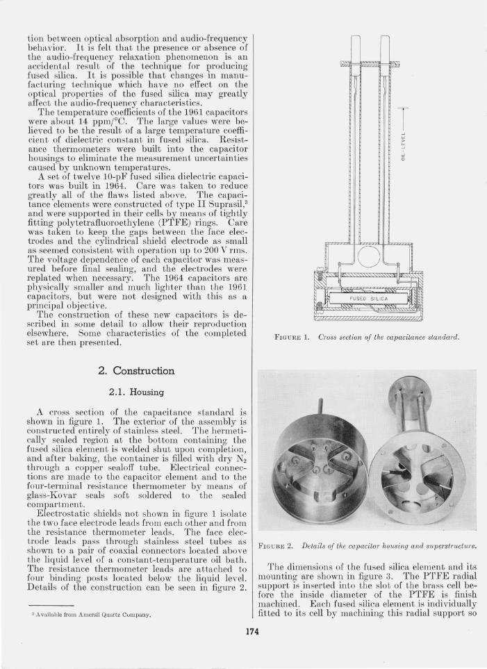
A cross section of the capacitance standard is shown in figure 1. The exterior of the assembly is constructed entu.'ely of stainless s teel. The hermetically sealed region at the bottom containing the fused silica element is welded shut upon completion, and after baking, the container is filled with dry N2 through a copper sealoff tube. Electrical connections are made to the capacitor element and to the four-terminal resistance thermometer by means of glass-Kovar seals soft soldered to the sealed compartment.
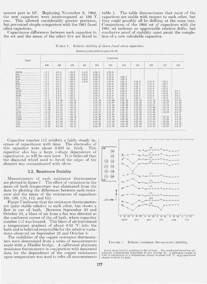
Electrostatic shields not shown in figure 1 isolate the two face electrode leads from each other and from the resistance thermometer leads. The face electrode leads pass through stainless steel tubes as shown to a pair of coaxial connectors located above the liquid level of a constant-temperature oil bath. The resistance thermometer leads are attached to four binding post s located below the liquid level. Details of the construction can be seen in figure 2.
'Available from Amersil Quartz Cumpany.
FIGURE 1.
T ..J W > W ..J
..J
o
~o~ r le~ J€bi~ FUSED SILICA ~ij "'-'
Cross section oj the capacitance standard.
FIGURE 2. Details oj the capacitor housing and superstructure.
The dimensions of the fused silica element and its mounting are shown in figure 3. The PTFE radial support is inserted into the slot of the brass cell before the inside diameter of the PTFE is finish machined. Each fused silica element is individually fitted to its cell by machining this radial support so
174

BRASS CELL
062 015
1 2 4 0
"_L_"~_~02B20_dlom __ 1 j - --2 84 0-diom--
- - -2 938 -d io m-- , ----35 6 2- dlom---'
PTFE RADIAL SUPPORT
rj ====-::::s-': IL-- TO SUIT -- ' I l '25 - --2 850-diom--"
PTFE AXIAL SUP POR T
~L I 125 - ' ;' m '~ 'li -L,42 - I 625- diom - L 020
I 875- diom - ..
OIO-INCH PHOS BRONZE SPRING, I 620-0
FUSED SIL ICA ELE MENT
BRASS COVER r:- 015
- ' L--625- di~m 004
1880-d iom - J ----3562 - diom---
F IGURE 3. Fused silica capacitanceelementand cell di m ensions
F IGU RE 4. P artiall y assembled capacitance element cell .
that the element with its silver electrodes in place can just be removed from the cell with a rubber suction cup. The axial (vertical) constraint on the element is controlled by the use of shims or by machining, so th at an axial interference of about 0.001 in . is obtained. This results in a slight compression of the PTFE axial supports.
Electrical connection s to the face electrodes on the fu sed silica element are made by means of wires soldered to the phosphor bron ze disk springs shown in figure 3. The disks are cu t to the shape of an X and bent as shown in figure 4. Electricttl connection between the cylindricfll electrode and the cell is made by inserting three 0.030-in . ditelll phosphor bron ze wires about 2 in. long into the circular gap between the cell and t he element . The ends of these wires lie in th e slot at the sides o[ the cell with tIle PTFE radial suppor t. The t hree wires are positioned uniformly around t he circumference of the cell and prol'ide three poin ts of electrical conttWL.
2.2. Resistance ThermometEr
The four-terminal thermometer is located on the outside oftlte cell co ntn,ining t he fused silica element , reS shown in figures 1 n,nd 4. The cell is prepared by cementin g a layer of linen cloth over it with shelbc and baking at 100 °C. A length of B & S No . 36 Formvar insulated copper wire with a resis tance o[ 25 Q is doubled over and wound bifil arly over t he linen. .More shellac is t hen applied and baked. Leads to tbe current and potential terminals are co nn ected to t he r esistance wire with soft solder . Tn e junctions are tied down securely and shellcec is appli ed. The co mpleted thermometer is baked for 24 Iu at 75 °C.
2.3. Fused Silica Element
The fused silica element is ground to the dimensions shown in figure 3 with con ventional toolroom grinding equipment. Some care is n ecessary to prevent chipping of the edges. After inspection for chips, the element is cleaned with alcohol, and then with soap and water. It is next immersed in an ultrasonic cleaning bath containing a wetting agent, and rinsed with water. Finally, it is immersed in an ultrasonic cleaning water bath and rinsed with distilled water. After drying at 100 °C, Dupont Silver P aint #4666 is sprayed onto one face and the cylindrical surface, and allowed to air dry . The other face is then sprayed and dried, and the silver is fired onto the element at 480 °C. It is found that single silver deposits thicker than 0.0005 in. are often defective, and that a single application is not sufficient to prevent a dependence of capaci tance upon voltage. A sn, tisfactory remedy is to buff the electrode surface wi th fine steel wool and apply two additional coats of paint to the electrodes. T he preferred final electrode thickness is between 0.0010 and 0.0015 in. T[ the elec trode thickness is increased to 0.002 in. , the large thermal expansion coefficien t of the silver often causes the fused silica element to chip when it is
175

cooled from the firing tempera ture. No noticeable chipping occurs when the silver thickness is less than 0.0015 in.
After the third electrode coat has been fired, the edges of the element are very lightly beveled to separate the cylindrical electrode from the face electrodes. This is done by hand with a diamond wheel and a special jig, using water as a lubricant. CfLre must be taken at this point to avoid making the gap excessively wide and to remove all t races of silver from the beveled por tions of the fused silica. If the diamond wheel is allowed to become contaminated with silver , a thin layer of silver will remain on the fused silica, and a large dependence of capacitance upon voltage will result.
T he element is next fi tted to i ts cell by machining the PTFE radial support. The element is th en baked 24 hr in vacuum at 175°C to eliminate adsorbed wfLter, placed in i ts cell, and the cell is evacuated. The baking and evacuation are essential to produce a small dissipation factor and a stable capfwitfLnce.
After the capacitor has reached room temperature, it is measured fLnd the adjustment necessary to produce e:mctly 10 pF at 25°C is estimated. Using the element and cell dimensions shown in fi gure 3, the capacitance will probably not depart from 10 pF by more than ± 0.05 percen t. An adjustment as smaIl as this can be made quite easily by cu tting a cavity into either a face or the cylindrical surface of the element with a small diamond wheel. The cavity is then spr ayed with silver paint and refired. The adjustment sensiti \lity depends upon the diamond wheel diameter and thickness, the depth of cut, and the position of the cavity on the element. A jig may be readily set up to regulate dep th of cut, and a calibration of capacitance change versus dep th of cut measured with a trial element. Usually two or three successive adjustments suffice to produce a capacitance of 10 pF ± 50 ppm. A typical fused silica element after adjustment is shown in figure 5.
After final adjustment, a test is made for voltage dependence, and if necessary, the en tire elemen t is replated. The stainless steel housing is then welded shut, and the sys tem is bak:ed at 65°C with a vacuum pump attached to the sealoff tube. After cooling,
FIGURE 5. Com pleted fused silica element with an adjustment of minus 50 ppm.
the housing is filled wi th dry N2 at atmospheric pressure, and the sealoff tube is pinched off and soldered. A series of temperature cyclings is made between 50 \ and 0 °0, and the unit is placed in to operation. Figure 6 shows a completed capacitor.
3. Performance
3 .1. Capacita nce Stability
All measurements of capacitance stfLbility reported here were made at 1592 H z using a 10 :1 bridge, wi th all capacitors in an oil bath maintained at 25.0 °C. The measurements seemed to indicate that these capacitors were at least fLS stable as any other capacitors in our laboratory. Accordingly, the mean of five of these capacitors, numbers 108, 109, 1l0, 112, and 113 was taken to be the basis for the comparisons. No temperature corrections were applied since the capacitors were at nearly the same temperature and had nearly identical temperature coefficien ts. The application of individual corrections for temperature sligh tly r educes the scatter in the measurement series repor ted below. Ini tially, all measurements were made wit h 10 V rms applied to the capacitors to allow ready comparison with the 1961 set of capacitors which h ad large voltage dependencies. Bridge readings wer e recorded under these conditions to the
F IGURE 6. Completed capacitance standard.
176
nearest part in 107• Beginning November 9, 1964, the new capacitors were intercompared at 100 V
' rms. This allowed considerably greater precision, but prevented simple comparison with the 1961 fused silica capacitors.
Capacitance differences between each capacitor in the set and the mean of the select five are listed in
table 1. The table demonstrates that most of the capacitors are stable with respect to each other, bu t they could possibly all be drifting at the same rate. Comparisons of the 1964 se t of capacitors with the 1961 set indicate no appreciable relative drifts, but conclusive proof of stability must await the completion of fl, new calculable capfl,citor.
T A BLE 1. Relative stabilit y oj eleven Jllsed silica capacito1"s
Decimal points indi cate parts in 10".
Date
108 109 110 111 ll2
8/4/6L ............ . . . -2. 5 +1.6 -28.3 +5.0 +18.2 8/4 . .. .............. . -2.5 +1.6 - 28.3 +5.0 + 18. 2 8/17 . ....•.. . ..... . . -2. 5 +1.5 -28.3 +5. 0 +18.3 8/26 .... ..... . . . .. . . . -2. 5 +1.5 -28.3 +4.9 +IR.2 9/8 ... ............... -2.6 + 1. 6 -28.2 +5. 0 +18.2 9/1L ....... ... ...•. . -2.6 + 1. ., -28.2 + 18.2 9/22 ...... .. . . ...... . -2.6 + 1. 5 -28.2 +1~.2 10/5 •.. . . . ...... . ...• -2.6 + 1. 5 -28. 2 + 18.2 10/20 .... .....•...... -2.5 +1.6 -28. 2 + 18.2 10/22 ... ... ......... ' -2. 5 + 1.6 -28. 2 +18.2 10/30 .....•.. ..... .. . -2 .. \ + 1.6 -28. 1 +18.2 11 /5 ........• . . •.•... -2.5 + 1. 5 -28. 2 + 18. 2 11 /9 ........... . . .... -2.57 + l. 58 -28. 18 + 18. 19 11 /16 ...... ...... .... -2.53 + 1. 57 -28.18 +18.18 11/24 ..... ........... -2.53 +1.54 -28. 15 +18. 10 11 /30 ... ...••...... •• -2.58 +1.55 -28. 13 +18. 11 12/7 .... . . .... . ...... -2.59 + 1. 56 -28. 13 +18.12 121l4 ......•... .. .... -2.62 + 1. 56 -28. 12 +18.12 12/21. ..... ....... . . . -2.52 + 1. 05 -28. 15 + 18.08 12/28 .... . ........... -2.56 + 1. 55 -28. 14 + 18.09 1/4/65 .... . .. . . . . .. . . -2.51 + 1. 54 -28.15 + 18.08 1/12 ... . .. . .... . . . . . . -2.50 + 1. 54 -28. 15 + 18.07 1/19 ........... . . .. . . -2.50 + 1. 54 -28. 15 + 18.06 1/26 ...... ... . . ... . .. -2.50 + 1. 54 -28. 15 + 18.07
Capacitor number 117 exhibits a fairly steady increase of capacitance with time. The electrodes of this capacitor were about 0.002 in. thiclc This capacitor also has a large voltage dependence of capacitance, as will be seen later. It is believed that the diamond wheel used to bevel the edges of the element was contaminated with silver.
3.2. Resistance Stability
Measurements of each resistance thermometer are plotted in figme 7. The effect of variations in the mean oil bath temperatme was eliminated from the data by plotting the differences between each resistance and the mean of the resistances of capacitors 108, 109, 110, 112, and 113.
FigUI'e 7 indicates that the resistance thermometers are quite stable relative to each other, but shows a flaw in OUI' oil bath. Between September 20 and October 10, a blast of air from a fan was directed at the southwest corner of the oil bath, where capacitor number 115 was located. This blast of air introduced a temperatme gradient of about 0.02 °C into the bath and is believed responsible for the relative variations observed on September 22 and October 5.
The stabilities of the copper resistance thermometers were determined from a series of measm'ements made with a Mueller bridge. A calibrated platinum resistance thermometer in conj unction with measUI'ed data for the dependence of the copper resistances upon temperatm'e was used to refer all measm'ements
Capacitor
113 114 ll5 116 117 118
+ 10.8 + 10.9 + 10.9 +31.5 + 10.9 +31. 5 +10.9 +3 l. 5 +21. 6 +15.6 -23.2 + 10.9 +31. 6 +21.4 +15.5 -23.1 + 10. 9 +31. 5 +2 l.4 + 15. 6 -23.1 + 10.9 +3 l. 5 +2 1. 5 + 15. 6 -23.0 +11 . 0 +31.6 +21.6 + 15.8 -22.9 +6.1 + 11.0 +31.5 +21.6 + 15.8 -22.9 +6.1 + 11.0 +31.5 +21. 6 + 15.8 -22.9 +6.1 + 10.9 +31. 5 +21. 5 + 11;.7 -22. 9 +6. 1 + 10.98 +31.49 +21.59 + 15.76 -22.85 +6.23 +10.97 +31.46 +21.59 + 1.5.73 -22.87 +6.20 +11.04 +31.38 +21.60 + 15.67 -22.76 +6.22 + 11.06 +31.40 +21.62 + 10.69 -22. i3 +6.26 + 1l.05 +31.41 +21. 60 + 15.68 -22.74 +6.24 + 11. 07 +31.41 +2 l. 59 + 15.68 -22.69 +6.27 + 11.04 +3 1. 3, +21. 60 +15.66 +6. 21 + 11. 06 +31.37 +2 1.56 +15.64 -22.70 +6. 21 +11. 04 +31.36 +21.54 +V;. 64 -22.69 +6.20 + U .04 +31. 36 +21. 56 +15.65 -22.68 +6.21 + 11.04 +31. 36 +21. 56 + 15.65 -22.68 +619 + 11. 04 +31.37 +2 l. 56 +15.65 -22.67 +6.21
NW 118
@) ~ 117
@ 116
@ @) 11 5
@ @ @ @
114
@ @ SW 113
112
.001 OHM J 110
109
5 15 25 5 15 5 5 15 25 5 15 25 5 15 25 5 r 5 25
SEPT. OC T. NOV. DEC. JAN. FEB.
FIGU RE 7. R elative resistance thermo meter stability.
In sert shows-relative positions in the oil ba th. The southwesCcorner' was abo normally cold,between Septem ber 20 and October ]0. A resistance change of 0.001 Il corresponds to a temperature change of about 0.01 °0, or~a::,capacitance change of about 0.1 ppm.
177
to a standard temperature. The limited information currently av ailable indicates that the mean of the five selected resistances at a constant temperature has not changed more than 0.0001 Q in 2 months . This corresponds to about 0.001 °C; or, referred to a capacitance correction, about 0.01 ppm.
3.3. Temperature Coefficients
The temperatures of the capacitance standards may be measured by means of the internal 25-Q resistance thermometers. The capacitances at a specific temperature may then be determined if the capacitance temperature coefficients are known.
In practice, the temperature is usually treated as an implicit variable. A report of capacitance calibration then contains values for the capacitance and for the thermometer resistance at a temperature near 25°C. A later measurement yielding a different thermometer resistance is corrected to the standard resistance thermometer value by reference to a plot of capacitance versus resistance for the standard.
NIeasurements of the capacitance-resistance function have been made over the temperature range 20°C to 30 °C. The curves deviate from a straight line by about 2 ppm at the extremes and are all concave upwards . The slopes at 25°C range from 100.4 ppm/ Q to 110.0 ppm/ Q. The actual capacitance temperature coefficients are about 10 ppm;oC which is substantially smaller than the 14 ppm;oC temperature coefficients of the 1961 fused silica capacitors. No explanation for this difference has been found.
3.4. Hysteresis
The capacitances of most air or solid dielectric standards at a given temperature depend upon the previous temperatures to which the standards have been subjected. Table 2 shows the magnitude of this hysteresis effect in the 1964 set of capacitors. Prior to September 8 all of the capacitors were subjected to a temperature of 50°C, and then replaced in the oil bath at 25 °C. On September 8, their capacitances were measured with respect to a capacitor maintained at 25°C throughout the experiment. Following these measurements, the capacitors were cooled to 0 °C, and then placed back into the oil bath. They were measured a second time on September 9. Table 2 shows that the capacitances increased an average of 0.28 ppm following the 0 °C treatment. A second subjection to 50°C and a return to 25 °C resulted in the September 11 data in table 2. The capacitances returned most of the way to their original September 8 values, but an average capacitance increase of 0.06 ppm remained. Since the data were only recorded to the nearest part in 107, this overall change may not be real. The effect illustrated by table 2 represents one of t he most serious faults in the capacitors, and one for which the mechanism is not completely understood. It is believed that the large differential expansion coefficient between the fused silica element and the silver electrodes may be partially responsible.
T ABLE 2. Dependence of capacitance u pon prior thermal hist01'Y
September 8 and September 11 data were taken a t 25 °C after subjection to 50 °C ; I September 9 data were taken at 25 °C after subj ection to 0 °C (see text ). Capacitance differences from t he September 8 data are given in parts per million.
Capacitor September 8 September 9 Sep tember 11
lOS 0 +0.15 + 0. 1 109 0 + .35 . 0 110 0 +. 45 +. 1 112 0 +. 35 +. 1 113 0 +.25 +. 1 114 0 + . 25 +. 1 115 0 + .35 - . 1 116 0 + . 35 . 0 117 0 +. 05 +. 1
Mean change . . __ __ ________ . +.28 + .06
3.5. Voltage Dependence
Some techniques and apparatus were developed recently at NBS for measuring the dependence of 100 and 1000 pF capacitors upon voltage, with uncertainties in the order of 1 part in 109 [4]. The equipment was used for measuring the voltage dependencies of the 10 pF capacitors with slightly I
larger uncertainties. Table 3 shows the capacitance differences observed when the voltage was changed from 100 V to 200 V. The computed probable error of the data in table 3 is 6 parts in 1010, and the systematic e1'1'or is estimated to be less than 2 parts in 109• Since the voltage dependence of a standard depends upon which electrode is at ground potential, all of the standards are marked with a "D" near the coaxial connector chosen for the ground potential lead.
T A BLE 3. Dependence of capacitance and dissipation f actor u pon vol/age
T he increases b capacitall ce find dissipation factor due to increasing the voltage from 100 V to 200 V rms at 1592 Hz at e shown.
Cap~cito r tiC l1G C we
108 + 1. 3XlO-' - 3.4XIo-' lun -3.6 -2.2 110 -5. 2 + 1.2 112 -5. 0 -4.6 113 -2. 6 +0.6 114 - 1.0 + 1. 0 11 5 +4. S - 0. 1 116 - 1. S - .3 117 + 12.4 - 2. 2 118 +9.S -1. 4
3.6. Frequency Dependence and Dissipation Factor
The result of comparing the fused silica capacitors with two 10 pF air capacitors at three frequencies is reported in table 4. Capacitor A was constructed with concentric cylinch'ical electrodes, and capacitor B with rigid parallel plates. Identical results were obtained at 159 Hz, using the two capacitors, but a significant difference was observed at 15900 Hz. The cause of the discrepancy is not known, but probably involves either mechanical resonances or excessive series inductances in one or both of the
178
air capacitors. The measurements at 159 Hz were extremely difficult to make due to poor bridge sensitivity. The computed probable error of the 159 Hz data in table 4 is 2X 10- 7•
T ABLE 4. F requen cy dependence of the fused silica capacitors j'elative to two air capacit01's (see text)
Capacit.or 159 Hz 1592 liz 15900 lIz A 15900 lIz n
ppm ppm ppm 10~ +1.3 0 -O.G -1.9 109 +1.0 0 -. 2 -1.'> 110 +1.8 0 -.8 -2.1 112 +0.2 0 +.2 -1.1 113 + 1.9 0 -.9 -2.2 114 +0.1 0 +.2 -2. 1 115 +1.2 0 -.R -3.1 116 -r0.3 0 -.3 - 2.6 117 +l.fi 0 -1.2 -3.5 118 +1.8 0 -0.6 -1.9
Accurate measurements of dissipation factor cannot be made fLt NBS at this time. Comparisons of the fused silica dielectric capacitors with sever al types of flir capacitors suggest that the dissipation factors of the fused silica capacitors are probably between 0 and + 3 X l 0- 6 at 1592 Hz.
3.7. Shock Sensitivity
The capacitors were tested upon completion for shock sensitivity by dropping them onto a hardwood table. Various angles of impact and various heights up to 8 in. were tried. The largest capacitance change observed was 1 part in 107 which occUl'red when a capacitor fell about 8 in. in an upright position. Falls through smaller distances usually produced no observable change in capacitance.
3 .8 . Transportation Experiences
A fused silica dielectric capacitor designated number 107 and which was identical with those described in this paper was shipped to the National Research Council of Canada (NRC) on July 28, 1964, via air parcel post. Prior to shipment, it was compared with capacitor number 108. Number 108 was hand-
carried to NRC and retUl'ned between August 4 and August 17, 1964, and again between December 8 and December 11, 1964. Comparisons of the two capfLcitors at NRC indicated no relative change in the two capacitances larger than 0.2 ppm; and as can be seen from table 1, no change in number 108 occUl'red during either of the two round trips.
4. Conclusion
Much more data is needed to evaluate conclusively the reliability of the 1964 set of fused silica dielectric capacitors. Existing evidence suggests that stabilit ies in the order of a few parts in 107 may be expected, and that the capacitors can probably withstand normal handling during shipment between laboratories.
Some further modifications of the design may result in an improved standard. A study of the mechanism which produces the capacitance hysteresis effect with large temperature changes would be of value, and consideration might be given to improving the support system for the fused silica element.
It is felt that the choice of 10 pF for a fused silica dielectric capfLcitor results in a design of nearly optimum stability. Other values would be u eful as secondary standards and should not be difficult to construct.
5. References
[1] M. Kanno, Researches on standard capacitors, researches of the eleetl'otechn ical laboratory (Japan) , No. 597, Apl'il1961 (in Japanese).
[2] R. D. Cutkosky and L. I-I. Lee, The construction and behavior of a transpo rtable ten picofarad capacitor , comite consulatif d 'electl'icite, Aupres Du "Co mite In tel'l1ational Des Poids et Mesmes, " 10 Session 1963, p.44.
[3] Standard capacitors and the ir accuracy in practice, Notes on .Applied Science 13, (NPL) 19.55.
[4] J. Q. Shields, The voltage dependence of precision air capacitors, to be published.
(Paper 69C3-196)
179


![Low scatter and ultra-low re ectivity measured in a fused ... · detector’s primary optics are made of fused silica substrates with ion-beam-sputtered dielectric coat-ings [3] to](https://img.pdfslide.net/doc/110x75/5ed53837606e340b7a35e759/low-scatter-and-ultra-low-re-ectivity-measured-in-a-fused-detectoras-primary.jpg)