Embed Size (px)
Citation preview
Asian Journal of Engineering and Applied Technology ISSN: 2249-068X Vol. 4 No. 1, 2015, pp.30-38
© The Research Publication, www.trp.org.in
Improvement in Thermal Efficiency of a CI Engine Using a Waste Heat Recovery Technique
Aashish Sharma1, Ajay Chauhan1, Himanshu Nautiyal2, Varun3 and Pushpendra Kumar Sharma2
1Lovely Professional University, Phagwara, Punjab, India 2THDC Institute of Hydropower Engineering & Technology, Tehri, Uttarakhand, India
3National Institute of Technology, Hamirpur, (HP) India E-mail: [email protected], [email protected]
Abstract - A big portion of the heat supplied to an internal combustion (IC) engine is not converted into work and wasted through the exhaust gases in surroundings. If this heat is recovered or used by some means then improvement can be obtained in engine’s overall efficiency. In the present work, an experimental work is carried out to study the effect of waste heat recovery of exhaust gas in a Compression Ignition (CI) engine. The results show that considerable reduction in engine fuel consumption can be obtained with the help of exhaust heat recovery through a heat exchanger. A significant amount of heat of exhaust gases can be recovered by vaporization of fuel using a heat exchanger. Keywords: Engine; Efficiency; Ignition; Heat; Recovery
I. INTRODUCTION
Energy has become an indicator of economic growth and social development of a country. Generally human consume the energy from fossil fuels and use this energy in various sectors of domestic and industrial activities as well as for their comfort. Almost all developing and developed countries in the world are dependent on fossil fuels to obtain energy but their contribution in problem of climate change has become a matter of great concern. Today the entire world is focusing on the proper and best use of fossil fuels so that the environmental problems associated with them can be reduced considerably. This has become a great interest for scientists and engineers to find out the suitable alternatives for using efficient use of fossil fuels and recovering heat so that wasted heat can be reduced. IC engines have become an integral part of all human and commercial activities in daily life and widely used in power generation, transportation and agricultural sectors. But today the need of demand reduction and low harmful emissions through the efficient engines is being increased. Advance technology has the major interest in recent years particularly in highly efficient IC engine. The IC engines have several applications and are commonly used in cars, aircrafts and boats etc [1]. But the problem of fuel crises due to their fast depletion nature, environmental impediments associated with them are putting a question mark in the using of IC engines in future. Therefore, it is important to think about the improvement of efficiency of IC engines.
IC engines transform about 25% to 35% chemical energy into mechanical work. About 70% of total energy is wasted through exhaust gas, coolant and radiation [2]. Exhaust gas temperature is high due to combustion process inside the cylinder, which cause cylinder wall temperature get high and proper cooling is required to minimize the cylinder wall temperature. Several industrial activities and processes in various sectors requires considerable amount of heat energy which generally not utilized efficiently. The wasted heat energy from the industries is transferred into the surroundings in the form of unburned fuels, sensible heat discharge from drain water and through sensible and latent heat through exhaust gases discharge. If this wasted energy is recovered by some means, better results in the performance of engine can be obtained. So, there is a big scope to recover wasted heat energy from IC engine and use it in some other applications. The wasted heat energy can be recovered efficiently through the combustion equipment to utilize wasted fuel and through heat recovery equipment to reuse sensible and latent heat through exhaust gases. Several efforts have been expended to reuse the wasted heat during past decades. This work describes the utilization of waste heat which is coming through exhaust gas and the engine performance.
II. LITERATURE REVIEW Waste energy from engine is normally a byproduct which is in form of heat. Energy is lost from the IC engine to the environment in the form of exhaust gas, cooling water, lubrication oil and radiation. Generally waste heat recovery is a technique, which enhance the performance of engine and can reduce the brake specific fuel consumption (bsfc) and consequently thermal efficiency is improved. Tahani et al. [3] showed the waste heat recovery from 12 lt. CI engine using organic Rankine cycle. In the study, two different configuration of organic Rankine cycle (ORC) for waste heat recovery from exhaust gas and coolant: preheat configuration and two stage configuration. An optimized result was given at different working fluids R-134a, R-123 and R-245fa. The power generation and cycle thermal efficiency were maximized. Finally it was found that R-123 is the best working fluid which gave best performance and increase thermal efficiency by 11.73% and 13.56 % respectively in both configurations. It was also observed that preheating configuration has better result if R-134a is
30AJEAT Vol. 4 No. 1, Jan - June 2015
used as working fluid in both configuration but preheat configuration was not sufficient to recover total heat due to mass flow rate limitation.
Alberto Boretti [2] showed optimum speed power turbine to recover the exhaust heat of CI diesel and gas engine. This was done by using turbocharger and intercooler and improvement was shown in fuel conversion efficiency at optimum speed. The exhaust energy is recovered by the power turbine that operates at optimum speed. A by-pass and continuously variable transmission (CVT) link is used to crankshaft. Gear ratio between power turbine and crankshaft is replaced by CVT. Due to this advantage power turbine decoupled from the speed of crank shaft.
Chauhan [4] presented a review on recovery of waste heat in IC engine. The study discussed six technologies to recover the waste heat which has come from the exhaust gas of IC engines viz. turboelectric generator technique, organic Rankine cycle technique, six stroke cycle technique, new development in turbocharger technique and combination of these techniques. These techniques have some merits and demerits, but useful to recover waste heat from exhaust.
Bibin et al. [1] carried out a study on waste heat recovery in a hybrid engine with supplementary combustion chamber. In this study waste heat was utilized by producing the electrical energy with the help of turbocharger. The waste heat is utilized to burn the additional amount of the fuel. The thermoelectric generator which was used in produces electrical energy. Finally energy was recovered by the combination of compressor and alternator that was coupled with the turbine.
Kumar et al. [5] studied a waste heat recovery in IC engine using thermos-electric technology. In the study a heat exchanger and 18 thermoelectric generator modules were designed and tested in test rig and overall efficiency of an engine was improved by using waste heat. Thermoelectric module was used as a generator which was a solid state device that converts thermal energy into electrical energy from a temperature gradient. Its principle was based on Seebeck effect. Thermoelectric modules were selected on the basis of temperature differences between exhaust side and engine coolant side.
Rashad et al. [6] studied a single cylinder diesel engine performance under recycling and conditioning of exhaust for air intake. In the study a single cylinder air cooled engine having 8.3 HP and running at 1500 rpm was tested at test rig for measuring parameters. The engine was operated in different conditions viz. increase O2 percentage in an open mode up to 30% and increase CO2 in inlet charge for close mode operation. The results showed that inlet charge leads to increase the rated brake power with increasing O2
percentage and decreases fuel consumption and increase brake mean effective pressure. CO2 presence in inlet charge show harmful effect on engine performance. A theoretical model was also presented to predict overall performance.
III. EXPERIMENTATION
After the combustion process in IC engines, efficiency of engine is low due to high amount of heat losses. This heat loss is either by the exhaust gas or coolant. So there are various parameters that affect the thermal efficiency and bsfc of the engine. Direct injection and indirect injection are the injection methods that affect the performance of a CI engine. Many assumptions and operating factor affect the performance of the engine.
a. Compression ratio: mechanical efficiency reduceson increasing the compression ratio due to increasein weight of reciprocating parts.
b. Engine speed: on increasing the engine speed, lossof the heat during compression decreases.
c. Engine output: with an increase in engine outputthe air fuel ratio decreases.
d. Injection timing: for higher ignition advancepressure and temperature at the beginning ofinjection are lower.
e. Quality of the fuel: lower self-ignition temperaturemust be use for better performance.
f. Intake temperature: on increasing the intaketemperature, compressed air temperature increasecauses delay period reduces.
g. Intake pressure: on increasing the intake pressurereduces the auto ignition temperature.
So assumptions are based on these factors that can increase the performance of engine. The objective of the present work is to study the recovery of waste heat exhaust gas by vaporization of fuel through a small heat exchanger. An amount of fuel is vaporized by the self-made heat exchanger. Copper tube is use in heat exchanger for the heat recovery and flow is parallel flow in the shell and tube heat exchanger.
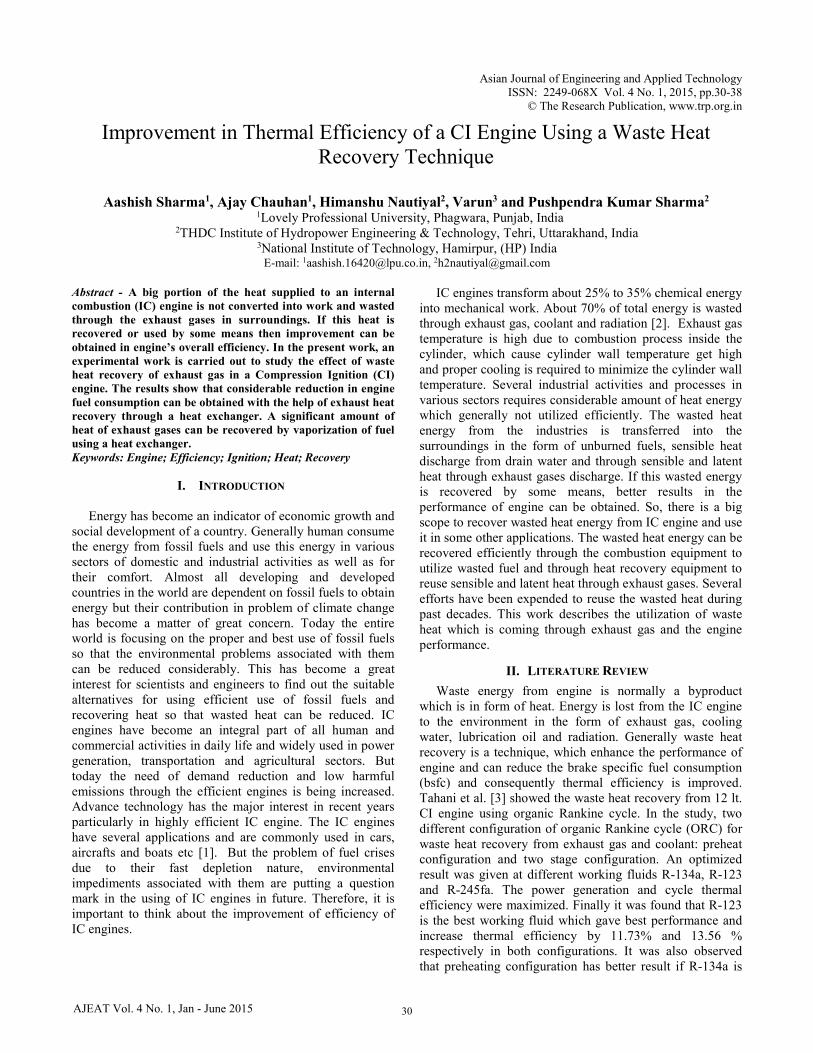
The experiment is conducted on modified single cylinder water cooled engine that runs at 1500 rpm having 5.2 kW power. The experimental setup is shown in Fig 1 and test rig specification is given in Table 1. To conduct the experiment, firstly a heat exchanger is selected for waste heat recovery. The diameter of the heat exchanger is optimized and other parameters viz. length and thickness of heat exchanger are found out. Copper pipes are used inside the heat exchanger of length 2000 mm.
31
Improvement in Thermal Efficiency of a CI Engine Using a Waste Heat Recovery Technique
AJEAT Vol. 4 No. 1, Jan - June 2015
Fig 1: Schematic of experimental setup
TABLE I ENGINE SPECIFICATIONS
Manufacture Kirloskar Oil Engine Ltd., Pune Engine Single Cylinder. 4-Stroke,
water cooled diesel engine Bore 87.5 mm Stroke 110 mm Comp. Ratio 17.5 Capacity 661cc (0.661 Ltrs) Power 5.2 kW at 1500 rpm Sp. Fuel Combustion 220 gms/kW-hr (0.22kg/kW-hr) RPM 1500 rpm BHP@1500 rpm 5.2 kW Cooling System Water Cooled
Experiment is done on the test rig. The engine which is used in this experiment is run on dual mode: one without diesel vapor mixture and another with diesel vapor mixture. Firstly all readings without diesel vapor mixture are measured. The supply valve of water for engine is open first. Now fuel supply is started and time taken is measured with the help of digital stop watch for the fuel consumption. The first load is set and first reading of exhaust temp at 27° crank angle injection timing on computer through the thermocouple noted down. Time is taken for the first 20 cc of fuel. This procedure continues for next load and found all reading for exhaust gas temperature without diesel vapor mixture at 27° crank angle injection timing. Similarly all procedure is continued at 30° crank angle injection timing and 27° crank angle injection timing with direct port supply (DPS).
Now experiment testing is done with the diesel vapor fuel mixture. A heat exchanger is used to this process. A constant supply of exhaust gas is used through the differential valve. Only 4 % of exhaust gas is used in this process. Now the fuel supply is started to the heat exchanger this fuel is vaporized by the heat exchanger. Again time taken is measured with the help of stop watch. Now diesel vapor mixture is used in intake system which is supplied by the accumulator. Again the loads are set and measured all reading at 27° crank angle injection timing. Similarly all readings are measured at 30° crank angle injection timing and 27° crank angle injection timing with DPS.
A heat exchanger-accumulator mechanism is used to vaporize the fuel and catalytic cracking. Accumulator has
T1: Exhaust gas temp. T2: vaporized fuel temperature after HE. F1: fuel flow DP (differential pressure) unit F2: air intake DP unit PT: Pressure Transducer N: RPM Decoder
Pre-chamber
Accumulator
Heat Exchanger
Fu-el
Water
Rotameter
Control Panel
Engine
Dynamo
meter N
T2
T1 PT
F1
F2
32
Aashish Sharma, Ajay Chauhan, Himanshu Nautiyal, Varun and Pushpendra Kumar Sharma
AJEAT Vol. 4 No. 1, Jan - June 2015
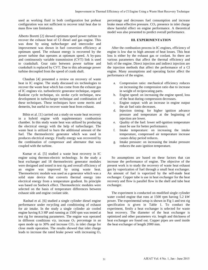
20 mm inner shell diameter and 50 mm of outer shell diameter. Accumulator is mounted on intake manifold to supply the diesel fuel in vapor form and it is mixed with air
into intake system. Fig 2 shows the schematic of heat exchanger and its specifications are presented in Table II.
Fig 2: Schematic of heat exchanger
TABLE II SPECIFICATIONS OF HEAT EXCHANGER
S. No.
Particular Dimension (mm)
1 Diameter 420 2 Length 280 3 Thickness of the cylinder 2 4 Diameter of the copper pipe 12 5 Length of the copper pipe 2000
IV. DATA ANALYSIS
The engine is tested at different loads from 5 kg to 30 kg at different time intervals, by connecting a thermocouple at the engine’s exhaust. Heat loss through the exhaust gas from internal combustion is calculated as follows. The following data were assumed for the study [7]
a. Volumetric efficiency is 0.8 to 0.9b. Density of diesel fuel is 0.71 to 0.85 gm/ccc. Calorific value of diesel is 42 to 45 MJ/kgd. Density of vapor fuel is 1.167 kg/m3
e. Specific heat of exhaust gas is 1.1-1.25 KJ/kg °KExhaust heat loss through diesel engine: Compression ratio (r):
r = (Vc+Vs) / Vc Vc = 4 × 10 -5 m3
Total volume (Vt) = Vc + Vs =7.01 × 10⁻⁴ m3 Mass flow rate of fuel (on the basis of specific fuel consumption) ṁf s.f.c = ṁf / powerṁf = 0.3177 gms/secVolume rate = swept volume × speedVolume rate (V) = Vs × N
= 8.262 × 10⁻³ m3/ sec Volumetric efficiency (ηv)
ηv = volume of air/ swept volume ηv = ṁa / ρa × n × Vs ṁa = ηv × ρa × n × Vs = 8.625 gm/sec
Diesel in
Diesel out
Exhaust Gas in
Exhaust Gas out
33
Improvement in Thermal Efficiency of a CI Engine Using a Waste Heat Recovery Technique
AJEAT Vol. 4 No. 1, Jan - June 2015
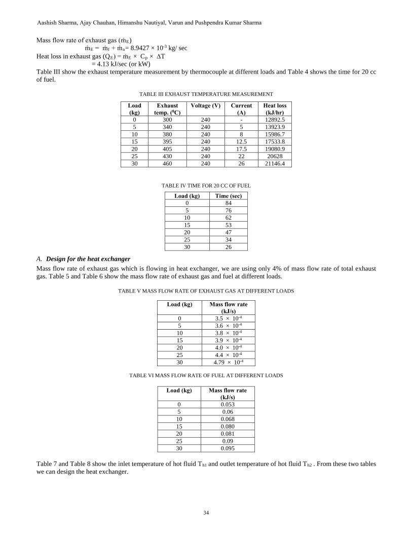
Mass flow rate of exhaust gas (ṁE) ṁE = ṁf + ṁa= 8.9427 × 10⁻³ kg/ sec
Heat loss in exhaust gas (QE) = ṁE × Cp × ∆T = 4.13 kJ/sec (or kW)
Table III show the exhaust temperature measurement by thermocouple at different loads and Table 4 shows the time for 20 cc of fuel.
TABLE III EXHAUST TEMPERATURE MEASUREMENT
TABLE IV TIME FOR 20 CC OF FUEL
Load (kg) Time (sec) 0 84 5 76
10 62 15 53 20 47 25 34 30 26
A. Design for the heat exchangerMass flow rate of exhaust gas which is flowing in heat exchanger, we are using only 4% of mass flow rate of total exhaust gas. Table 5 and Table 6 show the mass flow rate of exhaust gas and fuel at different loads.
TABLE V MASS FLOW RATE OF EXHAUST GAS AT DIFFERENT LOADS
Load (kg) Mass flow rate (kJ/s)
0 3.5 × 10⁻⁴ 5 3.6 × 10⁻⁴ 10 3.8 × 10⁻⁴ 15 3.9 × 10⁻⁴ 20 4.0 × 10⁻⁴ 25 4.4 × 10⁻⁴ 30 4.79 × 10⁻⁴
TABLE VI MASS FLOW RATE OF FUEL AT DIFFERENT LOADS
Load (kg) Mass flow rate (kJ/s)
0 0.053 5 0.06 10 0.068 15 0.080 20 0.081 25 0.09 30 0.095
Table 7 and Table 8 show the inlet temperature of hot fluid Th1 and outlet temperature of hot fluid Th2 . From these two tables we can design the heat exchanger.
Load (kg)
Exhaust temp. (0C)
Voltage (V) Current (A)
Heat loss (kJ/hr)
0 300 240 - 12892.5 5 340 240 5 13923.9
10 380 240 8 15986.7 15 395 240 12.5 17533.8 20 405 240 17.5 19080.9 25 430 240 22 20628 30 460 240 26 21146.4
34
Aashish Sharma, Ajay Chauhan, Himanshu Nautiyal, Varun and Pushpendra Kumar Sharma
AJEAT Vol. 4 No. 1, Jan - June 2015
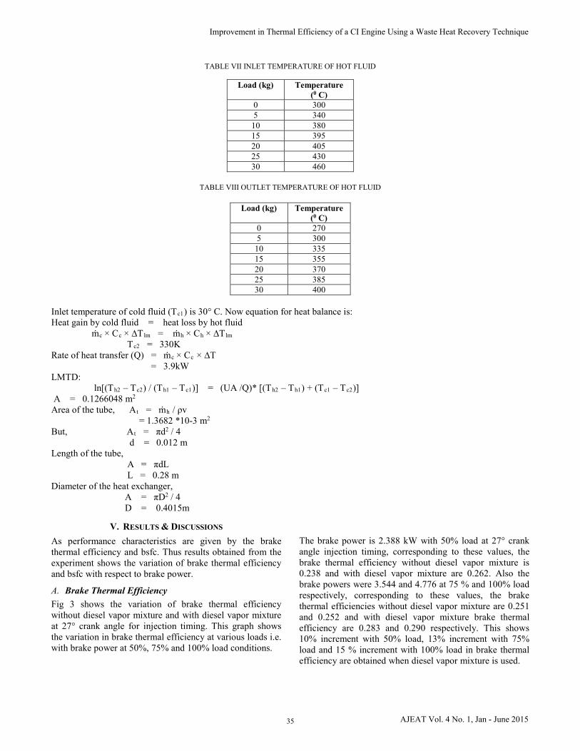
TABLE VII INLET TEMPERATURE OF HOT FLUID
Load (kg) Temperature (0 C)
0 300 5 340
10 380 15 395 20 405 25 430 30 460
TABLE VIII OUTLET TEMPERATURE OF HOT FLUID
Load (kg) Temperature (0 C)
0 270 5 300
10 335 15 355 20 370 25 385 30 400
Inlet temperature of cold fluid (Tc1) is 30° C. Now equation for heat balance is: Heat gain by cold fluid = heat loss by hot fluid
ṁc × Cc × ∆Tlm = ṁh × Ch × ∆Tlm Tc2 = 330K
Rate of heat transfer (Q) = ṁc × Cc × ∆T = 3.9kW
LMTD: ln[(Th2 – Tc2) / (Th1 – Tc1)] = (UA /Q)* [(Th2 – Th1) + (Tc1 – Tc2)]
A = 0.1266048 m2 Area of the tube, At = ṁh / ρv
= 1.3682 *10-3 m2 But, At = πd2 / 4
d = 0.012 m Length of the tube,
A = πdL L = 0.28 m
Diameter of the heat exchanger, A = πD2 / 4 D = 0.4015m
V. RESULTS & DISCUSSIONS
As performance characteristics are given by the brake thermal efficiency and bsfc. Thus results obtained from the experiment shows the variation of brake thermal efficiency and bsfc with respect to brake power.
A. Brake Thermal EfficiencyFig 3 shows the variation of brake thermal efficiency without diesel vapor mixture and with diesel vapor mixture at 27° crank angle for injection timing. This graph shows the variation in brake thermal efficiency at various loads i.e. with brake power at 50%, 75% and 100% load conditions.
The brake power is 2.388 kW with 50% load at 27° crank angle injection timing, corresponding to these values, the brake thermal efficiency without diesel vapor mixture is 0.238 and with diesel vapor mixture are 0.262. Also the brake powers were 3.544 and 4.776 at 75 % and 100% load respectively, corresponding to these values, the brake thermal efficiencies without diesel vapor mixture are 0.251 and 0.252 and with diesel vapor mixture brake thermal efficiency are 0.283 and 0.290 respectively. This shows 10% increment with 50% load, 13% increment with 75% load and 15 % increment with 100% load in brake thermal efficiency are obtained when diesel vapor mixture is used.
35
Improvement in Thermal Efficiency of a CI Engine Using a Waste Heat Recovery Technique
AJEAT Vol. 4 No. 1, Jan - June 2015
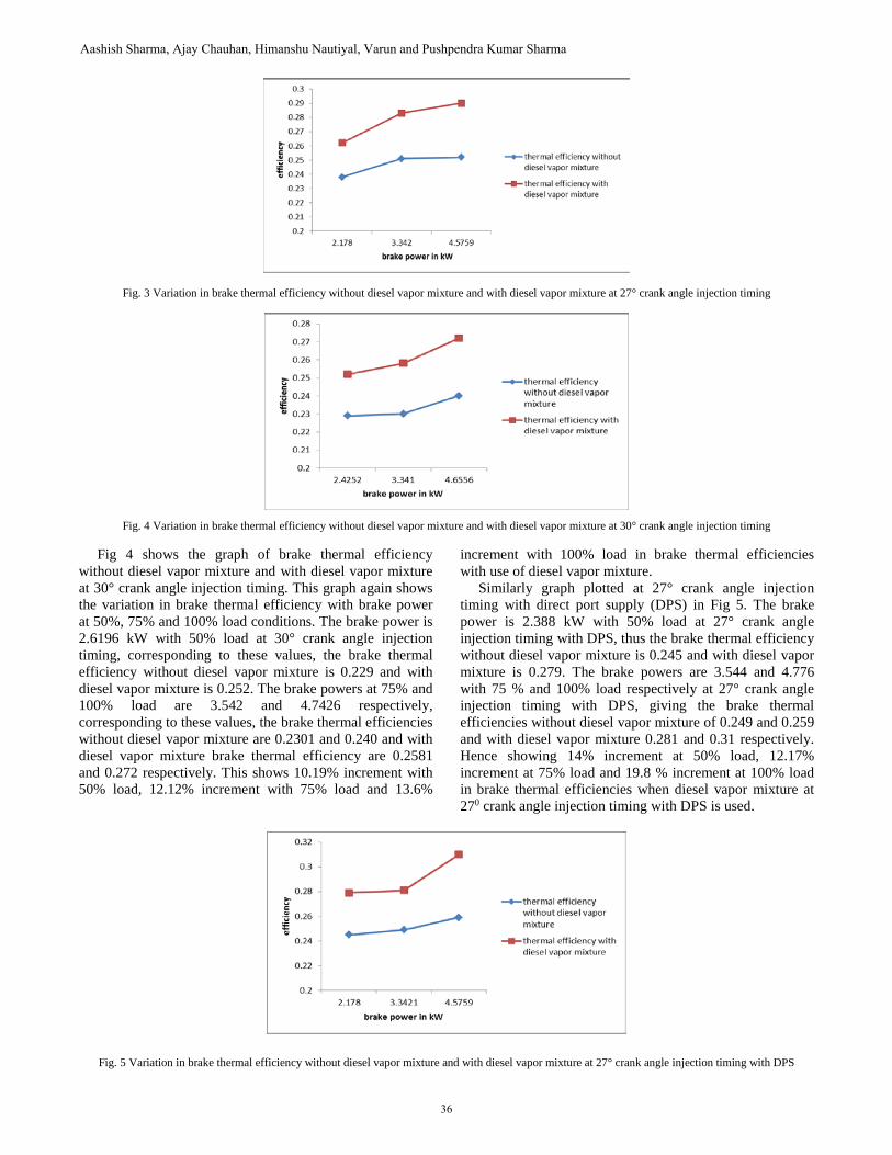
Fig. 3 Variation in brake thermal efficiency without diesel vapor mixture and with diesel vapor mixture at 27° crank angle injection timing
Fig. 4 Variation in brake thermal efficiency without diesel vapor mixture and with diesel vapor mixture at 30° crank angle injection timing
Fig 4 shows the graph of brake thermal efficiency without diesel vapor mixture and with diesel vapor mixture at 30° crank angle injection timing. This graph again shows the variation in brake thermal efficiency with brake power at 50%, 75% and 100% load conditions. The brake power is 2.6196 kW with 50% load at 30° crank angle injection timing, corresponding to these values, the brake thermal efficiency without diesel vapor mixture is 0.229 and with diesel vapor mixture is 0.252. The brake powers at 75% and 100% load are 3.542 and 4.7426 respectively, corresponding to these values, the brake thermal efficiencies without diesel vapor mixture are 0.2301 and 0.240 and with diesel vapor mixture brake thermal efficiency are 0.2581 and 0.272 respectively. This shows 10.19% increment with 50% load, 12.12% increment with 75% load and 13.6%
increment with 100% load in brake thermal efficiencies with use of diesel vapor mixture. Similarly graph plotted at 27° crank angle injection timing with direct port supply (DPS) in Fig 5. The brake power is 2.388 kW with 50% load at 27° crank angle injection timing with DPS, thus the brake thermal efficiency without diesel vapor mixture is 0.245 and with diesel vapor mixture is 0.279. The brake powers are 3.544 and 4.776 with 75 % and 100% load respectively at 27° crank angle injection timing with DPS, giving the brake thermal efficiencies without diesel vapor mixture of 0.249 and 0.259 and with diesel vapor mixture 0.281 and 0.31 respectively. Hence showing 14% increment at 50% load, 12.17% increment at 75% load and 19.8 % increment at 100% load in brake thermal efficiencies when diesel vapor mixture at 270 crank angle injection timing with DPS is used.
Fig. 5 Variation in brake thermal efficiency without diesel vapor mixture and with diesel vapor mixture at 27° crank angle injection timing with DPS
36
Aashish Sharma, Ajay Chauhan, Himanshu Nautiyal, Varun and Pushpendra Kumar Sharma
AJEAT Vol. 4 No. 1, Jan - June 2015
At 27° injection timing with DPS, the increment in brake thermal efficiency is more because of charge potential is better than to others. There is a fine mixing of charges inside the engine cylinder at this injection timing and reduce the delay period for combustion causes peak pressure increase and less fuel consumption achieved.
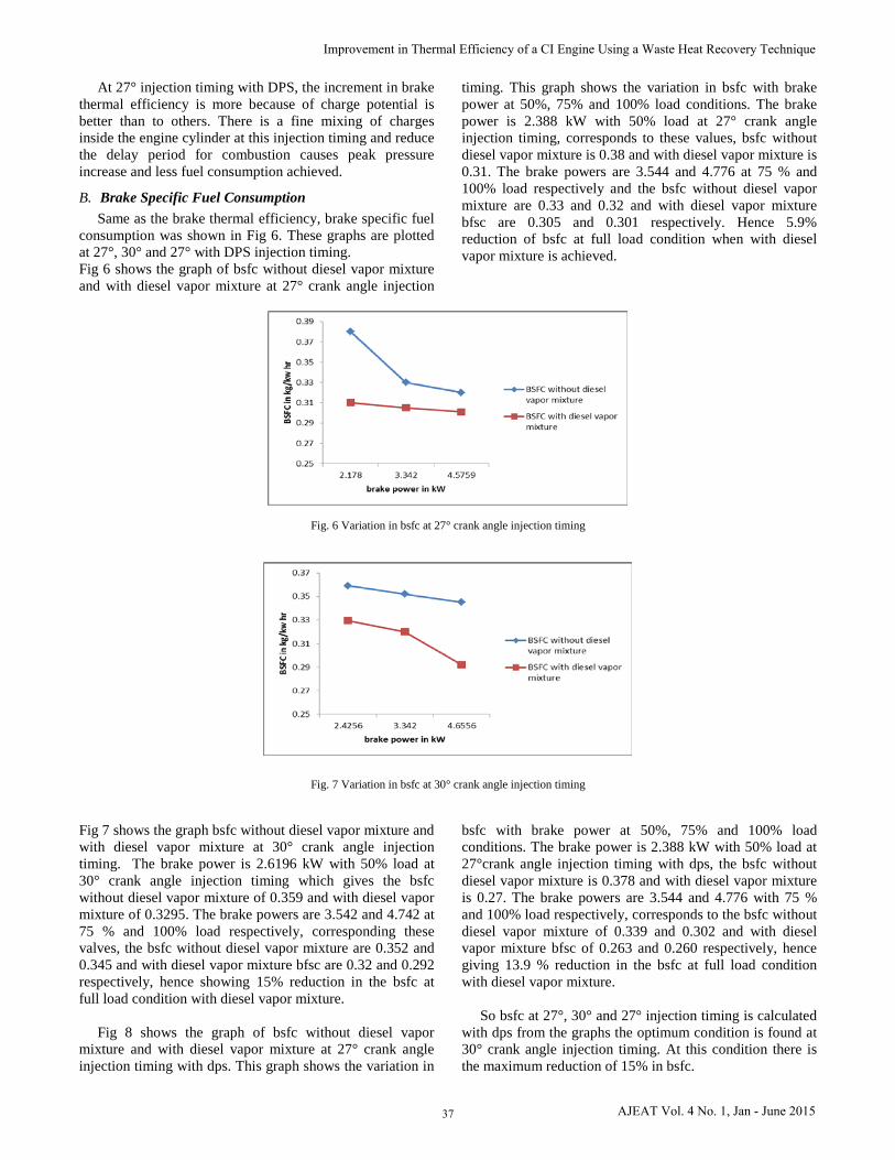
B. Brake Specific Fuel ConsumptionSame as the brake thermal efficiency, brake specific fuel
consumption was shown in Fig 6. These graphs are plotted at 27°, 30° and 27° with DPS injection timing. Fig 6 shows the graph of bsfc without diesel vapor mixture and with diesel vapor mixture at 27° crank angle injection
timing. This graph shows the variation in bsfc with brake power at 50%, 75% and 100% load conditions. The brake power is 2.388 kW with 50% load at 27° crank angle injection timing, corresponds to these values, bsfc without diesel vapor mixture is 0.38 and with diesel vapor mixture is 0.31. The brake powers are 3.544 and 4.776 at 75 % and 100% load respectively and the bsfc without diesel vapor mixture are 0.33 and 0.32 and with diesel vapor mixture bfsc are 0.305 and 0.301 respectively. Hence 5.9% reduction of bsfc at full load condition when with diesel vapor mixture is achieved.
Fig. 6 Variation in bsfc at 27° crank angle injection timing
Fig. 7 Variation in bsfc at 30° crank angle injection timing
Fig 7 shows the graph bsfc without diesel vapor mixture and with diesel vapor mixture at 30° crank angle injection timing. The brake power is 2.6196 kW with 50% load at 30° crank angle injection timing which gives the bsfc without diesel vapor mixture of 0.359 and with diesel vapor mixture of 0.3295. The brake powers are 3.542 and 4.742 at 75 % and 100% load respectively, corresponding these valves, the bsfc without diesel vapor mixture are 0.352 and 0.345 and with diesel vapor mixture bfsc are 0.32 and 0.292 respectively, hence showing 15% reduction in the bsfc at full load condition with diesel vapor mixture.
Fig 8 shows the graph of bsfc without diesel vapor mixture and with diesel vapor mixture at 27° crank angle injection timing with dps. This graph shows the variation in
bsfc with brake power at 50%, 75% and 100% load conditions. The brake power is 2.388 kW with 50% load at 27°crank angle injection timing with dps, the bsfc without diesel vapor mixture is 0.378 and with diesel vapor mixture is 0.27. The brake powers are 3.544 and 4.776 with 75 % and 100% load respectively, corresponds to the bsfc without diesel vapor mixture of 0.339 and 0.302 and with diesel vapor mixture bfsc of 0.263 and 0.260 respectively, hence giving 13.9 % reduction in the bsfc at full load condition with diesel vapor mixture.
So bsfc at 27°, 30° and 27° injection timing is calculated with dps from the graphs the optimum condition is found at 30° crank angle injection timing. At this condition there is the maximum reduction of 15% in bsfc.
37
Improvement in Thermal Efficiency of a CI Engine Using a Waste Heat Recovery Technique
AJEAT Vol. 4 No. 1, Jan - June 2015
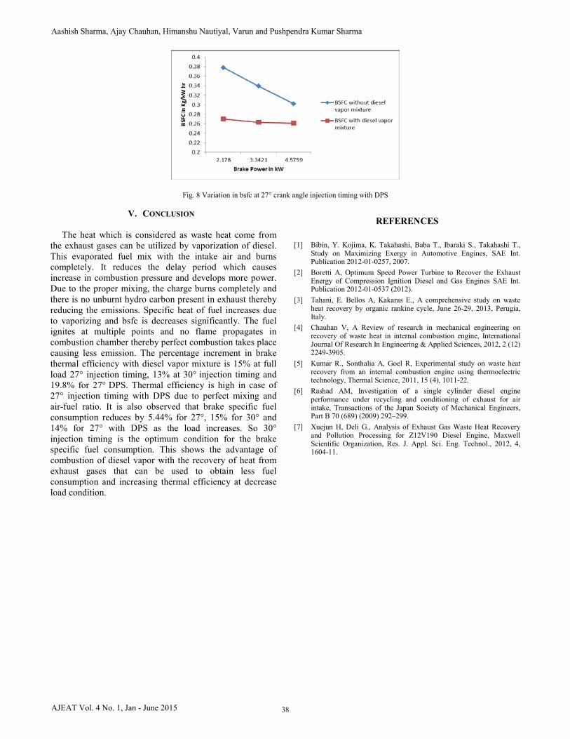
Fig. 8 Variation in bsfc at 27° crank angle injection timing with DPS
V. CONCLUSION
The heat which is considered as waste heat come from the exhaust gases can be utilized by vaporization of diesel. This evaporated fuel mix with the intake air and burns completely. It reduces the delay period which causes increase in combustion pressure and develops more power. Due to the proper mixing, the charge burns completely and there is no unburnt hydro carbon present in exhaust thereby reducing the emissions. Specific heat of fuel increases due to vaporizing and bsfc is decreases significantly. The fuel ignites at multiple points and no flame propagates in combustion chamber thereby perfect combustion takes place causing less emission. The percentage increment in brake thermal efficiency with diesel vapor mixture is 15% at full load 27° injection timing, 13% at 30° injection timing and 19.8% for 27° DPS. Thermal efficiency is high in case of 27° injection timing with DPS due to perfect mixing and air-fuel ratio. It is also observed that brake specific fuel consumption reduces by 5.44% for 27°, 15% for 30° and 14% for 27° with DPS as the load increases. So 30° injection timing is the optimum condition for the brake specific fuel consumption. This shows the advantage of combustion of diesel vapor with the recovery of heat from exhaust gases that can be used to obtain less fuel consumption and increasing thermal efficiency at decrease load condition.
REFERENCES
[1] Bibin, Y. Kojima, K. Takahashi, Baba T., Ibaraki S., Takahashi T.,Study on Maximizing Exergy in Automotive Engines, SAE Int.Publication 2012-01-0257, 2007.
[2] Boretti A, Optimum Speed Power Turbine to Recover the ExhaustEnergy of Compression Ignition Diesel and Gas Engines SAE Int.Publication 2012-01-0537 (2012).
[3] Tahani, E. Bellos A, Kakaras E., A comprehensive study on wasteheat recovery by organic rankine cycle, June 26-29, 2013, Perugia,Italy.
[4] Chauhan V, A Review of research in mechanical engineering onrecovery of waste heat in internal combustion engine, International Journal Of Research In Engineering & Applied Sciences, 2012, 2 (12) 2249-3905.
[5] Kumar R., Sonthalia A, Goel R, Experimental study on waste heatrecovery from an internal combustion engine using thermoelectrictechnology, Thermal Science, 2011, 15 (4), 1011-22.
[6] Rashad AM, Investigation of a single cylinder diesel engineperformance under recycling and conditioning of exhaust for airintake, Transactions of the Japan Society of Mechanical Engineers,Part B 70 (689) (2009) 292–299.
[7] Xuejun H, Deli G., Analysis of Exhaust Gas Waste Heat Recoveryand Pollution Processing for Z12V190 Diesel Engine, MaxwellScientific Organization, Res. J. Appl. Sci. Eng. Technol., 2012, 4,1604-11.
38
Aashish Sharma, Ajay Chauhan, Himanshu Nautiyal, Varun and Pushpendra Kumar Sharma
AJEAT Vol. 4 No. 1, Jan - June 2015