Embed Size (px)
Citation preview
Improvement of field of vision in dirty environments
- A case study on Volvo wheel loaders
Master thesis Advanced level, 30hp
Product- and Process development
Dennis Björnberg
Thesis nr:
Supervisor (VOLVO CE): Robert Sundkvist
Supervisor (Mälardalen University):Bengt Gustafsson
Examiner: Sten Grahn
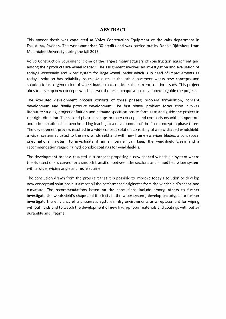
ABSTRACT
This master thesis was conducted at Volvo Construction Equipment at the cabs department in
Eskilstuna, Sweden. The work comprises 30 credits and was carried out by Dennis Björnberg from
Mälardalen University during the fall 2015.
Volvo Construction Equipment is one of the largest manufacturers of construction equipment and
among their products are wheel loaders. The assignment involves an investigation and evaluation of
today’s windshield and wiper system for large wheel loader which is in need of improvements as
today’s solution has reliability issues. As a result the cab department wants new concepts and
solution for next generation of wheel loader that considers the current solution issues. This project
aims to develop new concepts which answer the research questions developed to guide the project.
The executed development process consists of three phases; problem formulation, concept
development and finally product development. The first phase, problem formulation involves
literature studies, project definition and demand specifications to formulate and guide the project in
the right direction. The second phase develops primary concepts and comparisons with competitors
and other solutions in a benchmarking leading to a development of the final concept in phase three.
The development process resulted in a wide concept solution consisting of a new shaped windshield,
a wiper system adjusted to the new windshield and with new frameless wiper blades, a conceptual
pneumatic air system to investigate if an air barrier can keep the windshield clean and a
recommendation regarding hydrophobic coatings for windshield´s.
The development process resulted in a concept proposing a new shaped windshield system where
the side sections is curved for a smooth transition between the sections and a modified wiper system
with a wider wiping angle and more square
The conclusion drawn from the project it that it is possible to improve today’s solution to develop
new conceptual solutions but almost all the performance originates from the windshield´s shape and
curvature. The recommendations based on the conclusions include among others to further
investigate the windshield´s shape and it effects in the wiper system, develop prototypes to further
investigate the efficiency of a pneumatic system in dry environments as a replacement for wiping
without fluids and to watch the development of new hydrophobic materials and coatings with better
durability and lifetime.

ACKNOWLEDGMENTS
I would like to thank my company supervisor Robert Sundkvist (Manager Cab & Operators
Environment) for the opportunity to execute this interesting thesis work at Volvo CE during the
autumn 2015. I would also like to thank the entire cab department at Volvo CE in Eskilstuna for a
welcoming atmosphere, rewarding discussions and advices during the project.
I would like to give an especially large thanks to Nawrous Mahmoud (Lead Engineer WLO CAB) for all
the committed help, guidance and encouragement given during the project.
Finally I would like to thank my supervisor at Mälardalen University Bengt Gustafsson for guidance
and feedback during the project.
Thank you!
ACRONYMS & ABBREVIATIONS
CAD Computer aided design
MDH Mälardalen university
FMEA Failure Mode and Effect Analysis
FOPS Falling Object Protective Structure
GDP Global Development Process
PDM Product Data Management
ROPS Roll Over Protective Structure
R&D Research & Development
Volvo CE Volvo Construction Equipment
WLO Wheel loader
Content
1 Introduction ..................................................................................................................................... 1
1.1 VOLVO CE ................................................................................................................................ 1
1.2 Project background ................................................................................................................. 1
1.3 Problem formulation ............................................................................................................... 1
1.4 Project Aim .............................................................................................................................. 1
1.5 Research questions.................................................................................................................. 2
1.6 Delimitations ........................................................................................................................... 2
1.7 Project directives ..................................................................................................................... 2
2 Research methodology .................................................................................................................... 3
2.1 Product development process ................................................................................................ 3
2.2 Data collecting method ........................................................................................................... 4
2.3 Tools ........................................................................................................................................ 5
2.4 Product development methods and tools .............................................................................. 6
3 Theoretical framework .................................................................................................................... 9
3.1 Volvo CE´s Wheel loader ......................................................................................................... 9
3.2 Overview of windshield´s and wiper systems ....................................................................... 10
3.3 Windshield systems without wipers ..................................................................................... 13
3.4 Regulations and standards .................................................................................................... 15
4 Empiric study ................................................................................................................................. 17
4.1 Phase one - Problem definition ............................................................................................. 17
4.2 Phase two – Concept generation .......................................................................................... 21
4.3 Phase three – Concept development .................................................................................... 33
5 Results ........................................................................................................................................... 39
5.1 Final concept ......................................................................................................................... 39
5.2 Subsystems ............................................................................................................................ 40
5.3 Prototype testing’s ................................................................................................................ 41
6 Analysis .......................................................................................................................................... 43
6.1 Answers to the research questions ....................................................................................... 43
6.2 Evaluation of demand specification ...................................................................................... 44
7 Conclusions and recommendations .............................................................................................. 46
7.1 Conclusions ............................................................................................................................ 46
7.2 Recommendations................................................................................................................. 47
8 Bibliography ................................................................................................................................... 49
9 Appendixes .................................................................................................................................... 52
Figures
Figure 1 – The product development process (Ulrich & Eppinger, 2008) ............................................... 3
Figure 2 - The Global Development Process (Volvo CE, 2007) ................................................................ 4
Figure 3 – Adapted product development process ................................................................................. 4
Figure 4 - Wheel loader L180 (Internal document) ................................................................................. 9
Figure 5 - Overview of wiper systems ................................................................................................... 11
Figure 6 - Sweep patterns ..................................................................................................................... 11
Figure 7 - Depression angle (Waken, 2015) .......................................................................................... 12
Figure 8 - Wiper area quality (internal document) ............................................................................... 12
Figure 9 - Comparison between a smooth surface and the surface of a lotus leaf (Barthlott &
Neinhuis, 1997, p. 6).............................................................................................................................. 13
Figure 10 - Contact angle (Griggs, 2012) ............................................................................................... 13
Figure 11 - ISO 5006 test circle (The International Organization for Standardization, 2006) ............... 16
Figure 12 - CAD-model with illustrated wiper area ............................................................................... 17
Figure 13 - Important visual parts (internal document) ........................................................................ 18
Figure 14 - Mapping of important parts visible throught the front windshield .................................... 18
Figure 15 - View in dirty environment (internal document) ................................................................. 20
Figure 16 - Wiper blade moving outside of windscreen (internal document) ...................................... 20
Figure 17 - Concept 1 ............................................................................................................................ 28
Figure 18 – Concept 2 ............................................................................................................................ 29
Figure 19 - Concept 3 ............................................................................................................................ 29
Figure 20 - Concept 4 ............................................................................................................................ 30
Figure 21 - Concept 5 ............................................................................................................................ 30
Figure 22 - Concept 6 ............................................................................................................................ 31
Figure 23 - Concept 7 ............................................................................................................................ 31
Figure 24 - Todays windshield´s curvature ............................................................................................ 33
Figure 25- Detail development, windshield .......................................................................................... 34
Figure 26 - Conceptual sweep area ....................................................................................................... 34
Figure 27 – Prototype rig ....................................................................................................................... 36
Figure 28 - Final concept, windshield and wiper system ...................................................................... 39
Figure 29 - Proposed windshield shape ................................................................................................ 40
Figure 30 - Proposed sweep pattern ..................................................................................................... 40
Figure 31 - Nozzles from lechler ............................................................................................................ 41
Figure 32 - Air knife ............................................................................................................................... 42

Figures
Table 1 - Demand specification ............................................................................................................. 20
Table 2 - Function analysis .................................................................................................................... 21
Table 3 - Benchmarking ......................................................................................................................... 22
Table 4 – Summary of benchmarking .................................................................................................... 23
Table 5- Pugh’s matrix, evaluation of windshield´s solutions ............................................................... 27
Table 6 - Pugh´s matrix, evaluation of cleaning system solutions ........................................................ 28
Table 7 - Pugh´s matrix, evaluation of final concepts ........................................................................... 32
1
1 Introduction
This report covers a thesis work on advanced level commissioned by the cab division at Volvo
Construction Equipment (Volvo CE) located in Eskilstuna.
1.1 VOLVO CE In 1832 Johan Theofron Munktell founded what would become Volvo CE in Eskilstuna which is one of
the oldest companies still active in producing and developing construction equipment. The company
was a repair shop until 1906 when they started manufacturing their first vehicle and 1932 Munktell
merged with a company funded by the two Bolinder brothers and AB Bolinder-Munktell were
founded. During the following years the company gained a good reputation for their high quality.
During 1950 AB Bolinder-Munktell were bought by Volvo group and today the Volvo group is one of
the leading companies in manufacturing of trucks, buses, construction equipment and drive systems
for marine and industrial applications.
1.2 Project background The windshield solution and primary the wiper systems on today’s wheel loaders made by Volvo CE
are in need for improvements as the system lacks in wiper quality of the sweep areas and reliability.
There has been some investigation and development over the last machine generations as projects
involving choices of wiper blades, motors and mechanical linkage has been carried out. The
manufacturing processes for the mechanical linkage have also been evaluated and improved but the
reliability issues still exist in today’s wiper system.
As a result the cab department at Volvo CE wants new concepts and solutions for the next generation
of wheel loaders that takes todays issues into consideration. The concepts also have the liberty to
change the windshields shape and implement new methods and techniques for cleaning the
windshield.
1.3 Problem formulation The given problem was to analyze the current design and specify the needed sweep area for
windscreen wipers for wheel loaders. From this analysis a new design for the wiping area should be
recommended that minimize dirt spray and maximize sweep area and the primary field of vision. A
design for new mechanics to achieve the recommended sweep area for the wipers should be
constructed and presented together with new solutions.
1.4 Project Aim The aim of this project is through analyze of today’s solution, competitors and research of windshield
and cleaning systems investigate whether it is possible to improve the cleaning solution for drivers of
Volvo wheel loaders. The project also aims to investigate if it is possible to increase and improve the
primary field of vision together with improving the quality of the secondary field of vision for the
operator.
Is it possible to improve today’s solutions and produce one or more concepts that can be
implemented in the development of the next generation of Volvo CE wheel loaders?
2
1.5 Research questions Three research questions were formulated to help guide the project without restricting or specifying
it. The conclusion of this report should have answered the following research questions at the end of
the project:
RQ1: How can the operator get an as “unlimited” view through the front windshield as possible?
RQ2: How can the primary field of vision be increased?
RQ3: How can the secondary field of vision get an improved visibility?
1.6 Delimitations In accordance with Volvo CE and Mälardalen University (MDH) delimitations have been determined.
The thesis work consists of 30 credits which translate to 20 weeks with 40 hours of worktime. The
time for the project is limited from 31 August 2015 to 15 January 2016 and is primary located at
Volvo CE in Eskilstuna.
The project compromises of product development, construction, and 3D-modelling of the
windshield, wiper system and new conceptual solutions.
Product development:
- The project consists of an identified problem from Volvo CE and takes no consideration of
customer’s needs. The demands are the ones the client have determined and identified.
Construction:
- The construction work refers to Volvo CE large wheel loaders in the range from L60 to L350
which shares the same cab.
- No work regarding programing and regulation of the system will be taken
- The definition of the eye point position are the median value defined by Volvo CE
- The windshield´s interface against the A-pillars, roof beams should not be changed
3D-model:
- The product will primary be constructed and presented in CATIA V5
1.7 Project directives The product development process shall take The Global Development Process (GDP) into account as
a requirement from Volvo CE. Volvo CE main 3D development tool is CATIA V5 and the made
concepts and result shall primary be constructed and presented in CATIA V5.
3
2 Research methodology
This project in form of a case study has been initiated on behalf of Volvo CE cab department. The
project contains a broad study with qualitative primary and quantitative secondary data have been
used to answer the research questions. The qualitative primary data collection has been done
through field studies at Volvo CE in Eskilstuna and interviews. The quantitative secondary data have
been acquired from printed sources and searches in web based databases as google scholar and SAE
International.
The methodology in this project initiates with a broad information gathering to acquire knowledge in
the problem area and what the latest science says in fields useful for the study. The information is
utilized to determine the delimitations and goals which later will determine the demand
specification. From the demand specification and the gathered knowledge, concepts are developed
with support from product development tools and methods. The concepts are then developed and
evaluated which leads to one final concept for further development. To assure the quality of the
result the product development utilizes proven methodologies and tools. The following chapter
describes the used methodology, development process and tools utilized to support and assure
quality the project.
2.1 Product development process There are many different ways of handling product development. In most cases there is useful to use
a proven effective product development process to successfully execute the project. The product
development process in this project is a adapted version of Ulrich and Eppingers development
process from the book Product Design and Development (Ulrich & Eppinger, 2008) and Volvo CEs
own development process, the GDP (Volvo CE, 2007).
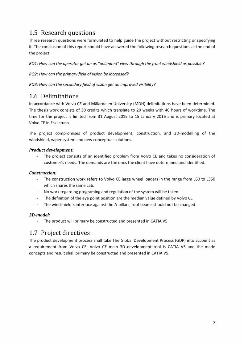
2.1.1 Ulrich and Eppinger´s development process The process builds around six steps as shown in Figure 1 proposed by Ulrich and Eppinger (2008). The
process describes a methodology starting with planning and ending with production start and
product launch.
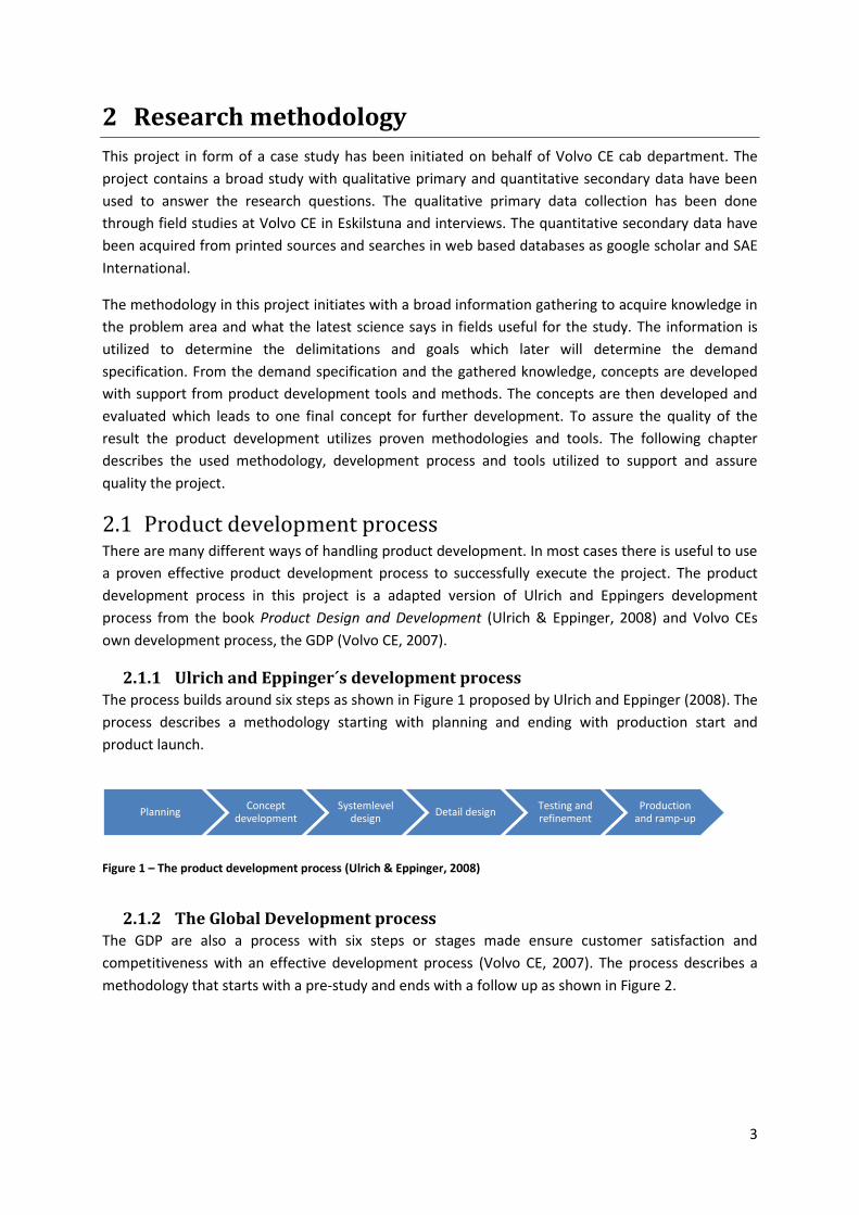
2.1.2 The Global Development process The GDP are also a process with six steps or stages made ensure customer satisfaction and
competitiveness with an effective development process (Volvo CE, 2007). The process describes a
methodology that starts with a pre-study and ends with a follow up as shown in Figure 2.
Planning Concept
development Systemlevel
design Detail design
Testing and refinement
Production and ramp-up
Figure 1 – The product development process (Ulrich & Eppinger, 2008)
4
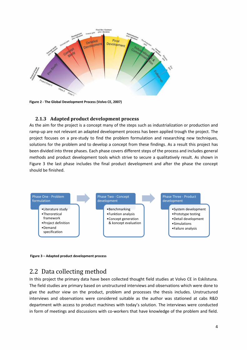
2.1.3 Adapted product development process As the aim for the project is a concept many of the steps such as industrialization or production and
ramp-up are not relevant an adapted development process has been applied trough the project. The
project focuses on a pre-study to find the problem formulation and researching new techniques,
solutions for the problem and to develop a concept from these findings. As a result this project has
been divided into three phases. Each phase covers different steps of the process and includes general
methods and product development tools which strive to secure a qualitatively result. As shown in
Figure 3 the last phase includes the final product development and after the phase the concept
should be finished.
2.2 Data collecting method In this project the primary data have been collected thought field studies at Volvo CE in Eskilstuna.
The field studies are primary based on unstructured interviews and observations which were done to
give the author view on the product, problem and processes the thesis includes. Unstructured
interviews and observations were considered suitable as the author was stationed at cabs R&D
department with access to product machines with today’s solution. The interviews were conducted
in form of meetings and discussions with co-workers that have knowledge of the problem and field.
Figure 2 - The Global Development Process (Volvo CE, 2007)
Phase One - Problem formulation
•Literature study
•Theroretical framework
•Project definition
•Demand specification
Phase Two - Concept development
•Benchmarking
•Funktion analysis
•Concept generation & koncept evaluation
Phase Three - Product development
•System development
•Prototype testing
•Detail development
•Simulations
•Failure analysis
Figure 3 – Adapted product development process
5
The following people have been interviewed; company supervisor and lead engineer WLO CAB (Cab
& operators environment), Lead engineer ART CAB (Cab & operators environment) Engineer involved
in development of wiper and windshield for small wheel loaders (common solutions), Engineer
involved in project aimed to improve todays wiper system (Cab & operators environment), Engineer
specialized on visibility and regulations (common solutions).
The secondary data was found from different internet based sources and were the information used
in the literature review. This was considered to be suitable as the latest research and knowledge are
easiest to find online in research and technical papers. Used databases and search words is further
described in 2.3.1 Databases.
2.3 Tools A number of tools and methods were used in the project to support and secure a scientific
methodology. The used tools and its application are described below.
2.3.1 Databases As a first step in the gathering of knowledge searches in databases have been done. The databases
SAE International, InterRegs and Scopus have been used for research of relevant information for the
project. SAE International contains a large amount of technical reports in full text format and stating
itself as the ultimate knowledge source for mobility engineering (SAE International, 2015). InterRegs
is an online library for vehicle regulations covering global vehicle safety and emission regulations
(InterRegs, 2015).
The search word used in this thesis are, “Wiperless windshield”, “self-cleaning materials”, “lotus
effect”, “Hydrophobic coating”, “Windshield wiper”, “Wiper systems”, “pneumatic rain removal
system”.
2.3.2 Product development software In the projects Computer Aided Design (CAD) software and Product Data Management (PDM)
software were used to support the product development. The used software’s and their applications
are presented below.
CATIA V5
CATIA V5 is a CAD software developed by Dassault Systems and is used to construct and assemble
the product in a virtual environment. The software is also developed to produce drawings for
manufacturing (Dassault Systems, 2015). CATIA V5 is the CAD software used at Volvo CE and was
therefore deemed suitable to use in the development process.
SmarTeam
PDM software´s is used to handle large amounts of data and information and SmarTeam is the used
PDM software at Volvo CE. PDM systems are used to integrate information from CAD models and
assemblies together with drawings, technical requirements and other information regarding the
products. As a large amount of information is needed to be investigated and processed, the use of
SmarTeam were deemed relevant to use.
6
2.4 Product development methods and tools The used adapted product development process methodology in this project as shown in Figure 3 is
presented below.
2.4.1 Phase one The first phase, problem formulation aims to retrieve as much relevant information from primary and
secondary sources as possible to achieve a broad base of knowledge to apply in the project. The
phase also includes measures to limit and define the project width.
Project planning – Gantt-schedule
The key to effectively execute a project is planning. As the limited recourse in this project is time a
Gantt-schedule was used to plan and distribute the given time between all the needed activities. The
Gantt-schedule can be seen in appendix 1.
Pre-study
An initial pre-study was deemed relevant for the project where the goal was to understand and
define the aim and delimitations of the project. The current solutions for the windshield and wiper
system were therefore studied both in parts and in action. The wheel loader and its components
could easily be studied in CAD-programs and drawings where they were studied to see the geometry,
shape and assembly.
Field study
To investigate how the operator is affected by the windshield´s shapes, wiped area and where
important visible parts are visible through the windshield a field study were deemed relevant. The
field study was conducted on Volvo CE workshop and Customer Center in Eskilstuna.
Literature review
A literature review needs to be performed to raise the understanding and to be acquaint with the
available knowledge in the field (Kumar, 2005). The review will also give a good foundation for the
project as it will help with approach and methods supported by previous writings. The preformed
work and arguments will therefore have support from previously proven knowledge (Bell, 2006).
2.4.2 Phase two The second phase concept development is aimed to use the information from the first phase in idea
and concept generation tools.
Benchmarking
The first step to a broad concept development phase according to Ulrich and Eppinger (2008)is to
understand competitive products. Benchmarking is therefore used to evaluate solutions and
functions in the same product segment as well as ideas and functions from other market segments.
Different solution was evaluated to find benefits and limitations to use in the concept development.
The evaluated solutions were identified through research in literature and internal discussions at
Volvo CE.
7
Demand specification
To specify the demands in a structured way a demand specification was produced. The demand
specification is the document specifying the demands and properties the product need to have in
order to meet the customer’s demands and is to be used as a guiding document through the product
development process.
In the final demand specification was used as an analysis tool in the end of the project to evaluate
the final products design. Many of the demands could not be defined or were too difficult to define
with a measurable value and their value were therefore given the value “Yes”.
Function analysis
To specify and investigate the actual functions of the product a function analysis was done. These
functions is the divided in three levels, the main function defining the products man function,
necessary functions that is needed to fulfil the main function and desirable functions which supports
the necessary functions (Österlin, 2010). The analysis will also support the coming concept analysis as
it defines what functions the product needs to contain.
Concept generating
The concept generating and concept evaluation were executed in two cycles. In the first cycle general
conceptual solutions were compiled and evaluated and combined to one final general solution. The
combined general solution was then developed further into several concepts.
The first concept generation work was based on compiled general conceptual solutions found in the
pre-study, review and benchmarking. The solutions were categorized into different general
solutions.
Brainstorming
One tool used to produce potential solutions or concepts are brainstorming. The tool can be used
both in group and by individuals and according to Ulrich & Eppinger (2008)four guidelines that are
useful for improving the search are:
1. Suspend judgment
2. Generate a lot of ideas
3. Welcome ideas that may seem infeasible
4. Use graphical and physical media
The brainstorming process is a central step in the product development process to generate new
concepts and ideas. In this project the brainstorming process did not take regard to the limitations
and delimitations for the product to broaden the possible solutions for the problem involving the
field of vision of how to keep the windshield clean.
8
Concept evaluation
The concept evaluations in the product development process are vital pars as the concepts are
evaluated against each other and the demands regarding the product. There are several different
methods and tools to evaluate and eliminate concept
Pugh’s matrix
Pugh’s matrix is a matrix used to evaluate different concepts against each other based on de
products demands. Every concept is evaluated against one reference concept. The concepts are
listed in a table and are evaluated in different evaluation criteria’s if they surpass (+), are equivalent
(0) or inferior (-) to the reference concept. The purpose with Pugh’s matrix is to fast get an evaluation
of which concepts are the best and worth to develop further (Ulrich & Eppinger, 2008). The results
from Pugh’s matrix together with discussions were the foundation of choosing the concept to be
developed further.
2.4.3 Phase three In the final phase that focuses on product development the final concept or concepts are chosen the
development process focus into system and detail development of the affected components. Below
the processes and methods used in phase three are presented.
System and detail development
The system development aims to define the major subsystems and interfaces and refine industrial
design for the product (Ulrich & Eppinger, 2008). Following the system development is detail design
and development that aims to define the components geometry, material and tolerances (Ulrich &
Eppinger, 2008; Volvo CE, 2007).
Failure analysis
The possible risks and failures that can occur for a product can be investigated with a Failure mode
and effects analysis (FMEA) to scientifically evaluate the product. The risk analysis tool evaluates
different possible failures that can occur for the product and the effects they bring which them. The
analysis results in recommended actions for all possible failures to minimize or eliminate the failures
(Ulrich & Eppinger, 2008). The tool is one of the most important tools at Volvo CE as it verifies the
quality, reliability and performance of the product (Johannesson, et al., 2013), it is deemed
appropriate to apply this tool in the development process to ensure the developments quality.
Prototype
A physical prototype allows testing and experimentation which gives the development a possibility to
a deeper learning and if the product works (Ulrich & Eppinger, 2008). To test the function and
effects of the proposed conceptual solution during different circumstances it were deemed suitable
to manufacture a functional prototype in this project.
9
3 Theoretical framework
To get an understanding of how wiper systems work and why windshield´s and wipers are shapes as
they are a theoretical framework are presented in the following chapter. The knowledge and
framework are based on secondary information from a number of books, projects and research
papers to investigate the “State-of-practice” and “State-of-art” in the projects field.
3.1 Volvo CE´s Wheel loader A wheel loader is a construction machine designed to move and load various materials and is
commonly used on construction sites, timber yards and general working operations that need
landscaping and material moving among others (Bengtsson, 1995). Volvo CE has a large range of
wheel loader and the wheel loaders investigated in the project are largest wheel loaders ranging
from L60 to L350. The operating weight for these machines is between 11 tons for the lightest L60
and up to 54 tons for the heaviest L350. There is typical divider in the large wheel loader range, L60
to L120 wheel loader are used in varying areas where almost all wheel loaders larger than L120 are
used in producing manufacturing where they move large amounts of material. Common for all these
loaders are that they are built with the same cab.
As the wheel loader has several different uses they have different attachments which is used for
different operations. The most common used attachments are a variety of different buckets, forklifts
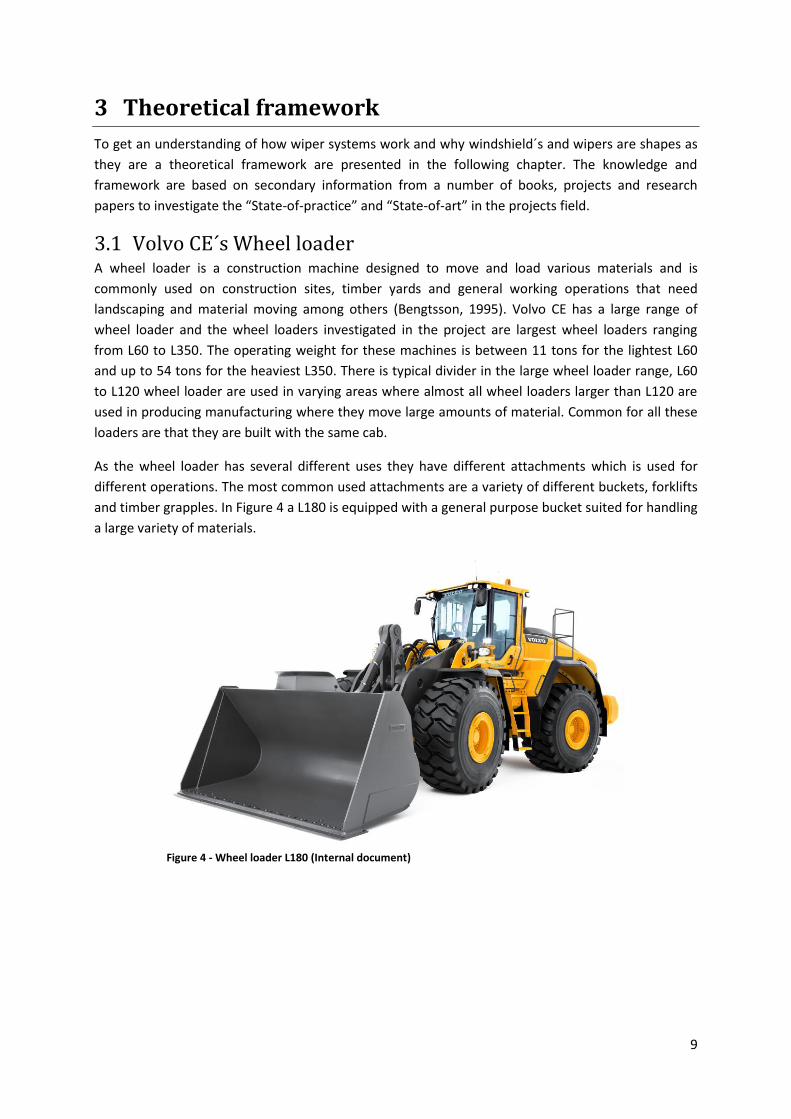
and timber grapples. In Figure 4 a L180 is equipped with a general purpose bucket suited for handling
a large variety of materials.
Figure 4 - Wheel loader L180 (Internal document)
10
3.1.1 Operating environment based on industry sector The wheel loader is used in a variety of environments and climates depending on the industry sector
and intended applications. Some of the sectors and intended applications with typical environment
and climate conditions are:
General construction – Executed under a wide variety of climates and temperatures. The
environment can vary from dry dust to mud or snow. Often multiple vehicles and people
moving in the same area.
Waste management – Most often done in a dry environment with much dust in the air.
Forestry - Executed under a wide variety of climates and temperatures. The environment can
vary from dry dust to mud or snow. Often many high lifts when loading and unloading timber
which requires a high and clean field of view.
Mining - Executed under a wide variety of climates and temperatures. The environment can
vary from dry dust to mud or snow. Often multiple vehicles and people moving in the same
area.
Agricultural - Executed under a wide variety of climates and temperatures. The environment
can vary from dry dust to mud or snow.
A general rule for different environments is that dry environments with dust in the air need a dry
cleaning system as wetting the windshield draws in more dust and creates mud on the windshield.
For wet environments mud often splashes up on the windshield and requires a large amount of
washer fluid for cleaning.
3.2 Overview of windshield´s and wiper systems When operating a machine the field of vision is important as the operator on vision to gather 90% of
the necessary information to maneuver the machine (Drury & Clement, 1978). As a result the quality
and cleanliness of the field of vision are important. The first affecting element to the field of vision is
the windshield.
3.2.1 Windshield´s The windshield or front window of a vehicle exists to protect the operator or passenger from flying
debris such as dirt (minerals, organic and biological), water, snow and ice. The windshield is
generally made of laminated safety glass which consists of two glass sheets with plastic layers
between (How Products Are Made, 2002; Pilkington, 2015a).
Initially the windshield´s shape was straight in one plane as it is easier to manufacture but in the
1950s the flat glass sheets where reheated and allowed to sag into curved molds. This technique was
used to get a curved shape and the same technique is still used today. For more complex shapes the
glass can be pressed between molds. The curved shape has benefits as it gives better aerodynamics
and can improve the field of vision (Pilkington, 2015b).
There are some limitations to the shaping as the curved windshield is shaped before they are
laminated together and need fine tolerances to fit together. There are also limitations to how far and
sharp the curvature can be as it is molded from a flat sheet. A good example is to try and shape a
piece of paper, the wrinkles that arises exist on the shaping of the windshield too (Eronen, 2011).
11
The shape on the windshield also affects the efficiency of the wiper system as the arm pressure and
the wiper blades pressure may vary with the curvature. The angle between the wiper blade and the
windshield is also affected by the windshield´s shape. Recommendation from suppliers and internal
discussions states that the curvature on the windshield should be even or similar at the top and
bottom for better quality of the wiper area and to lower wear on the wiper system.
3.2.2 Wiper systems The windshield wiper was invented about ten years after the first automobile were made and is
equipped on almost all motor vehicles today. The wiper system usually consists of wiper motors,
cranks, wiper arms and wiper blades. The wiper system most often includes a washing system
consisting of a pump, hoses, container for washer fluids and nozzles. Together these two systems
form a complete cleaning system that removes water, snow and dirt from the wiped area on the
windshield.
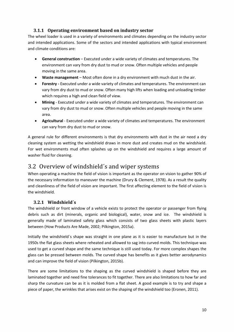
Wiper mechanics
There exist a large variety of wiper systems to keep the
windshield clean. Some of the more common solutions are
the five types of radial wiper systems are shown in Figure 5.
These systems are commonly mounted on vehicles with a
broad windshield and the most common is the tandem
system which is controlled by a four link mechanism
controlling the wiped area. In utility vehicle segment the
opposed system is becoming more common but have a non-
wiped area in the upper middle section of the windshield.
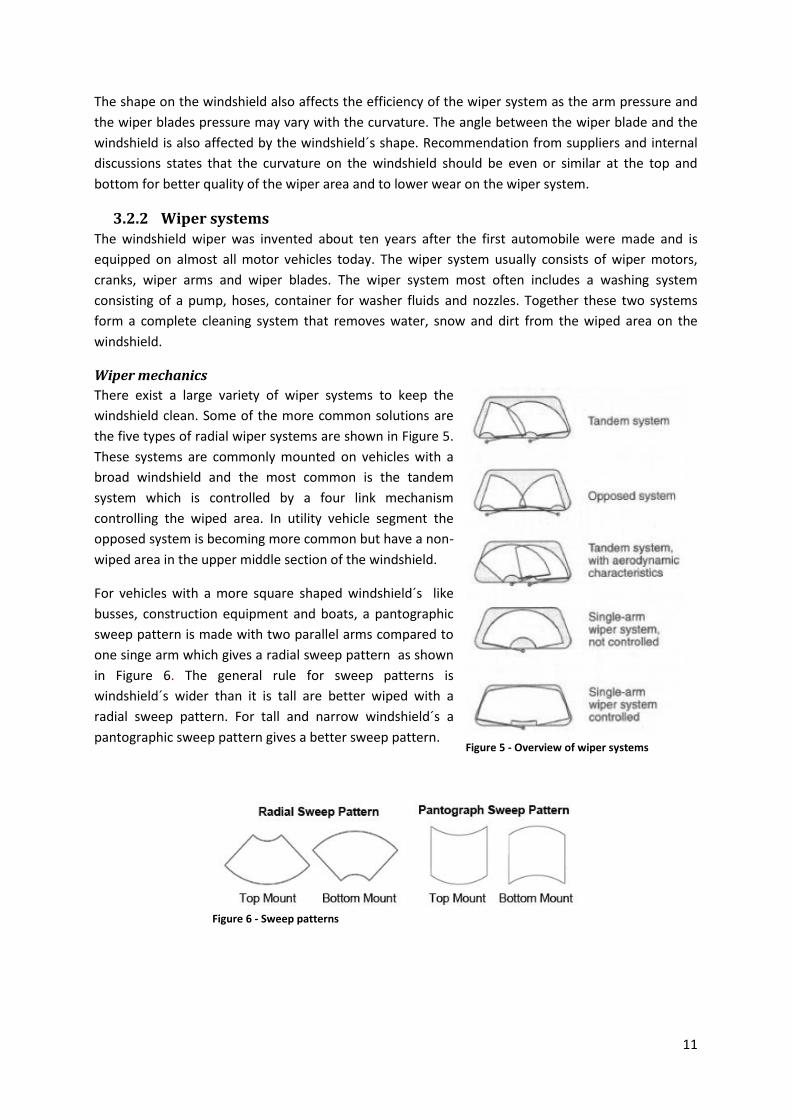
For vehicles with a more square shaped windshield´s like
busses, construction equipment and boats, a pantographic
sweep pattern is made with two parallel arms compared to
one singe arm which gives a radial sweep pattern as shown
in Figure 6. The general rule for sweep patterns is
windshield´s wider than it is tall are better wiped with a
radial sweep pattern. For tall and narrow windshield´s a
pantographic sweep pattern gives a better sweep pattern.
Figure 6 - Sweep patterns
Figure 5 - Overview of wiper systems
12
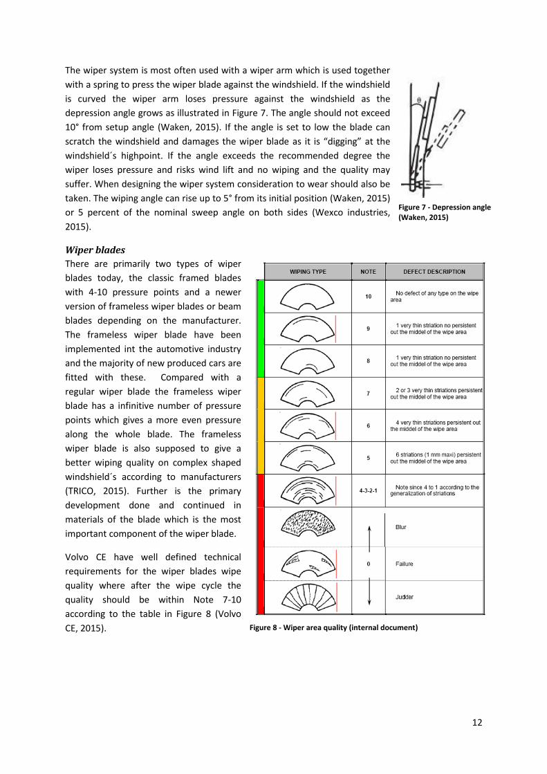
The wiper system is most often used with a wiper arm which is used together
with a spring to press the wiper blade against the windshield. If the windshield
is curved the wiper arm loses pressure against the windshield as the
depression angle grows as illustrated in Figure 7. The angle should not exceed
10° from setup angle (Waken, 2015). If the angle is set to low the blade can
scratch the windshield and damages the wiper blade as it is “digging” at the
windshield´s highpoint. If the angle exceeds the recommended degree the
wiper loses pressure and risks wind lift and no wiping and the quality may
suffer. When designing the wiper system consideration to wear should also be
taken. The wiping angle can rise up to 5° from its initial position (Waken, 2015)
or 5 percent of the nominal sweep angle on both sides (Wexco industries,
2015).
Wiper blades
There are primarily two types of wiper
blades today, the classic framed blades
with 4-10 pressure points and a newer
version of frameless wiper blades or beam
blades depending on the manufacturer.
The frameless wiper blade have been
implemented int the automotive industry
and the majority of new produced cars are
fitted with these. Compared with a
regular wiper blade the frameless wiper
blade has a infinitive number of pressure
points which gives a more even pressure
along the whole blade. The frameless
wiper blade is also supposed to give a
better wiping quality on complex shaped
windshield´s according to manufacturers
(TRICO, 2015). Further is the primary
development done and continued in
materials of the blade which is the most
important component of the wiper blade.
Volvo CE have well defined technical
requirements for the wiper blades wipe
quality where after the wipe cycle the
quality should be within Note 7-10
according to the table in Figure 8 (Volvo
CE, 2015).
Figure 7 - Depression angle (Waken, 2015)
Figure 8 - Wiper area quality (internal document)
13
The angle of attack or the contact angle between the wiper blade and windshield greatly affect the
performance and quality of the swiped area. Optimally the wiper blades angle should always have a
90° angle against the windshield´s surface so the wiper blade has the optimal angle of attack in both
directions.
3.3 Windshield systems without wipers There are large benefits if a technique can eliminates the wiper system function as no wiper arms
and wiper blades would obstruct the field of vision. No limitations made by the wiper arms reach
make it possible for larger clean areas. In this chapter three possible techniques or concepts are
described that have been evaluated through the project.
3.3.1 Self-cleaning materials When speaking of self-cleaning materials it often means a hydrophobic or super hydrophobic
surface. The artificial made hydrophobic surfaces usually is trying to mimic the surface structures of
self-cleaning organics and most often the surface structure on lotus leaves.
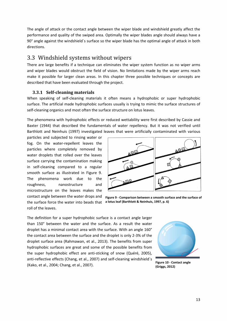
The phenomena with hydrophobic effects or reduced wettability were first described by Cassie and
Baxter (1944) that described the fundamentals of water repellency. But it was not verified until
Barthlott and Neinhuis (1997) investigated leaves that were artificially contaminated with various
particles and subjected to rinsing water or
fog. On the water-repellent leaves the
particles where completely removed by
water droplets that rolled over the leaves
surface carrying the contamination making
in self-cleaning compared to a regular
smooth surface as illustrated in Figure 9.
The phenomena work due to the
roughness, nanostructure and
microstructure on the leaves makes the
contact angle between the water drops and
the surface force the water into beads that
roll of the leaves.
The definition for a super hydrophobic surface is a contact angle larger
than 150° between the water and the surface. As a result the water
droplet has a minimal contact area with the surface. With an angle 160°
the contact area between the surface and the droplet is only 2-3% of the
droplet surface area (Rahmawan, et al., 2013). The benefits from super
hydrophobic surfaces are great and some of the possible benefits from
the super hydrophobic effect are anti-sticking of snow (Quéré, 2005),
anti-reflective effects (Chang, et al., 2007) and self-cleaning windshield´s
(Kako, et al., 2004; Chang, et al., 2007).
Figure 9 - Comparison between a smooth surface and the surface of a lotus leaf (Barthlott & Neinhuis, 1997, p. 6)
Figure 10 - Contact angle (Griggs, 2012)
14
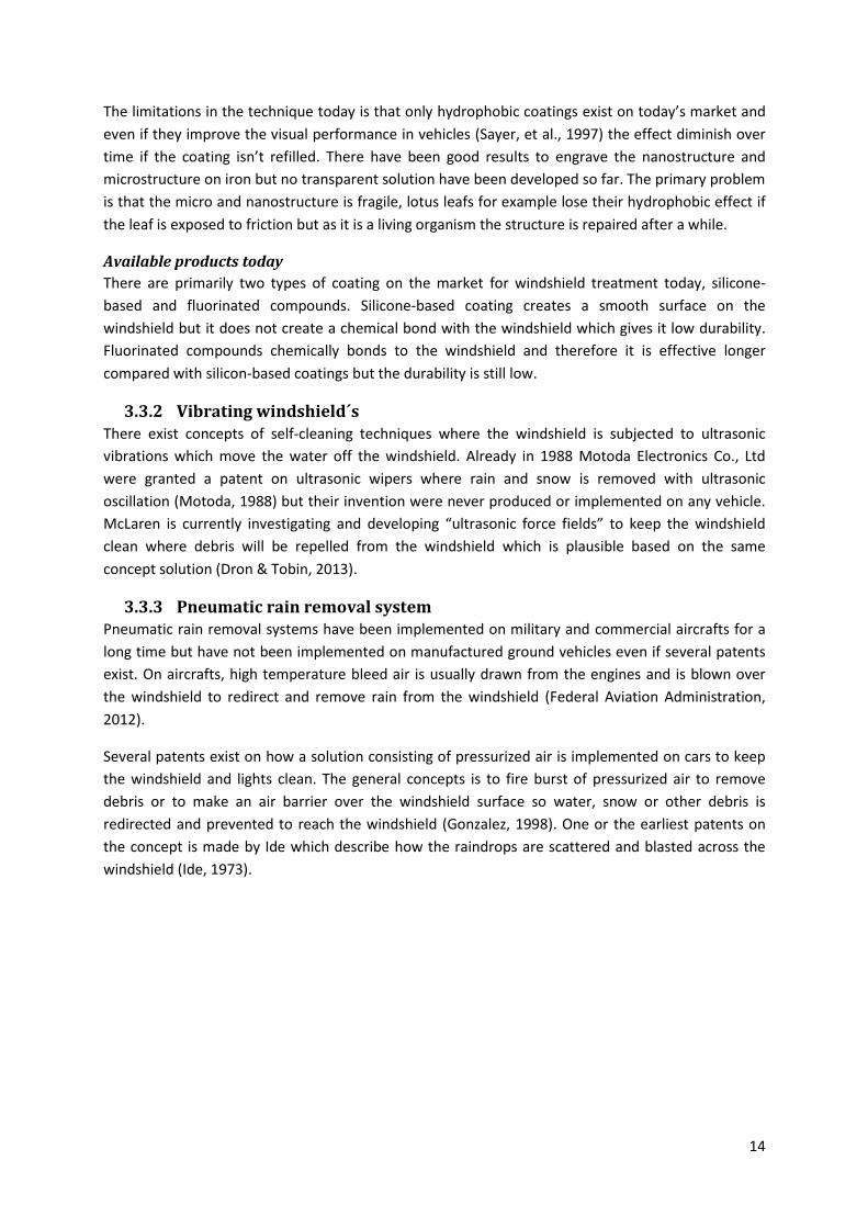
The limitations in the technique today is that only hydrophobic coatings exist on today’s market and
even if they improve the visual performance in vehicles (Sayer, et al., 1997) the effect diminish over
time if the coating isn’t refilled. There have been good results to engrave the nanostructure and
microstructure on iron but no transparent solution have been developed so far. The primary problem
is that the micro and nanostructure is fragile, lotus leafs for example lose their hydrophobic effect if
the leaf is exposed to friction but as it is a living organism the structure is repaired after a while.
Available products today
There are primarily two types of coating on the market for windshield treatment today, silicone-
based and fluorinated compounds. Silicone-based coating creates a smooth surface on the
windshield but it does not create a chemical bond with the windshield which gives it low durability.
Fluorinated compounds chemically bonds to the windshield and therefore it is effective longer
compared with silicon-based coatings but the durability is still low.
3.3.2 Vibrating windshield´s There exist concepts of self-cleaning techniques where the windshield is subjected to ultrasonic
vibrations which move the water off the windshield. Already in 1988 Motoda Electronics Co., Ltd
were granted a patent on ultrasonic wipers where rain and snow is removed with ultrasonic
oscillation (Motoda, 1988) but their invention were never produced or implemented on any vehicle.
McLaren is currently investigating and developing “ultrasonic force fields” to keep the windshield
clean where debris will be repelled from the windshield which is plausible based on the same
concept solution (Dron & Tobin, 2013).
3.3.3 Pneumatic rain removal system Pneumatic rain removal systems have been implemented on military and commercial aircrafts for a
long time but have not been implemented on manufactured ground vehicles even if several patents
exist. On aircrafts, high temperature bleed air is usually drawn from the engines and is blown over
the windshield to redirect and remove rain from the windshield (Federal Aviation Administration,
2012).
Several patents exist on how a solution consisting of pressurized air is implemented on cars to keep
the windshield and lights clean. The general concepts is to fire burst of pressurized air to remove
debris or to make an air barrier over the windshield surface so water, snow or other debris is
redirected and prevented to reach the windshield (Gonzalez, 1998). One or the earliest patents on
the concept is made by Ide which describe how the raindrops are scattered and blasted across the
windshield (Ide, 1973).
15
3.4 Regulations and standards In the following chapter the standards and regulations that have been used and taken into account in
this project are described. In the project European standards have been used as they have the
highest demands and regulations.
3.4.1 EN 474-1:2006+A4:2013 The standard EN 474-1:2006+A4:2013 are a safety standard that specifies the general safety
requirements for earth-moving machinery. The standard is applied to reduce risks and hazardous
situations during commissioning, operation and maintenance.
Regarding visibility and the operators field of view the standard states; “Earth-moving machines shall
be designed in accordance with ISO 5006:2006 so that the operator has sufficient visibility from the
operator's station in relation to the travel and work areas of the machine that are necessary for the
intended use of the machine. The travel mode as specified in ISO 5006:2006 is considered to be
representative for testing visibility in both travel and operating modes.” (European Committee for
Standardization, 2013, p. 21)
3.4.2 EN 15573:2008 The European standard EN 15573:2008 specifies the appropriate technical measurements to reduce
risks for road traveling earth-moving machines. The standard EN 15573 states the same as the
standard EN 474 and referees to the standard ISO 5006 to ensure visibility necessary for travel on
roads.
The standard also states that the front windshield must be fitted with a wiper system as it states;
“The front window shall be fitted with motorised windscreen wiper(s) and washer(s). The area swept
by the wiper(s) must ensure an unobstructed forward view corresponding to a chord of the semi-circle
of vision at least 8 m long within the sector of vision as described in ISO 5006. The wiper(s) shall have
a frequency of ≥ 20 cycles/min” (European Committee for Standardization, 2008, pp. 15-16). The
standard also states that the system shall function between -18°C and +65°C. For machines where
the maximum speed exceeds 30km/h only laminated windshield´s are permitted.
16
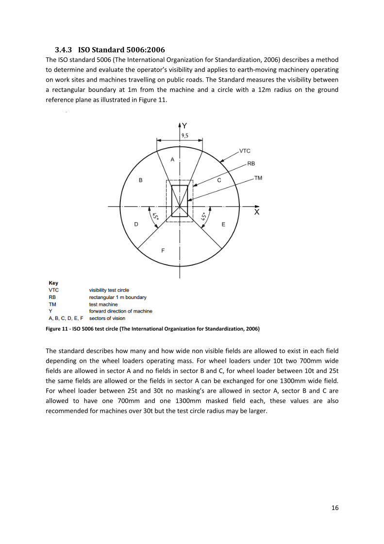
3.4.3 ISO Standard 5006:2006 The ISO standard 5006 (The International Organization for Standardization, 2006) describes a method
to determine and evaluate the operator’s visibility and applies to earth-moving machinery operating
on work sites and machines travelling on public roads. The Standard measures the visibility between
a rectangular boundary at 1m from the machine and a circle with a 12m radius on the ground
reference plane as illustrated in Figure 11.
The standard describes how many and how wide non visible fields are allowed to exist in each field
depending on the wheel loaders operating mass. For wheel loaders under 10t two 700mm wide
fields are allowed in sector A and no fields in sector B and C, for wheel loader between 10t and 25t
the same fields are allowed or the fields in sector A can be exchanged for one 1300mm wide field.
For wheel loader between 25t and 30t no masking’s are allowed in sector A, sector B and C are
allowed to have one 700mm and one 1300mm masked field each, these values are also
recommended for machines over 30t but the test circle radius may be larger.
Figure 11 - ISO 5006 test circle (The International Organization for Standardization, 2006)
17
4 Empiric study
In this chapter the execution of the GDP-process is described. The process follows the described
process in chapter 3.1 and covers all three phases of this project.
4.1 Phase one - Problem definition In this chapter the result from the pre-study that were conducted during the problem definition
phase which includes an analysis of Volvo CE current solution and a demand specification are
described.
4.1.1 Volvo CE current product In the analysis of the current solution two categories were investigated, “general solution” and “field
of vision and important visible parts”. The general solution investigates the shape and construction
used today and what the problems and disadvantages with it are. Field of vision and important visible
parts investigates the primary and secondary field of vision for the operator and what the necessary
field of vision are operate the machine.
General solution
The current solutions consist of a tree part windshield joined with a black adhesive. The two side
parts are flat laminated windshield´s that are connected to the A-pillars in the cabs framework. The
middle section is the only wiped section, the section has a complex form and is double curved with a
varying radius for the curves. The radius in the windshield´s top are larger compared to the bottom.
The wiping system consists of a double arm system where each arm moves 60°. The wiper blade is
800mm long and the wiped area is a pantographic sweep pattern on the middle section of the
windshield which have an sweep area of approximately 0,7 square meters. The Wiping system is
mounted in two holes through the cabs front panel.
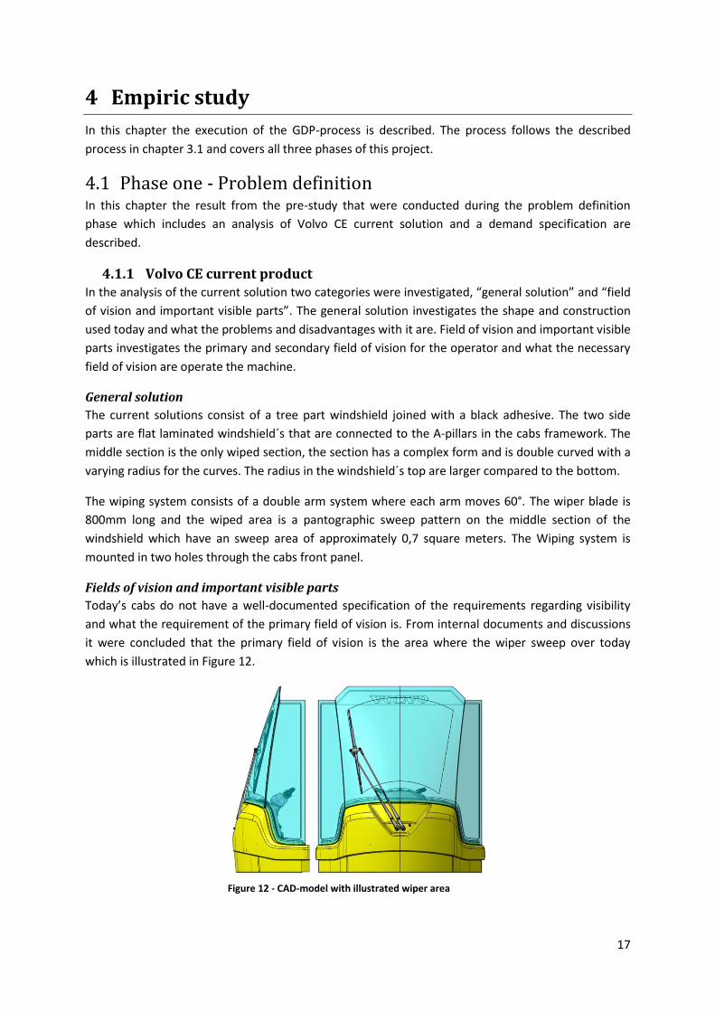
Fields of vision and important visible parts
Today’s cabs do not have a well-documented specification of the requirements regarding visibility
and what the requirement of the primary field of vision is. From internal documents and discussions
it were concluded that the primary field of vision is the area where the wiper sweep over today
which is illustrated in Figure 12.
Figure 12 - CAD-model with illustrated wiper area
18
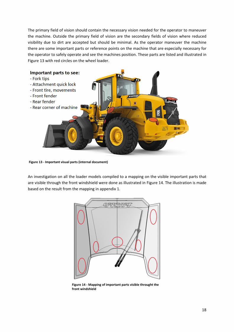
The primary field of vision should contain the necessary vision needed for the operator to maneuver
the machine. Outside the primary field of vision are the secondary fields of vision where reduced
visibility due to dirt are accepted but should be minimal. As the operator maneuver the machine
there are some important parts or reference points on the machine that are especially necessary for
the operator to safely operate and see the machines position. These parts are listed and illustrated in
Figure 13 with red circles on the wheel loader.
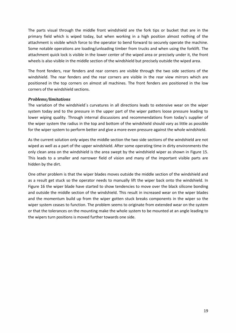
An investigation on all the loader models compiled to a mapping on the visible important parts that
are visible through the front windshield were done as illustrated in Figure 14. The illustration is made
based on the result from the mapping in appendix 1.
Figure 13 - Important visual parts (internal document)
Figure 14 - Mapping of important parts visible throught the front windshield
19
The parts visual through the middle front windshield are the fork tips or bucket that are in the
primary field which is wiped today, but when working in a high position almost nothing of the
attachment is visible which force to the operator to bend forward to securely operate the machine.
Some notable operations are loading/unloading timber from trucks and when using the forklift. The
attachment quick lock is visible in the lower center of the wiped area or precisely under it, the front
wheels is also visible in the middle section of the windshield but precisely outside the wiped area.
The front fenders, rear fenders and rear corners are visible through the two side sections of the
windshield. The rear fenders and the rear corners are visible in the rear view mirrors which are
positioned in the top corners on almost all machines. The front fenders are positioned in the low
corners of the windshield sections.
Problems/limitations
The variation of the windshield´s curvatures in all directions leads to extensive wear on the wiper
system today and to the pressure in the upper part of the wiper patters loose pressure leading to
lower wiping quality. Through internal discussions and recommendations from today’s supplier of
the wiper system the radius in the top and bottom of the windshield should vary as little as possible
for the wiper system to perform better and give a more even pressure against the whole windshield.
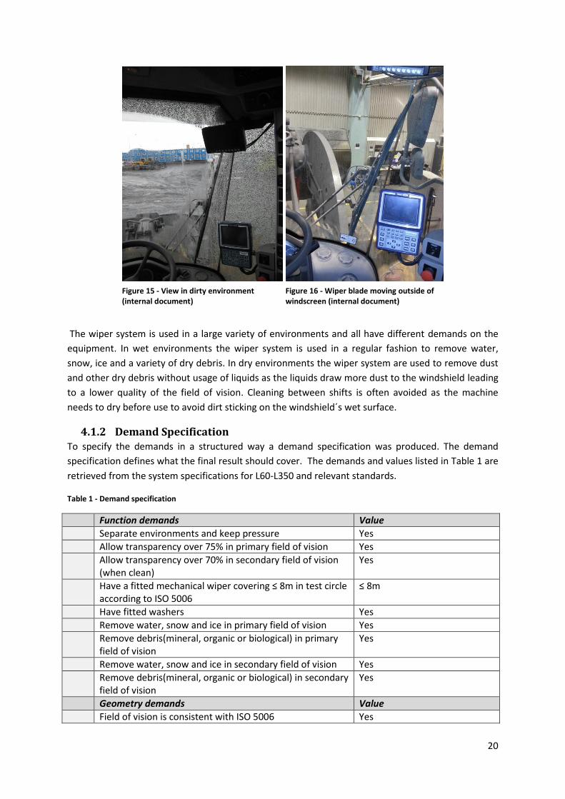
As the current solution only wipes the middle section the two side sections of the windshield are not
wiped as well as a part of the upper windshield. After some operating time in dirty environments the
only clean area on the windshield is the area swept by the windshield wiper as shown in Figure 15.
This leads to a smaller and narrower field of vision and many of the important visible parts are
hidden by the dirt.
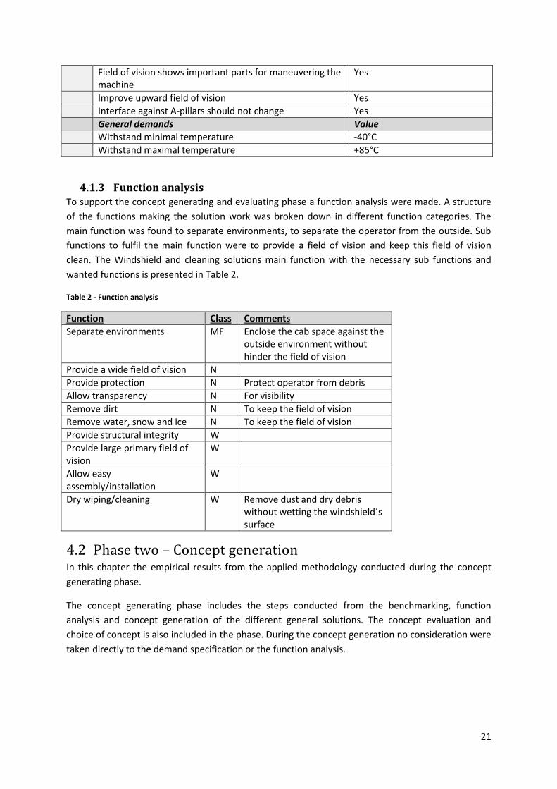
One other problem is that the wiper blades moves outside the middle section of the windshield and
as a result get stuck so the operator needs to manually lift the wiper back onto the windshield. In
Figure 16 the wiper blade have started to show tendencies to move over the black silicone bonding
and outside the middle section of the windshield. This result in increased wear on the wiper blades
and the momentum build up from the wiper gotten stuck breaks components in the wiper so the
wiper system ceases to function. The problem seems to originate from extended wear on the system
or that the tolerances on the mounting make the whole system to be mounted at an angle leading to
the wipers turn positions is moved further towards one side.
20
The wiper system is used in a large variety of environments and all have different demands on the
equipment. In wet environments the wiper system is used in a regular fashion to remove water,
snow, ice and a variety of dry debris. In dry environments the wiper system are used to remove dust
and other dry debris without usage of liquids as the liquids draw more dust to the windshield leading
to a lower quality of the field of vision. Cleaning between shifts is often avoided as the machine
needs to dry before use to avoid dirt sticking on the windshield´s wet surface.
4.1.2 Demand Specification To specify the demands in a structured way a demand specification was produced. The demand
specification defines what the final result should cover. The demands and values listed in Table 1 are
retrieved from the system specifications for L60-L350 and relevant standards.
Table 1 - Demand specification
Function demands Value
Separate environments and keep pressure Yes
Allow transparency over 75% in primary field of vision Yes
Allow transparency over 70% in secondary field of vision (when clean)
Yes
Have a fitted mechanical wiper covering ≤ 8m in test circle according to ISO 5006
≤ 8m
Have fitted washers Yes
Remove water, snow and ice in primary field of vision Yes
Remove debris(mineral, organic or biological) in primary field of vision
Yes
Remove water, snow and ice in secondary field of vision Yes
Remove debris(mineral, organic or biological) in secondary field of vision
Yes
Geometry demands Value
Field of vision is consistent with ISO 5006 Yes
Figure 15 - View in dirty environment (internal document)
Figure 16 - Wiper blade moving outside of windscreen (internal document)
21
Field of vision shows important parts for maneuvering the machine
Yes
Improve upward field of vision Yes
Interface against A-pillars should not change Yes
General demands Value
Withstand minimal temperature -40°C
Withstand maximal temperature +85°C
4.1.3 Function analysis To support the concept generating and evaluating phase a function analysis were made. A structure
of the functions making the solution work was broken down in different function categories. The
main function was found to separate environments, to separate the operator from the outside. Sub
functions to fulfil the main function were to provide a field of vision and keep this field of vision
clean. The Windshield and cleaning solutions main function with the necessary sub functions and
wanted functions is presented in Table 2.
Table 2 - Function analysis
Function Class Comments
Separate environments MF Enclose the cab space against the outside environment without hinder the field of vision
Provide a wide field of vision N
Provide protection N Protect operator from debris
Allow transparency N For visibility
Remove dirt N To keep the field of vision
Remove water, snow and ice N To keep the field of vision
Provide structural integrity W
Provide large primary field of vision
W
Allow easy assembly/installation
W
Dry wiping/cleaning W Remove dust and dry debris without wetting the windshield´s surface
4.2 Phase two – Concept generation In this chapter the empirical results from the applied methodology conducted during the concept
generating phase.
The concept generating phase includes the steps conducted from the benchmarking, function
analysis and concept generation of the different general solutions. The concept evaluation and
choice of concept is also included in the phase. During the concept generation no consideration were
taken directly to the demand specification or the function analysis.
22
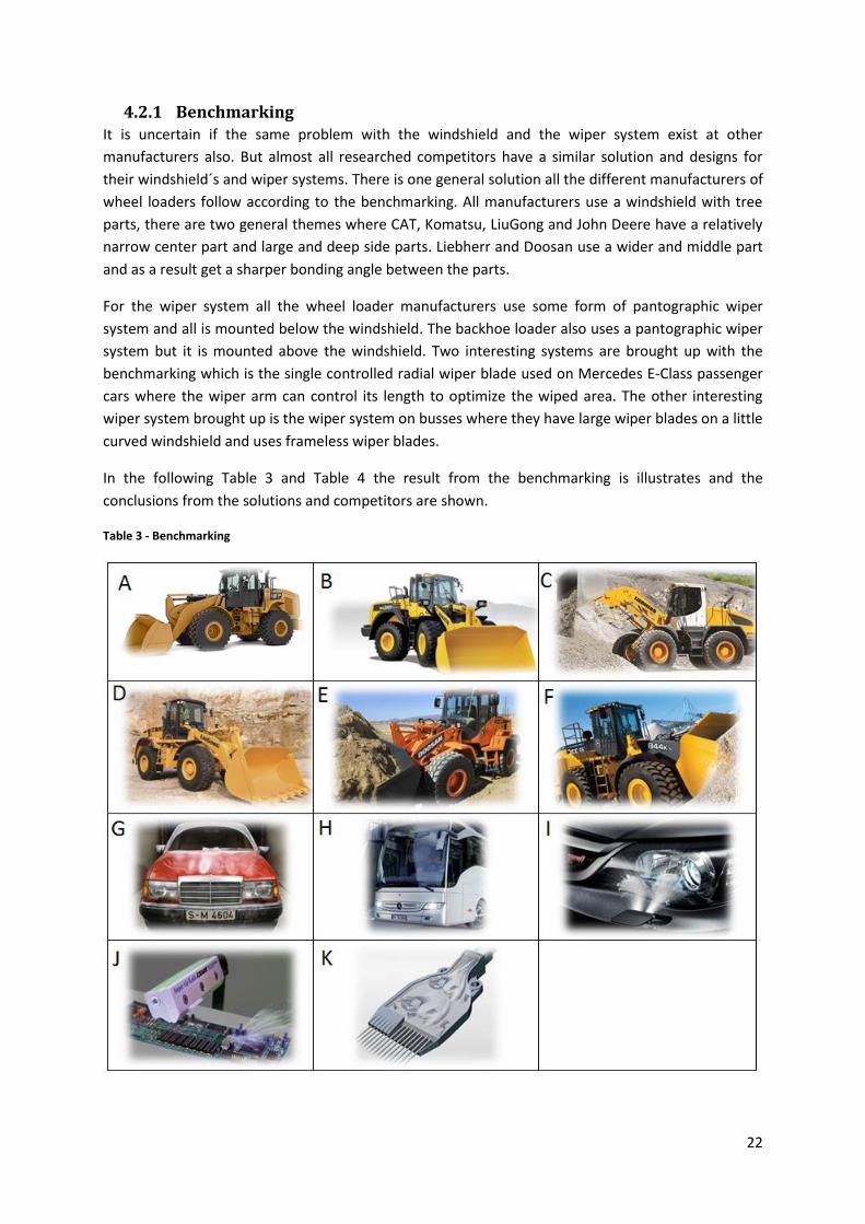
4.2.1 Benchmarking It is uncertain if the same problem with the windshield and the wiper system exist at other
manufacturers also. But almost all researched competitors have a similar solution and designs for
their windshield´s and wiper systems. There is one general solution all the different manufacturers of
wheel loaders follow according to the benchmarking. All manufacturers use a windshield with tree
parts, there are two general themes where CAT, Komatsu, LiuGong and John Deere have a relatively
narrow center part and large and deep side parts. Liebherr and Doosan use a wider and middle part
and as a result get a sharper bonding angle between the parts.
For the wiper system all the wheel loader manufacturers use some form of pantographic wiper
system and all is mounted below the windshield. The backhoe loader also uses a pantographic wiper
system but it is mounted above the windshield. Two interesting systems are brought up with the
benchmarking which is the single controlled radial wiper blade used on Mercedes E-Class passenger
cars where the wiper arm can control its length to optimize the wiped area. The other interesting
wiper system brought up is the wiper system on busses where they have large wiper blades on a little
curved windshield and uses frameless wiper blades.
In the following Table 3 and Table 4 the result from the benchmarking is illustrates and the
conclusions from the solutions and competitors are shown.
Table 3 - Benchmarking
23
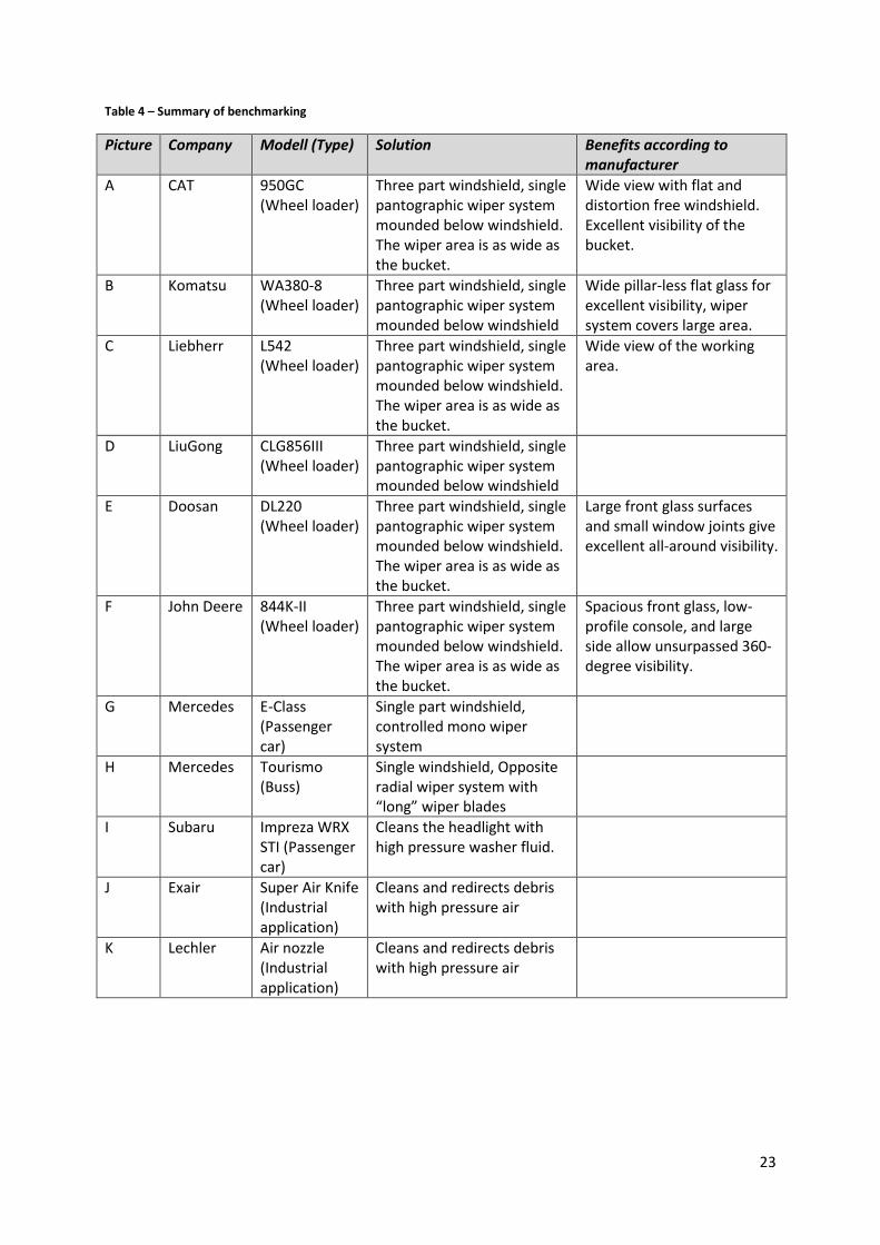
Table 4 – Summary of benchmarking
Picture Company Modell (Type) Solution Benefits according to manufacturer
A CAT 950GC (Wheel loader)
Three part windshield, single pantographic wiper system mounded below windshield. The wiper area is as wide as the bucket.
Wide view with flat and distortion free windshield. Excellent visibility of the bucket.
B Komatsu WA380-8 (Wheel loader)
Three part windshield, single pantographic wiper system mounded below windshield
Wide pillar-less flat glass for excellent visibility, wiper system covers large area.
C Liebherr L542 (Wheel loader)
Three part windshield, single pantographic wiper system mounded below windshield. The wiper area is as wide as the bucket.
Wide view of the working area.
D LiuGong CLG856III (Wheel loader)
Three part windshield, single pantographic wiper system mounded below windshield
E Doosan DL220 (Wheel loader)
Three part windshield, single pantographic wiper system mounded below windshield. The wiper area is as wide as the bucket.
Large front glass surfaces and small window joints give excellent all-around visibility.
F John Deere 844K-II (Wheel loader)
Three part windshield, single pantographic wiper system mounded below windshield. The wiper area is as wide as the bucket.
Spacious front glass, low-profile console, and large side allow unsurpassed 360-degree visibility.
G Mercedes E-Class (Passenger car)
Single part windshield, controlled mono wiper system
H Mercedes Tourismo (Buss)
Single windshield, Opposite radial wiper system with “long” wiper blades
I Subaru Impreza WRX STI (Passenger car)
Cleans the headlight with high pressure washer fluid.
J Exair Super Air Knife (Industrial application)
Cleans and redirects debris with high pressure air
K Lechler Air nozzle (Industrial application)
Cleans and redirects debris with high pressure air
24
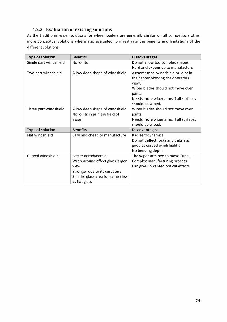
4.2.2 Evaluation of existing solutions As the traditional wiper solutions for wheel loaders are generally similar on all competitors other
more conceptual solutions where also evaluated to investigate the benefits and limitations of the
different solutions.
Type of solution Benefits Disadvantages
Single part windshield No joints Do not allow too complex shapes Hard and expensive to manufacture
Two part windshield Allow deep shape of windshield Asymmetrical windshield or joint in the center blocking the operators view. Wiper blades should not move over joints. Needs more wiper arms if all surfaces should be wiped.
Three part windshield Allow deep shape of windshield No joints in primary field of vision
Wiper blades should not move over joints. Needs more wiper arms if all surfaces should be wiped.
Type of solution Benefits Disadvantages
Flat windshield Easy and cheap to manufacture Bad aerodynamics Do not deflect rocks and debris as good as curved windshield´s No bending depth
Curved windshield Better aerodynamic Wrap-around effect gives larger view Stronger due to its curvature Smaller glass area for same view as flat glass
The wiper arm ned to move “uphill” Complex manufacturing process Can give unwanted optical effects
25
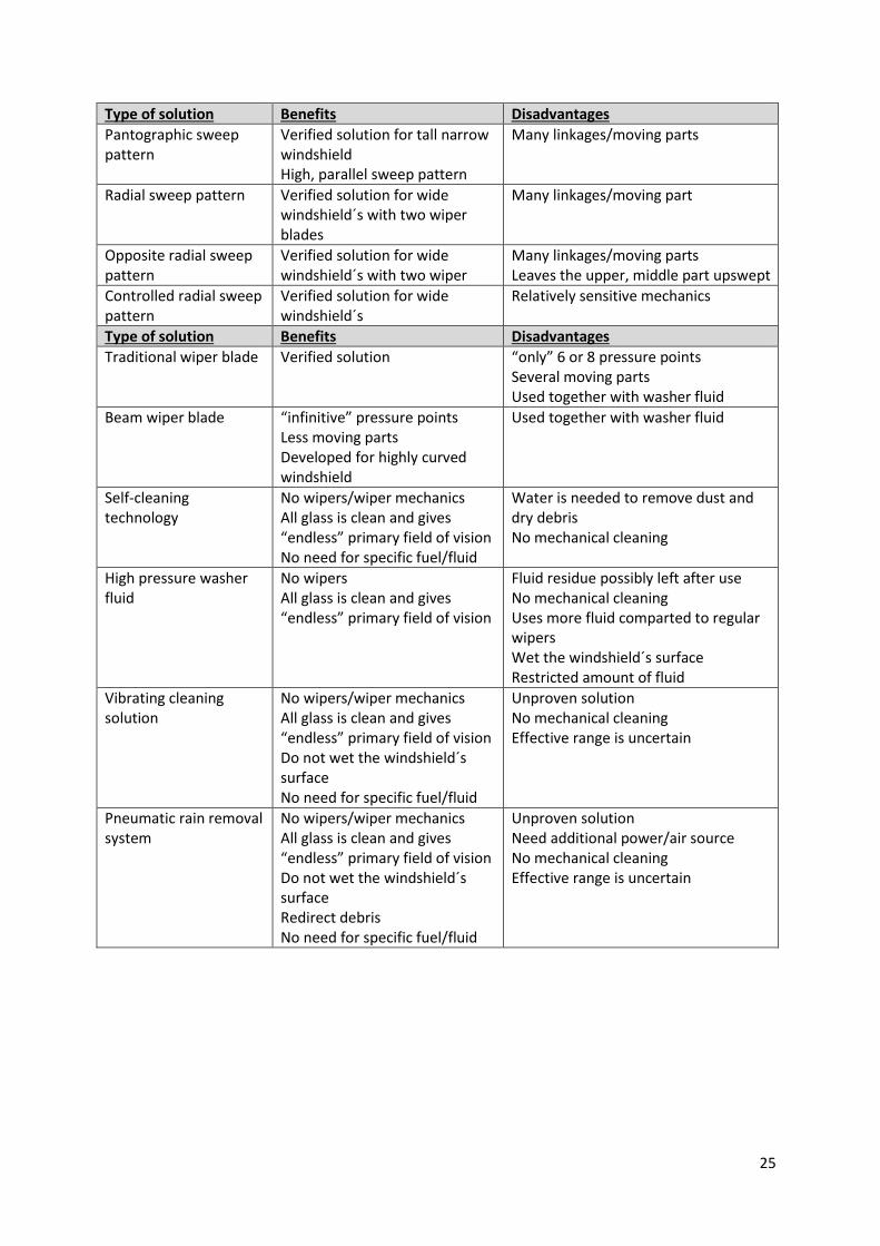
Type of solution Benefits Disadvantages
Pantographic sweep pattern
Verified solution for tall narrow windshield High, parallel sweep pattern
Many linkages/moving parts
Radial sweep pattern Verified solution for wide windshield´s with two wiper blades
Many linkages/moving part
Opposite radial sweep pattern
Verified solution for wide windshield´s with two wiper
Many linkages/moving parts Leaves the upper, middle part upswept
Controlled radial sweep pattern
Verified solution for wide windshield´s
Relatively sensitive mechanics
Type of solution Benefits Disadvantages
Traditional wiper blade Verified solution “only” 6 or 8 pressure points Several moving parts Used together with washer fluid
Beam wiper blade “infinitive” pressure points Less moving parts Developed for highly curved windshield
Used together with washer fluid
Self-cleaning technology
No wipers/wiper mechanics All glass is clean and gives “endless” primary field of vision No need for specific fuel/fluid
Water is needed to remove dust and dry debris No mechanical cleaning
High pressure washer fluid
No wipers All glass is clean and gives “endless” primary field of vision
Fluid residue possibly left after use No mechanical cleaning Uses more fluid comparted to regular wipers Wet the windshield´s surface Restricted amount of fluid
Vibrating cleaning solution
No wipers/wiper mechanics All glass is clean and gives “endless” primary field of vision Do not wet the windshield´s surface No need for specific fuel/fluid
Unproven solution No mechanical cleaning Effective range is uncertain
Pneumatic rain removal system
No wipers/wiper mechanics All glass is clean and gives “endless” primary field of vision Do not wet the windshield´s surface Redirect debris No need for specific fuel/fluid
Unproven solution Need additional power/air source No mechanical cleaning Effective range is uncertain
26
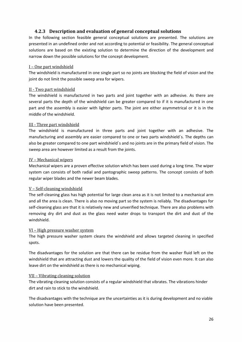
4.2.3 Description and evaluation of general conceptual solutions In the following section feasible general conceptual solutions are presented. The solutions are
presented in an undefined order and not according to potential or feasibility. The general conceptual
solutions are based on the existing solution to determine the direction of the development and
narrow down the possible solutions for the concept development.
I – One part windshield
The windshield is manufactured in one single part so no joints are blocking the field of vision and the
joint do not limit the possible sweep area for wipers.
II - Two part windshield
The windshield is manufactured in two parts and joint together with an adhesive. As there are
several parts the depth of the windshield can be greater compared to if it is manufactured in one
part and the assembly is easier with lighter parts. The joint are either asymmetrical or it is in the
middle of the windshield.
III - Three part windshield
The windshield is manufactured in three parts and joint together with an adhesive. The
manufacturing and assembly are easier compared to one or two parts windshield´s. The depths can
also be greater compared to one part windshield´s and no joints are in the primary field of vision. The
sweep area are however limited as a result from the joints.
IV – Mechanical wipers
Mechanical wipers are a proven effective solution which has been used during a long time. The wiper
system can consists of both radial and pantographic sweep patterns. The concept consists of both
regular wiper blades and the newer beam blades.
V – Self-cleaning windshield
The self-cleaning glass has high potential for large clean area as it is not limited to a mechanical arm
and all the area is clean. There is also no moving part so the system is reliably. The disadvantages for
self-cleaning glass are that it is relatively new and unverified technique. There are also problems with
removing dry dirt and dust as the glass need water drops to transport the dirt and dust of the
windshield.
VI – High pressure washer system
The high pressure washer system cleans the windshield and allows targeted cleaning in specified
spots.
The disadvantages for the solution are that there can be residue from the washer fluid left on the
windshield that are attracting dust and lowers the quality of the field of vision even more. It can also
leave dirt on the windshield as there is no mechanical wiping.
VII – Vibrating cleaning solution
The vibrating cleaning solution consists of a regular windshield that vibrates. The vibrations hinder
dirt and rain to stick to the windshield.
The disadvantages with the technique are the uncertainties as it is during development and no viable
solution have been presented.
27
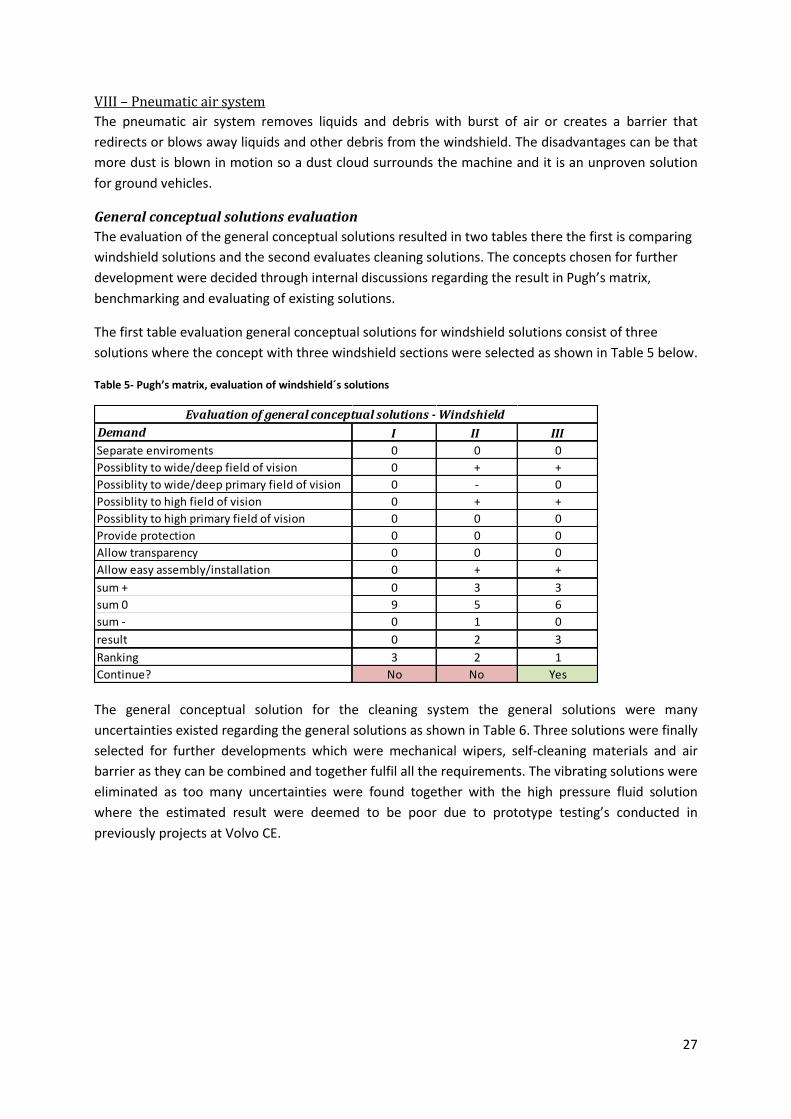
VIII – Pneumatic air system
The pneumatic air system removes liquids and debris with burst of air or creates a barrier that
redirects or blows away liquids and other debris from the windshield. The disadvantages can be that
more dust is blown in motion so a dust cloud surrounds the machine and it is an unproven solution
for ground vehicles.
General conceptual solutions evaluation
The evaluation of the general conceptual solutions resulted in two tables there the first is comparing
windshield solutions and the second evaluates cleaning solutions. The concepts chosen for further
development were decided through internal discussions regarding the result in Pugh’s matrix,
benchmarking and evaluating of existing solutions.
The first table evaluation general conceptual solutions for windshield solutions consist of three
solutions where the concept with three windshield sections were selected as shown in Table 5 below.
Table 5- Pugh’s matrix, evaluation of windshield´s solutions
The general conceptual solution for the cleaning system the general solutions were many
uncertainties existed regarding the general solutions as shown in Table 6. Three solutions were finally
selected for further developments which were mechanical wipers, self-cleaning materials and air
barrier as they can be combined and together fulfil all the requirements. The vibrating solutions were
eliminated as too many uncertainties were found together with the high pressure fluid solution
where the estimated result were deemed to be poor due to prototype testing’s conducted in
previously projects at Volvo CE.
Demand I II III
Separate enviroments 0 0 0
Possiblity to wide/deep field of vision 0 + +
Possiblity to wide/deep primary field of vision 0 - 0
Possiblity to high field of vision 0 + +
Possiblity to high primary field of vision 0 0 0
Provide protection 0 0 0
Allow transparency 0 0 0
Allow easy assembly/installation 0 + +
sum + 0 3 3
sum 0 9 5 6
sum - 0 1 0
result 0 2 3
Ranking 3 2 1
Continue? No No Yes
Evaluation of general conceptual solutions - Windshield
28
Figure 17 - Concept 1
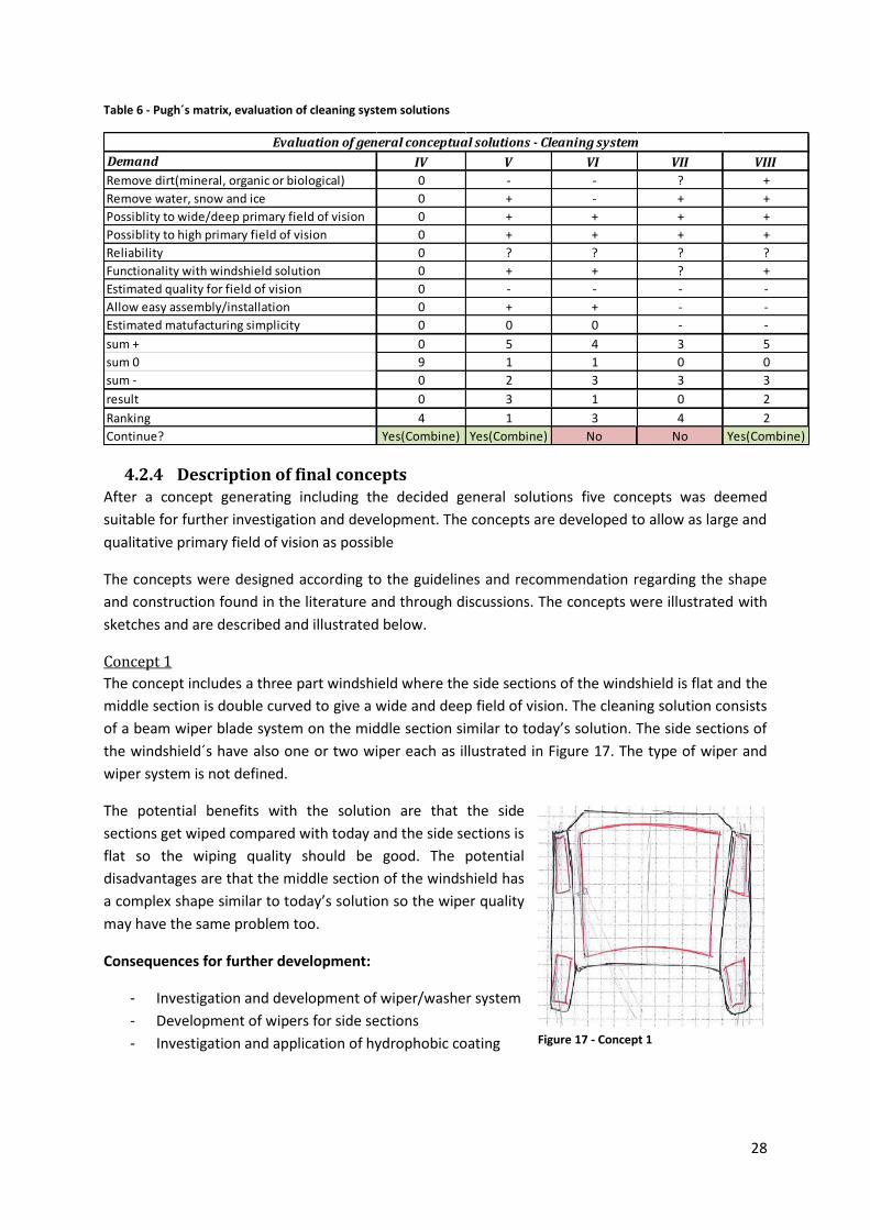
Table 6 - Pugh´s matrix, evaluation of cleaning system solutions
4.2.4 Description of final concepts After a concept generating including the decided general solutions five concepts was deemed
suitable for further investigation and development. The concepts are developed to allow as large and
qualitative primary field of vision as possible
The concepts were designed according to the guidelines and recommendation regarding the shape
and construction found in the literature and through discussions. The concepts were illustrated with
sketches and are described and illustrated below.
Concept 1
The concept includes a three part windshield where the side sections of the windshield is flat and the
middle section is double curved to give a wide and deep field of vision. The cleaning solution consists
of a beam wiper blade system on the middle section similar to today’s solution. The side sections of
the windshield´s have also one or two wiper each as illustrated in Figure 17. The type of wiper and
wiper system is not defined.
The potential benefits with the solution are that the side
sections get wiped compared with today and the side sections is
flat so the wiping quality should be good. The potential
disadvantages are that the middle section of the windshield has
a complex shape similar to today’s solution so the wiper quality
may have the same problem too.
Consequences for further development:
- Investigation and development of wiper/washer system
- Development of wipers for side sections
- Investigation and application of hydrophobic coating
Demand IV V VI VII VIII
Remove dirt(mineral, organic or biological) 0 - - ? +
Remove water, snow and ice 0 + - + +
Possiblity to wide/deep primary field of vision 0 + + + +
Possiblity to high primary field of vision 0 + + + +
Reliability 0 ? ? ? ?
Functionality with windshield solution 0 + + ? +
Estimated quality for field of vision 0 - - - -
Allow easy assembly/installation 0 + + - -
Estimated matufacturing simplicity 0 0 0 - -
sum + 0 5 4 3 5
sum 0 9 1 1 0 0
sum - 0 2 3 3 3
result 0 3 1 0 2
Ranking 4 1 3 4 2
Continue? Yes(Combine) Yes(Combine) No No Yes(Combine)
Evaluation of general conceptual solutions - Cleaning system
29
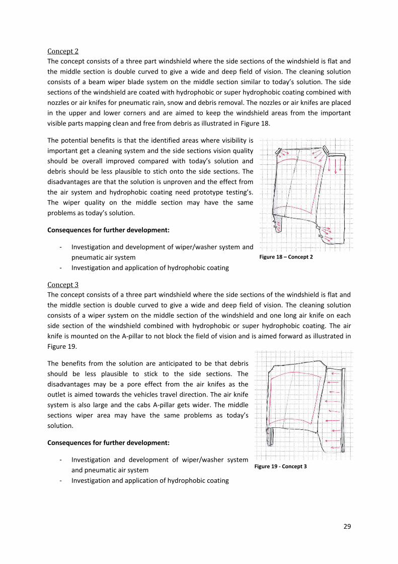
Concept 2
The concept consists of a three part windshield where the side sections of the windshield is flat and
the middle section is double curved to give a wide and deep field of vision. The cleaning solution
consists of a beam wiper blade system on the middle section similar to today’s solution. The side
sections of the windshield are coated with hydrophobic or super hydrophobic coating combined with
nozzles or air knifes for pneumatic rain, snow and debris removal. The nozzles or air knifes are placed
in the upper and lower corners and are aimed to keep the windshield areas from the important
visible parts mapping clean and free from debris as illustrated in Figure 18.
The potential benefits is that the identified areas where visibility is
important get a cleaning system and the side sections vision quality
should be overall improved compared with today’s solution and
debris should be less plausible to stich onto the side sections. The
disadvantages are that the solution is unproven and the effect from
the air system and hydrophobic coating need prototype testing’s.
The wiper quality on the middle section may have the same
problems as today’s solution.
Consequences for further development:
- Investigation and development of wiper/washer system and
pneumatic air system
- Investigation and application of hydrophobic coating
Concept 3
The concept consists of a three part windshield where the side sections of the windshield is flat and
the middle section is double curved to give a wide and deep field of vision. The cleaning solution
consists of a wiper system on the middle section of the windshield and one long air knife on each
side section of the windshield combined with hydrophobic or super hydrophobic coating. The air
knife is mounted on the A-pillar to not block the field of vision and is aimed forward as illustrated in
Figure 19.
The benefits from the solution are anticipated to be that debris
should be less plausible to stick to the side sections. The
disadvantages may be a pore effect from the air knifes as the
outlet is aimed towards the vehicles travel direction. The air knife
system is also large and the cabs A-pillar gets wider. The middle
sections wiper area may have the same problems as today’s
solution.
Consequences for further development:
- Investigation and development of wiper/washer system
and pneumatic air system
- Investigation and application of hydrophobic coating
Figure 18 – Concept 2
Figure 19 - Concept 3
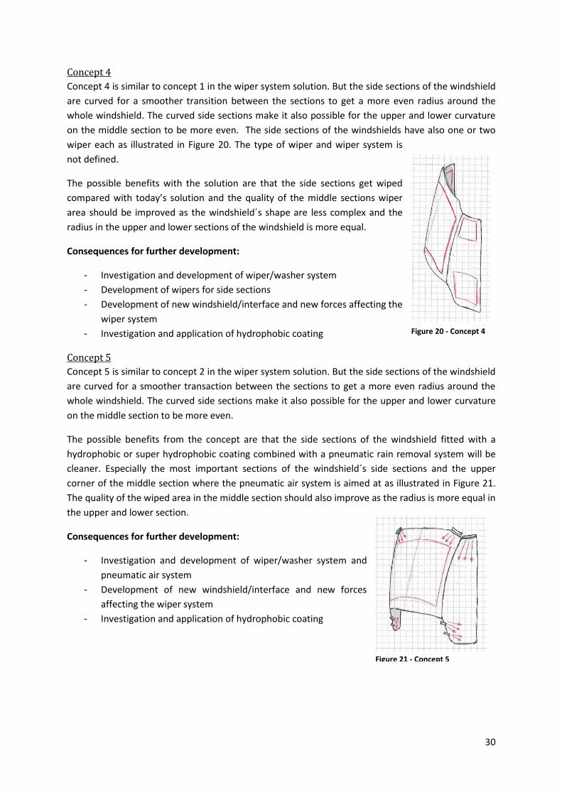
30
Concept 4
Concept 4 is similar to concept 1 in the wiper system solution. But the side sections of the windshield
are curved for a smoother transition between the sections to get a more even radius around the
whole windshield. The curved side sections make it also possible for the upper and lower curvature
on the middle section to be more even. The side sections of the windshields have also one or two
wiper each as illustrated in Figure 20. The type of wiper and wiper system is
not defined.
The possible benefits with the solution are that the side sections get wiped
compared with today’s solution and the quality of the middle sections wiper
area should be improved as the windshield´s shape are less complex and the
radius in the upper and lower sections of the windshield is more equal.
Consequences for further development:
- Investigation and development of wiper/washer system
- Development of wipers for side sections
- Development of new windshield/interface and new forces affecting the
wiper system
- Investigation and application of hydrophobic coating
Concept 5
Concept 5 is similar to concept 2 in the wiper system solution. But the side sections of the windshield
are curved for a smoother transaction between the sections to get a more even radius around the
whole windshield. The curved side sections make it also possible for the upper and lower curvature
on the middle section to be more even.
The possible benefits from the concept are that the side sections of the windshield fitted with a
hydrophobic or super hydrophobic coating combined with a pneumatic rain removal system will be
cleaner. Especially the most important sections of the windshield´s side sections and the upper
corner of the middle section where the pneumatic air system is aimed at as illustrated in Figure 21.
The quality of the wiped area in the middle section should also improve as the radius is more equal in
the upper and lower section.
Consequences for further development:
- Investigation and development of wiper/washer system and
pneumatic air system
- Development of new windshield/interface and new forces
affecting the wiper system
- Investigation and application of hydrophobic coating
Figure 20 - Concept 4
Figure 21 - Concept 5
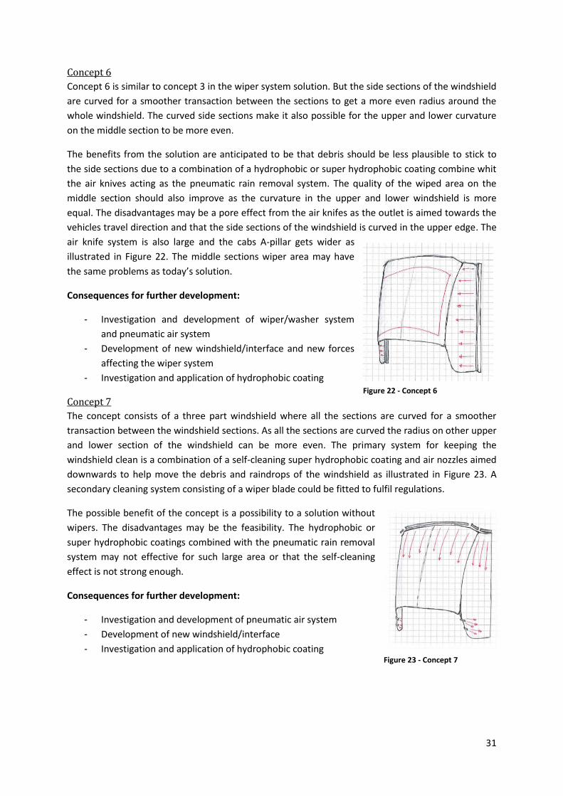
31
Concept 6
Concept 6 is similar to concept 3 in the wiper system solution. But the side sections of the windshield
are curved for a smoother transaction between the sections to get a more even radius around the
whole windshield. The curved side sections make it also possible for the upper and lower curvature
on the middle section to be more even.
The benefits from the solution are anticipated to be that debris should be less plausible to stick to
the side sections due to a combination of a hydrophobic or super hydrophobic coating combine whit
the air knives acting as the pneumatic rain removal system. The quality of the wiped area on the
middle section should also improve as the curvature in the upper and lower windshield is more
equal. The disadvantages may be a pore effect from the air knifes as the outlet is aimed towards the
vehicles travel direction and that the side sections of the windshield is curved in the upper edge. The
air knife system is also large and the cabs A-pillar gets wider as
illustrated in Figure 22. The middle sections wiper area may have
the same problems as today’s solution.
Consequences for further development:
- Investigation and development of wiper/washer system
and pneumatic air system
- Development of new windshield/interface and new forces
affecting the wiper system
- Investigation and application of hydrophobic coating
Concept 7
The concept consists of a three part windshield where all the sections are curved for a smoother
transaction between the windshield sections. As all the sections are curved the radius on other upper
and lower section of the windshield can be more even. The primary system for keeping the
windshield clean is a combination of a self-cleaning super hydrophobic coating and air nozzles aimed
downwards to help move the debris and raindrops of the windshield as illustrated in Figure 23. A
secondary cleaning system consisting of a wiper blade could be fitted to fulfil regulations.
The possible benefit of the concept is a possibility to a solution without
wipers. The disadvantages may be the feasibility. The hydrophobic or
super hydrophobic coatings combined with the pneumatic rain removal
system may not effective for such large area or that the self-cleaning
effect is not strong enough.
Consequences for further development:
- Investigation and development of pneumatic air system
- Development of new windshield/interface
- Investigation and application of hydrophobic coating
Figure 22 - Concept 6
Figure 23 - Concept 7
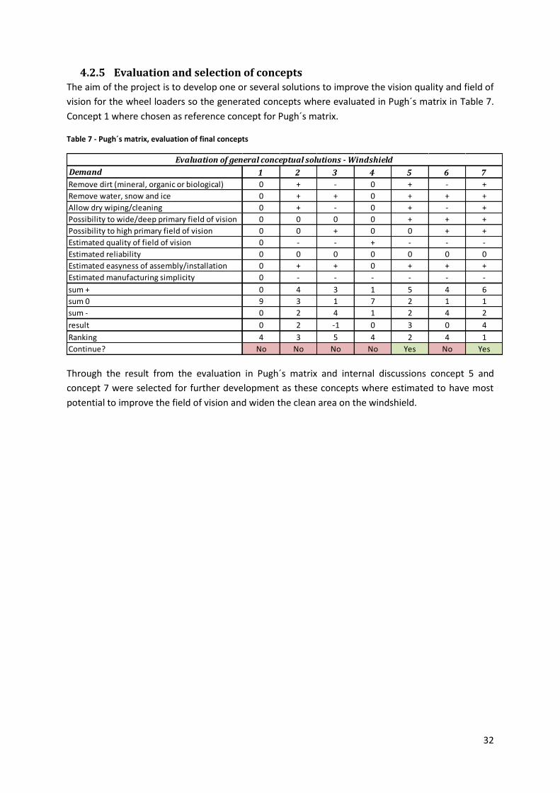
32
4.2.5 Evaluation and selection of concepts The aim of the project is to develop one or several solutions to improve the vision quality and field of
vision for the wheel loaders so the generated concepts where evaluated in Pugh´s matrix in Table 7.
Concept 1 where chosen as reference concept for Pugh´s matrix.
Table 7 - Pugh´s matrix, evaluation of final concepts
Through the result from the evaluation in Pugh´s matrix and internal discussions concept 5 and
concept 7 were selected for further development as these concepts where estimated to have most
potential to improve the field of vision and widen the clean area on the windshield.
Demand 1 2 3 4 5 6 7
Remove dirt (mineral, organic or biological) 0 + - 0 + - +
Remove water, snow and ice 0 + + 0 + + +
Allow dry wiping/cleaning 0 + - 0 + - +
Possibility to wide/deep primary field of vision 0 0 0 0 + + +
Possibility to high primary field of vision 0 0 + 0 0 + +
Estimated quality of field of vision 0 - - + - - -
Estimated reliability 0 0 0 0 0 0 0
Estimated easyness of assembly/installation 0 + + 0 + + +
Estimated manufacturing simplicity 0 - - - - - -
sum + 0 4 3 1 5 4 6
sum 0 9 3 1 7 2 1 1
sum - 0 2 4 1 2 4 2
result 0 2 -1 0 3 0 4
Ranking 4 3 5 4 2 4 1
Continue? No No No No Yes No Yes
Evaluation of general conceptual solutions - Windshield
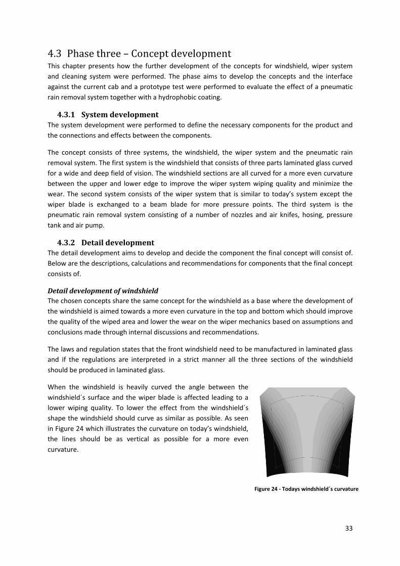
33
4.3 Phase three – Concept development This chapter presents how the further development of the concepts for windshield, wiper system
and cleaning system were performed. The phase aims to develop the concepts and the interface
against the current cab and a prototype test were performed to evaluate the effect of a pneumatic
rain removal system together with a hydrophobic coating.
4.3.1 System development The system development were performed to define the necessary components for the product and
the connections and effects between the components.
The concept consists of three systems, the windshield, the wiper system and the pneumatic rain
removal system. The first system is the windshield that consists of three parts laminated glass curved
for a wide and deep field of vision. The windshield sections are all curved for a more even curvature
between the upper and lower edge to improve the wiper system wiping quality and minimize the
wear. The second system consists of the wiper system that is similar to today’s system except the
wiper blade is exchanged to a beam blade for more pressure points. The third system is the
pneumatic rain removal system consisting of a number of nozzles and air knifes, hosing, pressure
tank and air pump.
4.3.2 Detail development The detail development aims to develop and decide the component the final concept will consist of.
Below are the descriptions, calculations and recommendations for components that the final concept
consists of.
Detail development of windshield
The chosen concepts share the same concept for the windshield as a base where the development of
the windshield is aimed towards a more even curvature in the top and bottom which should improve
the quality of the wiped area and lower the wear on the wiper mechanics based on assumptions and
conclusions made through internal discussions and recommendations.
The laws and regulation states that the front windshield need to be manufactured in laminated glass
and if the regulations are interpreted in a strict manner all the three sections of the windshield
should be produced in laminated glass.
When the windshield is heavily curved the angle between the
windshield´s surface and the wiper blade is affected leading to a
lower wiping quality. To lower the effect from the windshield´s
shape the windshield should curve as similar as possible. As seen
in Figure 24 which illustrates the curvature on today’s windshield,
the lines should be as vertical as possible for a more even
curvature.
Figure 24 - Todays windshield´s curvature
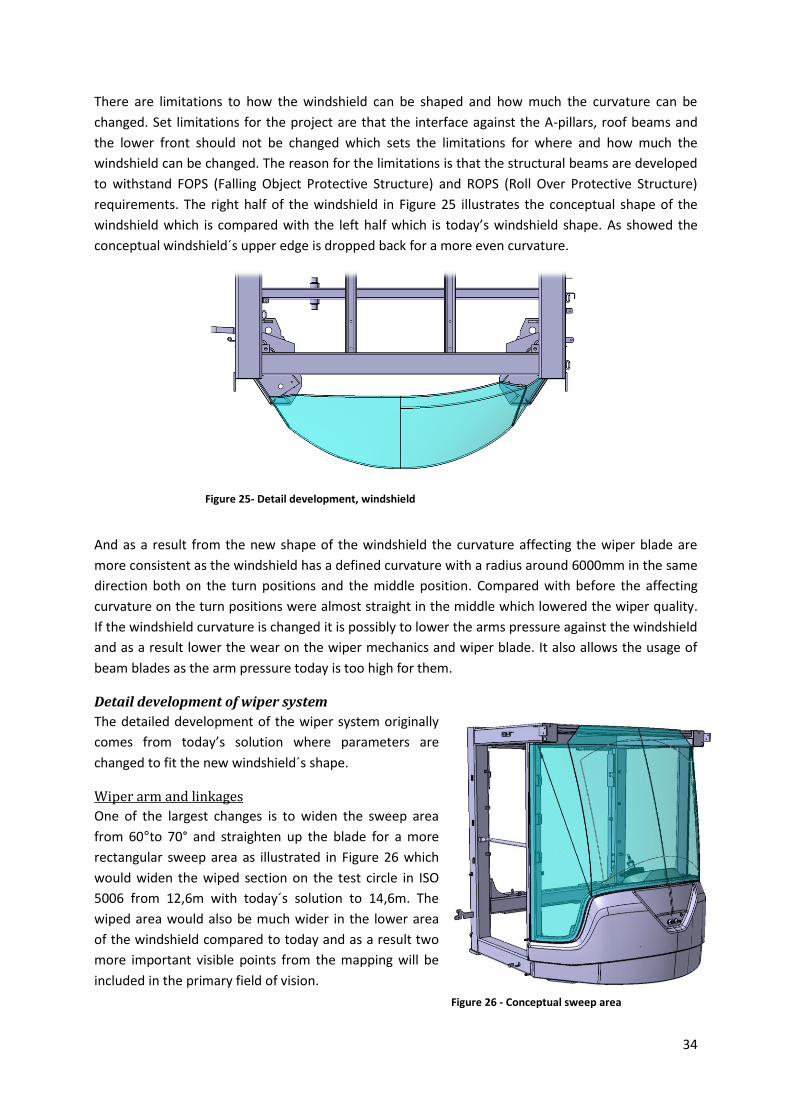
34
There are limitations to how the windshield can be shaped and how much the curvature can be
changed. Set limitations for the project are that the interface against the A-pillars, roof beams and
the lower front should not be changed which sets the limitations for where and how much the
windshield can be changed. The reason for the limitations is that the structural beams are developed
to withstand FOPS (Falling Object Protective Structure) and ROPS (Roll Over Protective Structure)
requirements. The right half of the windshield in Figure 25 illustrates the conceptual shape of the
windshield which is compared with the left half which is today’s windshield shape. As showed the
conceptual windshield´s upper edge is dropped back for a more even curvature.
And as a result from the new shape of the windshield the curvature affecting the wiper blade are
more consistent as the windshield has a defined curvature with a radius around 6000mm in the same
direction both on the turn positions and the middle position. Compared with before the affecting
curvature on the turn positions were almost straight in the middle which lowered the wiper quality.
If the windshield curvature is changed it is possibly to lower the arms pressure against the windshield
and as a result lower the wear on the wiper mechanics and wiper blade. It also allows the usage of
beam blades as the arm pressure today is too high for them.
Detail development of wiper system
The detailed development of the wiper system originally
comes from today’s solution where parameters are
changed to fit the new windshield´s shape.
Wiper arm and linkages
One of the largest changes is to widen the sweep area
from 60°to 70° and straighten up the blade for a more
rectangular sweep area as illustrated in Figure 26 which
would widen the wiped section on the test circle in ISO
5006 from 12,6m with today´s solution to 14,6m. The
wiped area would also be much wider in the lower area
of the windshield compared to today and as a result two
more important visible points from the mapping will be
included in the primary field of vision.
Figure 25- Detail development, windshield
Figure 26 - Conceptual sweep area
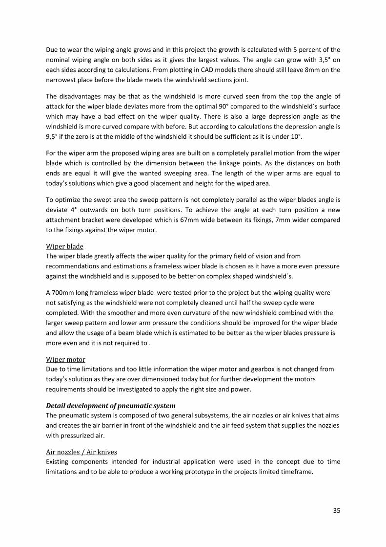
35
Due to wear the wiping angle grows and in this project the growth is calculated with 5 percent of the
nominal wiping angle on both sides as it gives the largest values. The angle can grow with 3,5° on
each sides according to calculations. From plotting in CAD models there should still leave 8mm on the
narrowest place before the blade meets the windshield sections joint.
The disadvantages may be that as the windshield is more curved seen from the top the angle of
attack for the wiper blade deviates more from the optimal 90° compared to the windshield´s surface
which may have a bad effect on the wiper quality. There is also a large depression angle as the
windshield is more curved compare with before. But according to calculations the depression angle is
9,5° if the zero is at the middle of the windshield it should be sufficient as it is under 10°.
For the wiper arm the proposed wiping area are built on a completely parallel motion from the wiper
blade which is controlled by the dimension between the linkage points. As the distances on both
ends are equal it will give the wanted sweeping area. The length of the wiper arms are equal to
today’s solutions which give a good placement and height for the wiped area.
To optimize the swept area the sweep pattern is not completely parallel as the wiper blades angle is
deviate 4° outwards on both turn positions. To achieve the angle at each turn position a new
attachment bracket were developed which is 67mm wide between its fixings, 7mm wider compared
to the fixings against the wiper motor.
Wiper blade
The wiper blade greatly affects the wiper quality for the primary field of vision and from
recommendations and estimations a frameless wiper blade is chosen as it have a more even pressure
against the windshield and is supposed to be better on complex shaped windshield´s.
A 700mm long frameless wiper blade were tested prior to the project but the wiping quality were
not satisfying as the windshield were not completely cleaned until half the sweep cycle were
completed. With the smoother and more even curvature of the new windshield combined with the
larger sweep pattern and lower arm pressure the conditions should be improved for the wiper blade
and allow the usage of a beam blade which is estimated to be better as the wiper blades pressure is
more even and it is not required to .
Wiper motor
Due to time limitations and too little information the wiper motor and gearbox is not changed from
today’s solution as they are over dimensioned today but for further development the motors
requirements should be investigated to apply the right size and power.
Detail development of pneumatic system
The pneumatic system is composed of two general subsystems, the air nozzles or air knives that aims
and creates the air barrier in front of the windshield and the air feed system that supplies the nozzles
with pressurized air.
Air nozzles / Air knives
Existing components intended for industrial application were used in the concept due to time
limitations and to be able to produce a working prototype in the projects limited timeframe.
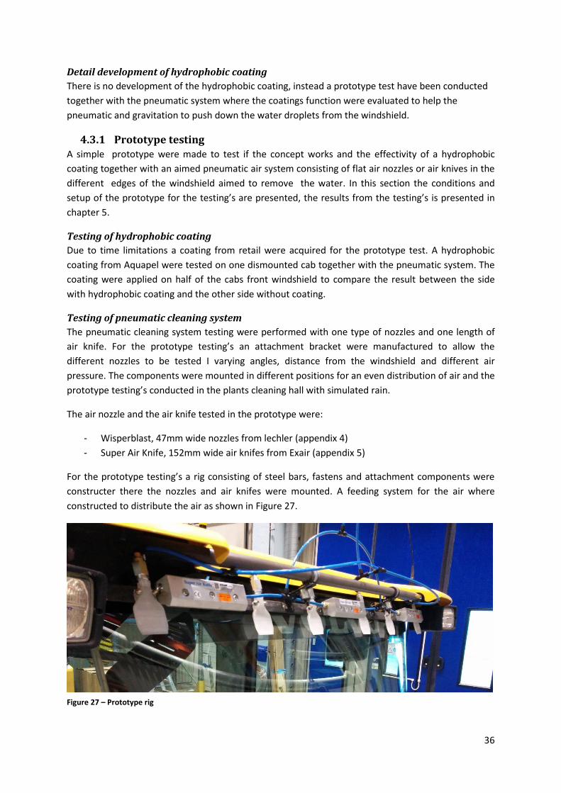
36
Detail development of hydrophobic coating
There is no development of the hydrophobic coating, instead a prototype test have been conducted
together with the pneumatic system where the coatings function were evaluated to help the
pneumatic and gravitation to push down the water droplets from the windshield.
4.3.1 Prototype testing A simple prototype were made to test if the concept works and the effectivity of a hydrophobic
coating together with an aimed pneumatic air system consisting of flat air nozzles or air knives in the
different edges of the windshield aimed to remove the water. In this section the conditions and
setup of the prototype for the testing’s are presented, the results from the testing’s is presented in
chapter 5.
Testing of hydrophobic coating
Due to time limitations a coating from retail were acquired for the prototype test. A hydrophobic
coating from Aquapel were tested on one dismounted cab together with the pneumatic system. The
coating were applied on half of the cabs front windshield to compare the result between the side
with hydrophobic coating and the other side without coating.
Testing of pneumatic cleaning system
The pneumatic cleaning system testing were performed with one type of nozzles and one length of
air knife. For the prototype testing’s an attachment bracket were manufactured to allow the
different nozzles to be tested I varying angles, distance from the windshield and different air
pressure. The components were mounted in different positions for an even distribution of air and the
prototype testing’s conducted in the plants cleaning hall with simulated rain.
The air nozzle and the air knife tested in the prototype were:
- Wisperblast, 47mm wide nozzles from lechler (appendix 4)
- Super Air Knife, 152mm wide air knifes from Exair (appendix 5)
For the prototype testing’s a rig consisting of steel bars, fastens and attachment components were
constructer there the nozzles and air knifes were mounted. A feeding system for the air where
constructed to distribute the air as shown in Figure 27.
Figure 27 – Prototype rig
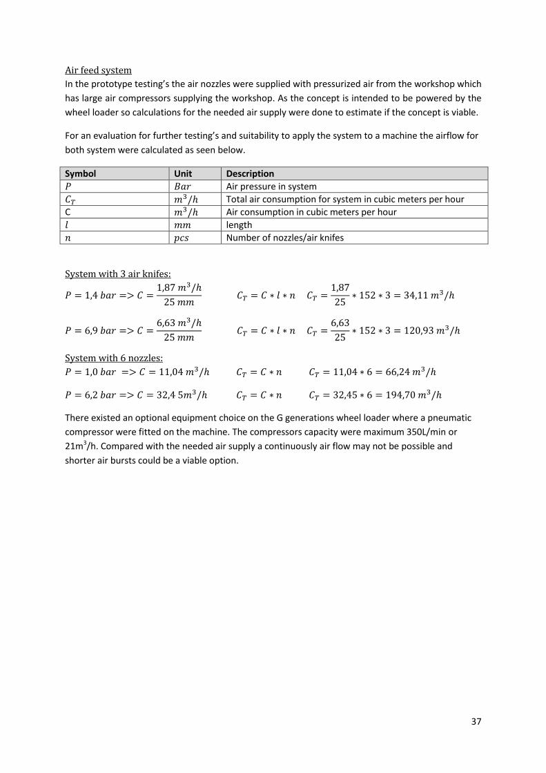
37
Air feed system
In the prototype testing’s the air nozzles were supplied with pressurized air from the workshop which
has large air compressors supplying the workshop. As the concept is intended to be powered by the
wheel loader so calculations for the needed air supply were done to estimate if the concept is viable.
For an evaluation for further testing’s and suitability to apply the system to a machine the airflow for
both system were calculated as seen below.
Symbol Unit Description
𝑃 𝐵𝑎𝑟 Air pressure in system
𝐶𝑇 𝑚3/ℎ Total air consumption for system in cubic meters per hour
C 𝑚3/ℎ Air consumption in cubic meters per hour
𝑙 𝑚𝑚 length
𝑛 𝑝𝑐𝑠 Number of nozzles/air knifes
System with 3 air knifes:
𝑃 = 1,4 𝑏𝑎𝑟 => 𝐶 =1,87 𝑚3/ℎ
25 𝑚𝑚 𝐶𝑇 = 𝐶 ∗ 𝑙 ∗ 𝑛 𝐶𝑇 =
1,87
25∗ 152 ∗ 3 = 34,11 𝑚3/ℎ
𝑃 = 6,9 𝑏𝑎𝑟 => 𝐶 =6,63 𝑚3/ℎ
25 𝑚𝑚 𝐶𝑇 = 𝐶 ∗ 𝑙 ∗ 𝑛 𝐶𝑇 =
6,63
25∗ 152 ∗ 3 = 120,93 𝑚3/ℎ
System with 6 nozzles:
𝑃 = 1,0 𝑏𝑎𝑟 => 𝐶 = 11,04 𝑚3/ℎ 𝐶𝑇 = 𝐶 ∗ 𝑛 𝐶𝑇 = 11,04 ∗ 6 = 66,24 𝑚3/ℎ
𝑃 = 6,2 𝑏𝑎𝑟 => 𝐶 = 32,4 5𝑚3/ℎ 𝐶𝑇 = 𝐶 ∗ 𝑛 𝐶𝑇 = 32,45 ∗ 6 = 194,70 𝑚3/ℎ
There existed an optional equipment choice on the G generations wheel loader where a pneumatic
compressor were fitted on the machine. The compressors capacity were maximum 350L/min or
21m3/h. Compared with the needed air supply a continuously air flow may not be possible and
shorter air bursts could be a viable option.
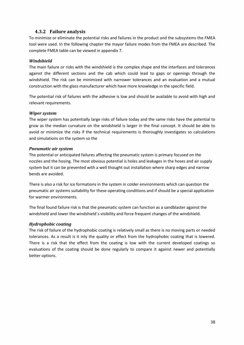
38
4.3.2 Failure analysis To minimize or eliminate the potential risks and failures in the product and the subsystems the FMEA
tool were used. In the following chapter the mayor failure modes from the FMEA are described. The
complete FMEA table can be viewed in appendix 7.
Windshield
The main failure or risks with the windshield is the complex shape and the interfaces and tolerances
against the different sections and the cab which could lead to gaps or openings through the
windshield. The risk can be minimized with narrower tolerances and an evaluation and a mutual
construction with the glass manufacturer which have more knowledge in the specific field.
The potential risk of failures with the adhesive is low and should be available to avoid with high and
relevant requirements.
Wiper system
The wiper system has potentially large risks of failure today and the same risks have the potential to
grow as the median curvature on the windshield is larger in the final concept. It should be able to
avoid or minimize the risks if the technical requirements is thoroughly investigates so calculations
and simulations on the system so the
Pneumatic air system
The potential or anticipated failures affecting the pneumatic system is primary focused on the
nozzles and the hosing. The most obvious potential is holes and leakages in the hoses and air supply
system but it can be prevented with a well thought out installation where sharp edges and narrow
bends are avoided.
There is also a risk for ice formations in the system in colder environments which can question the
pneumatic air systems suitability for these operating conditions and if should be a special application
for warmer environments.
The final found failure risk is that the pneumatic system can function as a sandblaster against the
windshield and lower the windshield´s visibility and force frequent changes of the windshield.
Hydrophobic coating
The risk of failure of the hydrophobic coating is relatively small as there is no moving parts or needed
tolerances. As a result is it inly the quality or effect from the hydrophobic coating that is lowered.
There is a risk that the effect from the coating is low with the current developed coatings so
evaluations of the coating should be done regularly to compare it against newer and potentially
better options.
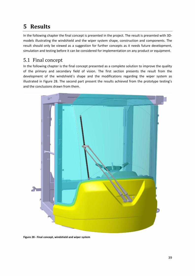
39
5 Results
In the following chapter the final concept is presented in the project. The result is presented with 3D-
models illustrating the windshield and the wiper system shape, construction and components. The
result should only be viewed as a suggestion for further concepts as it needs future development,
simulation and testing before it can be considered for implementation on any product or equipment.
5.1 Final concept In the following chapter is the final concept presented as a complete solution to improve the quality
of the primary and secondary field of vision. The first section presents the result from the
development of the windshield´s shape and the modifications regarding the wiper system as
illustrated in Figure 28. The second part present the results achieved from the prototype testing’s
and the conclusions drawn from them.
Figure 28 - Final concept, windshield and wiper system
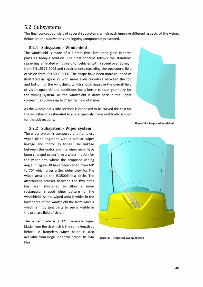
40
5.2 Subsystems The final concept consists of several subsystems which each improve different aspects of the vision.
Below are the subsystems and ingoing components presented.
5.2.1 Subsystem – Windshield The windshield is made of a 6,8mm thick laminated glass in three
parts as today’s solution. The final concept follows the standards
regarding laminated windshield for vehicles with a speed over 30km/h
from EN 15573:2008 and requirements regarding the operator’s field
of vision from ISO 5006:2006. The shape have been more rounded as
illustrated in Figure 29 with more even curvature between the top
and bottom of the windshield which should improve the overall field
of vision upwards and conditions for a better contact geometry for
the wiping system. As the windshield is draw back in the upper
corners it also gives up to 2° higher field of vision
As the windshield´s side sections is proposed to be curved the cost for
the windshield is estimated to rise as specialy made molds also is used
for the sidesections.
5.2.2 Subsystem – Wiper system The wiper system is composed of a frameless
wiper blade together with a similar wiper
linkage and motor as today. The linkage
between the motor and the wiper arms have
been changed to perform a wider motion for
the wiper arm where the proposed wiping
angle in Figure 30 have been raised from 60°
to 70° which gives a 2m wider view for the
wiped area on the ISO5006 test circle. The
attachment bracket between the two arms
has been shortened to allow a more
rectangular shaped wiper pattern for the
windshield. As the wiped area is wider in the
lower area of the windshield the front wheels
which is important parts to see is visible in
the primary field of vision.
The wiper blade is a 32” frameless wiper
blade from Bosch which is the same length as
before. A frameless wiper blade is also
available from Doga under the brand OPTIMA
Flex.
Figure 29 - Proposed windshield shape
Figure 30 - Proposed sweep pattern
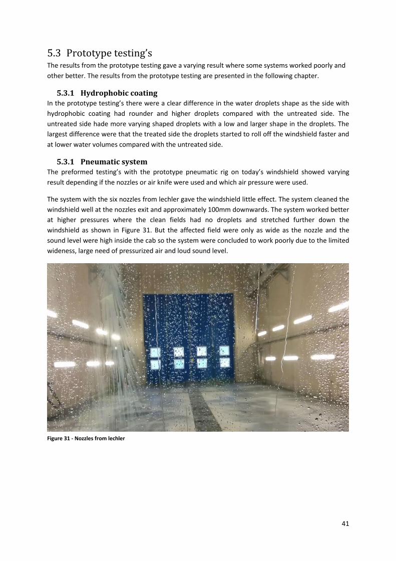
41
5.3 Prototype testing’s The results from the prototype testing gave a varying result where some systems worked poorly and
other better. The results from the prototype testing are presented in the following chapter.
5.3.1 Hydrophobic coating In the prototype testing’s there were a clear difference in the water droplets shape as the side with
hydrophobic coating had rounder and higher droplets compared with the untreated side. The
untreated side hade more varying shaped droplets with a low and larger shape in the droplets. The
largest difference were that the treated side the droplets started to roll off the windshield faster and
at lower water volumes compared with the untreated side.
5.3.1 Pneumatic system The preformed testing’s with the prototype pneumatic rig on today’s windshield showed varying
result depending if the nozzles or air knife were used and which air pressure were used.
The system with the six nozzles from lechler gave the windshield little effect. The system cleaned the
windshield well at the nozzles exit and approximately 100mm downwards. The system worked better
at higher pressures where the clean fields had no droplets and stretched further down the
windshield as shown in Figure 31. But the affected field were only as wide as the nozzle and the
sound level were high inside the cab so the system were concluded to work poorly due to the limited
wideness, large need of pressurized air and loud sound level.
Figure 31 - Nozzles from lechler
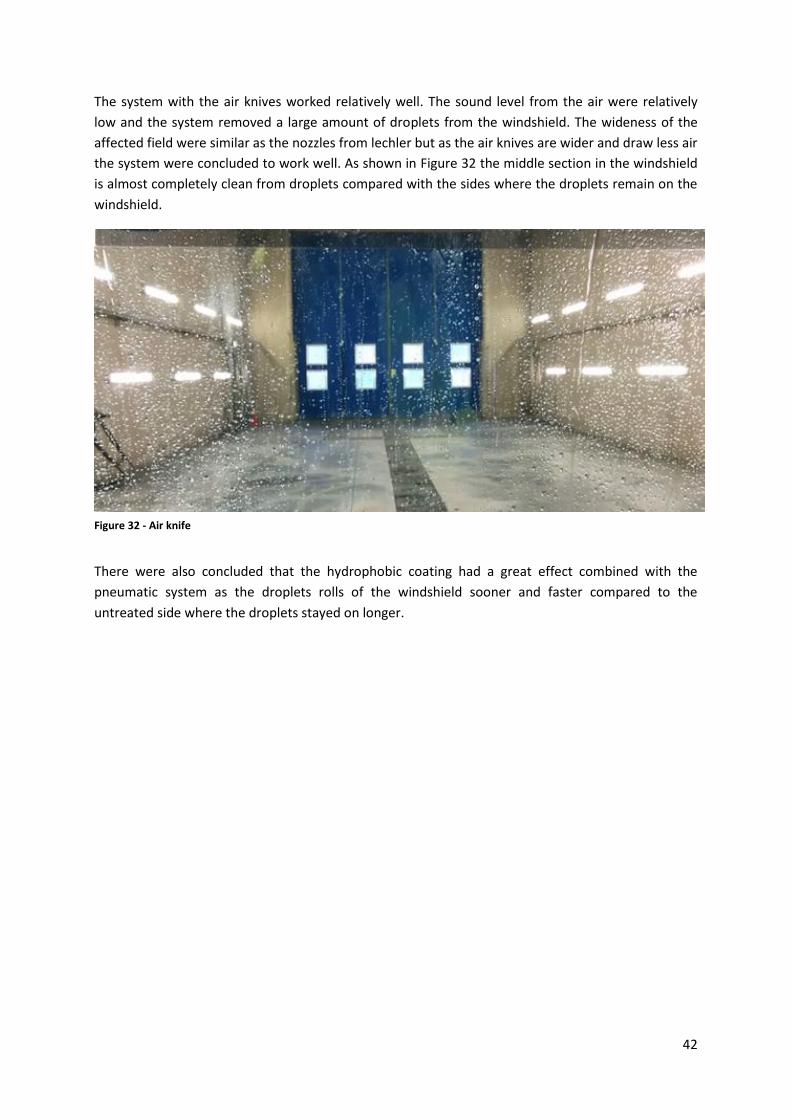
42
The system with the air knives worked relatively well. The sound level from the air were relatively
low and the system removed a large amount of droplets from the windshield. The wideness of the
affected field were similar as the nozzles from lechler but as the air knives are wider and draw less air
the system were concluded to work well. As shown in Figure 32 the middle section in the windshield
is almost completely clean from droplets compared with the sides where the droplets remain on the
windshield.
There were also concluded that the hydrophobic coating had a great effect combined with the
pneumatic system as the droplets rolls of the windshield sooner and faster compared to the
untreated side where the droplets stayed on longer.
Figure 32 - Air knife
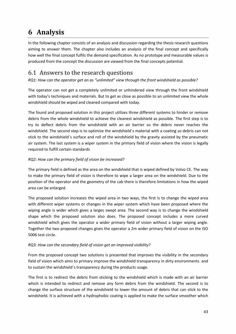
43
6 Analysis
In the following chapter consists of an analysis and discussion regarding the thesis research questions
aiming to answer them. The chapter also includes an analysis of the final concept and specifically
how well the final concept fulfils the demand specification. As no prototype and measurable values is
produced from the concept the discussion are viewed from the final concepts potential.
6.1 Answers to the research questions RQ1: How can the operator get an as “unlimited” view through the front windshield as possible?
The operator can not get a completely unlimited or unhindered view through the front windshield
with today’s techniques and materials. But to get as close as possible to an unlimited view the whole
windshield should be wiped and cleaned compared with today.
The found and proposed solution in this project utilizes three different systems to hinder or remove
debris from the whole windshield to achieve the cleanest windshield as possible. The first step is to
try to deflect debris from the windshield with an air barrier so the debris never reaches the
windshield. The second step is to optimize the windshield´s material with a coating so debris can not
stick to the windshield´s surface and roll of the windshield by the gravity assisted by the pneumatic
air system. The last system is a wiper system in the primary field of vision where the vision is legally
required to fulfill certain standards
RQ2: How can the primary field of vision be increased?
The primary field is defined as the area on the windshield that is wiped defined by Volvo CE. The way
to make the primary field of vision is therefore to wipe a larger area on the windshield. Due to the
position of the operator and the geometry of the cab there is therefore limitations in how the wiped
area can be enlarged.
The proposed solution increases the wiped area in two ways, the first is to change the wiped area
with different wiper systems or changes in the wiper system which have been proposed where the
wiping angle is wider which gives a larges swept area. The second way is to change the windshield
shape which the proposed solution also does. The proposed concept includes a more curved
windshield which gives the operator a wider primary field of vision without a larger wiping angle.
Together the two proposed changes gives the operator a 2m wider primary field of vision on the ISO
5006 test circle.
RQ3: How can the secondary field of vision get an improved visibility?
From the proposed concept two solutions is presented that improves the visibility in the secondary
field of vision which aims to primary improve the windshield transparency in dirty environments and
to sustain the windshield´s transparency during the products usage.
The first is to redirect the debris from sticking to the windshield which is made with an air barrier
which is intended to redirect and remove any form debris from the windshield. The second is to
change the surface structure of the windshield to lower the amount of debris that can stick to the
windshield. It is achieved with a hydrophobic coating is applied to make the surface smoother which
44
raises the contact angle for liquids. The surface has also anti-icing, anti-fogging and anti-sticking
characteristics which should lower the amount of debris obstructing the field of vision.
6.2 Evaluation of demand specification In the following section an evaluation of the demand specification has been done to evaluate and
estimate how well the concept fulfills the demand specification.
Function demands
Separate environments and keep pressure Yes
The concept separates and keeps the pressure for the relevant area in the case study as the
windshield is fitted against the cabs structure with an adhesive which also joins the three
windshield´s sections which together tightly seals the cab against the outside environment.
? Allow transparency over 75% in primary field of vision Yes
The transparency is not measured when the windshield is cleaned so to fulfil the requirement the
wiper system is required to fully function and keep the windshield clean. The intended wiper system
or the pneumatic system is independently able to fulfil the transparency requirements but as no test
of the proposed windshield shape and cleaning systems is tested the demand can not be guaranteed
to be fulfilled even if it is estimated to do so.
Allow transparency over 70% in secondary field of vision (when clean)
Yes
The concepts windshield is intended to be manufactured with the same glass and by the same
supplier as todays windshield which is ensures a transparency over 70% in the secondary field.
Have a fitted mechanical wiper covering ≤ 8m in test circle according to ISO 5006
≤ 8m
The concept has fitted mechanical wipers that cover 14,6m in the test circle according to ISO 5006.
Have fitted washers Yes
No development of washers has been conducted but the concept is intended to be fitted with the
same washer system as today’s solution.
? Remove water, snow and ice in primary field of vision Yes
Testing is required to confirm the demand but as there is a fitted wiper system on the concept it is
estimated to remove water, snow and ice. With new frameless wiper blades the systems cleaning
capabilities should be as good or better compared with today´s solution in the primary field of vision.
The pneumatic system should also help to remove all form of debris from sticking to the windshield.
? Remove debris(mineral, organic or biological) in primary field of vision
Yes
Testing is required to confirm that the concepts fitted wiper system clean debris. But it is estimated
to remove debris as good or better compared with today’s system. For dry debris the wipers should
not be needed as the pneumatic air system will prevent and remove debris from sticking to the
windshield.
? Remove water, snow and ice in secondary field of vision Yes
45
More extensive testing’s and development of a solution suitable for implementation is required to
test and fulfill the demand. But the pneumatic system should be able to remove all form of debris
from sticking to the windshield.
? Remove debris(mineral, organic or biological) in secondary field of vision
Yes
More extensive testing’s and development of a solution suitable for implementation is required to
test and fulfill the demand. But the pneumatic system should be able to remove all form of debris
from sticking to the windshield.
Geometry demands
Field of vision is consistent with ISO 5006 Yes
The field of vision in ISO 5006 is measured in how large masking there exists in the test circle from
pillars and other objects blocking the view. As the Pillars have not changed the field of vision is still
fulfilled.
Field of vision shows important parts for maneuvering the machine
Yes
The field of vision shows the important parts for maneuvering the machine. Today’s solution does
also show the important parts but many of the parts are visible in the secondary field of vision which
visibility should clearly improve with the concept.
Improve upward field of vision Yes
The upward field of vision have been improved as the windshield´s upper edge is drawn backwards
which primarily gives the operator better upward visibility in the upper corners.
Interface against A-pillars should not change Yes
The interface against the A-pillar is not changed in the concept as it were seen as a limitation in the
concept generation and detailed development. Close to the project end the limitation were
confirmed highly relevant as the new cab may be built with the same structure as today.
General demands
? Withstand minimal temperature -40°C
The windshield and wiper system consists of components which fulfils the same demands as today’s
components which are classified to withstand -40°. The pneumatic should also fulfill the temperature
demands. For the applied hydrophobic coating in the prototype testing’s no information regarding
the coatings temperature limitation could be found.
? Withstand maximal temperature +85°C
The windshield and wiper system consists of components which fulfils the same demands as today’s
components which are classified to withstand +85°. The pneumatic should also fulfill the
temperature demands but as not all parts are decided the demand can not be guaranteed. For the
applied hydrophobic coating in the prototype testing’s and the proposed coating no information
regarding the coatings temperature limitation could be found.
46
7 Conclusions and recommendations
In the following chapter the conclusions drawn from the project and process is presented followed
by recommendations for further development for the project.
7.1 Conclusions The thesis work has been a great experience giving a deeper understanding for the methodology
regarding product development and useful insight regarding Volvo CE products and structure. The
conclusions are divided in three parts, one about the applied methodology and process, one about
conclusions drawn from the prototype testing´s and one about the conclusions drawn from the
project.
7.1.1 The process The developing process was well applied to the project and the development was done in an
objective and structured process based on facts and results which should result in a quality secured
development process. The improvements that could have been done to the development process
would have been a faster development in phase one and two to allow more time for prototype
testing’s and further development of the concept based on the testing’s.
7.1.2 The prototype testing’s A large amount of information were archived from the prototype testing’s regarding both the
hydrophobic coating and the pneumatic system.
The applied hydrophobic coating in the prototype is a product developed as an aftermarket product
and it has issues with its limited lifetime and lack of durability. The lack of durability makes together
with the relatively low affect from the coating makes it unsuitable for implementation today.
From the prototype testing´s there were concluded that the pneumatic system should consist of as
wide nozzles as possible at the air flow do not widen. The prototype also showed that there is not
the amount of air moved that is important, instead it is the speed or force which the air knife
possessed. In the testing’s the air knife affected further down the windshield compared with the
nozzles.
7.1.3 The project The volumes of available and relevant information in this topic were low and often applied for the
automotive industry.
The project has been a large and interesting challenge including empirical studies and product
development and the project shows that there is room for improvement on today’s cleaning solution
for the front windshield. Improvement’s that can include windshield´s shape and wiper system which
adjustment and optimizes the shape and curvature of the windshield. There is also room for
implementation of new solutions involving new materials where the research and development is
under rapid development today showing promising result for self-cleaning applications with super
hydrophobic properties among others.
47
The project resulted in one concept based on a broad problem analysis where the problem,
limitations and other aspects were thoroughly investigated before the development process were
initiated.
7.2 Recommendations The project has touched several solutions which can be applied to improve the current product and
future generations. The recommendations for further investigation and development in the relevant
area and for the concept are presented below.
7.2.1 Construction It should be investigated if the windshield can be drawn back more to allow for better upward
visibility. As a result it should also be investigated if the roof beams can be draw back for a better
upward visibility in the upper corners as they block the visibility today and in the proposed concept.
If the proposed changes are tested it also needs investigation how FOPS and ROPS test are affected
by the changes. There is also the effect that more of the operator is less covered by the structural
metal roof and especially short people that sits closer to the windshield and how their security is
affected.
There is also recommendations to investigate and evaluate the 2D series wiper system for
pantographic sweep patterns from AM Equipment. Their system builds on sector gears to deliver
power to both pivot shafts compared with today’s solutions which consists of several linkages and
evaluate if the glitches resulting in the growing sweep angle could be lowered.
The pneumatic system should also be further investigated and customized nozzles or air knives
should be developed that follows the windshield curvature and have the right angle against the
windshield. In the prototype testing’s the pneumatic air system were tested with a continuously air
flow to create a barrier which requires a large amount of compressed air. The possibility of a system
where the air is launched in short air burst to “clean” the windshield should be tested and evaluated
as the required air supply would drastically decrease.
Currently there is no viable original equipment solution available on the market. But car
manufacturers as Volvo, Ford, Porsche and Kia among others applies Aqua Control on all their new
produced cars which according to the manufacturer should be effective up to 60.000km or up to 3
years (Saint-Gobain Autover, 2013). The durability is a large issue for all manufacturers but it is
recommended to follow the development of hydrophobic coatings and materials with hydrophobic
characteristics as it is currently under large developments and may be a better solution compared
with wipers in the future.
The proposed solution includes a large variation of possible solution which all can improve the field
of vision which all can be used together or by them self for special application for specific operating
environments. As an example is the pneumatic air system is suitable by itself for dry and dusty
environments where the wipers primary is used without washer fluid to remove dry debris from the
field of vision.
The possible failures listed and described in the FMEA should be taken under consideration for
further development together with the recommended.
48
7.2.2 Simulations Different simulations regarding the wiper system is needed to evaluate and investigate the forces
affecting the wiper system for an accurate dimension the wiper system. As a result it is
recommended to simulate all the affecting forces on the wiper as it operates and moves over the
windshield.
There can also be more simulations on the effect from the pneumatic system and simulations
investigating different loading pressures and air flow through the system. The aiming of the nozzles
are also recommended to further investigate through simulations for an effective system that covers
as much of the windshield as possible.
7.2.3 Prototype It is recommended to build a new and more complete prototype with the new shape for the
windshield were more thoroughly testing’s can be performed to evaluate the windshield´s shape and
effect on the wiper system, field of vision and the pneumatic system.
It would also be recommended to build out the prototype on the side sections of the windshield to
test the pneumatic system on the side sections where they could be most useful as there are no
wipers to remove debris and other forms of dirt blocking the field of vision.
There is also recommended to investigate and evaluate different types of linkage and especially on
the proposed windshield.
49
8 Bibliography
Barthlott, W. & Neinhuis, C., 1997. Purity of the sacred lotus,. Planta, 202(1), pp. 1-8.
Bell, J., 2006. Indroduktion till forskningsmetodik. Lund: Studentlitteratur.
Bengtsson, B., 1995. Tunga fordon grundkurs: Faktabok med forskningsuppgifter. Malmö: Gleerups.
Cassie & Baxter, 1944. Wettability of porous surfaces. Transactions of the Faraday Society, Volume
40, pp. 546-551.
Chang, Y. C. et al., 2007. Design and fabrication of a nanostructured surface combining antireflective
and enhanced-hydrophobic effects. Nanotechnology, 18(28).
Dassault Systems, 2015. [Online]
Available at: http://www.3ds.com/products-services/catia/products/v5/
[Accessed 22 10 2015].
Dron, W. & Tobin, D., 2013. Car maker McLaren waves goodbye to wipers. s.l.:The Sunday Times.
Drury, C. & Clement, M., 1978. The effect of area, density, and number of background characters on
visual search. Human factors, October, 20(5), pp. 597-602.
Eronen, M., 2011. Safety Glass Experts International: How to bend perfect shapes. Glass-Technology
international, 01 09, Volume 5, pp. 104-107.
European Committee for Standardization, 2008. Earth-moving machinery - Design requirements for
circulation on (EN 15573:2008). Brussels: Retrieved September 24, 2015, from InterRegs..
European Committee for Standardization, 2013. Earth-moving machinery - Safety - Part 1: General
requirements (EN 474-1:2006+A4:2013). Brussels: Retrieved September 24, 2015, from InterRegs..
Federal Aviation Administration, 2012. Aviation Maintenance Technician Handbook - Ariframe.
Oklahoma City: U.S. Department of Transportation.
Gonzalez, E. H., 1998. United States of America, Patent No. US 5852846 A.
Griggs, J., 2012. Omniphobia: the stuffs that stick at nothing. New Scientist, Volume 216(2892), pp.
46-49.
How Products Are Made, 2002. Windshield Wiper. [Online]
Available at: http://www.encyclopedia.com/doc/1G2-2897100108.html
[Accessed 28 September 2015].
Ide, T., 1973. Device for an automobile for securing visibility in the rain. Washington, United States of
America, Patent No. US 3769898 A.
InterRegs, 2015. International Regulations, ou. [Online]
Available at: http://www.interregs.com/services/
[Accessed 03 09 2015].
50
Johannesson, H., Persson, J.-G. & Pettersson, D., 2013. Produktutveckling: effektiva metoder för
konstruktion och design. 2nd ed. Stockholm: Liber.
Kako, T. et al., 2004. Adhesion and sliding of wet snow on a super-hydrophobic surface with
hydrophilic channels. Journal of Materials Science, 39(2), pp. 547-555.
Kumar, R., 2005. Research Methodology, A Step-by-Step Guide for Beginners. Singapore: Person
Education.
Motoda, K., 1988. Ultrasonic wiper. United States of America, Patent No. US 4768256 A.
Pilkington, 2015a. Education; Glass Processing. [Online]
Available at: https://www.pilkington.com/pilkington-
information/about+pilkington/education/processing/automotive+shaping+and+strengthening.htm
[Accessed 15 September 2015].
Pilkington, 2015b. Complex shaping; Automotive Glazing. [Online]
Available at: http://www.pilkington.com/en/automotive-international/automotive-glazing/complex-
shaping
[Accessed 15 September 2015].
Quéré, D., 2005. Non-sticking drops. Reports on Progress in Physics, 68(11), p. 2495.
Rahmawan, Y., Xu, L. & Yang, S., 2013. Self-assembly of nanostructures towards transparent,
superhydrophobic surfaces. Journal of Materials Chemistry A, Volume 1, pp. 2955-2969.
SAE International, 2015. About us. [Online]
Available at: http://www.sae.org/about/
[Accessed 04 09 2015].
Saint-Gobain Autover, 2013. Aquacontrol. [Online]
Available at: http://saint-gobain-autover.com/aquacontrol-water-repellent-coating
[Accessed 07 12 2015].
Sayer, J. R. et al., 1997. The influence of hydrophobic windshield coating on driver visual performance,
Ann Arbour, MI: University of Michigan Transportation Research Institute.
The International Organization for Standardization, 2006. Earth-moving machinery — Operator's field
of view - Test method and preformance criteria. s.l.:s.n.
TRICO, 2015. Wipers 101. [Online]
Available at: http://www.tricoproducts.com/Drivers/UnderstandingWipers/Wipers101
[Accessed 09 08 2015].
Ullman, D. G., 2010. The mechanical design proces. New York: McGraw-Hill.
Ulrich, K. T. & Eppinger, S. D., 2008. Product Design and Development. New York: McGraw-Hill.
Waken, 2015. Waken Wiper Systems. [Online]
Available at: http://www.nordiccontrol.com/dokument/torkarsystem/nccataloguewaken2012-08-

51
22.pdf
[Accessed 10 11 2015].
Wexco industries, 2015. heavy duty wipers & components. [Online]
Available at: http://ecommerce.cadel.ca/img/media/wexco_2012.pdf
[Accessed 10 11 2015].
Volvo CE, 2007. GDP BOOKLET, A guide to the global development process. Sweden: Volvo.
Volvo CE, 2015. Requirement Specification, Wiper system. Eskilstuna: s.n.
Österlin, K., 2010. Design i fokus för produktutveckling - Varför ser saker ut som de gör?. Sweden:
Liber.

52
9 Appendixes
Appendix 1 - Gantt-schedule
Appendix 2 - Mapping of important visible parts
Appendix 3 - Benchmarking
Appendix 4 - Nozzle, Lechler
Appendix 5 - Air knife, Exair
Appendix 6 - FMEA
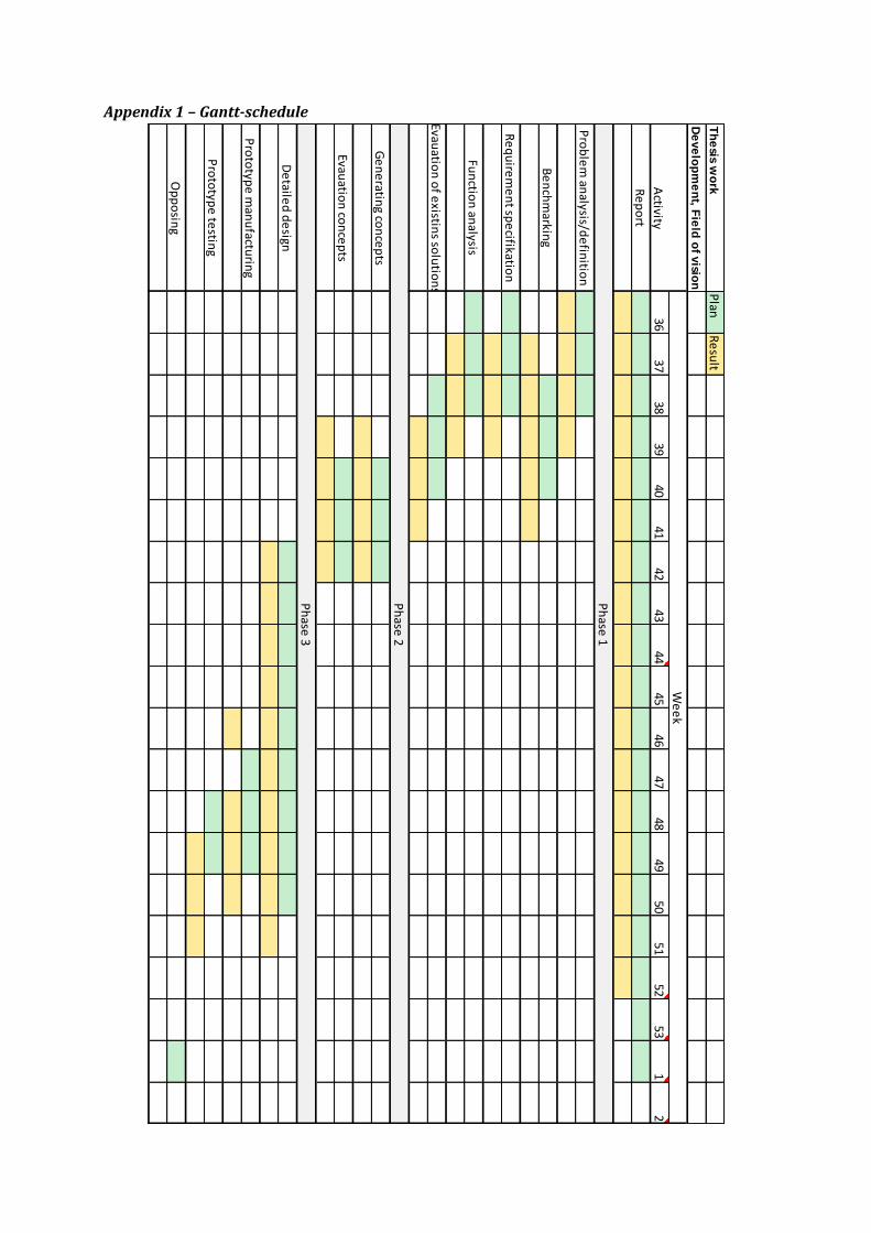
Appendix 1 – Gantt-schedule
Plan
Re
sult
3637
3839
4041
4243
4445
4647
4849
5051
5253
12
De
ve
lop
me
nt, F
ield
of v
ision
Th
esis w
ork
Pro
ble
m an
alysis/de
finitio
n
Pro
totyp
e m
anu
facturin
g
Ge
ne
rating co
nce
pts
Evauatio
n co
nce
pts
Pro
totyp
e te
sting
Op
po
sing
We
ek
Activity
Ph
ase 1
Re
po
rt
Be
nch
markin
g
Re
qu
irem
en
t spe
cifikation
De
tailed
de
sign
Fun
ction
analysis
Evauatio
n o
f existin
s solu
tion
s
Ph
ase 2
Ph
ase 3
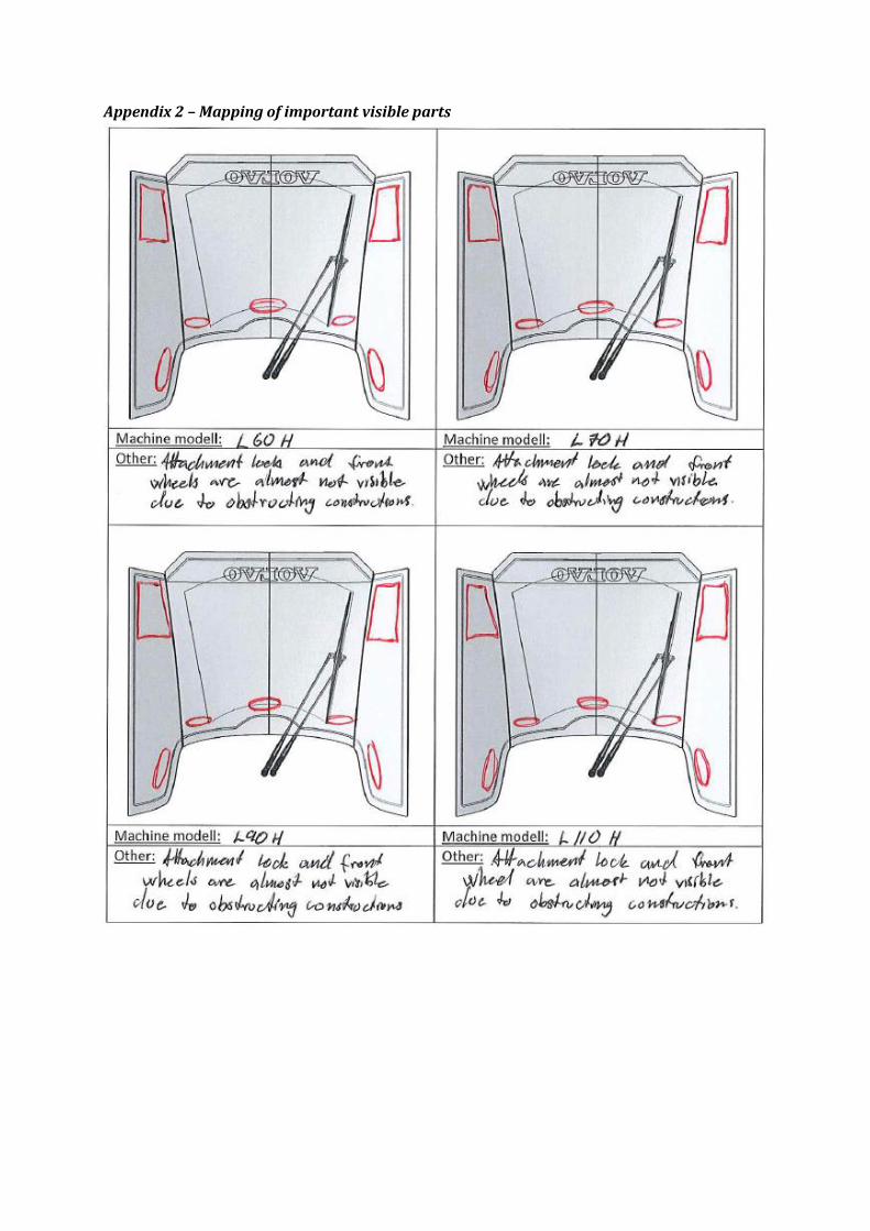
Appendix 2 – Mapping of important visible parts
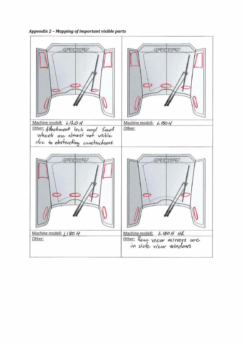
Appendix 2 – Mapping of important visible parts
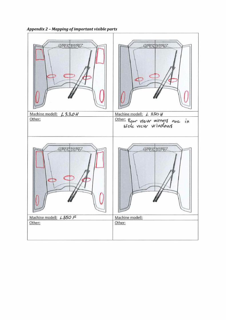
Appendix 2 – Mapping of important visible parts
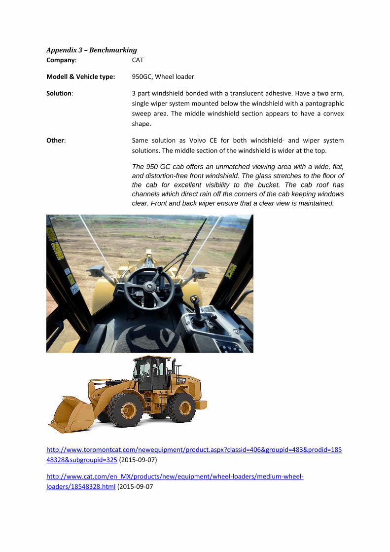
Appendix 3 – Benchmarking
Company: CAT
Modell & Vehicle type: 950GC, Wheel loader
Solution: 3 part windshield bonded with a translucent adhesive. Have a two arm,
single wiper system mounted below the windshield with a pantographic
sweep area. The middle windshield section appears to have a convex
shape.
Other: Same solution as Volvo CE for both windshield- and wiper system
solutions. The middle section of the windshield is wider at the top.
The 950 GC cab offers an unmatched viewing area with a wide, flat,
and distortion-free front windshield. The glass stretches to the floor of
the cab for excellent visibility to the bucket. The cab roof has
channels which direct rain off the corners of the cab keeping windows
clear. Front and back wiper ensure that a clear view is maintained.
http://www.toromontcat.com/newequipment/product.aspx?classid=406&groupid=483&prodid=185
48328&subgroupid=325 (2015-09-07)
http://www.cat.com/en_MX/products/new/equipment/wheel-loaders/medium-wheel-
loaders/18548328.html (2015-09-07

Appendix 2 – Benchmarking
Company: Komatsu
Modell & Vehicle type: WA380-8, Wheel loader
Solution: 3 part windshield bonded with a translucent adhesive. Have a two arm,
single wiper system mounted below the windshield with a pantographic
sweep area. The middle section of the windshield appears to have a
swept shape.
Other: Same solution as Volvo CE for both windshield- and wiper system
solutions. The middle section of the windshield is wider at the top.
A wide pillar-less flat glass provides excellent front visibility. The wiper
arm covers a large area to provide great visibility even on rainy days.
http://www.komatsuamerica.com/equipment/wheelloaders/176-600hp/wa380-8 (2015-09-07)
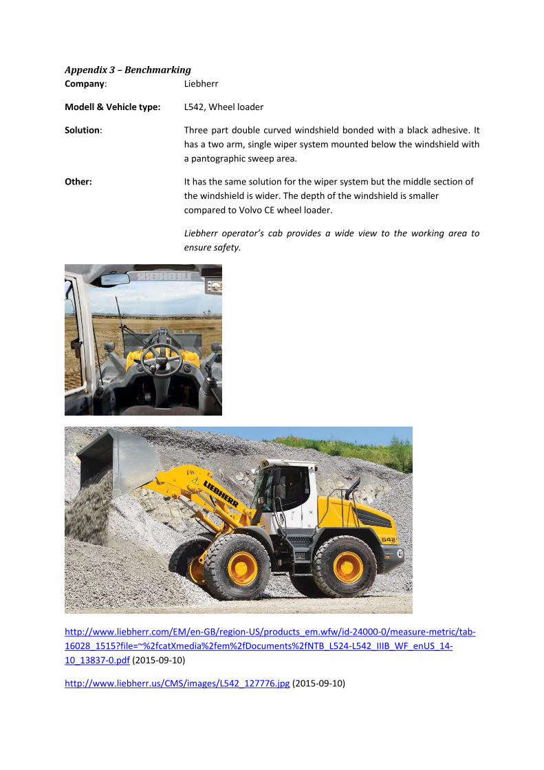
Appendix 3 – Benchmarking
Company: Liebherr
Modell & Vehicle type: L542, Wheel loader
Solution: Three part double curved windshield bonded with a black adhesive. It
has a two arm, single wiper system mounted below the windshield with
a pantographic sweep area.
Other: It has the same solution for the wiper system but the middle section of
the windshield is wider. The depth of the windshield is smaller
compared to Volvo CE wheel loader.
Liebherr operator’s cab provides a wide view to the working area to
ensure safety.
http://www.liebherr.com/EM/en-GB/region-US/products_em.wfw/id-24000-0/measure-metric/tab-
16028_1515?file=~%2fcatXmedia%2fem%2fDocuments%2fNTB_L524-L542_IIIB_WF_enUS_14-
10_13837-0.pdf (2015-09-10)
http://www.liebherr.us/CMS/images/L542_127776.jpg (2015-09-10)
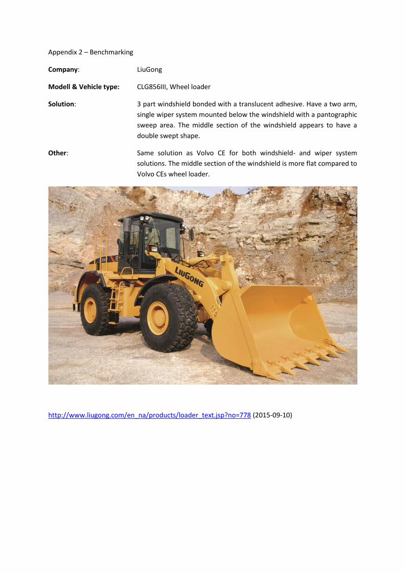
Appendix 2 – Benchmarking
Company: LiuGong
Modell & Vehicle type: CLG856III, Wheel loader
Solution: 3 part windshield bonded with a translucent adhesive. Have a two arm,
single wiper system mounted below the windshield with a pantographic
sweep area. The middle section of the windshield appears to have a
double swept shape.
Other: Same solution as Volvo CE for both windshield- and wiper system
solutions. The middle section of the windshield is more flat compared to
Volvo CEs wheel loader.
http://www.liugong.com/en_na/products/loader_text.jsp?no=778 (2015-09-10)
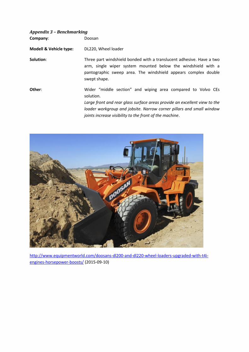
Appendix 3 – Benchmarking
Company: Doosan
Modell & Vehicle type: DL220, Wheel loader
Solution: Three part windshield bonded with a translucent adhesive. Have a two
arm, single wiper system mounted below the windshield with a
pantographic sweep area. The windshield appears complex double
swept shape.
Other: Wider “middle section” and wiping area compared to Volvo CEs
solution.
Large front and rear glass surface areas provide an excellent view to the
loader workgroup and jobsite. Narrow corner pillars and small window
joints increase visibility to the front of the machine.
http://www.equipmentworld.com/doosans-dl200-and-dl220-wheel-loaders-upgraded-with-t4i-
engines-horsepower-boosts/ (2015-09-10)
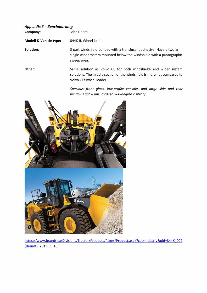
Appendix 3 – Benchmarking
Company: John Deere
Modell & Vehicle type: 844K-II, Wheel loader
Solution: 3 part windshield bonded with a translucent adhesive. Have a two arm,
single wiper system mounted below the windshield with a pantographic
sweep area.
Other: Same solution as Volvo CE for both windshield- and wiper system
solutions. The middle section of the windshield is more flat compared to
Volvo CEs wheel loader.
Spacious front glass, low-profile console, and large side and rear
windows allow unsurpassed 360-degree visibility.
https://www.brandt.ca/Divisions/Tractor/Products/Pages/Product.aspx?cat=Industry&pid=844K_002
(Brandt) (2015-09-10)
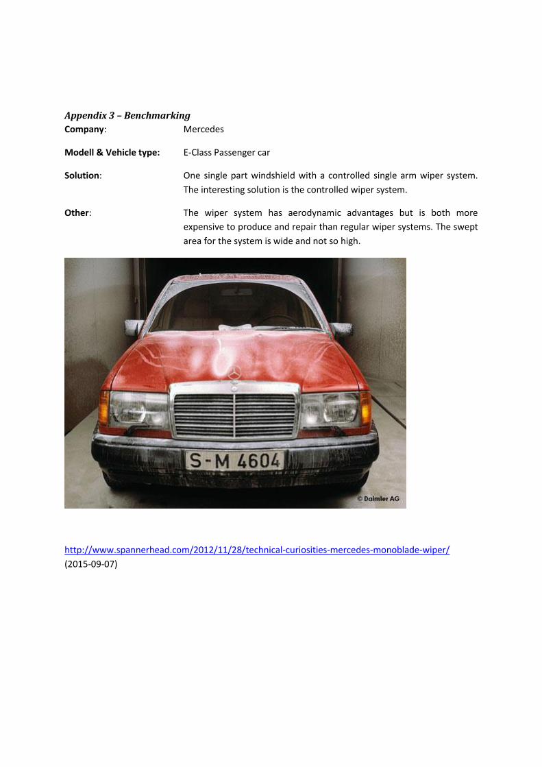
Appendix 3 – Benchmarking
Company: Mercedes
Modell & Vehicle type: E-Class Passenger car
Solution: One single part windshield with a controlled single arm wiper system.
The interesting solution is the controlled wiper system.
Other: The wiper system has aerodynamic advantages but is both more
expensive to produce and repair than regular wiper systems. The swept
area for the system is wide and not so high.
http://www.spannerhead.com/2012/11/28/technical-curiosities-mercedes-monoblade-wiper/
(2015-09-07)
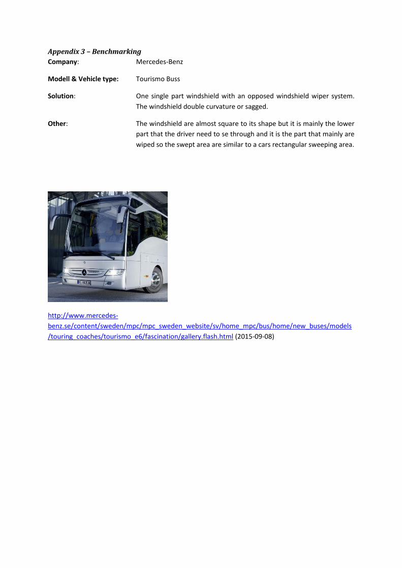
Appendix 3 – Benchmarking
Company: Mercedes-Benz
Modell & Vehicle type: Tourismo Buss
Solution: One single part windshield with an opposed windshield wiper system.
The windshield double curvature or sagged.
Other: The windshield are almost square to its shape but it is mainly the lower
part that the driver need to se through and it is the part that mainly are
wiped so the swept area are similar to a cars rectangular sweeping area.
http://www.mercedes-
benz.se/content/sweden/mpc/mpc_sweden_website/sv/home_mpc/bus/home/new_buses/models
/touring_coaches/tourismo_e6/fascination/gallery.flash.html (2015-09-08)
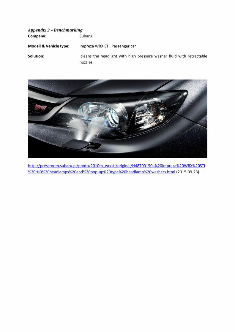
Appendix 3 – Benchmarking
Company: Subaru
Modell & Vehicle type: Impreza WRX STI, Passenger car
Solution: cleans the headlight with high pressure washer fluid with retractable
nozzles.
http://pressroom.subaru.pl/photo/2010m_wrxsti/original/H48700150a%20Impreza%20WRX%20STI
%20HID%20headlamps%20and%20pop-up%20type%20headlamp%20washers.html (2015-09-23)
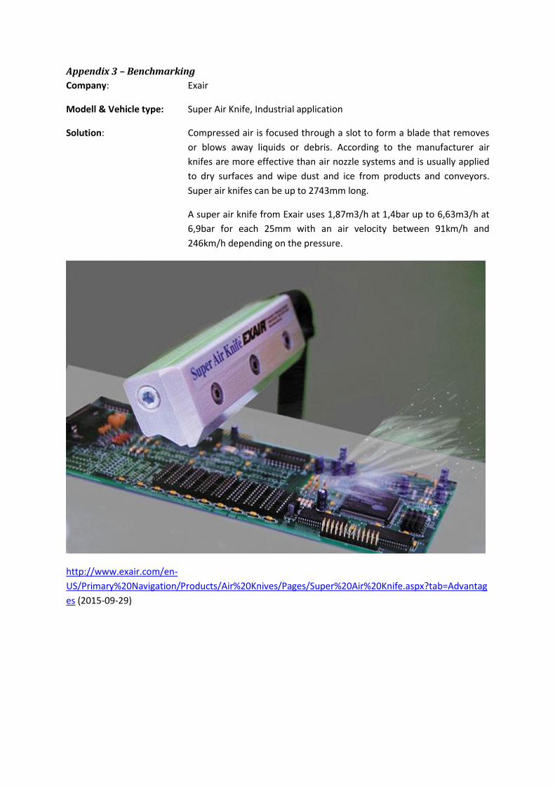
Appendix 3 – Benchmarking
Company: Exair
Modell & Vehicle type: Super Air Knife, Industrial application
Solution: Compressed air is focused through a slot to form a blade that removes
or blows away liquids or debris. According to the manufacturer air
knifes are more effective than air nozzle systems and is usually applied
to dry surfaces and wipe dust and ice from products and conveyors.
Super air knifes can be up to 2743mm long.
A super air knife from Exair uses 1,87m3/h at 1,4bar up to 6,63m3/h at
6,9bar for each 25mm with an air velocity between 91km/h and
246km/h depending on the pressure.
http://www.exair.com/en-
US/Primary%20Navigation/Products/Air%20Knives/Pages/Super%20Air%20Knife.aspx?tab=Advantag
es (2015-09-29)
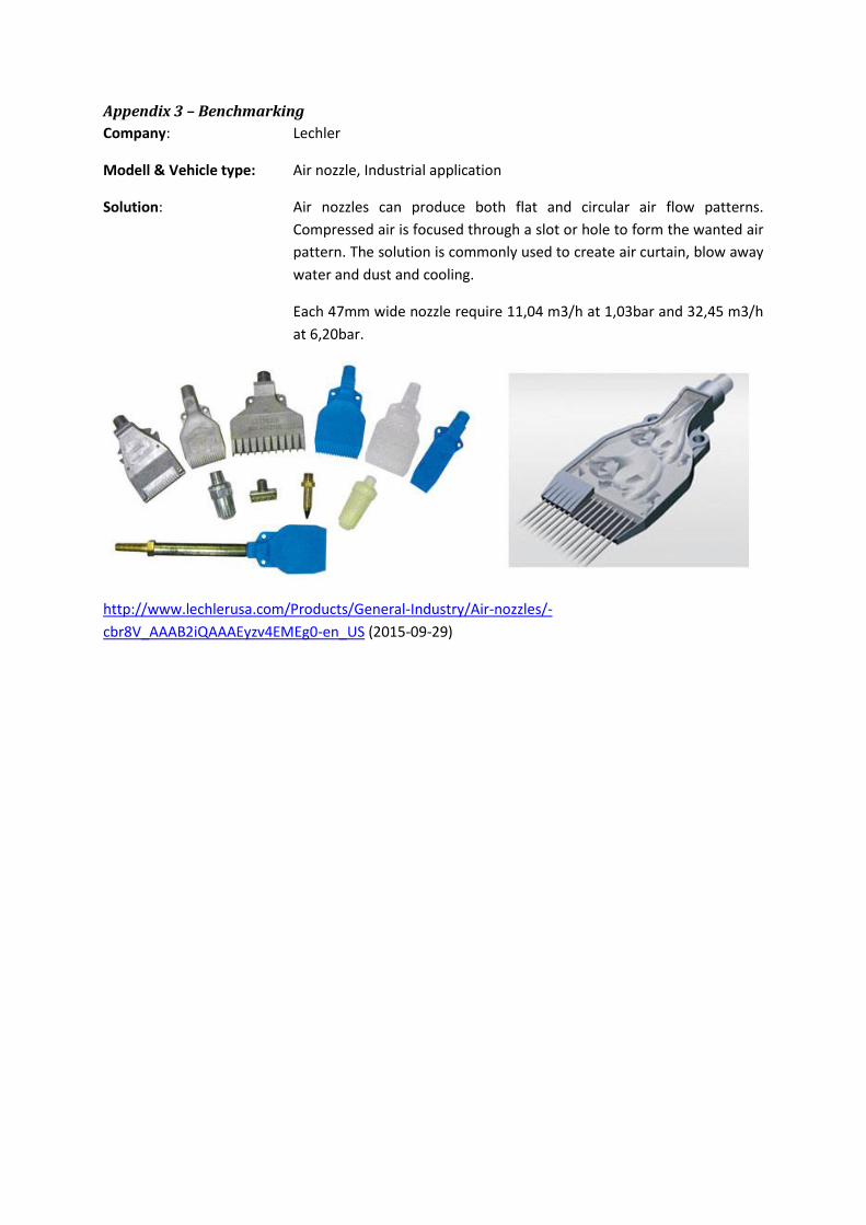
Appendix 3 – Benchmarking
Company: Lechler
Modell & Vehicle type: Air nozzle, Industrial application
Solution: Air nozzles can produce both flat and circular air flow patterns.
Compressed air is focused through a slot or hole to form the wanted air
pattern. The solution is commonly used to create air curtain, blow away
water and dust and cooling.
Each 47mm wide nozzle require 11,04 m3/h at 1,03bar and 32,45 m3/h
at 6,20bar.
http://www.lechlerusa.com/Products/General-Industry/Air-nozzles/-
cbr8V_AAAB2iQAAAEyzv4EMEg0-en_US (2015-09-29)
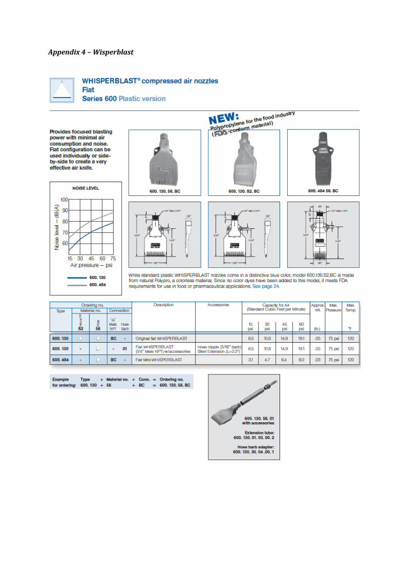
Appendix 4 – Wisperblast
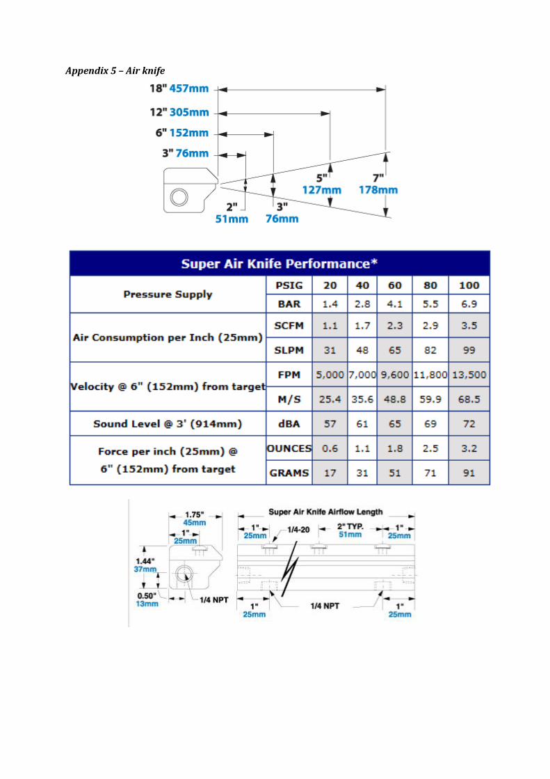
Appendix 5 – Air knife

Appendix 6 – FMEA
Article
and
fun
ction
Failure
mo
de
Failure
effe
ctR
eco
me
nd
ed
action
Win
dsh
ield
, sep
arate e
nviro
nm
en
tsW
ear o
n ad
he
sive jo
int
Leakage
be
twe
en
win
dsh
ield
sectio
nh
ighe
r req
uire
me
nts o
n th
e ad
he
sive
wro
ng sh
ape
on
glasso
pe
nin
g be
twe
en
sectio
ns
narro
w to
leran
ces
Inte
rface p
rob
lem
sn
arrow
tole
rance
s
Wip
er syste
m, cle
an p
rimary fie
ld o
f vision
Co
rrosio
n, M
oto
rLo
we
r effice
ncy, sp
ee
dEvalu
ation
of m
oto
r, mo
tor iso
lation
Bre
akdo
wn
, mo
tor
No
wip
ing
Stron
ger m
oto
r
Dam
ages o
the
r parts
Stron
ger m
oto
r com
po
ne
nts
Co
rrosio
n, Lin
kageLo
we
r transm
itted
po
we
rStro
nge
r linkage
agains co
rrosio
n
Larger w
ipin
g angle
Stron
ger lin
kage lim
iting an
gle gro
wth
Narro
we
r no
min
al wio
ing an
gle
De
form
ation
, linkage
Re
du
ced
wip
ing e
ffectivn
ess
Stron
ger lin
kage
Larger w
ipin
g angle
Stron
ger lin
kage lim
iting an
gle gro
wth
Narro
we
r no
min
al wio
ing an
gle
Bre
akdo
wn
, linkage
No
wip
ing
Stron
ger lin
kage
Dam
ages th
e w
ind
shie
ldStro
nge
r linkage
Co
rrosio
n, W
ipe
r blad
eLo
we
r wip
ing q
uality
Re
place
wip
er b
lade
Bre
akdo
wn
, Wh
ipe
r blad
eLo
we
r qu
ality or n
o w
ipin
gEvalu
ate b
lade
man
ufactu
rer
Dam
ages th
e w
ind
shie
ldEvalu
ate b
lade
man
ufactu
rer
Pn
eu
matic syste
m, ke
ep
spe
cified
area cle
anH
oe
ls in h
ose
sLo
we
r pre
ssure
in n
ozzle
sEvalu
ation
of h
ose
/ho
se p
ath
Airflo
w in
side
cab stru
cture
Evaluatio
n o
f ho
se/h
ose
path
Co
rrosio
n, n
ozzle
Smale
r op
en
ings in
no
zzleEvalu
ation
of n
ozzle
mate
rial
Bre
akdo
wn
, no
zzleLo
se stru
cture
d airflo
wEvalu
ation
of n
ozzle
req
uire
me
nts
De
bris b
lockin
g no
zzles
Low
er airflo
wEvalu
ation
of n
ozzle
po
sition
Evaluatio
n o
f con
stant airflo
w
Ice fo
rmatio
n in
system
Low
or b
locke
d airflo
wEvalu
ation
of ap
plicatio
n e
niro
nm
en
t
Sand
is blo
wn
on
win
dsh
ield
Sand
blaste
r effe
ct cause
dam
aging
Evaluatio
n o
f angle
and
air pre
ssure
Hyd
rop
ho
bic co
ating, ke
ep
spe
cified
area cle
anLo
w d
urab
ilitylo
we
r hyd
rop
ho
bic e
ffect
Evaluate
cho
ise o
f man
ufactu
rer
Re
fill the
coatin
g