Embed Size (px)
Citation preview

IEEJ Journal of Industry ApplicationsVol.8 No.4 pp.615–622 DOI: 10.1541/ieejjia.8.615
Paper
Improvement of High-Frequency Characteristics of Small-Size ToroidalReactors with New Wire Guides
Hideki Ayano∗ Senior Member, Akira Fujimura∗ Non-member
Yoshihiro Matsui∗∗ Member
(Manuscript received July 2, 2018, revised April 9, 2019)
In this paper, a new reactor with a wire guide for a small-size toroidal core that can be used in the high frequencyrange is proposed. Theoretically, the reactor size can be reduced in proportion to the switching frequency. How-ever, practically, as the switching frequency is increased, reactors are affected by the parasitic capacitance existingbetween the windings and between the winding and the core, and the inductance characteristic of the reactors is deteri-orated. Therefore, there is a limit to increasing the switching frequency. This paper proposes two types of wire guides,namely a two-layer winding guide and a three-layer winding guide, to reduce the parasitic capacitance. Moreover, theimpedance characteristics of the reactors using the proposed wire guides are evaluated. The wire guides are manufac-tured using a 3D printer and attached to the center hole of the toroidal core. With the proposed guides, the parasiticcapacitance decreases by 0.73 times and 0.66 times compared with the conventional reactor. The linear regions of theimpedance, which can be regarded as a pure inductance, are enlarged. In addition, the materials of the wire guide arealso evaluated. It is shown that the ultraviolet curing resin guide is superior to the thermoplastic resin guide.
Keywords: reactor, parasitic capacitance, high frequency, wire guide
1. Introduction
Recently, power devices such as SiC and GaN have beenput into practical use, and low-loss and high-frequency drivehas been realized (1). Reactors used in DC-DC converterscan theoretically reduce current ripples in proportion to fre-quency. In other words, the higher the switching frequencyis, the smaller the inductance can be used if the current rippleis the same. Especially, since the size and weight of con-verter systems are dominated by those of reactors, the sizeand weight reductions of reactors can greatly contribute tothose reductions of converter systems. Furthermore, by in-creasing the switching frequency and reducing the currentripples, the vibrations of the reactors and the motor systemcan be reduced, so the acoustic noises can be reduced. In ad-dition, the response of the current control can be improved byshortening the control cycle of the converter. However, prac-tically, as the switching frequency is increased, the reactorsare affected by the parasitic capacitances existing between thewindings and between the winding and the core, and the in-ductance characteristic of the reactor is deteriorated (2). As aresult, there is a limit to increasing the switching frequency (3).This problem has been pointed out about not only reactorsbut also EMI filters and high frequency transformers, andtheir modeling, impedance evaluation and winding methodin the high frequency region have been reported (4)–(9). The au-thors had reported the wire guide for a relatively large-sizecore (10). The wire guide to reduce the parasitic capacitances
∗ National Institute of Technology, Tokyo College1220-2, Kunugida-machi, Hachioji, Tokyo 193-0997, Japan
∗∗ Fukuoka Institute of Technology3-30-1, Wajiro-higashi, Higashi-ku, Fukuoka 811-0295, Japan
for a relatively large-size core had been reported.This paper proposes new reactors to which the technique
shown in the Ref. (10) presented by the authors are applied,and they can be used under high frequency conditions withwire guides for a small-size toroidal core. The wire guidesare manufactured by using a 3D printer and are attached tothe center hole of the toroidal core. In the case of a small-size core, the winding arrangement and the realization of thewire guide are restricted. The wire guides enable to reducethe parasitic capacitances between the windings and betweenthe winding and the core. In this paper, the impedance char-acteristics of the reactors using the proposed wire guides areevaluated. Then, the reduction effect of the parasitic capaci-tances and the expanding effect of the frequency range whichcan be regarded as a pure inductance are evaluated. More-over, the impedance characteristics are evaluated when theshape and the material of the guide are changed.
2. Problem of a Reactor used Under High Fre-quency Conditions
Figure 1 shows a main circuit of a bidirectional DC-DC
Fig. 1. DC-DC converter system
c© 2019 The Institute of Electrical Engineers of Japan. 615
High-Frequency Reactors with New Wire Guides(Hideki Ayano et al.)
converter (E1 < E2). The system of Fig. 1 consists of twoswitching devices (S 1, S 2) and a reactor. The red line isthe current path of the boost converter, and the voltage E1
is boosted to E2 via the switching devices. The blue line isthe current path of the buck converter, and the voltage E2 isstepped down to E1 via the switching devices. This circuitis used in electric vehicles with rechargeable batteries and isoperated as the boost converter and the buck converter in thepower running and the regenerative modes, respectively.
Figure 2 shows the simulation results of the current i� flow-ing in the inductance L when the switching frequency ischanged in the power running mode. In i�s, the ripple cur-rents are superimposed on the DC current. If the ripple cur-rents are large, adverse effects such as vibration and noise ofthe reactor may occur. The magnitude of the ripple can becalculated by
Iripple =E1
L× Ts2, · · · · · · · · · · · · · · · · · · · · · · · · · · · · · · · (1)
where Ts2 is the conduction time of S 2. From (1), the ripplecurrent can be reduced by (i) increasing the inductance of Lor (ii) increasing the switching frequency (decreasing Ts2).The method (ii) is generally used since the weight and vol-ume of the reactor becomes large in method (i). Accordingto Fig. 2, under the ideal condition, the higher the switchingfrequency is, the smaller the ripple current becomes.
Figure 3 shows a conventional reactor with a toroidal-coreand its equivalent circuit under the high switching frequencycondition. Figure 3(a) is the schematic of a reactor in which
Fig. 2. Currents of the DC-DC converter when theswitching frequency is changed
(a) reactor model
(b) equivalent circuit
Fig. 3. A conventional reactor with a toroidal-core andits equivalent circuit
a copper wire coil is wound around a toroidal core. Sincethe toroidal core has no gap, the leakage flux is small. How-ever, when the coil windings are increased, the wires becomedensely gathered together at the center hole of the toroidalcore. In this case, the parasitic capacitances between the cop-per wires and between the copper wire and the core may af-fect the impedance characteristic of the reactor.
Figure 3(b) is the equivalent circuit of the reactor at highswitching frequency (5). It is assumed that the coil windings(t1, t2, t3) whose diameters are r are wound at the intervald and the distances between the coil windings and the coreare h. In this case, the parasitic capacitances Cd and Ch perunit length, which exists between the windings and betweenthe winding and the core, respectively, can be expressed asfollows (5):
Cd =πε0
ln
⎧⎪⎪⎪⎨⎪⎪⎪⎩ d2r+
√(d2r
)2
− 1
⎫⎪⎪⎪⎬⎪⎪⎪⎭, · · · · · · · · · · · · · · · · · · (2)
Ch =2πε0
ln
⎧⎪⎪⎪⎨⎪⎪⎪⎩hr+
√(hr
)2
− 1
⎫⎪⎪⎪⎬⎪⎪⎪⎭. · · · · · · · · · · · · · · · · · · · · · (3)
From (2) and (3), if d and h can be increased, Cd and Ch canbe reduced, and the impedance characteristic of the reactorcan be improved under the high switching frequency condi-tion.
3. The Proposal of New Wire Guide for aToroidal Core
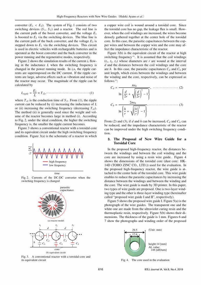
In the proposed high-frequency reactor, the distances be-tween the windings and between the coil winding and thecore are increased by using a resin wire guide. Figure 4shows the dimensions of the toroidal core (dust core: HK-14D (TOHO ZINC CO., LTD.)) used for the evaluation. Inthe proposed high-frequency reactor, the wire guide is at-tached to the center hole of the toroidal core. This wire guideenables to reduce the parasitic capacitances by increasing thedistance between the windings and between the winding andthe core. The wire guide is made by 3D printer. In this paper,two types of wire guide are proposed. One is two-layer wind-ing type and the other is three-layer winding type (hereinaftercalled “proposed wire guide I and II”, respectively).
Figure 5 shows the proposed wire guide I. Figure 5(a) is thephotograph of the wire guides. The transparent one and thewhite one are made from the ultraviolet curing resin and thethermoplastic resin, respectively. Figure 5(b) shows their di-mensions. The thickness of the guide is 1 mm. Figures 6 and7 show the photographs and winding order of the proposed
Fig. 4. The core used in the evaluation
616 IEEJ Journal IA, Vol.8, No.4, 2019

High-Frequency Reactors with New Wire Guides(Hideki Ayano et al.)
(a) photograph of wire guides
(b) dimensions of the wire guide
Fig. 5. Proposed wire guide I
Fig. 6. Photographs of the reactor with proposed wireguide I
Fig. 7. Winding order of the reactor with the proposedwire guide I
high-frequency reactor with proposed wire guide I, respec-tively. The winding orders of Fig. 7 show only a part of thewhole. The enameled copper wire with a diameter of 0.6 mmis used for the coil winding, and the number of turns is 56†.As shown in the enlarged view of Fig. 6, the length of theguide in the axial direction is slightly longer than that ofthe core. And, as shown in Fig. 7, the windings are alter-nately wound around the inner frame of the wire guide andthe clearance between the core and the wire guide. The wireguide keeps the distances between the wires and between thewires and the core as far as possible. In this case, althoughthere is concern about the increase of the leakage magneticflux, it may become small since the toroidal core has no gap.In the proposed reactor, the part of the wire guide protruding
† The rated current of the reactor is assumed to be several A. Because ofthe high frequency condition, thin wires connected in parallel or litz wiresmay be used in consideration of the skin effect. In this paper, each windingof the all prototypes is 56 turns by using single wire.
(a) photograph of wire guides
(b) dimensions of the wire guide
Fig. 8. Proposed wire guide II
Fig. 9. Photographs of reactor with the proposed wireguide II
Fig. 10. Winding order of the reactor with the proposedwire guide II
from the core in its axial direction prevents overlapping of thewindings and extends the distance between the windings andthe core. As a result, the proposed wire guide has the effectof reducing the parasitic capacitances Cd and Ch in Fig. 3.
Figure 8 shows the proposed wire guide II. Figure 8(a) isthe photograph of the wire guides and Fig. 8(b) shows theirdimensions. The thickness of the guide is 0.5 mm, so thatthe windings are not crowded at the inner frame of the wireguide. Because the guide is extremely thin, the guide mustbe made from the ultraviolet curing resin which can be man-ufactured with high accuracy. Figures 9 and 10 show the pho-tographs and winding order of the proposed high-frequencyreactor with the proposed wire guide II, respectively††. The†† The structure of Fig. 8 is designed so that the pillars between the sections
support the inner layer do not interfere with wiring. Although the numberof sections is different in the guides I and II, it is clear from the photographsof Figs. 6 and 9 that the windings are evenly wound regardless of the pillarsbetween the sections.
617 IEEJ Journal IA, Vol.8, No.4, 2019

High-Frequency Reactors with New Wire Guides(Hideki Ayano et al.)
winding orders of Fig. 10 show only a part of the whole. Theenameled copper wire with a diameter of 0.6 mm is used forthe coil winding and the number of turns is 56, which are thesame condition in Fig. 6. By winding in the order shown inFig. 10, the ratios of the number of windings at the outer part,the middle part, and the center part can be 3: 2: 1. The wireguide keeps the distances between the wires and between thewires and the core as far as possible, which is the same asFig. 7. The wire guide of Fig. 8 can use the inner space ofthe center hole of the toroidal core than that of Fig. 5. Thelength of the outer frame of the guide in the axial directionis slightly longer than that of the core, and that of the innerframe is slightly longer than that of the outer frame as shownin Fig. 8(b) and Fig. 9. The differences in the length preventoverlapping of the windings. As a result, the proposed wireguide has the effect of reducing the parasitic capacitances Cd
and Ch in Fig. 3.
4. Evaluations of the Impedance Characteristics
4.1 The Effect of the Proposed Wire Guides In thissection, the impedance characteristics of the proposed reac-tors shown in Figs. 6 and 9 are evaluated. In addition, theconventional reactor and the concentrated winding reactorin which the coil winding is densely wound around a partof the core are also evaluated for comparison. Figure 11shows the photographs of a conventional reactor and a con-centrated winding reactor, respectively. The toroidal core(HK-14D) shown in Fig. 4 is used for all reactors, and thecopper wire diameter and the turns of the coil winding arefixed to be 0.6 mm and 56, respectively. The material of theguides for the proposed wire guide I and II are the ultravioletcuring resin. For the measurement, the impedance analyzer(E4990A, KEYSIGHT Technology) is used.
Figure 12 shows the impedance characteristics of each re-actor. The resonance frequencies of the conventional reactor,the concentrated winding reactor, the reactors with the pro-posed wire guide I and II are 3.39 MHz, 1.60 MHz, 4.14 MHzand 4.14 MHz, respectively. Both resonance frequencies ofthe proposed reactors can be increased by 750 kHz than thatof the conventional reactor. The resonance frequency of theconcentrated winding reactor is 1.87 MHz lower than that ofthe conventional reactor, and the characteristics at high fre-quencies are remarkably deteriorated.
Table 1 shows the resonance frequencies fr, inductances Land parasitic capacitances C of each reactor. Each reactor canbe regarded as an LC parallel circuit. However, the influenceof resistance appears near each resonance point. Appendixshows detailed impedance evaluation. Here, L are derivedassuming that the reactor can be approximated to be only theinductance L at 100 kHz†††. C is obtained by substituting frand L into
C =1
(2π fr)2L. · · · · · · · · · · · · · · · · · · · · · · · · · · · · · · · · · · (4)
The parasitic capacitance of the concentrated winding reactoris about 4.1 times larger than that of the conventional reactor.This is because the parasitic capacitances Cd between wind-ings in Fig. 3 are increased by densely winding. That is, even††† The resistance at 100 kHz is about 5Ω and the impedance can be re-garded as a pure inductance. Ls in Table 1 are measured values.
(a) conventional reactor (b) concentrated winding reactor
Fig. 11. Photographs of a conventional reactor and aconcentrated winding reactor
Fig. 12. Impedance characteristics of proposed and con-ventional reactors
Table 1. Inductances and capacitances of proposed andconventional reactors
resonance inductance capacitancefrequency fr L [μH] C [pF]
[MHz]concentrated 1.60 542 18.4conventional 3.39 496 4.45
proposed I(2-layer) 4.14 458 3.23proposed II(3-layer) 4.14 506 2.93
when making a conventional reactor, it is important that thecoil winding is wound evenly in order to reduce the parasiticcapacitance. The parasitic capacitances of the reactors withthe proposed wire guide I and II can be reduced by about0.73 and 0.66 times, respectively, as compared with that ofthe conventional reactor. This is because the proposed wireguides reduce the parasitic capacitances Cd and Ch in Fig. 3.
The reactors can be regarded as ideal coils at low frequencywhere their impedances increase linearly with the frequencyas shown in Fig. 12. In this evaluation, the frequency rangewhere the error between L and actual inductance in Fig. 12 iswithin ±20% is defined as the linear region††††. The upperlimit frequencies of the linear regions for the conventionalreactor, the concentrated winding reactor, the reactors withthe proposed wire guide I and II are 1.56 MHz, 661 kHz,1.93 MHz, and 1.99 MHz, respectively. Therefore, the fre-quencies which can be regarded as a pure inductance in thereactors with the proposed wire guide I and II can be in-creased to 371 kHz and 436 kHz, respectively, than that inthe conventional reactor.4.2 The Effect of the Winding Arrangement In
this section, the influence of the winding arrangement in the
†††† In Fig. 12, the plotted points are the measured value, and they are linearlyinterpolated. It is confirmed that the impedance of the inductance is muchlarger than that of the resistance in the “linear region” where the impedanceincreases linearly with the frequency.
618 IEEJ Journal IA, Vol.8, No.4, 2019

High-Frequency Reactors with New Wire Guides(Hideki Ayano et al.)
Fig. 13. Dimensions of the wire guide for a comparativeexperiment
Fig. 14. Photographs of the reactor for the comparativeexperiment (three-layer winding)
Fig. 15. Winding order of the reactor for the compara-tive experiment
center hole of the toroidal core is evaluated on the reactorwith three-layer winding type wire guide. Figure 13 showsthe dimensions of the guide for a comparative evaluation.The thickness of the wire guide in Fig. 13 is thicker than thatin Fig. 8. The reactor for the comparative experiment canbe more use of the inner space. However, the diameter ofthe inner frame of the guide of Fig. 13 is smaller than thatof Fig. 8. Figures 14 and 15 show photographs and windingorder of the reactor with the guide of Fig. 13. The windingorders of Fig. 15 show only as a part of the whole. In theinnermost layer, the stray capacitance increases because thewires are close to each other. The winding order of the reac-tor with proposed wire guide II is designed so that the wiresare not close to each other at the innermost layer. Therefore,the winding order shown in Fig. 15 is different from that inFig. 10. The toroidal core (HK-14D) is used for the reactorand the copper wire diameter and the turns of the coil windingare 0.6 mm and 56, respectively, which are the same as thoseof the reactor with the proposed wire guide II in Fig. 9. Thedistance between the windings can be sufficiently obtainedbetween the inner frame and the outer frame. However, thewindings are dense in the inner frame, since the thickness ofthe wire guide is large and the diameter of the inner frame issmall.
Figure 16 shows the impedance characteristics of the con-ventional reactor, the reactor with the proposed wire guideII and the reactor for the comparative experiment. Here,
Fig. 16. Impedance characteristics of the reactors forthe comparative experiment
Table 2. Inductances and capacitances of the reactor forthe comparative experiment
resonance inductance capacitancefrequency fr L [μH] C [pF]
[MHz]conventional 3.39 496 4.45
3-layer (proposed II) 4.14 506 2.933-layer (comparative) 2.94 508 5.77
Fig. 17. Equivalent circuit of the reactor for the compar-ative experiment
the ultraviolet curing resin is used as the material of eachguide. The resonance frequencies of the conventional reac-tor, the reactor with the proposed wire guide II and the reactorfor the comparative experiment are 3.39 MHz, 4.14 MHz and2.94 MHz, respectively. The resonance frequency of the re-actor for the comparative experiment is 1.2 MHz lower thanthat of the reactor with the reactor with the proposed wireguide II, and is lower than that of the conventional reactor.
Table 2 shows the resonance frequencies fr, inductancesL and parasitic capacitances C of each reactor. Here, L andC are also derived in the same way as Table 1. The para-sitic capacitance of the reactor for the comparative experi-ment is about twice as large as that of the reactor with theproposed wire guide II. Furthermore, according to Fig. 16,the upper limit frequencies of the linear regions for the con-ventional reactor, the reactor with the proposed wire guide IIand the reactor for the comparative experiment are 1.56 MHz,1.99 MHz, and 1.40 MHz, respectively. The upper limitfrequency of the reactor for the comparative experiment is595 kHz lower than that of the reactor with the proposed wireguide II. Despite using the guides for three-layer windingtype, there is a significant difference in frequency charac-teristics. This is because, in the reactor for the comparativeexperiment, the parasitic capacitances are arisen at the wind-ings in the inside of the inner frame where the windings aredense as shown in Fig. 17. Especially, in the innermost layer,not only the stray capacitance between the wires in the layeris increased since the wires are close to each other, but also
619 IEEJ Journal IA, Vol.8, No.4, 2019

High-Frequency Reactors with New Wire Guides(Hideki Ayano et al.)
the whole stray capacitance between the start and end wind-ing is large because the parasitic capacitance is existed be-tween Turn 4 and Turn 8 in Figs. 15 and 17†5. As a result,the combined capacitance of the reactor for the comparativeexperiment becomes greater than that of the reactor with theproposed wire guide II. On the other hand, in the reactor withthe proposed wire guide II, the wire guide is extremely thinand the diameter of the inner frame is large, so that the wind-ings are evenly separated from each other in the inside of theinner frame. Therefore, the consideration of the diameter ofthe innermost frame and the winding arrangement, so thatthe distance between the windings is increased, is importantto design the wire guide for the high-frequency reactor.4.3 The Effect of the Material of Proposed Wire
Guides In this section, the effect of the material of thewire guide is evaluated on the impedance characteristics ofthe reactors. As the material of the guide, ultraviolet curingresin and thermoplastic resin (ABS resin) are used. Gener-ally, the tensile strength and the bending strength of the ultra-violet curing resin are larger than those of the thermoplasticresin, that is, the hardness of the ultraviolet curing resin ishigher than that of the thermoplastic resin. The relative per-mittivity of ultraviolet curing resin is about the same as orslightly higher than that of the thermoplastic resin.
Figure 18 shows a photograph of the reactor with a ther-moplastic resin guide for the proposed wire guide I which isshown in Fig, 5. The toroidal core (HK-14D) is used for thisreactor, and the copper wire diameter and the turns of the coilwinding are 0.6 mm and 56, respectively, which is the sameas the reactor with the proposed wire guide I in Fig. 6. Thedimension of the wire guide and the winding order are alsothe same as Figs. 5 and 7, respectively.
Figure 19 shows the impedance characteristics of the reac-tors with the ultraviolet curing resin guide and thermoplasticresin guide. The resonance frequencies are 4.14 MHz and3.84 MHz, respectively. The resonance frequency of the re-actor with the ultraviolet curing resin guide is 300 kHz higherthan that of the reactor with thermoplastic resin guide. This isprobably because thermoplastic resin is so soft that the wireguide is slightly deformed when the windings are wound,and the distance between the windings becomes narrower asshown in Fig. 18.
Table 3 shows the resonance frequencies fr, inductancesL and parasitic capacitances C of each reactor. Here, L andC are also derived in the same way as Tables 1 and 2. Theparasitic capacitance of the reactor with the ultraviolet curingresin guide can be reduced about 0.87 times than that of thereactor with thermoplastic resin guide. According to Fig. 19,the frequencies of linear regions for the reactors with the ul-traviolet curing resin guide and the thermoplastic resin guideare 1.93 MHz and 1.73 MHz, respectively. That is, the ultra-violet curing resin is more suitable material of the wire guidefor the high frequency reactor than the thermoplastic resin.Furthermore, the difference of material does not affect the re-actor characteristics as much as the shape of the wire guides.
†5 The capacitance which is directly connected between Turn 4 and Turn8 in Fig. 17 is greater than the series combined capacitance between Turn 4and Turn 8.
Fig. 18. Photographs of the reactor with a thermoplasticresin guide
Fig. 19. Impedance characteristics when the material ofthe guides are different
Table 3. Inductances and capacitances when the mate-rial of the guides are different
resonance inductance capacitancefrequency fr L [μH] C [pF]
[MHz]thermoplastic resin 3.84 465 3.70
ultraviolet curing resin 4.14 458 3.23
5. Conclusions
This paper has proposed the high-frequency reactors withthe wire guides for a small-size toroidal core. These wireguides have enabled to reduce the parasitic capacitances be-tween the windings and between the winding and the core.The wire guides have been manufactured by using a 3Dprinter. Furthermore, the impedance characteristics havebeen evaluated for the cases where the shape and the materialof the wire guide are changed. The following results wereobtained.• In the conventional reactors, since the coil windings
are densely gathered together at the center hole of thetoroidal core, the parasitic capacitances between the cop-per wires and between the copper wire and the core in-creases. When the switching frequency is increased, theparasitic capacitances become the factor of deterioratingthe impedance characteristics of the reactor.• Two types of wire guides with two-layer winding type
and three-layer winding type (the proposed wire guideI and II) have been proposed to reduce the parasitic ca-pacitances. These wire guides can increase the distancesbetween the windings and between the winding and thecore, and reduce the parasitic capacitances.• The parasitic capacitances of the reactors with the pro-
posed wire guide I and II can be reduced by about 0.73and 0.66 times, respectively, as compared with that of
620 IEEJ Journal IA, Vol.8, No.4, 2019

High-Frequency Reactors with New Wire Guides(Hideki Ayano et al.)
the conventional reactor. Furthermore, the upper limitfrequencies of the linear regions for the reactors with theproposed wire guide I and II can be increased to 371 kHzand 436 kHz, respectively, than that in the conventionalreactor. On the other hand, the parasitic capacitanceof the concentrated winding reactor is about 4.1 timeslarger than that of the conventional reactor.• The parasitic capacitance of the reactor for the compar-
ative experiment is about twice as large as that of thereactor with the proposed wire guide II. The upper limitfrequency of the linear region for the reactor which is forthe comparative experiment is 595 kHz lower than thatof the reactor with the proposed wire guide II. This isbecause the parasitic capacitances are arisen at the wind-ings in the inside of the inner frame in the reactor for thecomparative experiment. Therefore, the consideration ofthe diameter of the innermost frame and the winding ar-rangement, so that the distance between the windings isincreased, is important to design the wire guide for thehigh-frequency reactor.• The parasitic capacitance of the reactor with the ultravi-
olet curing resin guide can be reduced about 0.87 timesthan that of the reactor with thermoplastic resin guide.This is because the ultraviolet curing resin has highstrength and hardness, and there are few problems dueto deformation.
This research is supported by JSPS KAKENHI (17K06328).
References
( 1 ) R. Khazaka, L. Mendizabal, D. Henry, and R. Hanna: “Survey of High-Temperature Reliability of Power Electronics Packaging Components”, IEEETrans. on Power Electronics, Vol.30, No.5, pp.2456–2464 (2015)
( 2 ) K. Shirakawa, T. Shimizu, and K. Ishii: “Discussion on Winding Structureof an AC Filter and the Frequency Characteristics”, Proc. of the 2005 JIASC,No.1-17, pp.111–112 (2005) (in Japanese)
( 3 ) L. Dalessandro, F.S. Cavalcante, and J.W. Kolar: “Self-Capacitance of High-Voltage Transformers”, IEEE Trans. on Power Electronics, Vol.22, No.5,pp.2081–2092 (2007)
( 4 ) A. Schroedermeier and D.C. Ludois: “An Integrated Inductor and Capaci-tor with Co-Located Electric and Magnetic Fields”, IEEE Trans. on IndustryApplications, Vol.53, No.1, pp.380–390 (2017)
( 5 ) L. Middelstadt, S. Skibin, R. Dobbelin, and A. Lindemann, “Analytical De-termination of the First Resonant Frequency of Differential Mode Chokes byDetailed Analysis of Parasitic Capacitances”, IEEE 16th European Confer-ence on Power Electronics and Applications (EPE’14-ECCE Europe) (2014)
( 6 ) I.F. Kovacevic, T. Friedli, A.M. Musing, and J.W. Kolar: “3-D Electromag-netic Modeling of Parasitics and Mutual Coupling in EMI Filters”, IEEETrans. on Power Electronics, Vol.29, No.1, pp.135–149 (2014)
( 7 ) W. Tan, X. Margueron, and N. Idir: “Analytical Modeling of Parasitic Ca-pacitances for a Planar Common Mode Inductor in EMI Filters”, 15th In-ternational Power Electronics and Motion Control Conference (EPE/PEMC)(2012)
( 8 ) S. Weber, M. Schinkel, S. Guttowski, W. john, and H. Reichl: “CalculatingParasitic Capacitance of Three-Phase Common-mode Chokes”, PCIM Con-ference (2005)
( 9 ) I.F. Kovacevic, A.M. Musing, and J.W. Kolar: “PEEC Modelling of ToroidalMagnetic Inductor in Frequency Domain”, The 2010 International PowerElectronics Conference (IPEC 2010) -ECCE ASIA-, pp.3158–3165 (2010)
(10) H. Ayano, A. Fujimura, Y. Matsui, and T. Hayashi: “A Wire Guide of aToroidal Core for a High-Frequency Reactor”, 2017 Annual Meeting RecordI.E.E Japan, 4-021 (2017) (in Japanese)
Appendix
1. Detailed Impedance Evaluation of Proposed Reac-tor
app. Fig. 1 shows the impedance and phase characteristicsof the rewound coil which is equivalent to the reactor withthe proposed wire I. The characteristics in app. Fig. 1 can beregarded as the resonance characteristic of the LC parallelcircuit. It is explained in the appendix that the inductance isdominant at the frequencies of linear region defined in sec-tion 4.1.
app. Fig. 2 shows the inductance characteristic of the re-actor used in app. Fig. 1. The inductance values are al-most constant in linear region. However, at the frequen-cies greater than the resonance frequency, the impedancesshown by the impedance analyzer are minus values since theimpedances are capacitive. app. Fig. 3 shows the impedancecharacteristics which are obtained by converting inductancein app. Fig. 2 into impedance (= |ωL|) and the resistance(= R) characteristics. The impedances of the inductance aremuch larger than those of the resistance in the linear regionwhere their impedances increase linearly with the frequency.
(a) impedance characteristic
(b) phase characteristic
app. Fig. 1. Impedance and phase characteristics of therewound reactor which is equivalent to the reactor withthe proposed wire I
app. Fig. 2. Inductance characteristic of the reactor inapp. Fig. 1
621 IEEJ Journal IA, Vol.8, No.4, 2019

High-Frequency Reactors with New Wire Guides(Hideki Ayano et al.)
app. Fig. 3. Characteristics of |ωL| and R of the reactorin app. Fig. 1
app. Fig. 4. Detailed equivalent circuit for the character-istics of app. Fig. 1
app. Fig. 5. Impedance characteristic of the circuit inapp. Fig. 4
(The resistance at 100 kHz is 5.57Ω, and the impedance canbe regard as a pure inductance.)
app. Fig. 4 shows the detailed equivalent circuit for the
characteristic of app. Fig. 1. Here, Rs is the resistance con-nected to L in series and Rp is the resistance connected to C inparallel. The values of the circuit are calculated by the sameway as the values in Table 1. app. Fig. 5 shows the impedancecharacteristic of the circuit in app. Fig. 4. It is confirmed thatthe characteristic of app. Fig. 1 is similar to that of app. Fig. 5and the inductance can be considered to be extremely dom-inant in the linear region. Although it can be assumed thatRs increases as the frequency increases due to the skin effect,the impedance of L becomes much larger than Rs.
Hideki Ayano (Senior Member) received the B.S. and M.S. degrees inelectrical and electronic engineering from OkayamaUniversity, Okayama, Japan, in 1995 and 1997, re-spectively. In 1997, He was with Hitachi, Ltd. Hereceived Dr. Eng. degree in electrical engineeringfrom Utsunomiya University, Tochigi, Japan in 2006.Since 2011, he has been with the National Instituteof Technology, Tokyo College, where he is currentlya professor. His research interests include powerconverters, motor drive, electromagnetic interference
problems, etc. He is a Member of the IEEE and a Senior Member of theInstitute of Electrical Engineers of Japan.
Akira Fujimura (Non-member) received the associate degree in elec-trical engineering from the National Institute of Tech-nology, Tokyo College, Tokyo, Japan in 2017. Hehas studied in Nagaoka University of Technology, Ni-igata, Japan from 2017. His research interest was pas-sive components.
Yoshihiro Matsui (Member) received the B.E., the M.E. and the D.E.degrees in electronic engineering from the Universityof Electro-Communications,Tokyo, Japan, in 1985,1987 and 1999, respectively. From 1987 to 1993,he was with Matsushita Electric Industrial Co., Ltd.He is currently a professor at Fukuoka Institute ofTechnology, Fukuoka, Japan. His research interestsinclude motion control, system identification, powerelectronics, etc. He is a member of the SICE, ISCIEand IEEJ.
622 IEEJ Journal IA, Vol.8, No.4, 2019