Embed Size (px)
Citation preview

ESTEEM Academic Journal Vol. 13, June 2017, 133-145
p-ISSN 1675-7939; e-ISSN 2289-4934 © 2017 Universiti Teknologi MARA Cawangan Pulau Pinang
133
IMPROVEMENT ON THE EXTERNAL TRANSMISSION SYSTEM OF A SINGLE-SEATED
OPEN WHEEL VEHICLE
Dzullijah Ibrahim1*, Muhamad Haziq bin Jamaludin1, Muhammad Arif Ab Hamid Pahmi1
and Yusli Yaakob1
Faculty of Mechanical Engineering, Universiti Teknologi MARA, Pulau Pinang, Malaysia.
*Corresponding author: [email protected]
ARTICLE HISTORY ABSTRACT
Received
15 March 2017
Received in revised form 26 May 2017
Accepted
9 June 2017
Operating a single seated open wheel vehicles designed for racing event require high engineering skills, driving skills and good teamwork. However, time is wasted when the driver has to use the clutch to upshift gear. Improving the external transmission system of single seated race car leads to higher chance of winning the race. Currently, Quickshifter™ available in the market for this purpose is designed for use on superbikes only. In this project, Quickshifter™ is referred to when modifying the transmission system to be fitted in a single seated race car. The new system is called Quick Gear Shifter (QGS), which allows the gear to upshift without using a clutch. Ignition cut-off and synchronized time are the crucial parameters to make the QGS works. The QGS system was designed and simulated using Matlab™ software. The system was tested and analysed based on the output of the simulation. The result shows that the system is working with 100 milliseconds ignition cut-off time. The ignition cut-off time for the modified transmission system was improved in terms of speed and acceleration.
Keywords: Transmission system; upshift gear; ignition cut-off; gear shifter; Matlab software
1.0 INTRODUCTION
The transmission system is important in automotive to deliver the power output and torque together with variable gear ratios that relying on speed and torque from the speed and torque need. To change the gear, it is necessary to separate the power and torque produced by the engine to the output shaft to allow synchroniser to lock up to the new gear. A clutch is used to
ESTEEM Academic Journal Vol. 13, June 2017, 133-145
p-ISSN 1675-7939; e-ISSN 2289-4934 © 2017 Universiti Teknologi MARA Cawangan Pulau Pinang
134
separate the engine output power to the transmission system. The shortcoming of the clutch is it is time-consuming during upshifting and higher chances for getting the clutch to slip due to overheat because of the friction generated from the engine flywheel. It is bad for the vehicle performance due to slow time response. An improved transmission system should help to improve time response and reduce time consume for clutch usage by cutting-off the ignition power momentarily in order to change the gear. Moreover, avoiding the clutch usage promotes a better result in accelerating and thus increasing a higher chance of winning the race.
A single seated open wheel vehicle as a race car is developed by a group of university students to enter a race competition held by a Malaysian public higher institution. The performance of the race car is the most crucial aspect of winning a race. The transmission system is an important key element in the race car powertrain and the function of the transmission system is to use countless sizes of the gears to give the engine a mechanical benefit across the driving wheels (Erjavec, Jack & Thompson, 2015). The objectives of the gear shift control system are to reduce mechanical stress and power losses of vehicle components (Giani et al., 2011). There are two types of gear shifting elements such as internal and external shifting elements (Harald, Naunheimer; Bertsche, Bernd; Ryborz, Joachim; Novak, 1994). This project focused on external shifting element which means adding a new element in the external transmission system called the Quick Gear Shifter.
2.0 QUICK GEAR SHIFTER (QGS) TRANSMISSION SYSTEM
The idea of the QGS originated from the device named Quickshifter™, a pressure sensor that is attached to the gear stick and it is add-in for a fuel injection module called Power Commander™ which is to allow the rider to perform upshifting while in a full throttle without using a clutch (Dynojet, 2016). QGS is an improved transmission system that helps to solve the problem of slow response time due to changes in gears while upshifting. Normally, the process to upshift using Conventional Transmission System (CTS) consumes time to engage a gear and the time taken varies according to the driver’s skill when manoeuvring the vehicle. The time taken for an average driver who drives a race car to shift gears is approximately 600 milliseconds (Poovey, 2014). However, with QGS, the gear upshifting time can be reduced to less than 100 milliseconds. QGS is developed initially in a block diagram model and then simulated by using Matlab Simulink software. Two models, QGS model and CTS model are developed for comparison purposes. Simscape driveline component in Simulink library is used to develop the models. The results produced from the simulations showed the behaviour of both QGS and CTS systems.
2.1 Shift process
The key study for QGS mechanism is shift process analysis. The clutch must undergo processes of enganging and disengaging to complete the shift process. The whole shift process can be classified into two phases. Firstly is the torque phase whereby, the speed ratio remains constant but output torque of the shaft decreases. Second is speed ratio changes due to inertia phase (Kei-Lin, 2011; Wan, 2004). It is also that at torque phase, where the change of torque occurred due to clutch slippage. At this stage, the engine speed remains unchanged.
ESTEEM Academic Journal Vol. 13, June 2017, 133-145
p-ISSN 1675-7939; e-ISSN 2289-4934 © 2017 Universiti Teknologi MARA Cawangan Pulau Pinang
135
For the inertia phase, the disengaged clutch is in slippage condition until the clutch is fully engaged. The yield torque fluctuates strongly as alongside engine speed and ratio (Kei-Lin, 2011).
2.2 Gear shifting
Another study was also done on the automatic gearshifts in two-wheel motorcycle equipped with a preliminary gear shift controller. The control logic that was used in upshifting is an open loop system approach as the rider wish to upshifting by pulling the gear lever stick and at the same time, the cut-off and the directional valve are activated. The spark plug ignition is withdrawn and the barrel moves to the new position matching to the next gear. As soon as the barrel gets the desired position, the ignition is turned on and the directional valve is maintained for a pre-set time duration and the shifting process is supposed to be finished (Giani et al., 2011).
2.3 QGS analogy
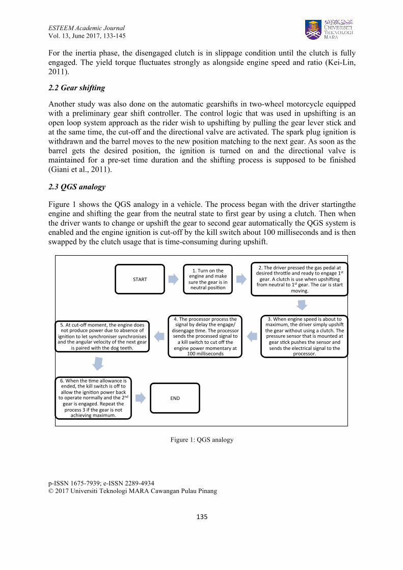
Figure 1 shows the QGS analogy in a vehicle. The process began with the driver startingthe engine and shifting the gear from the neutral state to first gear by using a clutch. Then when the driver wants to change or upshift the gear to second gear automatically the QGS system is enabled and the engine ignition is cut-off by the kill switch about 100 milliseconds and is then swapped by the clutch usage that is time-consuming during upshift.
Figure 1: QGS analogy
START
1. Turn on the engine and make sure the gear is in neutral posi;on
2. The driver pressed the gas pedal at desired thro>le and ready to engage 1st gear. A clutch is use when upshiBing
from neutral to 1st gear. The car is start moving.
3. When engine speed is about to maximum, the driver simply upshiB the gear without using a clutch. The pressure sensor that is mounted at gear s;ck pushes the sensor and sends the electrical signal to the
processor.
4. The processor process the signal by delay the engage/
disengage ;me. The processor sends the processed signal to a kill switch to cut off the
engine power momentary at 100 milliseconds
5. At cut-‐off moment, the engine does not produce power due to absence of igni;on to let synchroniser synchronises and the angular velocity of the next gear
is paired with the dog teeth.
6. When the ;me allowance is ended, the kill switch is off to allow the igni;on power back to operate normally and the 2nd gear is engaged. Repeat the process 3 if the gear is not
achieving maximum.
END

ESTEEM Academic Journal Vol. 13, June 2017, 133-145
p-ISSN 1675-7939; e-ISSN 2289-4934 © 2017 Universiti Teknologi MARA Cawangan Pulau Pinang
136
2.4 Shift sequence
To get a steady shift operation in shift sequence, five steps of the shift sequence as shown in Figure 2 are followed. The sequence starts with setting the transferred torque to zero to allow the teeth of the connecting gear and shaft to disengage. Then it was moving the dog teeth ring to a neutral position between all individual gears where the input and output shaft are mechanically disconnected from each other. Then the synchronizer synchronises the speed of the shaft and next gear by using this mechanically disconnected state. The gear is engaged when the velocity of the next gear is matched with the dog teeth. At this state, torque can again be transferred and the shift sequence is completed (Bergman & Byrhult, 2009).
Figure 2: Shift sequence analogy
3.0 METHODOLOGY
The QGS and CTS were sketched into a schematic diagram that adapts the QGS system into the vehicle CTS by developing the block diagram. Each of the block diagram represents the vehicle components and the automotive system. Figure 3 and Figure 4 show the CTS components and a QGS mechanism activated respectively. Note that the black lines represent a mechanical signal linked to the model to show the relationship between the function of each of the blocks. The gold-coloured arrow line represents the directional of electrical signal output to the next block. The mechanism started when the engine speed reached the maximum speed, where the driver pulled the gear lever for upshift and at a certain angle, a gear lever hit the pressure switch. A pressure switch is an analogue signal that triggers the motion from the gear lever at a certain distance and transmits the electrical signal to the microprocessor.
Set torque to zero
Disengage gear Synchronize Engage new
gear Apply torque

ESTEEM Academic Journal Vol. 13, June 2017, 133-145
p-ISSN 1675-7939; e-ISSN 2289-4934 © 2017 Universiti Teknologi MARA Cawangan Pulau Pinang
137
Figure 3: Conventional transmission components
Figure 4: QGS mechanism when activated
The grey region of the block diagrams in Figure 4 shows the inactive activity when the QGS mechanism was activated. It shows that there was no clutch usage when the QGS was activated.
3.1 Modelling the vehicle transmission components in Matlab Simulink
Before the simulation was prepared, the initial conditions of the vehicle were established and several assumptions were made before modelling the vehicle transmission components in Matlab Simulink. First, both of the vehicles were set in infinite length of the straight track and both of the vehicle time allowances was set for the duration of 60 seconds. Then, the average time taken for change gear for CTS vehicle was obtained during an actual event of the race from neutral to 4th gear and the time data was translated to represent a synchroniser signals shown in Figure 7. For QGS, the method for acquiring the average time taken for changing gear is the same for changing the gear from Neutral state to 1st gear due to the clutch being applied for changing the gear from Neutral to 1st gear. However, for 2nd to 4th gear, the clutch
LEGEND Mechanical signal Electrical signal

ESTEEM Academic Journal Vol. 13, June 2017, 133-145
p-ISSN 1675-7939; e-ISSN 2289-4934 © 2017 Universiti Teknologi MARA Cawangan Pulau Pinang
138
was not applicable due to QGS system mechanism being activated. The time data was translated to represent a synchroniser signals shown in Figure 6.
For simulation, Simscape driveline offers component libraries for modelling and simulation both rotational and translational mechanical system. To build this model, an example from the local model files named vehicle manual transmission was used as the main reference (MathWorks, 2016). Figure 5 shows the QGS model developed from schematic diagram into Simulink environment.
Figure 5: QGS system in vehicle with manual transmission system
The input of this system is inside the System Inputs subsystem. It contains six signals and each signal represent a throttle input, clutch input, and four signals of the different synchroniser inputs respectively. These signals are shown in Figure 6.
Figure 6: Combined system input signal for QGS model
N I II III IV

ESTEEM Academic Journal Vol. 13, June 2017, 133-145
p-ISSN 1675-7939; e-ISSN 2289-4934 © 2017 Universiti Teknologi MARA Cawangan Pulau Pinang
139
Then the signal for normal clutch usage is modelled as shown in Figure 7. The input clutch signal presented the entire change gear time.
Figure 7: Combined system input for CTS model
The difference for these QGS and CTS by comparing both Figure 6 and Figure 7 are the clutch usage and time duration for gear upshift. In CTS, the clutch was applied in order to allow gear upshift for every sequence while QGS used only to change gear from Neutral state to 1st gear. Table 1 shows shift sequence time range of vehicle both CTS and QGS. The timing for gear upshift was done when the engine rpm follow each other (refer to Figure 8 as the level for both QGS and CTS are same) to ensure both of these vehicles were fair in upshift time. The timing of gear upshift for QGS and CTS were the same for Neutral and 1st gear. For 2nd gear onwards, the timing of gear upshift did not follow each other as time lag occurred due to QGS system being a consistent and fast response in upshifting Another reason is due to the inconsistent driver behaviour during upshift due to applying a clutch.
Shift sequence
Gear time range (seconds) QGS
Gear time range
(seconds) CTS
Gear time duration (T2-T1) (seconds) QGS
Gear time duration (T2-T1) (seconds)
CTS
Time Different |(CTS – QGS)|
(seconds) Neutral (N) 0.00 – 3.95 0.00 – 3.95 3.95 3.95 0 1st gear (I) 3.95 – 10.70 3.95 – 10.70 6.75 6.75 0 2nd gear (II) 10.80 – 16.20 11.30 – 17.30 5.40 6.00 0.6 3rd gear (III) 16.21 – 26.50 17.90 – 29.10 10.29 11.20 0.91 4th gear (IV) 26.60 – 60.00 30.05 – 60.00 33.40 29.95 3.45
Table 1: Shift sequence time range of vehicle with CTS
I N II III IV

ESTEEM Academic Journal Vol. 13, June 2017, 133-145
p-ISSN 1675-7939; e-ISSN 2289-4934 © 2017 Universiti Teknologi MARA Cawangan Pulau Pinang
140
3.2 The system input parameters
The system input parameters were set into the simulation and as shown in Table 2 is for a vehicle body, Table 3 is for the engine, Table 4 is for the clutch, and Table 5 is for the transmission. The model parameterization for the engine is used in normalised 3rd-order polynomial matched to peak power. The asterisk sign (*) show the input value is an assumption made.
Vehicle parameter
Mass (kg) 250
Number of wheels per axle 2
Horizontal distance from CG to front axle (m)* 1.4
Horizontal distance from CG to rear axle (m)* 1.6
Frontal area (m2)* 1
Drag coefficient* 0.4
Initial velocity (m/s) 0
Table 2: Vehicle body
Engine torque Maximum power (kW) 5.64 Speed at maximum power (rpm) 7500 Maximum speed (rpm) 8500* Stall speed (rpm) 200
Engine dynamics Inertia (kg m2)* 0.01 Initial velocity (rpm) 800
Table 3: Engine input parameter
Clutch dimension* Effective torque radius (mm) 300
Clutch friction* Kinetic friction coefficient 0.46 Static friction coefficient 0.5 Velocity tolerance (rad/s) 0.001
Table 4: Clutch input parameter
Gear ratio 1st gear 2.615 2nd gear 1.555 3rd gear 1.136 4th gear 0.916 Primary reduction 4.059 Final reduction 2.642
Table 5: Transmission system
ESTEEM Academic Journal Vol. 13, June 2017, 133-145
p-ISSN 1675-7939; e-ISSN 2289-4934 © 2017 Universiti Teknologi MARA Cawangan Pulau Pinang
141
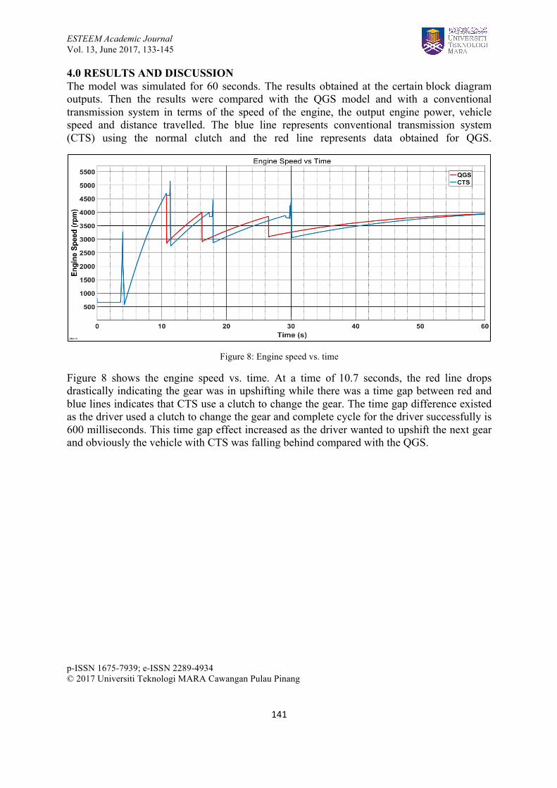
4.0 RESULTS AND DISCUSSION The model was simulated for 60 seconds. The results obtained at the certain block diagram outputs. Then the results were compared with the QGS model and with a conventional transmission system in terms of the speed of the engine, the output engine power, vehicle speed and distance travelled. The blue line represents conventional transmission system (CTS) using the normal clutch and the red line represents data obtained for QGS.
Figure 8: Engine speed vs. time
Figure 8 shows the engine speed vs. time. At a time of 10.7 seconds, the red line drops drastically indicating the gear was in upshifting while there was a time gap between red and blue lines indicates that CTS use a clutch to change the gear. The time gap difference existed as the driver used a clutch to change the gear and complete cycle for the driver successfully is 600 milliseconds. This time gap effect increased as the driver wanted to upshift the next gear and obviously the vehicle with CTS was falling behind compared with the QGS.

ESTEEM Academic Journal Vol. 13, June 2017, 133-145
p-ISSN 1675-7939; e-ISSN 2289-4934 © 2017 Universiti Teknologi MARA Cawangan Pulau Pinang
142
Figure 9: Engine power vs. time
Figure 9 shows the engine power curve vs. time for both using QGS and CTS. The QGS system works through the cutting-off engine ignition before changing gear. During gear changing, there was no power produced from the engine. This is because the torque held by the transmission system needed to be eliminated. In such condition, the gear to be transferred was easily engaged. The time gap from engine ignition cut-off to the gear was constantly 100 milliseconds. However, CTS worked differently as it required the clutch to be used when changing gear. This resulted in a bigger time gap of approximately 600 milliseconds. The engine power dropped at each gear change due to different gear ratio. However, there was a significant engine power drop for CTS after an instant power shoot. This happened because of clutch slip, as the power increased instantaneously from zero power during upshifting. This did not happen to QGS system because no clutch was engaged.
ESTEEM Academic Journal Vol. 13, June 2017, 133-145
p-ISSN 1675-7939; e-ISSN 2289-4934 © 2017 Universiti Teknologi MARA Cawangan Pulau Pinang
143
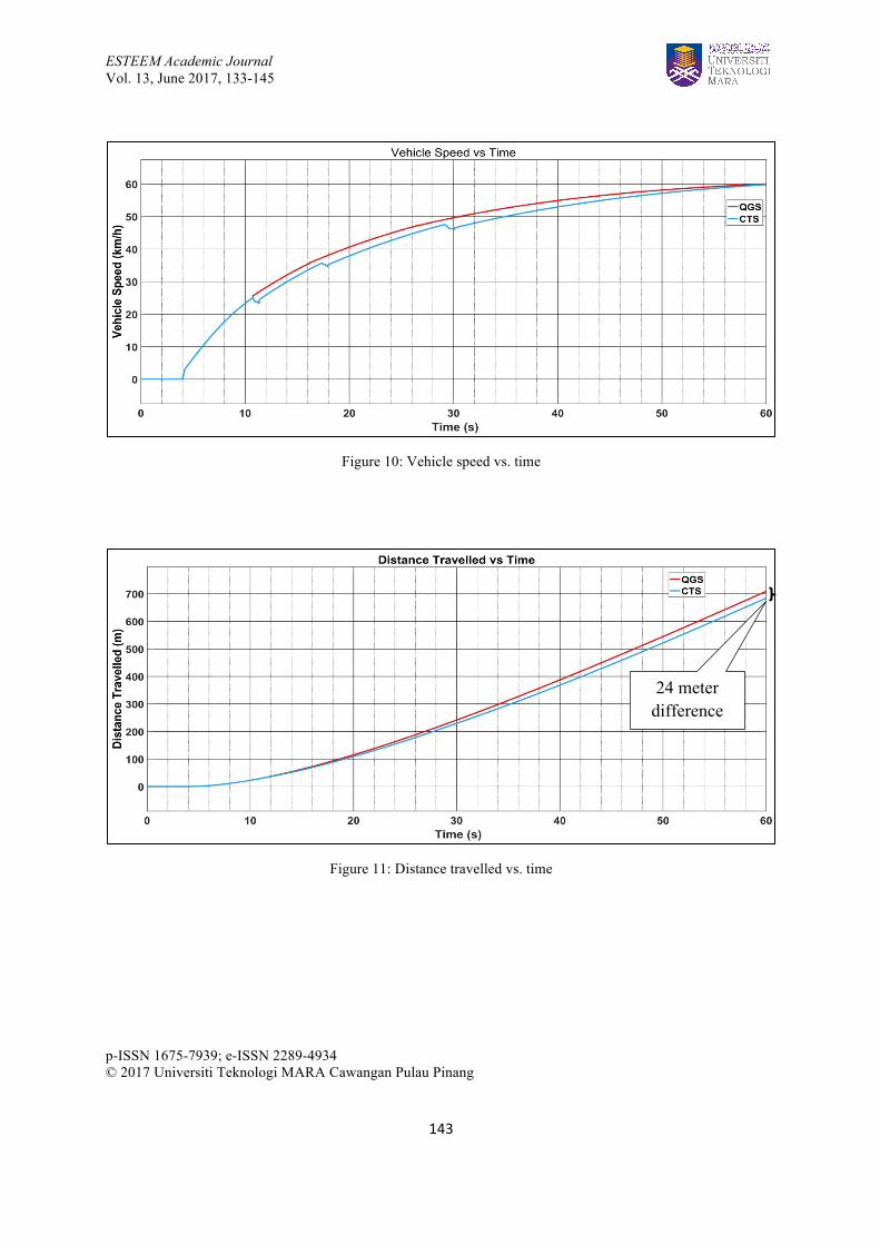
Figure 10: Vehicle speed vs. time
Figure 11: Distance travelled vs. time
24 meter difference

ESTEEM Academic Journal Vol. 14, June 2017, 133-145
p-ISSN 1675-7939; e-ISSN 2289-4934 © 2017 Universiti Teknologi MARA Cawangan Pulau Pinang
144
Figure 10 shows the speed comparison between a vehicle with QGS and CTS. It can be seen that QGS gave a smooth speed curve over the normal clutch usage. The speed drop in every shifting region was due to the clutch usage. It gave a disadvantage in term of acceleration as both of the vehicles were always full throttle right after they change gear. At the time 60 sec, the speed of both vehicles matched together.
Figure 11 shows the distance travelled for both vehicles. At the initial time, both vehicles moved in the same distance until they upshifted to the second gear. In this moment, a vehicle with QGS started to move away from the vehicle with CTS. Then, after 60 seconds, the distance between vehicles with QGS was approximately 24 meters leading from the vehicle with CTS.
5.0 CONCLUSION AND RECOMMENDATIONS
The QGS system shows that by reducing the time consumed due to the clutch usage can provide a necessary booster to the racing car. It is crucial in the racing environment as the speed and acceleration are the main factors to achieve the best possible vehicle performances. Compared to CTS, the QGS system obviously gave an advantage when racing at a short race track with corners. Based on this study, such condition requires constant gear changing especially when overtaking other racing cars. The QGS also improves the distance travelled compared to CTS, therefore, a vehicle using a QGS can have a higher chance to win the race. Study on the effects of the synchroniser in a transmission system for the QGS could improve the system behaviour and performances.
REFERENCES
Bergman, A., & Byrhult, P. (2009). Automated shifting of a manual sequential transmission in a hybrid vehicle.
Dynojet. (2016). Power Commander Quick Shifter. Erjavec, Jack; Thompson, R. (2015). Automotive Technology - A System Approach. (L.
Costakis, Ed.) (6th ed.). New York: Cengage Learning. Giani, P., Todeschini, F., Corbetta, S., Tanelli, M., Savaresi, S. M., & Fabbri, L. (2011).
Control-oriented analysis and quality assessment of gear shifting in motorcycles. Proceedings of the IEEE International Conference on Control Applications, 326–331. https://doi.org/10.1109/CCA.2011.6044448
Harald, Naunheimer; Bertsche, Bernd; Ryborz, Joachim; Novak, W. (1994). Automotive
Transmissions - Fundamentals, Selection, Design and Application (Second Edi). London New York: Springer Heidelberg Dordrecht.

ESTEEM Academic Journal Vol. 14, June 2017, 133-145
p-ISSN 1675-7939; e-ISSN 2289-4934 © 2017 Universiti Teknologi MARA Cawangan Pulau Pinang
145
Kei-Lin, K. (2011). Simulation and Analysis of the Shift Process for an Automatic
Transmission. International Journal of Mechanical, Aerospace, Industrial, Mechatronic and Manufacturing Engineering, 5(4), 785–791.
MathWorks. (2016). Vehicle with Manual Transmission. Poovey, B. (2014). How Do Motorcycle Quick Shifters Work? Wan, M. S. (2004). Close-circle Control System of Automatic Transmission. Journal of
Nanjing Forestry University, Science Vo.