Embed Size (px)
Citation preview
Improving Active-power Transfer Capacity ofVirtual Synchronous Generator in Weak Grid
Shuan Dong and Yu Christine ChenDepartment of Electrical and Computer Engineering
The University of British ColumbiaVancouver, BC, Canada
Email: [email protected], [email protected]
Abstract—The virtual synchronous generator (VSG) is apower-electronic controller that mimics the dynamic behaviourof synchronous generators. It is a promising technology to enableintegration of renewable energy conversion systems under weak-grid conditions. By providing virtual inertia, the VSG improvessystem stability. However, under weak-grid conditions, systemstability may also be adversely affected by the VSG exceeding itsactive-power transfer capacity, leading to a phenomenon knownas voltage instability. In this paper, we highlight this problemvia simulations conducted for a microgrid test system. Then,we offer analytical justification for the mechanism and rootcause of the observed voltage instability. We further propose twocountermeasures to improve the active-power transfer capacity.The first is based on existing VSG capabilities so that no newcomponents are needed in the controller, and the second requiresadditional components but enables full use of the VSG capacity.
I. INTRODUCTION
To contend with tremendous growth in renewable energyintegration, the modern power system faces numerous chal-lenges with respect to power availability and quality [1]. Theseinclude notable reduction in system inertia because, unlikeconventional turbine-based generators, inverter-interfaced re-newable energy sources (RESs) have low or no inertia. Oneway to address this problem is to design the inverter power-electronic controller so that it emulates dynamics arisingfrom synchronous generators (SGs) and in turn providesvirtual inertia to the grid—a concept known as virtual syn-chronous generator (VSG) [2]–[12]. The VSG can also enablefrequency- and voltage-droop control, which leads to grid-stability improvements. Moreover, unlike conventional controlmethods such as vector-current control, VSGs operate wellunder weak-grid conditions, which is ideal in the integrationof RESs that are oftentimes geographically situated in remoteareas with weak transmission links to urban load centres [13].
Owing to the many benefits that VSGs offer in renewableenergy integration, various aspects of VSGs have been exten-sively studied and improved over the past decade [2]–[8]. Forexample, [2] increases the VSG control freedom such that theRES has freely adjustable damping, [3] equips the VSG withself-synchronization capability such that the RES achievesplug-and-play operation, and [4] limits the VSG output currentduring fault conditions and endows the RES with low-voltage
ride-through capability. Also, [5] and [6] improve the VSGtransient stability and the VSG reactive-power sharing perfor-mance, respectively. Furthermore, to facilitate the renewableenergy integration using VSGs, [7] proposed a VSG-basedwind turbine controller, and [8] presents a VSG-based multi-terminal HVDC design that are able to integrate large-scalerenewable energy conversion systems. For VSGs that areweakly connected to the rest of the grid, which is typically thecase for remotely located RESs, [9] maintains a safe stabilitymargin by reducing the controller bandwidth, [10] stabilizesthe system by appending a supplementary nonlinear controller,and [11] improves the system stability by reducing the high-frequency amplification effect.
An aspect of the VSG that has not been thoroughly investi-gated in the literature is the active-power transfer capacity ofVSG-controlled RESs operating under weak-grid conditions.If the actual active power delivered from the RES to the loadcentre exceeds the transfer capacity, the system would notconverge to a viable power-flow solution, and this leads to so-called voltage instability [14]. Conventionally, voltage stabilityis often compromised by heavy loading conditions, and theimpacts of grid voltage variations on the voltage stability hasbeen studied in [12]. In our setting, however, loss of stabilitystems from greater VSG active-power output than that canbe delivered to the rest of the system. This paper reveals animportant cause of voltage instability in VSG-integrated powersystems. Particularly, we provide analysis for the mechanismof voltage instability under weak-grid conditions. We furtherpropose two countermeasures to improve VSG active-powertransfer capacity: (i) activate the voltage-droop controller,which requires the VSG to provide more reactive-poweroutput, and (ii) use additional reactive-power compensationdevices, so as to enable full use of the VSG capacity. It isworth noting that though voltage droop control and reactive-power compensation have been extensively studied before,they have not been used to improve VSG active-power transfercapacity under weak-grid conditions.
The remainder of the paper is organized as follows. InSection II, we describe a VSG-connected microgrid test systemand demonstrate the necessity of studying VSG active-powertransfer capacity. Analysis is provided in Section III, basedon which we develop methods to improve the active-powertransfer capacity. In Section IV, we verify the effectiveness of978-1-7281-1842-0/19/$31.00 c©2019 IEEE
proposed solutions via numerical simulations. Section V offersconcluding remarks and directions for future work.
II. PRELIMINARIES
In this section, we first provide an overview of the VSGdesign. Thereafter, we introduce a microgrid test system, inwhich a VSG operates under weak-grid conditions since itis connected to the external grid via a long transmissionline. Finally, using this system as an example, we show thenecessity of studying the VSG active-power transfer capacity.
A. Virtual Synchronous GeneratorAs shown in Fig. 1, the active- and reactive-power loops
of the VSG regulate its active-power output Pt and reactive-power output Qt by varying its rotor angle θg and excitationflux ψf , respectively. Also, depending on the statuses ofSwitches 1 and 2, denoted by S1 and S2, respectively, the VSGcan achieve frequency- and voltage-droop controls (Si = 1 ifSwitch i is ON, and Si = 0 if Switch i is OFF, i = 1, 2).Spefically, as shown in Fig. 1(b), the dynamics of the VSGreactive-power loop (RPL) in Fig. 1(b) is described by
Kgdψfdt
= (Q?t −Qtf ) + S2
√2
3Dq(U
?t − Utf ), (1)
where the coefficient Kg determines the RPL response speed,Q?t and U?t , respectively, denote the reference value of theVSG reactive-power output Qt and output voltage magni-tude Ut, and Qtf and Utf , respectively, represent the filteredsignals of Qt and Ut. In (1), the voltage droop coefficient Dq
is tuned based on the required amount of variation in Qtfor certain change in Ut. In the remainder of paper, weomit the dynamics of the low-pass filters (LPFs) in Fig. 1and assume that Qtf ≈ Qt and Utf ≈ Ut. We note thatneglecting their dynamics facilitates our analysis without lossof accuracy, since voltage stability, which limits the VSGactive-power transfer capacity, acts on a slower time-scaleand is usually analyzed via static models (e.g., PV and QVcurves, continuation power flow, modal analysis, etc.) that areindependent of these dynamics [14].
As for the VSG active-power loop (APL) in Fig. 1(a), itemulates SG rotor dynamics described by
Jgdωgdt
=P ?tωN−Tef −Df
d
dt
(Tef
ψff
)−S1Dp
(ωg−ω?g
), (2)
dθgdt
=ωg, (3)
where Jg denotes the inertia constant, P ?t the active-powerreference value, ωN the rated angular frequency, and Tef thefiltered signal of the VSG electromagnetic torque Te. In (2),the terms Df
ddt
(Tef
ψff
)and S1Dp
(ωg−ω?g
), respectively, rep-
resent the damping correction loop, which adjusts the APLdamping ratio, and the switchable frequency-droop controller,which achieves primary frequency control.
As shown in Fig. 1, with the RPL output ψf as well as therotating speed ωg and the rotor angle θg from the APL, weobtain the VSG inner voltage eg with the line-to-line RMSvalue Eg =
√3/2ωgψf .
Fig. 1. Virtual synchronous generator augmented with damping correctionloop [2]. (a) Active-power loop. (b) Reactive-power loop.
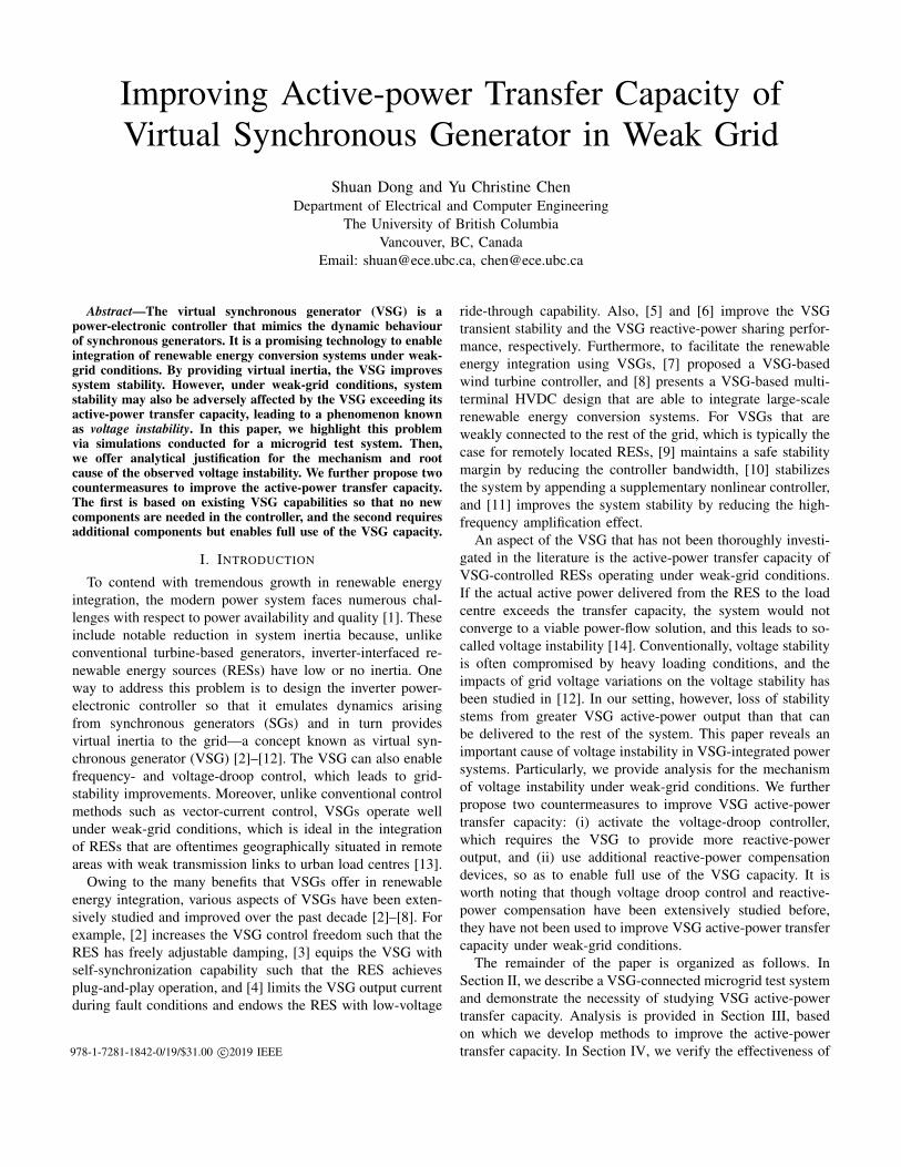
B. Test System
Our aim is to study the active-power transfer capacity ofthe VSG under weak-grid conditions. In order to do so, weconsider the microgrid test system shown in Fig. 2, wherea VSG and two SGs (SG1 and SG2) provide power, behindthree transformers, to three constant-impedance loads (Load1,Load2, and Load3). Furthermore, the VSG is connected tothe rest of the system via a long transmission line (Line47).This setup is representative of the scenario in which VSG-interfaced devices (e.g., RESs and battery storage) must belocated farther away from load centres due to geographical and
Fig. 2. Microgrid test system used to demonstrate the active-power transfercapacity of the virtual synchronous generator under weak-grid conditions.

Fig. 3. Without voltage-droop controller: system dynamics caused by increasing the VSG active-power reference P ?t from 0 to 0.5 (case I) and 0.7 MW
(case II), respectively. (a)(b) Case I. (c)(d) Case II.
safety considerations. Note that to stabilize grid frequency andregulate grid voltage, both SGs are equipped with a modifiedWoodward governor (see Fig. 9) and a standard excitationcontroller (see Fig. 10). We refer readers to Appendices A–Cfor values used for VSG, SG, and network parameters.
C. Problem Statement
With the the VSG controller and system described above,we motivate the necessity of studying the VSG active-powertransfer capacity under weak-grid conditions via an example.
Example 1 (Motivation). In this example, we use the systemin Fig. 2 to study the active-power transfer capacity of theVSG by increasing its active-power reference value P ?t from 0to 0.5 (case I) and 0.7 MW (case II) at t = 5.0 s. In bothcases, we set Q?t to be zero and deactivate frequency- andvoltage-droop controls, which results in unity power factorand enables Pt (Qt) to track P ?t (Q?t ) without steady-steadyerror. In case I, as shown in Figs. 3(a), the VSG active-poweroutput Pt (trace (i)) grows from 0 to 0.5 MW at t = 5.0 sfollowing the change in P ?t . Also, as depicted in Fig. 3(b), theVSG inner voltage Eg (trace (i)) decreases from 6.5 to 6.1 kVand remains stable. On the other hand, as shown in Fig. 3(c),following the change in P ?t from 0 to 0.7 MW, the VSGoutputs initially converge to the desired setpoints but thenbegins to oscillate wildly about 20 s after the power-referencechange. As shown in Fig. 3(d), the VSG inner voltage Eggradually decreases beginning from t = 5.0 s and finallycollapses at t = 24.0 s. After this moment, as shown inFig. 3(c), Pt and Qt becomes oscillatory and they are unableto converge to desired P ?t and Q?t .
Based on the observations made in Example 1, we aremotivated to seek analytical justification for the oscillatorybehaviour in Fig. 3(c) and further propose countermeasures toprevent it even for large active-power transfer.
Fig. 4. Equivalent circuit of the system in Fig. 2 as seen from the VSG.
III. VSG ACTIVE-POWER TRANSFER CAPACITY
In this section, we provide analytical justification for voltageinstability due to violation of VSG active-power transfercapacity. Then based on the analysis, we propose countermea-sures to improve the active-power transfer capacity of the VSGand avoid voltage instability in the system.
A. Analysis of VSG Active-power Transfer Capacity
Our analysis of the VSG active-power transfer capacity be-gins with the derivation of an equivalent single-VSG infinite-bus system shown in Fig. 4, in which the infinite bus voltageis U∞ = 6.8 kV, the LCL filter impedance is ZLCL ≈jXs = j2.72 Ω, and the equivalent impedance is Ze ≈ jXe =j33.62 Ω (we retain only the reactance Xe Xs, since thenetwork in Fig. 2 is assumed to be predominantly inductive).A full exposition of the derivation can be found in [15]. Let Xt
denote the total system reactance, i.e., Xt = Xs + Xe. Thenthe VSG active-power output Pt and reactive-power output Qtcan be expressed as, respectively,
Pt =EgU∞ sin θg∞
Xt, Qt ≈
E2g
Xt− EgU∞ cos θg∞
Xt, (4)
where U∞ denotes the grid voltage, and θg∞ denotes thephase-angle difference between Eg and U∞. By eliminat-ing θg∞ from (4), we get the following expression:
E4g − (2XtQt + U2
∞)E2g +X2
t (P 2t +Q2
t ) = 0, (5)
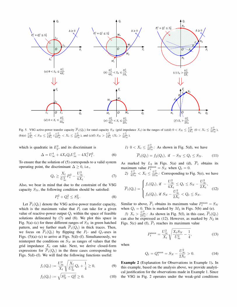
Fig. 5. VSG active-power transfer capacity P t(Qt) for rated capacity SN (grid impedance Xt) in the ranges of (a)(d) 0 < SN ≤ U2∞
4Xt(0 < Xt ≤
U2∞
4SN),
(b)(e) U2∞
4Xt< SN ≤ U2
∞2Xt
( U2∞
4SN< Xt ≤
U2∞
2SN), and (c)(f) SN >
U2∞
2Xt(Xt >
U2∞
2SN).
which is quadratic in E2g , and its discriminant is
∆ = U4∞ + 4XtQtU
2∞ − 4X2
t P2t . (6)
To ensure that the solution of (5) corresponds to a valid systemoperating point, the discriminant ∆ ≥ 0, i.e.,
Qt ≥Xt
U2∞P 2t −
U2∞
4Xt. (7)
Also, we bear in mind that due to the constraint of the VSGcapacity SN , the following condition should be satisfied:
P 2t +Q2
t ≤ S2N . (8)
Let P t(Qt) denote the VSG active-power transfer capacity,which is the maximum value that Pt can take for a givenvalue of reactive-power output Qt within the space of feasiblesolutions delineated by (7) and (8). We plot this space inFig. 5(a)–(c) for three different ranges of SN in green hatchedpattern, and we further mark P t(Qt) in thick traces. Then,we focus on P t(Qt) by flipping the Pt- and Qt-axes inFigs. (5)(a)–(c) to arrive at Figs. 5(d)–(f). Simultaneously, wereinterpret the conditions on SN as ranges of values that thegrid impedance Xt can take. Next, we derive closed-formexpressions for P t(Qt) in the three cases corresponding toFigs. 5(d)–(f). We will find the following functions useful:
f1(Qt) :=U2∞Xt
√Xt
U2∞Qt +
1
4≥ 0, (9)
f2(Qt) :=√S2N −Q2
t ≥ 0. (10)
1) 0 < Xt ≤ U2∞
4SN: As shown in Fig. 5(d), we have
P t(Qt) = f2(Qt), if − SN ≤ Qt ≤ SN . (11)
As marked by L2 in Figs. 5(a) and (d), P t obtains itsmaximum value Pmax
t = SN when Qt = 0.2) U2
∞4SN
< Xt ≤ U2∞
2SN: Corresponding to Fig. 5(e), we have
P t(Qt) =
f1(Qt), if − U2
∞4Xt
≤ Qt ≤ SN −U2∞
2Xt,
f2(Qt), if SN −U2∞
2Xt< Qt ≤ SN .
(12)
Similar to above, P t obtains its maximum value Pmaxt = SN
when Qt = 0. This is marked by M3 in Figs. 5(b) and (e).3) Xt >
U2∞
2SN: As shown in Fig. 5(f), in this case, P t(Qt)
can also be expressed as (12). However, as marked by N2 inFigs. 5(c) and (f), P t reaches its maximum value
Pmaxt =
U2∞Xt
√XtSNU2∞− 1
4, (13)
when
Qt = Qmaxt = SN −
U2∞
2Xt> 0. (14)
Example 2 (Explanation for Observations in Example 1). Inthis example, based on the analysis above, we provide analyti-cal justification for the observations made in Example 1. Sincethe VSG in Fig. 2 operates under the weak-grid conditions
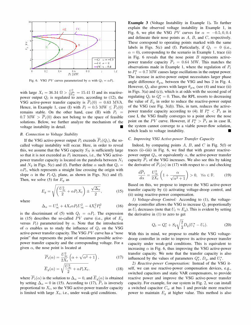
Fig. 6. VSG PV curves parameterized by α with Qt = αPt.
with large Xt = 36.34 Ω >U2
∞2SN
= 15.41 Ω and its reactive-power output Qt is regulated to zero, according to (12), theVSG active-power transfer capacity is P t(0) = 0.63 MVA.Hence, in Example 1, case (I) with Pt = 0.5 MW ≤ P t(0)remains stable. On the other hand, case (II) with Pt =0.7 MW > P t(0) does not belong to the space of feasiblesolutions. Below, we further analyze the mechanism of thevoltage instability in detail.
B. Connection to Voltage Stability
If the VSG active-power output Pt exceeds P t(Qt), the so-called voltage instability will occur. Here, in order to revealthis, we assume that the VSG capacity SN is sufficiently largeso that it is not exceeded as Pt increases, i.e., the VSG active-power transfer capacity is located on the parabola between N1
and N2 in Figs. 5(c) and (f). Further define α such that Qt =αPt, which represents a straight line crossing the origin withslope α in the Pt-Qt plane, as shown in Figs. 5(c) and (f).Then, we solve (5) for Eg as
Eg =
√(U2∞2
+ αPtXt
)±√
∆α
2, (15)
where∆α = U4
∞ + 4XtαPtU2∞ − 4X2
t P2t (16)
is the discriminant of (5) with Qt = αPt. The expressionin (15) describes the so-called PV curve (i.e., plot of Egversus Pt) parameterized by α. Note that the introductionof α enables us to study the influence of Qt on the VSGactive-power transfer capacity. The VSG PV curve has a “nosepoint” that represents the point of maximum possible active-power transfer capacity and the corresponding voltage. For agiven α, the nose point is located at
P t(α) =U2∞
2Xt
(α+
√α2 + 1
), (17)
Eg(α) =
√U2∞2
+ αPtXt. (18)
where P t(α) is the solution to ∆α = 0, and Eg(α) is obtainedby setting ∆α = 0 in (15). According to (17), P t is inverselyproportional to Xt, so the VSG active-power transfer capacityis limited with large Xt, i.e., under weak-grid conditions.
Example 3 (Voltage Instability in Example 1). To furtherexplain the observed voltage instability in Example 1, inFig. 6, we plot the VSG PV curves for α = −0.5, 0, 0.4and delineate their nose points as A, B, and C, respectively.These correspond to operating points marked with the samelabels in Figs. 5(c) and (f). Particularly, if Qt = 0 (i.e.,α = 0), corresponding to the scenario in Example 1, trace (ii)in Fig. 6 reveals that the nose point B represents active-power transfer capacity P t = 0.64 MW. This matches theobservations made in Example 1, where the regulation of Ptto P ?t = 0.7 MW causes large oscillations in the output power.The increase in active-power output necessitates larger phaseangle difference θg∞ between the VSG and bus 2 in Fig. 4.However, Qt also grows with larger θg∞ (see (4) and trace (ii)in Figs. 3(a) and (c)), which is at odds with the second goal ofregulating Qt to Q?t = 0. Thus, the RPL resorts to decreasingthe value of Eg in order to reduce the reactive-power outputof the VSG (see Fig. 3(d)). This, in turn, reduces the active-power transfer capacity according to (4). If P ?t < P t as incase I, the VSG finally converges to a point above the nosepoint on the PV curve. However, if P ?t > P t as in case II,the system cannot converge to a viable power-flow solution,which leads to voltage instability.
C. Improving VSG Active-power Transfer Capacity
Indeed, by comparing points A, B, and C in Fig. 5(f) ortraces (i)–(iii) in Fig. 6, we find that with greater reactive-power output Qt, or equivalently α, the active-power transfercapacity P t of the VSG increases. We also see this by takingthe derivative of P t(α) in (17) with respect to α and checking
dP tdα
=U2∞
2Xt
(1 +
α√α2 + 1
)> 0, ∀α ∈ R. (19)
Based on this, we propose to improve the VSG active-powertransfer capacity by (i) activating voltage-droop control, and(ii) using reactive-power compensation.
1) Voltage-droop Control: According to (1), the voltage-droop controller allows the VSG to increase Qt proportionallyas Ut decreases (note that Ut ≈ Eg). This is evident by settingthe derivative in (1) to zero to get
Qt = Q?t + S2
√2
3Dq(U
?t − Ut). (20)
With this in mind, we propose to enable the VSG voltage-droop controller in order to improve its active-power transfercapacity under weak-grid conditions. This is equivalent toincreasing α in Fig. 6, thus improving the VSG active-powertransfer capacity. We note that the transfer capacity is alsoinfluenced by the values of parameters Q?t , Dq , and U?t .
2) Reactive-power Compensation: Instead of the VSG it-self, we can use reactive-power compensation devices, e.g.,switched capacitors and static VAR compensators, to providereactive power and improve the VSG active-power transfercapacity. For example, for our system in Fig. 2, we can installa switched capacitor Cw at bus 1 and provide more reactivepower to maintain Eg at higher value. This method is also
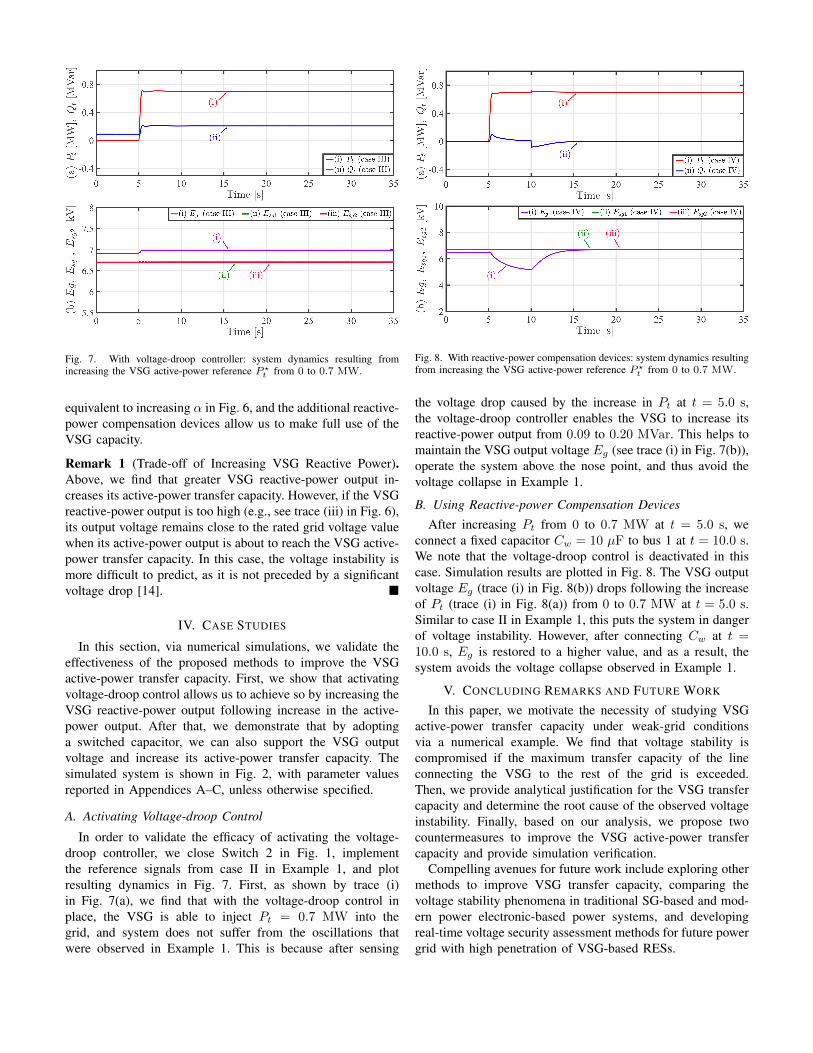
Fig. 7. With voltage-droop controller: system dynamics resulting fromincreasing the VSG active-power reference P ?
t from 0 to 0.7 MW.
equivalent to increasing α in Fig. 6, and the additional reactive-power compensation devices allow us to make full use of theVSG capacity.
Remark 1 (Trade-off of Increasing VSG Reactive Power).Above, we find that greater VSG reactive-power output in-creases its active-power transfer capacity. However, if the VSGreactive-power output is too high (e.g., see trace (iii) in Fig. 6),its output voltage remains close to the rated grid voltage valuewhen its active-power output is about to reach the VSG active-power transfer capacity. In this case, the voltage instability ismore difficult to predict, as it is not preceded by a significantvoltage drop [14].
IV. CASE STUDIES
In this section, via numerical simulations, we validate theeffectiveness of the proposed methods to improve the VSGactive-power transfer capacity. First, we show that activatingvoltage-droop control allows us to achieve so by increasing theVSG reactive-power output following increase in the active-power output. After that, we demonstrate that by adoptinga switched capacitor, we can also support the VSG outputvoltage and increase its active-power transfer capacity. Thesimulated system is shown in Fig. 2, with parameter valuesreported in Appendices A–C, unless otherwise specified.
A. Activating Voltage-droop Control
In order to validate the efficacy of activating the voltage-droop controller, we close Switch 2 in Fig. 1, implementthe reference signals from case II in Example 1, and plotresulting dynamics in Fig. 7. First, as shown by trace (i)in Fig. 7(a), we find that with the voltage-droop control inplace, the VSG is able to inject Pt = 0.7 MW into thegrid, and system does not suffer from the oscillations thatwere observed in Example 1. This is because after sensing
Fig. 8. With reactive-power compensation devices: system dynamics resultingfrom increasing the VSG active-power reference P ?
t from 0 to 0.7 MW.
the voltage drop caused by the increase in Pt at t = 5.0 s,the voltage-droop controller enables the VSG to increase itsreactive-power output from 0.09 to 0.20 MVar. This helps tomaintain the VSG output voltage Eg (see trace (i) in Fig. 7(b)),operate the system above the nose point, and thus avoid thevoltage collapse in Example 1.
B. Using Reactive-power Compensation DevicesAfter increasing Pt from 0 to 0.7 MW at t = 5.0 s, we
connect a fixed capacitor Cw = 10 µF to bus 1 at t = 10.0 s.We note that the voltage-droop control is deactivated in thiscase. Simulation results are plotted in Fig. 8. The VSG outputvoltage Eg (trace (i) in Fig. 8(b)) drops following the increaseof Pt (trace (i) in Fig. 8(a)) from 0 to 0.7 MW at t = 5.0 s.Similar to case II in Example 1, this puts the system in dangerof voltage instability. However, after connecting Cw at t =10.0 s, Eg is restored to a higher value, and as a result, thesystem avoids the voltage collapse observed in Example 1.
V. CONCLUDING REMARKS AND FUTURE WORK
In this paper, we motivate the necessity of studying VSGactive-power transfer capacity under weak-grid conditionsvia a numerical example. We find that voltage stability iscompromised if the maximum transfer capacity of the lineconnecting the VSG to the rest of the grid is exceeded.Then, we provide analytical justification for the VSG transfercapacity and determine the root cause of the observed voltageinstability. Finally, based on our analysis, we propose twocountermeasures to improve the VSG active-power transfercapacity and provide simulation verification.
Compelling avenues for future work include exploring othermethods to improve VSG transfer capacity, comparing thevoltage stability phenomena in traditional SG-based and mod-ern power electronic-based power systems, and developingreal-time voltage security assessment methods for future powergrid with high penetration of VSG-based RESs.
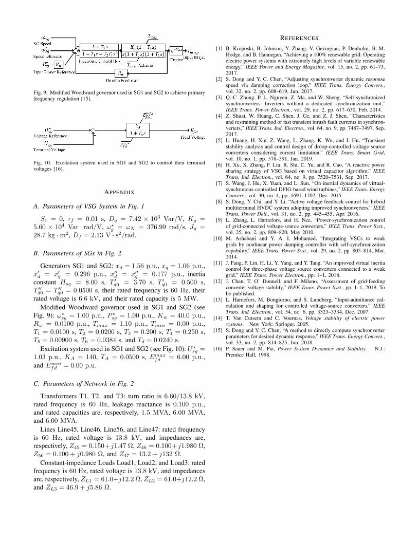
Fig. 9. Modified Woodward governor used in SG1 and SG2 to achieve primaryfrequency regulation [15].
Fig. 10. Excitation system used in SG1 and SG2 to control their terminalvoltages [16].
APPENDIX
A. Parameters of VSG System in Fig. 1
S1 = 0, τf = 0.01 s, Dq = 7.42 × 10³ Var/V, Kg =5.60 × 10⁴ Var · rad/V, ω?g = ωN = 376.99 rad/s, Jg =28.7 kg ·m2, Df = 2.13 V · s2/rad.
B. Parameters of SGs in Fig. 2
Generators SG1 and SG2: xd = 1.56 p.u., xq = 1.06 p.u.,x′d = x′q = 0.296 p.u., x′′d = x′′q = 0.177 p.u., inertiaconstant Hsg = 8.00 s, T ′
d0 = 3.70 s, T ′q0 = 0.500 s,
T ′′d0 = T ′′
q0 = 0.0500 s, their rated frequency is 60 Hz, theirrated voltage is 6.6 kV, and their rated capacity is 5 MW.
Modified Woodward governor used in SG1 and SG2 (seeFig. 9): ω?sg = 1.00 p.u., P ?sg = 1.00 p.u., Kw = 40.0 p.u.,Rw = 0.0100 p.u., Tmax = 1.10 p.u., Tmin = 0.00 p.u.,T1 = 0.0100 s, T2 = 0.0200 s, T3 = 0.200 s, T4 = 0.250 s,T5 = 0.00900 s, T6 = 0.0384 s, and Td = 0.0240 s.
Excitation system used in SG1 and SG2 (see Fig. 10): U?sg =1.03 p.u., KA = 140, TA = 0.0500 s, Emaxfd = 6.00 p.u.,and Eminfd = 0.00 p.u.
C. Parameters of Network in Fig. 2
Transformers T1, T2, and T3: turn ratio is 6.60/13.8 kV,rated frequency is 60 Hz, leakage reactance is 0.100 p.u.,and rated capacities are, respectively, 1.5 MVA, 6.00 MVA,and 6.00 MVA.
Lines Line45, Line46, Line56, and Line47: rated frequencyis 60 Hz, rated voltage is 13.8 kV, and impedances are,respectively, Z45 = 0.150+j1.47 Ω, Z46 = 0.100+j1.980 Ω,Z56 = 0.100 + j0.980 Ω, and Z47 = 13.2 + j132 Ω.
Constant-impedance Loads Load1, Load2, and Load3: ratedfrequency is 60 Hz, rated voltage is 13.8 kV, and impedancesare, respectively, ZL1 = 61.0+j12.2 Ω, ZL2 = 61.0+j12.2 Ω,and ZL3 = 46.9 + j5.86 Ω.
REFERENCES
[1] B. Kroposki, B. Johnson, Y. Zhang, V. Gevorgian, P. Denholm, B.-M.Hodge, and B. Hannegan, “Achieving a 100% renewable grid: Operatingelectric power systems with extremely high levels of variable renewableenergy,” IEEE Power and Energy Magazine, vol. 15, no. 2, pp. 61–73,2017.
[2] S. Dong and Y. C. Chen, “Adjusting synchronverter dynamic responsespeed via damping correction loop,” IEEE Trans. Energy Convers.,vol. 32, no. 2, pp. 608–619, Jun. 2017.
[3] Q.-C. Zhong, P. L. Nguyen, Z. Ma, and W. Sheng, “Self-synchronizedsynchronverters: Inverters without a dedicated synchronization unit,”IEEE Trans. Power Electron., vol. 29, no. 2, pp. 617–630, Feb. 2014.
[4] Z. Shuai, W. Huang, C. Shen, J. Ge, and Z. J. Shen, “Characteristicsand restraining method of fast transient inrush fault currents in synchron-verters,” IEEE Trans. Ind. Electron., vol. 64, no. 9, pp. 7487–7497, Sep.2017.
[5] L. Huang, H. Xin, Z. Wang, L. Zhang, K. Wu, and J. Hu, “Transientstability analysis and control design of droop-controlled voltage sourceconverters considering current limitation,” IEEE Trans. Smart Grid,vol. 10, no. 1, pp. 578–591, Jan. 2019.
[6] H. Xu, X. Zhang, F. Liu, R. Shi, C. Yu, and R. Cao, “A reactive powersharing strategy of VSG based on virtual capacitor algorithm,” IEEETrans. Ind. Electron., vol. 64, no. 9, pp. 7520–7531, Sep. 2017.
[7] S. Wang, J. Hu, X. Yuan, and L. Sun, “On inertial dynamics of virtual-synchronous-controlled DFIG-based wind turbines,” IEEE Trans. EnergyConvers., vol. 30, no. 4, pp. 1691–1702, Dec. 2015.
[8] S. Dong, Y. Chi, and Y. Li, “Active voltage feedback control for hybridmultiterminal HVDC system adopting improved synchronverters,” IEEETrans. Power Deli., vol. 31, no. 2, pp. 445–455, Apr. 2016.
[9] L. Zhang, L. Harnefors, and H. Nee, “Power-synchronization controlof grid-connected voltage-source converters,” IEEE Trans. Power Syst.,vol. 25, no. 2, pp. 809–820, May 2010.
[10] M. Ashabani and Y. A. I. Mohamed, “Integrating VSCs to weakgrids by nonlinear power damping controller with self-synchronizationcapability,” IEEE Trans. Power Syst., vol. 29, no. 2, pp. 805–814, Mar.2014.
[11] J. Fang, P. Lin, H. Li, Y. Yang, and Y. Tang, “An improved virtual inertiacontrol for three-phase voltage source converters connected to a weakgrid,” IEEE Trans. Power Electron., pp. 1–1, 2018.
[12] J. Chen, T. O’ Donnell, and F. Milano, “Assessment of grid-feedingconverter voltage stability,” IEEE Trans. Power Syst., pp. 1–1, 2019, Tobe published.
[13] L. Harnefors, M. Bongiorno, and S. Lundberg, “Input-admittance cal-culation and shaping for controlled voltage-source converters,” IEEETrans. Ind. Electron., vol. 54, no. 6, pp. 3323–3334, Dec. 2007.
[14] T. Van Cutsem and C. Vournas, Voltage stability of electric powersystems. New York: Springer, 2005.
[15] S. Dong and Y. C. Chen, “A method to directly compute synchronverterparameters for desired dynamic response,” IEEE Trans. Energy Convers.,vol. 33, no. 2, pp. 814–825, Jun. 2018.
[16] P. Sauer and M. Pai, Power System Dynamics and Stability. N.J.:Prentice Hall, 1998.