Embed Size (px)
Citation preview

Energy Procedia 54 ( 2014 ) 530 – 540
Available online at www.sciencedirect.com
ScienceDirect
1876-6102 © 2014 Shrikant Mali. Published by Elsevier Ltd. This is an open access article under the CC BY-NC-ND license (http://creativecommons.org/licenses/by-nc-nd/3.0/).Selection and peer-review under responsibility of Organizing Committee of ICAER 2013doi: 10.1016/j.egypro.2014.07.294
4th International Conference on Advances in Energy Research 2013, ICAER 2013
Improving low voltage ride-through capabilities for grid connected wind turbine generator
Shrikant Malia*, Steffy Jamesb, Ishwari Tankb aDepartment of Electrical Engineering, IIT Bombay, Mumbai-400076, India
bDepartment of Electronics & Telecommunication Engineering, Sandip Foundation, Nashik-422213, India
Abstract
Low Voltage Ride-Through (LVRT) is one of the most dominant grid connection requirements to be met by Wind Energy Conversion Systems (WECS). In presence of grid voltage dips, a mismatch is produced between the generated active power and the active power delivered to the grid. Low voltage ride through requirement demands management of this mismatch, which is a challenge for the WECS. In this paper, LVRT requirements provided by Wind Grid Codes have been reviewed. This paper discusses the standards for interconnection of wind generators to local grid during healthy and fault conditions. As per LVRT requirement, during dip occurrence, the wind power generation plant must remain connected to the grid and in addition, it has to deliver reactive power into the grid to aid the utility to hold the grid voltage. Voltage sag proves to be the most prominent power quality issue and the effect of voltage sag on different wind generator topologies has been investigated. Several methods for LVRT fulfillment have been explored and the LVRT scheme has been validated based on MATLAB-SIMULINK simulation.
© 2014 The Authors. Published by Elsevier Ltd. Selection and peer-review under responsibility of Organizing Committee of ICAER 2013.
Keywords: IWGC; LVRT; voltage sag; WECS
1. Introduction
With increasing wind power penetration, the simultaneous disconnection of a significant percentage of generating capacity can have a profound effect on the stability of the grid. As the wind power plants increase in size, they are required to stay operational and not disconnect from the grid; supporting the grid with reactive power during voltage
* Corresponding author. Tel.: +91-7208603451.
E-mail address: [email protected]
© 2014 Shrikant Mali. Published by Elsevier Ltd. This is an open access article under the CC BY-NC-ND license (http://creativecommons.org/licenses/by-nc-nd/3.0/).Selection and peer-review under responsibility of Organizing Committee of ICAER 2013
Shrikant Mali et al. / Energy Procedia 54 ( 2014 ) 530 – 540 531
sags. Such requirements are known as Fault Ride-Through (FRT) or Low Voltage Ride-Through (LVRT) capability[1].
Nomenclature
DFIG doubly fed induction generator ESS energy storage system FRT fault ride through HCS hill climb search IWGC Indian wind grid code LVRT low voltage ride through PMSG permanent magnet synchronous generator PCC point of common coupling SCC short circuit capacity SCIG squirrel cage induction generator SCR short circuit ratio TSR tip speed ratio WECS wind energy conversion system WTG wind turbine generator
LVRT fulfillment is required by the wind generators when the voltage in the grid is temporarily reduced due to a
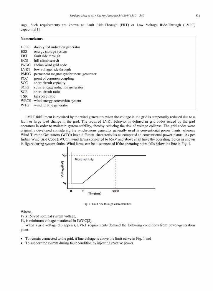
fault or large load change in the grid. The required LVRT behavior is defined in grid codes issued by the grid operators in order to maintain system stability, thereby reducing the risk of voltage collapse. The grid codes were originally developed considering the synchronous generator generally used in conventional power plants, whereas Wind Turbine Generators (WTG) have different characteristics as compared to conventional power plants. As per Indian Wind Grid Code (IWGC), wind farms connected to 66kV and above shall have the operating region as shown in figure during system faults. Wind farms can be disconnected if the operating point falls below the line in Fig. 1.
Fig. 1. Fault ride through characteristics.
Where, Vf is 15% of nominal system voltage, Vpf is minimum voltage mentioned in IWGC[2].
When a grid voltage dip appears, LVRT requirements demand the following conditions from power-generation plant:
To remain connected to the grid, if line voltage is above the limit curve in Fig. 1 and To support the system during fault condition by injecting reactive power.
532 Shrikant Mali et al. / Energy Procedia 54 ( 2014 ) 530 – 540
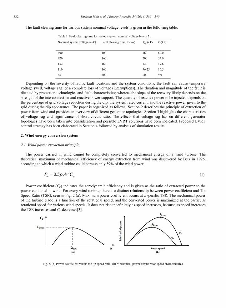
The fault clearing time for various system nominal voltage levels is given in the following table:
Table 1. Fault clearing time for various system nominal voltage levels[2].
Nominal system voltages (kV) Fault clearing time, T (ms) Vpf (kV) Vf (kV)
400 100 360 60.0
220 160 200 33.0
132 160 120 19.8
110 160 96.25 16.5
66 300 60 9.9
Depending on the severity of faults, fault locations and the system conditions, the fault can cause temporary voltage swell, voltage sag, or a complete loss of voltage (interruptions). The duration and magnitude of the fault is dictated by protection technologies and fault characteristics; whereas the slope of the recovery likely depends on the strength of the interconnection and reactive power support. The quantity of reactive power to be injected depends on the percentage of grid voltage reduction during the dip, the system rated current, and the reactive power given to the grid during the dip appearance. The paper is organized as follows: Section 2 describes the principle of extraction of power from wind and provides an overview of different generator topologies. Section 3 highlights the characteristics of voltage sag and significance of short circuit ratio. The effects that voltage sag has on different generator topologies have been taken into consideration and possible LVRT solutions have been indicated. Proposed LVRT control strategy has been elaborated in Section 4 followed by analysis of simulation results.
2. Wind energy conversion system
2.1. Wind power extraction principle
The power carried in wind cannot be completely converted to mechanical energy of a wind turbine. The theoretical maximum of mechanical efficiency of energy extraction from wind was discovered by Betz in 1926, according to which a wind turbine could harness only 59% of the wind power.
30.5m pP Av C (1)
Power coefficient (Cp) indicates the aerodynamic efficiency and is given as the ratio of extracted power to the power contained in wind. For every wind turbine, there is a distinct relationship between power coefficient and Tip Speed Ratio (TSR), seen in Fig. 2 (a). Maximum power coefficient occurs at a specific TSR. The mechanical power of the turbine blade is a function of the rotational speed, and the converted power is maximized at the particular rotational speed for various wind speeds. It does not rise indefinitely as speed increases, because as speed increases the TSR increases and Cp decreases[3].
Fig. 2. (a) Power coefficient versus the tip speed ratio; (b) Mechanical power versus rotor speed characteristics.

Shrikant Mali et al. / Energy Procedia 54 ( 2014 ) 530 – 540 533
2.2. Wind generator topologies
The classification of wind generator topologies is based on overall cost, component count, complexity, control potential, protection, and integration costs[4]. As illustrated in Fig. 3 (a), wind turbine is connected to rotor of Squirrel-Cage Induction Generator (SCIG) through a shaft and gearbox. Since SCIG often runs at constant speed, this topology represents a fixed-speed wind turbine system. Variable speed wind generators are more commonly used owing to higher energy capture and lower mechanical stresses compared with fixed-speed machines. With a variable-speed unit, the generator is connected to the grid using power-electronic converter technology. This allows the turbine speed to be controlled to maximize performance. Fig. 3 (c) shows direct driven Permanent Magnet Synchronous Generator (PMSG) which is capable of variable speed operation; where the generator is connected to the grid using a full converter. The Doubly-Fed Induction Generator (DFIG) is another common variable speed topology which utilizes wound-rotor induction machines with an ac-dc-ac converter between the rotor and grid connections, seen in Fig. 3 (b).
Fig. 3. Wind Generator Topologies (a) SCIG (b) DFIG (c) PMSG.
3. System characteristics
3.1. Characteristics of Voltage Sag
In the context of power quality, a disturbance is a temporary deviation from the steady-state value of voltage caused by faults of short duration, sudden changes in the system or load. It is not possible to eliminate voltage sags even in the most robust and reliable power grids and voltage sag constitute the most significant power quality problem that needs to be tackled. Sag is primarily a short duration rms voltage variation whose magnitude varies between 0.1 pu and 0.9 pu for durations from 0.5 cycles to 1 min.
Fig. 4. Instantaneous voltage sag caused by LG fault

534 Shrikant Mali et al. / Energy Procedia 54 ( 2014 ) 530 – 540
Voltage sag indicates a sudden reduction in voltage at the Point of Common Coupling (PCC) caused by an increase in current. Voltage drop across the network impedance reduces the voltage at PCC. Various sources of voltage sag include:
Faults on high voltage, medium voltage or low voltage lines: Heavy fault current affects bus voltage. All users in the vicinity of the fault are affected, depending upon their proximity to the fault. The duration of faults depend upon operating time of protective devices.
System switching operations: Autoreclosers, switching operation for change-over of lines or transformers cause voltage-dips on the system.
Switching ON of large loads: Induction motors, arc furnaces, welding machines, heaters, boilers, capacitor-bank normally represent short circuit while starting and draw very large starting current, causing voltage dip.
Loose connection may introduce voltage dips intermittently.
Even a quarter second voltage sag can cause the entire machine or process to shut down for hours causing expensive downtime, scrap material, lost productivity and long restart times. Voltage sag leads to slowdown or stopping of induction motors, trips contactors or circuit breakers and leads to failure of inverters. Voltage sag also causes mal-operation or tripping of adjustable speed drives and incorrect operation of control & protective devices.
Solutions for voltage sag include:
Reducing the number of dips by improving the system and minimizing faults. Reducing the duration and depth of dips by improving performance of protective devices and increasing short
circuit power. Increasing immunity of equipment by increasing compliance of equipment and devices.
3.2. Significance of Short Circuit Ratio
To analyze the interaction between wind turbine and grid phenomena, it is important to know the characteristics of the PCC, i.e. the grid point at which the wind power installation is connected to the grid (along with other grid users at that location). PCC is the point where the competences of the grid operator end and the competences of the wind turbine operator begin. The short-circuit power of the grid at the PCC is the apparent power that would flow through a short-circuit at the PCC.
Fig. 5. Hypothetical short-circuit at the PCC to calculate the short-circuit power.
A higher short-circuit power at the PCC implies that varying load or generator currents cause only small voltage disturbances at the PCC, and a grid user has to fear less voltage disturbances caused by other grid users at the same PCC. Short Circuit Ratio (SCR) indicates the strength of grid such that strong grids have SCR of 20 as per German Grid Code and 6 as per IWGC. The speed of recovery tends to degrade as the SCR is decreased and the case of SCR of 2 is an extremely weak system[2]. In equation (2), Sbase is the greater of the demand or the wind installation and the Short Circuit Capacity (SCC) is given by equation (3)[1].
Shrikant Mali et al. / Energy Procedia 54 ( 2014 ) 530 – 540 535
base
SCCSCRS
(2)
2
| |base
base
VSCCZ
(3)
3.3. Effects of voltage sag on various generator topologies
In the case of wind turbines, the effects of voltage sag are different depending on the particular type of wind turbine topology used, as mentioned below:
A. Effects on SCIG:
Generator gets demagnetized and speeds up.
B. Effects on DFIG:
The generator gets demagnetized and speeds up. Converters may fail due to current limitations of the converters.
C. Effects on PMSG:
Generator speeds up. Converters may fail due to current limitations of the converters.
3.4. Solutions for LVRT
Alternative solutions for LVRT technologies have been proposed as follows:
Inserting a chopper resistor into the DC-link so as to dissipate the excessive energy in the form of heat during grid voltage dips. However, the temperature increase in the resistor may be a problem when voltage dip lasts relatively longer[5].
Dumping the energy in an Energy Storage System (ESS), such as super-capacitor, batteries etc. In spite of high cost of ESS, it possesses a number of advantages: it can be accessed at any operating condition, the operation of the machine need not be modified, and it can also enhance LVRT, potentially resulting in transient stability improvements[6].
A certain amount of energy can be stored in rotating masses in the form of inertia; however, this is finite due to the maximum allowable rotor operating speed[7].
By avoiding operation of generator at MPPT during fault condition, the generated power can be reduced and this would help in reducing the size of battery connected at DC-link.
4. LVRT realization and simulation results
A control scheme for implementing LVRT requirements for a 5MW direct driven PMSG based WTG system has been simulated using MATLAB-SIMULINK[8]. Vector Control has been implemented at the generator side and grid side[9,10]. Generator side control aims at controlling the speed of generator wherein the generator is operated at maximum power point with the help of modified Hill Climb Search (HCS) algorithm. Variable step size method has been implemented to obtain the reference rotor speed[11,12]. Under normal conditions, grid side control maintains the DC-link voltage and controls the flow of active and reactive power whereas during fault occurrence, grid side

536 Shrikant Mali et al. / Energy Procedia 54 ( 2014 ) 530 – 540
control targets at reducing the active and reactive power to zero. Chopper resistor connected at DC-link maintains the DC-link voltage constant during grid fault. As per LVRT specifications, active power is not supplied to the grid during fault condition. This excess energy is dissipated in the form of heat through the braking resistor connected at DC-link.
Fig. 6. Block schematic of proposed LVRT scheme.
4.1. Generator and Grid side Control
Field oriented control has been used to implement decoupled control of Permanent Magnet Synchronous Generator. The Field Orientated Control (FOC) consists of controlling the stator current represented by a vector. This control is based upon transforming a three phase quantity into a two phase (d and q) quantity. Field orientated controlled machines need two constants as input references: the torque component (aligned with the q-axis) and the flux component (aligned with the d-axis).
Fig. 7. Field oriented control of generator side converter.
In case of line side vector control, current represented by d-axis is equivalent to active power reference whereas current represented by q-axis is equivalent to reactive power reference.
Fig. 8. Vector control of line side converter.

Shrikant Mali et al. / Energy Procedia 54 ( 2014 ) 530 – 540 537
4.2. Simulation Analysis
The fault may occur in one, two or all the three phases of the AC grid. The results shown below are obtained when an LLLG fault is applied to the system from 1 sec to 1.1 sec. The system has been simulated for the duration of 2 sec based on unity power factor configuration without injecting reactive power. System exhibits transient behavior till 0.25 sec. The overlapping of mechanical and electromagnetic torque for rated wind speed indicates stable operation of the system throughout the simulation[13]. Generator speed remains constant at 1.2 rad/sec for rated wind speed. Voltage level at PCC is 400kV. The maximum fault clearing time specified by IWGC for 400kV grid is 0.1 sec.
Fig. 9. Rated wind speed, generator speed, torque, generator current and generator output power.
Fig. 10. Varying wind speed, generator speed, torque, generator current and generator output power.
The transformer secondary voltage reduces exactly to zero during fault condition, owing to control action of grid side converter. Increase in DC-link voltage for rated wind speed is within acceptable limits. It is important to

538 Shrikant Mali et al. / Energy Procedia 54 ( 2014 ) 530 – 540
maintain the DC-link voltage constant as system may get unstable if the DC-link voltage increases beyond certain limit and it also leads to power electronic converter failure. For varying wind speed, DC-link voltage is held constant at 3194V during fault condition. This is obtained by the switching action of chopper resistor during fault period. The 3 phase nominal rated generator output voltage is 2.2kV rms. The graph of generator voltage indicates that the generator side is not affected by grid fault and produces the expected power precisely.
Fig. 11. Voltage across DC-link for rated wind speed.
Fig. 12. Voltage across DC-link for varying wind speed.
Fig. 13. Generator output voltage.

Shrikant Mali et al. / Energy Procedia 54 ( 2014 ) 530 – 540 539
Fig. 14. Voltage at PCC.
5. Conclusion
Low voltage ride-through plays a significant role in maintaining voltage stability of a grid-connected wind power system. Premature tripping of numerous wind generators due to local disturbances can further risk the stability of the system, contributing to amplification of the effects of the grid disturbances. Variable speed WTG’s equipped with full or partial rating power electronic converters have the ability to extract maximum power from the wind and exhibit strong FRT capability during the grid faults. Simulation results confirm the fulfillment of LVRT requirement, i.e., the generator remains connected to the grid and excess energy is dissipated through chopper resistor in the form of heat during fault occurrence. Generator and grid side control strategies work concurrently to fulfill the LVRT requirements. The main function of the DC-link capacitor is to store energy and to act as a decoupling between the rectifier and the inverter so that each can be controlled separately and isolate the wind turbine systems from the grid which provides protection.
Appendix
Table 2. Simulation parameters.
Parameter Value
Nominal wind speed 12 m/s
Nominal generator power 5 MW
Nominal generator voltage 2.2kV
Nominal generator current 1.3 kA
Nominal DC-link voltage 3200 V
Voltage at PCC 400 kV
References
[1] Wen-Tsan L, Yuan-Kang W, Ching-Yin L, and Chao-Rong C. Effect of low-voltage-ride-through technologies on the first Taiwan offshore wind farm planning. IEEE Trans. Sustain. Energy. 2011; 2(1).
[2] Indian Wind Grid Code Draft. 2009; PP (15-18). [3] Muyeen SM, Takahashi R, Murata T, and Tamura J. A variable speed wind turbine control strategy to meet wind farm grid code requirements.
IEEE Trans. Power Syst. 2010; 25(1). [4] Abbey C, and Joos G. Effect of low voltage ride through (LVRT) characteristic on voltage stability. [5] Li J, Li D, Hong L, Xie C and Chen G. A novel power-flow balance LVRT control strategy for low-speed direct-drive PMSG wind generation
system. IEEE 2010. [6] Abbey C, and Joos G. Supercapacitor energy storage for wind energy applications. IEEE Trans. Ind. Appl. 2007; 43(3). [7] Qureshi WA, and Nair NC-K. Systematic development of low voltage ride through (LVRT) envelope for grids. IEEE 2010.

540 Shrikant Mali et al. / Energy Procedia 54 ( 2014 ) 530 – 540
[8] Sheng-wen L and Guang-qing B. A novel LVRT of permanent magnet direct-driven wind turbine. IEEE 2011. [9] Wang W, Ge B, Bi D, Qin M and Liu W. Energy storage based LVRT and stabilizing power control for direct-drive wind power system.
Int. Conf. on Power Syst. Tech., IEEE 2010. [10] Yang S and Zhang L. Modeling and control of the PMSG wind generation system with a novel controller. 3rd Int. Conf. on Intelligent Syst.
Design and Engg. Appl., IEEE 2013. [11] Alizadeh L, and Yazdani A. A strategy for real power control in a direct-drive PMSG-based wind energy conversion system. IEEE Trans.
Power Del. 2013. [12] Sizhan Z, Jinjun L, Linyuan Z and Yangque Z. Improved DC-link voltage control of PMSG WECS based on feedback linearization under
grid faults. IEEE 2013. [13] Alepuz S, Calle A, Busquets-Monge S, Kouro S and Wu B. Use of stored energy in PMSG rotor inertia for low voltage ride through in back-
to-back NPC converter based wind power systems. IEEE Trans. Ind. Electron. 2012; PP(99).