Embed Size (px)
Citation preview
NUREG/CR4939BNLUNUREG-52031
VOLUME IAN, RV
IMPROVING MOTOR RELIABILITYIN NUCLEAR POWER PLANTS
VOLUME 1: PERFORMANCE EVALUATIONAND MAINTENANCE PRACTICES
M. Subudhi, W.E. Gunther, and J.H. TaylorEngineering Technology DivisionBrookhaven National Laboratory
Upton, New York 11973
A.C. Sugarman and M.W. SheetsNutech Engineers
San Jose, California 95119
Manuscript Completed: June 1987Date Published: November 1987
Prepared for theU.S. NUCLEAR REGULATORY COMMISSION
OFFICE OF NUCLEAR REGULATORY RESEARCHUNDER CONTRACT NO. OE-AC02-76CH00016
FIN A-3270
NOTICE
This report was prepared as an account of work sponsored by an agency of the UnitedStates Government. Neither the United States Government nor any agency thereof, orany of their employees, makes any warranty, expressed or implied, or assumes anylegal liability or responsibility for any third party's use, or the results of such use, ofany information, apparatus, product or process disclosed in this report, or representsthat its use by such third party would not infringe privately owned rights.
The views expressed in this report are not necessarily those of the U.S. NuclearRegulatory Commission.
Available fromSuperintendent of Documents
U.S. Government Printing OfficeP.O. Box 37082
Washington, DC 20013-7982and
National Technical Information ServiceSpringfield, Virginia 22161
-iii-
ABSTRACT
This report constitutes the first of the three volumes under this NUREG. Thereport presents recommendations for developing a cost-effective program forperformance evaluation and maintenance of electric motors in nuclear powerplants. These recommendations are based on current industry practices, availabletechniques for monitoring degradation in motor components, manufacturer'srecommendations, operating experience, and results from two laboratory tests onaged motors. Two laboratory test reports on a small and a large motor arepresented in separate volumes of this NUREG. These provide the basis for thevarious functional indicators recommended for maintenance programs in thisreport.
The overall preventive maintenance program is separated into two broad areas ofactivity aimed at mitigating the potential effects of equipment aging:Performance Evaluation and Equipment Maintenance. The latter involves actuallymaintaining the condition of the equipment while the former involves thoseactivities undertaken to monitor degradation due to aging. These monitoringmethods are further categorized into periodic testing, surveillance testing,continuous monitoring and inspections.
This study focuses on the methods and procedures for performing the aboveactivities to maintain the motors operationally ready in a nuclear facility.This includes an assessment of various functional indicators to determine theirsuitability for trending to monitor motor component condition. The intrusive-ness of test methods and the present state-of-the-art for using the test equip-ment in a plant environment are discussed.
In conclusion, implementation of the information provided in this report, willimprove motor reliability in nuclear power plants. The study indicates the kindsof tests to conduct, how and when to conduct them, and to which motors the testsshould be applied. It should be noted that the recommendations and conclusionsprovided in this report are based on research findings, and as such should not beconstrued as regulatory or statutory requirements for motors in nuclear powerplants.
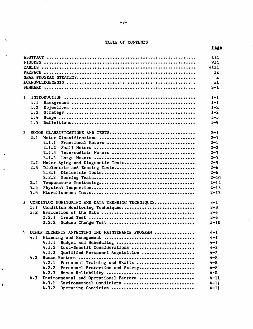
TABLE OF CONTENTSPage
ABSTRACT ........ ........................................ iiiFIGURES ............................................................ viiTABLES ..................................... viiiPREFACE ..................................... ixNPAR PROGRAM STRATEGY ........................ *.......... xACKNOWLEDGEMENTS .............................................. xiSUMMAiRY ..................................... .... S-1
1 INTRODUCTION ................. 1-11.1 Background ................................................. 1-11.2 Objectives ................................. ........... * 1-21.3 Strategy ..................................... 1-21.4 Scope ...................................................... 1-51.5 Definitions..... ..................................................... 1-9
2 MOTOR CLASSIFICATIONS AND TESTS .................................. 2-12.1 Motor Classifications .................... .................. 2-1
2.1.3 Intermediate Motors ................................. 2-32.1.4 Large Motors ... ..................................... 2-5
2.2 Motor Aging and Diagnostic Tests............................ 2-52.3 Dielectric and Bearing Tests. . ............................... 2-6
2.3.1 Dielectric Tests.......................................... 2-62.3.2 Bearing Tests.........00.0*0000* ... .*0......0.... . .. 2-10
2.4 Temperature Monitoring..... * * * * * .... .......... . 2-122.5 Physical Inspection.. .. o.o........ ......... o o.............. 2-132.6 Miscellaneous Testso....o.o.... o.o.e... .................... 2-13
3 CONDITION MONITORING AND DATA TRENDING TECHNIQUES................ 3-13.1 Condition Monitoring Techniques.........o .. .. .. o........ee 3-33.2 Evaluation of the Data ..................................... 3-6
3.2.1 Trend Test ......... 0. ................................ 3-63.2.2 Sudden Change Test ........ . . . . . . . . . . . . . ............. 3-10
4 OTHER ELEMENTS AFFECTING THE MAINTENANCE PROGRAM ................ 4-14.1 Planning and Management .................................... 4-1
4.1.1 Budget and Scheduling ............................ . 4-14.1.2 Cost-Benefit Considerations ......................... 4-24.1.3 Qualified Personnel Acquisition ............*.....*.. 4-7
4.2 Human Factors ....... *.. ... ................... ...... ..... .. 4-84.2.1 Personnel Training and Skills ... .................... 4-84.2.2 Personnel Protection and Safety....................... 4-84.2.3 Human Reliability ...... .............................. 4-8
4.3 Environmental and Operational Factors ...................... 4-114.3.1 Environmental Conditions ............................ 4-114.3.2 Operating Condition ........ * . . . . . . . . . . . . . ......... 4-11
-vi-
TABLE OF CONTENTS (Cont'd) Page
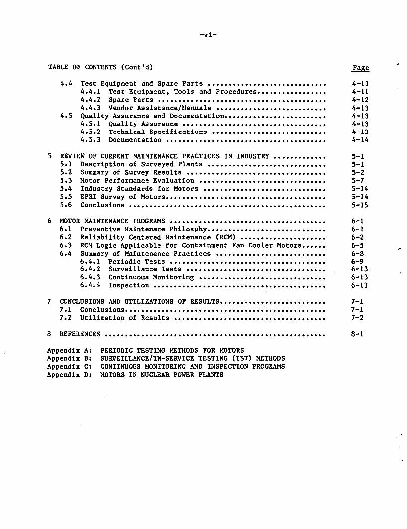
4.4 Test Equipment and Spare Parts ............................. 4-114.4.1 Test Equipment, Tools and Procedures................. 4-114.4.2 Spare Parts ........................................ 4-124.4.3 Vendor Assistance/Manuals ........................... 4-13
4.5 Quality Assurance and Documentation.......................... 4-134.5.1 Quality Assurance *.................................. 4-134.5.2 Technical Specifications ............................ 4-134.5.3 Documentation ....................................... 4-14
5 REVIEW OF CURRENT MAINTENANCE PRACTICES IN INDUSTRY ............. 5-15.1 Description of Surveyed Plants ............................. 5-15.2 Summary of Survey Results .o.o......... ........................ 5-25.3 Motor Performance Evaluation ............................... 5-75.4 Industry Standards for Motors .............................. 5-145.5 EPRI Survey of Motors....................................... 5-145.6 Conclusions ................................................ 5-15
6 MOTOR MAINTENANCE PROGRAMS .............. ........................ 6-16.1 Preventive Maintenace ...................................... 6-16.2 Reliability Centered Maintenance (RCM) .... ................. 6-26.3 RCM Logic Applicable for Containment Fan Cooler Motors...... 6-56.4 Summary of Maintenance Practices ........................... 6-8
6.4.1 Periodic Tests ............ ........................... 6-96.4.2 Surveillance Tests .............................. 6-136.4.3 Continuous Monitoring ............................... 6-136.4.4 Inspection ........................................ 6-13
7 CONCLUSIONS AND UTILIZATIONS OF RESULTS .......................... 7-17.1 Conclusions .. Oo.oofo.oo.o*0000000000....... .............................. 7-17.2 Utilization of Results ....... ........ ............. 7-2
8 REFERENCES ...... o........................................ 8-1
Appendix A: PERIODIC TESTING METHODS FOR MOTORSAppendix B: SURVEILLANCE/IN-SERVICE TESTING (IST) METHODSAppendix C: CONTINUOUS MONITORING AND INSPECTION PROGRAMSAppendix D: MOTORS IN NUCLEAR POWER PLANTS
-vii-
FIGURES
Page
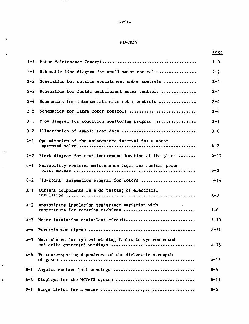
1-1 Motor Maintenance Concept...................................... 1-3
2-1 Schematic line diagram for small motor controls ............... 2-2
2-2 Schematics for outside containment motor controls ............. 2-4
2-3 Schematics for inside containment motor controls .............. 2-4
2-4 Schematics for intermediate size motor controls .... ........... 2-4
2-5 Schematics for large motor controls ........................... 2-4
3-1 Flow diagram for condition monitoring program ................. 3-1
3-2 Illustration of sample test data .............................. 3-6
4-1 Optimization of the maintenance interval for a motoroperated valve ......... ................. *** ***.. 4-7
4-2 Block diagram for test instrument location at the plant ....... 4-12
6-1 Reliability centered maintenance logic for nuclear powerplant motors ..... ............................................ 6-3
6-2 '10-point' inspection program for motors ...................... 6-14
A-1 Current components in a dc testing of electricalinsulation .... * .......... ........ ** ............... A-3
A-2 Approximate insulation resistance variation withtemperature for rotating machines ............................. A-6
A-3 Motor insulation equivalent circuit............................. . A-10
A-4 Power-factor tip-up ...... .......................... * ........ A-11
A-5 Wave shapes for typical winding faults in wye connectedand delta connected windings .................................. A-13
A-6 Pressure-spacing dependence of the dielectric strengthof gases ............................................. *........ A-15
B-1 Angular contact ball bearings ................................. B-4
B-2 Displays for the MOVATS system ...... ............................ B-12
D-1 Surge limits for a motor ..... D-5........... ...... *..........
-viii-
TABLES
Page
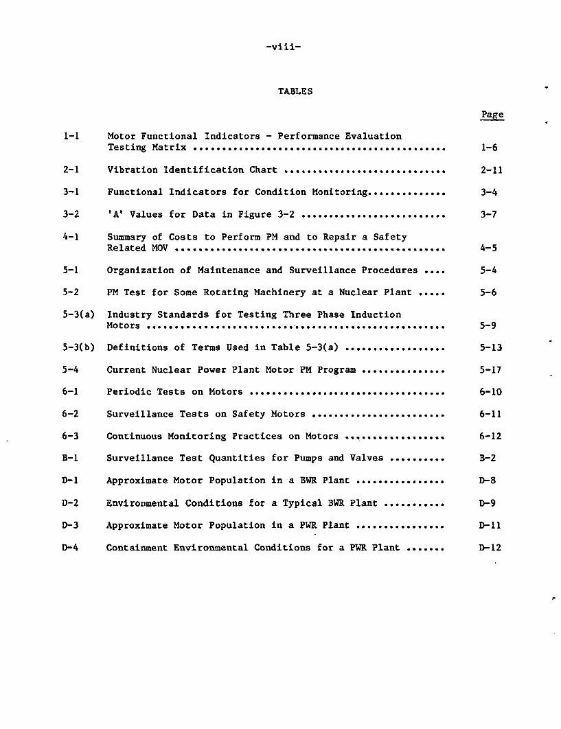
1-1 Motor Functional Indicators - Performance EvaluationTesting Matrix ........ ..................................... 1-6
2-1 Vibration Identification Chart ............................. 2-11
3-1 Functional Indicators for Condition Monitoring.............. 3-4
3-2 'Al Values for Data in Figure 3-2 .......... 0................ 3-7
4-1 Summary of Costs to Perform PM and to Repair a SafetyRelated MOV ................................ 4-5
5-1 Organization of Maintenance and Surveillance Procedures ..0* 5-4
5-2 PM Test for Some Rotating Machinery at a Nuclear Plant ..... 5-6
5-3(a) Industry Standards for Testing Three Phase InductionMotors ................................ 5-9
5-3(b) Definitions of Terms Used in Table 5-3(a) .................0. 5-13
5-4 Current Nuclear Power Plant Motor PM Program ............... 5-17
6-1 Periodic Tests on Motors *.................................. 6-10
6-2 Surveillance Tests on Safety Motors ........................ 6-11
6-3 Continuous Monitoring Practices on Motors .................. 6-12
B-1 Surveillance Test Quantities for Pumps and Valves .......... B-2
D-1 Approximate Motor Population in a BWR Plant ................ D-8
D-2 Environmental Conditions for a Typical BWR Plant ........... D-9
D-3 Approximate Motor Population in a PWR Plant ................ D-11
D-4 Containment Environmental Conditions for a PWR Plant ....... D-12
-ix-
PREFACE
For all practical purposes this NUREG, comprising three volumes, completes theNuclear Plant Aging Research (NPAR) program study of electric motors in nuclearapplications. The results of the Phase I study were issued in June 1985 asNUREG/CR-4156. This NUREG addresses the results of the Phase II work. Volume 1of this NUREG describes various motor test methods and includes recommendationsfor their use. Volume 2 describes the results of a small motor test performed toevaluate functional indicators, and volume 3 contains an analysis and a diagnos-tic test on the stator windings of a large motor.
Recommendations provided in this report are based on the large body of work com-pleted in Phase I, consultations with experts in the field, and the two series ofmotor tests conducted in Phase II. The authors feel the results are sound andworthy of implementation. Conclusive verification of these recommendations canonly be achieved by in situ application. Therefore, it is hoped that the nuclearindustry will develop pilot programs implementing the recommendations embodied inthis work.
This is the first complete aging assessment conducted under the NRC NPAR program,and the authors feel it demonstrates the usefulness of this important researchprogram.
J. TaylorBNL Program Manager
(The NPAR program strategy as defined in the NRC program plan, NUREG-1144, isattached for the readers information.)
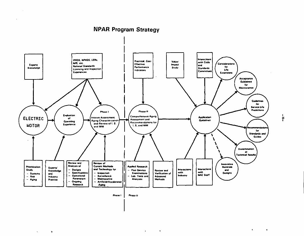
NPAR Program Strategy
I
-xi-
ACKNOWLEDGEMENTS
The authors wish to thank Drs. Satish Aggarwal and Jit Vora of the U.S. NuclearRegulatory Commission for their assistance and useful comments on various phasesof this work. We would like to express our appreciation to Mr. Richard Bucci ofEbasco Services for providing valuable information on motors in nuclear powerplants.
We would like to express our gratitude to various members of the EngineeringTechnology and Reactor Divisions of BNL who contributed towards the completion ofthis work. In particular, we wish to thank Mr. Robert Hall, Mr. James Higgins,Mr. William Shier, Dr. John O'Brien and Mr. Otto Jacobi who provided technicalassistance, guidance, and editing of the report.
We thank Hr. J. E. Thomas of EPRI Equipment Qualification Advisory Group (EQAG),Mr. Philip M. Holzman of Strategic Technology and Resources Inc., Mr. GeorgeSliter of EPRI, and the utility respondents for their input on the Motor Mainte-nance/Surveillance Survey (MM/SS) conducted in June 1987.
The assistance of the Word Processing Center in typing this manuscript is alsodeeply appreciated.
S-1
SUMMARY
The objectives of this Phase II NPAR motor study are 1) the assessment of inspec-tion, surveillance, maintenance, and condition monitoring methods and 2) thedevelopment of criteria which can be used for the formulation of a cost effectivemaintenance program. The Phase I study (NUREG/CR-4156) identified the typicalmotor failures and various functional indicators to monitor age-related degrada-tion.
In order to make decisions related to motor maintenance, the sizes, types, andnumber of motors in nuclear power plants were assessed. Critical applications ofmotors for plant safety and availability were also identified. The contemporaryBWR/PWR contains approximately 1100 motors, with the largest applications beingfor AC motor-operated valves and continuous duty motors in the 1-100 hp range.
Periodic testing, surveillance techniques and continuous monitoring methods werereviewed and assessed. Methods are presented herein for performance evaluationand trend analysis, as well as for a value impact analysis.
Current industry maintenance practices were assessed by reviewing the motor main-tenance requirements at four nuclear power stations. Insulation resistance isalways measured, whereas motor running current is recorded only in some cases.Most testing is done for the driven equipment, such as MOV stroke time or pumpspeed, which gives little indication of motor condition. With exception to largemotor bearings, trend analysis is not that extensive for insulation condition.
A discussion of reliability centered maintenance (RCM) is presented, along with alogic chart to make motor maintenance decisions using RCM philosophy. This logicis applied to the specific application of containment fan cooler motors. Theresultant maintenance recommendations do not necessitate any hard ware modifica-tions, but do require more testing and trend analysis than is currently performedat most nuclear power plants.
A 10 hp industrial motor with 12 years of service life in a commercial nuclearplant and a 400 hp failed motor with more than 24 years of service life in anuclear research reactor facility were tested. The 10 hp motor was subjected toplug reversal cycling to induce age-related degradation while monitoring variousfunctional indicators. The 400 hp motor stator was tested to diagnose age-relat-ed deterioration of insulation dielectric properties. The test objectives wereto identify the functional indicators which were cost-effective and provide ade-quate feedback indicating whether or not degradation was occurring. These testresults are discussed in separate volumes of this NUREG Report.
In conclusion, a strategy has been developed for establishing a motor maintenanceprogram. Tests, monitoring and inspection activities are recommended to detectas well as monitor degradation in motors due to aging and service wear. Thesetechniques are intended to identify any local defects or the average condition ofdielectric and rotational integrities of motors at an incipient stage. Technical
S-2
information is provided on the kinds of tests to conduct, how and when to conductthem, and for what sizes of motors these tests are applicable.
The information presented in this report can be applied directly by utilities toestablish an effective motor maintenance program. By following the logic diagrampresented in section 6.2, the type of maintenance program best suited for a par-ticular motor or group of motors can be determined. The method used is based onreliability centered maintenance and will result in a maintenance program tailor-ed to meet the specific needs of the plants. Once the type of program requiredhas been determined, the information presented in section 6.4 can be used toobtain details on the specific tests and inspections that should be performed.This is based on motor size and application. Other factors which must be con-sidered, such as data trending and administrative concerns, are discussed in sec-tions 3 and 4, respectively. Supplemental information on performance of the var-ious tests can be obtained from the Appendices.
1-1
1 INTRODUCTION
1.1 Background
Motor degradation due to aging and service wear significantly increases thepotential for a catastrophic failure, particularly during a power plant accidentand post-accident conditions. The impact of motor failures on plant safety is animportant concern among the nuclear utilities and the government agency regulat-ing this industry. Economic impacts, relating to plant availability and safety,as well as corrective maintenance, have prompted utilities to improve their main-tenance programs to mitigate such aging effects.
Current motor maintenance activities in the utility industry do not seemextensive specifically in the areas of detecting and monitoring age-relateddegradation. However, with the high costs of plant down-time, coupled with thesafety impact of a motor failure, the utilities and the regulating agency havefocused their resources on achieving better maintenance and surveillanceprograms, thus improving plant reliability and safety. This effort includesestablishing computer data bases, as well as evaluating motor conditions and thetrend of motor performance data. The, use of increasingly sophisticatedtechniques to identify motor defects at an incipient stage is being initiated bysome utilities.
Despite the fact that modern motors are better and more sophisticated than oldermotors, and maintenance practices are more extensive, they still fail. Mostmotor failures described in the operating experience data bases had occurred dur-ing starting. The insulating system and bearing assemblies were the dominantfailure modes, accounting for almost seventy percent of the reported failures.Monitoring the state of these two sub-components, using cost-effective techni-ques, could eliminate many untimely failures and thus improve the overall systemreliability and plant availability.
Studies sponsored by industry (1-2) on motors have been conducted by the ElectricPower Research Institute (EPRI) to identify failure modes, to extend motor lifeexpectancy, and to develop a cost-effective preventive maintenance program.Other studies (3-6) have emphasized similar objectives and have developed similarrecommendations to improve motor reliability. The electric utility industry,although recognizing the need and the benefit of a good motor maintenance pro-gram, has not implemented a uniform maintenance strategy. Many of the smallersafety-related motors are given minimal attention unless mandated by the plantmaintenance programs. This is in contrast to the extensive maintenance conductedon many non-safety related large motors. This- is due to the large differences inreplacement or repair costs and also to their role in supporting electrical gen-eration. In some instances, unnecessary prescriptive maintenance is done on com-ponents without analyzing or trending the test data to determine if it is war-ranted.
Numerous standards and guides are available for testing, maintaining and monitor-ing motor components. Electrical tests on the insulating system and mechanicaltests on the bearing assemblies are described frequently. Studies (1-6) havesuccessfully identified the predominant failure modes and the proceduresnecessaryfor restoring the equipment to a running condition. Standards published by theInstitute of Electrical and Electronics Engineers (IEEE) (see Section 5.4) alsodescribe monitoring techniques to diagnose the root cause of failure.
1-2
1.2 Objectives
The Phase I motor study (7) has identified the typical failures and various func-tional indicators to monitor age-related degradation. The objectives of thesecond phase studies under the Nuclear Plant Aging Research (NPAR) program are:
* to assess methods of inspection, surveillance, maintenance, and conditionmonitoring, or of evaluating residual life of motors, which will assuretimely detection of significant aging and service wear effects from theabnormal indication of functional parameters (identified in the NPAR firstphase study), prior to loss of safety function, and
* to formulate a cost-effective preventive maintenance program to be imple-mented for storage, maintenance, repair, and refurbishment of motors in mi-tigating the effects and in diminishing the rate and extent of degradationcaused by aging and service wear.
This study is intended to help NRC resolve safety issues as well as to as surethe operational readiness of safety motors during normal and accident conditions.Also, it will help industry develop their own cost-effective maintenance program.Improving motor reliability will increase the component availability and hence,the plant safety. Other benefits of this study may include providing input toreviews of plant life extension, plant relicensing, and the lay-up and storage ofequipment. Finally, improvements can be achieved in current codes, standards andguides to incorporate aging and service wear effects.
1.3 Strategy
By definition Maintenance is the "....action of maintaining or the state of beingmaintained..." and may include replacements, adjustments, repairs, overhauls andinspection of components or equipment. According to the NRC Maintenance and Sur-veillance Program Plan (NUREG-1212, Volume 1), Maintenance is defined as a pro-cess with the objective of preserving the reliability and safety of nuclear powerplant structures, systems, and components or restoring that reliability when itis degraded. Preventive maintenance is that action which helps prevent equipmentfrom failing prematurely. Recently, several studies (8-10) used maintenance-related terminology, such as surveillance, trending, condition monitoring, andtesting as a part of their dialogue. This has created some confusion amongresearchers. The following discussion is intended to define this terminology,which will also help in understanding this report.
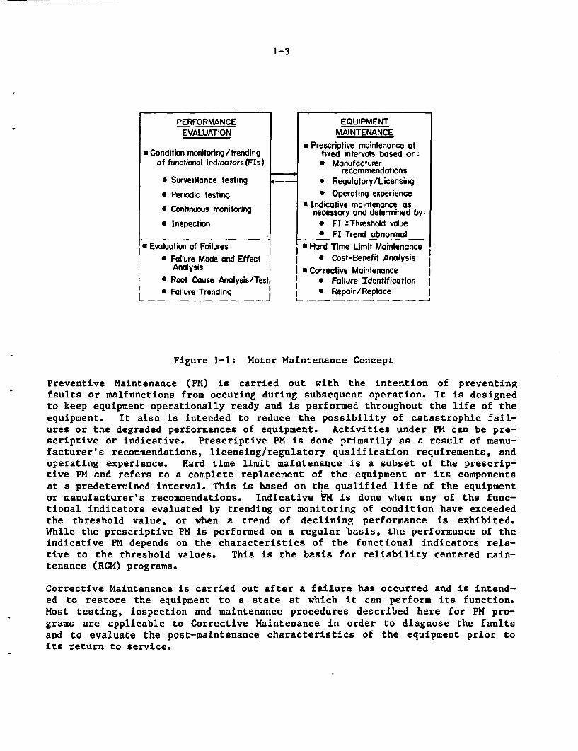
Maintenance, preventive or corrective, applicable to a component is defined as anactivity or activities intended to keep the equipment in satisfactory conditionor to restore it to a state at which it can perform its design function. Thisinvolves inspections, replacements, adjustments, overhauls, and repairs of thesub-components. Performance evaluation of a component is an essential counter-part of maintenance, as shown in Figure 1-1, and is defined as the qualitative orquantitative assessment of the equipment operational readiness by performingtests and/or inspections to monitor the "health" of the equipment. These activi-ties are generally carried out by the maintenance group in a plant.
1-3
PERFORMANCE EQUIPMENTEVAWATION MAINTENANCE
* Prescriptive maintenance at* Condition monitoring/trending fixed intervals based on:
of functional indicators(FIs) * Manufacturer-recommendations
* Surveillance testing * Regulatory/Licensing
* Periodic testing * Operating experience* Indicative maintenance as* Continuous monitoring necessary and determined by:
* Inspection 0 Fl kThreshold vdue* Fl Trend abnormal
* Evaluation of Failures * Hard lime Limit Maintenance* Failure Mode and Effect * Cost-Benefit Analysis
Analysis I I *Corrective Maintenance lI * Root Couse Analysis/Testl | 0 Failure Identification
L Falure Trending I * Repair/Replace l
Figure 1-1: Motor Maintenance Concept
Preventive Maintenance (PM) is carried out with the intention of preventingfaults or malfunctions from occuring during subsequent operation. It is designedto keep equipment operationally ready and is performed throughout the life of theequipment. It also is intended to reduce the possibility of catastrophic fail-ures or the degraded performances of equipment. Activities under PM can be pre-scriptive or indicative. Prescriptive PM is done primarily as a result of manu-facturer's recommendations, licensing/regulatory qualification requirements, andoperating experience. Hard time limit maintenance is a subset of the prescrip-tive PM and refers to a complete replacement of the equipment or its componentsat a predetermined interval. This is based on the qualified life of the equipmentor manufacturer's recommendations. Indicative PM is done when any of the func-tional indicators evaluated by trending or monitoring of condition have exceededthe threshold value, or when a trend of declining performance is exhibited.While the prescriptive PM is performed on a regular basis, the performance of theindicative PM depends on the characteristics of the functional indicators rela-tive to the threshold values. This is the basis for reliability centered main-tenance (RCM) programs.
Corrective Maintenance is carried out after a failure has occurred and is intend-ed to restore the equipment to a state at which it can perform its function.Most testing, inspection and maintenance procedures described here for PM pro-grams are applicable to Corrective Maintenance in order to diagnose the faultsand to evaluate the post-maintenance characteristics of the equipment prior toits return to service.
1-4
The need for indicative maintenance is based on a qualitative or quantitativeassessment of equipment functional indicators. This evaluation includes electri-cal, mechanical, or chemical tests to obtain quantitative values for the currentfunctional indicators (FIs). It also includes continuous monitoring of certainFIs, as well as routine equipment inspection. A clear understanding of the var-ious elements of performance evaluation is necessary as they pertain to currentindustrial practices.
In this study, the overall preventive maintenance (PM) program was thus separatedinto two broad areas of activity aimed at mitigating the potential effects ofequipment aging: (1) Performance Evaluation, and (2) Equipment Maintenance.Equipment maintenance involves actually maintaining the condition of the equip-ment while performance evaluation involves only those activities undertaken tomonitor signs of degradation due to aging. The equipment maintenance could beprescriptive and/or indicative. Performance evaluation activities include eval-uation of the functional indicators obtained from (1) Surveillance Testing, (2)Periodic Testing, (3) Continuous Monitoring, and (4) Inspection, and are used asa basis for indicative PM. Also included in these activities are failure modesand effect analysis (FMEA), root cause analysis, tests on failed motor compo-nents, and trends associated with these failures.
The dictionary definition of surveillance testing is close observation of thecondition of equipment to detect degradation that may lead to failure caused byaging and other environmental stresses (such as dust, humidity, vibration, andseismic motion). It is widely accepted in the nuclear industry that surveillancealso means those mandatory tests required by the plant technical specifications(tech spec) and ASHE section XI (11-12) for in-service testing (IST) of pumps andvalves. This study refers to surveillance test as those tests required by planttech spec commitments.
Periodic tests include in situ tests performed in the plant at scheduled inter-vals to detect failures and verify motor operation. The parameters, measured bytest equipment, provide indication of age or deterioration related to servicewear. Periodic tests are similar in type to surveillance tests, but are notrequired by tech specs. These tests typically are recommended by the manufac-turers and are described in industry standards. Continuous monitoring, by defi-nition, is the monitoring of certain functional indicators continuously and,requires data recording devices that are permanently installed (such as ammetersand voltmeters). Information from these devices is also important for checks ofpost-maintenance operability. Equipment inspection is defined as those activi-ties which do not require test equipment or tools, and these include listening tothe noise level, examining the surface for deterioration and applying hand forcesto assess the mounting or structural integrity.
The motor functional indicators evaluated in this study for each of the four cat-egories are summarized in Table 1-1. By definition, some of these parameterscan be included in more than one category. For example, the motor running cur-rent, which may be easily measured by using a clamp-on ammeter (if it is not con-tinuously monitored), can be part of the surveillance testing or the continuousmonitoring program (i.e. on-line monitoring). Similarly, the motor or bearingvibration can be part of any of the four categories. If the testing is donewith portable vibration units, then it becomes periodic testing. If it is includ-ed in the plant tech specs, then it can be considered as surveillance testing.
1-5
Large motors often have permanent instruments for vibration measurement andtherefore can be monitored continuously or as part of the on-line monitoring sys-tem. If vibration is examined simply by touching with the hand or observing someabnormal motions without using any portable or sophisticated equipment, then thisactivity becomes part of the inspection program.
Therefore, the categorization of any motor functional indicator is dependent uponthe type of measuring to which it is subjected. In this report, the motor runn-ing current is discussed under periodic testing. Vibration is reviewed in thesurveillance testing section, since for pumps this parameter is sometimes includ-ed in the plant tech spec requirements as part of the ASME in-service inspectionprogram.
The data gathered from tests and inspection activities can be generalized by theterm performance evaluation. To quantify the performance of the equipment so asto predict its current and future state, trending of this data is essential.
The functional indicators identified in the phase I study (7), are monitored and/or trended by activities undertaken as part of the performance evaluation task ofthe motor maintenance program. Table 1-1 illustrates the correlation among themotor dielectric, rotational and mechanical integrities and testing, monitoring,and inspecting activities.
1.4 Scope
The phase 1 motor study (7) included a description of motor designs and construc-tion materials. Failure modes, causes, and mechanisms were determined by review-ing the environmental and operational conditions experienced by motors in nuclearpower plants, augmented by the last decade of operating experiences in nuclearapplications. The study also included a preliminary review of design and speci-fications, along with standards and guides. To determine the motor dielectric,rotational, and mechanical integrities, the functional indicators were identi-fied. When properly monitored, these parameters indicate component deteriorationdue to aging.
The second phase study, with the specific objectives mentioned earlier, includesall the salient points to develop a cost-effective preventive maintenance pro-gram. Although no program can provide absolute assurance that failures will beeliminated, proper implementation of the procedures recommended in this reportcan improve motor reliability which, in turn, will improve plant safety andavailability.
A nuclear power plant contains motors of various sizes and types, locatedthroughout the facility. As a result, it is difficult to generalize motor cha-racteristics for all plant environments and applications. Therefore, a study wasmade to identify the size, type, and specifications of motors used in safetyapplications in a typical Pressurized Water Reactor (PWR) and in the Mark I, II,and III Boiling Water Reactor (BWR) designs. A reasonable estimate of the plantmaintenance effort could be achieved for implementing the recommended practicesfor a particular class of motors.
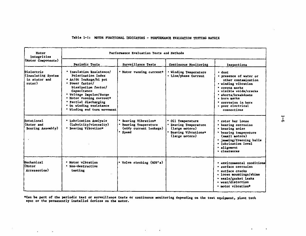
Table 1-1: MOTOR FUNCTIONAL INDICATORS - PERFORMANCE EVALUATION TESTING MATRIX
Motor Performance Evaluation Tests and MethodsIntegrities
(Motor Components)Periodic Tests Surveillance Tests Continuous Monitoring Inspections
ielectric * Insulation Resistance/ * Motor running current* o Winding Temperature dust
(Insulating System Polarization Index * Line/phase Current * presence of water or
in stator and Ac/dc leakage/hi pot other contamination
rotor) * Power factor/ winding vibration
Dissipation factor/ * corona marksCapacitance visible voids/cracks
* Voltage Impulse/Surge * shorts/breakdowns* Motor running current* burn marks
* Partial discharging * corrosion in bars* De winding resistance poor electrical* Winding end turn movement connections
Rotational * Lubrication Analysis * Bearing Vibration* * Oil Temperature rotor bar loose
(Rotor and (Lubricity/viscosity) * Bearing Temperature * Bearing Temperature bearing corrosionBearing Assembly) *Bearing Vibration* (eddy current leakage) (large motors) * bearing noise
Speed * Bearing Vibrations* bearing temperature(large motors) (small motors)
* jamming/freezing balls* lubrication level* alignmentv clearances
echanical * Motor vibration * Valve stroking (MOV's) * environmental conditions
(Motor Non-destructive * surface corrosion
Accessories) testing * surface cracks* loose mountings/shims* seals/gasket leaks* wear/distortion* motor vibration*
*Can be part of the periodic test or surveillance tests or continuous monitoring depending on the teat equipment, plant tech
spec or the permanently installed devices on the motor.
a'
1-7
Regardless of application and size, motors have similar components; stator,rotor, bearings, and accessories, as identified in the phase 1 study (7).Because of their construction and material characteristics, motors require cer-tain maintenance activities and tests no matter where they are located. However, safety considerations, economics, environmental parameters, and motorapplications may dictate the type and frequency of maintenance work activities.For example, performing sophisticated tests on a fractional horsepower motor usedfor strip-chart recording in the control room is not a wise decision since thismotor could be replaced every year at minimum cost with no impact on safety. Onthe other hand, for 5,000 hp safety related motors equipped with sophisticatedmonitoring features, good maintenance practices are mandated for both safety andeconomic reasons.
Nuclear motors have similar histories of failure as those with non-nuclear appli-cations. Insulating systems (dielectric integrity) and bearings (rotationalintegrity) are responsible for most motor failures. As a result, most industrystandards and guides are written on testing and maintenance of these components.Very little maintenance guidance is available for other motor components.
A summary was made of the tests used by the nuclear industry in plant maintenanceand surveillance programs. Each test procedure is described to provide the basicprinciples of measurement followed by these discussions:
present industry practicesindustry standards/guidesrequired test equipmentmajor sources of measurement errorsrecommendations with test frequency (if possible) and safety limits.
Insulation test recommendations are taken from publications by the Institute ofElectrical and Electronics Engineers (IEEE) and National Electrical ManufacturersAssociation (NEMA) while bearing tests are obtained from the American Society ofMechanical Engineers (ASME) and Anti-Friction Bearing Manufacturers Association(AFBMA). Other recommended standards also are considered in the study. Mainte-nance tests are listed separately from the surveillance procedures currentlyadopted by the power industry.
A survey of the maintenance and surveillance programs for continuous duty as wellas intermittent (valve operator) motors was conducted at four nuclear facilities.The plants included two PWR and two BWR facilities with several years of operat-ing experiences. The survey included a review of selected maintenance and sur-veillance procedures and computerized Preventive Maintenance (PM) programs. Thecomparison of different procedures provided the following types of information:
tests performed and the procedures needed in processing the test dataacceptance criteriadata recordedprocedure formats.
1-8
The purpose of this evaluation is to familiarize the reader with the currentpractices adopted in nuclear industry and to study procedural developments.
Performance evaluation of the equipment is also a part of the maintenance andsurveillance activities and is a quantitative, predictive technique for assessingthe "health" of the equipment. Trending the maintenance testing data is animportant aspect of the condition monitoring (CM) program. In recent years,utilities have given special consideration to condition monitoring of certainmotors which are either very expensive or vital to plant safety. However, anunpublished EPRI study indicated that CM on motors using insulation resistanceand polarization index tests provided no trending data that was useful in des-cribing the motor condition. This study was based on motors that were artifi-cially aged in a mild environment without humidity. The components were aged toan equivalent life of 50 years. With this type of aging, the motors may not haveexperienced any insulation damage because of the lack of heat and humiditycycles, which is a key factor for insulation degradation. Therefore, monitoringa motor for its condition remains an uncharted topic of significant importance.
A scheme is presented for performing cost-benefit analysis. Recommendations fortesting are based on the motor size and its importance to plant safety. Otherelements governing a good maintenance program also are discussed.
Thus, the scope of this phase of the motor study includes basic elements fordeveloping a good maintenance program for motors in nuclear power plants. How-ever, with the present knowledge, the suitability of using any particular insula-tion test for a motor is difficult to assess. Test programs were conducted todefine the applicability of the functional indicators for condition monitoring aspart of the motor PM program. The test results are presented in separate volumesof this NUREG report. It is concluded that certain functional parameters changeas the components degrade with age. Therefore, by trending these parameters, themotor can be maintained in an operationally ready condition.
Motor classification and various functional indicators are discussed in Section2. Condition monitoring methods and functional indicator trending obtained fromthe plant maintenance and surveillance program are given in detail in Section 3.Section 4 describes the other elements relating to motor maintenance, thatinclude planning, management, human factors, environmental and operational fac-tors, test equipment, spare parts, and quality assurance. Section 5 includessurvey results which indicate the present industry practices used to keep motorsoperating for the life of the plant. Section 6 describes procedures to selectmaintenance types for nuclear plant motors and Section 7 gives the conclusions ofthis phase 2 study. The basic principles of all the tests utilized in mainte-nance and surveillance applications are discussed in Appendices A and B,respectively. Appendix C outlines some of the continuous monitoring and inspec-tion procedures applicable to motor performance evaluation. Appendix D discussesmotor design and specifications for protecting components from abnormal condi-tions and their application to nuclear power plants.
1-9
1.5 Definitions
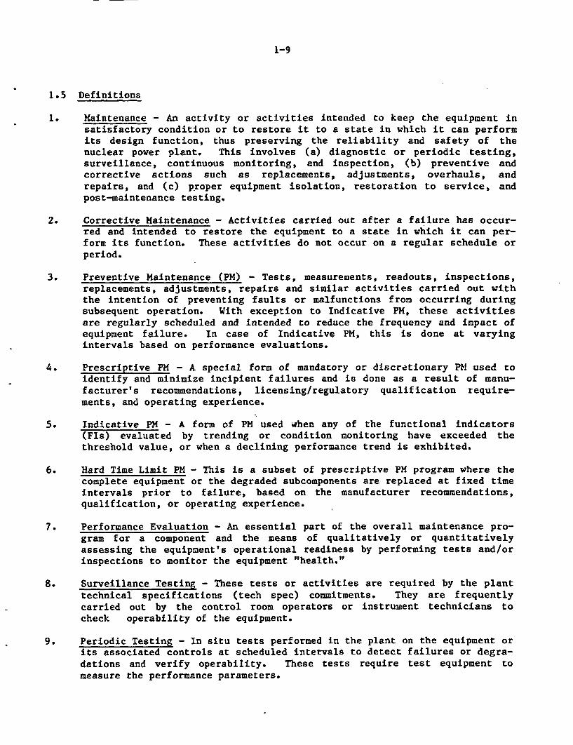
1. Maintenance - An activity or activities intended to keep the equipment insatisfactory condition or to restore it to a state in which it can performits design function, thus preserving the reliability and safety of thenuclear power plant. This involves (a) diagnostic or periodic testing,surveillance, continuous monitoring, and inspection, (b) preventive andcorrective actions such as replacements, adjustments, overhauls, andrepairs, and (c) proper equipment isolation, restoration to service, andpost-maintenance testing.
2. Corrective Maintenance - Activities carried out after a failure has occur-red and intended to restore the equipment to a state in which it can per-form its function. These activities do not occur on a regular schedule orperiod.
3. Preventive Maintenance (PM) - Tests, measurements, readouts, inspections,replacements, adjustments, repairs and similar activities carried out withthe intention of preventing faults or malfunctions from occurring duringsubsequent operation. With exception to Indicative PM, these activitiesare regularly scheduled and intended to reduce the frequency and impact ofequipment failure. In case of Indicative PM, this is done at varyingintervals based on performance evaluations.
4. Prescriptive PM - A special form of mandatory or discretionary PM used toidentify and minimize incipient failures and is done as a result of manu-facturer's recommendations, licensing/regulatory qualification require-ments, and operating experience.
5. Indicative PM - A form of PM used when any of the functional indicators(Fls) evaluated by trending or condition monitoring have exceeded thethreshold value, or when a declining performance trend is exhibited.
6. Hard Time Limit PM - This is a subset of prescriptive PM program where thecomplete equipment or the degraded subcomponents are replaced at fixed timeintervals prior to failure, based on the manufacturer recommendations,qualification, or operating experience.
7. Performance Evaluation - An essential part of the overall maintenance pro-gram for a component and the means of qualitatively or quantitativelyassessing the equipment's operational readiness by performing tests and/orinspections to monitor the equipment "health."
8. Surveillance Testing - These tests or activities are required by the planttechnical specifications (tech spec) commitments. They are frequentlycarried out by the control room operators or instrument technicians tocheck operability of the equipment.
9. Periodic Testing - In situ tests performed in the plant on the equipment orits associated controls at scheduled intervals to detect failures or degra-dations and verify operability. These tests require test equipment tomeasure the performance parameters.
1-10
10. Continuous Monitoring - Observing or noting readouts of functional periodindicators from continually measuring devices that are permanently instal-led either on the equipment or the associated controls. These parametersalso can be recorded or examined on an on-line monitoring system.
11. Inspection - Those activities which do not require sophisticated testequipment or tools and include listening to the noise levels, examining anysurface deteriorations, applying hand forces to assess the mechanical orstructural integrity, and inspecting the physical condition of the equip-ment. 0
12. Condition Monitoring and Trending - Quantitative assessment of equipment'spast performance and prediction of the present and future "health" of theequipment until the next scheduled PM.
2-1
2 MOTOR CLASSIFICATIONS AND TESTS
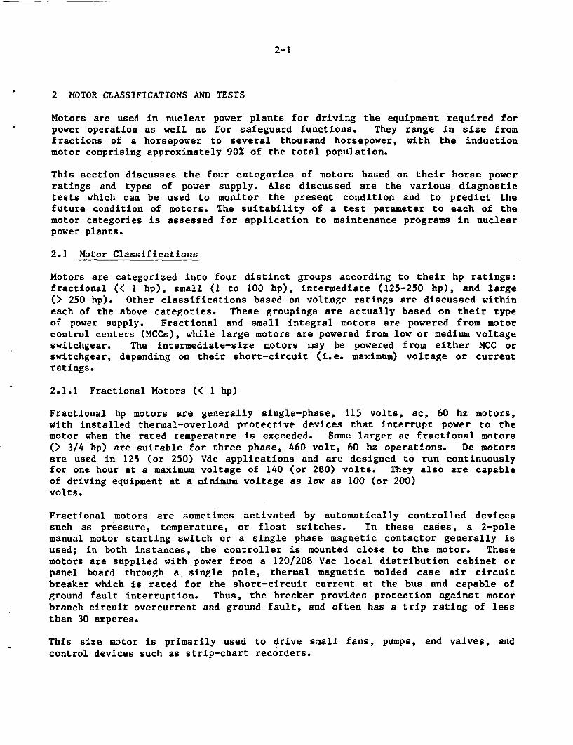
Motors are used in nuclear power plants for driving the equipment required forpower operation as well as for safeguard functions. They range in size fromfractions of a horsepower to several thousand horsepower, with the inductionmotor comprising approximately 90% of the total population.
This section discusses the four categories of motors based on their horse powerratings and types of power supply. Also discussed are the various diagnostictests which can be used to monitor the present condition and to predict thefuture condition of motors. The suitability of a test parameter to each of themotor categories is assessed for application to maintenance programs in nuclearpower plants.
2.1 Motor Classifications
Motors are categorized into four distinct groups according to their hp ratings:fractional (< I hp), small (1 to 100 hp), intermediate (125-250 hp), and large(> 250 hp). Other classifications based on voltage ratings are discussed withineach of the above categories. These groupings are actually based on their typeof power supply. Fractional and small integral motors are powered from motorcontrol centers (MCCs), while large motors are powered from low or medium voltageswitchgear. The intermediate-size motors may be powered from either MCC orswitchgear, depending on their short-circuit (i.e. maximum) voltage or currentratings.
2.1.1 Fractional Motors (< 1 hp)
Fractional hp motors are generally single-phase, 115 volts, ac, 60 hz motors,with installed thermal-overload protective devices that interrupt power to themotor when the rated temperature is exceeded. Some larger ac fractional motors(> 3/4 hp) are suitable for three phase, 460 volt, 60 hz operations. Dc motorsare used in 125 (or 250) Vdc applications and are designed to run continuouslyfor one hour at a maximum voltage of 140 (or 280) volts. They also are capableof driving equipment at a minimum voltage as low as 100 (or 200)volts.
Fractional motors are sometimes activated by automatically controlled devicessuch as pressure, temperature, or float switches. In these cases, a 2-polemanual motor starting switch or a single phase magnetic contactor generally isused; in both instances, the controller is mounted close to the motor. Thesemotors are supplied with power from a 120/208 Vac local distribution cabinet orpanel board through a, single pole, thermal magnetic molded case air circuitbreaker which is rated for the short-circuit current at the bus and capable ofground fault interruption. Thus, the breaker provides protection against motorbranch circuit overcurrent and ground fault, and often has a trip rating of lessthan 30 amperes.
This size motor is primarily used to drive small fans, pumps, and valves, andcontrol devices such as strip-chart recorders.
2-2
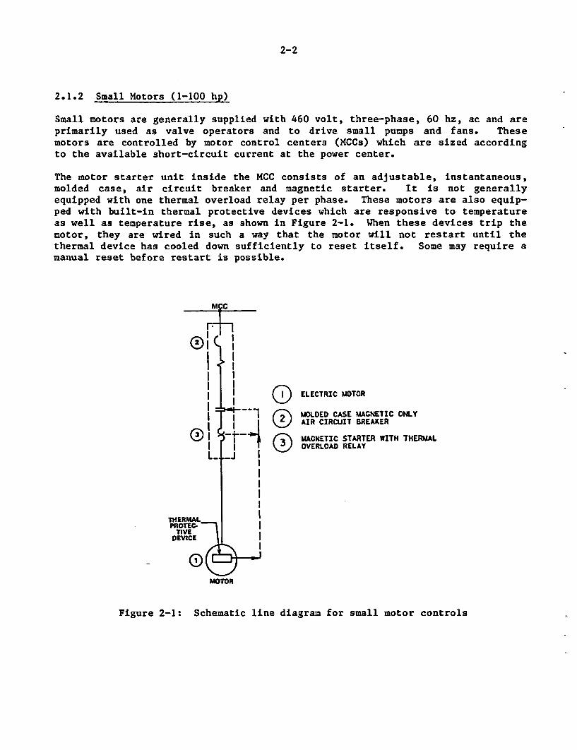
2.1.2 Small Motors (1-100 hp)
Small motors are generally supplied with 460 volt, three-phase, 60 hz, ac and areprimarily used as valve operators and to drive small pumps and fans. Thesemotors are controlled by motor control centers (MCCs) which are sized accordingto the available short-circuit current at the power center.
The motor starter unit inside the MCC consists of an adjustable, instantaneous,molded case, air circuit breaker and magnetic starter. It is not generallyequipped with one thermal overload relay per phase. These motors are also equip-ped with built-in thermal protective devices which are responsive to temperatureas well as temperature rise, as shown in Figure 2-1. When these devices trip themotor, they are wired in such a way that the motor will not restart until thethermal device has cooled down sufficiently to reset itself. Some may require amanual reset before restart is possible.
MCC
I _
I 1I1 I
, @ ELECTRIC MOTOR
1 O OLDED CASE MAGNETIC ONLYAIR CIRCUIT BREAKER
1 5 t"I (\ |MAGNETIC STARTER WITH THERMALI I \ ODYERLOAD RELAYL __
THERMALPROTEC _
DEVICE _
MOTOR
Figure 2-1: Schematic line diagram for small motor controls
2-3
Pump and fan motors generally are continuous-use motors, while valve operatorsare high torque and intermittent-use motors. Valve motors often have threephases and are supplied with power from motor control centers, which contain pro-tection devices and control relays. For non-safety valve motors outside the pri-mary containment, the controllers and protective devices at the MCC should allowfor remote operation of the valve and provide protection for the operator andthe power feeder. Selection of the thermal overload relay and heater depends onthe following basis:
* motor normal load current* motor locked rotor current* allowable motor locked rotor time (safe stall time)* valve stroke time* motor current corresponding to 200 percent normal load* valve pressure/temperature ratings.
Safety-related motor operators located outside the primary containment have con-troller and protective devices which should comply with NRC regulatory guide1.106, Draft, Rev. 2 "Thermal overload protection on motor-operated valves fornuclear power plants," and recommendations made by the manufacturers. One ofthe design conditions in this regulatory guide is that the thermal overload relaytripping contacts should be bypassed automatically upon the actuation of a safetyinjection or an isolation signal. The NRC staff is currently considering thattripping of the overload thermal device should be indicated in the control room,and they also propose that the use of these thermal overload devices be recom-mended for all safety related motor operators.
Motor operators, of the safety or non-safety types, located inside the primarycontainment have additional controller and protective devices for remote opera-tion and protection against electrical penetrations into the primary containment,complying with the NRC regulatory guide 1.63, Rev. 3, February 1987, "ElectricPenetration Assemblies in Containment Structures for Nuclear Power Plants." Thisregulatory guide essentially endorses the IEEE Std-317 (1983) which requires onedual element fuse per phase. Figures 2-2 and 2-3 show the line diagrams formotors outside and inside the primary containment.
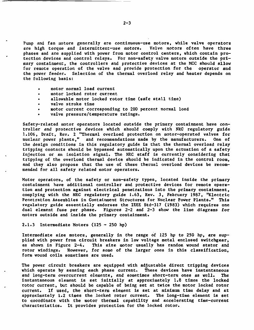
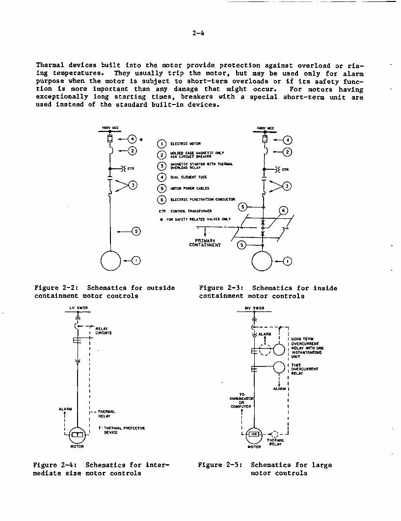
2.1.3 Intermediate Motors (125 - 250 hp)
Intermediate size motors, generally in the range of 125 hp to 250 hp, are sup-plied with power from circuit breakers in low voltage metal enclosed switchgear,as shown in Figure 2-4. This size motor usually has random wound stator androtor windings. However, for some of the larger ones in this classification,form wound coils sometimes are used.
The power circuit breakers are equipped with adjustable direct tripping deviceswhich operate by sensing each phase current. These devices have instantaneousand long-term overcurrent elements, and sometimes short-term ones as well. Theinstantaneous element is set initially at approximately 1.8 times the lockedrotor current, but should be capable of being set at twice the motor locked rotorcurrent. If used, the short-term element is set at minimum time delay and atapproximately 1.2 times the locked rotor current. The long-time element is setto coordinate with the motor thermal capability and accelerating time-currentcharacteristics. It provides protection for the locked rotor.
2-4
Thermal devices built into the motor provide protection against overload or ris-ing temperatures. They usually trip the motor, but may be used only for alarmpurpose when the motor is subject to short-term overloads or if its safety func-tion is more important than any damage that might occur. For motors havingexceptionally long starting times, breakers with a special short-term unit areused instead of the standard built-in devices.
4410V M1CC
) _0
f-3E CTR
P>)
3 ELECTRIC MOTORo OLDED CASE MAGNETIC ONLYAIR CIRCNIT BREAKER
I 4OVNETIC STARTER WITH THERMALOVERLOAD RELAV
( DUAL ELEMENT FUSE
O MOTOR POWER CABLES
i) ELECTRIC PENETRATION CONDUCTOR
CTR CONTROL TRANSFORMER
* FOR SAFETY RELATED VALVES ONLY
4a0Y MCC
1) _CTR
-40PRIMARY
CONTAINMENT
OFigure 2-2: Schematics for outsidecontainment motor controls
LV SWGR
RELAYCIRCUITS
Figure 2-3: Schematics for insidecontainment motor controls
MV SWOR
ALARM' lt II LONG TERM
, OVERCURRENTC RELAY WITH ONE
C _INSTANTANEOUSUNIT
I TIMEOVERCUR RENTRELAY
ALARM I
TO IANNUNCATR
COMPUTER
t
THERMAL
MOTOR RELAY
I
ALARM II--THERMAL
t , RELAYI II I
__ I T THERMAL PROTECTIVEI (2 DEVICE
MOTOR
Figure 2-4: Schematics for inter-mediate size motor controls
Figure 2-5: Schematics for largemotor controls
2-5
2.1.4 Large Motors (> 250 hp)
Large motors are often equipped with many protective devices such as overcurrent,overvoltage, and under frequency protective relays, etc. because of their highreplacement cost. These motors are continuously running or are in standby mode,and are started infrequently. The power supply is from medium-voltage metal cladswitchgear, with medium voltage air or vacuum circuit-breakers. The typical sup-ply voltage levels are 2.3, 4.0, 6.6, and 13.2 kv. The size of the switchgear isprimarily based on the short-circuit current (maximum current) and the motorvoltage ratings. Figure 2-5 shows a typical motor line diagram.
Large motors are protected from phase overcurrent either by three single-phaserelays or one three-phase relay. If the locked rotor current of a motor exceedsa certain fraction of the symmetrical three-phase fault current available at thesupply switchgear, the motor is further protected from phase imbalance by provid-ing phase differential relays. Vertical outdoor pump motors above 2.3 kv uselightning arrestors and surge capacitors. Motors rated at 13.2 kv are generallyprovided with surge arresting capabilities located between the motor and thesurge arrestor. Motors driving high inertial loads that require an accelerationtime longer than 10 seconds usually are analyzed individually for protection dur-ing starting and acceleration.
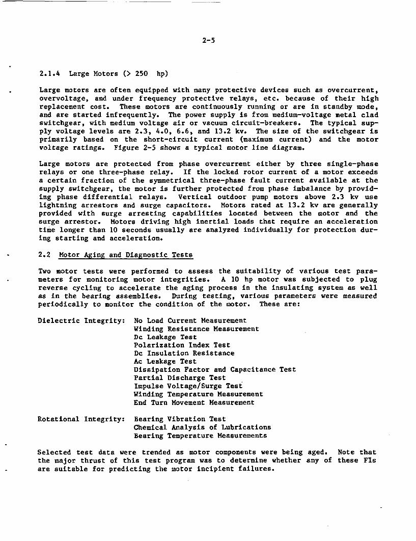
2.2 Motor Aging and Diagnostic Tests
Two motor tests were performed to assess the suitability of various test para-meters for monitoring motor integrities. A 10 hp motor was subjected to plugreverse cycling to accelerate the aging process in the insulating system as wellas in the bearing assemblies. During testing, various parameters were measuredperiodically to monitor the condition of the motor. These are:
Dielectric Integrity: No Load Current MeasurementWinding Resistance MeasurementDc Leakage TestPolarization Index TestDc Insulation ResistanceAc Leakage TestDissipation Factor and Capacitance TestPartial Discharge TestImpulse Voltage/Surge TestWinding Temperature MeasurementEnd Turn Movement Measurement
Rotational Integrity: Bearing Vibration TestChemical Analysis of LubricationsBearing Temperature Measurements
Selected test data were trended as motor components were being aged. Note thatthe major thrust of this test program was to determine whether any of these FIsare suitable for predicting the motor incipient failures.
2-6
Another test program involving diagnostic tests on a naturally failed 400 hpmotor was conducted to determine the failure causes and to assess the aged condi-tion of the stator insulating system. The motor had served a test reactor facil-ity for over 20 years to drive one of its recirculating pumps. Since the motorstator winding was constructed with ninety (90) individual form wound coils, eachcoil was separated for performing dielectric tests. The variation in aging cha-racteristics of the coils was determined by comparison of the individual testdata with baseline data corresponding to an insulating system exposed to 20 yearsof service. The dielectric tests performed on this motor winding include:
Dc Resistance TestSurge TestDc Leakage TestAc Dissipation Factor TestAc Capacitance TestAc Leakage Test
* Ac High Potential Test
The test procedures and results from the two test programs are described indetail in the second and third volumes of this NUREG. The discussions in thefollowing section on various motor functional indicators are based on resultsfrom these two test programs. Information was also obtained from discussionswith experts on this subject, test equipment manufacturers, plant maintenanceengineers, and motor manufacturers.
2.3 Dielectric and Bearing Tests
The first phase of the NPAR study (7) identified all modes, causes, and mecha-nisms of motor failures based on operating experience data from nuclear powerplants. The study provided an extensive list of functional indicators for moni-toring the dielectric, rotational, and mechanical integrities of motors. Thissecond phase study evaluated each of these functional indicators for its suit-ability to motor maintenance programs in nuclear facilities. A discussion ofeach functional indicator is provided.
A review of various test methods available in industry standards, such as IEEE,ASME, ANSI, AFBMA, was conducted. A large number of these tests are currentlyused in repair and rewind shops to recondition motors. Some of them are alsoperformed by manufacturers for qualifying the design of motor subcomponents.Thus, there exist many test methods that can potentially be used in the plantmaintenance programs to monitor the condition of motors.
The basic principles of each test method and its applicability, limitations, andsource of errors are discussed in Appendix A on periodic tests, Appendix B onsurveillance tests, and Appendix C on continuous monitoring and inspection pro-grams. Those test parameters considered in the two motor test programs areincluded in these discussions under the dielectric and bearing tests.
2.3.1 Dielectric Tests
Dielectric tests are performed on the insulating systems, specifically the motorstator windings. Dc Resistance and Polarization Index are the most common tests
2-7
performed in motor maintenance programs. Other tests which are available areac/dc leakage, power factor/dissipation-factor/capacitance, surge, dc windingresistance, and partial discharge. For certain insulating materials the loose-ness of the coils within stator slots can be monitored by the end turn movementmeasurements. In addition, trends in motor running current (load or no-load) andwinding temperature are other potential indicators of abnormalities in thedielectric integrity. These two parameters could be included in one of the testor monitoring activities involving performance evaluation. Periodic inspectionof the insulation is one of the most important maintenance activities and shouldnot be given any less importance than the above tests.
(1) Dc Insulation Resistance/Polarization Index Tests
These two parameters (13) provide an average assessment of insulation conditionand detect the presence of surface contamination or humidity. The tests aresuitable for all motors, independent of their size, type and supply voltagelevel.
The most probable failure mode for small motors used in motor operators forvalves is winding and lead insulation failure. Since the motors do not operatefor long periods, bearing failure is much less likely to occur. The generalelectrical condition of the winding and lead insulation may be determined byperiodic dc insulation resistance tests and polarization index tests. If the PIis low, it is an indication that leakage is relatively continuous and theinsulation is not charging. For most insulating systems used in nuclear safety-related motors, a polarization index of at least 2 would be expected. A lowinsulation resistance also would be indicative of trouble either from surfacecontamination or internal imperfections or deterioration. Since most valve actu-ator motors are sealed, the probable cause of low insulation resistance would beits deterioration rather than surface contamination. The results of periodicmeasurements should be compared to establish the trend of the readings. If adeteriorating trend is observed, there will be a greater probability of insula-tion failure during periods of thermal stress caused by rapid cycling of theassociated valve or overload during a design basis accident.
Both insulation resistance and polarization index are considered to be go/no gotests. They should be performed prior to starting a motor after a long shutdownor prior to performing a high potential test. These parameters failed to provideany early indication of insulation deterioration in both motor test programs.However, an upward trend in either test parameter indicates hardening and dryingof insulating system, which decreases the mechanical strength of the materialleading to developing cracks. These tests are performed from the motor controlcenter, thereby including the power cables in the circuit.
(2) Ac/Dc Leakage Hipot Tests
Insulation leakage tests include a gradual increase in voltage as leakage currentis measured and usually conclude with a high potential (HiPot) test. This test isgenerally performed on motors of 3,000 V and higher, and a curve of leakage cur-rent versus voltage is plotted. The leakage current should be fairly linear andthe insulation resistance should remain stable until a point is reached at
2-8
which current begins to increase rapidly with voltage. The test is then stopped(14) to prevent complete breakdown of the insulation, or it is stopped at a pre-determined voltage if no breakdown occurs. An increase in the leakage currentindicates cracks or deterioration of the insulation.
The dc leakage current measurements are found to be an alternate to the insula-tion resistance test in which case the resistance is measured instead of leakagecurrent. Unless the insulation is severely degraded, the leakage currentmeasurement is too small to exhibit any trends and hence, does not provide anyuseful information with regards to its condition. The ac leakage current (hipot)test, on the other hand, could be destructive since test voltages well above themotor rating are used. This test is an endurance test and can detect insulationbreakdown at an incipient stage. However, because it can be destructive, thistest is not recommended for preventive maintenance programs.
(3) Power Factor/Dissipation Factor/Capacitance Tests
Power factor and power factor tip-up tests are ac insulation tests that determinethe ratio of the resistance current to the total charging current. For perfectinsulation, the power factor should remain constant with increasing voltage.However, if partial discharges occur in cavities within the insulation, anincrease in the power factor will occur when the inception volt age (the voltageat which discharge begins) is exceeded. This test is called a power factor tip-up test. Periodic test results are compared to determine if the inception voltageis decreasing, thus indicating deterioration of the insulation.
Dissipation factor tests are similar to power factor tests except that the ratioof the capacitive current to the resistive current is measured. As with thepower factor, the dissipation factor should remain relatively constant withincreasing voltage. Trending of the voltage at which the dissipation factorchanges may be used to trend deterioration of the insulation. A larger dissipa-tion factor, when compared to a baseline value for good insulation, indicates thepresence of voids and cracks. These defects allow paths for leakage current andare sources of corona discharges. Like dissipation factor, the capacitancemeasurements of the insulation indicate insulation deterioration such as thinn-ing. The diagnostic tests on the 400 hp failed motor support the conclusion thatboth dissipation factor and capacitance values could be used to detect incipientinsulation deterioration due to aging.
Power factor tip-up tests are reserved for high voltage motors (4000V and up) andare performed only on motors with insulation systems that are susceptible to par-tial discharge problems. These tests are lengthy and are difficult to performdue to the nature of the test equipment.
(4) Voltage Impulse/Surge Tests
Surge testing is used on motor windings to detect turn-to-turn failures andincorrect electrical connections. Although it has not been widely used in main-tenance programs, recent technological developments have provided the tools forperforming these tests in power plants. A comparison of the waveshapes of volt-age pulses between a good and bad winding can reveal insulation failures.
2-9
A turn short in one of the form wound coils in the 400 hp motor and the firstdetection of stator ground in the 10 hp motor were revealed by surge tests. Thetest can be performed at the motor control center or switchgear, and includesboth the cable and the motor windings. Disconnection for further testing wouldbe performed only if a problem is indicated and isolation is necessary to deter-mine the motor or the cable is failing.
With the available test equipment this test is limited to low voltage motors. Thetest is a good tool for detecting turn short conditions. If a turn short remainsundetected, application of a low voltage gradient across it will cause currentleakage through the insulation, resulting in heating. A temperature rise furtherreduces dielectric strength, which causes increased current and further heating.Ultimately, this cascading effect will cause insulation failure. The tendency ofa weak spot to cascade to failure is worsened during periods of motor overheatingfrom overload and rapid cycling, since the additional temperature rise rapidlyreduces the dielectric strength of the weak spot in the insulation.
(5) Motor Running Current Test
In the two motor test programs, monitoring of this test parameter did not provideany information to assess insulation condition as aging occurred. Also, thereare numerous factors which can produce current fluctuations which make the inter-pretation of results from this test uncertain.
In some cases, the running current indicates the condition of the driven equip-ment if there exist any rotational resistances. When a motor is subjected to anoverload condition, this may be indicated by higher running current. If it isleft for a long duration, overheating of the windings may result in insulationburning.
(6) Partial Discharge Test
Partial discharge tests are performed to determine the inception or thresholdvoltages at which partial discharges occur. The power supply for a partial dis-charge test must be capable of providing rated phase-to-ground volt age and thecharging current required by the cable and winding insulation system. In thesmall motor testing, the trend in inception voltage indicated slot wedge degra-dation in the stator slot while the small motor was subjected to acceleratedaging.
Like surge testing, this parameter is a good indicator for discharges at localdefects such as hot spots and voids. However, for low voltage motors this testis difficult to perform. Unless advanced test equipment is available to detectlow voltage discharges this test is recommended only for higher volt age motors.Since it requires higher ac voltage, this test should be performed with caution,otherwise this test could induce degradation in the insulating material.
(7) Dc Winding Resistance Test
Dc resistance of the stator windings of the 10 hp motor were found to remainrelatively constant and the trend of insulation degradation was not revealeduntil there was a break in the windings. However, this indicator could detect
2-10
unbalanced windings, bad connections and broken wire. Comparisons of windingresistance measurements with previous readings may indicate significant deterior-ation in turn-to-turn insulation for the winding. This test, although easy toperform in a plant environment, does not seem to detect any defects in the insu-lation at an incipient stage.
2.3.2 Bearing Tests
The operating experience data assessment concluded that the dominant bearing pro-blems were due to excessive or insufficient lubrication, wear of bearing surfacesor misalignment, leakage of lube oil through seals and gaskets, and intrusion ofwater or steam which changes the lubricity and viscosity of lubricant. The studyalso determined that the functional indicator that detect incipient bearingdegradation are (1) Vibration and temperature measurement, (2) Lubrication analy-sis, and (3) a good inspection program.
(1) Vibration/Spike Energy
Each motor has a characteristic vibration signature when it is in good condition.This signature reflects bearing performance, electrical field balance, structuralintegrity and rotor shaft alignment. Table 2-1 provides the frequency character-istics of various fault conditions one would encounter in motor performance(15,16). One of the more sophisticated monitoring schemes uses Fast FourierTransform (FFT) instrumentation coupled to a computer analyzer that periodicallycompares the results of the FFT to the vibration signature of the healthy system.Changes in amplitude of the various frequencies are trended and, if potentiallydangerous, an alarm is activated (17). Such a system installed at a nuclearpower plant would continuously monitor pumps and their drive systems. It must berecognized that such sophisticated systems are presently justified only forlarge, difficult-to-replace machinery.
Displacement, velocity and acceleration signatures can be measured for diagnosingfaults in motor components (18). The results can be displayed in terms of fre-quency using a high-resolution FFT frequency analyzer. Velocity is a function ofboth displacement and frequency, and the lines defining zones of severity areconstant velocity. Problems are, therefore, better indicated with a velocitymeasurement rather than displacement, regardless of whether it is due to anunbalance or a worn bearing. However displacement recordings are also a measureof vibration severity provided the frequency is known. The disadvantage to velo-city readings is that below 600 cpm the vibration amplitudes are small and aredifficult to measure. Displacement is a better parameter to monitor for thisreason. Continuous monitoring systems often are used to monitor equipment whichrequires high operational reliability, long-term stability and immunity toadverse environmental conditions. Because of the initial cost of such a system,this type is typically applied to large motors.
Periodic vibration measurements are generally made as a part of surveillancetesting and as good maintenance practice. Portable instruments, such as IRD,Bruel & Kjaer vibration/spike energy analyzers, are now available for takingmeasurements at a regular interval. The periodicity for these measurementsdepend upon the average operating time before failure of the motor. A built-inspectrum analyzer is used to identify the root-cause of. vibration problemsdetected during the periodic measurements.
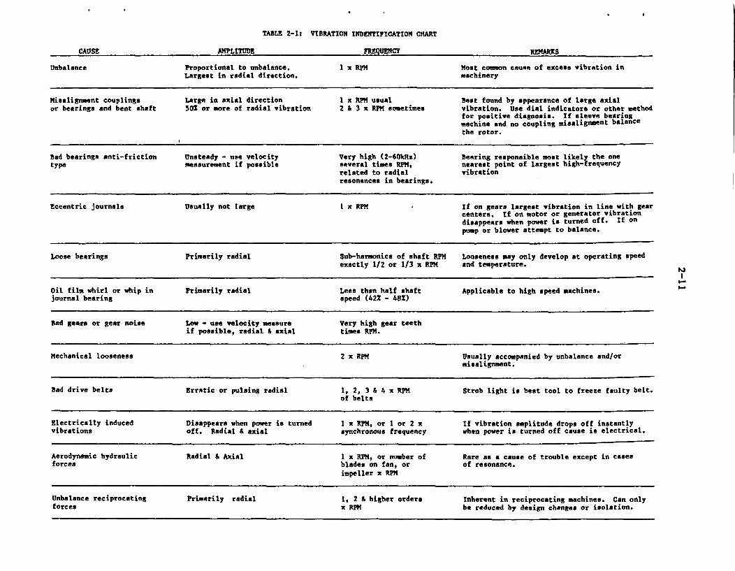
TABLE 2-1: VIBRATION INDENTIFICATION CHART
CAUSE AMPLITUDE FREQUENCY REMARKS
Unbalance Proportional to unbalance. 1 x RPM Most common cause of excess vibration inLargest in radial direction. machinery
Misalignment couplings Large in axial direction I x RPM usual Beat found by appearance of large axialor bearings and bent shaft 501 or more of radial vibration 2 & 3 x RPM sometimes vibration. Use dial indicators or other method
for positive diagnosis. If sleeve bearingmachine and no coupling misalignment balancethe rotor.
Bad bearings anti-friction Unsteady - use velocity Very high (2-60kHz) Bearing responsible most likely the onetype measurement if possible several times RPM, nearest point of largest high-frequency
related to radial vibrationresonances in bearings.
Eccentric journals Usually not large I x RPM If on gears largest vibration in line with gearcenters. If on motor or generator vibrationdisappears when power is turned off. If onpump or blower attempt to balance.
Loose bearings Primarily radial Sub-harmonics of shaft RPM Looseness may only develop at operating speedexactly 1/2 or 1/3 x RPM and temperature.
Oil film whirl or whip in Primarily radial Less then half shaft Applicable to high speed machines.journal bearing speed (422 - 482)
Bad gears or gear noise Low - use velocity measure Very high gear teethif possible, radial & axial times RPM.
Mechanical looseness 2 x RPM Usually accompanied by unbalance and/ormisalignment.
Bad drive belts Erratic or pulsing radial 1, 2, 3 & 4 x RPM Strob light is best tool to freeze faulty belt.of belts
Electrically induced Disappears when power is turned I x RPM, or I or 2 x If vibration amplitude drops off instantlyvibrations off. Radial & axial synchronous frequency when power is turned off cause is electrical.
Aerodynamic hydraulic Radial & Axial I x RPM, or number of Rare as a cause of trouble except in casesforces blades on fan, or of resonance.
impeller x RPM
Unbalance reciprocating Primarily radial 1, 2 & higher orders Inherent in reciprocating machines. Can onlyforces x RPM be reduced by design changes or isolation.
I-
2-12
Bearings and enclosures are typically equipped with transducers for monitoringthe vibration characteristics of motors.
(2) Acoustic Emission
An acoustic emission test is a dynamic test method in that it monitors theresponse of a material upon application of stress (19). It is defined as a tran-sient elastic wave, generated by the rapid release of energy at ultrasonic fre-quencies from a localized source within a material. As applied to non-destruc-tive testing (NDT), the emissions occur when a material is stressed. Elasticenergy is released as a result of sudden material displacement due to crack pro-pagation, dislocation avalanching in the plastic zone at the edge of a discon-tinuity, and numerous other. lesser mechanisms.
Reactor coolant pump motors are large vertical, squirrel-cage induction machinesfitted with heavy flywheels to increase the rotational inertia of the motor.Rotational inertia prolongs the pump's coast-down, thus assuring a more gradualloss of main reactor coolant flow to the core in the event that pump power islost. Arkansas Power & Light Company (20) recently utilized acoustic emissiontechniques for testing flywheels on their RCP motors, which allowed them to avoidthe time-consuming disassembly of restraint girders, rotor, and upper guide bear-ings, which was required when other conventional methods were used. The acousticemission tests also can be used to monitor the enclosure and support integrity,for detecting leaks, and sensing damage or wear in rotating equipment.
(3) Lubrication Analysis
For motors with oil-based lubrication systems with reservoirs, lubricant samplingfor condition and contamination may be performed. Such tests of the lubricatingoil will preclude the need for, and usefulness of lubricant testing. For grease-packed bearings, lubricant sampling is not practical. Generally periodic chang-ing and repacking is performed.
2.4 Temperature Monitoring
Two common locations for monitoring temperature in motors are bearing housingsand winding slots. If bearing temperatures rise above the manufacturer's rating,deterioration of lubricant and/or damage to the bearing may occur. While not assensitive as vibration analysis, temperature monitoring may indicate certain pro-blems, such as significant lubricant deterioration prior to vibrational changes.Winding and stator-core problems will be indicated by increased winding or slottemperature. Such problems include motor overload, excessive starts and damageto lamination insulation. Motor slot temperature detectors are installed at thetime of manufacture.
Because temperature monitoring of all motors for valve operators would be costprohibitive and return little useful information, a continuous temperature moni-toring system is not recommended. However, one method of determining if a motorhas experienced thermal overloads during an interval between inspections is theapplication of temperature indicating labels that permanently change color at aparticular temperature (21). While not useful for determining the exact cause of
2-13
the temperature rise, such labels indicate that further investigation of valveoperator condition and operating practices is required. A close scrutiny ofinsulation resistance tests is then needed to show that permanent damage to theinsulation has not occurred. If there are repeated indications of high tempera-tures, investigation of the application and sizing of the motor should be per-formed. As of this writing, temperature-indicating labels are not known to beused in the nuclear industry as a condition monitoring technique.
For some large motors equipped with sleeve bearings, an increase in the lubri-cating oil temperature indicates degradation of the bearing.
2.5 Physical Inspection
Internal inspection of motors can reveal physical deterioration in the insulationand loosening of winding materials that may not be evident from other tests, suchas insulation resistance. Powdering of insulation materials from chafing willgenerally leave deposits in dead air spaces within the motor. Usually loosenessof end-turn support and binding material is easy to detect. Periodic physicalinspection is not often performed due to its costs and the need for not disturb-ing the physical condition of the motor. However, whenever the endbells of themotor are removed for bearing replacement or maintenance, a physical inspectionshould be made.
Appendix C discusses various inspection activities that can be included in aplant maintenance program. The "10-point" comprehensive list describes all pos-sible checks required to monitor the physical condition of a motor.
2.6 Miscellaneous Tests
The end turn movement of the stator assembly provides useful information on thelooseness of windings in the stator slots after sufficient breakdown in the insu-lating materials. However, this requires installing monitoring devices on thestator end turns and usually does not warrant the benefit.
Non-destructive testing can be performed on large motors for detecting metalcracks or voids. However, the cost of performing these tests can be too prohibi-tive to be included in a motor maintenance program.
Those pumps and valves that are important to plant safety are subjected to sur-veillance testing as required by the plant tech specs. The pumps are tested fortheir flow and pressure characteristics while valves are tested for strokingtimes. There exist almost no current regulatory requirements for testing themotors driving these components. Some utilities, however, have already includedcertain tests such as motor running current, speed, and valve stroking measure-ments in their surveillance test programs. Appendix B discusses some of thesetest methods in detail.
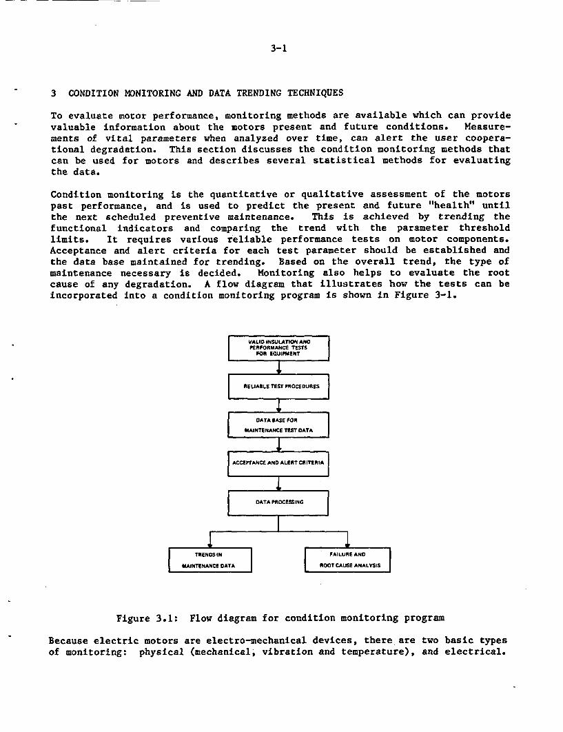
3-1
3 CONDITION MONITORING AND DATA TRENDING TECHNIQUES
To evaluate motor performance, monitoring methods are available which can providevaluable information about the motors present and future conditions. Measure-ments of vital parameters when analyzed over time, can alert the user coopera-tional degradation. This section discusses the condition monitoring methods thatcan be used for motors and describes several statistical methods for evaluatingthe data.
Condition monitoring is the quantitative or qualitative assessment of the motorspast performance, and is used to predict the present and future "health" untilthe next scheduled preventive maintenance. This is achieved by trending thefunctional indicators and comparing the trend with the parameter thresholdlimits. It requires various reliable performance tests on motor components.Acceptance and alert criteria for each test parameter should be established andthe data base maintained for trending. Based on the overall trend, the type ofmaintenance necessary is decided. Monitoring also helps to evaluate the rootcause of any degradation. A flow diagram that illustrates how the tests can beincorporated into a condition monitoring program is shown in Figure 3-1.
IVALIO INSULATION ANDPERFORMANCE TESTS
FOR EQUIPMENT I
[[
RELIABLE TEST PROCEDURES
DATA BASE FOR
MAINTENANCE TEST DATA
.iI1zIACCEPTANCE AND ALERT CRITERIAI.
DATA PROESSING
I
ITRENDS IN
I MAINTENANCE DATAI
FAILURE AND
ROOT CAUSE ANALYSIS
Figure 3.1: Flow diagram for condition monitoring program
Because electric motors are electromechanical devices, there are two basic typesof monitoring: physical (mechanical, vibration and temperature), and electrical.
3-2
Most physical measurements, such as bearing vibration and winding temperature,must be performed with the motor operating. On the other hand, most electricaltests require the motor to be out of service, but not necessarily disconnectedfrom its power leads.
The condition monitoring techniques that are applicable to the various types ofmotors depend on their size and voltage level, and the type of application (suchas continuous duty or intermittent duty). In general, the tests for small andintermittent duty motors, such as valve operators, may be limited to electricaltests of insulation resistance, polarization index, and stator coil resistances.For larger, higher voltage, continuous duty machines, many electrical and physi-cal tests may be used. In most cases during condition monitoring, the motor willnot be disconnected from its power leads or uncoupled from its load. Therefore,most measurements will be made on combinations of motors and other system ele-ments, such as electrical tests of windings and power leads, or vibration testswhich may include vibrations from the coupled load. In the case of vibration,some monitoring systems allow filtering or frequency analysis to assist in iso-lating the source of trouble.
Development in the condition monitoring of motors and motor operators is proceed-ing along two paths:
(a) Analysis and trending of data from maintenance tests presently performed,such as megger tests, polarization index, and stroke times.
(b) Introduction of new test methods, such as signature analysis (MOVATS) andpower factor and surge testing of the motor insulation.
The high temperatures occurring during motor starting and from ambient tempera-ture are the major contributors to motor insulation deterioration and failure.Widely used tests to monitor the insulation in motors are meggering and polariza-tion index. Several studies sponsored by EPRI (22,23) and by others (24) haverecommended additional tests for monitoring the condition of the insulation,including power factor tip-up and controlled overvoltage tests.
Many limitations affect a condition monitoring program. For periodic tests ofmotors inside containment, access is limited by operating and radiation condi-tions. With regard to condition monitoring of the physical parameters of largermotors outside containment, the cost of sophisticated monitoring may preclude allbut the largest motors.
Another consideration in trending is the usefulness of the monitored parametersfor detecting incipient failures with adequate time for corrective action. Manymonitoring methods detect the initial stages of failure and serve to minimizedamage rather than to prevent it. For the present, knowing that the initialstages of failure have occurred, may make condition monitoring worthwhile, evenif the existing methods do not always provide long lead times between detectionand failure. Assuming corrective action is taken, prevention of significantdamage reduces cost of repair. In addition, removal of a failing component fromservice prevents any reliance being placed upon it to perform its safetyfunction.
3-3
Condition monitoring techniques should not create significant potential for mal-function. Therefore, it is preferable not to require disruption of power andcontrol circuits to a motor, since this introduces the possibility of improperreconnection. In the case of large pump motors, an improper reconnection can bedisastrous, since it could cause reverse rotation of the motor, which often willcause severe damage to the pump.
The cost of condition monitoring and the value of the information received mustbe considered in choosing alternatives. It must be recognized that no correla-tion has been shown between the results of condition monitoring and the abilityto withstand accident conditions. However, it must be assumed that a motor withdetectable levels of deterioration may not be capable of required operation dur-ing accident conditions.
3.1 Condition Monitoring Techniques
The basic types of condition monitoring are:
• Vibration detection (continuous or periodic, with or without analysis) forbearing and rotor condition.
* Temperature monitoring of bearings and windings (generally continuous).* Lubricant analysis (periodic, generally limited to oil reservoir lubricat-
ing systems).* Physical inspection of internals.* Electrical insulation tests.* Insulation resistance/polarization index.
Ac/Dc insulation leakage tests.Dissipation factor/capacitance and power factor tip-up.Partial discharge.
* Surge/impulse voltage tests.
The Ac leakage (hipot) test is not recommended unless the test is performed withutmost caution for not exceeding the breakdown voltage of aged coils. The par-tial discharge test, on the other hand, is a good test for condition monitoringand trending; but the test setup is difficult to perform in a plant environment,especially for small motors. Note that for condition monitoring and trendingpurposes, baseline data for each test parameter corresponding to the post-instal-lation condition of the motor should be determined first.
Table 3-1 summarizes the maintenance activities and functional indicators whichcomprise a condition monitoring program intended to detect and monitor the effectof aging degradation. The usefulness of each indicator and its trends withrespect to a baseline or threshold value is discussed. This information is basedon the two BNL motor test, expert judgment, and prior work.
Condition monitoring techniques discussed here consist of three distinct dif-ferent types of evaluations. These include go/no go condition monitoring, localdegradation detection monitoring, and average deterioration monitoring. Each ofthese conditions can be achieved by monitoring certain functional indicators. Acomprehensive physical inspection program can provide the greatest cost/benefitvalue, specifically to those motors which are accessible during normal opera-tions. Specific frequency is determined based on environment, importance, andduty. This activity can contribute information to each of the three monitoringtechniques mentioned above.
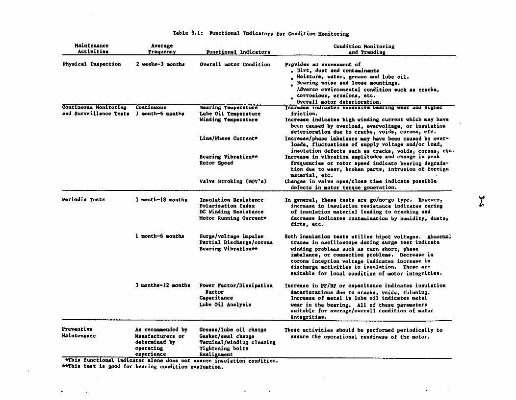
Table 3.1: Functional Indicators for Condition Monitoring
Maintenance Average Condition MonitoringActivities Frequency Functional Indicators and Trending
Physical Inspection 2 weeks-3 months Overall motor Condition Prpvides an assessment of. Dirt, dust and contaminants
M Moisture, water, grease and lube oil.R Bearing noise and loose mountings.Adverse environmental condition such as cracks,corrosions, erosions, etc.Overall motor deterioration.
Continuous Monitoring Continuous Bearing Temperature Increase indicates excessive bearing wear and higherand Surveillance Tests 1 month-6 months Lube Oil Temperature friction.
Winding Temperature Increase indicates high winding current which may havebeen caused by overload, overvoltage, or insulationdeterioration due to cracks, voids, corona, etc.
Line/Phase Current* Increase/phase imbalance may have been caused by over-loads, fluctuations of supply voltage and/or load,insulation defects such as cracks, voids, corona, etc.
Bearing Vibration** Increase in vibration amplitudes and change in peakRotor Speed frequencies or rotor speed indicate bearing degrada-
tion due to wear, broken parts, intrusion of foreignmaterial, etc.
Valve Stroking (MOV's) Changes in valve open/close time indicate possibledefects in motor torque generation.
Periodic Tests 1 month-18 months Insulation Resistance In general, these tests are go/no-go type. However,Polarization Index increase in insulation resistance indicates curingDC Winding Resistance of insulation material leading to cracking andMotor Running Current* decrease indicates contamination by humidity, dusts,
dirts, etc.
I month-6 months Surge/voltage impulse Both insulation tests utilize hipot voltages. AbnormalPartial Discharge/corona traces in oscilloscope during surge test indicateBearing Vibration** winding problems such as turn short, phase
imbalance, or connection problems. Decrease incorona inception voltage indicates increase indischarge activities in insulation. These aresuitable for local condition of motor integrities.
3 months-12 months Power Factor/Dissipation Increase in PF/DF or capacitance indicates insulationFactor deteriorations due to cracks, voids, thinning.
Capacitance Increase of metal in lube oil indicates metalLube Oil Analysis wear in the bearing. All of these parameters
suitable for average/overall condition of motorintegrities.
Preventive As recommended by Grease/lube oil change These activities should be performed periodically toMaintenance Manufacturers or Gasket/seal change assure the operational readiness of the motor.
determined by Terminal/winding cleaningoperating Tightening boltsexperience Realignment
*This functional indicator alone does not assure insulation condition.**This test is good for bearing condition evaluation.
3-5
The second input for the condition monitoring program comes from data obtainedfrom motors with continuously monitored parameters and from data obtained formotors which drive pumps, fans, and valves. The driven equipment must be operat-ed periodically to determine design functional integrity (go/no go condition) inaccordance with the tech specs while performing surveillance tests. Theseinclude pump flow and discharge pressure, pump speed, motor current, lube oillevel or pressure, valve stroke times, etc. A small manpower increment of addi-tional data collecting and analysis can provide information for monitoring theaverage condition of the motor.
Change in temperature of bearings, lube oil, or windings is the first indicationof trouble or deterioration occurring in the corresponding component. Hence,these parameters should be evaluated against the previously recorded data as wellas against the operational and environmental conditions to assess the bearing andwinding conditions. Increase in bearing vibration level should be further evalu-ated in assessing the root cause of this abnormal condition as described in table2-1.
Periodic tests comprise the third input into the condition monitoring program andinclude testing which most utilities presently perform such as insulation resis-tance and polarization index. However, use of this data has been limited to ago/no go evaluation. Motor testing programs have shown that these two insulationtests along with dc winding resistance and motor running current provide informa-tion only suitable for go/no go type of condition monitoring. However, anincrease in insulation resistance is an indication of insulation hardening, thusincreasing the potential for cracking, while a decrease indicates insulation con-tamination. Even for the 20 year old motor insulation tested, this parameter didnot indicate any age-related deterioration.
Both the surge test and the partial discharge (corona) test are suitable fordetecting as well as monitoring local defects such as turn shorts, hot spots,discharges, break in the windings. These defects constitute the initiation ofthe insulation degradation that could lead to complete stator burnouts. Earlydetection and monitoring can avoid catastrophic motor failures. It should benoted that both of these tests utilize high potential input for exaggerating theeffects of the flaws. Surge test utilizes dc potential and the available testequipment is suitable for small random wound motors (F 600 volts rating). Thepartial discharge test is reserved for high voltage motors in which case thelocal discharges can be seen without raising the test voltage much higher thanthe rated voltage. These tests should be performed periodically (at least twicea year) for early detection of localized flaws.
The last kind of tests which are good for monitoring the average condition of themotor components include power factor/dissipation factor and capacitance tests,and periodic chemical analysis of lube oil. Increase in dielectric factors is adefinite indication of insulation deterioration due to cracks, voids, or thinn-ing, whereas increase in metal wear in lube oil indicates bearing degradation.Since these tests provide average parameters, they should be performed less fre-quently (at last once a year or plant outage) than the previously mentionedtests.
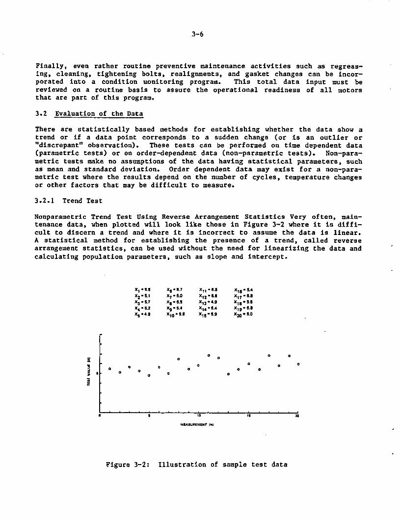
3-6
Finally, even rather routine preventive maintenance activities such as regreas-ing, cleaning, tightening bolts, realignments, and gasket changes can be incor-porated into a condition monitoring program. This total data input must bereviewed on a routine basis to assure the operational readiness of all motorsthat are part of this program.
3.2 Evaluation of the Data
There are statistically based methods for establishing whether the data show atrend or if a data point corresponds to a sudden change (or is an outlier or"discrepant" observation). These tests can be performed on time dependent data(parametric tests) or on order-dependent data (non-parametric tests). Non-para-metric tests make no assumptions of the data having statistical parameters, suchas mean and standard deviation. Order dependent data may exist for a non-para-metric test where the results depend on the number of cycles, temperature changesor other factors that may be difficult to measure.
3.2.1 Trend Test
Nonparametric Trend Test Using Reverse Arrangement Statistics Very often, main-tenance data, when plotted will look like those in Figure 3-2 where it is diffi-cult to discern a trend and where it is incorrect to assume the data is linear.A statistical method for establishing the presence of a trend, called reversearrangement statistics, can be used without the need for linearizing the data andcalculating population parameters, such as slope and intercept.
Xi . 5.5X2-5.1X -5.7x4 52X5 4.8
Xs - 5.7X7 .5.0X8-a5X 9 - 5.4XI(o 5.3
XI, -S.3
XI2 ' 8.X13 . 4.gX1 4 - 5.4XI 5, 5.9
Xis , 5.4X17 , 6.8XIS . 5.6
X 1 9 * 6.8X2 0 5 .0
9
Is
139
0a
0 00
a0 a
a
a a0 0
G aa a
S 10
MIASUREMMNT IN)
Figure 3-2: Illustration of sample test data
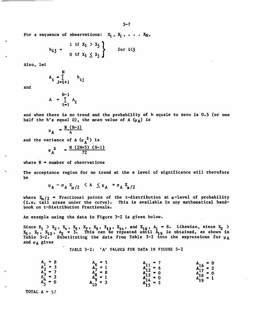
3-7
For a sequence of observations: X1, X1 , . * XN,
hij 1 if Xi > Xj } for i<j
0 if Xi < Xj
Also, let
N
JPi+ 1
and
N-1A Ai
i-i
and when there is no trend and the probability of h equals to zero is 0.5 (or onehalf the h's equal 0), the mean value of A (PA) is
N (N-1))'A 4
and the variance of A (a 2) isA.
2 N (2N+5) (N-1)aA 72
where N - number of observations
The acceptance region for no trend at the a level of significance will thereforebe
I'A 'A Za/2 (A < A +aA a/2
where 26/2 - Fractional points of the t-distribution at a-level of probability(i.e. tail areas under the curve). This is available in any mathematical hand-book on t-Distribution Fractionals.
An example using the data in Figure 3-2 is given below.
Since X 1 > X2 , X4, X5 ,X7 , X9 , X1 3 , X14, and X 1 6, Al 8. Likewise, since X2 >X5, X7, X13, A2 3. This can be repeated until A19 is obtained, as shown inTable 3-2. Substituting the data from Table 3-2 into the expressions for WAand CA gives
TABLE 3-2: 'A' VALUES FOR DATA IN FIGURE 3-2
Ai86 A1 7 A16A2 inA 7 A -OA
= 3 1 A13 ' A8 ,l
3 A =8 13
TOTAL A -5
3-8
= 20(20-1)., 95
=20(45) (19)I 1/21 72 -15.4
By solving the expression for the acceptance region for no trend, at the a - .05level of significance for a 20 degrees of freedom sample (i.e. Za/2 = 2.086),one gets
64 < A < 125
Since A - 57 (from Table 3-2) an upward trend is confirmed. A downward trendwould be confirmed by A being greater than 125.
Parametric Trend Test Using Linear Regression Analysis
If in Figure 3-2, the horizontal axis was time (T) and it could be assumed that alinear relationship existed between the measured value (X) and the time ofmeasurement, this relationship can be expressed as
X - A + DT
where A is the linear intercept and B is the slope of the line and t is the con-stant time interval between points.
Estimates of the quantities B(b) and aX2 (SX2) can be obtained from theexpressions,
S (r X)b =
S (r2 )
s2 1 (S (X2) -b2 S (T2))
X N-2
where:
1NT Ti
i-l1
NS (CT2 ) ' T I i
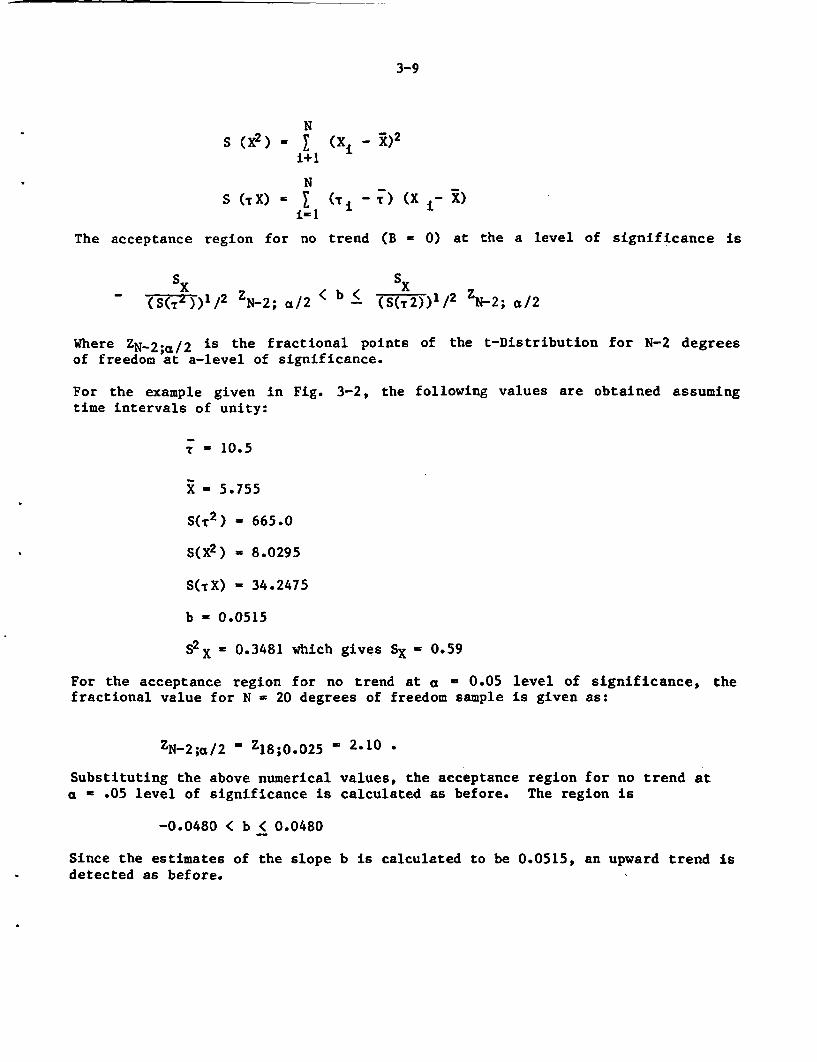
3-9
NS (x2 ) = I
i+1
NS (c X) - I
i I
(X i - x)2
(T i - T ) (X i- X)
The acceptance region for no trend (B = 0) at the a level of significance is
SX S.( S(r2) 1/2 ZN-2; a/
2 < b <(S(T
Where ZN-2;1/2 is the fractional pointsof freedom at a-level of significance.
For the example given in Fig. 3-2, thetime intervals of unity:
5)1/2 ZN-2; a/2
of the t-Distribution for N-2 degrees
following values are obtained assuming
T - 10.5
X= 5.755
S(T 2 ) - 665.0
S(X2 ) - 8.0295
S(TX) - 34.2475
b - 0.0515
S2X = 0.3481 which gives SX - 0.59
For the acceptance region for no trend at a - 0.05fractional value for N - 20 degrees of freedom sample
level of significance, theis given as:
ZN-2;a/2 - Z18 ;0 .025 - 2.10 .
Substituting the above numerical values, the acceptance region for no trend ata - .05 level of significance is calculated as before. The region is
-0.0480 < b < 0.0480
Since the estimates of the slope b is calculated to be 0.0515, an upward trend isdetected as before.
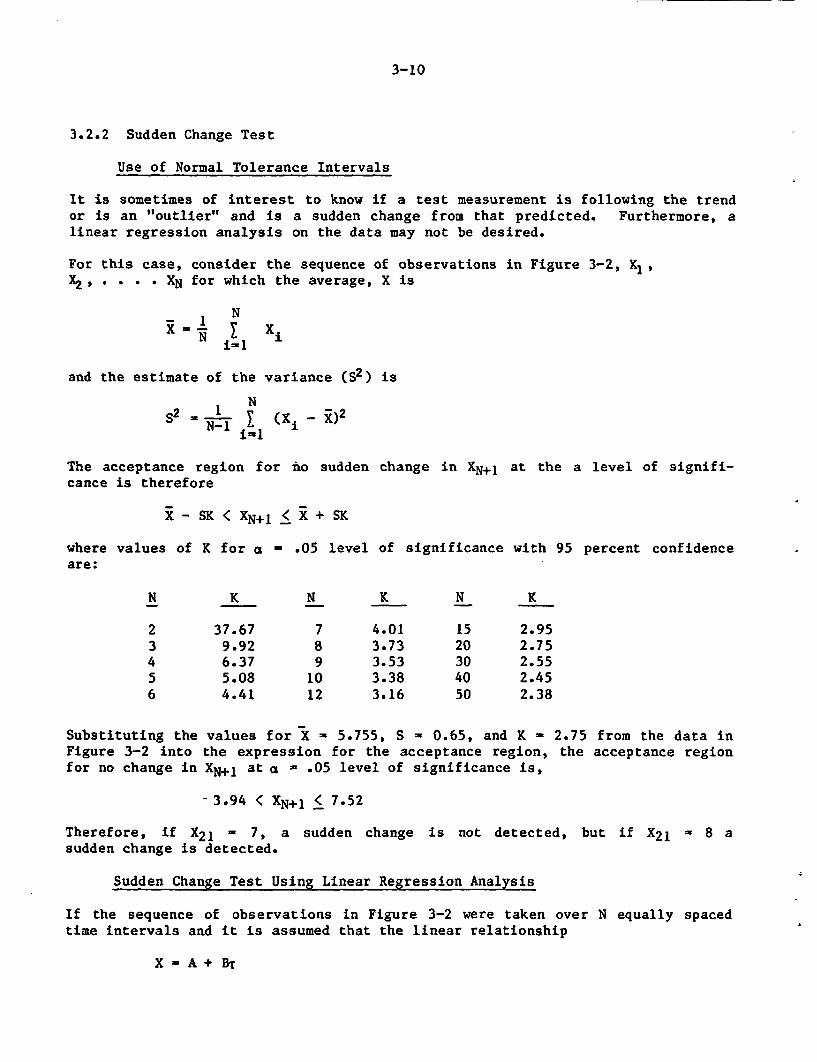
3-10
3.2.2 Sudden Change Test
Use of Normal Tolerance Intervals
It is sometimes of interest to know if a test measurement is following the trendor is an "outlier" and is a sudden change from that predicted. Furthermore, alinear regression analysis on the data may not be desired.
For this case, consider the sequence of observations in Figure 3-2, X1,X2, . . . XN for which the average, X is
N-X 1 I Xi
i- i
and the estimate of the variance (S2) is
NS2 1 (Xi-X)2
ill
The acceptance region for no sudden change in XN+j at the a level of signifi-cance is therefore
X - SK < XN+1 < X + SK
where values of K for a = .05 level of significance with 95 percent confidenceare:
N K N K N K
2 37.67 7 4.01 15 2.953 9.92 8 3.73 20 2.754 6.37 9 3.53 30 2.555 5.08 10 3.38 40 2.456 4.41 12 3.16 50 2.38
Substituting the values for X - 5.755, S - 0.65, and K - 2.75 from the data inFigure 3-2 into the expression for the acceptance region, the acceptance regionfor no change in XN+1 at a - .05 level of significance is,
- 3.94 < XN+l < 7.52
Therefore, if X21 - 7, a sudden change is not detected, but if X21 - 8 asudden change is detected.
Sudden Change Test Using Linear Regression Analysis
If the sequence of observations in Figure 3-2 were taken over N equally spacedtime intervals and it is assumed that the linear relationship
X - A + BT
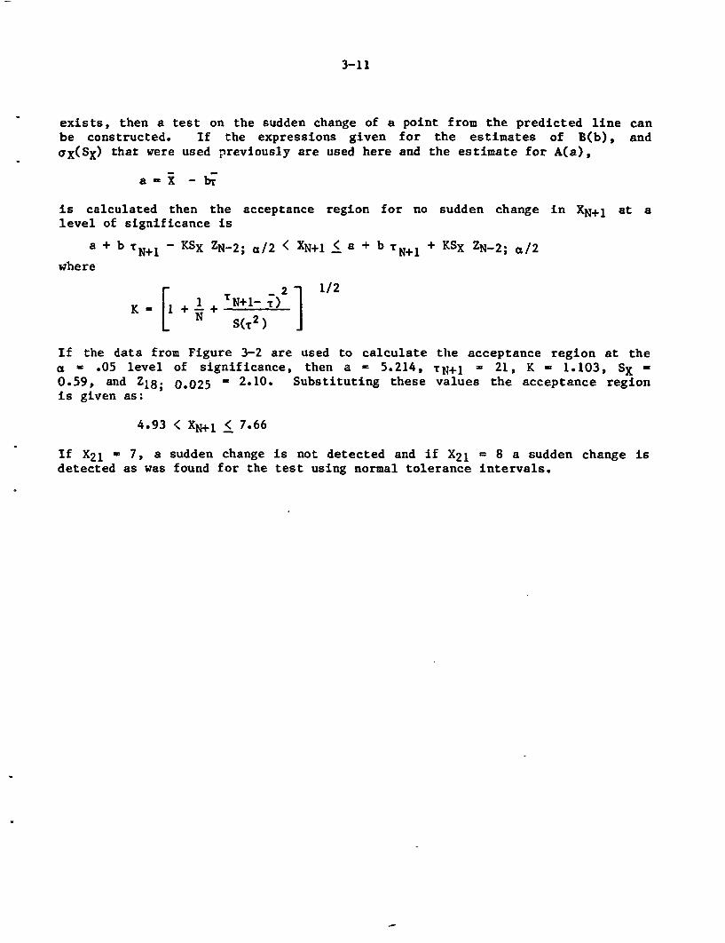
3-11
exists, then a test on the sudden change of a point from the predicted line canbe constructed. If the expressions given for the estimates of B(b), andaX(SX) that were used previously are used here and the estimate for A(a),
a - X - br
is calculated then the acceptance region for no sudden change in XN+1 at alevel of significance is
a + b TN+1 K KSX ZN-2; a/2 < XN+1 < a + b TN+l + KSX ZN-2; a/2
where
[ 1 + VN+J -2 1/2
K T NlrN S(Tr2) j
If the data from Figure 3-2 are used to calculate the acceptance region at thea - .05 level of significance, then a - 5.214, TN+j - 21, K - 1.103, SX -
0-59, and Z18; 0.025 - 2.10. Substituting these values the acceptance regionis given as:
4.93 < X+j < 7.66
If X21 - 7, a sudden change is not detected and if X21 = 8 a sudden change isdetected as was found for the test using normal tolerance intervals.
4-1
4. OTHER ELEMENTS AFFECTING THE MAINTENANCE PROGRAMS
In addition to the performance evaluation and actual maintenance activities, thedevelopment of a good maintenance program (preventive or corrective) requiresseveral other considerations. These include a good planning and management pro-gram, effects of human interaction, environmental and operational factors, testequipment and spare parts availability, and a quality assurance program with pro-per documentation. Each of these factors, although not essential, plays a majorrole in developing an effective maintenance program. More over, each of them isapproached very differently by utilities. A general discussion on each subjectis provided in this Section.
EPRI studies (8-9) provided excellent guidance for developing preventive mainte-nance programs which can play an effective and essential role in minimizingequipment failure and enhancing plant safety and availability. Other factorsaffecting the overall maintenance program are the existing preventative mainte-nance and surveillance programs, mandatory maintenance activities, regulatory andlicensing requirements, plant monitoring instrumentation and designs, and theelectricity rates. The Phase I study within the NPAR scope identified the majorsources of motor failures experienced in nuclear power plants, and identified thefunctional indicators which can be measured and monitored to mitigate the mostfrequent failures. In the preceding sections, all of the techniques and proce-dures available to test or evaluate these functional indicators were discussed.This section describes other elements involving administration and cost aspectswhich must also be considered in developing an effective motor maintenance pro-gram.
4.1 Planning and Management
4.1.1 Budget and Scheduling
Managing the total maintenance budget and planning the different maintenanceschedules in a power plant are interrelated activities. The total maintenancebudget spent in a nuclear facility covers the two separate activities, correctivemaintenance and preventive maintenance (PM). The latter can include both manda-tory and discretionary programs. Mandatory programs are those required by oper-ating experience, vendor warranty, government regulation or other safety regula-tions. Discretionary programs are performed at the plant operators discretionbecause benefits resulted from them may override the cost. It is typical thatthe cost for corrective maintenance takes a larger proportion of the total budgetthan the preventive. Since these two activities are strongly related, an effec-tive preventive maintenance program (which might require a larger share of thebudget) could significantly reduce the corrective costs. This kind of programmanagement may better achieve safety goals, as well as improve the availabilityof power generation related equipment. Since nuclear facilities are required tomaintain the above two goals, preventive maintenance is considered to be an evenmore important program.
Scheduling of PM activities requires a good planning effort by the management/supervisory team, including scheduling of the performance evaluation and mainte-nance activities illustrated in Figure 1-1. This depends on the availability of
4-2
maintenance personnel, test equipment, maintenance tools, the equipment (i.e.motor) under maintenance, and many other plant specific factors. Considerationof all of these variables in the development of an effective maintenance scheduleis extremely complex and, therefore a computerized system is essential.
4.1.2 Cost-Benefit Considerations
Optimization of the preventive maintenance interval (which includes conditionmonitoring) is easy to do in theory, but difficult to implement because of thelack of reliable data. Computer-based time dependent unavailability analysis(25,26) can be performed for planning the maintenance intervals, taking intoaccount the plant risk factors. In this section the principles of a cost-benefitanalysis for optimizing the maintenance interval will be discussed using a simpleapproach and giving an example of the analysis.
Principles of Cost-Benefit Analysis
To perform a cost benefit analysis for optimizing the PM interval (27) it isnecessary to know the failure rates of the equipment in question and the costsassociated with the PM and the repair costs (labor plus parts and services).Then the annual costs for repairing the equipment and for the PM can be compared.
The effect of periodic maintenance or monitoring on equipment can be evaluated ifit is assumed that the equipment is restored to a "good as new condition" eachtime. The success in achieving this goal can be enhanced by performing conditionmonitoring (CM) in addition to the PM, which is commonly recommended by thevendor and ordinarily performed by maintenance personnel. The more parametersthat can be evaluated to provide an accurate picture of the health of the equip-ment, the greater the probability of preventing an unexpected common-cause fail-ure of a critical component. In fact, if regular CM is performed, then PM can beperformed on condition rather than on a fixed schedule. This is the basis of aReliability Centered Maintenance (RCM) program as used in the aerospace industry(28).
The failure rates for equipment are generally described by the classic bathtubcurve which shows high instantaneous failure rates for very new and very oldequipment, and a lower, random instantaneous failure rate in between theseperiods (29). The failure rates for equipment can be determined by collectingfailure rate data as a function of time and finding a model to describe thedata, so that predictions can be made. Below is a discussion of failure ratemodels taken from several sources (30,31) that are applicable to equipment in anuclear plant.
The instantaneous failure rate, X(t) is defined as
dNf(t) 1B(t) d(t) xNv
4-3
where:
Nf(t) - number of devices failing
NS(t) - number of devices surviving
No = total number of devices under test
Nf(t) + Ns(t) - No
The probability density function, f(t) for the failure rate can be expressed by
dNf(t) If(t) = dt N
0
The Weibull Distribution is a very general failure distribution which applies toa large number of diverse situations. The failure rate can be expressed by
a-lA(t) d (-) for t > X
where:
a - Weibull slope (shape parameter) which is a direct function of the uniformityof the item. The larger the slope, the greater the uniformity. For a < 1,)(t) is decreasing. For a = 1, X(t) is constant. For a > 1, A(t) isincreasing.
-' location parameter (determined from test data)
6 data dispersion parameter (determined from test data).
The probability density function, f(t) for the normal distribution of failurescan be expressed by
1 ~ (t-t m)2f W - exp (- )
a / 2v 2a2
where:
a standard deviation (evaluated from test data)
t - age of equipment
tm W mean wearout life (evaluated from test data)
The gamma distribution of instantaneous failure rates is appropriate for equip-ment subjected to an environment of repetitive and random shocks generatedaccording to the Poisson distribution. In other words, when the rate of aging israndom, the gamma distribution is appropriate. The probability density functionfor the gamma distribution, f(t), can be expressed by
4-4
f(t) 1 I (,b) exp (--s )
where:
r - gamma function
a,b - experimentally determined constants
Also, the instantaneous failure rate, g(t) can be expressed by
)L(t) b(a+l)
The instantaneous failure rate for the Poisson Distribution of failures is forphenomena for which the average probability of an event is constant and indepen-dent of previous events. The failure rate is assumed constant in time so that
X(t) X
Since the Poisson Distribution assumes a time independent failure rate, it is notimportant in the type of cost benefit analysis discussed in this section.
Application of a Cost-Benefit Analysis
A cost-benefit analysis for optimizing the maintenance (including CM) intervalfor a motor operated valve can serve as an example of how such an analysis can beperformed. It is assumed that there is sufficient redundancy and diversity ofthe MOVs to make the probability of a forced outage so low as to be insignifi-cant.
The cost for PM of a MOV will include the labor for performing visual inspection,meggering and measuring the polarization index. These costs are summarized inTable 4-1.
The optimum PM schedule can be determined by comparing the costs for performingPM with the costs of repairing the equipment, assuming a failure rate. Whilepublished literature on equipment failure rates is rare, Sheliga (32) collecteddata at Cleveland Electric Illuminating Company on 10,000 failures over severalyears for 23 categories of electrical equipment. From this compilation, it wasfound that the failure rate for the equipment could be expressed by
x - b x P2
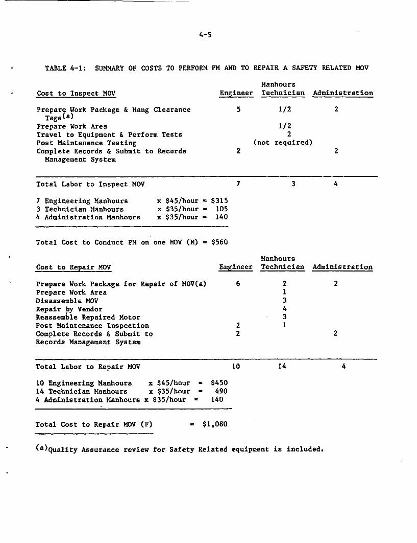
4-5
TABLE 4-1: SUMMARY OF COSTS TO PERFORM PM AND TO REPAIR A SAFETY RELATED MOV
- Cost to Inspect MOVManhours
Engineer Technician Administration
Prepare Work Package & Hang ClearanceTags(a)
Prepare Work AreaTravel to Equipment & Perform TestsPost Maintenance TestingComplete Records & Submit to RecordsManagement System
5 1/2
1/22
(not required)
2
22
Total Labor to Inspect MOV 7 3 4
7 Engineering Manhours3 Technician Manhours4 Administration Manhours
x $45/hourx $35/hourx $35/hour
= $315= 105= 140
Total Cost to Conduct PM on one MOV (M) = $560
ManhoursEngineer Technician AdministrationCost to Repair MOV
Prepare Work Package for Repair of MOV(a)Prepare Work AreaDisassemble NOVRepair by VendorReassemble Repaired MotorPost Maintenance InspectionComplete Records & Submit toRecords Management System
6
22
213431
2
2
Total Labor to Repair MOV 10 14 4
10 Engineering Manhours14 Technician Manhours4 Administration Manhours
x $45/hourx $35/hour
x $35/hour
a $450- 490
= 140
Total Cost to Repair MOV (F) - $1,080
(a)Quality Assurance review for Safety Related equipment is included.
4-6
where:
Xb = a failure rate (in events per hour) when the maintenance interval isone year
P - the maintenance period in years
2 - an exponent that is an acceptable approximation for the data atCleveland Electric Illuminating Company.
The annual repair cost (ARC) of the equipment can be expressed by
ARC - F x X x 8760
where:
F - cost of an equipment failure
8760 - number of hours in a year
The annual cost of PM is
ARCpM = M/P
where:
ARCpM = annual cost of performing PM on the equipment
M - cost of performing PM on one equipment
P - the maintenance interval in years
The total annual cost of maintaining the equipment (TC) is
TC = ARC + ARCpM
The optimum PM schedule is determined by plotting ARC, ARCpM and TC with themaintenance period and observing the PM interval where the minimum TC is located.The annual cost to inspect the MOV (ARCpM), the annual cost to repair the MOV(ARC) and the annual total cost (TC) are calculated in Table 4-1. The data usedin the Table is based on discussions with personnel in the electrical maintenancedepartment of a utility with a pressurized water reactor that entered into com-mercial operation approximately one year ago. The repair costs are representa-tive of the most frequently occurring corrective maintenance for MOVs. Becauseof the generality of the assumptions in this example analysis the results areuseful only for illustrating how to perform the analysis.
The failure rates for MOVs are obtained from the In-Plant Reliability Data Study(IPRDS) and have been summarized by Greenstreet et al. (B2). For motor drivenglobe valves, the failure rates were 48.0 x 10⁻⁶ per hour for one plant and39.1 x 10-6 per hour for a second plant.
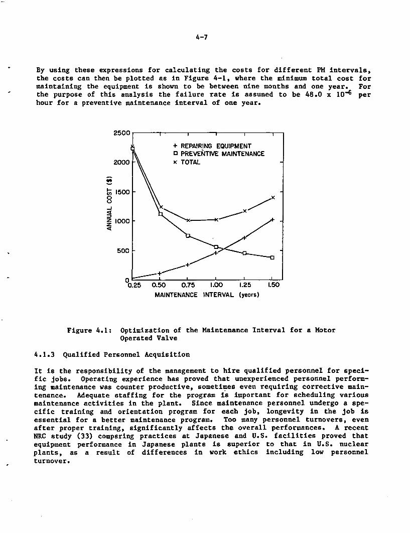
4-7
By using these expressions for calculating the costs for different PM intervals,the costs can then be plotted as in Figure 4-1, where the minimum total cost formaintaining the equipment is shown to be between nine months and one year. Forthe purpose of this analysis the failure rate is assumed to be 48.0 x 10⁻⁶ perhour for a preventive maintenance interval of one year.
2500
2000
c'- 1500
500
0.25 0.50 0.75 1.00 1.25
MAINTENANCE INTERVAL (years)
1.50
Figure 4.1: Optimization of the Maintenance Interval for a MotorOperated Valve
4.1.3 Qualified Personnel Acquisition
It is the responsibility of the management to hire qualified personnel for speci-fic jobs. Operating experience has proved that unexperienced personnel perform-ing maintenance was counter productive, sometimes even requiring corrective main-tenance. Adequate staffing for the program is important for scheduling variousmaintenance activities in the plant. Since maintenance personnel undergo a spe-cific training and orientation program for each job, longevity in the job isessential for a better maintenance program. Too many personnel turnovers, evenafter proper training, significantly affects the overall performances. A recentNRC study (33) comparing practices at Japanese and U.S. facilities proved thatequipment performance in Japanese plants is superior to that in U.S. nuclearplants, as a result of differences in work ethics including low personnelturnover.
4-8
4.2 Human Factors
4.2.1 Personnel Training and Skills
Maintenance performed by unskilled personnel can be disastrous. Therefore it isimportant that job task analysis be conducted so that the necessary skills foreach position are identified, and that training is implemented to teach theseskills. Training should not be a one time event, but must be periodicallyrefreshed and improved upon. INPO, NRC, and the nuclear utilities are expendingconsiderable resources on improving NPP training.
4.2.2 Personnel Protection and Safety
Unlike fossil fuel power stations, nuclear power plant designs have motors inharsher environments, specifically, high radiation areas (inside containment andother fuel storages areas), where personnel exposure should be kept to a minimum.Motors located there must be monitored and maintained while minimizing personnelexposure to radiation. If needed, sophisticated monitoring devices, includingprobes mounted on the equipment (i.e. accelerometers, RTDs, transducers, etc.)can be provided to monitor its performance outside the high radiation area at theswitchgear, MCC, or control room. Since maintenance, personal safety, and pro-tection are specific for the particular equipment, all the precautionary measuresshould be included in its maintenance procedure. Notices and information on theparticular equipment itself relative to human safety are considered to be a goodpractice as well.
4.2.3 Human Reliability
The Phase I study verified that electric motors do degrade with age and a numberof performance measures were identified which may indicate the onset of motordegradation. In this study, the overall maintenance program was separated intotwo broad areas of activity aimed at mitigating the potential effects of equip-ment aging: (1) Performance Evaluation, and (2) Equipment Maintenance. Equip-ment maintenance involves actually maintaining the condition of the equipment,while performance evaluation involves only those activities undertaken to monitorsigns of degradation due to aging. This section discusses the human factorswhich may be of importance in Performance Evaluation.
Periodic Testing
Periodic testing involves measuring performance indicators of a motor and testequipment to monitor those indicators. For example, to test phase-to-ground insu-lation on a motor, a maintenance technician would bring a shunt box to the motor,make certain connections to the motor terminals and record the resistance whileoperating the motor. Another example would be the removal of a part from a motorso that it could be brought to a laboratory for testing. These activities typi-cally are planned and scheduled in advance, involve the use of written proce-dures, and are tasks for which training has been extensive.
The effectiveness of periodic testing is highly dependent on (1) the skill of thetechnician conducting the tests, and (2) the accuracy of the calibration of testequipment by the I&C staff. These two activities should be examined separately
4-9
since a failure of either task could cause the results of the test to bemisleading. (It must be noted that the actual conduct of the test may serve asfeedback on the calibration; however, this mode of feedback cannot be relied on.)
These two areas of human activity should be examined using task analysis techni-ques to identify aspects of human performance which may be affected by perfor-mance shaping factors (PSFs). As an illustration, the testing task describedabove may be very dependent on the level of training given to the maintenancetechnician. If a certain application of periodic testing involves motors thatrequire unique procedures compared to most other motors tested, a measure ofwhether training as a PSF significantly affects the likelihood of technicianerror can be ascertained from examining the training curriculum. If the uniqueprocedure is not covered explicitly in the course material, then some other meansof assuring adequate performance must be present (e.g. extensive explanation inthe tasks procedures.) Task analysis allows for identification of these types ofPSFs.
After a general task analysis has been undertaken, a logic model of the generaltasks can be constructed. These models are very similar to an event tree and inthe case of the particular testing task involved may be called a "MaintenanceTechnician Action Tree." It can be used to identify the most sensitive tasksfrom the standpoint of failure in conducting the overall test, and is done muchthe same way as the minimum cut-set runs for a PRA plant model.
Continuous Monitoring
Continuous monitoring involves reading or observing built-in performance measureindicators (i.e. instrumentation) at the location of the motor, motor controlcenters, or control room. For example, if an operator is checking the currentdraw on a particular motor he would walk to the location of the motor controlcenter or switchgear and record his observation of the ammeter. While theseactivities are generally planned and scheduled, a certain amount of informal con-tinuous monitoring also takes place. It would be useful to examine means ofstrengthening the informal level of continuous monitoring as well as assuring thequality of scheduled and planned activities.
Formal observations of equipment instrumentation normally are done according to aschedule, with procedures and checklists. In terms of these tasks, it can beassumed that training and procedures will be principal PSFs. Task analysis canidentify those factors that are important in correctly performing these tasks andthen develop review criteria for training curricular and procedures reflectingthose factors.
The informal level of continuous monitoring occurs when an operator or technicianis on other duties and comes close enough to a motor to observe its instrumenta-tion. Much of the time, the individual will not have all necessaryreferences tonote any small deviations from normal, but will be able to identify larger devia-tions, especially if indicators are appropriately marked with alert or red linevalues. The next step will be to notify the cognizant supervisor or otherwisecommunicate the information. Because of the small deviations which may charac-terize advanced signs of aging, these may remain unreported. As a consequence,
4-10
there are two principal areas for examination in the realm of continuousmonitoring on an informal level: (1) the success or failure of individuals tonotice aging-related deviations from normal readings on built-in equipmentinstrumentation, and (2) the means by which these reading are reported, receivedand addressed in the overall plant organization.
The first area can be examined by task analysis. Some measures might be consi-dered, like indicating safe operating ranges on meter faces or, for equipmentthat varies depending on plant operating conditions, posting near the instrumen-tation normal readings and acceptable deviations and regularly updating them.However, making an actual assessment of this area will require conducting a taskanalysis. The second area will require some degree of organizational analysis toidentify optimal means of encouraging reports of deviant readings as expedientlyas possible.
Surveillance Testing
It would be possible to examine means of improving surveillance testing to pro-vide information about the performance of motors. Generalized task analyses oftech spec performance monitoring tasks involving motors could be undertaken tofind opportunities for gathering data on aging performance indicators and totransfer those data to the proper organizational sub-unit (e.g., maintenance,I&C, reliability program, etc.)
Inspection
Inspection can be defined as any activity which involves observation of perfor-mance measures which are not given by remote or built-in instrumentation, forexample, the physical condition or appearance of motors, or water leaks in thearea. These inspections are performed on a planned and scheduled basis. How-ever, any operator can recognize significant deviations from an acceptable indi-cators if they are sensitive to them. Operators action models could be developedfor the planned and scheduled inspection activities and also for informal obser-vations during normal operation. In addition, informal inspection aids such asposting acceptable performance measures and deviations could be considered.
General Discussion
In addition to identifying the proper performance measures and developing reason-able means for assuring that the appropriate data will be collected, the finaluse and disposition of the data collected is clearly important. There are manyhuman factors involved in data collection and analysis. Another area whichshould be systematically examined involves how the results of analyses are usedto obtain optimal responses. It is likely that many of the indicators being mon-itored will be relatively minor, or are cumulative in nature so that an inductiveapproach should be used to decide on actions to be undertaken. In many cases theoptimal response may be that no equipment maintenance actions will be taken, butrather increased performance measurements. It is important to consider humanfactors that affect the likelihood of an optimal response.
4-11
4.3 Environmental and Operational Factors
4.3.1 Environmental Conditions
The age of the motor, coupled with consideration of the environmental and opera-tional characteristic, can help determine the frequency of maintenance. Motorsin a harsh environment but not critical to safety or plant availability, are theleast important and will have longer maintenance intervals, while those motors inthe same environment and critical to the plant need to be maintained more fre-quently. As the age of the motor increases, its components degrade faster andhence, the maintenance intervals should be shortened until it is established thatthe required reliability is achieved. On the contrary, if a particular motorexhibits a higher reliability, the interval may be increased.
Good housekeeping and good operational procedures can increase the life of theequipment. Most motors in the plant are designed to withstand the designatedenvironment and operating modes for their lifetime. However, in many cases,abusive operation and poor maintenance can accelerate the degradation process.
4.3.2 Operating Condition
Operating schedules of motors in the plant also dictate the maintenance sche-dule. For example, safety system motors that remain in standby during plantoperation are maintained while not operating. Non-safety large motors (i.e. RCPand Recirculation Pump Motors) which are located inside the containment and areimportant to plant availability, are scheduled for maintenance during a plantoutage. An optimized schedule should compromise between the need for keepingmotors in operational readiness and keeping the plant operating while performingthe evaluations.
4.4 Test Equipment and Spare Parts
4.4.1 Test Equipment, Tools and Procedures
Maintenance in nuclear power plants is constantly being upgraded with the adventof more sophisticated test equipment and tools. The test equipment industry hasbeen facing the challenge to monitor and to maintain nuclear components in func-tional condition inside the containment. For motors, the industry developed manytest devices for the age-related degradations of components as well as for theiroperability. The size of these devices has been decreasing with the use ofmicroprocessors for performing in situ test on the component or at the controlcenter.
The operating experience of motor performance in nuclear facilities shows thatthe bearings and insulating systems are the significant contributors to motorfailures (7). Abnormal vibration measurements typically are indicative of eitherbearing or stator core degradation. Large motors are often equipped with built-in vibration transducers at the bearing housings for continuous monitoring. Dur-ing the last decade, portable vibration monitoring units with Fast Fourier Trans-form (FFT) capability became available for testing the velocity response of smal-ler motors. The frequency content of the response is used to diagnose the root-cause of motor component degradations with age.
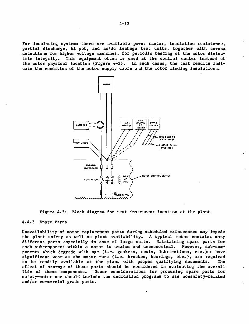
4-12
For insulating systems there are available power factor, insulation resistance,partial discharge, hi pot, and ac/dc leakage test units, together with coronadetections for higher voltage machines, for periodic testing of the motor dielec-tric integrity. This equipment often is used at the control center instead ofthe motor physical location (Figure 4-2). In such cases, the test results indi-cate the condition of the motor supply cable and the motor winding insulations.
THERMALOVERLOADS
CONTACTOR
CONTROL CENTER
Figure 4.2: Block diagram for test instrument location at the plant
4.4.2 Spare Parts
Unavailability of motor replacement parts during scheduled maintenance may impedethe plant safety as well as plant availability. A typical motor contains manydifferent parts especially in case of large units. Maintaining spare parts foreach subcomponent within a motor is unwise and uneconomical. However, sub-com-ponents which degrade with age (i.e. gaskets, seals, lubrications, etc.)or havesignificant wear as the motor runs (i.e. brushes, bearings, etc.), are requiredto be readily available at the plant with proper qualifying documents. Theeffect of storage of those parts should be considered in evaluating the overalllife of these components. Other considerations for procuring spare parts forsafety-motor use should include the dedication programs to use nonsafety-relatedand/or commercial grade parts.
4-13
4.4.3 Vendor Assistance/Manuals
Each motor from the manufacturer is furnished with instructions for installationand operation of the machine. These manuals generally describe the standard war-rantee policy, handling and storage instructions, installation procedures, elec-trical connections, insulatioti resistance characteristics, operational character-istics, maintenance instructions for all subcomponents, renewal parts list, line-by-line instructions for assembling and disassembling the motor, and discussionsof any special features in the machine. They also include common problems andremedies that are useful to keep the motor operating. Therefore, it is importantthat the maintenance crew should become familiar with the machine prior to per-forming any diagnosis on the motors. These manuals should be stored either inthe qualification document for the particular motor or at the machine locationfor easy reference during the maintenance. Often manuals are updated or mainte-nance bulletins are issued by the manufacturer, with whom periodic contact shouldbe maintained to ensure that the utility has the latest technical information andmanuals.
Rarely, a case comes up where the abnormal motor performance is beyond the scopeof the instruction manuals or the maintenance engineer. In such events, promptvendor assistance for bringing the motor to operation should be available.
Unless proven otherwise, it is a good practice to utilize the replacement partsand grease or oil recommended in the manufacturer's instruction manuals.
4.5 Quality Assurance and Documentation
4.5.1 Quality Assurance
In operating a nuclear power plant in United States, the utility company isrequired to adopt a detailed quality assurance (QA) program, as required by1OCFR50, App. B, for all activities affecting the safety-related structures, Sys-tems, and components. These activities include designing, purchasing, fabricat-ing, handling, shipping, storing, cleaning, erecting, installing, inspecting,testing, operating, maintaining, repairing, refueling and modifying. Qualityassurance comprises all those planned and systematic actions necessary to provideadequate confidence that a structure, system or component will perform satisfac-torily in service. It also includes quality control (QC) which comprises thoseassurance actions related to the physical characteristics of a material, struc-ture, component, or system.
All maintenance procedures and activities, therefore, are required to have aquality assurance program, when used on safety related motors. Test equipmentprocedures, use of spare parts, and other related activities should contain aquality control mechanism to ensure the functional readiness of the equipment.Some aspects of the QA/QC Program are often applied to other important motors inthe plant.
4.5.2 Technical Specifications
Each motor performing a safety function in a nuclear power plant is subjected tothe technical specification (tech spec) requirements for its system defining the
4-14
allowed outage times (AOTs) and surveillance test intervals (STIs). Typically,tech spec requirements are applied when a motor fails to deliver its intendedfunction. These activities are described under surveillance tests in Appendix B.
Since the objective of a good preventive maintenance is related to that of thetech spec activities involving safety motors, the scheduling of tests and mainte-nance should be chosen to be commensurate with the tech spec intervals. Itshould be noted that there are no specific tech spec requirements for motorsalone, however, this requirement for motor operated valves and motor driven pumpsalso include the driver.
4.5.3 Documentation
One of the differences between operating a nuclear facility and a non-nuclearfacility is maintaining a documentation file on each safety-related component.Because of the volume of information, many utilities prefer a computerized handl-ing system to afford easy access and control on the data. The data base includesall pertinent equipment records, such as name plate and manufacturing data,qualification documents, instruction manual, and other design information.Inspection and maintenance records, checklists and their schedules also are partof the system for training or future reference.
5-1
5. REVIEW OF CURRENT MAINTENANCE PRACTICES IN INDUSTRY
Prior to assessing a maintenance procedure for motors, it is important to gain anunderstanding of the current practices in motor maintenance in nuclear plants.Surveying all nuclear facilities for this information is beyond the scope of thisstudy. However, a representative sample of maintenance and surveillance programswere reviewed by Sugarman and Sheets (34) and are described here. Section 5.1gives the details about the surveyed plants, Section 5.2 includes the surveyresults, and 5.3 discusses the current trends in industry in evaluating the motorperformances.
Although no definitive condition monitoring program exists in any of theseplants, the trend in Americah utilities is to:
a. Establish computer data bases which contain files for maintenance histories,seismic and environmental qualification, replacement parts, etc..
b. Perform "Condition Monitoring" on equipment which previously was only main-tained.
c. Use increasingly sophisticated techniques for obtaining physical data thatcan diagnose anomalies associated with equipment failures.
The reason for these trends is the concern by the Nuclear Regulatory Commissionand the utility industry for achieving a greater assurance of the reliability ofsafety related and important-to-safety equipment as well as the pressure on theutilities to improve the availability of their plants. Section 5.4 summarizesindustry standards applicable to motors. Section 5.5 discusses the EPRI Survey[Motor Maintenance/Surveillance Survey (MM/SS)] on motors. The last section 5.6concludes the results from the four plant surveys.
5.1 Description of Surveyed Plants
Four stations (two PWRs and two BWRs) were included in the survey on motor main-tenance procedures. The A-PWR station includes two units which began commercialoperation within the last five years. The construction permits were issued in1973. This station has well developed preventive maintenance (PM), correctivemaintenance and surveillance programs.
The B-PWR station includes two units which began commercial operation in last tenyears. This station has a well developed, computerized PM program in which workorders are automatically displayed on a screen at the time they are to be per-formed, and are transmitted to the Maintenance Department which attaches a proce-dure to them before they are taken into the field. The Work Planning and Track-ing System Department is developing a trending program for the PM data.
The C-BWR station began commercial operation in 1984. This station has a compre-hensive computerized PM program and a well developed corrective maintenance pro-gram. The PM program has provisions for the required plant modes, special plantconditions per the technical specifications, the desired start and completiondate, critical completion date and historical schedular data in addition to theinformation commonly provided (i.e. description and identification of the compo-nent, task numbers and the task description).
5-2
The D-BWR station includes two units which began commercial operation in theearly 1970's. The station is developing a PM program, but at present relies onlyon its surveillance and corrective maintenance programs.
According to their recent Systematic Assessment of Licensee Performance (SALP)ratings, these plants have had average rating on maintenance programs and hence,could be considered as typical programs, neither exemplary nor in need of majorimprovement.
5.2 Summary of Survey Results
The maintenance and surveillance requirements for several different types ofmotors and motor operators are summarized in this section. Only those tests areincluded which could provide quantitative data for motors and which are suitablefor trending. For example, maintenance procedures for adjusting torque/limitswitches, inspecting the oil level in the gear case, overhauling motors, cleaningcomponents, changing seals, are omitted, as are the procedures for the mainte-nance and surveillance of driven equipment, such as pumps, valves and fans. Someof the procedures for the driven equipment, however, are included for trendingthe vibration test results which are important for continuous duty motors.
While most of the procedures are for small motors, the same procedures are usedon high voltage motors (e.g. those greater than 4.16 kV).
Meggering of insulation resistance is performed by the plants. Some plantsrequire that the phase-to-ground and phase-to-phase insulation resistance bemeasured, while others require only a phase-to-ground insulation resistance test.Since the phases in most electric motors are electrically connected to each otherinternally it is not clear how the phase-to-phase insulation resistance can bemeasured unless the phases are determinated. Some of the plants correct the meg-ger values for the resistance at 40:C, according to the requirements in IEEEStandard 43. Some of the procedures specify that the reading should be takenafter waiting one minute while other procedures have no such instructions. Theacceptance criteria for the insulation resistance varies; some plants require theminimum insulation resistance be greater than a fixed number (e.g. 1.5 megohms)while other plants use a formula provided in IEEE Standard 43 to establish theminimum acceptable level.
Some plants perform a polarization index (PI) test and at one plant the test isperformed at two pairs of durations - 10 minutes/i minute and 60 seconds/30seconds intervals. It was required by one plant that the ambient temperature be< 40C before the PI be taken. The effect of temperature on the PI is not wellknown, but there may be some effects because the leakage current is the sum ofseveral different components, each making different contributions to the totalabsorption current over time and having different temperature coefficients. Theacceptance criteria for PI varies from 1.4 to 2, with no reference made to themotor insulation class. The IEEE standard 43 recommends minimum PIs of 1.5 (forClass A insulation), 2.0 (for Class B insulation) and 2.0 (for Class F insula-tion). None of the plant procedures reviewed indicated a recognition of the factthat even though the PI may be better than the specified value, the resistancereadings in the ratio may be so low that the acceptability of the test should bequestioned. On the other hand, low PI values may be the ratios of acceptablyhigh resistance readings.
5-3
The valve motor running current is measured by three of the utilities. Theacceptance criteria established by one of the utilities was a reading of < 125%of the nameplate current. This value is within the range of service factors (amultiplier for the permissible horsepower loading which may be carried underspecified conditions) recommended in NEMA Standard MG1-12.47 for General-PurposeAlternating-Current Motors.
The range of service factors in NEMA Standard MG1-12.47 for a four pole motor is1.15 (for a 1-1/2 to 125 H.P. motor) to 1.4 (for a 1/20 H.P. motor). MOV runningcurrent screening values are also being developed based on manufacturerrecommendations.
Other motor tests are:
a. Motor noise and vibrationb. Motor winding continuityc. Phase rotationd. Stroke timee. Leakage in valve pressurized with nitrogenf. Measurement of limit/torque switch actuation cycle, motor running current,
valve stem thrust with MOVATS.
The motor maintenance and surveillance procedure formats were compared to eval-uate the consistency among nuclear plants: the results are summarized in Table5-1. They showed that certain portions of the procedure, such as objective (orpurpose), references, prerequisites (or special tools or equipment), precautions,procedure (or instructions) and sign-offs were found in all cases. Most of theprocedures had tables of contents (or indices) and some had sections for accep-tance criteria, post-maintenance testing (or restoration) and records. The"Records" Section is generally a statement directing the maintenance personnel tocomplete certain data forms and forward them to the responsible supervisor.
The only surveillance test performed on MOVs is stroke time. The procedures forthe plants reviewed always provided acceptance criteria either on the data sheetsor by referring to the Technical Specifications, Safety Analysis Report (SAR) andNSSS Vendor Specifications. The surveillance tests did not always require thatthe test data be recorded but only a statement on the acceptability of the testresults (a yes or no response).
It is noteworthy that the data record requires that both the uncorrected and cor-rected resistance readings be entered and the acceptance criteria are provided inthe maintenance procedure.
The PM frequency on equipment in different systems may have different schedulesand tasks depending on their quality classification (e.g. safety related, notsafety related, important to plant availability) and their function. Table 5-2illustrates some test frequencies which are performed on rotating electricalequipment.
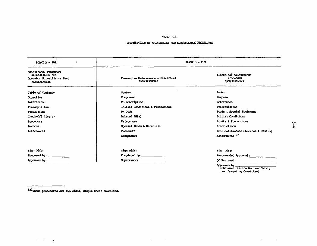
TALE 5-1
0WRGIZATIG4 OF MAINTENANCE AND SURVEILLANCE PROCEDURES
PLMT A - PW f PLANT B - PM
Maintenance ProcedureXXXXXXXXXXX and Electrical Maintenance
Operator Surveillance Test Preventive Maintenance - Electrical ProcedureYX mXXXXXXXXXX xxXXXXXXX
Table of Contents
Objective
References
Prerequisites
Precautions
Check-Off List(s)
Procedure
Records
Attachments
System
Ccmponent
PM Description
Initial Conditions & Precautions
iM Code
Related PM(s)
References
Special Tools S materials
Procedure
Acceptance
Sign Offs:
Completed by:
Supervisor:
Index
Purpose
References
Prerequisites
Tools & Special Equipment
Initial Conditions
Limits & Precautions
Instructions
Post Maintenance Checkout & Testing
Attachrwnts(a)
u'
Sign Offs:
Prepared by:
Approved by:
Sign Offss
Recom nded Approval:
ac Reviewed:_
Approved by:(Chairman Station Nuclear Safetyand Operating Committee)
(a)These procedures are two sided, single sheet formatted.
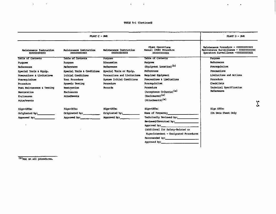
TABtE 5-1 (Contined)
PLANT C - BWh PLANT D - BWR
Plant Operations Maintenance Procedure - xxXxXXXXXMaintenance Instruction Maintenance Instruction Maintenance Instruction Manual (POM) Procedure Maintenance Surveillance - XXXXXXX
XXXXXXXEOXXX XXXXXI X XXXXXXXXXXXX xxxxxxxxxxx Operators Surveillance -XmXXXXXxxxx
Table of Contents Table of Contents Purpose Table of Contents Purpose
Purpose
References
Special Tools & Equip.
Precautions & Limitations
Prerequisites
Procedure
Post Maintenance & Testing
Restoration
Enclosures
Attachments
Sign-Offs:
Originated by:_
Approved by:
Purpose
References
Special Tools & Conditions
Initial Conditions
Test Procedure
Dynamic Testing
Restoration
Enclosures
Attachments
Discussion
References
Special Tools or Equip.
Precautions and Limitations
System Initial Conditions
Procedure
Records
Sign-Offs:
Originated by:
Approved by:
Purpose
(Equipsent Location) (b)
ReferencesRequired Equipment
Precautions a LimitationsPrerequisitesProcedure
(Acceptance Criteria)(a)
(Enclosures)(a)
(Attachnents)(a)
References
Prerequisites
Precautions
Limitations and Actions
Procedure
Checklists
Technical SpecificationReferences
'I
Sign-Offs:
Originated by:
Approved by:
Sign-Offs:
Nane of Preparerj
Technically Reviewed by:
Reviewed/Concurred by:
Approved by:
(Additional for Safety-Related or
Superintendent - Designated Procedures
Recomnended by:
Approved by:
Sign Offs:
(On Data Sheet Only
(b)Not on all procedures.
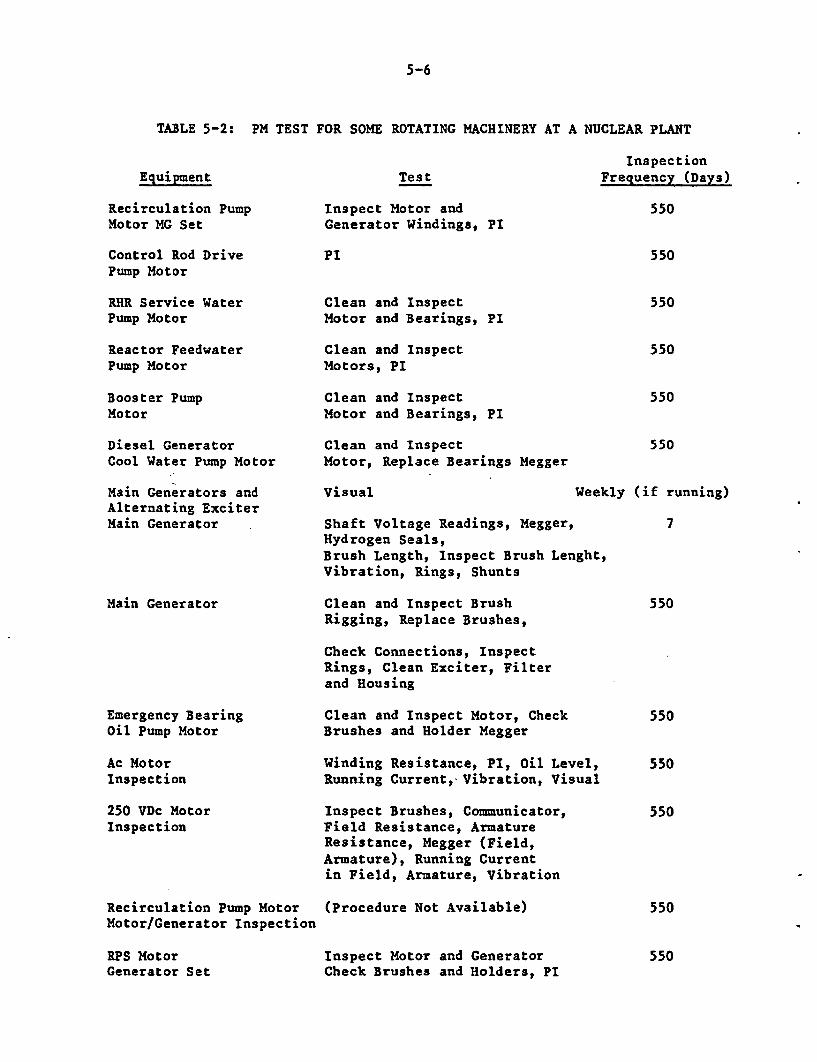
5-6
TABLE 5-2: PM TEST FOR SOME ROTATING MACHINERY AT A NUCLEAR PLANT
EquipmentInspection
Test Frequency (Days)
Recirculation PumpMotor MG Set
Control Rod DrivePump Motor
RHR Service WaterPump Motor
Inspect Motor andGenerator Windings, PI
PI
Clean and InspectMotor and Bearings, PI
550
550
550
Reactor FeedwaterPump Motor
Booster PumpMotor
Diesel GeneratorCool Water Pump Motor
Main Generators andAlternating ExciterMain Generator
Main Generator
Clean and InspectMotors, PI
Clean and InspectMotor and Bearings, PI
Clean and InspectMotor, Replace Bearings Megger
visual Week
Shaft Voltage Readings, Megger,Hydrogen Seals,Brush Length, Inspect Brush Lenght,Vibration, Rings, Shunts
Clean and Inspect BrushRigging, Replace Brushes,
550
550
550
ly (if running)
7
550
Check Connections, InspectRings, Clean Exciter, Filterand Housing
Emergency BearingOil Pump Motor
Clean and Inspect Motor, CheckBrushes and Holder Megger
Ac MotorInspection
Winding Resistance, PI, Oil Level,Running Current,- Vibration, Visual
250 VDc MotorInspection
Recirculation Pump MotorMotor/Generator Inspection
RPS MotorGenerator Set
Inspect Brushes, Communicator,Field Resistance, ArmatureResistance, Megger (Field,Armature), Running Currentin Field, Armature, Vibration
(Procedure Not Available)
Inspect Motor and GeneratorCheck Brushes and Holders, PI
550
550
550
550
550
5-7
5.3 Motor Performance Evaluation
In recent years, several utilities initiated computer based maintenance programs.One of the reasons for this is a concern for achieving a greater assurance of thereliability of safety related equipment, as well as the economic consideration ofimproved plant availability. A similar trend has been observed in the electricalequipment manufacturing industry where instrument systems have been developedthat can be programmed to conduct tests, gather data, compensate for temperatureand automatically measure important parameters. Portable test units also areavailable for instantaneous measurement of functional indicators without disas-sembly of equipment.
To improve reliability and performance and to reduce radiation exposure to per-sonnel, a remote monitoring program should be established to evaluate and diag-nose the testing data. This is typically referred to as condition monitoring ortrending of test data, using various functional indicators that are specificallychosen for the particular component. This data base is further augmented withadvanced information such as pattern recognition, statistical analysis, signatureanalysis, and human factors engineering. The result is a better understanding ofequipment performance and earlier warning of developing problems due to aging orservice wear, so that operations and maintenance planning is improved at an inci-pient stage.
A computer-based monitoring system is being implemented at Grand Gulf nuclearstation (35) that utilizes process and vibration instrumentation to monitor theoperational performance of 14 major pumps, 2 drive-turbines, 12 motors, 3 aircompressors, the high and low pressure turbines, and the generator-exciter. Thesystem monitors about 300 process variables and 200 vibration signals in eachunit. The overall program addresses a wide spectrum of issues that affect theevaluation of machinery performance during all phases of the total plant cycle,including pre-operation, start up, power operation, and outages.
Other U.S. utilities have established computerized data bases or are in the pro-cess of doing so. Northeast Utilities Company (NU) developed a computer-basedPreventive Maintenance Management System (PMMS) which provides equipment dataincluding make, model, serial number, bill of material data and space for con-ments (36). The database is in a central computer that is accessible by termi-nals throughout the NU generation and staff facilities. Another example of thetrend to computerization of nuclear plants is the Plant Information ManagementSystem (PIMS) which began development in 1983 by Pacific Gas and Electric Company(PG&E) in San Francisco. This system, which is nearing completion, will containthe following database:
equipmentcommitmentrecords management
. vendor listswarehouse stockequipment parts list
* bill of materialsrecurring tasks
5-8
* outage work breakdown structure* technical specification procedures
in-service inspection procedures* preventive maintenance procedures• surveillance test procedures.
The PIMS is installed on an IBM 4341 computer using the Multiple Virtual Storage(MVS) operating system and IBM compatible communication software, file struc-tures, and COBOL programming (37).
Some utilities have installed Personal Computer (PC) databases for weak-linkmaterials found in safety-related equipment. The data bases predict the amountof aging which has occurred in these materials for given environmental tempera-tures, and to keep track of changes made in the field to environmentally quali-fied equipment. With this system, one has a technical basis for extending thequalified lives of such equipment.
As licensees of the U.S. Nuclear Regulatory Commission, the utilities are requir-ed to perform regularly scheduled surveillance on certain safety-related instru-ments and equipment to insure that they are operating according to the technicalspecifications for the plant. There is some evidence to suggest that the strin-gent surveillance to which certain equipment is subjected results in improvedavailability (38). Nuclear utilities are beginning to recognize the advantagesof equipment surveillance and are beginning to focus attention on this area (39).Also, it should be noted that in some cases, such as diesel generators, stringentsurveillance (too many cold starts) can degrade equipment performance.
Nuclear utilities are currently searching for, and implementing more sophisti-cated surveillance techniques to improve equipment reliability. For example,some plants (e.g., Nine Mile Point #1, Oyster Creek Nuclear Generating Station),are obtaining signatures of the thrust and torque/limit switch actuation to diag-nose degradation in MOVs, using MOVATS system. Manufacturers of test equipmentare responding to the trend toward more sophisticated surveillance equipment.Some instrument companies are marketing an insulation analyzer for equipment suchas motors, cables, etc. which uses newly developed algorithms in conjunction withmicroprocessor control to automatically select test voltage, gather data and cal-culate the true insulation resistance after a short, ten-minute test. An impor-tant feature of this instrument is its ability to discriminate among the threedifferent components of the charging current (geometric capacitance current,absorption current, and conduction or leakage current (40). It is the conduction(or leakage) current which is generally sought in an insulation tests.
Surveillance tests to monitor the performance and mechanical operation of thevalve motor operator can provide other data through interrelated aspects of valvestem thrust signature analysis and limit/torque switch performance, and may beobtained with the HOVATS system or the system being developed by ORNL in itsphase 2 NPAR study on motor operated valves.
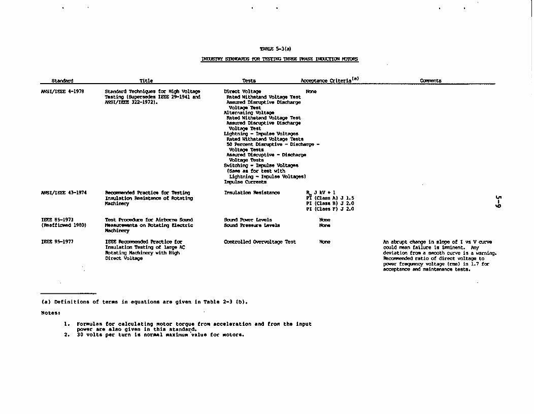
TWHE 5-3(a)
INDISTRY STAND1RNS FOR TESTING THREE PHASE INDUCTION nIX s
A. .- tor ,4tA( a )--FAn^Ar 14 .1 - litF tints
ANSI/IEEE 4-1978 Standard Techniques for High VoltageTesting (Supersedes IEEE 29-1941 andANSI/IEEE 322-1972).
Direct Voltage NoneRated Withstand Voltage TestAssured Disruptive DischargeVoltage Test
Alternating VoltageRated Withstand Voltage TestAssured Disruptive DischargeVoltage Test
Lightning - Inpulse VoltagesRated Withstand Voltage Tests50 Percent Disruptive - Discharge -Voltage Tests
Assured Disruptive - DischargeVoltage Tests
Switching - Impulse Voltages(Same as for test withLightning - Impulse Voltages)
Impulse Currents
ANSI/IEEE 43-1974 Tsonmended Practice for TestingInsulation Resistance of RotatingMachinery
Insulation Resistance 3N J kV + 1PT (Class A) J 1.5PI (Class B) J 2.0PI (Class F) J 2.0
NneNone
VI
%O
IEEE 85-1973(Reaffirmed 1980)
Test Procedure for Airborne SoundMeasurements on Rotating ElectricMachinery
IEEE Recomended Practice forInsulation Testing of large ACftating Machinery with HighDirect Voltage
Sound Power LevelsSound Pressure Levels
IEEE 95-1977 Controlled Overvoltage Test An abrupt change in slope of I vs V curvecould mean failure is imminent. Anydeviation from a smooth curve is a warning.Recnmended ratio of direct voltage topower frequency voltage (r"m) is 1.7 foracceptance and maintenance tests.
(a) Definitions of terms in equations are given in Table 2-3 (b).
Notes:
1. Formulas for calculating motor torque from acceleration and from the inputpower are also given in this standard.
2. 30 volts per turn is normal maximum value for motors.
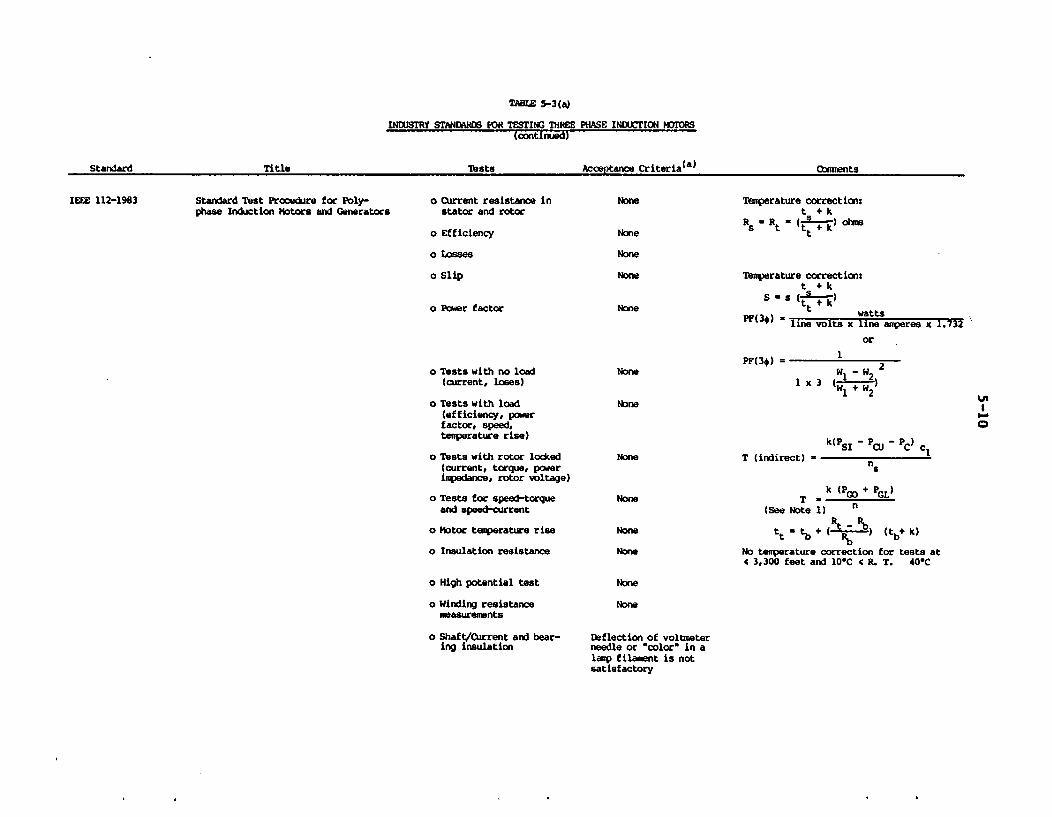
TALE 5-3(a)
INtUSTRY STANDMRDS FOR TESTING THREE PHASE INDUXTION MOTC@S(continued)
TitI. Aece.I-c Cr1-itei(a)Tests. oners.._. .__ .-
IEEE 112-1983 Standard Test Procedare for Poly-phase Induction Motors and Generators
o Current resistance instator and rotor
o Efficiency
o Losses
o Slip
None
None
None
None
Temperature correction:t + k
Rs Rt (t I ) ohmst
Temperature correction:t + k
S ts + kt+k watts
PF(3*) = line volts x line amperes x 1.732
or
o Power factor
PF(3#) =o Tests with no load
(current, loses)
o Tests with load(efficiency, powerfactor, speed,temperature rise)
o Tests with rotor locked(current, torque, powerimpedance, rotor voltage)
o Tests for speed-torqueand speed-current
o Motor temperature rise
o Insulation resistance
o High potential test
o Winding resistancemeasurements
o Shaft/Current and bear-ing insulation
None WI - W2 21 x 3 (w1 2+ 2)
Noneus
0
None
None
None
None
T (indirect) -
k(P5 1 'i- C PC) c
no
k (P + P GL)
(See Note 1) n
tt tb (tb+ k)
No temperature correction for tests atc 3,300 feet and 101C 4c R. T. 400C
None
None
Deflection of voltmeterneedle or "color" in alamp filament is notsatisfactory
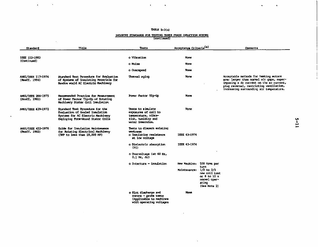
TAWZ 5-3(a)
INDUSTRY STANDYRDS FOR TESTING THREE PHASE INtXCTION MDTORS(continued)
a,...a.Ja)I'4 1 TURFS fhmmFnFq-- dl~r -X --L ..iNB rt~a''Llmfn:
IEEE 112-1983(Continued)
o Vibration
o Noise
o Overspeed
Thermal aging
None
ANSI/IEEE 117-1974(Reaff. 1984)
Standard Test Procedure for Evaluationof Systems of Insulating Materials forRandom would AC Electric Machinery
None Acceptable methods for heating motorsare: larger than normal air gaps, super-imposing a dc current on the ac current,plug reversal, restricting ventilation,increasing surrounding air temperature.
ANSI/IEEE 286-1975(Reaff. 1981)
ANSI/IEEE 429-1972
ANSI/IEEE 432-1976(Reaff. 1982)
recommended Practice for Measurementof Pouer Factor Tip-Up of RotatingMachinery Stator Coil Insulation
Standard Test Procedure for theEvaluation of Sealed InsulationSystems for AC Electric MachineryEmploying Formibund Stator Coils
Guide for Insulation Maintenancefor Rotating Electrical Machinery(SHP to less than 10,000 HP)
Power Factor Tip-Up
Tests to simulateexposures of coil totemperature, vibra-tion, humidity andwater immersion.
Tests to discern existingweaknesso Insulation resistance
at low voltage
o Dielectric absorption(PI)
o Overvoltage (at 60 Hz,0.1 Hz, dc)
o Interturn - Insulation
None
II.-A
IEEE 43-1974
IEEE 43-1974
New Machine: 500 Vrms perturn
Maintenances 1/2 to 2/3new coil testor 8 to 10 xnormal oper-ating(See Note 2)
o Slot discharge andcorona - probe tests(Applicable to machineswith operating voltages
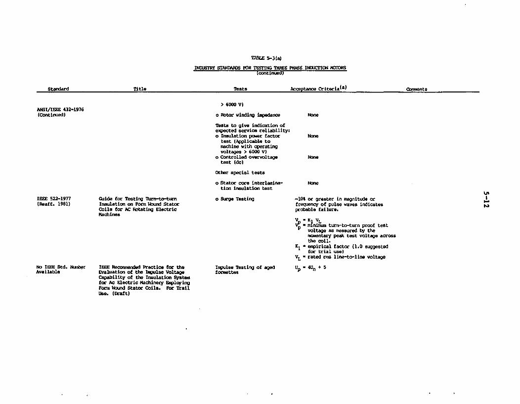
TAWE 5-3(a)
INDUSIRY STANDARDS FOR TESTING THREE PHASE INDUCTION MIOMRS(continued)
A--a. eyi-ar.:(a)V4 .1- lOoF4I ELF nPeru~~~ ~~~1 -;s .es nLzWbllw mnm
ANSXIEEE 432-1976(Continued)
> 6000 V)
o Rotor winding inpedanoe
Tests to give indication ofepected service reliability:o Insulation power factor
test (Applicable tomachine with operatingvoltages > 6000 V)
o Controlled overvoltagetest (dc)
Other special tests
o Stator core interlamina-tion insulation test
o Surge Testing
Inpulse Testing of agedformettes
None
IEEE 522-1977(Reaff. 1981)
No IEEE Std. NtmberAvailable
Guide for Testing Turn-to-turnInsulation on Form Wound StatorCoils for AC Rotating ElectricMachines
IEEE Reocc=eded Practice for theEvaluation of the Impulse VoltageCapability of the Insulation Systemfor Ac Electric Machinery EaplcyingForm Wound Stator Coils. For TrailUse. (Draft)
-10% or greater in magnitude orfrequency of pulse waves indicatesprobable failure.
VP min!" turn-to-turn proof testP voltage as neasured by the
mowntary peak test voltage acrossthe coil.
K1 , empirical factor (1.0 suggestedfor trial use)
VL = rated rms line-to-line voltage
Up -4Un + 5
UoI
I.
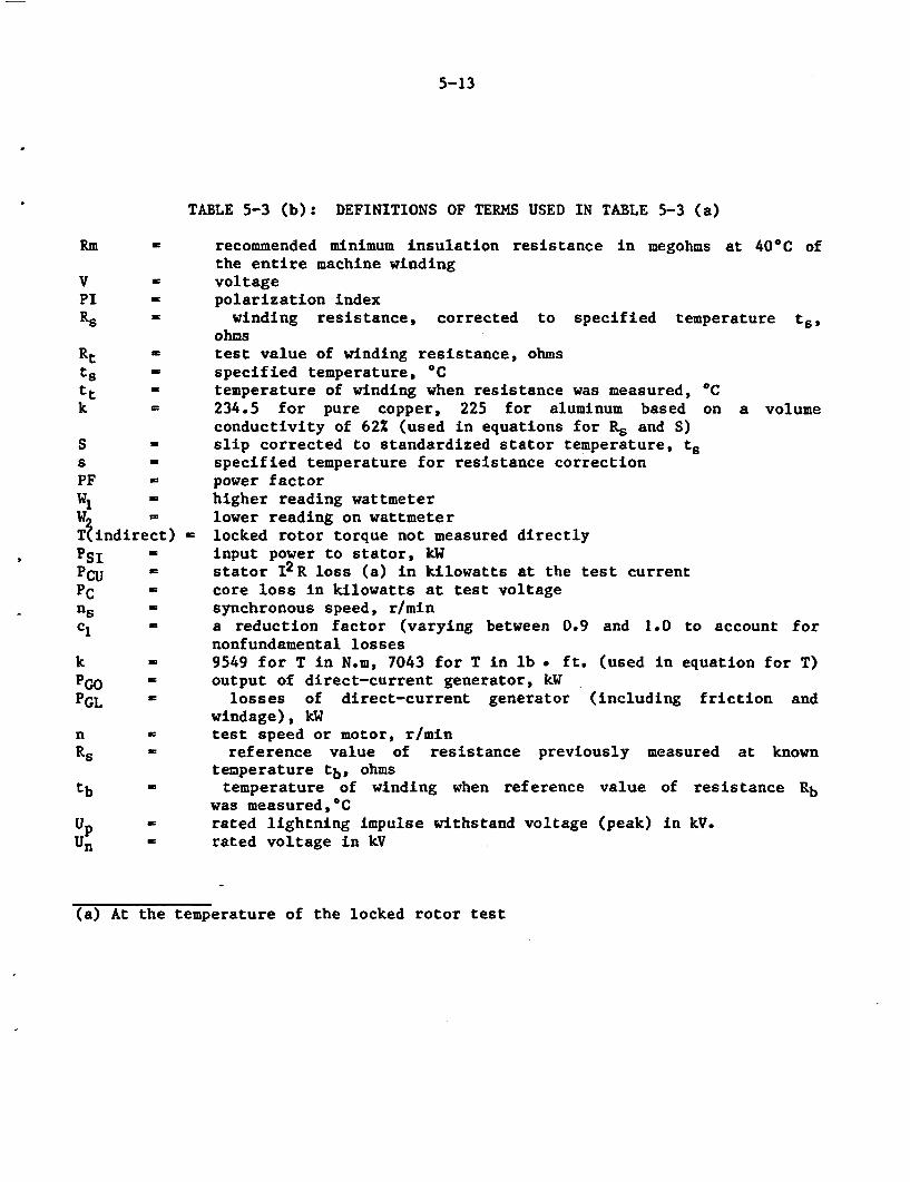
5-13
TABLE 5-3 (b): DEFINITIONS OF TERMS USED IN TABLE 5-3 (a)
Rm - recommended minimum insulation resistance in megohms at 400C ofthe entire machine winding
V = voltagePI - polarization indexRs = winding resistance, corrected to specified temperature ts,
ohmsRt = test value of winding resistance, ohmsts specified temperature, 0Ctt temperature of winding when resistance was measured, OCk - 234.5 for pure copper, 225 for aluminum based on a volume
conductivity of 62% (used in equations for R. and S)S - slip corrected to standardized stator temperature, tss - specified temperature for resistance correctionPF - power factorW- higher reading wattmeterW - lower reading on wattmeterT;indirect) - locked rotor torque not measured directly
Psi ' input power to stator, kWPCU stator 12 R loss (a) in kilowatts at the test currentPC core loss in kilowatts at test voltagen' synchronous speed, r/minc' a reduction factor (varying between 0.9 and 1.0 to account for
nonfundamental lossesk - 9549 for T in N.m, 7043 for T in lb * ft. (used in equation for T)PGO output of direct-current generator, kWPGL ' losses of direct-current generator (including friction and
windage), kWn = test speed or motor, r/minRs W reference value of resistance previously measured at known
temperature tb, ohmstb ' temperature of winding when reference value of resistance Rb
was measured,°CUp rated lightning impulse withstand voltage (peak) in kV.Un rated voltage in kV
(a) At the temperature of the locked rotor test
5-14
5.4 Industry Standards for Motors
While industry standards for motors are not written specifically for field test-ing, there are IEEE standards that provide guidance for monitoring the conditionof motors in the field. These tests are summarized in Table 5-3. Many of thesetests are referenced in the NEMA MG1 set of standards for the performance,safety, testing, construction and manufacture of all types of motors.
Some of these standards, such as ANSI/IEEE Standard 43-1974 (for the minimuminsulation resistance and polarization index), and ANSI/IEEE Standard 4-1978 (forinterturn insulation resistance) provide acceptance criteria. Even though thestandards lack the specificity that would make them more valuable for maintenancetesting and condition monitoring, the guidance and acceptance criteria could beuseful, in conjunction with industry experience, in providing a more standardizedsystematic approach to conducting maintenance and surveillancetesting.
5.5 EPRI Survey on Motors
In response to the draft NPAR Phase II motor report, the EPRI Equipment Qualifi-cation Advisory Group (EQAG) conducted, March 1987, a Motor Maintenance/Surveil-lance Survey (MM/SS) of the 56 EQAG member utilities with operating plants (44).Twenty-six plant sites responded from 24 utilities and the results were analyzedto augment the BNL survey findings based on the four plant discussed earlier.
While the practices do vary among utilities, there exists no distinction in prac-tices for safety related and non-safety related motors. The scope of the motorPM program appeared to be relatively independent of plant age. Although, thereis good agreement with the BNL findings, the survey suggests extensive practicesfor large motors. Dielectric tests such as power factor, surge, partial dis-charge tests are not typically performed by the industry, nor are they believedto be useful. With exception to a few test frequencies, the survey responsessupport many of the recommended PM practices identified in the BNL draft report.
Dielectric Tests and Monitoring - Insulation resistance and polarization indextesting are the dielectric tests performed most often on motors. The former testratings decreased with motor size while the latter test is reserved primarily forlarge and intermediate size motors. Although trending of these parameters arerecommended by a few, no assessment on the benefit of this activity with theaging condition of the insulation is provided. Other insulation tests includinghipot, power factor, surge, and partial discharge are not considered as effectivePM tests.
Monitoring of input voltage has no usefulness while the motor current data islargely used to determine if an excessive load is being placed on the motor dur-ing valve cycling, particularly during valve seating and unseating. The ratingsof this parameter for continuous duty motors appear mixed but clearly favor theuse of motor current for large motors. Use of winding temperature data is favor-ed for large motors and is clearly not recommended for small motors and MOVs.Trending of this data is performed by 12 utilities for large and intermediatesize motors.
5-15
Bearing Tests and Monitoring - Bearing tests include vibration tests and lubrica-tion analysis. The vibration data is trended by 20 out of 26 respondents where afew trended bearing temperatures. Although the vibration trending has beenproven beneficial, it is strongly recommended for large and intermediate sizemotors. The ratings are mixed for small motors excluding MOVs. Similar findingsare reported for lubrication analysis and bearing temperature monitoring with afew utilities performing this test on strictly large and intermediate sizemotors.
Speed measurement is neither performed nor recommended as an effective PM acti-vity. However, one respondent indicated that speed should be periodicallymeasured for MOVs.
Valve Stroke Timing - All safety related MOVs are required to be valve stroketiming tested according to the plant technical specifications and ASNE SectionXI. Half of the respondents appear to be performing no such testing for non-safety MOVs. All suggested this test as an effective PM practice. However, thevalue of this test for monitoring the condition of the motor degradation, inaddition to verifying valve operability, is not addressed by the survey.
General Inspections - Responses to this activity did not provide any recommenda-tions or ratings. However, the use of periodic walkdowns as an aid in determin-ing motor condition is encouraged. A few noted that general appearance andcleaning are incorporated into periodic maintenance activities.
5.6 Conclusions
Comprehensive survey of motor maintenance programs were conducted and the find-ings are summarized in Sections 5.2 and 5.5. A literature search on maintenanceactivities at nuclear utilities and a review of nuclear industry standardsrelated to motors have resulted in the following observations:
Although there is a trend in the nuclear industry to improve motor preventivemaintenance in power plants, the survey results indicate limited activities withregards to surveillance and periodic tests, and continuous monitoring programs.Important motors from the safety and cost stand-point are given a betterinspection, with periodic replacement of bearing oil, checking dirt in theinsulating systems as recommended by the motor manufacturer or based on the motoroperating experience.
Safety motors, including valve operators, are maintained as included in the main-tenance testing program, while some recently built plants have added certaintests or measurements to their plant tech specs or periodic tests. Theseinclude:
periodic insulation resistance/polarization index test,periodic measurement of motor running current (for valves this involvesboth valve closing and opening running currents),bearing vibration tests on continuous duty motors using portable measur-ing instruments,winding inspections for any abnormal conditions,bearing inspections for wear, bindings, water damages, and checking oillevel for sleeve bearings,stator-rotor clearance for any interference.
5-16
However, all physical parameters with exception to bearing vibrations are notgenerally monitored or trended for predicting the future condition. If any para-meter indicates an abnormal conditions, the motor is immediately repaired,cleaned or parts replaced. In addition to the above, the following prescriptiveequipment maintenance is done as a good maintenance practice,
* periodic replacement of bearing oil or grease,* periodic replacement of gasket,
cleaning (vacuuming or blowing) stator/rotor windings,tightening of loose bolts or nuts,
* cleaning the motor terminals,
Table 5-4 summarizes the current nuclear power plant motor PM programs.
With the exception of a few utilities identified in this section, there are onlylimited activities in condition monitoring or trending of any physical parameterfor assessing the future state of the motor. The periodic tests on motorsinclude the insulation resistance measurement only: the surveillance testing onsafety motor-driven equipment include running current, bearing vibration andvalve stroking. No industry standard, including ASME Section XI for pumps andvalves, addresses any ISI/IST requirement for motors. Continuous monitoring onmotors is limited to those of larger size driving pumps vital to plant availabil-ity. Both inspection and maintenance activities are performed as part of thegood practices learned from operating experience.
In conclusion, there exists no uniform program within the industry to performmotor PM in nuclear power plants. Many of the existing PM activities are aresult of operating experience, manufacturer's recommendations, a good industrypractice or regulatory commitment. Motor operational readiness is assessed oninsulation resistance or PI test. Running currents and winding temperatures aretypically reserved for valve operators or intermediate to large motors. Bearingperformance is maintained with periodic replacement of the grease or oil andsometimes in situ vibration measurements. Thus, one of the deficient areas thatappear to exist in current industry practices is the testing, monitoring, andinspection activities specific to detect the effect of aging in the insulatingsystem and bearing assemblies. Condition monitoring and/or trending of mainte-nance data is also not widely pursued to assess the present or the future stateof the motor components. Periodic testing on insulations, while effective indetecting insulation contamination at the time of the test, does not provide suf-ficient information to monitor the age-related degradations.
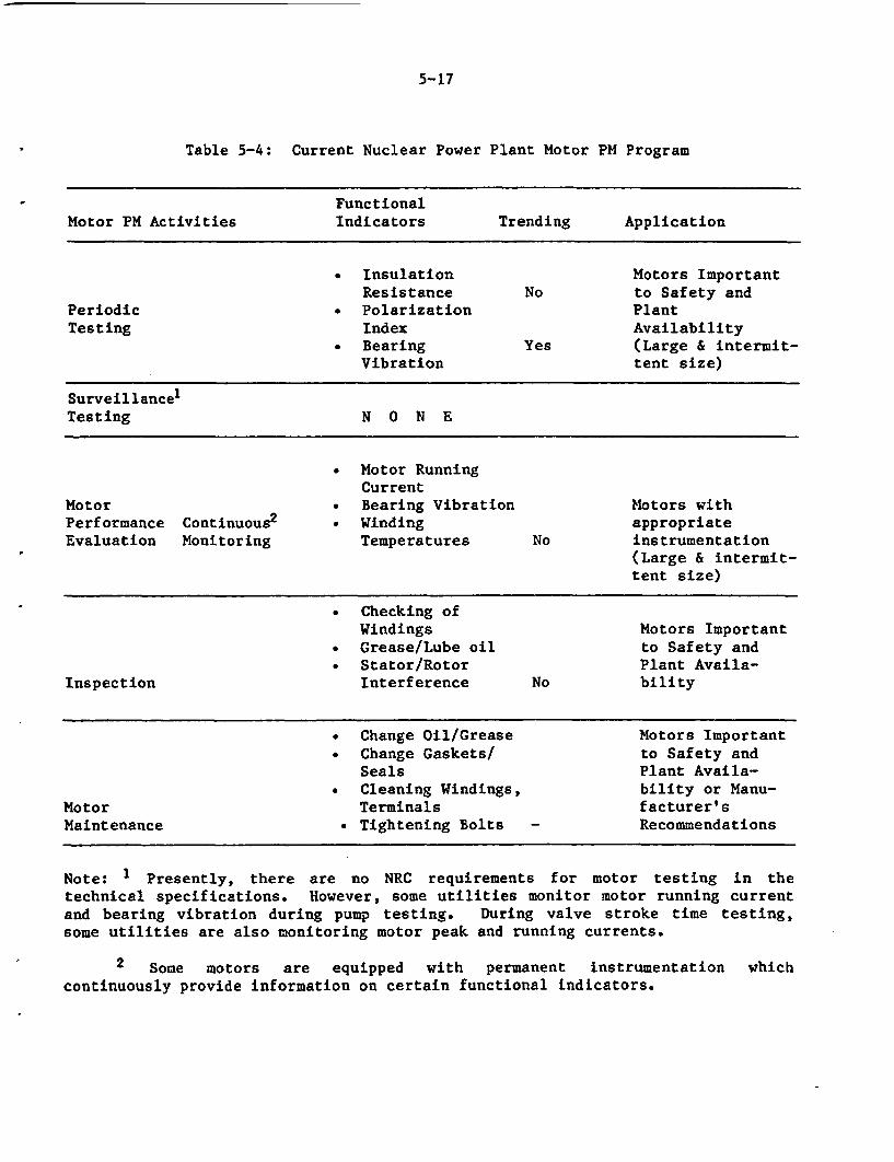
5-17
Table 5-4: Current Nuclear Power Plant Motor PM Program
FunctionalMotor PM Activities Indicators Trending Application
* Insulation Motors ImportantResistance No to Safety and
Periodic . Polarization PlantTesting Index Availability
* Bearing Yes (Large & intermit-Vibration tent size)
SurveillancelTesting N O N E
* Motor RunningCurrent
Motor . Bearing Vibration Motors withPerformance Continuous2 . Winding appropriateEvaluation Monitoring Temperatures No instrumentation
(Large & intermit-tent size)
* Checking ofWindings Motors Important
* Grease/Lube oil to Safety and* Stator/Rotor Plant Availa-
Inspection Interference No bility
* Change Oil/Grease Motors Important* Change Gaskets/ to Safety and
Seals Plant Availa-* Cleaning Windings, bility or Manu-
Motor Terminals facturer'sMaintenance . Tightening Bolts - Recommendations
Note: 1 Presently, there are no NRC requirements for motor testing in thetechnical specifications. However, some utilities monitor motor running currentand bearing vibration during pump testing. During valve stroke time testing,some utilities are also monitoring motor peak and running currents.
2 Some motors are equipped with permanent instrumentation whichcontinuously provide information on certain functional indicators.
6-1
6. MOTOR MAINTENANCE PROGRAMS
The nuclear industry motor maintenance programs typically are based on performingpreventive maintenance at prescribed intervals. If motor failure occurs prior tothe scheduled time for PM, then corrective maintenance is carried out. PM isperformed as scheduled, even if it is not required. The drawbacks to this phil-osophy are that untimely failures can occur causing a loss of availability, andunnecessarily high PM costs. A procedure to select a motor maintenance programfor a nuclear power plant is described, which would enhance its reliability andhence, the safety of the plant. It includes an application of the procedure forthe containment fan cooler motors and general discussions on application of cer-tain motors.
The primary objective of this study is to provide recommendations for the devel-opment of a cost-effective preventive maintenance program and to as sure that theoperational readiness of aged motors in a nuclear station is maintained through-out their design life. To achieve this goal, many factors must be consideredthat affect motor performance in a power plant, including design, manufacturing,construction, installation, operation, and maintenance testing. A properlyimplemented maintenance program as described here, can mitigate untimely motorfailures, thus improving motor reliability. This, in turn, will improve plantsafety and availability. Recommendations are provided on the application andfrequency of these maintenance tests and activities for the four class of motorsbased on their sizes.
6.1 Preventive Maintenance Philosophy
The overall maintenance program includes performance evaluation of the componentas well as maintenance activities. As discussed, performance evaluation containsfour basic elements: surveillance testing, periodic testing, continuous monitor-ing, and inspection. Surveillance testing in the nuclear industry includes thosemandatory tests obligated by the plant tech spec requirements. Periodic testingincludes in situ tests performed at the equipment or associated controls at sche-duled intervals to survey component degradations. Continuous monitoring, bydefinition, is the monitoring of certain functional indicators and hence,requires that data recording meters or other test equipment are permanentlyinstalled, to give continuous readings. Inspection of motors is defined as thoseactivities which do not require any test equipment or tools but include listeningto noise level, observing surface deteriorations, examining the mechanical/struc-tural strength of component monitoring, etc.
Major emphasis is given to (1) a good inspection program which is applicable toany size and type of motor in a nuclear facility, and (2) a continuous monitoringprogram for those motors with monitoring devices. These two activities arerecommended for all motors in a plant. However, the frequency of maintenance isdependent on the design function of the component and its importance to plantsafety and availabilty. These programs, augmented with-certain routine mainte-nance activities, based on the manufacturer recommendations and operating exper-ience, should eliminate most of the motor failures due to age and service-wear.
6-2
For predicting the future health of equipment, the test and inspection datashould be trended. Two tests have been performed to identify the functionalindicators that are most suitable for condition monitoring (or trending) and thecorrelation between them in detecting incipient defects. The following recom-mended practices assume that certain motors in nuclear power plants are designedand qualified to withstand any design basis accident environments.
Since a power plant contains motors of various sizes and types located throughoutthe facility, it is difficult to generalize motor characteristics for all plantenvironments and applications. Appendix D provides a discussion on motor size,type, and specifications used in safety applications in typical PWR and BWRdesigns. The motor population present would help to estimate the maintenanceeffort for implementing the recommended practices for a particular class ofmotors.
6.2 Reliability Centered Maintenance (RCM)
To achieve a better balance between preventive maintenance and corrective mainte-nance, and to maintain a high level of motor reliability, it is prudent to esta-blish a reliability centered maintenance program for motors (and for other impor-tant components).
RCM is a concept which uses an analytical methodology for establishing specificPM tasks for complex systems or equipment. Intrinsic to the concept is the iden-tlfication of critical failure modes and degradation mechanisms through engineer-ing analysis and field experience to determine the consequences and the mosteffective apportionment of maintenance activities. The phase I study on motorshas provided these needs (7).
The initial step in the RCM decision logic is to determine the criticality(safety or availability importance) of the component in question, in this case,motors. This is typically achieved by a failure modes and effect analysis (FMEA)or some similar methodology. The criticality of a component is affected by itssignificance to plant safety and availability, and considers features such as theavailability of redundant components. This step is plant specific and there areseveral publications which provide good treatment of the subject (41,42). Theremainder of the steps in RCM decision logic are discussed here. These steps,illustrated in Figure 6.1, result in a decision to perform one of the followingtypes of maintenance:
Corrective Maintenance: Not all failures will have a safety or plantavailability impact. If they are not more costly than PM, then the compo-nent can be allowed to fail and then taken out of service for repair orreplacement.
* Indicative Preventive Maintenance: Periodic and/or surveillance tests,continuous monitoring, and inspection data of components are used to deter-mine by condition monitoring (or trending) when a certain motor integrityhas degraded to the point where repair or replacement is required.
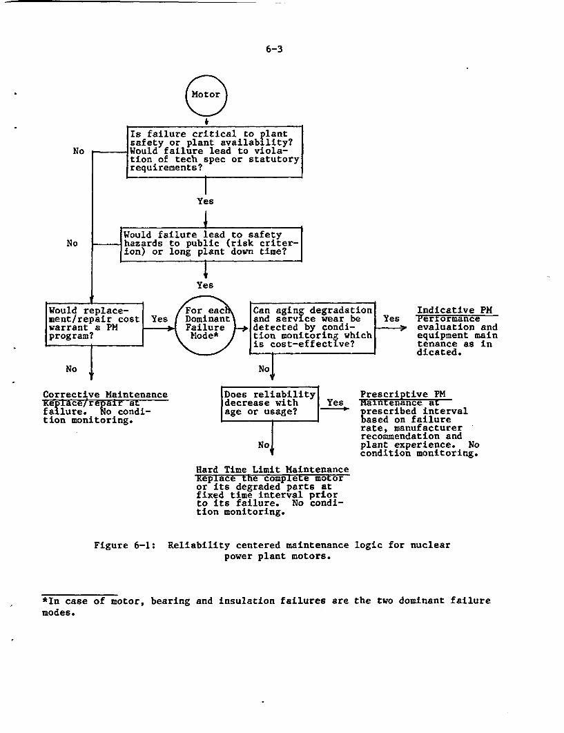
6-3
eNo
No
Is failure critical to Pilant?safety or plant availab lity?Would failure lead to viola-tion of tech spec or statutoryrequirements?
IYes
. _ IWould failure lead to safetyhazards to public (risk criter-ion) or long plant down time?
. i
Yes
Would replace- or e Can aging degradationment/repair cost Yes Dominant and service wear be Yeswarrant a PM Failure detected by condi-program? Mode* tion monitoring which
is cost-effective?I i-
Indicative PMFertormanceevaluation andequipment maintenance as indicated.
No No
. I
Corrective MaintenanceKeplace/irepair atfailure. No condi-tion monitoring.
Does reliabilitydecrease withage or usage?
No
YesPrescriptive PMmaintenance atprescribed intervalEased on failurerate, manufacturer -recommendation andplant experience. Nocondition monitoring.
Hard Time Limit MaintenanceReplace the complete motoror its degraded parts atfixed time interval priorto its failure. No condi-tion monitoring.
Figure 6-1: Reliability centered maintenancepower plant motors.
logic for nuclear
*In case of motor, bearing and insulation failures aremodes.
the two dominant failure
6-4
* Prescriptive Preventive Maintenance: Certain motors do not warrant anysophisticated testing because of their minimal cost or unimportance to theplant safety and availability, or because condition monitoring techniquesdo not provide sufficient information to make PM decisions. The failurerate of such motors establishes these prescriptive maintenance intervals.No condition monitoring is required. This also includes recommended mainte-nance practice which require all scheduled activities, such as regressing,oil changes.
* Hard Time Limit Preventive Maintenance: This is a prescribed PM program,where it is established that the reliability of the component remains unaf-fected by age or usage, and a PM program does not guarantee detection ofthe degradation at an incipient stage. Since the component is importantfor plant operation, the complete motor assembly or the degraded subcompo-nents are replaced at fixed time intervals prior to failure, based on themanufacturer recommendations or operating experience.
Thus, depending on the design requirements of the motor in plant operation, eachnuclear plant motor can be assigned one of these maintenance programs. Allimportant motors, which include all safety and intermediate to large non-safetymotors, are considered for a PM program. The motors are filtered through thelogic chart in Figure 6-1 to determine a cost effective PM program. If the costof the PM program is prohibitive, then corrective maintenance is chosen. On theother hand, preventive maintenance is chosen if the motor is vital to plant oper-ation and the costs of failure are prohibitive.
If any particular failure mode can be diagnosed with a cost-effective conditionmonitoring program, then the motor is considered for trending, using its func-tional indicators (FIs). Subsequent maintenance is performed as indicated by theFl trends. Where condition monitoring does not provide adequate information forPM decisions, but the motor reliability is affected with age, then it is subject-ed to prescriptive PM. Finally, if the particular failure mode does not affectthe motor reliability, the aged subcomponents (or the complete motor assembly)contributing to this failure can be repaired or replaced at certain prior fixedtime intervals.
Besides the design function and its importance to plant operation, other elementswhich govern the PM decision for nuclear power plant motors are:
. Location - Motors are located inside the containment and other high radia-tion areas, outside the containment, indoor/outdoor, and at elevations withdifficult accessibility. Depending on this, the frequency and kind oftesting should be optimized to limit personnel exposure, and remote moni-toring should be considered.
* Environment - The aging process of motors is directly dependent on the typeof environment to which they are exposed. All motors in a harsh environ-ment are qualified for the lifetime of the plant and designed to operatein an accident. Motors in mild environment can be tested without too muchdifficulty. The outdoor motors that are exposed to hostile environmentsuch as salty air, should be considered for condition monitoring.
6-5
* Operation - Motors are either operated under normal condition, in accidentconditions, or in post-accident conditions for safe shutdown of the plant.Motors are used for continuous duty and standby operation, as in the caseof safety motors. Valve motors are typically of the intermittent type. Asis evident from the aging assessment, continuous duty motors experience alesser degree of aging when compared to the others. Also, many timesexcessive testing on standby and intermediate duty motors induce acceler-ated aging, leading to premature failure.
Failure modes - As evident from the preceeding study, bearing and insula-tion failures contribute to most motor failures. In some cases, the causeof a motor failure can be external, such as misapplication, misoperation,or the failure of the driven component. Hence, in establishing the failuremodes for a particular motor, specific plant experience data on the subjectoperation should be taken into account.
One of the most important advantages of an RCM over other maintenance tools isthat the decision tree helps change the maintenance intervals, depending on thepast reliability of a particular component. If the motor has excellent reliabil-ity and the trended data indicates no subcomponent degradation, the maintenanceintervals can be relaxed or optimized for future Maintenance, and vice versa.This would also help in establishing the residual life of the component for plantextension, in case it is needed. To accomplish this, each plant must maintain agood data base for each component including its design and manufacturing specifi-cations, qualification and installation documents, operating and maintenance his-tories, and maintenance data and their trends. With these elements in data base,the RCM decision tree can provide much useful information in detecting and miti-gating degradation and failure.
6.3 RCM Logic Application for Containment Fan Cooler Motors
Containment fan cooler motors were chosen, due to their location in a radiationzone and the requirement that they remain operational in an accident environment.For certain designs, these fan coolers must operate up to a year in a post-acci-dent humid and chemically contaminated environment. Since this environment isdetrimental to the motor insulation and bearings, one study (4) has recommendedhermeticlly sealed motors for this application.
A specific PWR was chosen for evaluation, which has five 225 hp fan coolermotors. Three of the five fan coolers are required to operate to manage accidentloads, but less than three are sufficient if containment spray capability isavailable. Teichnical specification requirements are such that the plant isplaced in an LCO (Limiting Condition for Operation) if one of the fan coolers isunavailable. These fan coolers require electric power and service water for pro-per operation.
A review of failure data from industry indicates that these motors are very reli-able. There have been about 20 fan cooler motor failures reported industry-wideduring the period 1976 to 1983: this is greater than one failure every one hun-dred years of operation. Approximately half of these are attributed to bearingfailures and half to insulation winding burnouts. The root cause of thesefailures is presumably due to impingement from water cooler leaks. The
6-6
probabilistic risk assessment for the subject plant in the case study used amotor failure rate of 3.23 x 10⁻³ per year, which means that one motor can beexpected to fail after 300 years of operation, or for five motors, a failure canbe expected every 60 years. If one thinks back to THI (Three Mile Island), thefan cooler motors continued to operate during and after the accident.
With motors that are so reliable, a high activity, high frequency maintenanceprogram is not required. On the other hand, one certainly would not want to havethese motors in a degraded condition, such that they could not operate through adesign basis accident. What is required is a maintenance program that providesinformation on the "health" of the motors.
The present tech spec requirements for operability on each group of containmentcooling fans are:
a) at least once per 31 days:
. start each fan group from control room and verify that each fangroup operates for at least 15 minutes.
verify cooling water flow rate of greater than or equal to a spe-cific number for each cooler
b) at least once per 18 months, verify that each fan group starts automa-tically on a particular test signal.
The tests do not provide any specific information on motor condition and there isno assurance of the operational readiness of these motors through the next testperiod. However, trending certain electrical or mechanical parameters taken fromthese tests could enhance the motor (hence the fan cooler) reliability.
To demonstrate the application of the recommended procedures outlined in Figure6-1 logic diagram for containment fan cooler motors the following is presented:
* Is failure critical to plant safety and/or plant availability? Yes.The motors are safety related and one failure would place the plant inan LCO condition.
* Would failure lead to safety hazard to public (risk criteria) and/orlong plant down time? A calculation performed with the PC based riskprogram "NSPKTR," indicated that for a failure of one fan cooler motor,there is no perceptible change in plant risk. This would seem to makethe answer to the above question a No, and if the decision was basedsolely on reliability concerns, a No answer would be acceptable. How-ever, in consideration of the tech spec LCO criteria and the inacces-sibility of the motor during normal operation, a YES answer is selected.
Would replacement/repair cost warrant a PM program? Yes. Given ALARAconcerns and the potential for forced plant outages, and the opportunityto avoid costly equipment damage, it is presumed that a utility wouldprefer to repair or replace the motor under planned conditions such asrefueling outage.
6-7
Based on the above, the motors in the subject plant should have a cost-effectivePM program. The typical failure modes associated with these motors are bearingfailures due to lack of lubrication, and the insulation burnout (primarily due tointrusion of water into the windings).
Other elements to be considered for this motor application are:
* Location - located inside containment and at an elevation not readilyaccessible.
* Environment - harsh environment. Should be designed to withstand post-accident environment with chemical and water spraying on motors.
* Operation - although not all motors run all the time, some motors func-tion during normal operating conditions. They are designed to remaincontainment.
* Failure Modes - bearing and insulation failures.
Considering these factors, the following questions can be answered asfollows:
Bearing Insulationfailure failure
Can aging degradationand service wear bedetermined by conditionmonitoring which is cost-effective? Yes Yes
Maintenance Recommendations for Fan Cooler Motors
Perform preventive maintenance which includes (see Sections 6.4.1 - 6.4.4):
1) Performance evaluation:
a) Inspection - Physical inspection of motors every refueling outage (seeAppendix C.2).
6-8
b) Continuous monitoring - Since these motors require high reliabilityand are intermediate in size, line/phase current, winding tempera-tures (if any), and bearing temperatures should be continuously moni-tored. As a minimum, current and voltage can be monitored (seeAppendix C.1).
c) Surveillance testing - There are no specific surveillance testrequirements for these motors. However, recording the speed andwinding temperatures every refueling outage would help monitor thebearing and insulation conditions (see Section B).
d) Periodic testing - Insulation resistance and polarization index atevery month prior to fan start up testing should be performed todetermine its dryness and accumulation of foreign particles. At thesame time partial discharge (corona) testing as well as power factortesting should be performed to monitor any corona discharge inceptionand average condition of the insulation respectively. Vibration testson bearings also should be performed each refueling outage or everyother time. This infrequency is due to the low failure rate (seeAppendix A).
e) Condition monitor - All of the above data should be trended andanalyzed. Any adverse trends should be further analyzed for rootcause and corrective maintenance performed as necessary (see Section3).
2) Equipment maintenance:
This should include all corrective measures as indicated by the trendsobtained from the above activities. Periodic cleaning of insulation,lube oil changes, and other good housekeeping measures should be per-formed as necessary to keep the motors in good operating condition.Measures should be taken to ensure that water leaks from the cooler donot impinge onto the motor components.
6.4 Summary of Maintenance Practices
The present preventive maintenance practices in nuclear power plants includescheduled inspections, line/phase current monitoring, and periodic tests suchas insulation resistance and polarization index tests. Manufacturer- recom-mended maintenance includes periodic changes of oil or lubrication and carbonbrush replacements. Vibration should be measured on certain safety classmotors or motors (above 25 hp) important to power generation. Some utilitiesare installing on-line monitoring equipment to continuously monitor some func-tional indicators, such as bearing vibration and line/phase current or voltageon a selected number of motors important for plant operation and safety. Mostof t he other test methods described in this report typically are used in theindustry for detecting the location of faults in various motor sub-componentsas a part of the corrective maintenance program.
6-9
If a motor is operated without any maintenance, it will eventually fail. Toresume operation it must be repaired or replaced (i.e. corrective mainte-nance). The total cost incurred as a result of availability/capacity lossesdue to motor failure and repair will be larger than the cost of a preventivemaintenance program. Further, if a good preventive maintenance program is ineffect, few unexpected failures should occur. Since the action is planned, itcan be scheduled around plant operating conditions and therefore, will notimpact plant availability. However, if the periodicity of PM activities isunnecessarily large, high costs will result as well as test-induced componentdegradations. The frequency of a good PM program lies somewhere in betweenthe two extremes. A reliability-centered approach is recommended to establishthe maintenance program for motors in nuclear facilities.
One element missing in the current industry PM activities is the capability topredict the future performance of motors. No industry standards or publisheddocuments are available identifying the FIs suitable for condition monitoringof motor performance. Thus, the overall preventive maintenance pro gram formotors is a collaborative effort of performance evaluation and certain equip-ment maintenance activities. Some of these maintenance activities may be rou-tine, based on manufacturer's recommendations or operating experience whileothers may be as a result of an indication of abnormality in any of the FItrends obtained from tests or measurements. Specifically, many regularinspection schedules for evaluating the motor performance may be germane main-tenance activities such as lube oil change, changing air filters or gaskets,replacing carbon brushes or parts with a finite life due to age or servicewear, cleaning winding or commutator surfaces, readjusting components, andrecalibrating instruments. The following is a summary of the recommendedpractices which could be included in a good PM program, to assure the opera-tional readiness of any motor (including inside containment) designed to oper-ate during normal as well as accident conditions. It should be noted that therecommended frequency of a particular activity is based on engineering judge-ment and a typical refueling outage schedule of 18 months for nuclear powerplants. Not necessarily all recommended tests are required for monitoring aspecific application motor. Suitable test methods should be considered forinclusion in the existing maintenance programs depending on the test intru-siveness, equipment accessibility, and operational requirements of the candi-date motor.
6.4.1 Periodic Tests
Periodic tests described in Appendix A typically are used either subsequent tocorrective maintenance on any motor or for routine testing on high voltage -intermediate to large size motors. Table 6-1 summarizes some of these testprocedures for preventive maintenance. Some of the FIs included are suit ablefor trending in order to predict the future motor performance. Insulationresistance/polarization index tests, and surge tests may not suitable for con-dition monitoring. However, IR/PI tests are go/no-go type tests and importantfor pre- or post-maintenance operation of motors. PF/DF tests and partialdischarge test are used to detect void growth and corona discharge activitiesin insulation. Use of voltage impulse/surge testing on motors providesinstant voltage/current wave forms which are compared with those correspondingto good insulation.
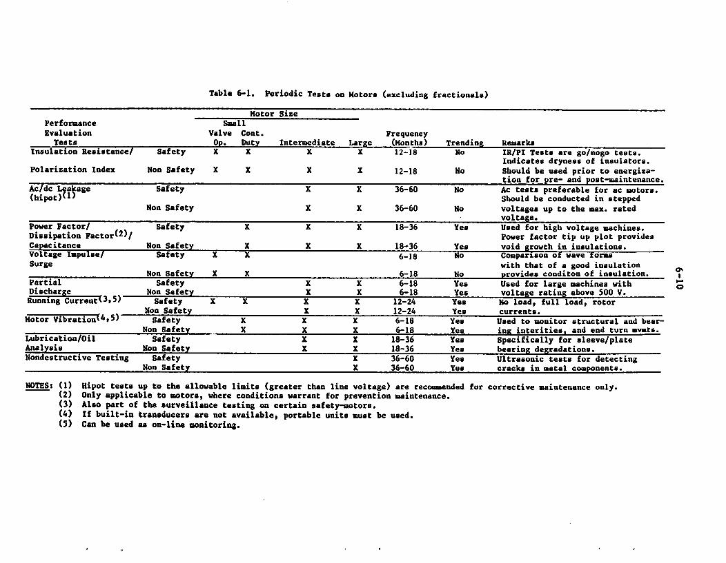
Table 6-1. Periodic Tests on Motors (excluding fractional.)
Motor SizePerformance SmallEvaluation Valve Cont. Frequency
Tests Op. Duty Intermediate Large (Months) Trending Remarksinsulation Resistance/ Safety X X X X 12-18 No IR/PI Tests are go/nofo tests.
Indicates dryness of insulators.Polarization Index Non Safety X X X X 12-18 No Should be used prior to energiza-
tion for pre- and post-maintenance.Ac/dc Lestage Safety X X 36-60 No Ac tests preferable for ac motors.(hipot)'1I Should be conducted in stepped
Non Safety X X 36-60 No voltages up to the max. ratedvoltage.
Power Factor/ Safety X X X 18-36 Yes Used for high voltage machines.Dissipation Factor(2)/ Power factor tip up plot providesCapacitance Non Safety X _X X 18-36 Yes void growth in insulations.Voltage Impulse/ Safety X X 6-18 No Comparison ot wave formsSurge with that of a good insulation
Non Safety X X 6-18 No provides conditon of insulation.Partial Safety X X 6-18 Yes Used for large machines withDischargeNon Safety X X 6-18 Yes voltage rating above 500 V.Running Current 3,5) Safety K X X X 12-24 Yes No load, full load, rotor
Non Safety X X 12-24 Yes currents.Motor Vibration%415) Safety X X X 6-18 Yes Used to monitor structural and bear-
Non Safety X X X 6-18 Yes ing interities, and end turn mvmts.Lubrication/Oil Safety X X 18-36 Yes Specifically for sleeve/plateAnalysis Non Safety X X 18-36 Yes bearing degradations.Nondestructive Testing Safety X 36-60 Yes Ultrasonic tests for detecting
Non Safety X 36-60 Yes cracks in metal components.
NOTES: (1) Hipot tests up to the allowable limits (greater than line voltage) are recommended for corrective maintenance only.(2) Only applicable to motors, where conditions warrant for prevention maintenance.(3) Also part of the surveillance testing on certain safety-motors.(4) If built-in transducers are not available, portable units must be used.(5) Can be used as on-line monitoring.
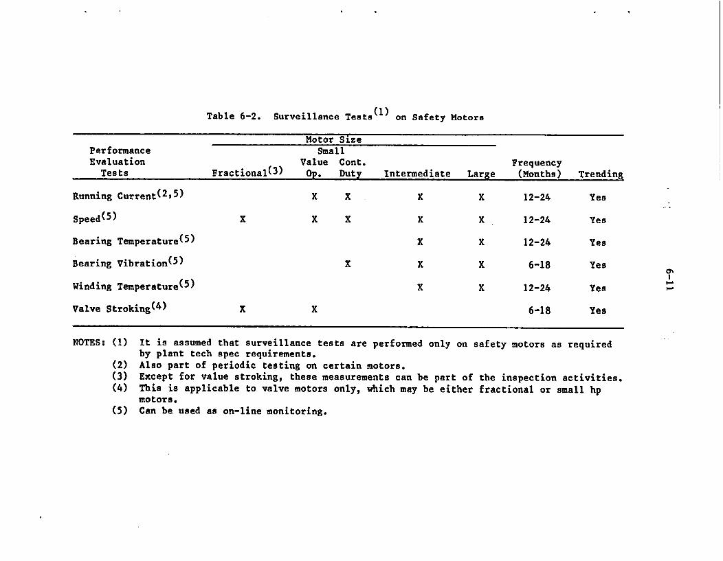
Table 6-2. Surveillance Tests(l) on Safety Motors
Motor SizePerformance SmallEvaluation Value Cont. Frequency
Tests Fractional(3) Op. Duty Intermediate Large (Months) Trending
Running Current(2,5) X X X X 12-24 Yes
Speed(5) X X X X X 12-24 Yes
Bearing Temperature(5) X X 12-24 Yes
Bearing Vibration(5) X X X 6-18 Yes
Winding Temperature(5) X X 12-24 Yes
Valve Stroking(4) X X 6-18 Yes
M
NOTES: (1) It is assumed that surveillance tests are performed only on safety motors as requiredby plant tech spec requirements.
(2) Also part of periodic testing on certain motors.(3) Except for value stroking, these measurements can be part of the inspection activities.(4) This is applicable to valve motors only, which may be either fractional or small hp
motors.(5) Can be used as on-line monitoring.
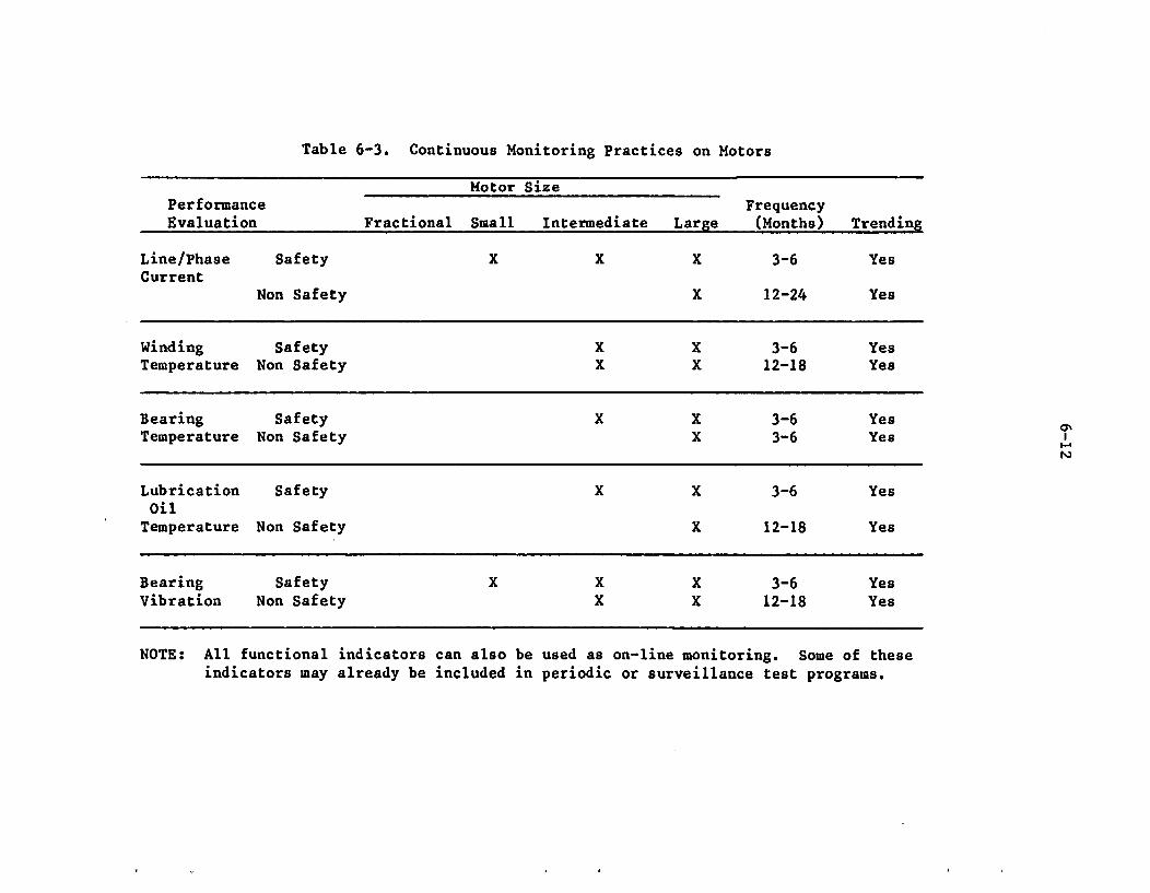
Table 6-3. Continuous Monitoring Practices on Motors
Motor SizePerformance FrequencyEvaluation Fractional Small Intermediate Large (Months) Trending
Line/Phase Safety X X X 3-6 YesCurrent
Non Safety X 12-24 Yes
Winding Safety X X 3-6 YesTemperature Non Safety X X 12-18 Yes
Bearing Safety X X 3-6 YesTemperature Non Safety X 3-6 Yes
Lubrication Safety X X 3-6 YesOilTemperature Non Safety X 12-18 Yes
Bearing Safety X X X 3-6 YesVibration Non Safety X X 12-18 Yes
I-
NOTE: All functional indicators can also be used as on-line monitoring. Some of theseindicators may already be included in periodic or surveillance test programs.
6-13
6.4.2 Surveillance Tests
No industry wide surveillance requirements on motors exist in the currentplant tech specs. Appendix B describes some of the FIs either used, or whichcan be used , to survey motors in nuclear facilities. Table 6-2 summarizesthese parameters with their suitability for inclusion in a plant PM program.Some of these evaluations are already being obtained in the nuclear industryfor pumps and valves as components, including their drivers (i.e. motors).These include the motor running current and speed for pumps, and valve strok-ing for MOVs. Bearing and winding temperatures, and bearing vibration signa-tures are typically monitored for larger motors (above 50 hp). These indica-tions are useful for surveying the insulating system and bearing conditions ofmotors. It is therefore recommended that these FIs be included in the presentsurveillance program and the data be analyzed for trending as a part of theplant PM program.
6.4.3 Continuous Monitoring
Table 6-3 summarizes the suitability of each of the continuous monitoringparameters described in Appendix C, and their recommended frequencies. Notethat small safety motors should be periodically monitored for winding tempera-tures, voltage/current reading, and bearing vibration levels. If devices arenot built into the motor components, portable test units must be used toobtain this information. It is assumed that intermediate and large sizemotors are equipped with devices to denote the recommended functional indica-tors directly on the display or dials.
6.4.4 Inspection
Figure 6-2 provides the "10-point" inspection checklist (see Appendix C)applicable to all sizes and types of motors utilized in nuclear power plant.Cleaning or other maintenance activities that may be performed along with theinspection depend on the condition of the motor and the need for such activi-ties for good engineering practices. A 3-6 month inspection schedule forsafety motors and 12-18 month for nonsafety motors are recommended. Trendingof inspection FIs helps to predict future performance, and when compared withthe previous inspection data, may help to diagnose any abnormality in motorperformance history.
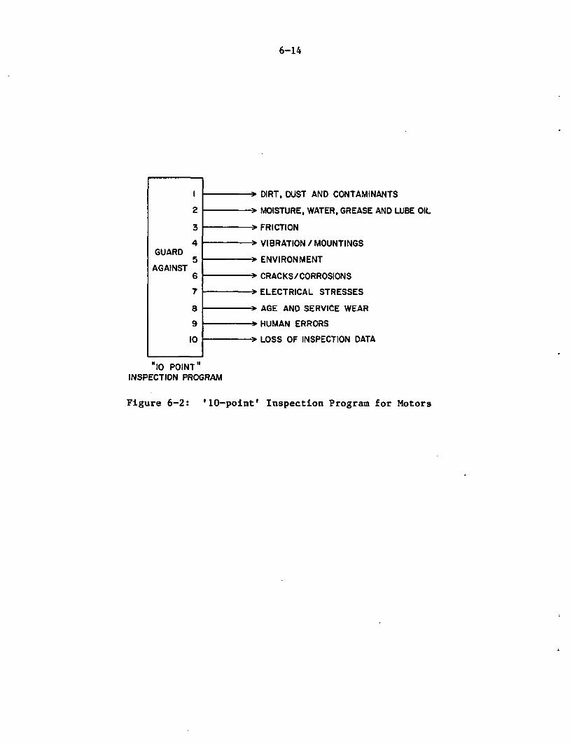
6-14
2
3
GUARD
AGAINST
4
5
6
7
89
I0
- DIRT, DUST AND CONTAMINANTS
- MOISTURE, WATER, GREASE AND LUBE OIL
- FRICTION
- VIBRATION/ MOUNTINGS
- ENVIRONMENT
- CRACKS/CORROSIONS
- ELECTRICAL STRESSES
- AGE AND SERVICE WEAR
- HUMAN ERRORS
- LOSS OF INSPECTION DATA
t10 POINT"INSPECTION PROGRAM
Figure 6-2: '10-point' Inspection Program for Motors
7-1
7. CONCLUSIONS AND UTILIZATION OF RESULTS
The insulating system and bearing assemblies were found to be the dominantfailure modes accounting for almost seventy percent of the reported failures.A survey of four nuclear stations revealed that the current nuclear powerplant motor preventive maintenance programs include insulation resistanceand/or polarization index tests to monitor the dielectric integrity of motors.In certain motors, bearing vibration levels are measured to assess the rota-tional integrity. The plant technical specification does not include anyspecific tests f or motor performance checks, however, it includes the motordriven equipment overall performance tests. Motor operated valves are testedfor valve stroking where pumps for speed and flow checks. Additionally, thecurrent maintenance programs consider periodic oil/grease changes, windingcleaning, and tightening bolts as recommended by the manufacturers.
7.1 Conclusions
In conclusion, motors important to plant safety and availability to powergeneration should undergo cost-effective preventive maintenance programs.These include indicative, prescriptive, and hard time limit maintenance,depending o n their application and reliability as discussed in the report.Other nonsafety motors may be allowed to fail and corrective maintenance canbe performed to r e store their design functions. The frequency of any acti-vity can be optimized as the performance of a motor has improved.
For the performance evaluation of motor condition (after application of RCMlogic), the preventive maintenance program should include the following testsand inspections:
Periodic Testing: In addition to the current practices (i.e. insula-tion resistance and polarization index tests), smaller size motorswith random wound coils should be considered for surge test to detectlocal defects in the insulation. Dissipation factor/capacitance testshould be performed to monitor the average condition. Bearings formotors above 25 hp are candidates for periodic vibration testing.For intermediate to large motors, the partial discharge (or corona)test should be considered for hot spots or corona discharges wherethe power factor or dissipation factor test is suitable for monitor-ing average insulation condition.
Surveillance Testing: Motor running current and motor bearing vibra-tion should be measured and recorded during surveillance testing ofthe pumps, fans, and valves required by the present plant technicalspecifications. Provided the motor is equipped with measuringdevices, the winding and bearing temperatures are good indicators fordegraded components and should also be measured and trended duringsurveillance testing.
Continuous Monitoring: All motors equipped with permanently instal-led devices should be monitored continuously or periodically. Thedata should be analyzed for condition monitoring and trending.
7-2
* Inspection: A comprehensive checklist for a good inspection programshas been recommended for implementation. The plant specific listshould minimize any human errors in registering the data in thechecklist.
• Condition Monitoring and Trending: Testing performed on those motorsrequired for maintaining their operational readiness, should betrended. The future health until the next scheduled tests can beassessed by recording and analyzing the data each time a test is per-formed. There- fore, it is important that for each functional indi-cator a baseline parameter value should be developed first, prior tosubjecting the motor to an in-service condition. If the motor issubjected to a particular test or inspection, then the data should beassessed comparing this with the previous set of test data or a base-line data for monitoring the present condition.
Equipment Maintenance: Regular maintenance activities include greas-ing/oil change, gasket and seal replacement, periodic cleaning ofwindings and terminals, bolt tightening, and others recommended bymanufacturers. The frequency of these activities, as well as certainspecific maintenance activities should be developed based on theplant operating experience. Depending on the overall performance ofa motor, the maintenance scheduling can be changed to optimize themaintenance program.
To develop a complete maintenance program, the frequency of the above activi-ties should be determined after considering the following:
accessibility to the motor or controlsimportant to plant safety " test equipment andits intrusivenesscost versus benefitsplant scheduling and outages
* system operating modes. motor design and specifications
Precautionary measures should be taken to avoid any test induced degradationon motors. Certain maintenance tests can be performed at the motor controlcenters or switchgear. Some require the motor to be out of service, but notnecessarily disconnected from power leads. For those cases when the discon-nection of power leads are necessary, nuclear grade connectors (known asElastomolds) are available to be installed inside the conduit box for motorsup to 5,000 volts ratings. These connectors aid in providing electrical powerto motor without disconnecting the leads.
7.2 Utilization of Results
The only guide available for motor maintenance is the IEEE-Std 432-1976entitled "IEEE Guide for Insulation Maintenance for Rotating ElectricalMachinery." This standard refers to the dielectric integrity of motors rangingin sizes from 5 hp to 10,000 hp. The guide contains a good description of theinsulating system and the applicable inspection and test procedures. It dis-cusses the applicability of various test methods which are typically used
7-3
as a regular maintenance practice. No reference is made to preventive or cor-rective maintenance, except to the importance of service reliability. Effectsof aging and service wear of other motor components are not included, nor isthe condition monitoring of various FIs for predicting future health. Thus,the standard could be improved or a new standard may be developed as a resultof the current Power Engineering Society (IEEE/NPEC) activities for motormaintenance practices. The emerging standard may address all the three inte-grities (dielectric, rotational, mechanical) and their testing and maintenancepractices to mitigate age and service wear related failures.
Knowing the aging characteristics (7) of motor components, the impact ofenvironmental and seismic effects (43) on the motor performance can includesuch effects in qualifying motors for nuclear applications. The standards andguides requiring updates are IEEE-Std 323, IEEE-Std 344, and Regulatory Guide1.89. It should be noted that small induction motors with adequate qualifica-tion are rugged enough to withstand both design basis nuclear environment andseismic loads. Large motors, specifically vertical motors, with many addi-tional protective and operational features require further studies to estab-lish their aging/seismic correlation.
The present tech spec requirement written for any plant basically focuses onthe driven component, rather than the driver itself. ASME Section XI, whichaddresses the in-service testing and monitoring procedure, needs to includeother FIs suitable for motors.
Lastly, the research findings will help both nuclear power industry and theregulatory agency to resolve various safety concerns in reference to motors.Implementation of a good PM program, which will improve the plant safety andplant availability, can help to provide a reliable plant performance record.Hence, if any plant applies to have its operating license extended, the plantrecords will help the regulating agency in -determining the extension.
8-1
8. REFERENCES
(1) Cornell, E.P., et al., "Improved Motors for Utility Applications," Vols.1 and 2, EPRI EL-2678, October 1982.
(2) Clay, H.R., Wanless, J.W., Brancato, E.L., "Life Expectancy of Motors inMild Nuclear Plant Environments," EPRI NP-3887, February 1985.
(3) Mullen, D.M., "Specify Motors by Starting Duty, Not Running Duty," Power,pp. 55-57, February 1985.
(4) Fields, C.V., et al., "Application of Electrical Insulation to NuclearReactor Containment Motors," IEEE Trans.
(5) Nailen, R.L., "Test Standards for Nuclear Plant Motors," Power Engineer-ing, pp. 39-41, December 1971.
(6) Emery, F.T., Gottlieb, M., Brandt, J.B., "Electric Generator Monitoringand Diagnostics," EPRI NP-2564, September 1982.
(7) Subudhi, M., Burns, E.L., Taylor J.H., "Operating Experience and Aging-Seismic Assessment of Electric Motors," NUREG/CR-4156, June 1985.
(8) Perla, H.F., et al., "A Guide for Developing Preventive Maintenance Pro-grams in Electric Power Plants," EPRI NP-3416, May 1984.
(9) Seminara, J.L., Gonzalez, W.R., Parsons, S.O., "Maintainability Assess-ment Methods and Enhancement Strategies for Nuclear and Fossil Fuel PowerPlants," EPRI NP-3588, July 1984.
(10) Armor, A.F., "Incipient Failure Detection for Fossil-Power-Plant Compo-nents: 1982 Conference and Workshop," EPRI-CS-2920, March 1983.
(11) "In-service Testing of Pumps in Nuclear Power Plants," Subsection IWP,ASME B&PVC, 1980.
(12) "Inservice Testing of Valves in Nuclear Power Plants," Subsection IWV,ASME B&PVC, 1980.
(13) Fromm, M.M., "Tests for Turn Insulation in Large Machines" Power Engi-neering, pp. 70-72, November 1978.
(14) Reason, J., "Why Dielectric Failure Is the Major Cause of Electrical Sys-tems Breakdown," Power, Vol. 125, No. 7, pp. 35-50, McGraw-Hill, Inc.,New York, July 1981.
(15) "IRD Mechanalysis Operator Manual for Vibration/Spike Energy Analyzer,"IRD Mechanalysis Inc., 1981.
(16) "Machine-Health Monitoring," Bruel & Kjaer marketing booklet.
(17) "On-Line Diagnostics for Power Plant Machinery," EPRI Journal,p. 44-46,Electric Power Research Institute, Palo Alto, CA., July/August 1979.
8-2
(18) "Velocity Measurements Recommended for Periodic Vibration Checks," IRDMechanalysis, Engineering Report No. 101.
(19) Krigman, A., "Acoustic Emission: Nondestructive Testing Moves On Stream,"In Tech, pp. 7-16, August, 1985.
(20) Williams, D., "Acoustic Emission Testing of Reactor Coolant Pump MotorFlywheels," Power Engineering, pp. 62-63, October 1984.
(21) Callacott, R.A., "Mechanical Fault Diagnosis and Condition Monitoring,"John Wiley & Sons, New York, 1977.
(22) Baxter, N.L., "Vibration and Balance Problems in Fossil Plants: IndustryCase Histories," EPRI CS-2725, November 1982.
(23) Sugarman, A., Kumar, B., Sorensen, R., "Condition Monitoring of NuclearPlant Electrical Equipment," EPRI NP-3357, February 1984.
(24) Rittenhouse, R.C., "Diagnostics for Operation, Maintenance and Upgrad-ing," Power Engineering, pp. 30-38, March 1985.
(25) Vesely, W.E., et al., "FRANTIC II - A Computer Code for Time DependentUnavailability Analysis," NUREG/CR-1924, BNL-NUREG-51355, April 1981.
(26) Ginzburg, T., Boccio, J.L. and Hall, R.E., "FRANTIC II - Applications toStandby Safety Systems," NUREG/CR-3627, BNL-NUREG-51738, December 1983.
(27) Hallgren, B. and Ofverbeck, P., "Some Practical Aspects on MaintenanceInterval Optimization," Proc. 12th Inter-RAM Conf. Electric Power Indus-try, Baltimore, MD., April 9-12.
(28) Reliability-Centered Maintenance," United Airlines, Report No. AD-A066579, December 1978.
(29) Smith, C.O., "Introduction to Reliability in Design," McGraw-Hill, NewYork (1976).
(30) Pau, L.F., "Failure Diagnosis and Performance Monitoring," Vol. II Con-trol and Systems Theory, Marcel Dekker, Inc., New York (1981).
(31) McCormick, N.J., "Reliability and Risk Analysis," Academic Press, NewYork, (1981).
(32) Sheliga, D.J., "Calculation of Optimum Preventive Maintenance Intervalsfor Electrical Equipment," IEEE Trans. Industry Applications, Vol. 1A-17, No. 5, Sept./Oct. (1981).
(33) "Study Compares Japanese, U.S. Plant Maintenance," Nuclear News, pp. 42-50, September 1985.
8-3
(34) Sugarman, A.C. and Sheets, M.W., "Review of Current Methods andTechnology for Inspection, Surveillance, and Maintenance of Motors,"Nutech Report No. BNL-01, October 1985.
(35) Piety, K.R. and Canada, R.G., "Vibration Monitoring at Grand GulfStation," 1982 Conference and Workshop on Incipient Failure Detection forFossil-Power-Plant Components," pp. 3.90-3.119, August 25-27, 1982.
(36) "Maintaining Equipment Qualification," Seminar sponsored by the ElectricPower Research Institute, Palo Alto, California, June 26-27, 1985.
(37) Black, T., et al., "The Maintenance System for the 80's," Nuclear PowerPlant Safety, p. 12, May-June (1984).
(38) Calori, F., et al., "The IAEA Power Reactor Information System (PRIS),"STI/Pub/669/S.18, Division of Nuclear Power, International Atomic EnergyAgency, Vienna.
(39) Kine, P.L. and Porter, N.S., "An Approach to Component Aging UtilizingSurveillance Test Data," International Conference on Nuclear Power PlantAging, Availability Factor and Reliability Analysis, American Society forMetals, San Diego, July 8-12, 1985.
(40) Reynolds, P.H. and Lesycynski, S.A., "D.C. Insulation Analysis: A Newand Better Method," IEEE/PES Paper No. 84 SM 664-0, Seattle, Washington,July 15-20, 1984.
(41) Lakner, A.A. and Anderson, R.T., Reliability Engineering For Nuclear andOther High Technology Systems - A Practical Guide, Elsevier Publishers,1985.
(42) McCormick, N.J., Reliability and Risk Analysis - Methods and NuclearPower Applications, Academic Press, 1981.
(43) Taylor, J. et al., "Seismic Endurance Tests of Naturally Aged SmallElectric Motors," BNL Technical Report A3270-11-85, November, 1985.
(44) Holzman, P.M., "Motor Maintenance/Surveillance Survey (MM/SS)," EPRIEquipment Qualification Advisory Group (EQAG) Survey Report, June 1987.
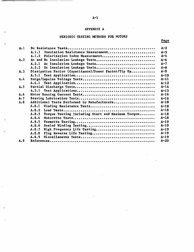
A-1
APPENDIX A
PERIODIC TESTING METHODS FOR MOTORSage
A.1 Dc Resistance Tests ............... ............. ........... . A-2A.1.1 Insulation Resistance Measurement ........................ A-3A.1.2 Polarization Index Measurement.. ................. ............ A-4
A.2 Ac and Dc Insulation Leakage Tests ........... .......... ............. A-6A.2.1 Ac Insulation Leakage Tests .......................... .... A-7A.2.2 Dc Insulation Leakage Tests................ .............. A-8
A.3 Dissipation Factor (Capacitance)/Power Factor/Tip Up ............ A-9A.3.1 Test Application ............... ..** .................. ..*** ...... ... A-10
A.4 Surge/Impulse Voltage Tests ................O............... ........ A-11A.4.1 Test Application ....... ............................... O....*............. A-12
A.5 Partial Discharge Tests..... .................... *........... A-14A.5.1 Test Applications. ... oo ........................ 0.-0.0-0.............. A-15
A.6 Motor Running Current Tests............ ......................... A-16Ao7 Bearing Lubrication Tests ...... ............... ........ . .. . . . . . . A-16A.8 Additional Tests Performed by Manufacturers... .................. A-18
A.8.1 Winding Resistance Tests........ ........ ..... .... . .......... A-18
A.8o2 Load Tests ........ 00... 0. .0. ...................... 0.... 0 ....-...... A-18A.8.3 Torque Testing Including Start and Maximum Torqueo........ A-18A.8.4 Motorette Tests... ....... o..... 0... 0..... .. ... 0 ..... ................................... A-18A.8.5 Formette Testing, .........-............. ..... o. .o .... oo. o. .... o .- *.... A-19A.8.6 Sealed Winding Testing............. . . . o . . . o . .. ....... . A-19A.8.7 High Frequency Life Testing..........................o.... A-19A.8.8 Plug Reverse Life Testing.................so............. .Al19A.8.9 Miscellaneous Tests........ . ..... . . o........ . . . ......... . A-19
A.9 References........................... .......- o-...... o.o.o.- ...... o... oe........................ A-20
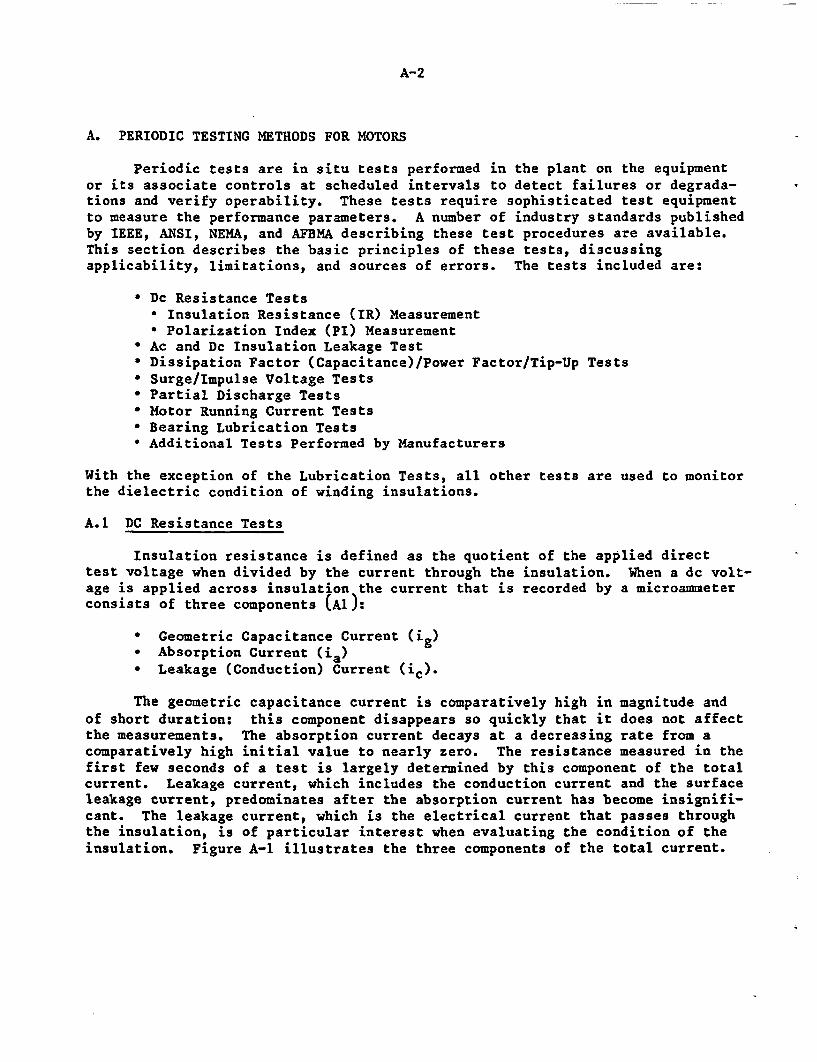
A-2
A. PERIODIC TESTING METHODS FOR MOTORS
Periodic tests are in situ tests performed in the plant on the equipmentor its associate controls at scheduled intervals to detect failures or degrada-tions and verify operability. These tests require sophisticated test equipmentto measure the performance parameters. A number of industry standards publishedby IEEE, ANSI, NEMA, and AFBMA describing these test procedures are available.This section describes the basic principles of these tests, discussingapplicability, limitations, and sources of errors. The tests included are:
* Dc Resistance Tests* Insulation Resistance (IR) Measurement* Polarization Index (PI) Measurement
* Ac and Dc Insulation Leakage Test* Dissipation Factor (Capacitance)/Power Factor/Tip-Up Tests* Surge/Impulse Voltage Tests* Partial Discharge Tests* Motor Running Current Tests* Bearing Lubrication Tests* Additional Tests Performed by Manufacturers
With the exception of the Lubrication Tests, all other tests are used to monitorthe dielectric condition of winding insulations.
A.1 DC Resistance Tests
Insulation resistance is defined as the quotient of the applied directtest voltage when divided by the current through the insulation. When a dc volt-age is applied across insulation the current that is recorded by a microammeterconsists of three components (Al):
* Geometric Capacitance Current (ig)* Absorption Current (ia)* Leakage (Conduction) Current (ic).
The geometric capacitance current is comparatively high in magnitude andof short duration: this component disappears so quickly that it does not affectthe measurements. The absorption current decays at a decreasing rate from acomparatively high initial value to nearly zero. The resistance measured in thefirst few seconds of a test is largely determined by this component of the totalcurrent. Leakage current, which includes the conduction current and the surfaceleakage current, predominates after the absorption current has become insignifi-cant. The leakage current, which is the electrical current that passes throughthe insulation, is of particular interest when evaluating the condition of theinsulation. Figure A-1 illustrates the three components of the total current.
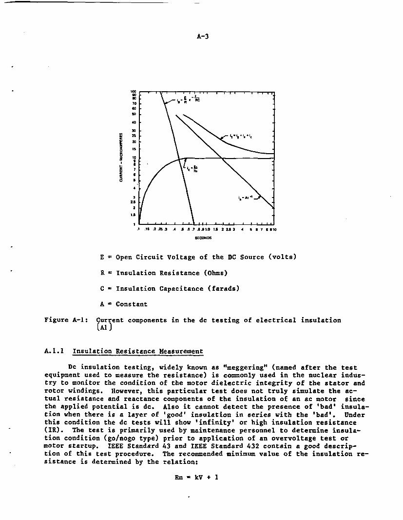
A-3
100
I0 . \\
so RC70 I Rs050
40
30
00i s 2
E
(Al)
~2o a5
z RS65
4
32.5
2
.1 .15 .2 .25~ A .5 .S .? A l.0 1.5 2 LS3 4 5 5 713 10
SECONDS
E = Open Circuit Voltage of the DC Source (volts)
R = Insulation Resistance (ohms)
C =insulation Capacitance (farads)
A - Constant
Figure A-i: Current components in the dc testing of electrical insulation
(Al)
A.1.1 Insulation Resistance Measurement
Dc insulation testing, widely known as "'meggering" (named after the testequipment used to measure the resistance) is commonly used in the nuclear indus-try to monitor the condition of the motor dielectric integrity of the stator and
rotor windings. However, this particular test does not truly simulate the ac-tual resistance and reactance components of the insulation of an ac motor sincethe applied potential is dc. Also it cannot detect the presence of 'bad' insula-tion when there is a layer of 'good' insulation in series with the 'bad'. Underthis condition the dc tests will show 'infinity' or high insulation resistanceCIR). The test is primarily used by maintenance personnel to determine insula-tion condition (go/nogo type) prior to application of an overvoltage test ormotor startup. IEEE Standard 43 and IEEE Standard 432 contain a good descrip-tion of this test procedure. The recommended minimum value of the insulation re-sistance is determined by the relation:
Rm - kV + 1
A-4
where
Rm - recommended minimum insulation resistance in megohms at 400C
kV - rated machine terminal to terminal potential, in rms kilovolts.
A.1.2 Polarization Index Measurement
The polarization index (PI) is a dc insulation resistance test that isperformed on both random wound and form wound motors and is a standard test usedby many utilities in their maintenance programs. It is usually performed on thewindings of a motor stator by taking insulation resistance readings at oneminute intervals up to and including 10 minutes, using a 500, 1,000, 2,500 or5,000 dc volt source such as a megger. The largest test voltage level is lim-ited by 1.7 times the 125 to 150 percent of the rated terminal voltage of themotor being tested. The ratio of the 10 minute to 1 minute resistance readingsgives the polarization index. It is assumed that a fairly steady value of theinsulation resistance is reached in 10 to 20 minutes. This measurement is use-ful in appraising the winding dryness and its fitness to perform other high po-tential tests. The recommended minimum values of polarization index given inthe IEEE standard 43 are:
For Class A insulation 1.5
For Class B insulation 2.0
For Class F insulation 2.0
For certain conditions when the charging current dissipates rapidly, theinsulation resistance (IR) is above the basic minimum requirements, but the PIis below the recommended value. A very high PI value (>6) indicates the insula-tion condition to be brittle and dry, thereby indicating loss of mechanicalstrength. According to the IEEE Standard 43, motors rated at 10,000 kVA andless should have either a value of the PI or IR (at 400C) above the minimumrecommended values. The one minute IR reading should generally be above 1,000megohms with good insulation. However, for motors rated above 10,000 kVA, boththe PI and IR should be above the minimum recommended values.
There are many factors which can affect the measured insulation resistanceduring testing. They are:
Insulation Condition - Presence of moisture in the winding would lower theinsulation resistance significantly, thus increasing the leakage current.
Test Potential Magnitude - The measurement of insulation resistance consti-tute a potential test, and must be kept within the rated voltages, particularlyto low voltage motors and motors with imperfections or fractures in theirinsulating systems. Dc insulation tests often are begun at 500 volts to preventstator damage that can be caused by moisture in the insulation. Retesting at1,000 volts, 2,500, and 5,000 volts may then be safely performed. If the IR de-creases significantly with an increase in applied potential, the insulationshould be examined for dirt, moisture, or other contaminants.
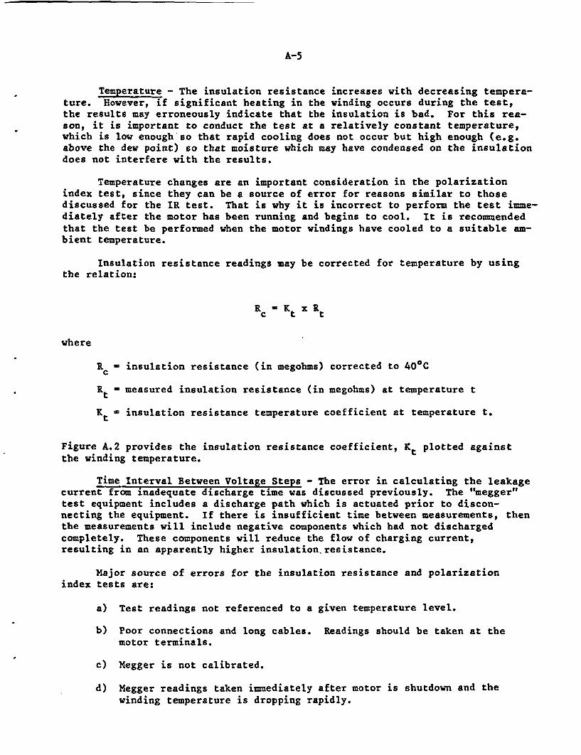
A-5
Temperature - The insulation resistance increases with decreasing tempera-ture. However, if significant heating in the winding occurs during the test,the results may erroneously indicate that the insulation is bad. For this rea-son, it is important to conduct the test at a relatively constant temperature,which is low enough so that rapid cooling does not occur but high enough (e.g.above the dew point) so that moisture which may have condensed on the insulationdoes not interfere with the results.
Temperature changes are an important consideration in the polarizationindex test, since they can be a source of error for reasons similar to thosediscussed for the IR test. That is why it is incorrect to perform the test imme-diately after the motor has been running and begins to cool. It is recommendedthat the test be performed when the motor windings have cooled to a suitable am-bient temperature.
Insulation resistance readings may be corrected for temperature by usingthe relation:
Rc Kt Rt
where
Rc = insulation resistance (in megohms) corrected to 400C
Rt - measured insulation resistance (in megohms) at temperature t
Kt = insulation resistance temperature coefficient at temperature t.
Figure A.2 provides the insulation resistance coefficient, Kt plotted againstthe winding temperature.
Time Interval Between Voltage Steps - The error in calculating the leakagecurrent from inadequate discharge time was discussed previously. The "megger"test equipment includes a discharge path which is actuated prior to discon-necting the equipment. If there is insufficient time between measurements, thenthe measurements will include negative components which had not dischargedcompletely. These components will reduce the flow of charging current,resulting in an apparently higher insulation resistance.
Major source of errors for the insulation resistance and polarizationindex tests are:
a) Test readings not referenced to a given temperature level.
b) Poor connections and long cables. Readings should be taken at themotor terminals.
c) Megger is not calibrated.
d) Megger readings taken immediately after motor is shutdown and thewinding temperature is dropping rapidly.
A-6
100
2Lo
Lu
8
U
X
2
I-0aLu
U,
Ca
so
10
0.5
0.1
0.05
, . , . . . . , , . , . = .. . . . . . . . .. .
i I I F F F I I I I figf 0 r | r { i I o Jo
wer+e+T r +, I l'1 1 1 1 1 E _ _. . r , r . . 5= _
r ' r ' ' i1 , , , r . . , _. r _
I I 1 1. 1 1 1 R _
1- I I I I I I ,/I r =I I I I § I X =
I l l I I SII l =l l l errr =, _ _ _ * 7 _ _ _ _
_ _ _ _ = = = = _ _
= = = = _ T = = = =_ = = _ . = = = =
= = = Z = = l = = = =_ _ / _ = _ l _ _ = =_ _ r _ _ _ 1 _ _ _ __ _ . I i , i . . , _]
= = = I 0 § I I I I |j = = = I I I I I
RZ_ _ I I I § I I__Z = =-
_ _ 1 1 1 1 1 1-1 1'10 0 10 20 30 40 50 60 70 80 90 10o
WINOING TEMPERATURE, OEGREES CELSIUS
Figure A.2: Approximate insulation resistance variation with temperature forrotating machines
e) The winding must be completely discharged from all residual chargesprior to the insulation testings.
A.2 Ac and Dc Insulation Leakage Tests
The cost and reliability of certain motor sizes warrant nondestructivetests to detect a localized fault in the insulation which has high capacitance.The insulating system is a large sheet of surface area separating the copper con-ductors on one side from the iron stator core on the other. Because of this ar-rangement, any measurement made when a test voltage is applied between copperand iron will be indicative of the average characteristics of the entire insula-tion. If there is excessive deterioration in a small portion of the insulation,the contribution of the deteriorated part to the total measurement would be sosmall that it might go undetected.
Ac and dc leakage tests are high-potential (hi pot) tests and have pr vedeffective in finding localized faults in a high-capacitance test object (nj.However, the tests have several shortcomings. Since the voltage level and thetime of application is entirely arbitrary, when an insulation has passed thetest there always remains a question of whether it would have failed had thevoltage been slightly higher or the duration of the test a few seconds longer.
A-7
When the insulation fails during a test, there is a problem in repairing thedamage before the motor can be returned to service. Testing therefore is notrecommended for regular use in preventive maintenance of all size motors. IEEEStandards 95, 432 and 433 contain good descriptions of this test procedure.
The distribution of the voltage gradients (electrical stresses) within theinsulating material is not the same when a dc test voltage is applied comparedto an ac voltage. Although service conditions are more closely duplicated whenan ac voltage is applied to ac motors, the dc test equipment is small, compact,and provides a more economical test. For these reasons dc voltage testing oflarge motors is used more often after installation. The ac high voltage testusually is used to check test voltages with the windings connected to the testcircuit to evaluate possible distortion or peaking of the voltage wave.
Both ac and dc tests generally are conducted on a withstand basis, withvoltage applied for one minute. If no failure or sign of undue stress (e.g.rapid lowering of insulation resistance) is observed, the insulation isconsidered as having passed the test. Measurements of insulation characteris-tics (dielectric loss, power factor, leakage current, insulation resistance) canbe made in conjunction with ac or dc hi pot tests. These values are helpful ininterpreting the results of periodic tests. Some of these tests are discussedin the later sections.
Voltages for routine maintenance tests generally range from 125 to 150%rated terminal voltage for ac tests, and 1.7 times this value for dc tests. The1.7 factor is an attempt to provide a direct potential corresponding, to thepeak alternating value.
A.2.l Ac Insulation Leakage Tests
The ac leakage test is a proof test in which a potential is placed acrossthe insulation to insure a minimum dielectric strength. Because of the risk ofdestroying the insulation, the test voltages for hi-potting motors where the con-dition of the insulation is unknown should not exceed between 125 to 150 percentof the line to line voltage. Ac tests, in general, have a larger risk ofcausing permanent damage to the insulation. The degradation process from the actest is rapid and is caused by the accumulated damage in the insulation fromelectrical discharges. The displacement of charges/dipoles in the insulationcontributes to its deterioration by causing the temperature to rise. These deg-radation processes are directly related to the frequency of the applied voltage.
The ac high potential test is most commonly used in motor manufacturingand in service shops after rewinding or reconditioning stator windings. Forrewound and new motors a test voltage is used of two times rated voltage plus1,000 volts. For reconditioned motors, the high potential test voltage rangesfrom 66 to 75 percent of the test voltages. Ac high potential test equipment isavailable for test voltage from 1,000 volts and up; ac high potential tests arenot used in maintenance because they are potentially destructive.
The ac test for observing the discharge leakage from corona uses specialcorona discharge test equipment. The test is used by manufacturers developingnew insulation systems. In the following paragraphs, the procedures arediscussed for ac insulation leakage tests used in the manufacturing of both ran-dom and form wound motors.
A-8
Random Wound Motors - After the stator is inserted and connected, but beforevarnish treatment, the stator is hi-potted with an ac high potential tester.The motor is tested from the lead or leads to ground, and, as an example, a 2,500volt ac source may be used for 460 volt motor.
After the stator varnish is treated and assembled, the motor is testedfrom a lead or leads to ground with a maximum voltage of two times rated voltageplus 1,000.
Form Wound Motors - After form wound coils are insulated, each coil can beac high-pot tested. Some manufacturers do not hi-pot the coils at this point,while others test 100% of the coils. Another approach is to test a sample ofthe coils and then, if any failures are found, conduct a 100% inspection.
After the coils are inserted in the stator but not connected or treatedwith varnish, all the coils are hi-potted at a voltage below the value used onthe coils individually and well above the final NEMA hi-pot test of two timesrated voltage plus 1,000.
After the stator is connected and before varnish treatment, the stator ishi-potted from a lead or leads to ground at a voltage below that given in theabove paragraph but above that for the final high potential test.
After the stator has been varnished and assembled in the complete motor,it is hi-potted from a lead or leads to ground at the NEMA rated votage of twotimes rated voltage plus 1,000.
A.2.2 Dc Insulation Leakage Tests
The current which is measured in the dc high voltage test circuit includesleakage or conduction current, and also the current necessary to charge the insu-lation to the desired test voltage. The source of the direct test voltage usu-ally has appreciable resistance to reduce the risk of damage due to charging cur-rent. Sudden change in voltage produce larger charging or discharging currentsas compared to the conduction current component. This current, also known as di-electric absorption current, becomes insignificant 10 to 20 minutes after the po-tential is applied.
The dc hi pot test is usually conducted on a withstand basis. However, itis prudent to record the resistance-versus-voltage or current-versus-voltagecharacteristics of motor insulation. Plots from this data serve as a referencefor analysis of subsequent tests.
Current measurements made during a test with dc voltage will give an indi-cation of impending breakdown, so that the test can be discontinued. However,other unpredicted breakdowns could occur and may not be detected from the cur-rent readings.
The high voltage dc step voltage test for insulation leakage is ordinarilyperformed on large motors, and is used in plant maintenance programs and bymotor manufacturers when there is a special request by the customer. The testinvolves applying increasing dc voltage steps to a stator. The leakage currentsat each step are recorded after waiting for the discharge currents to stop. Thestable current is the leakage current through the insulation. Obtaining a
A-9
steady current may take an excessively long time. Therefore, it may be neces-sary to use special test equipment or microprocessors that calculate the leakagecurrents, or to manually calculate the leakage currents by mathematical summa-tion. The test is continued until the maximum test voltage level is reached.The leakage currents are plotted against the voltage to determine the tip-up(which is the difference between the final current reading and the initial cur-rent reading). The test is performed by using special step voltage testerswhich allow increasing voltage to be applied and the resulting current measured.The test procedure is discussed in detail in IEEE Standard 95 and IEEE Standard432.
The major sources of in the error measurement are the same as those forthe ac insulation test. Excessive voltages can increase the risk of damagingthe insulation, just as with the ac insulation leakage test.
A.3 Dissipation Factor (and Capacitance)/Power Factor/Tip Up
When an ac potential is applied to a winding, alternating current flowsthrough the stator and reaches a steady state value immediately after the appli-cation. Therefore, time is not considered as a factor in ac measurements and,unlike dc tests, measurements may be made very rapidly. Because of the alternat-ing nature of the test voltage, the current that flows is largely charging cur-rent, which is a function of the capacitance of the insulation. Howevercapacitance is not very sensitive to insulation condition, and degraded insula-tion usually is reflected in dielectric loss which is determined from the losscomponent of the total current measured (see in Figure A-3).
The power factor is a measure of the energy lost in the insulation (inwatts) through I R (heat) losses and can be expressed as,
Power Factor =Resistive CurrentTotal Measured Charging Current
The power factor is almost identical to the dissipation factor for low valuesand is related to it by the expression,
Power Factor Dissipation Factorl+(Dissipation Factor)2
The power factor is a measure of the overall condition of the insulation and isusually performed on large, high voltage machines of 6kV, and higher. Highpower factors are generally indicative of high porosity, delamination,improperly or incompletely cured polymers. As the polymer ages and chemical deg-radation occurs (oxidation and loss of volatiles by ionization loss), voids formin the polymer which permit greater electrical leakage and the power factor willincrease. The use of power factor to evaluate the condition of the insulationhas the advantage that it is independent of the machine rating or dimension.
In a perfect insulation material, the power factor would be expected to re-main constant with the increasing test voltage. However, all insulation has im-
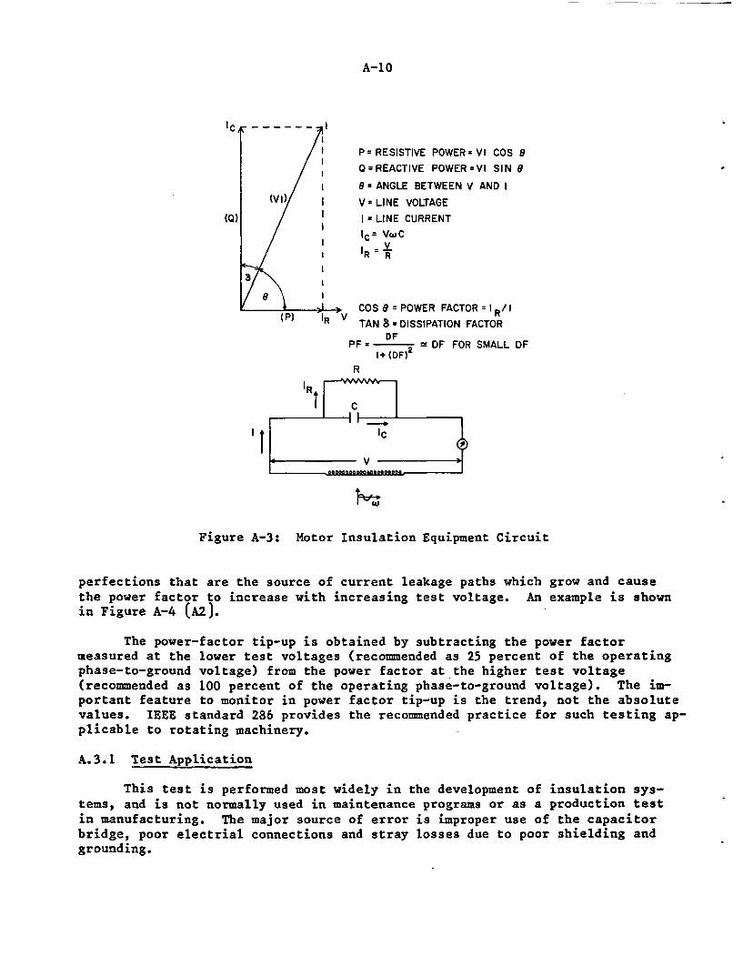
A-10
/I P RESISTIVE POWER- VI COS 9
O=REACTIVE POWER=VI SIN 3/ = ANGLE BETWEEN V AND I
(VI) V - LINE VOLTAGE
(Q) I = LINE CURRENT
/ I IC= VWC=z V(I
I I R R
9 ICOS 8 = POWER FACTOR 1 R/ I
(P) 'R V TAN 8 = DISSIPATION FACTOR
DFPF = 2 DF FOR SMALL DF
l+ (DF)R
IR
'~IC
Figure A-3: Motor Insulation Equipment Circuit
perfections that are the source of current leakage paths which grow and causethe power factor to increase with increasing test voltage. An example is shownin Figure A-4 (A2).
The power-factor tip-up is obtained by subtracting the power factormeasured at the lower test voltages (recommended as 25 percent of the operatingphase-to-ground voltage) from the power factor at the higher test voltage(recommended as 100 percent of the operating phase-to-ground voltage). The im-portant feature to monitor in power factor tip-up is the trend, not the absolutevalues. IEEE standard 286 provides the recommended practice for such testing ap-plicable to rotating machinery.
A.3.1 Test Application
This test is performed most widely in the development of insulation sys-tems, and is not normally used in maintenance programs or as a production testin manufacturing. The major source of error is improper use of the capacitorbridge, poor electrial connections and stray losses due to poor shielding andgrounding.
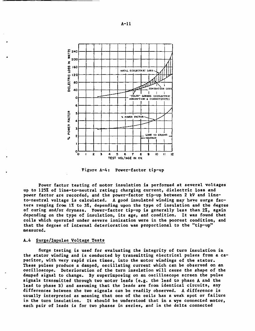
A-1l
CnI.-
9n10
Uw1-IW5
_ _
240 i - - - - - - -I-20C0 - -
160 - - - - - -
TOTAL DIELECTRIC LOSS
120C
c040 _ _ _ IONIATION LOSS
"SOLID" LOSSES (DIELECTRIC6_ ABSORPTION CONDUCTIVITY)
6
_ ___ _ X IPOWER AC41R-_ /
4--
2 LIKE TO GROUNDVOLTAGE
It0
I-U.
I'-
W
0
0~
O 1 2 3 4 5 6 7 6TEST VOLTAGE IN KV.
9 10 If 12
Figure A-4: Power-factor tip-up
Power factor testing of motor insulation is performed at several voltagesup to 125% of line-to-neutral rating; charging current, dielectric loss andpower factor are recorded, and the power-factor tip-up between 2 kV and line-to-neutral voltage is calculated. A good insulated winding may have surge fac-tors ranging from 1Z to 3%, depending upon the type of insulation and the degreeof curing and/or dryness. Power-factor tip-up is generally less than 2%, againdepending on the type of insulation, its age, and condition. It was found thatcoils which operated under severe ionization were in the poorest condition, andthat the degree of internal deterioration was proportional to the "tip-up"measured.
A.4 Surge/Impulse Voltage Tests
Surge testing is used for evaluating the integrity of turn insulation inthe stator winding and is conducted by transmitting electrical pulses from a ca-pacitor, with very rapid rise times, into the motor windings of the stator.These pulses produce a damped, oscillating current which can be observed on anoscilloscope. Deterioration of the turn insulation will cause the shape of thedamped signal to change. By superimposing on an oscilloscope screen the pulsesignals transmitted through two motor leads (e.g. the lead to phase A and thelead to phase B) and assuming that the leads are from identical circuits, anydifferences between the two signals can be readily observed. A difference isusually interpreted as meaning that one of the coils has a weak spot or failurein the turn insulation. It should be understood that in a wye connected motor,each pair of leads is for two phases in series, and in the delta connected
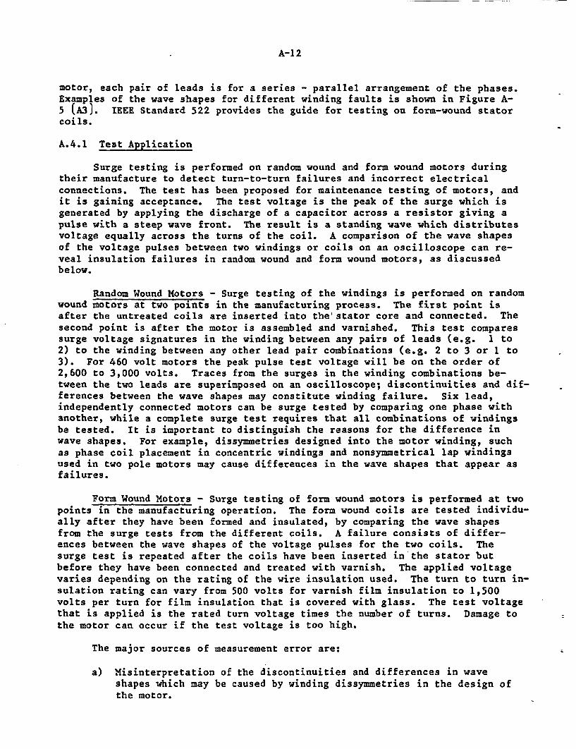
A-1 2
motor, each pair of leads is for a series - parallel arrangement of the phases.Examples of the wave shapes for different winding faults is shown in Figure A-5 (A3). IEEE Standard 522 provides the guide for testing on form-wound statorcoils.
A.4.1 Test Application
Surge testing is performed on random wound and form wound motors duringtheir manufacture to detect turn-to-turn failures and incorrect electricalconnections. The test has been proposed for maintenance testing of motors, andit is gaining acceptance. The test voltage is the peak of the surge which isgenerated by applying the discharge of a capacitor across a resistor giving apulse with a steep wave front. The result is a standing wave which distributesvoltage equally across the turns of the coil. A comparison of the wave shapesof the voltage pulses between two windings or coils on an oscilloscope can re-veal insulation failures in random wound and form wound motors, as discussedbelow.
Random Wound Motors - Surge testing of the windings is performed on randomwound motors at two points in the manufacturing process. The first point isafter the untreated coils are inserted into the' stator core and connected. Thesecond point is after the motor is assembled and varnished. This test comparessurge voltage signatures in the winding between any pairs of leads (e.g. 1 to2) to the winding between any other lead pair combinations (e.g. 2 to 3 or 1 to3). For 460 volt motors the peak pulse test voltage will be on the order of2,600 to 3,000 volts. Traces from the surges in the winding combinations be-tween the two leads are superimposed on an oscilloscope; discontinuities and dif-ferences between the wave shapes may constitute winding failure. Six lead,independently connected motors can be surge tested by comparing one phase withanother, while a complete surge test requires that all combinations of windingsbe tested. It is important to distinguish the reasons for the difference inwave shapes. For example, dissymmetries designed into the motor winding, suchas phase coil placement in concentric windings and nonsymmetrical lap windingsused in two pole motors may cause differences in the wave shapes that appear asfailures.
Form Wound Motors - Surge testing of form wound motors is performed at twopoints in the manufacturing operation. The form wound coils are tested individu-ally after they have been formed and insulated, by comparing the wave shapesfrom the surge tests from the different coils. A failure consists of differ-ences between the wave shapes of the voltage pulses for the two coils. Thesurge test is repeated after the coils have been inserted in the stator butbefore they have been connected and treated with varnish. The applied voltagevaries depending on the rating of the wire insulation used. The turn to turn in-sulation rating can vary from 500 volts for varnish film insulation to 1,500volts per turn for film insulation that is covered with glass. The test voltagethat is applied is the rated turn voltage times the number of turns. Damage tothe motor can occur if the test voltage is too high.
The major sources of measurement error are:
a) Misinterpretation of the discontinuities and differences in waveshapes which may be caused by winding dissymmetries in the design ofthe motor.
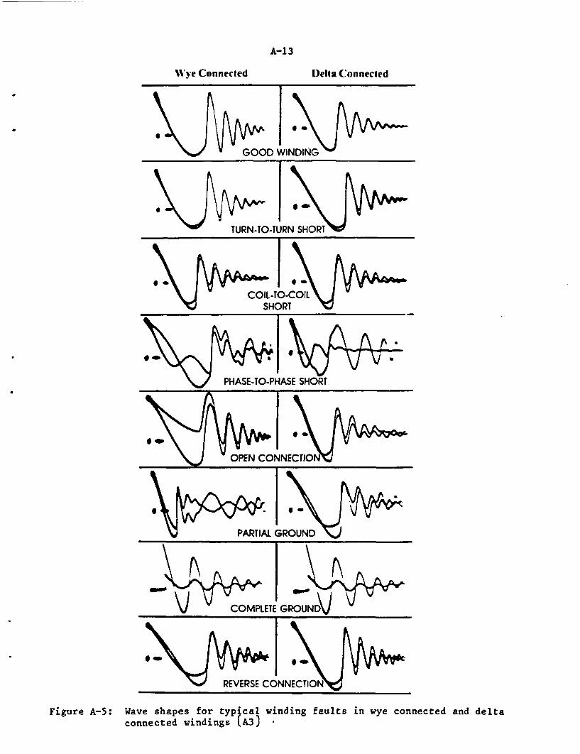
A-1 3
Wy'ye Connected Della Connected
04
GOOD WINDING
T STURN-TO-TURN SHOR
i
REVERSE CONNECTIO
Figure A-5: Wave shapes for typical winding faults in wye connected and deltaconnected windings (A3) -
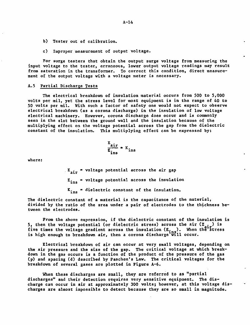
A-14
b) Tester out of calibration.
c) Improper measurement of output voltage.
For surge testers that obtain the output surge voltage from measuring theinput voltage to the tester, erroneous, lower output voltage readings may resultfrom saturation in the transformer. To correct this condition, direct measure-ment of the output voltage with a voltage meter is necessary.
A.5 Partial Discharge Tests
The electrical breakdown of insulation material occurs from 500 to 5,000volts per mil, yet the stress level for most equipment is in the range of 40 to50 volts per mil. With such a factor of safety one would not expect to observeelectrical breakdown (as a corona discharge) in the insulation of low voltageelectrical machinery. However, corona discharge does occur and is commonlyseen in the slot between the ground wall and the insulation because of themultiplying effect on the voltage potential across the gap from the dielectricconstant of the insulation. This multiplying effect can be expressed by:
E .air
E. insins
where:
E air = voltage potential across the air gap
Ein = voltage potential across the insulation
K. - dielectric constant of the insulation.ins
The dielectric constant of a material is the capacitance of the material,divided by the ratio of the area under a pair of electrodes to the thickness be-tween the electrodes.
From the above expression, if the dielectric constant of the insulation is5, then the voltage potential (or dielectric stress) across the air (E air ) isfive times the voltage gradient across the insulation (E. ). When the stressis high enough to breakdown air, then a corona discharge will occur.
Electrical breakdown of air can occur at very small voltages, depending onthe air pressure and the size of the gap. The critical voltage at which break-down in the gas occurs is a function of the product of the pressure of the gas(p) and spacing (d) described by Paschen's Law. The critical voltages for thebreakdown of several gases are plotted in Figure A-6.
When these discharges are small, they are referred to as "partialdischarges" and their detection requires very sensitive equipment. The dis-charge can occur in air at approximately 300 volts; however, at this voltage dis-charges are almost impossible to detect because they are so small in magnitude.
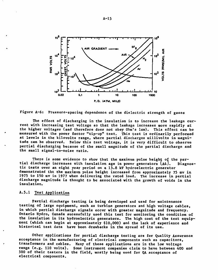
A-15
105 10'
A . IR GRADIENT S- e
102 e-A
00
0.02 0.1 1 la 100 lo0
P.D. IATM. MMlS)
Figure A-6: Pressure-spacing dependence of the dielectric strength of gases
The effect of discharging in the insulation is to increase the leakage cur-rent with increasing test voltage so that the leakage increases more rapidly atthe higher voltages (and therefore does not obey Ohm's law). This effect can bemeasured with the power factor "tip-up" test. This test is ordinarily performedat levels in the kilovolts range, where partial discharges millivolts in magni-tude can be observed. Below this test voltage, it is very difficult to observepartial discharging because of the small magnitude of the partial discharge andthe small signal-to-noise ratio.
There is some evidence to show that the maximum pulse height of the par-tial discharge increases with insulation age in power generators LA4J. Diagnos-tic tests over an eight year period on a 13.8 kV hydroelectric generatordemonstrated tht the maximum pulse height increased from approximately 75 mv in1975 to 150 mv in 1977 when delivering the rated load. The increase in partialdischarge magnitude is thought to be associated with the growth of voids in theinsulation.
A.5.1 Test Application
Partial discharge testing is being developed and used for maintenancetesting of large equipment, such as turbine generators and high voltage cables,in which partial discharge signals occur with greater magnitude and frequency.Ontario Hydro, Canada sucessfully used this test for monitoring the condition ofthe insulation in its hydroelectric generators. The high cost of the test equip-ment (which can begin at approximately $10,000) and the lack of experience andhistorical test data have been drawbacks in the spread of its use.
Other applications for partial discharge testing are for Quality Assuranceacceptance in the manufacturing of electrical components such as capacitors,transformers and cables. Many of these applications are in the low voltagerange (e.g. 110 volts). Some instrument companies claim to have between 400 and500 of their testers in the field, mostly being used for QA acceptance ofelectrical components.
A-16
A.6 Motor Running Current Tests
An increase in the motor running current can be caused by excessive loadson the motor (e.g., from tightly packed stem packing, worn bearings, bent valvestem), by unbalanced voltage in the phase windings and from deterioration of thewinding insulation and low full-load voltage. The result increases in such cur-rents can be a rise in temperature of the motor and accelerated thermal degrada-tion of the winding insulation.
Motor running currents normally should be below the service factor, whichcan be 1.15, or 15 per cent above the rated value. All large motors (greaterthan 500 hp) and totally enclosed motors normally have a unity service factor.Recording and trending the motor running current can be useful in confirmingother test results, in assessing the condition of the motor and predictingwhether it will remain functional.
The terminal voltage should be measured to help to diagnose the reason forany changes in the motor running current, specifically, whether an increase re-sults from a reduction in the input voltage or from unbalanced motor phasevoltages.
Both the no-load and the load currents are measured during manufacturingand on the assembled motor. The test also is performed in the maintenance pro-grams at the utilities for checking the load and balance of phase currents. Theno load test is performed on the assembled motor in conjunction with the imped-ance test and open rotor bar test. The no load current test and impedance testare part of the National Electrical Manufacturers Association (NEMA) commercialtest in NEMA MG-1, "IEEE Standard Test Procedure for Polyphase Induction Motorsand Generators."
The no load test is performed at the rated voltage to obtain the motor cur-rent and current balance in the phases. The impedance current of the motor ismeasured at one quarter of the rated voltage with the rotor locked. The openbar test is performed with a single phase voltage applied to the motor and openbars are detected by irregular current readings on the unlocked rotor when therotor is slowly turned by hand. These tests are described in IEEE Standard 112.
A.7 Bearing Lubrication Tests
When the motor is assembled, the bearings are lubricated either withgrease or oil. During shipping, the oil is removed from the motor and must bereplaced before the motor is stored or installed. During operation the lubri-cant should be replaced in intervals recommended by the manufacturer. Greaselife depends on the bearing size, speed, load and temperature. An equation forbearing grease life is (A5J:
log L - -2.60 + 4,420/(460 + T) - 0.301Swhere:
A-1 7
L = time at which 10% of greased bearings fail (hours)
T = bearing temperature (0F)
S = half-life reduction factor and is the sum of the reduction factorsfor grease type, bearing speed (SN) and bearing load (S )
The grease type reduction factor can be determined from a rating given byBooser (A5J. This factor varies between 0 for long-life petroleum and siliconegreases to 2.9 for diester, low-temperature greases.
The bearing speed reduction factor, SN can be calculated from the expres-sion:
S= 0.86DN/(DN)L
where:
D - shaft diameter at bearing seat (mm)
N = speed (rpm)
(DN)L = limiting DN for a particular bearing type (mm-rpm)
The bearing load reduction factor, Sw can be calculated from the expres-sion:
SW = 0.61DNW/C2
where:
W = radial load (lb)
C = specific dynamic capacity (lb) which is the bearing load that producedfatigue failure in 10% of the bearings after 1 million revolutions.
Generally, regreasing should be done at or before the calculated 10%grease life (L). Large motors that use oil for lubrications should be tested pe-riodically for metal wear and oil contaminations in the bearings, thuspreventing any catastrophic failures.
Oil Analysis - The three significant lubrication variables affecting gear(or bearing) life are: viscosity, acid number (pH) and antioxidant concegtrg-tion. These can be evaluated with the following standards: ASTM D88-53 LA6J,ASTM D974-53T (A7), and D664-52 and ASTM D943-53T (A8), respectively.
Visual inspection of the oil for particulates (e.g. metal shavings, etc.)and identification of the metal to localize the source of wear can provide somemeasure of bearing degradation.
A-18
A.8 Additional Motor Tests Performed by Manufacturers
A.8.1 Winding Resistance Tests
The winding resistance test is used in the maintenance, manufacturing andrewinding of motors. The test is performed after the stator is wound andconnected but it is being varnished.
This test determines electrical unbalance in the windings and if thewindings have the proper resistance. Improper resistance can result from the in-correct values for the number of turns, pitch, wire size and connection (e.g.wye or delta). The test is normally performed with a resistance bridge to mea-sure the resistance of the winding between leads (e.g. between lead 1 and lead2, lead 2 and lead 3 and lead 1 and lead 3); the measurement then is comparedwith the design limits.
The winding resistance balance between phases can be inspected only onsix-lead motors by measuring the resistance between each pair of leads (e.g.lead 1 and lead 4, lead 2 and lead 5, etc.).
Winding resistance is measured on random wound and form wound motors dur-ing manufacturing and during maintenance. However, the winding resistance ofform wound motors is much smaller than of random wound motors (because of thelarger cross-section of the form wound coils) and the small number of turns.
The major sources of error in measurement are due to the resistance bridgebeing out of calibration and poor electrical connections between the coil leadsand test set.
A.8.2 Load Tests
These tests determine the efficiency, power factor, temperature rise, linecurrents and watts at different loads to verify the motor design parameter andare described in IEEE Standard 112-1978. These tests also can be used to evalu-ate the performance of driven equipment by comparing the equipment performance(e.g. flow rate for a pump) with the electrical load on the motor. In many ap-plications only the load current is monitored.
A.8.3 Torque Testing Including Start and Maximum Torque
This test measures the motor torque and current to verify the motor designparameters. The tests are discussed in IEEE Standard 112-1978.
A.8.4 Motorette Tests
This test is for determining the insulation life for random wound motorsusing models of the insulation system called motorettes. The test is conductedas IEEE Standard 117-1974, "Test Procedure for Evaluation of Systems ofInsulating Materials for Random Wound Electric Machinery." The motorettes arecycled to failure by repeatedly heating them in an oven to age them and bysubjecting them to vibration and humidity stresses. The criterion of failure isa short circuit from failure in the turn-to-turn, phase-to-phase or phase-to-ground insulation. Using of IEEE Standard 101, "IEEE Guide to Statistical Anal-
A-19
ysis of Thermal Life Test Data," the data from the test can be plotted andanalyzed.
A.8.5 Formette Testing
This test is for determining the insulation life for form wound motorsusing models of the insulation system called formettes. The test is conductedper IEEE 275-1966, "Test Procedures for Evaluating of Systems of Insulating Mate-rials for AC Electrical Machinery Employing Form Wound Preinsulated StatorCoils." This test is conducted in a manner similiar to that given in IEEE Stan-dard 117-1974 and the test data is plotted and analyzed as described in IEEEStandard 100.
A.8.6 Sealed Winding Testing
This test is conducted per IEEE Standard 429-1972, "IEEE Standard Test Pro-cedure Evaluation of Sealed Insulation Systems for AC Electrical MachineryEmploying Form Wound Stator Coils." It is similar to the test in IEEE Standard275-1966 except an underwater submergence test is used in place of the humiditytest. The results are plotted and analyzed as discussed above for the IEEEstandards.
A.8.7 High Frequency Life Testing
This test determines insulation life generally in form wound motors. Itrequires that the accelerated aging of the motors be performed while applyingvoltages on the order of 3,000 cycles per second.
A.8.8 Plug Reverse Life Testing, Holding Temperature Constant
In this test the motor is started in one direction, run for a period ofseconds and then the leads are interchanged (e.g. the lead for phase A becomesthe lead for phase B, etc.), reversing the rotation of the motor. The processis repeated until motor failure occurs. In this way the motor is thermally andoperationally aged. The test is conducted to determine the adequacy of themotor winding bracing system over the life of the motor, and can be combinedwith a 100% relative humidity test to determine the life of sealed windingmotors.
A.8.9 Miscellaneous Tests
The twisted wire test is an easy but not very functional way for screeningand classifying insulated magnet wire according to its temperature class. Thetest consists of subjecting pairs of insulated magnet wires to voltage stressingand thermal aging cycles and conducting insulation tests to determine when insu-lation failure occurs.
The twisted wire test was originally described in IEEE Standard 57 whichno longer exists and is presently described in ASTM D2307, "Test for RelativeThermal Endurance of Film Insulated Magnet Wire." IEEE Standard 117, "StandardTest Procedure for Evaluation of Systems of Insulating Materials for Random-Wound AC Electrical Machinery" is a more functional test than the twisted wiretest. The twisted wire test, ASTMD2307 is referred to in Underwriters Labora-tory Standard UL 1446, "Systems of Insulating Materials". Another standard that
A-20
references the twisted wire test is ANSI/NEMA Standard MW1000, "Magnet Wire," inwhich the procedures for preparing the specimens are given and minimum accept-able test values are specified.
The humidity test is conducted on motor stators or models of stators byselected tests (e.g. current leakage, phase balance, dissipation factor andcapacitance measurements and corona starting voltage) after exposure to mois-ture. The test is described in IEEE Standard 117 as one which includes thermalaging and mechanical stress. The humidity test also is part of the militaryspecification, MIL-M-17060E (SH).
The sealed tube test is used to measure the compatibility of components inan insulation materials system by placing samples of the materials in glasstubes, sealing them and heating the glass tubes. For the hydrolysis test, thetube is sealed with water at a temperature above 1000C to create an environmentwith greater than 95% relative humidity. For the Underwriters Laboratory Stan-dard UL 1446, Section 14, in which water is not added, the test temperature is250C above the rated temperature for the particular insulation system.
The effects of hydrolysis on the polymers is evaluated by measuring thehardness and weight gain at room temperature after the tube is opened at the endof the test.
A.9 References
(Al) Curdts, E.B., "Insulation Testing by D-C Methods," Technical Publication22Tlb, 1984, by Biddle Instruments, Blue Bell, PA.
(A2) Povey, E.H., Rickley, A.L., "Preventive-Maintenance Testing of Genera-tor Insulation," Workshop Proceedings: Rotating Machinery Insulation,EPRI EL-2211, December 1981.
(A3) Bergstrom, A., Smith, G.W., "An Inroduction to the Testing of Insula-tion Systems in Electrical Apparatus," pp. 1-16, issued by Baker Instru-ment Company, Ft. Collins, CO.
(A4) Kurtz, M., Lyles, J.F., "Generator Insulation Diagnostic Testing,"Trans. Power Apparatus and Systems, PAS-98, 5, 1596-1603 (1979).
(A5) Booser, E.R., "When to Grease Bearings," Machine Design, pp. 70-73, August21, 1975.
(A6) "Method for Testing Visocity of Lubricants," American Society for Testingof Materials Standard ASTM D88-53.
(Al) "Methods for Measuring the Acidity of Lubricants," American Society forTesting of Materials Standard ASTM D974-53T.
(A8) "Methods for Measuring Antioxidant Concentrations in Lubricants," AmericanSociety for Testing of Materials Standard ASTM D943-53T.
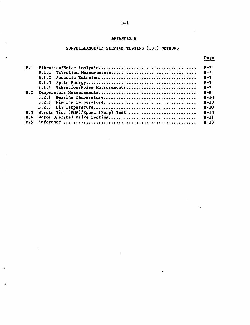
B-1
APPENDIX B
SURVEILLANCE/IN-SERVICE TESTING (UST) METHODS
Page
B.1 Vibration/Noise Analysis ..... ............. ........ B-3B.1.1 Vibration Measurements... ... . ............ . ... ... ....... B-3B.1.2 Acoustic Emission................* ............*. * ...........***......**......***.......... B-7B.1.3 Spike Energy. .......... * .* .* .......................... *es B-7B.1.4 Vibration/Noise Measurements ....... ...... 0-6 ..... *.. B-7
B.2 Temperature Measurements .......... ...... . ...... . ...... .... .. s B-8B.2.1 Bearing Temperature ...... ............ ........... ..... .. B-10B.2.2 Winding Temperature ........ .......................... .... .. B-10B.2.3 Oil Temperature............................ ........... ..... B-10
B.3 Stroke Time (MOV)/Speed (Pump) Test ........................... B-10B.4 Motor Operated Valve Testing .................................... B-liB.5 Reference ........ ........... ............................. ............................. B-13
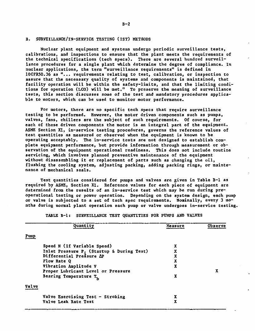
B-2
B. SURVEILLANCE/IN-SERVICE TESTING (IST) METHODS
Nuclear plant equipment and systems undergo periodic surveillance tests,calibrations, and inspections to ensure that the plant meets the requirements ofthe technical specifications (tech specs). There are several hundred surveil-lance procedures for a single plant which determine the degree of compliance. Innuclear applications, the term "surveillance requirements" is defined in10CFR50.36 as "... requirements relating to test, calibration, or inspection toassure that the necessary quality of systems and components is maintained, thatfacility operation will be within the safety-limits, and that the limiting condi-tions for operation (LCO) will be met." To preserve the meaning of surveillancetests, this section discusses some of the test and mandatory procedures applica-ble to motors, which can be used to monitor motor performance.
For motors, there are no specific tech specs that require surveillancetesting to be performed. However, the motor driven components such as pumps,valves, fans, chillers are the subject of such requirements. Of course, foreach of these driven components the motor is an integral part of the equipment.ASME Section XI, in-service testing procedures, governs the reference values oftest quantities as measured or observed when the equipment is known to beoperating acceptably. The in-service tests are not designed to establish com-plete equipment performance, but provide information through measurement or ob-servation of the equipment operational readiness. This does not include routineservicing, which involves planned preventive maintenance of the equipmentwithout disassembling it or replacement of parts such as changing the oil,flushing the cooling system, adjusting packing, adding packing rings, or mainte-nance of mechanical seals.
Test quantities considered for pumps and valves are given in Table B-1 asrequired by ASME, Section XI. Reference values for each piece of equipment aredetermined from the results of an in-service test which may be run during pre-operational testing or power operation. Depending on the system design, each pumpor valve is subjected to a set of tech spec requirements. Nominally, every 3 mo-nths during normal plant operation each pump or valve undergoes in-service testing.
TABLE B-1: SURVEILLANCE TEST QUANTITIES FOR PUMPS AND VALVES
Quantity Measure Observe
PUMP
Speed N (If Variable Speed) XInlet Pressure Pi (Startup & During Test) XDifferential Pressure AP XFlow Rate Q XVibration Amplitude V XProper Lubricant Level or Pressure XBearing Temperature Tb X
Valve
Valve Exercising Test - Stroking XValve Leak Rate Test X
B-3
The test quantities used in surveillance or pumps and valves include vibra-tion amplitudes, temperatures, stroke time for MOVs and speed and flow forpumps. These parameters are also suitable for motor surveillance and arediscussed here. Vibration and noise analysis can be applied to motor mountings,as well as the bearings. The temperature measurements include the winding sys-tem, the bearings and the lubricating oil for large motors, specifically forthose with sleeve bearings. Valve stroking and pump speeds which can betranslated to the motor speed also are discussed. A subsection is devoted onMOV testing which measures several key parameter suitable for inclusion in theplant surveillance testing program.
B.1 Vibration/Noise Analysis
Unusual vibration and noise may occur from different sources in a motor,such as worn bearings, rotor misalignment, and loose parts. Shorted turns inthe winding may induce vibrations in the motor that are out of phase with the 60Hz ac load.
Unusual noise may result from worn bearings, baffles for the cooling airwhich have become detached, and loose mechanical parts. Some noise may be theresult of the motor design, such as a noisy circuit, or because of an unusualducting of air. The discussion below treats the vibration and noise caused bybearings, in more detail.
The objective is to discuss potential test methods for monitoring vibra-tion and noise in the bearings of running motors to detect incipient failures.These tests would be performed on continuous duty large pump motors.
Bearing degradation generally manifests itself by a deterioration of con-tact surfaces. The repeated application of high alternating stresses whichoccur just below the surface can produce small voids. Cracks grow from thevoids to the surface, resulting in pitting. Surface defects also may arise fromsmall oscillations of the balls in the bearings ("false brinelling") during ship-ment. These defects may occur in the inner race, outer race, rollers or balls.
Other possible degradation mechanisms include broken cages, loss of greaseresulting in inadequate lubrication, and brinelling of the bearing from exces-sive loading (permanent deformation of the bearing). Excessive clearances fromloosened lock nuts and excessive bushing shaft seat wear from abrasives in thelubricant are mechanisms that cause bearing degradation.
Degradation can be detected in a variety of ways. Each method capturessome form of energy produced by the defective action on the dynamics of therotating bearing.
B.l.1 Vibration Measurements
As the shaft rotates, various elements of the bearing pass repeatedly overthe surface defects causing in vibration. Figure B-l(a) and (b) show the partsin a cross section of a representative angular contact bearing. By knowing thevibration signature of the bearing, degradation may be detected as the defectgrows and the problem becomes more severe.
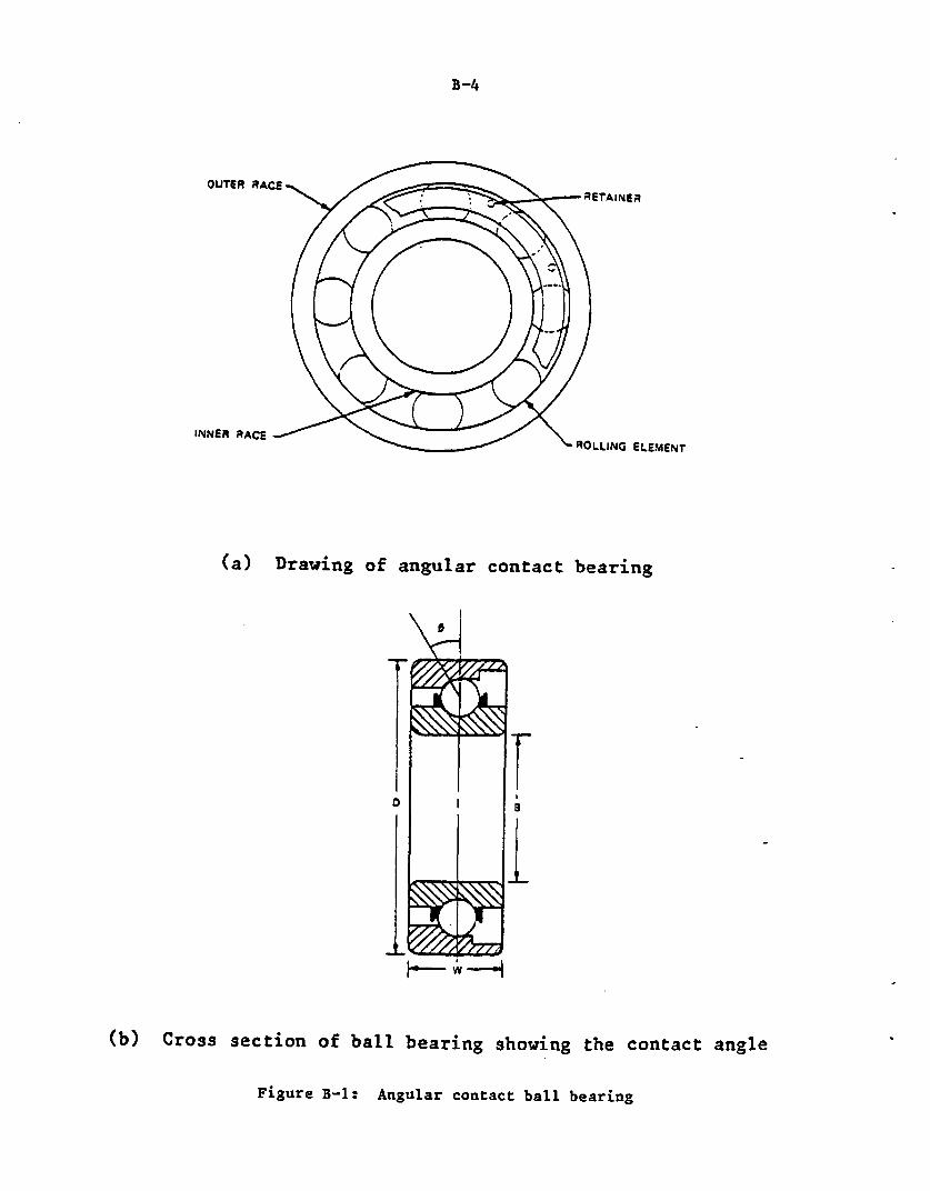
8-4
OUTER RACES
INNER RACE -
- RETAINER
ROLLING ELEMENT
(a) Drawing of angular contact bearing
0 F
(b) Cross section of ball bearing showing the contact angle
Figure B-1: Angular contact ball bearing
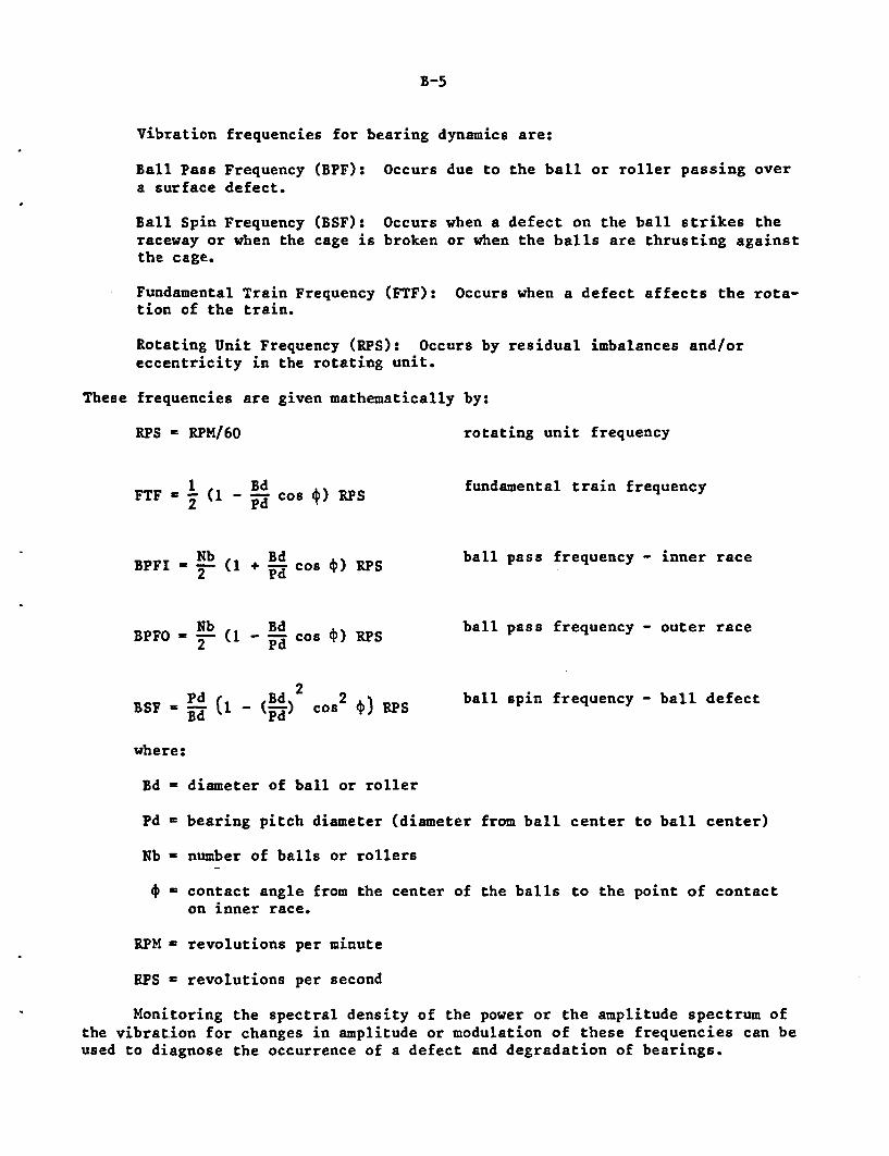
B-5
Vibration frequencies for bearing dynamics are:
Ball Pass Frequency (BPF): Occurs due to the ball or roller passing overa surface defect.
Ball Spin Frequency (BSF): Occurs when a defect on the ball strikes theraceway or when the cage is broken or when the balls are thrusting againstthe cage.
Fundamental Train Frequency (FTF): Occurs when a defect affects the rota-tion of the train.
Rotating Unit Frequency (RPS): Occurs by residual imbalances and/oreccentricity in the rotating unit.
These frequencies are given mathematically by:
RPS - RPM/60 rotating unit frequency
FTF = (1 -d cos *) RPS fundamental train frequency
P Nb (1 dcos ) RPS ball pass frequency - inner race
BPFO = Nb (1 Bd cos RPS ball pass frequency - outer race2 PdCO~JP
= Ed (o (d) s ) ball spin frequency - ball defect
where:
Bd = diameter of ball or roller
Pd = bearing pitch diameter (diameter from ball center to ball center)
Nb - number of balls or rollers
* - contact angle from the center of the balls to the point of contacton inner race.
RPM - revolutions per minute
RPS = revolutions per second
Monitoring the spectral density of the power or the amplitude spectrum ofthe vibration for changes in amplitude or modulation of these frequencies can beused to diagnose the occurrence of a defect and degradation of bearings.
B-6
Defects in bearing raceways would show up as narrow band spikes at theBPFI or BPFO. As the size of the defect increases, the band width of the spec-trum increases and may become modulated by the RPS, i.e., a wide band spectrumwith narrow band spikes at BPF and BPF ± RPS where RPS << BPF.
Ball or roller surface defects produce narrow band spikes at the BSF. Oneball with a defect would appear as a spike at the BSF; multiple defects would ap-pear at Nb x BSF. Should the defects become large, the FTF would also beexcited. A damaged or defective cage also would show up in the BSF, with a se-verely damaged cage exhibiting frequency shifts.
Excessive internal looseness appears in the RPS plus multiples of the RPS.A bearing turning on the shaft or in the housing results in low amplitude,broad-band random noise. inadequate lubrication usually shows as an increase inthe amplitude of peaks in the range of higher frequencies. The locations ofthese peaks are dependent on the geometry and RPS of the bearing, and are typi-cally experimentally determined.
Most bearings have some characteristics at each of these frequencies andtheir spectra are complex as the basic frequencies. Essentially, detectionoccurs through identification of the peak amplitudes, and subsequent monitoringof the changes in these amplitudes with time.
Transducers for vibration measurements fall into three classes:accelerometers, velocity pick-ups, and displacement probes. Typically, displace-ment probes are non-contact measuring devices whose outputs are proportional tothe distance between their tip and the surface of the specimen. Crucialcosniderations are the suitable placement of the probe and accessibility of a us-able surface (flatness relative to probe tip diameter).
Velocity pick-ups and accelerometers are mounted directly on the surface.In all cases, a suitable surface for vibration measurement must be available;this generally is so for current designs of many motors and motor-operatedvalves.
The non-contact probe provides the only alternative if the surface isrotating. Eccentricity and out-of-balance conditions in the shaft as well asthe surface conditions under the probe tip will appear in the displacementspectra usually at the RPS. Surface conditions are less of a concern providedthe test location is precisely identified and suffers no variations, i.e., it isnot marred after the baseline.
Directly attached transducers are preferrable to the noncontact probes inthat they are more easily placed on surfaces since they are smaller and requireless space for installation. These transducers come in various sizes and may bepermanently attached via a mounting stud or attached temporarily with beeswax orepoxy.
Acceleration or velocity transducers are more often recommended than non-contact probes because they are easier to setup and provide maximum flexibilityin location on the valve surfaces.
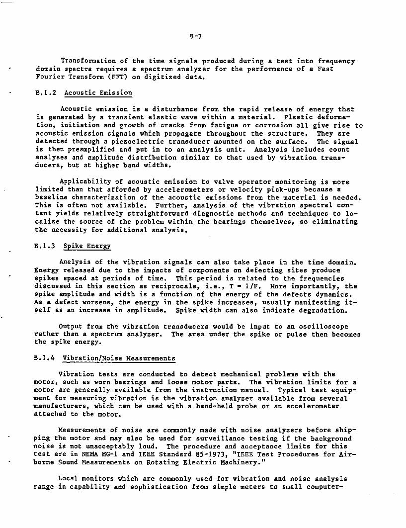
B-7
Transformation of the time signals produced during a test into frequencydomain spectra requires a spectrum analyzer for the performance of a FastFourier Transform (FFT) on digitized data.
B.1.2 Acoustic Emission
Acoustic emission is a disturbance from the rapid release of energy thatis generated by a transient elastic wave within a material. Plastic deforma-tion, initiation and growth of cracks from fatigue or corrosion all give rise toacoustic emission signals which propagate throughout the structure. They aredetected through a piezoelectric transducer mounted on the surface. The signalis then preamplified and put in to an analysis unit. Analysis includes countanalyses and amplitude distribution similar to that used by vibration trans-ducers, but at higher band widths.
Applicability of acoustic emission to valve operator monitoring is morelimited than that afforded by accelerometers or velocity pick-ups because abaseline characterization of the acoustic emissions from the material is needed.This is often not available. Further, analysis of the vibration spectral con-tent yields relatively straightforward diagnostic methods and techniques to lo-calize the source of the problem within the bearings themselves, so eliminatingthe necessity for additional analysis.
B.1.3 Spike Energy
Analysis of the vibration signals can also take place in the time domain.Energy released due to the impacts of components on defecting sites producespikes spaced at periods of time. This period is related to the frequenciesdiscussed in this section as reciprocals, i.e., T = 1/F. More importantly, thespike amplitude and width is a function of the energy of the defects dynamics.As a defect worsens, the energy in the spike increases, usually manifesting it-self as an increase in amplitude. Spike width can also indicate degradation.
Output from the vibration transducers would be input to an oscilloscoperather than a spectrum analyzer. The area under the spike or pulse then becomesthe spike energy.
B.1.4 Vibration/Noise Measurements
Vibration tests are conducted to detect mechanical problems with themotor, such as worn bearings and loose motor parts. The vibration limits for amotor are generally available from the instruction manual. Typical test equip-ment for measuring vibration is the vibration analyzer available from severalmanufacturers, which can be used with a hand-held probe or an accelerometerattached to the motor.
Measurements of noise are commonly made with noise analyzers before ship-ping the motor and may also be used for surveillance testing if the backgroundnoise is not unacceptably loud. The procedure and acceptance limits for thistest are in NEMA MG-1 and IEEE Standard 85-1973, "IEEE Test Procedures for Air-borne Sound Measurements on Rotating Electric Machinery."
Local monitors which are commonly used for vibration and noise analysisrange in capability and sophistication from simple meters to small computer-
B-8
driven data acquisition systems. Selection of the system is highly dependentupon the consequences of not detecting failure in advance, the cost of the moni-tor and the criticality of the equipment to the operation of the plant.
At the most fundamental and least expensive level of sophistication arealarm/alert monitors, which monitor the total root-mean-square (rms) content ofthe signal and/or peak-to-peak levels. Based on pre-selected limits, the moni-tor provides either an indicator for an alert condition or an indicator for analarm condition. Generally, there is no provision for actions by the monitor.Monitors can come in a number of channel configurations of two, four, six ormore. Limitations are based on the number of monitoring sites and their proxim-ity to the location of the monitor with its input channels.
Spectral analyzers provide the basis for comparisons in the frequency do-main. Expense increases with higher numbers of input channels, but costs arerelatively low for the two channel configurations. Limitations are the two chan-nels for monitoring signals.
The advent of the personal computer and its attendant signal analysis soft-ware packages provides a relatively low cost solution, allowing higher numbersof channels and performing similar levels of frequency analysis. There are manyvendors supplying hardware and software that can be added to the IBM PC, AppleIIEs, and HP personal computers, which can perform frequency analyses of 12 chan-nels and more at, fairly economic rates. Additionally, the PC-based monitoringsystem provides detailed analytical capability for comparisons of baseline withon-line data. Information can be stored for later, more detailed analysis orprocessed on the spot for "instant" diagnosis.
B.2 Temperature Measurements
Temperature readings as well as the rise in temperature of certain motorparts are many times indicative of the presence of high leakage or eddy currentflow, excessive friction and wear of rubbing surfaces, or blocking of coolingair or water flow passages. Temperature detectors are typically used in motorwindings, bearing housings or lubricating oil to detect any existing abnormali-ties. A large flow of current in the winding or failure of the cooling systemcould increase the winding temperature, leading to hot spots. Failure ofrollers or balls in the bearing assembly, insufficient or excessive lubrication,and high friction caused by rotor imbalance could lead to higher bearingtemperatures. In case of sleeve bearings, the lubricating oil temperature isvery critical to maintain proper viscosity and lubricity between the surfaces incontact.
Temperature measurements on larger motors are made periodically orcontinuously at the motor controllers or at the control room. Since the pumpand valve tech specs include component temperatures as a part of routine surveil-lance, they are considered to be a good practice for periodic measurement andhence included in the surveillance testing.
The discussion in this section is derived from the description provided inIEEE Standard 112-1978, "IEEE Standard Test Procedure for Polyphase InductionMotors and Generators." Four methods of measuring temperatures in motors andtheir applications are described and include:
B-9
* Embedded Detector (thermocouple or RTD)
Used for:
Standard Windings
Bearings (probe type or embedded detectors used)
* Winding Resistance
Used for:
Stator Windings (or rotor windings for a wound rotor motor)
* Local Temperature Detector
Used for:
Local temperatures of winding and core laminations which are not acces-sible to thermometers but can be measured by detectors (e.g.thermocouples, resistance temperature detectors or thermistors) thatare installed as permanent parts of the machine.
* Thermometer Method
Used for:
Stator Coils
Stator Core
Ambient
Discharge Air or Discharge Coolant.
The most commonly used temperature measuring devices for motors are thethermocouple (T/C), and resistance temperature detector (RTD). The thermistor(a temperature-sensitive semiconductor) is used as a protective device that canbe set to activate an alarm or relay at a predetermined temperature. It is dif-ficult to use when accuracy is important (because of the non-linearity of its re-sistance vs temperature curve), however, it is satisfactory as an alarm. Themost accurate readings are achieved with RTDs which can have an order of magni-tude better accuracy than the T/C.
The temperature of the copper winding can be determined by measuring theresistance of the winding at a known temperature, T (e.g. room temperature) andat the temperature of interest, T Substitution of these values and the valuesfor the resistances at TB (R B) anS at TT (RT) into the equation gives (from IEEEStandard 112-1978):
T ~ B RB BTT B ( + ) (TB -+ k)
B-10
where k = 234.5 for pure copper and K = 225 for aluminum, based on a volumeconductivity of 62 percent. For copper, which has an average temperaturecoefficient of resistance of approximately .004 ahm/ohm-0 C, the difference,RT - RB, for 200'C is approximately 0.8 ohms (B5). Since the resistanceof the winding is at least an order of magnitude greater than this, achievingan accurate value for TT is difficult because of the error resulting fromsmall differences from large numbers.
B.2.1 Bearing Temperature
Bearing temperatures are measured on large Motors as part of the plantsurveillance testing program. This measurement is particularly important forspecial bearings where the temperature is critical, such as oil lubricatedsleeve bearings, spherical roller bearings and plate bearings. Thermocouplesor resistance temperature detectors are installed on the motor so that theycontact the bearings and can easily detect the temperature changes. Theseinstruments are connected to alarm relays and often can shut the motor offshould the temperature exceed predetermined limits.
B.2.2 Winding Temperatures
Most large, high voltage form wound motors above 300 hp and voltages of4,000 volts and greater, have resistance temperature detectors or thermocou-ples embedded between the coils in the stator slots. These sensors measurethe winding hot spot temperatures that, together with the ambient, give thetotal winding temperature. Examples of total allowable temperatures are 130'Cfor motors with Class B insulation and 1550C for Class F insulation (given inNEMA MG-1). Winding temperature is a function of various factors includingmotor load (current), efficiency, ambient temperature, and motor cleanliness.
Sometimes the temperature sensors are mounted on the end turns of themotor or in the stator slots where they are used to monitor the winding tempe-rature during heat runs, in which the motor is run under a series of differentloads. Often, these sensors are used to transmit a signal to a device havingan alarm or circuit relay to protect the motor if the temperature exceeds apredetermined limit.
8.2.3 Oil Temperature
Large motors with sleeve bearings have oil reservoirs supplying continu-ous oil to the bearing. Depending on the condition of the bearing, the oilgets warmer by acquiring heat from the friction produced at the bearing's con-tact surfaces. In some cases, the temperature of the oil is measured by athermocouple or some other device to indicate the condition of the bearing.
B.3 Stroke Time (MOV)/Speed (Pump) Test
The stroke time test is necessary for valves that have performance crite-ria governed by the plant technical specifications. The test consists ofopening (closing) the valve until the indicator light shows it to be fully
B-il
opened (closed). The test can be conducted in the control room by using acalibrated stop-watch which is started when the valve is actuated, and stoppedwhen the light goes on to show that the end of the valve stroke has beenreached. The data from the check list obtained from stroke-time tests can bereviewed for trends in the stroke time. An increasing time may result frompoor maintenance or buildup of crud on seats that is causing overloading ofthe motor, or because of deterioration of the motor, itself. For example,improperly set limit/torque switches or stem packing that is excessivelytightened, can force the motor in the operator to work harder, leading tohigher than normal motor temperatures and more rapid aging of the insulation.
Rotating speed of shaft driven pumps, fans or other rotating componentscan be measured directly to monitor the condition of the motor, coupling, orthe driven equipment itself. For components directly coupled to motors ofeither synchronous or the induction type, the speed need not be measured perASME Section XI. However, it is a good practice to monitor the speed of suchequipment and compare it with the normal speed for operability.
B.4 Motor Operated Valve Testing
The NPAR study (B2,B3) on MOVs at Oak Ridge National Laboratory (ORNL) isdeveloping a testing device which will measure the following parameters:
motor currentvalve stem positionvalve stem velocity
* valve stem straintorque and limit switch actuations
* internal and external motor temperatureMOV acceleration
• torque switch shaft rotation
This testing provides the time dependent plots for each of the above para-meters. Evaluation of the current motor operational readiness can be obtainedby comparing the test data with the baseline (reference) plots.
The MOVATS* System is available from industry, which provides similarresults. The MOVATS test system simultaneously measures the stem load, themotor current, and control switch points. It assesses the electrical andmechanical MOV condition with a patented thrust measuring device and switchmonitoring circuit. The system can display on a CRT screen the signatures for
*MOVATS is a Motor Operated Valve Analysis Test System for diagnosing mechani-cal and electrical degradations. It is manufactured by MOVATS, Inc.,Marietta, GA .
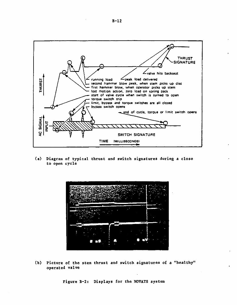
B-12
//t THRUST2 X / /g SIGNATURE
Zvalve hits backseat
I running load peak load deliveredc second hammer blow peak, when stem picks up disc
/\ first hammer blow, when operator picks up stemI /lost motion action, zero load on spring pack
start of valve cycle when switch is turned to opentorque switch trip
/// limit, bypass and torque switches are all closedbypass switch opens
-C \nd of cycle, torque or limit switch opens-j
0C,;Q SWITCH SIGNATURE
TIME (MILLISECONDSI
(a) Diagram of typical thrustto open cycle
and switch signatures during a close
(b) Picture of theoperated valve
stem thrust and switch signatures of a "healthy"
Figure B-2: Displays for the MOVATS system
B-13
(a) stem thrust, (b) control switch, and (c) motor current'and store them in acomputer or plot them. Two signatures can be displayed and stored simultan-eously, as shown in Figure B-2 (a). A picture of an actual trace on a CRTscreen is shown in Figure B-2 (b). The manufacturer claims that the followingparameters in an MOV can be determined:
• Load to unseat valve (hammerblow)* Running load* Load at torque switch trip* Available load (final load minus running load)• Valve cycle time* Time of hammerblow* Time at which close to open bypass switch opens* Operator inertia induced stem load* Final load* Starting motor current• Running motor current* Final motor current.
B.5 Reference
(Bi) Kerlin, T.W. and Shepard, R.L., "Industrial Temperature Measurement,"published by The Instrument Society of America (1982).
(B2) Greenstreet, W.L., et al., "Aging and Service Wear of Electric Motor-Operated Valves Used in Engineered Safety-Feature Systems of NuclearPower Plants," NUREG/CR-4234, June 1985.
(B3) Crowley, J.L. and Eissenberg, D.M., "Evaluation of the Motor-OperatedValve Analysis and Test System (MOVATS) to Detect Degradation, Incor-rect Adjustments, and Other Abnormalities in Motor-Operated Valves,"NUREG/CR-4380, January 1986.
C-1
APPENDIX C
CONTINUOUS MONITORING AND INSPECTION PROGRAMS
Page
C.1 Continuous Monitoring of Motors.................................C.2 Inspection of Motors..... ........................ ... . ....
C-2C-2
C-2
C. CONTINUOUS MONITORING AND INSPECTION PROGRAMS
The preceding two appendices have described various testing methods forevaluating the conditions of motor insulation and bearing assemblies. The twoother activities, continuous monitoring and inspection of motor conditions, pro-vide the other functional indicators to assess the condition of the motor perfor-mance. The following discussions include the procedures and the applicabilityfor these two maintenance activities to various motor applications and sizes.
C.1 Continuous Monitoring of Motors
Continuous monitoring of motors can be done without the aid of any sophis-ticated equipment or tools. In fact, most of the measuring devices arepermanently installed either at the installation or at the controller for themotor. These devices include ammeters, voltmeters, temperature indicators, andvibration sensors. Since they are not supplied with all motors, this particularactivity is applicable only to those motors having the instruments for suchreadouts.
Since most readings can be taken at the controllers which are generallylocated in a milder environment than are their motors, a more frequentmonitoring schedule is possible without too much inconvenience of personnel expo-sure. Some parameters for very large motors important to plant safety can beread by the control room operators. It is recommended that these parameters arelogged on an individual motor performance sheet while making the scheduled in-spection checks.
Parameters which are typically monitored continuously include line/phasecurrent or voltage, winding and bearing temperatures, lubricating oil tempera-tures and bearing vibration signals. Depending on the motor size, the windingand bearing temperatures are measured at several locations in thewinding/bearing housings. Vibration transducers usually are mounted on bearinghousings on intermediate to large size motors, since failure of bearing may leadto damages to the insulation which are expensive to repair.
Small motors used for driving safety components or valves are oftenequipped to indicate winding and bearing temperatures, line and phasecurrents/voltages; some have bearing vibration monitors. Intermediate and largesize motors also have instruments to provide readings for the above parameters.Some specially designed large motors, with heat exchangers for bearing cooling,have indicators to monitor oil temperatures, so providing valuable data forbearing condition, specifically for sleeve or plate bearings where oil plays animportant role in their life span.
Certain continuous monitoring parameters can be used in the on-linemonitoring system which logs data electronically and helps in trending them toassess motor condition. Some of these parameters, such as motor runningcurrents, are included in some plant technical specification as part of theirsurveillance testing.
C.2 Inspection of Motors
Motors, regardless of their sizes and types, should have a periodic inspec-tion to evaluate their condition. Such inspection requires listening to the
C-3
noise level, observing any surface degradation, applying hand forces to assessstructural integrity and electrical connections, etc. It is prudent to performsome of the regular maintenance activities (which include regressing, cleaning,replacing parts) at the same time. Motors critical to plant safety and avail-ability should have a more frequent schedule (such as quarterly to half yearly)than those are classified as less critical. However, it is recommended thatthese motors should be inspected at least once per operating cycle to ensuretheir overall reliability and operational readiness.
Individual motor maintenance manuals present the manufacturer'srecommended practices. The utility company modifies the recommendations, basedon usage and environment, by selecting the important activities for the particu-lar motor applications. Based on these recommendations, following is a "10-point" motor inspection program to protect the motor against various detrimentalelements. Precautionary measures for human health and safety prior to or afterthe inspection for a motor application are not included. Most of therecommended items can be done without any sophisticated testing or tools.
These recommendations are applicable to all size and type of motors. Cer-tain motors, especially large motors furnished with special features may requirean added checklist to address important subcomponents, such as coolers or protec-tive relays.
(1) Guard Against Dirt, Dust, and Contaminants
Although nuclear facilities are very clean when compared with someother industries, the insulating system and mechanical parts of the motor can ac-cumulate dust. A visual inspection of the condition should be made periodi-cally, especially for motors with open enclosures and exposed to a hostile envi-ronment. Dust, dirt and foreign particles that are free from oil orgrease may be removed by wiping clean with a dry cloth, or preferably, by suc-tion. Compressed air at a recommended pressure limit can be used to reach ob-jects in inaccessible areas. Low-pressure steam cleaning with a mild, neutral,and non-conducting detergent may be used to remove stubborn dirt from windingsand other parts of motors. It is important that the windings be thoroughlydried after the steam cleaning operation. When grease or oil is present, wipewith a cloth moistened with a recommended petroleum solvent of a 'safety-type.'
(2) Guard Against Moisture, Water, Grease or Lube Oil
Moisture intrusion into motor components significantly increases theprobability of motor failure. A wet insulating system can burn the windings,moisture in the air could short electrical connections, water in the bearing as-sembly could alter the lubricity of the lubricating agent, and moisture in chemi-cal reaction with air or oxygen could corrode mechanical parts made out ofmetals. Motors should always be guarded against the accidental intrusion ofwater from splatter or splashing, leakage from coolers, condensation from mois-ture inside the motor or intrusion of moisture from the environment. Spaceheaters or other heating devices should be used to thoroughly dry the motorbefore it returns to service.
Leakage of oil or grease from the bearing assembly onto motor parts willhelp the deposition of foreign particles on the motor or winding surfaces. Vi-
C-4
sual inspection of such leaks, combined with good preventive measure could elimi-nate many contact or insulation problems.
(3) Guard Against Friction
Visual inspection, higher temperatures, and an abnormal level ofsound during running may indicate excessive friction or overheating of bearingsand is usually traced to one of the following causes: (a) excessive belt ten-sion, (b) poor alignment causing excessive vibration or binding, (c) bent shaft,(d) excessive end or side thrust due to gearing, flexible coupling, and (e)damaged bearings.
(4) Guard Against Vibration
Excessive winding vibration could be caused from loose rotor bars orend rings, phase imbalance in the winding currents, jammed or frozen balls, lowlubrication level, and nonuniform clearances between stator and rotor windingsor a misaligned rotor shaft. Unusual bearing vibration level or noise level isan indication of low or excessive lube oil or grease, vibration transmitted fromthe driven component, degraded bearings, frozen or jammed balls or rollers, andexcessive load or thrust in bearings. Overall motor vibrations are caused bythe foundation settling or heavy floor loading, loose mounting bolts, base fix-tures or shims, excessive drive on the components, high electrical noise, etc.Since all of the above vibrations are observed or heard while the motor is run-ning, standby and intermittent motors should be inspected when they are in run-ning condition.
(5) Guard Against Adverse Environment
Humidity, temperature, radiation, and chemical spray affect the ageand performance of motor components. Therefore, motors required to run duringtimes after an accident for safety functions that are exposed to a harsher envi-ronment, should be shielded from these hostile conditions. A check should bemade to see if any of the above environmental parameters have exceeded theallowed limiting conditions. In addition, visual inspection for dislodged ob-jects hanging around the motor should eliminate any possibility of mechanicaldamage during a seismic or dynamic event.
(6) Guard Against Cracks/Corrosion
Surface corrosion or cracks on motor components can be detected bythorough visual inspection. The sources of corrosion include metallic compo-nents exposed to humid atmosphere where cracks may develop from an existing flawin the metal during manufacturing. High frequency vibrations in loads initiatecracks or voids at high stress regions. Corroded or cracked rotor bars and endrings could affect the motor dielectric life significantly. All the corroded re-gions should be scraped and cleaned, and then an anti-corrosion chemical orpaint used to keep these surfaces away from humid atmospheres. Many timescracked surfaces can be detected by just hearing the sound of the reflectedsoundwaves from these locations. If it is found that they have reached theircritical length so that complete failure is possible, then they should berepaired or replaced immediately. Otherwise, close monitoring of the crack prop-agation must be instituted in future inspections.
C-5
(7) Guard Against Electrical Stresses
Electrical stresses are caused by high voltages, high leakagecurrents, broken wires or shorts, etc. Without performing any electrical
* testing, a good inspection on insulation surfaces for corona discharges (whiteand grey deposits), burn marks, visible voids and cracks, and on bearing insula-tions can avoid much expensive maintenance. Shorts, burned and poor electricalconnection of wirings within the motor can be checked for possible disconnectionduring running.
(8) Guard Against Age and Service Wear
There are some components in a motor which have a finite life be-cause of their age and service wear. These components include seals, bearings,insulating systems, gaskets, carbon brushes and brush holders for dc or synchro-nous motors. Periodic checking on their conditions, as well as replacement atthe end of their specified life is an important aspect of the inspection pro-gram. Any service wear and mechanical component distortion due to cyclic ther-mal and mechanical aging should be checked periodically. Carbon deposits on con-tact points where sparking occurs while starting or running and on the commuta-tor surface for dc machines should be cleaned and wiped at frequent intervalswith a clean canvas cloth free from lint. If the commutator develops growingeccentricity, high bar or mica, the armature should be removed and the surfaceshould be ground, polished and beveled as instructed by the manufacturers.Regreasing bearings at regular intervals is also a part of a good maintenancepractice. A typical life for bearings in small motors is 10-12 years.
(9) Guard Against Human Errors
Dedicated crews inspecting motors as well as performing maintenancesuch as regressing bearings, cleaning contacts, replacing carbon brushes,gaskets, and seals, air blasting, can eliminate most of the problems created byhumans. Good planning and scheduling will cover the motors at regularintervals, in accordance with their importance to plant safety and availability.A comprehensive inspection checklist should be developed for each size and typeof motor to guard against its omission. An independent inspection by a quali-fied individual should insure that the activities were performed correctly andthe motor is left in an operationally ready state.
(10) Guard Against Loss of Inspection Data
Although a motor inspection does not provide any data which can beused to predicting future performance, logging all the inspection activitiesdescribing the condition of motor on a log sheet, such as spare part/grease typeidentifications and other relevant information will help monitor the motor andmay provide insight into environmental conditions which could impact its perfor-mance. A computerized system can effectively enhance the data management andthe data stored can be used for root cause analysis when a motor fails.
D-1
APPENDIX D
MOTORS IN NUCLEAR POWER PLANTS
Page
D.1 Motor Auxilliaries Design and Specifications.....................D.1.1 Enclosures ................................................D.1.2 Grounding ...................................... ...........D.1.3 Bearing Protection................ . ..... ................D.1.4 Thermal Protection..............................D.1.5 Phase Overcurrent Protection..............................D.1.6 Differential Protection.......... ......... .. .............D.1.7 Surge Protection,................... .......... ...........D.1.8 Additional Motor Protection Considerations................
D.2 Motor Population and Applications................................D.2.1 Critical Motors for Plant Safety and Plant
Availability .............. ........... .............D.2.2 Motors in Boiling Water Reactor (PWR) Plants............D.2.3 Motors in Pressurized Water Reactor (PWR) Plants .........
D-2D-2D-3D-3D-3D-4D-4D-4D-4D-5
D-6D-7D-10
D-2
D. MOTORS IN NUCLEAR POWER PLANTS
This appendix discusses the various elements one would consider inspecifying a motor for an application. Since plants are designed by many differ-ent architectural engineering (AX) and nuclear steam supply system (NSSS) firms,motor specifications for a particular application vary, but not significantly so.
The typical nuclear power motor populatin is presented according to sizeand type of environment.
D. Motor Auxilliaries Design and Specifications
The design and specification requirements for selectin a motor for anyparticular application were discussed in the phase I report M7). This sectiondiscusses other auxilliary equipment needed for motor operation, includingswitching devices or control equipment, and protection devices.
When specifying motor switching or control equipment the following must beconsidered:
* starting frequency or application (continuous duty or intermittent,such as valve operators)
* multispeed and reversing operation capability* motor size (hp)* motor supply voltage* motor short-circuit current.
For complete motor protection, these data must be available:
* full load current* service factor* locked rotor current at minimum and rated starting voltages* starting method employed* acceleration time (starting time) at minimum voltage and rated starting
voltage* operating duty cycle such as frequency of starts, duration and degree
of overloading* safe stall time at minimum voltage, starting voltage, ambient tempera-
ture and operating temperature* power supply data such as voltage variation, unbalance, etc.
The following subsections contain discussions of other details which must beconsidered when specifying motor auxilliaries.
D.l.l Enclosures
Motors for indoor service generally are put in open dripproof enclosures,while for outdoor service they are totally enclosed in fan-cooled (TEFC)weather protected enclosures. Both of these enclosures have drains. Nuclearpower plants located near salt water or in environments with hostile atmosphericconditions should consider the TEFC enclosure for indoor applications. When totally enclosed water to air cooled motors (TEWAC) are used, the design ofcoolers should be such that water from leaks in the tube do not affect the di-electric integrity of motors.
D-3
* D.1.2 Grounding
Each motor has means for grounding the frame. For integral motors, many* times there exist two grounding means located in diametrically opposite corners
of the motor. These are non-corrosion pads, welded or brazed to the motorframe: one is generally sited on the main lead conduit box side of the motor.
D.1.3 Bearing Protection
Motors up to about 250 hp usually are furnished with antifriction ball orroller bearings. Horizontal motors above 250 hp are equipped with sleevebearings. Large vertical motors have antifriction (ball, roller or sphericalroller) and plate type thrust bearings up to 4000 hp. Motors with antifrictionbearings are equipped with oil or grease fittings, so that a lubricant can beforced through the bearing housing without disassembling the motor. Sleevebearings are often of the ring-oiled type except where pressurized oiling is pro-vided. In this case, bearings have split-type housing and split-end shieldsarranged in such a way that the bearing may be inspected and replaced withouttoo much difficulty. Some antifriction bearings, especially those for valveoperators, are sealed units requiring no regular maintenance and are replaced atthe end of their life, as recommended by the manufacturer. Bearing lubricantsshould be the ones recommended by the manufacturers.
Protective devices for bearings are responsive to one or more of the fol-lowing conditions, which can lead to bearing failure:
• lack of or too much lubricant* low oil level in reservoir* low oil pressure* reduced oil flow* high bearing or oil temperature* rate of temperature rise* vibrations.
Some special large size motors are equipped with Resistance Temperature De-tectors (RTDs) in place of thermocouples to monitor bearing or oil temperature,because RTDs offer faster response and are more accurate. Vibration transducersare also mounted on the bearing housing to monitor abnormalities.
D.1.4 Thermal Protection
Thermal detectors are utilized to detect the motor winding temperature dur-ing normal and abnormal conditions. Abnormal conditions which can causeoverheating include:
* overload* restricted motor ventilation* reduced speed operation* frequent starting
* * low line voltage* high line voltage, with or without low line frequency (over-excitation)* mechanical failure of the motor bearing, of the driven equipment or
of the coupling between the motor shaft and the driven equipment
D-4
* improper installation* unbalanced line voltages, including single phasing.
Thermal detectors which can be embedded in the stator windings includethermocouples, RTDs, thermal protectors such as GE Thermo-Tectors andthermisters (nonlinear RTDs). Thermocouples often are installed in random woundstator coils, whereas RTDs are used in form-wound coils. Generally, 6 RTDs areinstalled in large motors above 1500 hp (two per phase) and 3 RTDs are put intomotors less than 1250 hp (one per phase). RTDs may be connected to initiatean alarm or to shut off the motor.
D.1.5 Phase Overcurrent Protection
Small motors are equipped with overcurrent relays with one instantaneousunit and one long-time delay unit to protect against severe overloads, lockedrotor, and line faults. On large motors, the use of overcurrent relays with two in-stantaneous units is preferred, one with normal dropout and the other with highdropout and a timer. This arrangement limits iron damage and bus voltage dis-turbances due to faults resulting in a current just above the locked rotor cur-rent.
D.1.6 Differential Protection
When the locked rotor current exceeds 5 percent of the symmetrical 3-phasefault current available at the switchgear, differential relay protection is usedwith the instantaneous overcurrent relays. These devices respond to fault currentswhich are limited by the fault impedence to a current level lower than the loadcurrent. It is reasonable to assume that most multiphase faults begin as a low-level current and gradually build up to a high level. Thus, the differential relaycan prevent a great deal of burning damage.
D.1.7 Surge Protection
Figure D-1 illustrates the surge limits which a motor can withstand andstill provide satisfactory service. Damaging surges may be caused by switching,including switching the motor itself, and other breaker contact problems. It isgenerally recommended to provide protection with surge capacitors for certainmotors. These devices must be mounted in the motor conduit box to be effective.
D.1.8 Additional Motor Protection Considerations
Other design considerations to protect motors from degradation or failureare:
* flexible couplings between motor and the driven equipment* mounting and doweling* drainage for water accumulation inside the motor* insulation material damage other than heating* operating environment of motor* noise level of motor* leads and terminals* instrumentation and control
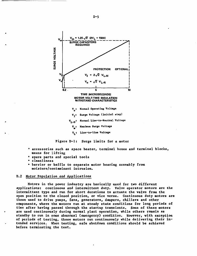
D-5
a, i
I/I
= ~PROTECTION OPTIONALI
Vy - 2 2 VLNl
Vo Vo - /12 VL-N|
0.2. 5 10
TIME (MICROSECONDS)MOTOR VOLT-TIME INSULATIONWITHSTAND CHARACTERISTICS
V : Normal Operating Voltage0
VI: Surge Voltage (initial step)
VLN: Normal Line-to-Neutral Voltage
V Maximum Surge Voltage
VL: Line-to-line Voltage
Figure D-1: Surge limits for a motor
* accessories such as space heater, terminal boxes and terminal blocks,means for lifting
* spare parts and special tools* cleanliness* barrier or baffle to separate motor bearing assembly frommoisture/contaminant intrusion.
D.2 Motor Population and Applications
Motors in the power industry are basically used for two differentapplications: continuous and intermittent duty. Valve operator motors are theintermittent type and run for short durations to actuate the valve from theopen position to the closed position, or vice versa. Continuous duty motors arethose used to drive pumps, fans, generators, dampers, chillers and othercomponents, where the motors run at steady state conditions for long periods oftime after having passed through the startup transients. Some of these motors
* are used continuously during normal plant operation, while others remain asstandby to run in some abnormal (emergency) condition. However, with exceptionof periods of testing, these motors run continuously while delivering their in-tended services. When testing, safe shutdown conditions should be achieved
before terminating the test.
D-6
This section discusses different nuclear power plant (NPP) systems thatcontain electric motors. The terms safety-related and nonsafety-related areused to indicate those systems and motors most important to ensuring plant andpublic safety. At a NPP the term safety-related is well defined and desig-nates those systems and components agreed upon by the NRC and the utility asncessary to prevent or mitigate the consequences of Final Safety-AnalysisReport (FSAR) assumed accidents. These components and systems are usuallycontained on a Quality or Q list at the plant. Other components and systemswhich also contribute to safe plant operation but to a lesser extent are some-times referred to as important to safety. There is much discussion in theindustry about these components. This report will stay primarily with thesafety-related groupings. However, some of the recommendations made forsafety-related motors could be applied to a larger class of motors.
B.2.1 Critical Motors for Plant Safety and Plant Availability
It is imperative that safety motors remain capable of functioningthroughout their life. Large non-safety motors which have a high cost impact,both for replacement and their importance to plant availability must also behighly reliable. Hence, these motors require more rigorous maintenance andsurveillance to maintain them in good operating condition.
Since each plant system design is different, it is difficult to identifyall systems in the above category. The following is a list of some of theimportant systems:
Emergency Core Cooling Systems (ECCS) which include. Residual Heat Removal (RHR)/Low Pressure Coolant Injection (LPCI). Core Spray (CS)• High Pressure Coolant Injection (HPCI). High Pressure Core Spray (HPCS). Reactor Core Isolation Coolant (RCIC). Safety Injection (SI). Charging System. Decay Heat RemovalContainment Heat Removal (CHR)Chemical and Volume Control System (CVCS)Emergency Power System.
From a plant risk standpoint, studies (e.g. probabilistic risk assess-ment) have shown that failure of certain support systems such as service wateror component cooling water, can significantly impact frontline systems. Inthe past, these key support systems may not have received adequate attention,but increased attention is crucial to ensure plant safety. For example, comrponent cooling water and service water systems are required for proper func-tioning of safety components and systems such as reactor coolant pump seals,diesels, control room HVAC, containment coolers, emergency diesel generators,RHR heat exchangers and RHR pumps. Some other support systems are:
. Gas Radiation Waste Management
. Heating, Ventilation and Air Conditioning (IVAC)
. Containment Isolation System
D-7
* Containment Gas Control* Fire Protection* Radiation Monitoring* Condensate and Feedwater.
As previously mentioned, some large non-safety motors require good mainte-nance because of their replacement cost. The reactor coolant pump motors inthe case of a PWR system and the recirculation pump motors for BWR systems arenon-safety related, but very important for plant availability. Other motorswhich can be considered in this category are:
* circulating water* condensate* condensate booster* main feed water* turbine building cooling water* control rod drive* reactor water cleanup.
D.2.2 Motors in Boiling Water Reactor (BWR) Plants
The motor population in a BWR station is directly proportional to the num-ber of systems existing. The earliest BWR plants had a drywell and torus con-tainment arrangement, designated as a Mark I. The Mark I had fewer systems,both safety and non-safety related, when compared with the later BWR designs,primarily the Mark II, or the most recent Mark III. Both the Mark II and MarkIII design contain about the same number and type of fluid systems and hence,the motor population does not differ significantly. Table D-1 illustrates themotor population breakdown compiled from selected plants of each design type*.
BWR designs have two recirculation loops connected to the reactor vesselwith two recirculation pumps located inside the contaminant in a high radiationzone. These two motors are large three-phase vertical induction motors of ap-proximately 5,000 hp. Although these motors are classified as non-safety, theyare important because of their impact on plant availability. Corrective mainte-nance is expensive due to the location of the motor and its size.
Environmental conditions at various plant locations are also important fac-tors for considering motor age-related degradation rates. Table D-2 providesthese parameters for inside and outside the primary containment. High radiationzones are: inside the primary contaminant where the recirculation motors arelocated, main steam/feed water tunnel, reactor water clean-up pump area. Otherareas inside the secondary containment and outside the primary containment withlower radiation levels are: control rod drive hydraulic unit areas, RHRand core spray pump area, HPCI and RCIC pump area, fuel pool clean-up pumps, andcontainment fan cooler. Motors outside the containment area in the turbinebuilding can experience high radiation. These areas include the reactor feedpump area, condenser area, and main turbine area. Other buildings, except forradwaste, have no significant radiation, but could experience high humidity andtemperature conditions.
*Compiled by Ebasco Services, Inc. under contract to BNL.
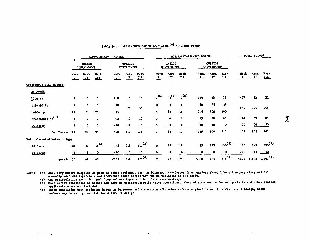
Table D-It APPROXIMATE MOtOR POPULATION (a) IN A BvR PLANT
SAFETY-RELATED MOTORS NONSAFETY-RELATED MOTORS TOTAL MOTORS
INSIDECONTAINMENT
Mark Mark MarkI II III
OUTSIDECONTAINMENT
Mark Hark MarkI II III
INSIDECONTAINMENT
Mark Mark MarkI II III
OUTSIDECONTAINMENT
Mark Mark Hark Mark Mark MarkI II III I II III
Continuous Duty Motors
AC POWER
.300 bp
125-250 hp
1-100 hp I
Fractional hp(c)
DC Power
Sub-Total: I
Motor Operated Valve Motors
O 0 0
O 0 5
.0 20 25
O 0 0
O 0 0
.0 20 30
<10
10
15
<5
<10
<50
45
<10
(105
15 15 2 (b)
070 90
5
15 20 0
10 10 0
110 135 7
2 (b)
0
10
0
0
12
2(b)
0
10
0
0
12
<15
10
205
15
10
255
15
35
390
50
10
500
235
0
735
15
35
400
65
10
525
190o d)
0
715(d)
<27 32 32
255 525 565
<20 65 85
<20 20 20
322 642 702
AC Power
DC Power
20 20
0 0
Total: 30 40
15(d)
0
45
215 180(d)
15 10
340 325(d)
0 15 10
0 0 0
7 27 22
75
0
<330
140
(10
<472
485
15
1,142
395(d)
10
1,*07 (d)
Notes: (a) Auxiliary motors supplied as part of other equipment such as blowers, transformer fans, cabinet fans, lube oil motor, etc., are notnormally recorded separately and therefore their totals may not be reflected in the table.
(b) One recirculation motor for each loop and are important for plant availability.(c) Most safety fractional hp motors are part of electrohydraulic valve operations. Control room motors for strip charts and other control
applications are not included.(d) These quantities were estimated based on judgement and comparison with other reference plant data. In a real plant design, these
numbers may be as high as that for a Hark II design.
',
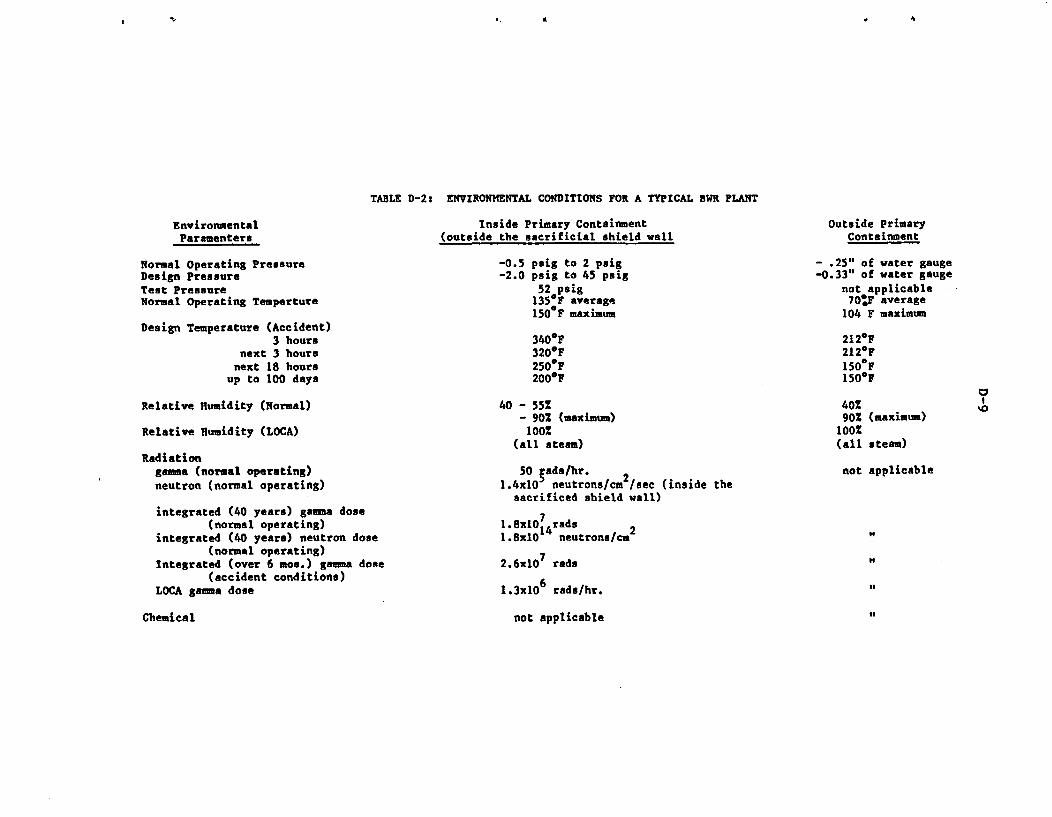
A.
TABLE D-2: ENVIRONMENTAL CONDITIONS FOR A TYPICAL 3WR PLANT
Environmental Inside Primary ContainmentParamenters (outside the sacrificial shield wall
Normal Operating Pressure -0.5 psi5 to 2 psigDesign Pressure -2.0 psig to 45 psigTest Pressure 52 psigNormal Operating Temperture 135OF average
150 F maximumDesign Temperature (Accident)
3 hours 340°Fnext 3 hours 320°F
next 18 hours 250 Fup to 100 days 200°F
Relative Humidity (Normal) 40 - 55%- 902 (maximum)
Relative Humidity (LOCA) 100%(all steam)
Radiationgama (normal operating) 50 5ads/hr. 2neutron (normal operating) 1.4x1O neutrons/cm /sec (inside the
sacrificed shield wall)integrated (40 years) gamma dose 7
(normal operating) 1.8xlO14 rads 2integrated (40 years) neutron dose 1.8x10 neutrons/cm
(normal operating) 7Integrated (over 6 mos.) gamma dose 2.6x1O rads
(accident conditions) 6
LOCA gama dose 1.3x10 rads/hr.
Chemical not applicable
Outside PrimaryContainment
- .25" of water gauge-0.33" of water gauge
not applicable70:F average
104 F maximum
212eF212eF150'F150"F
40%90X (maximum)
100%(all steam)
not applicable
to
of
of
of
is
D-10
Among safety systems, many large motors are 4 Kv, 3 phase vertical induc-tion motors with plate or ball bearings. They must operate during accident con-ditions to accomplish their safety function, and therefore must be capable ofoperating in both mild and harsh environments. The motors responsible for suchfunctions are typically reactor heat removal, core spray, and fan cooler motors.
Intermediate size safety motors include the service water pumps, reactorbuilding cooling water pump and control rod drive water pump'. These motors arelocated indoors, have antifriction bearings, 3 *, induction motors and areexposed to both harsh and mild environments. Continuous duty small integraland fractional motors are used all over the plant, both inside the reactor build-ing and in other auxiliary structures. They are generally fed from the 460 vbus lines and have antifriction bearings. The typical safety systems includecontainment HVAC, standby liquid or gas control, emergency diesel generator,chilled water, and support systems for safe shutdown of the reactor. Some smalldc motors are used as back ups for small ac pump motors in the event of a sta-tion blackout or loss of offsite power.
Intermittent motors, a class of motors which are typically fractional orsmall integral, are used in valve operators. These motors are designed to havehigh starting torque, and have weather proof, explosion proof or submersibleenclosures, with grease-sealed ball bearings. They can be either ac or dc, withthe ac motors being of the squirrel cage design and the dc motors being compoundwound. The ac power supply is from 110 v to 460 v bus lines and the dc voltageis 125 v or 250 v. Most important inside containment valves belong to the RHR,nuclear steam supply shutoff (containment isolation) and reactor recirculationsystems. Outside primary containment motors include RHR, Core Spray, HPCI,RCIC, CRD, and Component Water (CCW) and are classified to be exposed to mild en-vironment with the exception of those valves located in areas where high energypiping is routed. These valves are generally designed for the environmentresulting from a high energy line break (HELB).
D.2.3 Motors in Pressurized Water Reactor (PWR) Plants
Unlike BWR plants where General Electric is the sole supplier of the nu-clear steam supply (NSSS) system, three companies (Westinghouse, CombustionEngineering and Babcock & Wilcox) are principal NSSS suppliers. The balance-of-plant (BOP) design is done by any one of several architectural engineeringfirms. Since the motor population is a strong function of the plant design,there exists quite a variation in the number and size of motors at PWRfacilities. However, the variation is not wide enough to warrant consideringeach plant design separately. This section identifies safety and non-safety re-lated motors based on a PWR plant design. An approximate motor population in atypical PWR plant is given in Table D-3.
A PWR facility consists of a reactor building, turbine building, andassociated auxiliary buildings. The PWR primary systems and steam generatorsare completely enclosed inside the reactor building. Because of this arrange-ment, a larger number of motors are located inside the reactor building (or pri-mary containment) than in the primary containment of a BWR. Table D-4 providesthe normal and accident environmental parameters for inside and outside the con-tainment shell. Some of the auxiliary buildings of the PWR which house equip-ment driven by electric motors may not be exposed to significant radiation, but
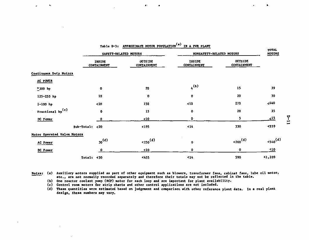
C. t16
Table D-3: APPROXIMATE MOTOR POPULATION(a) IN A PWR PLANTTOTALMOTORSSAFETY-RELATED MOTORS NONSAFETY-RELATED MOTORS
INSIDECONTAINMENT
OUTSIDECONTAINMENT
INSIDECONTAINMENT
OUTSIDECONTAINMENT
Continuous Duty Motors
AC POWER
>300 hp
125-250 hp
1-100 hp
Fractional hp(c)
DC Power
0
10
<10
20
0
150
4(b) 15 39
0 20 30
<10
0
270 <440
0 15 20 35
<15n ei1 0 5 0I
Sub-Total: <20 <195 <14 330 <559
Motor Operated Valve Motors
AC Power 30 (d)
0
<250(d)
<10
<540(d)0
DC Power 0 0 <10
Total: <50 <455 <14 590 <1,109
Notes: (a) Auxiliary motors supplied as part of other equipment such as blowers, transformer fans, cabinet fans, lube oil motor,etc., are not normally recorded separately and therefore their totals may not be reflected in the table.
(b) One reactor coolant pump (RCP) motor for each loop and are important for plant availability.(c) Control room motors for strip charts and other control applications are not included.(d) These quantities were estimated based on judgement and comparison with other reference plant data. In a real plant
design, these numbers may vary.
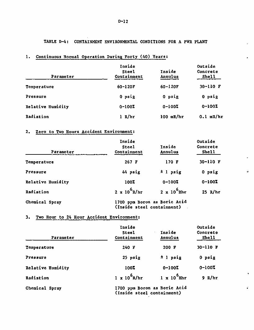
D-1 2
TABLE D-4: CONTAINMENT ENVIRONMENTAL CONDITIONS FOR A PWR PLANT
1. Continuous Normal Operation During Forty (40) Years:
InsideSteel Ins
Parameter Containment Ann
Temperature 60-120F 60-
Pressure 0 psig 0
Relative Humidity 0-100% 0-
Radiation 1 R/hr 100
ideulus
120F
psig
100%
mR/hr
OutsideConcrete
Shell
30-110 F
0 psig
0-100%
0.1 mR/hr
2. Zero to Two Hours Accident Environment:
InsideSteel Inside
Parameter Containment Annulus
Temperature 267 F 170 F
Pressure 44 psig 1 psig
Relative Humidity 100% 0-100%
Radiation 2 x 10⁶R/hr 2 x 10 Rhr
Chemical Spray 1700 ppm Boron as Boric Acid(Inside steel containment)
3. Two Hour to 24 Hour Accident Environment:
OutsideConcreteShell
30-110 F
o psig
0-100%
25 R/hr
Parameter
Temperature
Pressure
Relative Humidity
Radiation
Chemical Spray
InsideSteel Inside
Containment Annulus
240 F 200 F
25 psi g ± I psig
100% 0-100%
1 x 10 R/hr 1 x 10 6Rhr
1700 ppm Boron as Boric Acid(Inside steel containment)
OutsideConcrete
Shell
30-110 F
o psig
0-100%
9 R/hr
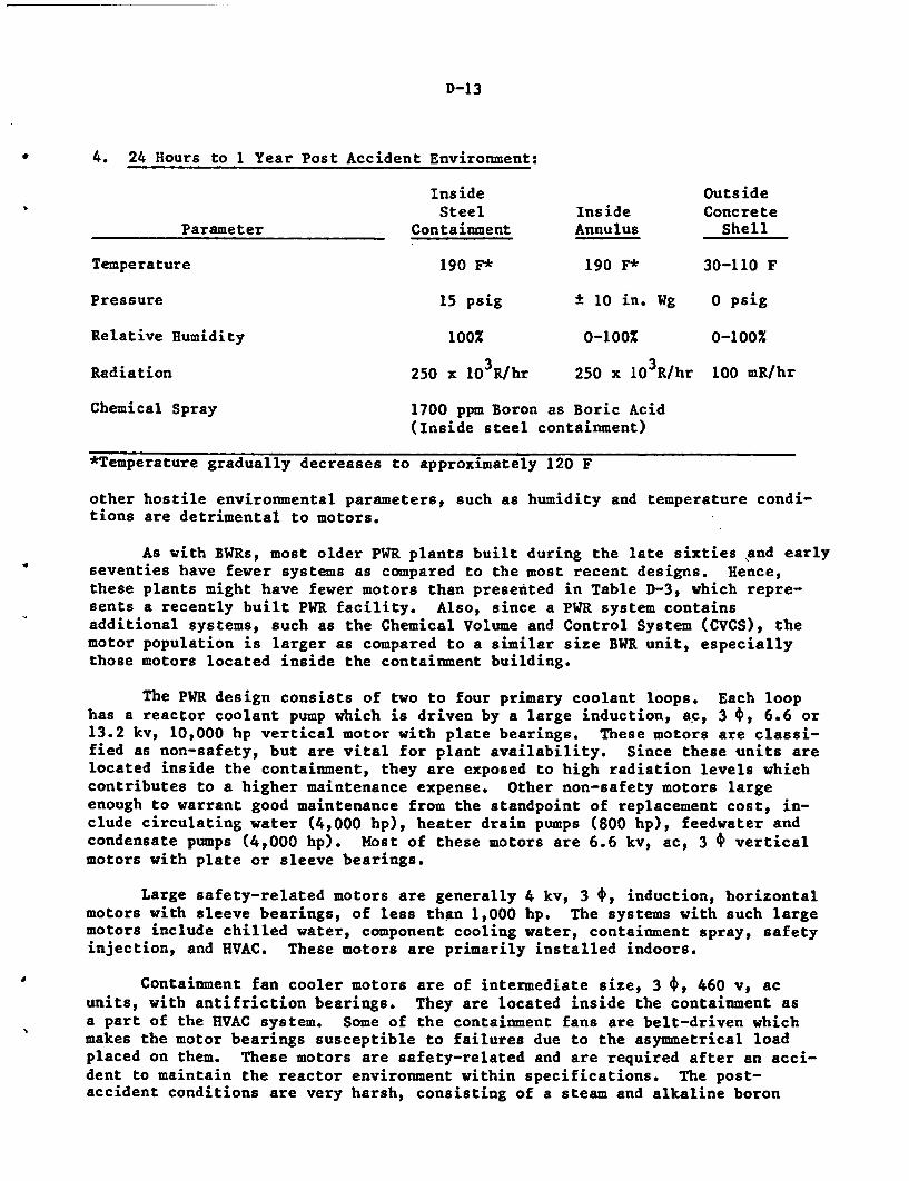
D-13
4. 24 Hours to 1 Year Post Accident Environment:
Inside OutsideSteel Inside Concrete
Parameter Containment Annulus Shell
Temperature 190 F* 190 F* 30-110 F
Pressure 15 psig ± lOin. Wg 0 psig
Relative Humidity 100% 0-100% 0-100%
Radiation 250 x 103R/hr 250 x lO3R/hr 100 mR/hr
Chemical Spray 1700 ppm Boron as Boric Acid(Inside steel containment)
*Temperature gradually decreases to approximately 120 F
other hostile environmental parameters, such as humidity and temperature condi-tions are detrimental to motors.
As with BWRs, most older PWR plants built during the late sixties and earlyseventies have fewer systems as compared to the most recent designs. Hence,these plants might have fewer motors than presented in Table D-3, which repre-sents a recently built PWR facility. Also, since a PWR system containsadditional systems, such as the Chemical Volume and Control System (CVCS), themotor population is larger as compared to a similar size BWR unit, especiallythose motors located inside the containment building.
The PWR design consists of two to four primary coolant loops. Each loophas a reactor coolant pump which is driven by a large induction, ac, 3 *, 6.6 or13.2 kv, 10,000 hp vertical motor with plate bearings. These motors are classi-fied as non-safety, but are vital for plant availability. Since these units arelocated inside the containment, they are exposed to high radiation levels whichcontributes to a higher maintenance expense. Other non-safety motors largeenough to warrant good maintenance from the standpoint of replacement cost, in-clude circulating water (4,000 hp), heater drain pumps (800 hp), feedwater andcondensate pumps (4,000 hp). Most of these motors are 6.6 kv, ac, 3 * verticalmotors with plate or sleeve bearings.
Large safety-related motors are generally 4 kv, 3 t, induction, horizontalmotors with sleeve bearings, of less than 1,000 hp. The systems with such largemotors include chilled water, component cooling water, containment spray, safetyinjection, and HVAC. These motors are primarily installed indoors.
Containment fan cooler motors are of intermediate size, 3 t, 460 v, acunits, with antifriction bearings. They are located inside the containment asa part of the HVAC system. Some of the containment fans are belt-driven whichmakes the motor bearings susceptible to failures due to the asymmetrical loadplaced on them. These motors are safety-related and are required after an acci-dent to maintain the reactor environment within specifications. The post-accident conditions are very harsh, consisting of a steam and alkaline boron
D-14
spray environment (4). According to 10 CFR 50.49, containment coolers must bequalified for their environment/service condition.
Safety-related small and fractional motors exist all over the plant in al-most every safety system. Except for a few dc motors that are used for backupequipment in case of complete ac power loss or station blackout, most motors inthis classification are ac, 3 *, induction motors with antifriction bearings andare fed from a 110 v to 480 v power supply. These motors primarily drive smallpumps for coolers, dampers and other smaller components. With the exception ofthose located inside the containment building, motors are exposed to a mild envi-ronment under normal operating conditions.
The valve motors which exist in PWR safety systems are small inductiontype, pipe mounted motors, similar to those in a BWR plant. Since a comparablesize PWR unit contains some additional safety systems, such as the CVCS which isalso a very large system, the valve motor population is larger than that of aBWR plant. The PWR safety injection system has some safety valves inside thecontainment stemming from the primary loops. These valve motors are exposed toharsh environment and are vital to plant safety.
0
INTERNAL DISTRIBUTION
1 R. Bari 12 H. Kouts2 J. Boccio 13 R. Lofaro3 A. Fresco 14 W. Luckas4 R. Fullwood 15-16 Nuclear Safety Library
5-7 W. Gunther 17 W. Shier8 R. Hall 18-21 M. Subudhi9 J. Higgins 22 K. Sullivan
10 R. Hodor 23-24 J. Taylor11 W. Kato 25 M. Villaran
EXTERNAL DISTRIBUTION
26-30 S.K. Aggarwal, U.S. Nuclear Regulatory Commission, 5650 Nicholson Lane,Rockville, MD 20852
31 S.P. Carfagno, Franklin Research Center, 20th & Race Streets,Philadelphia, Pk 19103
32 D.M. Eissenberg, Oak Ridge National Laboratory, Bldg. 9201-3,P.O. Box Y, Oak Ridge, TN 37830
33 W.S. Farmer, Division of Engineering Technology, Office of NuclearRegulatory Research, U.S. Nuclear Regulatory Commission, 5650 NicholsonLane, Rockville, MD 20852
34 L. Gradin, EcoTech, Inc. 6702 Bergenline Avenue, West New York, NJ07093
35 A.B. Johnson, Pacific Northwest Laboratory, P.O. Box 999, Richland, WA99352
36 P. McDonald, EG&G Idaho, Inc., P.O. Box 1625, WCB-3, Idaho Falls, ID83415
37 C. Michelson, ACRS, 20 Argonne Plaza, Suite 365, Oak Ridge, TN 3783038 Ben Nead, Biddle Instruments, 510 Township Line Road, Blue Bell, PA
1942239 Steven Peschel, Hipotronics, Inc., Brewster, NY 1050940 David Schump, Baker Instruments, P.O. Box 587, Ft. Collins, Co 80522
41-43 Marvin Sheets, NUTECH, 145 Martinvale Lane, San Jose, CA 9511944 K.M. Skreiner, NUTECH, 145 Hartinvale Lane, San Jose, CA 9511945 Wendell Starr, 25700 Deerfield Dr., Los Altos Hills, CA 94022
46-48 A. C. Sugarman, ENRAC, 450 San Antonio Road, Suite 11, Palo Alto, CA94306
49 D.F. Sullivan, Division of Engineering Technology, Office of NuclearRegulatory Research, U.S. Nuclear Regulatory Commission, 5650 NicholsonLane, Rockville, MD 20852
50 J.P. Vora, Division of Engineering Technology, Office of NuclearRegulatory Research, U.S. Nuclear Regulatory Commission, 5650 NicholsonLane, Rockville, MD 20852
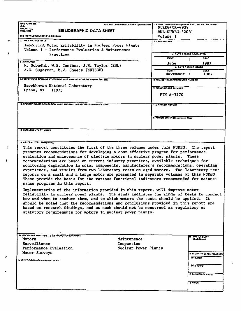
mRC FtORM 335 U.S. UCLEAR REGULATORY COMISSION 1 REPORTNUMSERJAAGsgn.v 55C. &Wd 9O@ NO.3 4.WI
NAM12102 NUREG/CR-4939,. a20 BIBLIOGRAPHIC DATA SHEET BNL-NUREG-52031SEE INSTRUCTIONS ON THE REVERSE Volume I2 TITLE AND SUBTITLE 3 LEAVE BLANK
Improving Motor Reliability in Nuclear Power PlantsVolume 1 - Performance Evaluation & Maintenance
Practices .DATE REPORT COMPLETED
S. AUTORISIT YEAR
M. Subudhi, W.E. Gunther, J.H. Taylor (BNL) June 1987G. DATE REPORT ISSUED
A.C. Sugarman, M.W. Sheets (NUTECH) MONTH I YEAR
November 1 1987
7. PERFORMING ORGANIZATION NAME AND MAILING ADDRESS ifudZ Coe S. PROJECTITASKIWORK UNIT NUMBER
Brookhaven National Laboratory 9. PIN OR GRANT NUMBER
Upton, NY 11973FIN A-3270
10. SPONSORING ORGANIZATION NAME AND MAILING ADDRESS mdrAgIZoCo I Is. TYPE OF REPORT
b. PERIOD COVERED (Inch" dim"
12. SUPPLEMENTARY NOTES
lA _wV z NAW | MW _1 w We
This report constitutes the first of the three volumes under this NUREG. The report
presents recommendations for developing a cost-effective program for performance
evaluation and maintenance of electric motors in nuclear power plants. These
recommendations are based on current industry practices, available techniques for
monitoring degradation in motor components, manufacturer's recommendations, operating
experience, and results from two laboratory tests on aged motors. Two laboratory testreports on a small and a large motor are presented in separate volumes of this NUREG.These provide the basis for the various functional indicators recommended for mainte-
nance programs in this report.
Implementation of the information provided in this report, will improve motorreliability in nuclear power plants. The study indicates the kinds of tests to conduct
how and when to conduct them, and to which motors the tests should be applied. It
should be noted that the recommendations and conclusions provided in this report are
based on research findings, and as such should not be construed as regulatory or
statutory requirements for motors in nuclear power plants.
I DOCUMENT hNALYSIS -a. KgEYWOROSIOESCRIPTORS IS AVAILABILITY
Motors Maintenance STATEMENT
Surveillance InspectionPerformance Evaluation Nuclear Power Plants
Motor Surveys 16 SECURITYCLASSIPICATION
I IOENTIFIERSIOPEN.gNoED TERMS
(Too, No".
17 NUMBER Of PAGES
IS PRICE
* U.S. GOVERNMENT PRINTING OFFICE: 1987-511-036/60003