Embed Size (px)
Citation preview
www.theinternationaljournal.org > RJSITM: Volume: 02, Number: 04, February-2013 Page 18
Improving Quality of Vehicle Tracking Systems in Hill Stations Using IEEE
802.16 Networks
Roop Singh Takur(M.Tech CSE), Assistant Professor, Cyryx College(Help University) &
E.Ramkumar(M.C.A)
Assistant Professor, Cyryx College (Help University)
ABSTRACT:
IEEE 802.16 standard was designed to support the vehicle tracking system applications with quality of
service(QOS). Tracking system is used for tracking the vehicles in hill stations with quality of
service(QOS). With the help of subscriber station(SS) can track the vehicles. Subscriber station’s will
provide signals to the mobiles and vehicles .In this paper, we propose a scheme, named vehicle
tracking system, to track the vehicles without any interrupt in hill stations with quality of
service(QOS). The idea of the proposed scheme is to track the vehicles in the roads of the hill stations
which is coming in opposite direction and back of the vehicle. Analysis and simulations are used to
evaluate the proposed scheme. Simulation and analysis results confirm that the proposed can track the
vehicles with the help of subscriber station by given quality of service(QOS). Scheduling algorithms
are proposed to improve the overall throughput. The simulation results show that our proposed
algorithm improves the overall throughput by 40% in a steady network.
Key Words: WiMAX, IEEE 802.16, vehicle tracking.
1. INTRODUCTION:
The Worldwide Interoperability for Microwave Access(WiMAX), based on IEEE 802.16 standard
standards [1][2], is designed to facilitate services with high transmission rates for data and multimedia
applications inmetropolitan areas. The physical (PHY) and medium access control (MAC) layers of
WiMAX have been specified in the IEEE 802.16 standard. Many advanced communication
technologies such as Orthogonal Frequency-Division Multiple Access (OFDMA) and multiple-input
and multiple-output (MIMO) are embraced in the standards. Supported by these modern technologies,
WiMAX is able to provide a large service coverage, high data rates and QoS guaranteed services.
Because of these features, WiMAX is considered as a promising alternative for last mile broadband
wireless access (BWA).In order to provide QoS guaranteed services, the subscriber station (SS)
isrequired to track the necessary vehicles from the base station (BS) before anytracking transmissions
to the vehicles the SS tends to keep the track of the vehicles with the help of other subscriber
station(neighbours) and base station. Show that vehicles in tracker with quality of service(QOS) to the
driver. Thus all the time it is difficult to track the vehicles in the hill areas. Because of bad weather,
bad signals, traffic jams in hill areas. To improve the quality of vehicle tracking system while
maintaining the same quality guaranteed services, our research objective is twofold: 1) the vehicle
tracking is done with the quality of service. 2) our research work focuses on tracking the vehicles by
using fastest algorithms and good tracker systems. We proposed a scheme, named vehicle tracking
system, which improves the quality of tracking for vehicles without any extra delays and interrupts.
The general concept behind our scheme is to allow other SSs to track the vehicles left by the current
tracking SS. Since the tracking vehicles is not supported to occur regularly, our scheme allows SSs
with non-real time applications which have more flexibility of delay requirements, to track the bad
weather, surrounding of environment vehicles. Consequently, the untracked vehicles in the current
location can be identified. It is different from the vehicle tracking in which the tracked vehicle is
enforced as early as in the next vehicle tracking. Moreover , the tracked vehicle is likely to be released
temporarily(i.e., only in the current location) and Existed tracking vehicle does change in location.
Therefore , our scheme improves the overall throughput while providing the same QOS guaranteed
services. According to the IEEE 802.16 standard, SSs scheduled on the uplink(UL)map should have
www.theinternationaljournal.org > RJSITM: Volume: 02, Number: 04, February-2013 Page 19
transmission opportunities in the current location. The SSs are called Transmission SSs(TSs) in this
paper. The main idea of the proposed scheme is to allow the base station(BS) to schedule a backup SS
for each TS. The backup SS is assigned to stand by for any opportunities to track the untracked
vehicles of its corresponding TS. We call the backup SS as the complementary station(CS). In the
IEEE 802.16standard, Vehicle tracking system(VTS) are made in per vehicles to each connection
locally in their areas. Therefore , untracked vehicles is defined as the tracking vehicles by subscriber
stations(SSs). In our scheme, when a TS has untracked vehicles, it should transmit a connection basis.
However , the BS tracks vehicles in per SS basis. It gives the SS flexibility to track the available
message, calledreleasing message(RM), to inform its corresponding CS to track the untracked
vehicles. However because of the variety of geographical distance between TS and CS and the vehicle,
transmission power of the TS, the CS may not receive RM. In this case, the benefit of our scheme may
be reduced. In this research , we investigate the probability that the CS receives a RM successfully. Our
theoretical analysis shows that this probability is least 42%, which is confirmed by our simulation. By
further investigating the factors, that affect the effectiveness of our scheme, two factors are
concluded:1) the CS cannot receive the RM 2) the CS does not have non real time data to transmit
while receiving a RM. To mitigate those factors, additional scheduling algorithms are proposed. Our
analysis show that the proposed algorithm further improve the average throughput by 40% in a steady
network(i.e.,15 to 75 second in our analysis). The rest of this paper is organized as follows. In section
2, we provide the background information of IEEE 802.16 motivation and related works are presented
in section 3. The proposed scheme is presented in section 4. The analysis of the proposed scheme is
placed in section 5 and section 6. The performance analysis of the scheme in section 7. At the end, the
conclusion is given in section 8. Various attributes of web forum discussions and the firms stock
behavior.
2. BACK GROUND ANALYSIS:
The IEEE 802.16 standard specifies three types of transmission mediums supported as the physical
layer (PHY): single channel (SC), Orthogonal frequency-division multiplexing (OFDM) and
Orthogonal Frequency-Division Multiple Access (OFDMA). We assume OFDMA as the PHY in our
analytical model since it is employed to support mobility in IEEE 802.16e standard and the scheme
working in OFDMA should also work in others. There are four types of modulations supported by
OFDMA: BPSK, QPSK, 16-QAM and 64-QAM. This paper is focused on the point-to-multipoint
(PMP) mode in which the SS is not allowed to communicate with any other SSs but the BS directly.
Based on the transmission direction, the transmissions between BS and SSs are classified into
downlink (DL) and uplink (UL) transmissions. The former are the transmissions from the BS to SSs.
Conversely, the latter are the transmissions in the opposite direction. There are two transmission
modes: Time Division Duplex (TDD) and Frequency Division Duplex (FDD) supported in IEEE
802.16. Both UL and DL transmissions cannot be operated simultaneously in TDD mode but in FDD
mode. In this paper, our scheme is focused on the TDD mode. In WiMAX, the BS is responsible for
scheduling both UL and DL transmissions. All scheduling behavior is expressed in a MAC frame. The
structure of a MAC frame defined in IEEE 802.16 standard contains two parts: UL and DL sub frame.
The UL subframe is for UL transmissions. Similarly, the DL subframe is for DL transmissions. In
IEEE 802.16 networks, the SS is coordinated by the BS. All coordinating information including burst
profiles and offsets is in the DL and UL maps, which are broadcasted at the beginning of a MAC
frame.The IEEE 802.16 network is connection-oriented. It gives the advantage of having better control
over network resource to provide QoS guaranteed services. In order to support wide variety of
applications, the IEEE 802.16 standard classifies traffic into five scheduling classes: Unsolicited Grant
Service (UGS), Real Time Polling Service (rtPS), Non-real Time Polling Service (nrtPS), Best Effort
(BE) and Extended Real Time PollingService (ertPS). Each application is classified into one of the
scheduling classes and establishes a connection with the BS based on its scheduling class. The BS
assigns a connection ID (CID) to each connection. The vehicle tracking is made based on the CID via
www.theinternationaljournal.org > RJSITM: Volume: 02, Number: 04, February-2013 Page 20
sending a VTR(vehicle tracking request). When receiving a VTR, the BS and SS can either grant or
reject the VTR depending on its available resources and scheduling policies. There are two types of
VTR(vehicle tracking request) defined in the IEEE 802.16 standard : identifying and overall tracking
VTRs. The Former allow the SS to indicate the next vehicle tracking required for tracking. Thus , the
overall vehicle tracking can also be identified via overall tracking VTRs. The BS resets its perception
of that services needs upon receiving the VTRs. Consequently the VTRs request will decreased
.
3.MOTIVATIONS AND RELATED WORK:
Vehicle tracking system allows IEEE 802.16 networks to provide QOS guaranteed services. The SS
tracks the required vehicle before any vehicles transmission. Due to the nature of applications, it is
very difficult for the SS to make the optimal path vehicle tracking system. It is possible that the amount
of requested vehicle tracking cannot be fully tracked. Although the requested vehicle is tracked via
VTRs, however, the updated requested vehicle tracked is applied as early as to the next vehicle
tracking system and there is no way to track the untrack vehicle in the current location. In our scheme,
the SS track its untracked vehicles in the current location and another SS pre assigned by the BS has
opportunities to track the untracked vehicles. This improves the vehicle tracking system. Moreover
since the existed vehicle tracking is not changed, the same QOS guaranteed services are provided
without any extra delay. Many research works related to vehicle tracking system improvement have
been proposed in the literarture. In [2] the task is proposed is vision based vehicle detection has
triggered vast improvement of autonomous vehicular technology in order to automatically detect
moving vehicles in complex traffic scene. In [3] the paper is proposed a computer vision system for
daytime vehicle detection a localization. As essential step in the development of several types of
advanced driver assistance systems. In [4] they proposed a task to provides a better platform to track
and disable a vehicle using wireless technology. This system shows embed a microcomputer which
monitors the series of automotive systems like engine, fuel and braking system. In [5] they proposed in
that paper theoretical foundations and a practical realization of a real-time traffic sign detection,
tracking and recognition operating on board of a vehicle. The authors predict the QOS guaranteed
based on the information of the backlogged with heavy traffic jams, bad weather in the future. In [17,
18,19], a dynamic resource reservation mechanism is proposed. It can dynamically change the amount
of reserved resource depending on the actual number of active connections.
4. PROPOSED SCHEME:
The objectives of our research are two fold:1) the vehicle tracking system is done with quality of
service.2) our research work focuses on tracking the vehicles by using fastest algorithms and good
tracker systems. To achieve these objectives, our scheme named improving quality of vehicle tracking
systems is proposed. The main idea of the proposed scheme is to allow the BS to pre assign a CS for
each TS at the beginning of a location. The system has the ablity to detect the optimal path between
source and destination, depending on many factors such as travel time, traffic jams, topography and
bad weather. Here in this paper using greedy techniques(GT) such as Dijistra’s and kruskal’s
algorithms to graph a weight depending on the proposed cost function(CF). the geofencing technique
is applied to the system based on real coordinates and grants security and safety of vehicles. It has the
ability to visualize the real position of vehicles in maps and to take decisions according to real-time
information. We will discuss optimal transportation movement with real time information.
Cost function parameters: The proposed CF(cost function) will compute the time required to move
from source(vehicles) to destination(SS or BS). The proposed design ‘tracking system’ receives real
time or historical information from geodatabase and then it computes the optimal path of tracking
depending on the following parameters:
1) Time:first of all, the proposed CF will compute the time depending on the distance between
source(vehicles) and destination(SSs or BSs) and the average speed on the hill stations as follows:

www.theinternationaljournal.org > RJSITM: Volume: 02, Number: 04, February-2013 Page 21
T1= Distance
AVG speed
2) Travel time: CF divides a day to four intervals and the travelling time will affect the time as
shown in Table 1.
3) Bad Weather: the time between this factor is shown in Table 2.
4) Traffic jam factor: the time after this factor is shown in Table 3.
5) Hill station condition: the time after this factor is shown in Table 4.
The results of CF will be the weight between two points; the authors used graph theory and Dijkstra’s
routing algorithm to compute the optimal path between source(vehicles) and destination(SSs or BSs).
Modifications to Dijisktra’s algorithm were made as follows:
The network may have cycles, but all arc lengths must be non-negative.
Table 1 Travel Time
Travel Time Effect
(6-12)AM T2=T1*0.20+T1
(12-6)PM T2=T1*0.05+T1
(6-12)PM T2=T1*0.17+T1
(12-6)AM T2=T1*0.25+T1
Table 2: Bad weather Effect
Climate Temperature Effect
Constant T3=T2
25▫
T3=T2+30
40▫ T3=T2+60
12▫ T3=T2+10
5▫ Below driving mode
(30,60,10) are the speed of the vehicles measuring through climate temperature in hill stations.
Table 3: Residential Against Effect
Residential Effect
Dense T4=T3*0.13+T3
Medium
T4=T3*0.08+T3
Low T4=T3*0.01+T3
Table 4: Hill Station Areas
Topography Effect
Bad weather T5=T3+0.6+T4
Traffic Jam T5=T3+0.1+T4
Accidents T5=T3+1.0+T4
Road Problem T5=T3+0.12+T4
Maintatins a partition of N into two subsets:
Set p: Permanently labeled nodes
Set T : Temporarily labeled nodes
Move nodes from T into S one at a time in an non decreasing order by the minimum path from the
source node.
Begin
P:={}; T :=N;
d(i)=∞ for each node I in N
d(s)=0and pred(S):=0;
While P < n do
Begin
Pick I in T with minimum d(i) value;// the value will be taken from our CF.
www.theinternationaljournal.org > RJSITM: Volume: 02, Number: 04, February-2013 Page 22
Move I from T to P;
For each (I,,j) in A do
If d( j) > d(i) + cij then
d(j):= d(i) + cij and pred (j):= i
End;
End;
Dijstkstra algorithm was made as follows:
P={},T={1,2,3,4,5,6}
P={1,4}, T={4,5,5,6}
P={1}, T={2,3,4,5,6}
P={1,4,5},T={5,6}
P={1,4,5,2},T={1,2,3,4,5,6}
P={1,4,5,2,6},T={}.
For each link, there are associated weight graphs computed with proposed CF as shown in FIG 2.
Compute the minimum cost map transverse depending on the proposed CF: In this section, the authors
used kruskal’s algorithm to do this task with proposed CF to compute the Weight between two points.
The algorithm begins by sorting the map street weights in non –decreasing order and then starting with
the empty sub graph. It scans the sorted list adding the next edge on the list to the current sub graph if
such an inclusion does not create a cycle; it simply skips the edge otherwise.
Algorithm Minimum cost transverse(map G)
{
//kruskal’s algorithm for constructing the minimum spanning tree
//Input: a weighted connected graph G=(V,E)
//Output: ET, the set of edges composing the minimum spanning tree of G. sort E in non-decreasing
order of the edge weights
ET=0; counter=0;
=0;
While e counter<|v|-1
K=k+1;
If ET U {eik};
E counter= e counter+1;
Return ET;
}
www.theinternationaljournal.org > RJSITM: Volume: 02, Number: 04, February-2013 Page 23
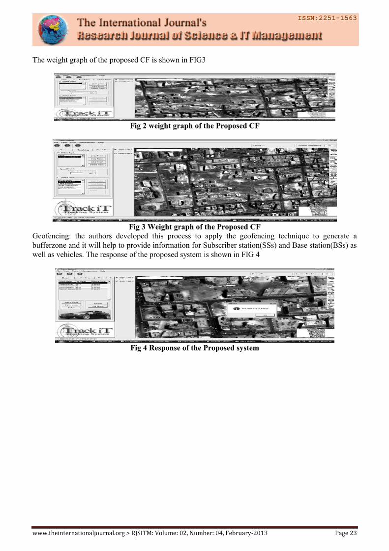
The weight graph of the proposed CF is shown in FIG3
Fig 2 weight graph of the Proposed CF
Fig 3 Weight graph of the Proposed CF
Geofencing: the authors developed this process to apply the geofencing technique to generate a
bufferzone and it will help to provide information for Subscriber station(SSs) and Base station(BSs) as
well as vehicles. The response of the proposed system is shown in FIG 4
Fig 4 Response of the Proposed system
www.theinternationaljournal.org > RJSITM: Volume: 02, Number: 04, February-2013 Page 24
Management phase(database): the management phase contains functions of organizing drivers
information, received data from the Base station(BS)/Subscriber station(SSs)(tracking data) and GIS
data(check-points).
This phase was built using microcontroller database
1) User tab: the user tab contains drivers(vehicles) information, with functions like ‘add’, ‘edit
‘and delete concerned with the drivers information. The reports button allow browsing reports for
available drivers.
2) Tracking tab: this tab contains the core of the system, which is divided into ‘online tracking’
as shown in FIG 7.
Online tracking: online tracking implements the interface between both connection ID(CID) such as
SS/BS and vehicles. This part is concerned with tracking real time data of vehicle positions, where the
data received from the BSs/SSs are displayed directly on the related map in the vehicle in front of the
driver seat.
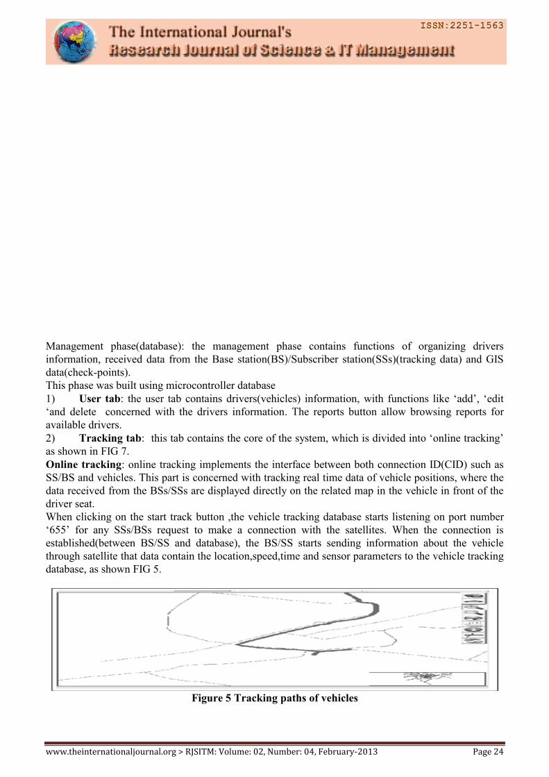
When clicking on the start track button ,the vehicle tracking database starts listening on port number
‘655’ for any SSs/BSs request to make a connection with the satellites. When the connection is
established(between BS/SS and database), the BS/SS starts sending information about the vehicle
through satellite that data contain the location,speed,time and sensor parameters to the vehicle tracking
database, as shown FIG 5.
Figure 5 Tracking paths of vehicles
www.theinternationaljournal.org > RJSITM: Volume: 02, Number: 04, February-2013 Page 25
Next fold is to find the QOS between CSs and TSs in a MAC frame information(e.g burst profile)
residing in the CL may be reduced to the mapping information between the CS and its corresponding
TS. The BS only specifies the burst profiles for the SSs which are only scheduled on the CL. For
example as shown that CSi is scheduled as the corresponding CS of TSi, where 1<=j<=k. when TSi has
untracked vehicle , it performs our protocols. If CSi receives the message sent from TSi, it starts to
transmit data about vehicle by using the agreed burst profile. The burst profile of a CS is resided on
either the UL map if the CS is also scheduled on CL. Our Proposed scheme is presented into: the
scheduling algorithm. The scheduling algorithm helps the BS to schedule a CS for each TS.
5. SCHEDULING ALGORITHM:
Assume Q represents the set of SSs serving non-real time connections (i.e., nrtPS or BE connections)
and T is the set of TSs. Due to the feature of TDD that the UL andDL operations cannot be performed
simultaneously, we cannot schedule the SS which UL transmission interval is overlapped with the
target TS. For any TS, St, let Ot bethe set of SSs which UL transmission interval overlaps with that of
St in Q. Thus, the possible corresponding CS of St must be in Q−Ot. All SSs in Q−Ot are consideredas
candidates of the CS for St. A scheduling algorithm, called Priority-based Scheduling Algorithm
(PSA), shown in Algorithm is used to schedule a SS with the highest priority as the CS. The priority
of each candidate is decided based on the scheduling factor (SF) defined as the ratio of the current
vehicle tracking request (VTR) to the current tracked vehicle. The SS with higher SF has more priority
to track that vehicle. Thus, we give the higher priority to those SSs vehicles. The highest priority is
given to the SSs vehicles with zero CG. Non real-time connections include nrtPS connections should
have higher priority the BE connections because of the QOS requirements. The priority of vehicles of
CSs is concluded with high to low as:nrtPS with zero CG,BE with Zero CG,nrtps with non-zero
CGand BE with Non zero CG. If there are more than one than SS vehicle with highest priority, we
select one with the largest CR as the CS in order to decrease the probability of overflow.
6. ANALYSIS:
The percentage of potentially tracking un tracked vehicles occupied in the tracked vehicles SS is
critical for the potential performance gain of our scheme. We investigate this percentage on network
traffics which is popularly used today. Additionally In our scheme each TS should transmit a RM to
inform its corresponding CS when it has tracking untracked vehicles at SS. However , the transmission
range of the the TS may not be able to cover the corresponding CS. It depends on the location and the
transmission power of the TS. It is possible that the un tracked vehicles cannot be tracked because the
CS does not not receive the RM. Therefore the benefit of our scheme is reduced. In this section, we
analze mathematically the probability of a CS to receive a RM successfully obviously
Algorithm 1 Priority-base Scheduling algorithm
Input: T is the set of TSs scheduled on the UL map.
Q is the set of SSs scheduled on the non-realtime applications.
Output: Schedule CSs for all TSsin T.
For i=1 to ║T║do
a.St TSi
b. Qt Q--- Ot
c. Calculate the SF for each SS in Qt
d. IF Any SS € Qt has zero granted bandwidth,
IF ANYSSs have nrtPS traffics and zero granted
Bandwidth
Choose one running nrtPS traffics with largestCR.
Else
www.theinternationaljournal.org > RJSITM: Volume: 02, Number: 04, February-2013 Page 26
Choose one with largest SF and CR.
e. Schedule the SS ad the corresponding CS of St
End For
This probability effects the vehicle tracking rate(VVR).VVR stands for the percentage of the un
tracked vehicles which is not tracked. Moreover the performance analysis is presented in terms of
through put gain (TG).
7. PERFORMANCE ANALYSIS OF PROPOSED SCHEME:
The traffic load in a network may vary dynamically.Thus, the network status can be classified into four
stages: light, moderate, heavy and fully loaded. Theperformance of the proposed scheme may be
variant indifferent stages. We investigate the performance of ourscheme in each stage. Suppose Ball
represents the total tracked vehicles supported by the BS. Assume represents the vehicle tracked by real
time connections and VTrt is the number of additional vehicles tracked by them via VTRs
{
i−1
}
Where max {0;Qnrt i−1−Wnrt i−1} (1)
}
is the amount of queued vehiclesarriving before frame i − 1. Since Yi−1 cannot be negative, the
probability of the CS, denoted as Su, which has data to calculate the recalculate bandwidth can be
obtained as:
Pu(u) =∫γ nrt max
P(X)dX Yi−1 (2)
where _nrt max is the maximal amount of non-real time vehicles arriving in a frame and vehicles
occupying. A CS which retraces the untracked vehicles successfullywhile receiving a RM must be
scheduled on the CS and have non-real time data to be transmitted and retraced. From equations (1)
and (2), the probability that a CS satisfies these two conditions is derived as:
║Qn║
based on the three metrics: 1) Throughput gain (TG):It represents the percentage of throughput which
is improved by implementing our scheme. The formal definition can be expressed as:
TG =TTracks− Tnotracks
where Tretraces and Tnoretraces represent the throughput with and without implementing our scheme,
respectively. The higher TG achieved shows the higher performance that our scheme can make.2)
Tracking untracked vehicle rate (VVR):It is defined as the percentage of the untracked vehicles
occupied in the total identified vehicles in the system without using vehicle retracking.
VVR =Vtracks Vuntracks
1) Throughput gain (TG):
TG= pretracked VT
Vg-VT
Suppose Vg is the total tracked vehicles in the system and the un tracked vehicles of the system is VT.
by equation , the total throughput gain, is solved. Delay is a critical factor affecting the QOS of
services. IN our scheme, we preserve the existing vehicle tracking. Moreover the CS cannot track the
vehicles until receiving the RM which is sent by TS
8. CONCLUSION:
It is very challenging task for SSs to predict the arriving vehicles precisely. Although the existing
system allows the SS vehicles to adjust the tracked vehicles via risk of failing to satisfy the QOS
requirements. Our research does focuses on proposed vehicle tracking system to track the untracked
vehicles once it occurs with improving quality. It allows the BS to schedule a complementary station
www.theinternationaljournal.org > RJSITM: Volume: 02, Number: 04, February-2013 Page 27
monitors the entire UL transmissions interval of its corresponding TS and stand by for any
opportunities to track the untracked vehicles. If we are observing the tracking system has the ability to
trace and co-ordinate a fleet of vehicles, with integration of BS(satellite)/SS(cell tower) technology. It
ensures that the tracking process is within an accurate and acceptable range, since it allows managers to
supervise vehicle status(i.e fuel, temperature). This proposed system can be used in monitoring and
controlling applications. But it is difficult task to connect in hill stations. Signal strength will not be
good in hill stations.
9. REFERENCES:
1) Real Time Web based VehicleTrackingusing GPS. Full Text Available By: Mukesh, P. R.
World Academy of
Science, Engineering & Technology. Jan2010, Vol. 61, p91-99. 9p. 4 Color Photographs, 12 Diagrams.
2) Design of a stable controller for accurate path tracking of automated guided
vehiclessystems.Full Text Available By: Kuttolamadom, Mathew; Mehrabi, Mostafa G.; Weaver, J.
International Journal of Advanced Manufacturing Technology. Oct2010, Vol. 50 Issue 9-12, p1183-
1188. 6p. 3 Diagrams, 1 Chart, 5 Graphs. DOI: 10.1007/s00170-010-2569-7.
3) Development of a vehicle image-tracking system based on a long-distance detection algorithm.
Full Text AvailableBy: Oh, Jutaek; Min, Joonyoung; Choi, Eunsoo. Canadian Journal of Civil
Engineering. Nov2010, Vol. 37 Issue 11, p1395-1405. 10p. 5 Color Photographs, 2 Black and White
Photographs, 3 Diagrams, 5 Charts.
4) Automatic vehicle location trackingsystem based on GIS environment. Full Text AvailableBy:
Aloquili, O.; Elbanna, A.; Al-Azizi, A. IET Software. Aug2009, Vol. 3 Issue 4, p255-263. 9p. 9 Black
and White Photographs, 6 Diagrams, 5 Charts, 1 Map. DOI: 10.1049/iet-sen.2008.0048.
5) Onboard vehicle detection and tracking using boosted Gabor descriptor and sparse
representation. AvailableBy: Yang, S.; Xu, J.; Wang, M.H. Electronics Letters. 8/2/2012, Vol. 48
Issue 16, p995-997. 3p. 1 Color Photograph, 2 Charts, 2 Graphs. DOI: 10.1049/el.2012.1922.
6) Data communication and automatic vehicle location
system “GPS-AVL”, (Alsi-Asia-page Ltd., 2004)
7) IEEE 802.16WG, ”IEEE standard for local and metropolitan area networks part 16: Air
interface for fixed and mobile broadband wireless access systems, Amendment 2,” IEEE 802.16
Standard, December 2005.
8) Jianhua He, Kun Yang and Ken Guild ”A Dynamic Bandwidth Reservation Scheme for Hybrid
IEEE 802.16 Wireless Networks” ICC’08 p.2571-2575.
9) Eun-Chan Park, Hwangnam Kim, Jae-Young Kim, Han-Seok Kim ”Dynamic Bandwidth
Request-Allocation Algorithm for Real-time Services in IEEE 802.16 Broadband Wireless Access
Networks”, INFOCOM 2008,p.852 - 860
Thomas G. Robertazzi ”Computer Networks and Systems:Theory and Performance Evaluation.”
Springer-Verlag 1990
10) Eun-Chan Park, Hwangnam Kim, Jae-Young Kim, Han-Seok Kim”Dynamic Bandwidth
Request-Allocation Algorithm for Real-time Services in IEEE 802.16 Broadband Wireless Access
Networks”,INFOCOM 2008,p.852 - 860
11) Frank H.P. Fitzek, Martin Reisslein, ”MPEG–4 H.263 Video Traces for Network Performance
Evaluation”, IEEE Network, Vol.15, No. 6, p.40- 54 November/December 2001
12) Stereo Visual Tracking Within Structured Environments for Measuring Vehicle Speed.Detail
Only AvailableBy: Zhu, Junda; Yuan, Liang; Zheng, Yuan F.; Ewing, Robert L. IEEE Transactions on
Circuits &Systems for Video Technology. Oct2012, Vol. 22 Issue 10, p1471-1484. 14p. DOI:
10.1109/TCSVT.2012.2202074.