Embed Size (px)
Citation preview

IMPROVING THE EFFICIENCY AND EFFECTIVENESS OF RAILCAR SAFETY APPLIANCE INSPECTIONS USING MACHINE VISION TECHNOLOGY
BY
JOHN RILEY EDWARDS
B.E., Vanderbilt University, 2004
THESIS
Submitted in partial fulfillment of the requirements
for the degree of Master of Science in Civil Engineering in the Graduate College of the
University of Illinois at Urbana-Champaign, 2006
Urbana, Illinois

ii
iii
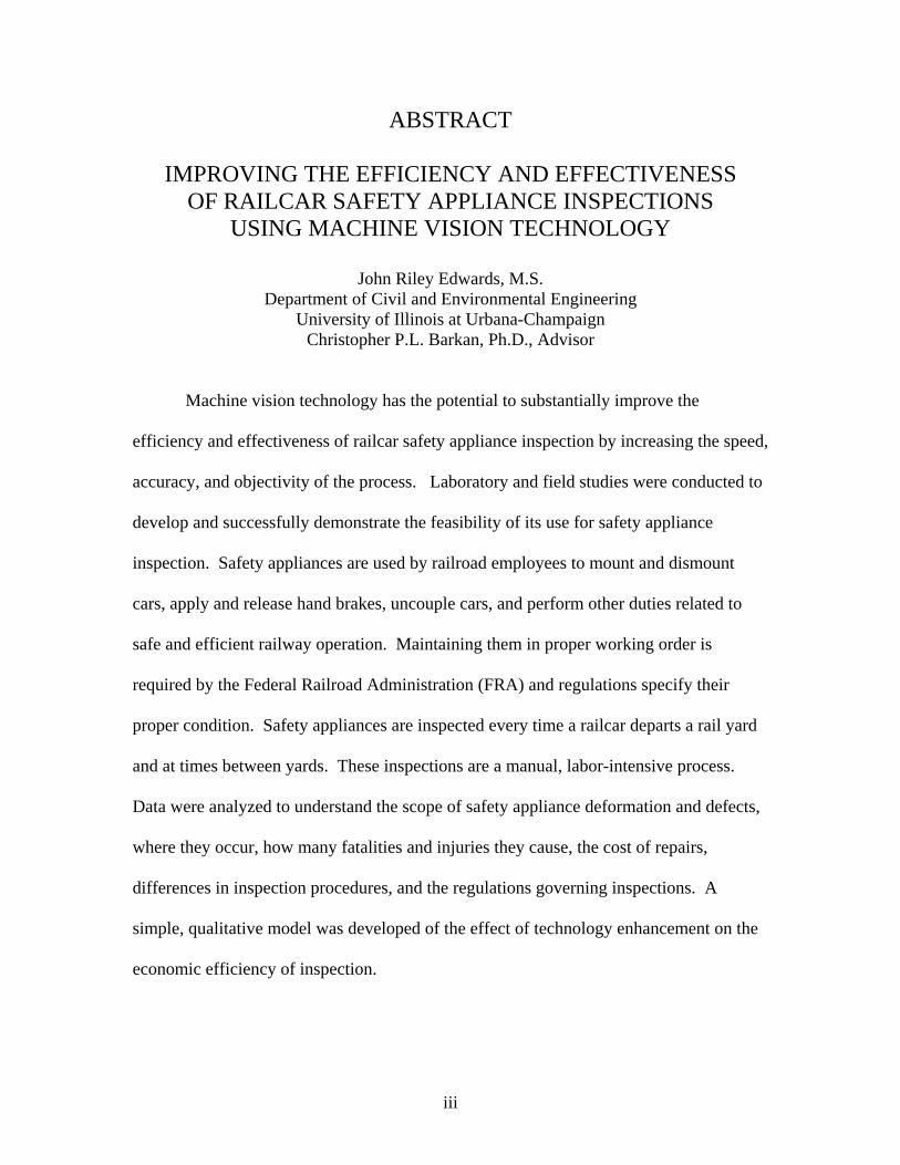
ABSTRACT
IMPROVING THE EFFICIENCY AND EFFECTIVENESS OF RAILCAR SAFETY APPLIANCE INSPECTIONS
USING MACHINE VISION TECHNOLOGY
John Riley Edwards, M.S. Department of Civil and Environmental Engineering
University of Illinois at Urbana-Champaign Christopher P.L. Barkan, Ph.D., Advisor
Machine vision technology has the potential to substantially improve the
efficiency and effectiveness of railcar safety appliance inspection by increasing the speed,
accuracy, and objectivity of the process. Laboratory and field studies were conducted to
develop and successfully demonstrate the feasibility of its use for safety appliance
inspection. Safety appliances are used by railroad employees to mount and dismount
cars, apply and release hand brakes, uncouple cars, and perform other duties related to
safe and efficient railway operation. Maintaining them in proper working order is
required by the Federal Railroad Administration (FRA) and regulations specify their
proper condition. Safety appliances are inspected every time a railcar departs a rail yard
and at times between yards. These inspections are a manual, labor-intensive process.
Data were analyzed to understand the scope of safety appliance deformation and defects,
where they occur, how many fatalities and injuries they cause, the cost of repairs,
differences in inspection procedures, and the regulations governing inspections. A
simple, qualitative model was developed of the effect of technology enhancement on the
economic efficiency of inspection.

iv
Extensive development and field testing was conducted of a digital video
acquisition system that enabled collection of images suitable for analysis using machine
vision algorithms. Camera angles were studied to determine the optimal view that
maximized the utility of the images while minimizing the number of cameras required to
analyze ladders, handholds, and brake wheels on high-sided gondolas and hopper cars.
Safety appliances were experimentally damaged on a railcar at the Transportation
Technology Center (TTC). The car was operated in a test train and digital images
acquired in a manner similar to how a permanent field installation would function. The
image acquisition system successfully detected the pertinent safety appliances as well as
deformations and FRA defects. The machine vision algorithms were found to be
sensitive to lighting conditions and it is likely that some means of controlling these will
be required for permanent installations.
It is anticipated that visual learning will be used to develop the algorithms that
detect deformations and defects and a very large number of images will be needed to
train the algorithm. Instances of safety appliance deformation, and especially defects, are
relatively uncommon on actual railcars; therefore, a virtual, three-dimensional model of a
railcar and its safety appliances was developed using 3DS MAX 8 to create images. The
model enables virtual deformation of any part of the car, as well as manipulation of
lighting conditions, camera viewing angle, and background conditions, thereby
expediting development of the algorithms and enabling testing of various approaches to
image acquisition.

v
An interim system for safety appliance inspection is considered that would enable
railroads to derive some of the benefits of machine vision inspection prior to complete
development of all of the algorithms necessary to inspect all appliances on all cars.
Finally, safety appliance regulations are considered as they relate to machine vision
inspection of safety appliances compared to visual inspection and a preliminary
assessment of the issues and requirements for automated inspection of other safety
appliances is presented.

vi
To
John and Paula Edwards

vii
ACKNOWLEDGEMENTS
I would like to thank all of the people who have encouraged me to pursue a career
in the railroad industry as well as those who have made this thesis possible. I am grateful
to David Davis, Jim Robeda, Jim Lundgren and Joseph LoPresti of Transportation
Technology Center, Inc., Pat Ameen of AAR, Bill Blevins, Darrel Hoyt, and Mike Smith
of CN, Ryan Miller, Paul Gabler, Larry Milhon, and Hank Lees of BNSF, Gary Nelson,
John Sigler, Todd Comer, Bruce King, and Hayden Newell of Norfolk Southern, Steve
Phebus and Mike Cipriani of CSX, Tom Dalrymple of Trinity Rail, and Dr. Narendra
Ahuja, Sinisa Todorovic, John M. Hart, Ze Ziong Chua, Nick Kocher, and John Zeman
of the University of Illinois for their assistance and cooperation with the research that
went into the preparation of this thesis. Principal support for this research was from the
Association of American Railroads Technology Scanning Program. Additional support
was provided by the BNSF Railway Technical Research and Development program. I
am grateful to CN for supporting me for the year 2004-2005 with a CN Railroad
Research Fellowship.
I am grateful to my classmates for their advice and time regarding this thesis as
well as their friendship over the past two years. I would also like to think my advisor, Dr.
Chris Barkan, for his encouragement and guidance throughout this research project.
Finally, I am also grateful to my parents, who allowed our family vacations and other
family time to be tailored around my love of transportation.

viii
TABLE OF CONTENTS
LIST OF TABLES........................................................................................................... xiii
LIST OF FIGURES ......................................................................................................... xiv
CHAPTER 1: INTRODUCTION........................................................................................1
1.1 Background on Railroad Safety Appliances and Safety Appliance
Inspection.........................................................................................................................1
1.2 History of Railroad Safety Appliances ......................................................................3
CHAPTER 2: QUANTIFICATION OF APPLIANCE DEFECT TYPES AND
OCCURANCE...................................................................................................................10
2.1 Quantification Methods ...........................................................................................10
2.2 FRA Inspection Database ........................................................................................11
2.3 Class I Railroad Bad Order Data .............................................................................13
2.4 AAR Repair Data.....................................................................................................19
2.5 FRA Casualty Database ...........................................................................................20
2.6 FRA Accident Database...........................................................................................21
2.7 Switching Operations Fatality Analysis Data..........................................................22
2.8 Opportunity Costs Due to Cars Being Out of Service .............................................24
2.9 Summary of Safety Appliance Data ........................................................................25
CHAPTER 3: RAILROAD CAR INSPECTIONS............................................................26
3.1 Introduction..............................................................................................................26
3.2 Car Inspectors ..........................................................................................................26
3.3 Inspection Duration..................................................................................................27
3.3.1 FRA Estimate of Inbound Inspection Duration ................................................27
3.3.2 Class I Railroad Estimate of Inspection Duration............................................29
3.3.3 AAR Estimate of Inspection Duration...............................................................29
3.3.4 Summary of Inspection Duration Estimates .....................................................29
3.4 Inspection Cost ........................................................................................................30
3.5 Regulations Governing the Inspection and Repair of Railcars................................30
3.5.1 FRA CFR Part 215 – The Freight Car Safety Standards .................................32
3.5.2 FRA CFR Part 231 – The Railroad Safety Appliance Standards .....................33
ix
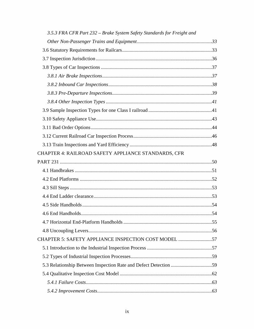
3.5.3 FRA CFR Part 232 – Brake System Safety Standards for Freight and
Other Non-Passenger Trains and Equipment............................................................33
3.6 Statutory Requirements for Railcars........................................................................33
3.7 Inspection Jurisdiction .............................................................................................36
3.8 Types of Car Inspections .........................................................................................37
3.8.1 Air Brake Inspections........................................................................................37
3.8.2 Inbound Car Inspections...................................................................................38
3.8.3 Pre-Departure Inspections................................................................................39
3.8.4 Other Inspection Types .....................................................................................41
3.9 Sample Inspection Types for one Class I railroad ...................................................41
3.10 Safety Appliance Use.............................................................................................43
3.11 Bad Order Options .................................................................................................44
3.12 Current Railroad Car Inspection Process...............................................................46
3.13 Train Inspections and Yard Efficiency ..................................................................48
CHAPTER 4: RAILROAD SAFETY APPLIANCE STANDARDS, CFR
PART 231 ..........................................................................................................................50
4.1 Handbrakes ..............................................................................................................51
4.2 End Platforms ..........................................................................................................52
4.3 Sill Steps ..................................................................................................................53
4.4 End Ladder clearance...............................................................................................53
4.5 Side Handholds ........................................................................................................54
4.6 End Handholds.........................................................................................................54
4.7 Horizontal End-Platform Handholds .......................................................................55
4.8 Uncoupling Levers...................................................................................................56
CHAPTER 5: SAFETY APPLIANCE INSPECTION COST MODEL ...........................57
5.1 Introduction to the Industrial Inspection Process ....................................................57
5.2 Types of Industrial Inspection Processes.................................................................59
5.3 Relationship Between Inspection Rate and Defect Detection .................................59
5.4 Qualitative Inspection Cost Model ..........................................................................62
5.4.1 Failure Costs.....................................................................................................63
5.4.2 Improvement Costs............................................................................................63

x
5.4.3 Total Costs ........................................................................................................65
5.5 Qualitative Inspection Cost Model after the Addition of New
Technologies to the Inspection Process .........................................................................66
CHAPTER 6: METHODS OF IMPROVING THE EFFICIENCY AND
EFFECTIVENESS OF RAILROAD SAFETY APPLIANCE INSPECTIONS ...............68
6.1 Machine Vision Overview.......................................................................................68
6.2 Comparison of Human Vision and Machine Vision................................................69
6.3 Automation and Memory.........................................................................................70
CHAPTER 7: MACHINE VISION SYSTEM FOR THE DETECTION OF
SAFETY APPLIANCE DECECTS...................................................................................72
7.1 Machine Vision System Locational Requirements..................................................72
7.2 Camera View ...........................................................................................................75
7.2.1 Perpendicular Side View...................................................................................75
7.2.2 Perpendicular Overhead View..........................................................................76
7.2.3 Angled Overhead View .....................................................................................77
7.2.4 Angled Side View ..............................................................................................78
7.2.5 Upward Angled Side View ................................................................................79
7.3 Camera Angle ..........................................................................................................81
7.4 Image Acquisition System.......................................................................................84
7.5 Machine Vision Algorithm ......................................................................................85
7.6 Frame Rate and Train Speed....................................................................................90
7.7 Methods for Obtaining Images of Deformed Railcar Safety Appliances................92
7.7.1 Manual Deformation of Railcar Safety Appliances ..........................................92
7.7.2 Three Dimensional Modeling of Railcar Safety Appliances.............................92
7.8 Challenges and Considerations in using Machine Vision to Inspect
Safety Appliances ..........................................................................................................96
7.9 Other Methods of Detecting Safety Appliance Defects...........................................98
7.9.1 Comparison of Opposite Corners .....................................................................98
7.9.2 Analysis of Shadows to Determine Ladder Rung and Handhold
Clearance.................................................................................................................101
7.10 Future Work Prioritization...................................................................................102
xi
7.10.1 Prioritization of Additional Safety Appliances .............................................102
7.10.2 Prioritization of Additional Car Types .........................................................102
CHAPTER 8: INTERIM APPROACH TO MACHINE VISION
INSPECTION OF RAILCAR SAFETY APPLIANCES ................................................106
8.1 Overview of Interim System..................................................................................106
8.2 Installation .............................................................................................................106
8.3 Image Analysis ......................................................................................................108
CHAPTER 9: SAFETY APPLIANCE PARAMETERS FOR MACHINE
VISION DETECTION.....................................................................................................112
9.1 Overview of Parameters.........................................................................................112
9.2 Handbrake..............................................................................................................114
9.2.1 Handbrake Design Parameters (FRA 2004b).................................................115
9.2.2 Brake Wheel Dynamic Parameters (FRA 2004b) ...........................................117
9.2.3 Brake Wheel Machine Vision Image Considerations .....................................117
9.3 Brake Step..............................................................................................................120
9.3.1 Brake Step Design Parameters (FRA 2004b) .................................................120
9.3.2 Brake Step Dynamic Parameters (FRA 2004b) ..............................................122
9.3.3 Brake Step Machine Vision Image Considerations ........................................122
9.4 Sill Steps ................................................................................................................125
9.4.1 Sill Step Design Parameters (FRA 2004b) .....................................................126
9.4.2 Sill Step Dynamic Parameters (FRA 2004b) ..................................................127
9.4.3 Sill Step Machine Vision Image Considerations.............................................127
9.5 Ladders...................................................................................................................130
9.5.1 Ladder Design Parameters (FRA 2004b) .......................................................130
9.5.2 Ladder Dynamic Parameters (FRA 2004b) ....................................................132
9.5.3 Ladder Machine Vision Image Considerations ..............................................132
9.6 Side Handholds ......................................................................................................134
9.6.1 Side Handhold Design Parameters (FRA 2004b)...........................................134
9.6.2 Side Handhold Dynamic Parameters (FRA 2004b)........................................135
9.6.3 Side Handhold Machine Vision Image Considerations ..................................135
9.7 Horizontal End Handholds.....................................................................................137
xii
9.7.1 Horizontal End Handhold Design Parameters (FRA 2004b).........................137
9.7.2 Horizontal End Handhold Dynamic Parameters (FRA 2004b)......................139
9.7.3 Horizontal End Handhold Machine Vision Image Considerations ................139
9.8 Vertical End Handholds.........................................................................................140
9.8.1 Vertical End Handhold Design Parameters (FRA 2004b) .............................140
9.8.2 Vertical End Handhold Dynamic Parameters (FRA 2004b) ..........................140
9.8.3 Vertical End Handhold Machine Vision Image Considerations.....................140
9.9 Uncoupling Levers.................................................................................................141
9.9.1 Uncoupling Lever Design Parameters (FRA 2004b)......................................141
9.9.2 Uncoupling Lever Dynamic Parameters (FRA 2004b)...................................142
9.9.3 Uncoupling Lever Machine Vision Image Considerations .............................142
9.10 End Ladder Clearance..........................................................................................143
9.10.1 End Ladder Clearance Design Parameters (FRA 2004b) ............................143
9.10.2 End Ladder Clearance Dynamic Parameters (FRA 2004b).........................143
9.10.3 End Ladder Clearance Machine Vision Image Considerations ...................144
CHAPTER 10: CONCLUSION ......................................................................................145
10.1 Summary..............................................................................................................145
10.2 Future Research and Issues..................................................................................146
REFERENCES ................................................................................................................148
APPENDICES .................................................................................................................152
APPENDIX A – Inbound Car Inspection Priorities ....................................................152
xiii
LIST OF TABLES Table 2.1 Safety appliance bad order symbols for one Class I railroad ............................19
Table 2.2 Summary of Safety Appliance Defect Data.......................................................25
Table 3.1 Inspection types and corresponding inspection symbols for an
example Class I railroad.............................................................................................41
Table 3.2 Data from one Class I railroad yard representing parameters that are
monitored with respect to the car inspection process ................................................43
Table 6.1 Comparison of relative advantages and disadvantages of human and
machine vision (Batchelor 2005) ...............................................................................70
Table 7.1 Summary table of views considered in photographing safety
appliances...................................................................................................................81
Table 7.2 Car Types and Codes showing the average number of passes by a
WILD site between October 2004 and November 2005..........................................104
xiv
LIST OF FIGURES Figure 1.1 Picture of the end of a covered hopper car showing the safety
appliances: sill step, side and end ladder, brake step, side and end
handholds, and the brake wheel ...................................................................................1
Figure 2.1 FRA safety appliance defects found by FRA inspectors between
1995 and 2004 grouped by major rule of CFR Part 231............................................12
Figure 2.2 Safety appliance defect ratios from FRA safety appliance inspections
for the ten year period of 1995-2004 .........................................................................13
Figure 2.3 Comparisons of FRA and Class 1 railroad safety appliance defects
by car type..................................................................................................................15
Figure 2.4 Comparison of safety appliance defects at two Class 1 railroad yards ............16
Figure 2.5 Distribution of safety appliance bad order rates at 60 locations on
one Class I railroad ....................................................................................................17
Figure 2.6 Specific appliances bad ordered on one Class I railroad during
October and November of 2005.................................................................................18
Figure 3.1 Comparison of the percentage of cars inspected by each inspection
type at two Class I railroad yards...............................................................................42
Figure 3.2 Bad order card for a sample Class I railroad ....................................................45
Figure 3.3 Three different approaches to inspection at three Class I rail yards.................47
Figure 5.1 Functional relationship between percent of defects escaping detection
and inspection rate of a human inspecting using 100% inspection
(Kennedy and Andrews 1977) ...................................................................................61
Figure 5.2 Qualitative model of optimum inspection costs as inspections are
currently performed (P0 and C0) (Kennedy and Andrews 1977) ...............................65
Figure 5.3 Qualitative model of optimum inspection costs after the addition of
additional technology to safety appliance inspections (P1 and C1) (adopted
from Kennedy and Andrews 1977)............................................................................67
Figure 7.1 Perpendicular view of the railcar......................................................................76
Figure 7.2 Perpendicular overhead view of a railcar .........................................................77
Figure 7.3 Angled overhead view of a railcar....................................................................78
Figure 7.4 Angled side view of railcar...............................................................................79

xv
Figure 7.5 Upward angled side view or railcar representing the optimal angle
for viewing ladder, handholds, and the brake wheel..................................................80
Figure 7.6 Optimal camera angle relative to the track for the inspection of
safety appliances using machine vision technology ..................................................82
Figure 7.7 Angle representing the physical location of the
camera beneath the top of rail ....................................................................................82
Figure 7.8 Critical angles in locating the camera for machine vision inspection
of safety appliances....................................................................................................83
Figure 7.9 Temporary portable field setup for machine vision collection of
safety appliance images .............................................................................................84
Figure 7.10 Image sequence for one corner of a railcar showing, A) an image
taken too early, B) at the optimal time, and C) too late .............................................85
Figure 7.11 Three primary steps in the perspective correlation process for an
image..........................................................................................................................87
Figure 7.12 Image of railcar after edge detection has taken place.....................................88
Figure 7.13 Detection of ladder rungs and handholds on the ............................................89
side and end of a railcar .....................................................................................................89
Figure 7.14 Additional examples of detected ladder rungs and handholds .......................89
Figure 7.15 Brake-wheel detection; yellow indicates no exception and red
indicates deformation of the brake-wheel..................................................................90
Figure 7.16 Plan view showing the camera’s field of view and the length of
railcar captured during the imaging process ..............................................................91
Figure 7.17 Views of a railcar after deformation was inflicted in a controlled
environment (left) and the corresponding 3D model showing the
deformation (right).....................................................................................................94
Figure 7.18 Validation of algorithms on the model image which replicates the
deformation seen in the actual image in Figure 7.17 .................................................95
Figure 7.19 View of both the BL and AR corners of a covered hopper
demonstrating the ease as to which the two opposite corners can be
compared....................................................................................................................99
xvi
Figure 7.20 Example images before and after edge detection algorithms were
run on the image.......................................................................................................100
Figure 7.21 Example of overlayed BR and AL corners of a covered hopper car............101
Figure 7.22 Average number of visits to WILD sites between October 2004 and
November 2005........................................................................................................103
Figure 7.23 Car miles traveled by car type in 2004 (AAR 2005)....................................105
Figure 8.1 Camera views for interim machine vision installation of railcar
safety appliances ......................................................................................................107
Figure 8.2 View of the BL and AR corners of a hopper demonstrating the ease
of comparison of like elements of the safety appliances .........................................108
Figure 8.3 View of the BL and AR corners of a hopper showing no deformed
safety appliances ......................................................................................................109
Figure 8.4 View of the BR and AL corners of a hopper..................................................110
showing no deformed safety appliances ..........................................................................110
Figure 9.1 Images of the brake wheel..............................................................................114
Figure 9.2 Profile view of a common brake wheel design ..............................................115
Figure 9.3 Brake wheel parameters .................................................................................116
Figure 9.4 Additional brake wheel parameters ................................................................117
Figure 9.5 Brake wheel viewed from perpendicular to the track showing brake
wheel clearance ........................................................................................................118
Figure 9.6 Brake wheel with insufficient clearance per CFR Part 231 ...........................119
Figure 9.7 Example images of the brake step and brake wheel.......................................120
Figure 9.8 Brake step parameters.....................................................................................121
Figure 9.9 Additional brake step parameters ...................................................................121
Figure 9.10 Image of the brake step taken perpendicular to the tracks and in-
line with the brake step ............................................................................................122
Figure 9.11 Image of the brake step taken perpendicular to the tracks and above
the brake step showing the step’s length..................................................................123
Figure 9.12 End platform on a boxcar showing significant deformation ........................125
Figure 9.13 Sill step without additional rung...................................................................125
Figure 9.14 Sill step with additional rung........................................................................126

xvii
Figure 9.15 Sill step parameters.......................................................................................126
Figure 9.16 Sill step offset underneath the railcar ...........................................................127
Figure 9.17 Sill step viewed from shallow angle to show sill step deformation .............129
Figure 9.18 Sill step deformation showing an FRA defect (left) and significant
deformation (right)...................................................................................................129
Figure 9.19 Images of the side ladder (left) as well as an image of both the side
and end ladders (right) on open-top hopper cars......................................................130
Figure 9.20 Design and dynamic parameters for ladders on an open-top hopper
car.............................................................................................................................131
Figure 9.21 Additional design and dynamic parameters for ladders on an open-
top hopper car ..........................................................................................................132
Figure 9.22 Deformations of side and end ladders on a covered hopper car..................133
Figure 9.23 Deformations of the top side ladder rung on an open-top hopper car .........133
Figure 9.24 Side handholds on both the AL and BR corners of open-top hopper
cars ...........................................................................................................................134
Figure 9.25 Design and dynamic parameters for handholds of open-top hopper
cars ...........................................................................................................................135
Figure 9.26 Side handhold on an open-top hopper car showing less than the
required 2” clearance ...............................................................................................136
Figure 9.27 Side handholds clearance potentially affected by a piece of coal on
an open-top hopper car.............................................................................................136
Figure 9.28 View of both the AR and BR corners of the railcar showing the
horizontal end handholds on open-top coal cars......................................................137
Figure 9.29 Design and dynamic parameters for horizontal end handholds...................138
Figure 9.30 Additional design and dynamic parameters for horizontal end
handholds .................................................................................................................139
Figure 9.31 Example of an uncoupling lever...................................................................141
Figure 9.32 design and dynamic parameters for the uncoupling lever ............................142
Figure 9.33 Design and dynamic parameters for end ladder clearance ...........................144

1
CHAPTER 1: INTRODUCTION
1.1 Background on Railroad Safety Appliances and Safety Appliance Inspection
Safe and efficient movement of trains and execution of railroad employee duties
are critically important to the railroad industry. Consequently, any method of providing
additional productivity, efficiency, and safety benefits is of great interest to railroads.
Currently, before a train departs a rail yard it is inspected for a variety of defects,
including safety appliance defects. Safety appliances on railcars are the interface
between humans and rolling stock with regard to movement of railcars. They consist
primarily of handholds, sill steps, brake steps, ladders, running boards, uncoupling levers,
and the brake wheel (Figure 1.1).
Figure 1.1 Picture of the end of a covered hopper car showing the safety appliances: sill step, side and end ladder, brake step,
side and end handholds, and the brake wheel

2
Safety appliances have been required on railcars since 1893 when Congress
passed the Safety Appliance Act (ICC 1893). The Safety Appliance Act focused mostly
on the need for automatic couplers and power brakes but also called for what we now
consider safety appliances by requiring secure grab irons, or handholds, on cars (ICC
1893, White 1993). The objective was to provide railroad transportation employees with
a set of safe, standardized features to mount, dismount, and perform other functions that
required them to ride aboard the car. Safety appliances are currently regulated by the
Federal Government through the Railroad Safety Appliances Standards, Title 49 Code of
Federal Regulations (CFR) Part 231, that specify the location, number, material, and
means of securement of all safety appliances (FRA 2004b).
Safety appliances are inspected by railroad carmen primarily using visual cues
with some tactile and auditory means occasionally used for certain tasks. Carmen are
railroad employees who are trained to inspect cars for many types of defects that may
cause the car to be unsafe for movement. In addition to inspection, their duties include
repair and re-railing of railcars. Cars are inspected each time they are added to a train,
even though they may have satisfactorily passed multiple inspections prior to the current
one. Safety appliance inspections occur as a part of more encompassing railroad car
inspections. These inspections concentrate on air brakes, the car body, and brake systems
among many other mechanical aspects of the railcar. Much of the success of the current
inspection process is due to its redundancy. However, carmen inspect hundreds of cars
during their shift, and monotony and fatigue may affect the efficiency of inspections.
After carmen complete safety appliance inspections, the results are generally not
recorded, thus a railcar’s health cannot be tracked over time. This makes both planned

3
maintenance and monitoring defect trends difficult. Defect trends could be used as a
means of locating industries that consistently damage railcars, or be used to suggest
future design changes for railcar safety appliances.
Inspections are undertaken while inbound and outbound trains are on receiving
and departure tracks. Capacity in yards is increasingly at a premium, therefore improving
inspection efficiency also has the potential to increase yard throughput. One way that the
effectiveness and efficiency of safety appliance inspections can be increased is through
the implementation of machine vision technology. A machine vision system for safety
appliance inspection involves capturing digital video of a train as it passes and running
machine vision algorithms that identify the safety appliances on railcars and detect
defects.
Benefits to a machine vision system would come in several forms. A system of
this type would lead to better utilization of labor, more effective inspections, and
potentially improve utilization of yard space. The system should be able to categorize
defects in terms of the appropriate level of action required. The system would also lend
itself to development of a database for each car that would enable trends to be detected
and allow better planning and management of railcar maintenance.
1.2 History of Railroad Safety Appliances
In the latter part of the nineteenth century, railroads were considered one of the
most hazardous forms of employment (Wetzel 1977). In 1893, the annual fatality rate
among all railroad employees was 3.27 per thousand employees (Aldrich 1997). As a
means of comparison, bituminous mining had a fatality rate of 2.15 and anthracite
mining’s fatality rate was 3.00. In a 1913 mortality study investigating the effects of
4
occupation on mortality it was found that railroad work was more dangerous than most
other industries, including mining, with a death rate as much as nine times greater than
the average (Medico 1913). Some of the factors contributing to the hazards of railroad
work included a general lack of sufficient brakes, too few brakemen, problems with
timetable and train order operation, poor infrastructure, and differing operating conditions
from railroad to railroad (Aldrich 1997). The first casualty statistics were published by
the New York State Railroad Commission in the 1850s documenting the risks to railroad
employees, quantifying the number of employees killed, and generally drawing attention
to the unsafe conditions of the time (Aldrich 1997). Although there were safer
alternatives to the car designs of the day, retrofitting the thousands of railcars would have
been costly. As White (2005) put it, retrofitting the railcar fleet would have been more
costly than replacing trainmen.
As railroads, governments, and the public became more aware of the safety
problem, a group of railroad men, state commissioners, and reformers began to push for
the addition of automatic couplers and air brakes on freight cars to curtail the growing
number of fatalities and injuries. One of the reformers, Lorenzo S. Coffin, began a fight
to make trainmen’s jobs safer by speaking to groups of all types, culminating with
President Benjamin Harrison (White 2005). Coffin, who was a farmer and part time
preacher with no engineering background, changed opinions regarding the high capital
costs associated with upgrading railcars by playing on the national conscience (White
2005). On March 2, 1893, on the last day of President Harrison’s term, the United States
Congress passed the Safety Appliance Act in an effort to curtail the growing number of
accidents and fatalities suffered by railroad employees.

5
The Interstate Commerce Commission (ICC), which had been created six years
earlier with responsibility for economic regulation of railroads, now had safety added to
its responsibilities. Section 4 of the Safety Appliance Act of 1893 pertains to a subset of
what we now know of as safety appliances and stated: “that from and after the first day of
July, eighteen hundred and ninety-five, until otherwise ordered by the Interstate
Commerce Commission, it shall be unlawful for any railroad company to use any car in
interstate commerce that is not provided with secure grab irons or handholds in the ends
and sides of each car for greater security to men in coupling and uncoupling cars.” The
objective of the Safety Appliance Act of 1893 was to provide railroad transportation
employees with a set of safe, standardized features to mount, dismount and perform other
functions during transportation. The Safety Appliance Act of 1893 went beyond what we
consider safety appliances today by calling for automatic couplers, power brakes, and
other devices that would improve the safety of train make-up and operation for the
benefit of both employees and passengers. The act did not, however, specify the exact
parameters for safety appliances or their installation on the car body.
The ICC conducted safety appliance inspections with the primary goal of
identifying defective appliances covered by the law including; couplers, air brakes, draw
bar heights, and grab irons (Wetzel 1977). The 1909 report of the ICC noted that the law
is “too limited in its scope to afford the full measure of protection to which railroad
employees are entitled” (ICC 1909). By 1909, inspectors began reporting defects on
appliances other than those included under the 1893 act, including ladders, roof hand
holds, hand brakes, running boards, and sill steps (ICC 1909). The ICC had no
enforcement power over these additional appliances and could not penalize the railroads
6
for the using these appliances in a defective condition. At the time, the Masters Car
Builders Association (MCBA) maintained standard locations and forms of application for
all safety appliances regardless of whether or not they were covered under the law. The
MCBA was primarily comprised of mid-level railroad managers who were in charge of
the design, purchase, and repair of railcars (White 2005). Allowances for optional
methods of application of the MCBA standards were permitted and resulted in confusion
which “has been disastrous to hundreds of switchmen and other railroad employees”
(ICC 1909).
Even though the additional appliances were not covered under the law, their
condition was mentioned in the ICC Chief Safety Appliance Inspector’s annual report
(ICC 1909, Wetzel 1977). The additional defect information on the appliances not
covered under the law provided needed data to propose additional safety appliance
legislation. The 1909 Report of the ICC refers to the omission of these additional
appliances from the original law as a “defect” because “the additional appliances are
vitally necessary for the safety of employees.”
A bill that included the additional appliances (H.R. 26725) was passed by the
Senate in 1909 but failed to be reported in the Senate due to expiration of the session
(ICC 1909). The 1909 ICC report goes on to say that the bill “in no way advanced the
interest of any inventor or proprietor of a specific device” hinting that Congress may have
been skeptical of the bill’s intentions. The ICC (1909) notes the necessity of having
uniform equipment by saying that “it is of vital importance to employees that the
appliances designed for their safety shall be placed alike on all cars of the same class, so
that they may know with certainty, day or night, that they [trainmen] will always find

7
them in like positions and locations.” The 1909 ICC Report also notes that uniformity
was not achieved through voluntary actions of those who are responsible for the railcars
and the enforcement issue should be handled in the same manner as couplers, grab irons,
and power brakes – through an act of Congress.
On April 14, 1910 an act, hereafter referred to as the Safety Appliance Act of
1910, was passed requiring the number, dimensions, location, and manner of application
for safety appliances to be specified within six months for all safety appliances that were
named in both the 1893 and 1910 Acts with the objective of further decreasing the
number of injuries and fatalities of railroad workers (ICC 1910). This expanded group of
appliances included grab irons, ladders, sill steps, hand brakes, running boards, and other
similar equipment. In 1910, a joint committee representing the ICC, railroad employees,
and carriers met and agreed on safety appliance regulations. These regulations were
adopted on October 13, 1910 and served as the basis for the FRA regulations of today
(ICC 1910, FRA 2004a). By the terms of the Safety Appliance Act of 1910, the
recommendations were made standards for future observance (ICC 1910). The final date
of compliance for the Act of 1910 was set at July 1, 1911, a date which is still referenced
in today’s Railroad Safety Appliance Standards exempting certain cars built prior to this
date from certain sections of the Standards.
In understanding the overall scope of the Safety Appliance Acts it is interesting to
note a change in the ICC’s view of providing uniformity of safety appliances. At the
time of the Safety Appliance Act of 1893, the majority of ICC’s concern was focused on
power brakes and automatic couplers, with only a section of the Act being dedicated to
what we refer to today as safety appliances. By 1910 and 1911, the primary focus of the
8
ICC was the regulation of safety appliances as we now know them, with little mention in
the annual reports of those other appliances mentioned in the 1893 Act. Consequently,
the Acts and amendments of the time reflected this change.
Paralleling to the acts regulating safety appliances, railroads themselves began to
give safety greater importance as they came to recognize the implications of their
numerous incidents. In 1910, Ralph C. Richards of the Chicago and North Western
(C&NW) Railroad established the first railway safety organization (Aldrich 1992).
Richards was the general claims agent for the railroad, was familiar with accident
statistics, and was consequently appalled by the carnage of the day (Aldrich 1997).
Within two years of the inception of C&NW’s Safety First program, 40% of
American railroads had some type of safety organization according to the Central Safety
Committee of the C&NW Railroad. The reasoning behind this rapid conversion was
twofold; the fact that the initial effort by Richards at the C&NW gained a great deal of
positive public attention, and the fact that employers began to be liable for a greater
number of their employee’s injuries (Aldrich 1997). The 1908 Congress had changed
the Employer’s Liability Law that governed workers in interstate commerce by
abolishing the “fellow-servant” and “assumption-of-risk” defenses that had previously
provided protection to employers from liability associated with on-the-job injuries
(Aldrich 1997). Aldrich (1997) also notes that the unions began to use the mounting
number of casualties as a method of bargaining for wage increases resulting in railroad
management seeing the need for improved workplace safety.
In general, many aspects of the original Railroad Safety Appliance Act have
evolved into what is today known as The Railroad Safety Appliance Standards, which are

9
a part of the Federal Railroad Administration’s (FRA) Mechanical Standards. In 1967,
the FRA was created as a part of the newly formed U.S. Department of Transportation
(US DOT) and issued the current Railroad Safety Appliance Standards one year later
using the ICC orders of 1911 as a base (FRA 2004a). The last major modification of the
standards occurred in 1976 with the addition of two sections (§231.29 and §231.30)
relating to locomotives (FRA 2004a). As of 2005, there is ongoing work to update
certain sections of the Safety Appliance Standards pertaining to newer car types.
With the passage of the Federal Railroad Safety Act in 1970, the ICC’s authority
was transferred to the US DOT giving the secretary of transportation broad and general
regulatory powers over railroad safety (FRA 2001). This responsibility was delegated to
the FRA soon thereafter. Throughout this thesis the terms Title 49 CFR Part 231, 49
CFR Part 231, CFR Part 231, Part 231, and The Safety Appliance Standards will refer to
The Railroad Safety Appliance Standards.
10
CHAPTER 2: QUANTIFICATION OF APPLIANCE DEFECT TYPES AND OCCURANCE
2.1 Quantification Methods
I used two primary sources of data to quantify the occurrence of safety appliance
defects; data from FRA safety appliance inspections and Class I railroad bad order data.
Additionally, car repair data from the Association of American Railroads (AAR) were
used to estimate the magnitude of costs associated with safety appliance repairs. Data
from the FRA casualty and accident databases and information from the Switching
Operations Fatality Analysis (SOFA) Working Group were analyzed to understand how
many injuries and fatalities occur as a result of defective safety appliances. These data
served to answer several questions regarding the scope of safety appliance inspections
and the impact of safety appliance defects that escape detection. Some of the questions
addressed were:
• What is the percentage of cars inspected by FRA mechanical inspectors reported
to have defective safety appliances?
• What percentage of cars inspected by railroads are bad ordered due to safety
appliance defects?
• What is the percentage of cars inspected by railroads that have safety appliance
defects that are repairable in the yard without necessitating a bad order?
• How does the number of safety appliance bad orders vary between yards?
• How much money is spent by North American railroads on safety appliance
inspections?
11
• How much money is spent by North American railroads on safety appliance
repairs on cars in interchange service?
• How many fatalities and injuries are suffered by railroad employees as a result of
defective safety appliances?
• What is the opportunity cost associated with railcars being out of service for
safety appliance bad orders?
These questions and others will be addressed in this chapter.
2.2 FRA Inspection Database
The FRA maintains a database of all inspections conducted by both federal and
state inspectors. The data are grouped by specific part of the CFR and also by type of
inspector; state or local. The data for Part 231 are divided into major rules. Generally,
each major rule pertains to a specific safety appliance. In the case of ladder treads and
handholds, as many as four separate safety appliances are covered by one major rule.
Other appliances, such as the hand brake, are separated into three major rules. Analysis
of these data for the period 1995-2004 showed that 59% of defects occurred on ladder
treads, handholds, and sill steps (FRA 2005, Figure 2.1).

12
0%
10%
20%
30%
40%
50%
Ladd
er tre
ads a
nd ha
nd ho
ld
Sill ste
p
Uncou
pling
leve
r
Ladd
ers
Handra
il or s
afety
railin
g
Hand B
rake -
Whe
el
End P
latfor
m
Hand B
rake
Brake S
tep
Runnin
g Boa
rd
Platfor
m and s
witchin
g step
Draft A
ttach
ments
Hand B
rake -
gears
and r
etaine
r
Passe
nger
car s
ide do
or ste
p
Safety Appliance
Perc
enta
ge
Figure 2.1 FRA safety appliance defects found by FRA inspectors between 1995 and 2004 grouped by major rule of CFR Part 231
Between 1995 and 2003, 21% of Motive Power and Equipment (MP&E)
inspections focused on the safety appliances and accounted for 32% of the total defects
detected by MP&E inspectors. The defect rate, or percentage of defective units (railcars)
relative to the number of units inspected, is also given in the FRA database. The rate
varies from 5.4% to 7.4% for the years 1995-2004, averaging 6.6% (Figure 2.2). The rate
represents the number of defective railcars as a percentage of the total number of units
inspected and thus does not reflect multiple defects on a single car. For example, FRA
inspectors would flag approximately six cars of a 100-car train for defective safety
appliances, with each car having at least one defective appliance on it. These data are
important for comparing the difference between the rate that FRA inspectors find safety

13
appliance defects during MP&E inspections and the rate that railroads find safety
appliance defects while conducting car inspections.
0%
2%
4%
6%
8%
1995 1996 1997 1998 1999 2000 2001 2002 2003 2004
Year
Rat
io (D
efec
ts/U
nits
)
Figure 2.2 Safety appliance defect ratios from FRA safety appliance inspections for the ten year period of 1995-2004
2.3 Class I Railroad Bad Order Data
In order to determine the number of defects found by railroad carmen, an initial
analysis of bad order data was conducted for the fourth quarter of 2004 at two major
Class I railroad yards. According to one major North American railroad 2.5% of cars are
bad ordered due to mechanical defects during inbound car inspections. A large
percentage of these bad orders are related to the train’s brake system. Estimates from
mechanical personnel at a major western railroad place nearly 60% of bad orders in this
category. Safety-appliance-related bad orders make up approximately 10-25% of all bad
orders based on two Class I railroad estimates. Taken as a whole, the percentage of cars

14
bad ordered due to safety appliance defects was 0.30% and 0.85 % at the two Class I rail
yards initially studied in this project.
When calculating this percentage it is difficult to determine the denominator
representing the total number of cars that received safety appliance inspections. This is
because safety appliance defects are most likely to be found in a subset of inspection
types although they should be inspected during all railcar inspections per the Safety
Appliance Statute (see Statutory Requirements in Chapter 3). In the case of this analysis
I used only inbound inspections and air brake inspection car count numbers in the
denominator of the bad order rate since these are generally the inspections in which
safety appliance defects are the most likely to be identified. Other types of inspections
such as roll-by inspections and the lacing and bleeding of the train’s air line were
excluded from the calculation.
These safety appliance bad order numbers underestimate the actual occurrence of
defects because many cars are repaired in the yard without moving the car to the repair
track or facility. These repairs, called “Yard Repairs”, are repairs that are carried out by
carmen without the car being sent to the repair track and involve the use of graduated pry
bars and sometimes acetylene torches. One Class I railroad mechanical manager
estimated that as many as 75% of the safety appliance repairs were completed in this
way. In these cases there is no requirement to record the repair. One Class I railroad
chooses to report these repairs to an in-house database that includes non-AAR billable
repairs. If 0.30% to 0.85% of cars are bad ordered for safety appliance defects, and only
25% of safety appliance defects are actually bad ordered to the shop or repair facility, the
percentage of cars with safety appliance defects could be as much as four times higher

15
than the bad order numbers indicate. This would result in 1.2% to 3.4% of cars having
safety appliance defects, a figure somewhat closer to the FRA average of 6.6%.
In addition, the differences between the FRA defect rates and the railroad bad
order rates are the result of differing amounts of inspection scrutiny. FRA inspectors
spend considerably more time inspecting a railcar than do railroad carmen. They may
climb on and over a car, checking all the handholds and running boards, whereas railroad
carmen are not expected to, nor do they have time to, conduct such an intensive
inspection on a routine car inspection. The differences in percentage of safety appliance
defects between FRA and railroad car inspections are broken down by appliance in
Figure 2.3.
0%
10%
20%
30%
40%
50%
60%
Laddertreads andhand hold
Sill step Uncouplinglever
Ladders Handrail orsafetyrailing
Hand Brake- Wheel
RunningBoard
Platformand
switchingstep
Safety Appliance
Perc
enta
ge
FRA Example Railroad
Figure 2.3 Comparisons of FRA and Class 1 railroad safety appliance defects by car type

16
Interestingly, there are considerable differences between the distributions of
safety appliances defects in the two yards (Figure 2.4). In Yard A there are more sill
steps and operating lever defects whereas in Yard B over 35% of the defects are found on
crossover steps alone. According to management at one Class I railroad, the percentage
of safety appliance defects is affected by the amount of interchange traffic (Hoyt 2004,
Smith 2004). Another cause of the inter-yard variability in safety appliance defects is the
differing distribution of car types due to different yard and traffic make-up (Smith 2004,
Ameen 2006).
0%
5%
10%
15%
20%
25%
30%
35%
40%
UncouplingLever
Sill Step Hand Hold Crossoverand Step
Ladder Hand Rail /Cable
Hand BrakeWheel
RunningBoard
Safety Appliance
Perc
enta
ge
Yard A Yard B
Figure 2.4 Comparison of safety appliance defects at two Class 1 railroad yards
Additional analysis of one Class I railroad was undertaken to determine the
amount of inter-yard variability in safety appliance bad orders rates. Data were obtained
17
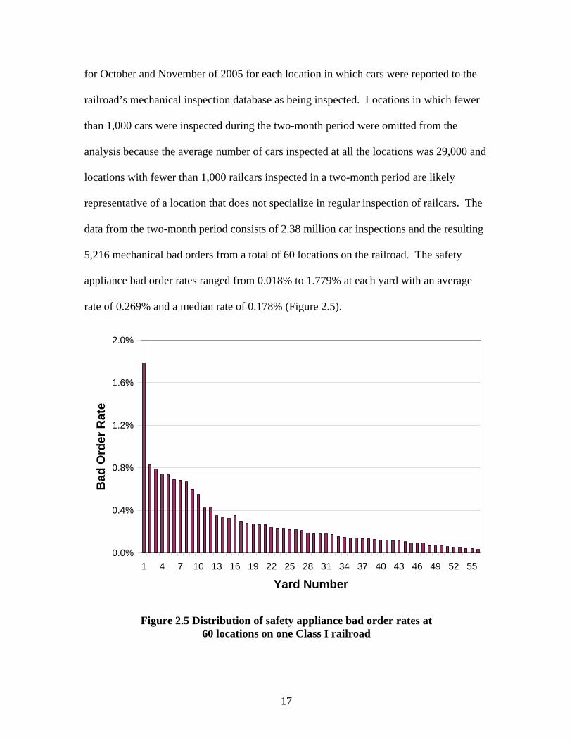
for October and November of 2005 for each location in which cars were reported to the
railroad’s mechanical inspection database as being inspected. Locations in which fewer
than 1,000 cars were inspected during the two-month period were omitted from the
analysis because the average number of cars inspected at all the locations was 29,000 and
locations with fewer than 1,000 railcars inspected in a two-month period are likely
representative of a location that does not specialize in regular inspection of railcars. The
data from the two-month period consists of 2.38 million car inspections and the resulting
5,216 mechanical bad orders from a total of 60 locations on the railroad. The safety
appliance bad order rates ranged from 0.018% to 1.779% at each yard with an average
rate of 0.269% and a median rate of 0.178% (Figure 2.5).
0.0%
0.4%
0.8%
1.2%
1.6%
2.0%
1 4 7 10 13 16 19 22 25 28 31 34 37 40 43 46 49 52 55
Yard Number
Bad
Ord
er R
ate
Figure 2.5 Distribution of safety appliance bad order rates at 60 locations on one Class I railroad

18
Using the estimate that only 25% of safety appliance defects result in the bad
ordering of the car, the number of cars with defective safety appliances is 1.076%. All
but one of the 60 locations has a bad order rate of less than 1.0% (Figure 2.5).
The relative frequency of safety appliance bad orders is also of interest (Figure
2.6, Table 2.1). The greatest percentage of safety appliance bad orders (21.7%) occurred
on the uncoupling lever and the fewest (1.0%) occurred on the hand brake wheel.
0%
5%
10%
15%
20%
25%
CL AH AS AL AC BH AR AB
Safety Appliance
Perc
enta
ge
Figure 2.6 Specific appliances bad ordered on one Class I railroad during October and November of 2005

19
Safety Appliance Bad Order SymbolLadder ALSill Step AS
Hand Hold AHHand Rail / Cable AR
Running Board ABCrossover and Step ACHand Brake Wheel BWUncoupling Lever CL
Table 2.1 Safety appliance bad order symbols for one Class I railroad
2.4 AAR Repair Data
AAR repair data were analyzed to determine the monetary value of safety
appliance repairs. In 2003, there were 195,242 repairs reported to AAR on ladders,
handholds, brake wheels, and uncoupling levers (AAR 2003a). This represents
$5,177,415 in repair costs billed to railroads and private car owners, or 1.35% of all
repairs made in interchange (AAR 2003a). This number substantially understates the
total cost of repairs made to safety appliances for several reasons. As mentioned above,
most such repairs are made, without a car being sent to a mechanical shop or repair track.
Additionally, the only repairs that are reflected in interchange data are those that
occur on railroad-owned cars that are on another (foreign) railroad’s property. Even if a
car is sent to a repair facility, a safety appliance repair is not billable under the AAR
Interchange Rules unless the safety appliance is replaced or removed for straightening
(AAR 2004). For instance, if a car is found to have a ladder rung not meeting the
clearance requirement of 49 CFR Part 231, the car will be bad ordered. The car will then
be repaired per the AAR’s Interchange Rules which, under Rule 79, state that no repairs
consisting of tightening or straightening are billable.
20
According to mechanical personnel at one Class I railroad, tightening and
straightening of handholds and ladder rungs represents a large number of repairs made by
railroads. In conclusion, AAR car-repair billing data may not reflect the full scope of
safety appliance defects as well as FRA and railroad safety appliance inspection data.
2.5 FRA Casualty Database
The FRA maintains an extensive casualty database; however, correlating
casualties to Safety Appliance violations is nontrivial. Casualties are reported using the
Railroad Injury and Illness Summary form (Form 6180.55a). Of all the fields on the form
only those relating to activities, locations, and cause of the incident aid in correlating a
safety appliance defect to a casualty.
Of the physical act circumstance codes describing the employee’s action when
they were hurt, eleven of them could be related to safety appliances. Examples would be
“getting on”, “getting off”, “applying handbrakes”, etc. Three location fields are listed
that refer to the “general location of the person at time of injury”, “type of on-track
equipment”, and the “specific location of person at time of injury”. Of the three, only the
“specific location of the person at time of injury” can aid in pointing the casualty to a
safety appliance defect, as the other two location fields are too broad because safety
appliance casualties can occur on most types of equipment in most “general” railroad
locations. In addition, codes must be selected to describe the “circumstance of the
event”, the “tools or objects involved”, and the “probable reason for the injury”.
In an attempt to link casualties to safety appliance defects, data from the period of
1999-2004 were analyzed. Prior to 1998 there are gaps in the data that do not allow for a
complete analysis of casualties associated with the safety appliances of a railcar. In
21
evaluating the number of incidents in which the codes can be traced to safety appliances,
only 19 of the 87 (22%) reports of casualty contained narrative fields that were filled out
making it difficult to draw any conclusions. Narrative fields provide descriptions of the
incidents and include information obtained by FRA inspectors from railroad employees.
An example narrative describing a 1998 incident is as follows; “dismounting car when
lower ladder rung gave way, causing him to lose grip falling to ground on tailbone”.
Many of the injuries occurred when a handhold or sill step gave out while an
employee was mounting a car. While these injuries occurred on a safety appliance,
oftentimes there is no mention within the narrative fields that the safety appliance was
actually defective at the time of injury. However, it seems likely that incidents in which
the appliance actually failed indicate an appliance that was probably not “securely
fastened” which is a violation of the regulations. Overall, the data in the casualty
database are not detailed enough to draw a correlation between safety appliance defects
and casualties.
2.6 FRA Accident Database
The FRA maintains an extensive database on all railroad accidents that result in
damage over a certain monetary threshold. After identifying variables that relate to
safety appliances and evaluating the data, I determined that none of the accidents could
be correlated to defective safety appliances. There is a possibility that coupler mismatch
derailments may occur as a result of incorrect drawbar height, but these derailments seem
to be caused by many other contributing factors.

22
2.7 Switching Operations Fatality Analysis Data
The Switching Operations Fatality Analysis Working Group (SWG) concentrates
on understanding past fatalities and severe injuries that occurred during switching
operations with the objective of preventing future casualties (SOFA 2004). It includes
representatives from FRA, American Short Line and Regional Railroad Association
(ASLRRA), AAR, Brotherhood of Locomotive Engineers and Trainmen (BLET), the
United Transportation Union (UTU), and Volpe National Transportation System Center
(VNTSC). The SWG defines ‘severe injuries’ as injuries that are (1) potentially life
threatening; (2) having a high likelihood of permanent loss of function; (3) likely to result
in significant work restrictions; and (4) caused by a high-energy impact to the human
body.
The SWG has made five operating recommendations that are associated with
many fatalities and severe injuries with the objective of preventing future fatalities.
These recommendations, known as SOFA’s Five Lifesavers, are summarized in the
following manner; (1) secure equipment before action is taken; (2) protect employees
against moving equipment; (3) discuss safety at the beginning of a job or when a project
changes; (4) communicate before action is taken; and (5) mentor less-experienced
employees to perform service safely (SOFA 2004). To make these recommendations the
SWG has used FRA narrative descriptions of each fatality as well as other narratives
from the railroads to aid in the review of each fatal incident and its circumstances.
Unfortunately, the FRA injury forms do not require enough information to fully
understand the causes of injuries. Narrative fields are only fully completed when a
23
fatality occurs, whereas the completion of narratives is scattered at best when casualties
are reported.
To date, the SOFA working group has analyzed one hundred twenty five
switching fatalities occurring during the period of January 1992 through December 2003
(SOFA 2004). The SOFA working group did not conclude that safety appliance damage
was a factor in any of these switching injuries and fatalities (Browder 2005). There were,
however, two instances of fatalities that occurred on railcar safety appliances during the
ten year period.
One incident occurred on the Montana Rail Link at Laurel, Montana in 1997 and
involved a switchman that fell off a car while attempting to board it to set the hand brake.
The car was found to have a brake platform that was 2” under the FRA mandated width
for 30” of the brake step. The SWG report makes no mention of whether or not the FRA
took exception to the defective brake step and the SWG does not mention equipment as
being the cause of the incident. The employee involved in the incident had 10 months
experience and the SOFA working group suggested that one of their five lifesavers,
mentoring less experienced employees, could have prevented the incident. The brake
step that was less than the FRA required width was unlikely to have been bad ordered by
a railroad or cited by the FRA as having a defect. This is because FRA inspectors will
generally not flag cars that have performed safely for many years but were constructed
with appliances that are not in compliance with CFR Part 231.
The second incident occurred on Conrail in Indianapolis, Indiana in 1995 and
involved a conductor falling off a car during a switching operation. The FRA took
24
exception to the lack of a BR end handhold that could have been used to aid the
conductor in his movement from the side of the car to the end of the car.
Although the report does not make mention of it, a member of the SOFA working
group stated that the cars in both of the above incidents may have been identified as
having safety appliance defects, but were in the process of being moved to a repair
facility when the incidents occurred. In general the SWG did not identify safety
appliance damage as a significant issue with respect to switching operations fatalities and
casualties (Browder 2005).
2.8 Opportunity Costs Due to Cars Being Out of Service
The cost of having railcars out of service for safety appliance bad orders should
be considered when evaluating the total costs of safety appliance defects. Cars are taken
out of service an average of 48 hours when they are bad ordered according to one Class I
railroad. The North American railcar fleet must be incrementally larger to account for
the periods of time when cars are out of service. Reductions of this time out of service
are possible through modifications to the current car inspection and repair procedures.
Railcars are worth between $50,000 and $100,000 and their average life is
approximately 30 to 40 years. In 2003, there were 1.3 million railcars in service in North
America (AAR 2003). If approximately 2.5% of cars are bad ordered each time they are
inspected that indicates that roughly 32,500 are out of service for this reason at any point
in time. At most, 25% (or 8,125) of these cars are bad ordered due to safety appliance
bad orders. This suggests that the fleet must be this much larger and that $400 million in
capital is tied up in safety appliance bad orders at any given time.

25
2.9 Summary of Safety Appliance Data
Table 2.2 shows the answers associated with the questions posed at the beginning
of this chapter. It is important to note that safety appliance inspections occur as a part of
many other types of inspection, thus getting definitive cost figures pertaining to safety
appliance inspections is difficult. The ability to link safety appliance defects with
fatalities and injuries is not presently available due to the lack of completed narrative
fields in the FRA database. There is a large difference between the percentage of
defective safety appliances found by FRA inspectors and the number of Class I railroad
safety appliance bad orders but the difference is explained through information gained in
interviews with Class I railroad mechanical management.
Question AnswerWhat is the percentage of cars inspected by FRA mechanical inspectors reported to have defective safety appliances?
An average of 6.6%
What percentage of cars inspected by railroads are bad ordered due to safety appliance defects? Between 0.30% and 0.85%
What is the percentage of cars inspected by railroads that have safety appliance defects that are repairable in the yard without necessitating a bad order?
Up to 75% according to two Class I railroads
How does the number of safety appliance bad orders vary between yards?
Considerably, due to differing amounts of interchange traffic and differing yard and traffic make-up
How much money is spent by North American railroads on safety appliance inspections?
The cost of inbound car inspections is $15-20 million annually and $270 million annually is associated with air brake inspections (2001 AAR data)
How much money is spent by North American railroads on safety appliance repairs on cars in interchange service? $5,177,415 during 2003
How many fatalities and injuries are suffered by railroad employees as a result of defective safety appliances?
Probably few but difficult to quantify, more data are needed
What is the opportunity cost associated with railcars being out of service for safety appliance bad orders?
Approximately $400 million in capital due to an incrementally larger railcar fleet
Table 2.2 Summary of Safety Appliance Defect Data
26
CHAPTER 3: RAILROAD CAR INSPECTIONS
3.1 Introduction Railcars are inspected for various reasons prior to departing a yard. These
inspections are intended to ensure that they are safe for operation and the execution of
railroad employee duties. US federal regulations specify many of the inspection types
and in some cases the frequencies (FRA 2004b). While the inspection parameters are
strict, the time at which inspections must be made is flexible in some cases, thus the point
in the yard at which cars are inspected varies among railroads. In this chapter I discuss
the various types of inspections, as well as parameters, frequencies, and methods of
performing these inspections. The FRA published a guide known as the Motive Power
and Equipment Compliance Manual that provides guidance to both Federal and State
inspectors with the goal of insuring uniformity of compliance between inspectors (FRA
2004a).
3.2 Car Inspectors The FRA Railroad Freight Car Safety Standards state that railroads, at certain
locations, must have personnel on hand capable of inspecting freight cars (FRA 2004b).
These personnel who carry out railroad car inspections are known as carmen and are a
unionized group under the Brotherhood Railway Carmen (BRC) division of the
Transportation Communications Union (TCU). Before becoming an FRA designated
inspector, carman must go through an extensive apprenticeship program lasting anywhere
from six months to two years in which they are trained to inspect cars for various
27
mechanical defects including worn brake shoes, air brake defects, safety appliance
defects, car body defects, as well as others railcar defects that could cause a railcar to be
unsafe for movement (Smith 2004).
Additionally, the inspectors must be capable of making determinations of whether
or not a defective car can be safely moved to a repair facility or whether it should be
repaired in place. Carmen also perform other tasks in addition to inspecting railcars
including repairing, overhauling, and re-railing them. At times, train and engine (T&E)
crew personnel act as car inspectors when designated mechanical inspectors are not on
duty.
3.3 Inspection Duration Inspection duration is closely related to inspection cost. Inspection duration must
be understood in order to quantify some of the potential benefits of partial automation of
car inspection. This section contains information on Class I railroad car inspection times
as well as inspection duration data from a FRA classification yard model. It is difficult to
determine the exact times needed to perform inspections, since inspections can vary from
railroad to railroad in terms of scope, even though all satisfy the FRA regulations.
3.3.1 FRA Estimate of Inbound Inspection Duration
In 1981, the FRA published a Railroad Classification Yard Technology manual
with the objective of improving the engineering and design of classifications yards to
increase the efficiency of the yard design process (FRA 1981). As a part of the manual
the FRA developed a receiving yard simulation model containing a formula for the time
associated with the inbound inspection of a train.
28
TI = NC/RI + IC
Where;
TI = inbound inspection time interval
NC = number of cars in each train
RI = rate of inbound inspection
IC = inbound inspection constant
This equation takes into consideration the time required for the crew to inspect the
train, time to do paperwork, and other delays but does not reflect the number of carmen
used to inspect a train. The FRA manual recommends a value of five minutes for the
inbound inspection constant, representing paperwork and other delays, and an inspection
rate of two cars per minute. The manual also makes the assumption that inspection starts
immediately after a train arrives if an inspection crew is available. This assumption does
not necessarily reflect typical railroad operations, but provides an estimate of the
inspection time starting from the point at which an inspector is available to inspect a
train.
Using the aforementioned constants, the inspection time for a single carman
inspecting a 100-car train would be 55 minutes. Taking into consideration that more than
one inspector may work a given train, we can state more generally that a 100-car train
can be inspected in 55 person-minutes where one person-minute equals one minute of a
person’s time. In general, anywhere from one to four carmen are used to inspect trains.
Each additional carmen reduces the total amount of time needed for a train’s inspection,
thus getting the train out of the yard sooner – if other factors are in place. These factors

29
include the availability of crews, the capacity on the line, and the lack of any mechanical
defects in the consist.
3.3.2 Class I Railroad Estimate of Inspection Duration
One major North American railroad uses two minutes, or 60 seconds per side of
car, as the time needed to perform an inbound inspection on a railcar. This rate is four
times longer than the FRA estimate thus four times as many inspectors must be used per
100 car train to equal the total inspection time of 55 minutes.
3.3.3 AAR Estimate of Inspection Duration
Based on data representing all Class I railroads, air brake inspections require an
average of two-person minutes per car, including the time needed to give the train blue
flag protection before inspection can begin. Inbound car inspections, or the complete
pre-departure inspection, are estimated at 1.5 person-minutes per side of car, or 3 person-
minutes per car.
3.3.4 Summary of Inspection Duration Estimates
The inspection rate from the example Class I railroad is two minutes per car or
one-half of a car per minute. The FRA inspection rate is two cars per minute, or four
times greater than the Class I inspection rate. The inspection rate obtained from the AAR
is the lowest of the three at three minutes per car, and requires 50% more time than the
Class I inspection time. Regardless of inspection rate, a carman may inspect hundreds of
cars per shift resulting in a monotonous task.

30
3.4 Inspection Cost
Based on 2001 data compiled by AAR to estimate inspection costs, annual labor
costs for inbound car inspections at Class I railroads are valued at between $14 and $20
million (AAR 2006). In the AAR calculation an inspector hour is valued at $39.00,
considering salary and direct fringe benefits, but no overhead. An additional $36.5
million is spent in train delay costs due to inspection delay. Train delay costs were
estimated using an average expense of $158 per hour. Another $270 million is spent in
completing both the Initial Terminal and Intermediate Air Tests, which should include
safety appliance inspections. This cost for air brake tests includes the costs that are
incurred due to train delay as well as the cost of labor.
3.5 Regulations Governing the Inspection and Repair of Railcars
The FRA maintains the standards that govern the inspection of railcars, 49 CFR
Part 231. FRA inspectors make unscheduled visits to yards to determine if railroads are
operating in accordance with FRA standards. Failure to abide by these standards results
in exceptions being assessed by FRA inspectors. Each instance of an exception does not
necessarily result in a fine being assessed since inspectors have multiple means of
enforcement. Up until 2001 FRA inspectors were required to see a car moved before that
car could be taken exception to.
Currently, if the car is placed in an outbound train that has been inspected, FRA
inspectors can take exception to the car without the car moving (Carrulo 2005). The FRA
Motive Power and Equipment Compliance Manual (2004a) states that the added
enforcement flexibility, while available to inspectors, may not be the best means of
31
issuing a violation and that in many cases the best approach may be to establish
movement or use before assessing a violation.
Once cars are determined to be defective per FRA standards they are repaired
under the guidance of the AAR Field Manual of the Interchange Rules (AAR 2004). The
Field Manual specifies the type and cost of repairs that are billable. For example, if a
carman finds a handhold with a clearance less than the FRA mandated 2” minimum, the
car must be bad ordered for repair. However, once the car arrives at the shop or expedite
track AAR Interchange Rule 79 states that the repair is not billable unless the handhold is
missing and has to be replaced or has to be removed to be bent back into shape (AAR
2004). Specifically, Rule 79 states that no labor shall be charged and a billing repair
card is not required for the following; 1) handholds, handhold brackets or ladder treads
tightened or straightened on the car, 2) ladders and ladder supports tightened or
straightened on car, or 3) sill steps, tread, braces or supports tightened or straightened on
car. In some cases, such as wheel flange depth, the AAR Rules are more stringent than
the FRA standards. In other cases, such as many of those associated with the safety
appliance standards, the FRA standards are stricter requiring repair despite the inability to
bill for that repair.
There are three parts of the FRA Railroad Mechanical Department Regulations
that relate to train inspections. The first, The Freight Car Safety Standards, give guidance
as to when cars should be inspected and what aspects of cars should be inspected. Next,
The Railroad Safety Appliance Standards set the standards for safety appliances on all
rail equipment. Finally, The Brake System Safety Standards defines the manner and
frequency in which a train’s air brake system is tested.

32
3.5.1 FRA CFR Part 215 – The Freight Car Safety Standards (What follows is an interpretation of 49 CFR Part 215 and closely resembles Part 215)
Part 215 describes the minimum Federal safety standards for railroad freight cars
that are in service on any standard gauge railroad. Part 215 requires railroads that have
cars to which this part applies to have designated persons qualified to inspect freight cars
for compliance with this part. Additionally, these inspectors should be able to make
determinations as to whether or not a defective car can be safely moved. Part 215 goes
on to define a designated inspector as a person designated under this section who shall
have demonstrated the railroad knowledge and ability to inspect railroad freight cars for
compliance with the requirements of this part and to make the determinations required by
§215.9 of this part. Section 215.9 details the procedure that must be followed in order for
a defective car to be moved for repair.
According to §215.13, at each location where a freight car is placed in a train, the
car should be inspected prior to the train’s departure. This inspection can take place
before or after a car is placed in the train, but further details of this inspection are not
provided in Part 215. Two Midwestern Class I railroad yards provide further insight into
these two different times when cars can be inspected. One flat-switched yard that
inspects an average of 800 cars per day inspects cars on the inbound before they are
placed in an outbound train. Another yard, a major flat-switched yard that inspects an
average of 2,800 cars per day, inspects railcars after they are assembled into an outbound
train as a part of the Class I air brake inspection.
If a designated inspector is not on duty or employed at a location where cars are
placed in a train, a train must be given an “Appendix D inspection”. The inspection
parameters of an Appendix D inspection can be found in Appendix D of Part 215 and a

33
discussion of these conditions can be found below under section 3.8.3, Pre-Departure
Inspections.
3.5.2 FRA CFR Part 231 – The Railroad Safety Appliance Standards The Railroad Safety Appliance Standards govern the use and placement of safety
appliances on railcars and are detailed in Chapter 4 of this thesis. The Railroad Safety
Appliance Standards do not specify an inspection frequency. This topic is addressed in
the section on the Safety Appliance Statute in this chapter. The standards are broken up
by car type. If the car in question does not fall under a specific car type, the FRA Motive
Power and Equipment Compliance Manual (2004a) requires that railcars comply with the
section of The Railroad Safety Appliance Standards that correlates to the “nearest
appropriate car type”.
3.5.3 FRA CFR Part 232 – Brake System Safety Standards for Freight and Other Non-Passenger Trains and Equipment
CRF Part 232 prescribes the inspection and testing requirements for freight and
non-passenger trains brake systems and equipment. This includes the applicability,
training of inspectors, and all inspection and testing requirements for each type of brake
test. Part 232 also includes guidance on what constitutes the nearest available location in
which mechanical repairs can be made on a railcar (FRA 2004a).
3.6 Statutory Requirements for Railcars
The Railroad Safety Appliance Standards do not directly state the frequency of
railcar safety appliance inspection, but there is strict liability associated with the Safety
Appliance Standards (Carrulo 2005, Ameen 2006). Although the FRA cannot force the

34
railroads to inspect cars at a given interval, it is implied that they look at cars each chance
they have, regardless of the inspection type. This implied liability is explained through a
portion of the transportation statutes relating to railroad safety. Safety Appliances, Part
203, fall under Part B – Safety (U.S. House 2004). Part 203 has three sections that are
critical in the understanding of the implications and interpretation of Part 231. These are
titled definition and non-application general requirements, moving defective and insecure
vehicles needing repairs, and assumption of risk by employees.
The first section, 20301, defines a vehicle as a car, locomotive, tender, or similar
vehicle. It also states that these statutes do not apply to 4-wheel coal cars, 8-wheel coal
cars under 25” in height, the locomotives used to pull these cars, and equipment used on a
street railway. This generally excludes mining and other non-interchange railroads.
Section 20302 sets aside the general requirements. These requirements state that
a railroad carrier may use a vehicle only if it is equipped with, among other things secure
sill steps and secure ladders and running boards when required by the Secretary of
Transportation. It goes on to say that unless otherwise ordered by the secretary it should
have secure grab irons or handholds on its end and sides for greater security to
individuals in coupling and uncoupling vehicles.
Section 20303 states that “A vehicle that is equipped in compliance with this
chapter whose equipment becomes defective or insecure nevertheless may be moved
when necessary to make repairs, without a penalty being imposed under section 20302 of
this title, from the place at which the defect or insecurity was first discovered to the
nearest available place at which the repairs can be made”. This location must be located
on the railroad line on which the deficiency was discovered or on a connecting railroad

35
line if the connecting carrier agrees to accept the car, if the shop is not farther than the
place of repair on the initial carrier’s line. This location could be opposite the direction
that the car was headed. The nearest place at which repairs can be made may be the
location where the defect was discovered. This would be the case if the car were
inspected at a yard or terminal with a repair facility or if a mobile repair vehicle were
assigned to the area in which the defect was discovered. In the latter case, the car would
need to be repaired in place.
If repairing in place is not an option, the car can be moved to the nearest repair
location as described above. The FRA generally does not require the railroad to transfer
the defective car to another carrier if the other carrier’s shop is closer to its own (Carrulo
2004). Specifications regarding movement of defective equipment relating to power
brakes can be found in §232.15, but these specifications also apply to safety appliance
defects according to the FRA Motive Power and Equipment Compliance Manual (2004a).
Railroads may be reluctant to move a vehicle with a defective safety appliance
due to the following clause in section 20304: “The movement of a vehicle under this
section is at the risk only of the railroad carrier doing the moving. This section does not
relieve a carrier from liability in a proceeding to recover damages for death or injury of a
railroad employee arising from the movement of a vehicle with equipment that is
defective, insecure, or not maintained in compliance with this chapter.” One Class I
railroad assumes safety appliances should be repaired before a car is moved, regardless of
the above provision in section 20304.

36
3.7 Inspection Jurisdiction
The FRA Yard Worker Safety Report (2001) provides details regarding the
jurisdiction of safety regulation within the railroad environment. Unlike many other
industries, all aspects of railroad worker safety are not under the jurisdiction of the
Occupational Safety and Health Administration (OSHA). In 1970 the Occupational
Safety and Health (OSH) Act allowed railroad workers to be regulated by both the
Secretary of Labor and the Secretary of Transportation (FRA 2001). The act required
employers to improve working conditions to a level free of hazards that could result in
death or injury.
These requirements have evolved into an extensive set of standards that are
maintained by OSHA, now a part of the Department of Labor (DOL). However, as an
alternative to dual regulation by DOT and DOL, Congress included a provision that
stated that the OSH Act shall not apply to working conditions where Federal agencies
have overlapping authority to prescribe or enforce occupational health and safety
standards. Additionally, FRA decided to concentrate its efforts on the traditional areas in
which it was most familiar and not to issue any more standards outside of railroad-
specific operations. Other than the repair facilities in which safety appliance defects are
corrected, OSHA regulations do not apply to work being completed by the majority of
railroad employees in the field other than shops, office buildings, and other fixed work
places. For instance, when it comes to overseeing a safe means of egress from buildings
and equipment the FRA has jurisdiction over rolling stock and OSHA has jurisdiction
over fixed facilities. Reports of injuries go directly to FRA and not to OSHA, with some
data being reported to OSHA by FRA.
37
3.8 Types of Car Inspections
There are a variety of types of car inspections and it is important to understand
them and the parameters each is intended to address. Safety appliances are inspected as a
part of several inspections, but mostly during air brake and pre-departure inspections.
While tasks for a given inspection are predominantly the same from railroad to railroad
there are differences, primarily in the number of inspectors used and the exact point
during yard processing in which the railcar is inspected.
3.8.1 Air Brake Inspections 3.8.1.1 Class I Brake Test
The Class I brake test is also known as the initial terminal inspection. As defined
by the FRA, the initial terminal is the location where a train is originally assembled. This
test is completed at the initial terminal or any location where the train was off-air for four
or more hours, received in interchange with the consist being broken, or if a unit or cycle
train has traveled more than 3,000 miles since its last Class I Brake Test. This inspection
consists of checking for brake pipe leakage, ensuring all brakes are applied, released, and
all moving parts are functional, brake rigging securely fastened, brakes must be
responsive to a 20-psi reduction, and the pressure differential between the locomotive and
end of train must be less than 15-psi. Part 232 does not mention the need for inspection
of other aspects of the train, as in safety appliances or other mechanical defects, but the
inspection of safety appliances is implied under the safety appliances statute.
3.8.1.2 Class IA Brake Test Class IA brake tests are known as 1,000-mile inspections and consist of checking
for functionality of all moving parts, ensuring that the brake rigging is securely fastened,

38
checking to see if brakes are responsive to a 20-psi reduction, and checking that the
pressure differential between the locomotive and end of train is less than 15-psi. These
inspections must take place at a distance of less than 1,000 miles from the point where a
train last received a Class I or Class IA brake test.
3.8.1.3 Class II Brake Test Class II Brake Tests are known as intermediate inspections and occur at any
location other than the initial terminal of a train. Intermediate inspections consist of
leakage tests, the testing of the application of brakes in each car added, and a roll-by
inspection to determine that all brakes are released. When a Class II test is performed on
a car it is required that a Class I Brake test is performed at the next location where one
can be performed.
3.8.1.4 Class III Brake Test Class III Brake Tests are known as trainline continuity inspections and required
for any train that changes its locomotive or switches out a block of cars. The test
involves ensuring that the pressure at the end of the train is 60 psi or greater, that the rear
car’s brakes apply during a 20-psi reduction, and that the brakes release properly
afterwards.
3.8.2 Inbound Car Inspections
What follows are guidelines from the Inbound Car Inspection Program, produced
by the Railway Educational Bureau (1998). Cars are inspected using the CFR, AAR
Interchange Rules, and the individual railroad’s practices. Cars are inspected at locations
where they are placed in a train and inspected before the train departs or prior to the car
being placed in the train. Aspects of cars that are inspected include, but are not limited

39
to: wheel gauge, roller bearings, bearing adaptors, springs, snubbers, brakes, piston
travel, draft system, center and side sills, brake system components, and car bodies. The
only portion of this inspection that includes safety appliances is the “car body” portion of
inspection. Car inspectors should know the Freight Car Safety Standards (CFR Part 215)
and the Power Brake Standards (CFR Part 232) in addition to the Safety Appliance
Standards (CFR Part 231). A complete list of defects that should be recognized by car
inspectors on inbound inspections is presented in Appendix A.
3.8.3 Pre-Departure Inspections 49 CFR 215 states that freight cars should be inspected at any location where a
freight car is placed in a train. This inspection can occur before or after the car is placed
in the train, but must take place before the train departs the yard. There are two types of
pre-departure inspections, which one occurs is affected by the location of the inspection.
The first type of pre-departure inspection occurs at any location in which a
designated inspector is on duty. This will likely be the case at all rail yards except very
small ones. This inspection covers other parts of the CFR beyond Part 215 such as Parts
231 and 232 as no inspection parameters are laid out in Part 215.
The second type of pre-departure inspection occurs at locations where cars are
added to a train and a designated inspector is not present and shall be conducted
according to CFR Part 215, Appendix D. This inspection is conducted by a member of
the train crew who will look for, at a minimum, the following defects (FRA 2004b):
1. Car body
i. Leaning or listing to side
ii. Sagging downward
40
iii. Positioned improperly on truck
iv. Object dragging below
v. Object extending from side
vi. Door insecurely attached
vii. Broken or missing safety appliance
2. Lading leaking from a placarded hazardous material car
3. Insecure coupling
4. Overheated wheel or journal
5. Broken or extensively cracked wheel
6. Brake that fails to release
7. Any other apparent safety hazard likely to cause an accident or casualty before the
train arrives at its destination.
This inspection is often referred to as an “Appendix D Inspection”. The seven
conditions listed above are considered imminently hazardous, as they are likely to cause
an accident or casualty before the train arrives at its destination. These conditions are
also considered to be readily discoverable by a train crew member in the course of a
customary inspection. In the pre-departure inspection the following two points of
inspections relate to safety appliances; looking for a broken or missing safety appliance
and any other apparent safety hazard likely to cause an accident or casualty before the
train arrives at its destination.

41
3.8.4 Other Inspection Types Other inspections include roll-by inspections, lacing the train, bleeding the train,
and testing the EOT device, and an example of these is explained in the next section.
3.9 Sample Inspection Types for one Class I railroad
Table 3.1 provides examples of the various inspection types performed by one
Class I railroad.
Inspection Type Inspection Symbol
Class I Air Test ABTBleed Only BLD Combined Air/Standing Inspection CBTStanding Inspection CCILace Only CPLRoll-By RBYEnd-Of-Train Device Test SBU
Table 3.1 Inspection types and corresponding inspection symbols for an example Class I railroad
When a train arrives at a yard on this railroad it receives an inbound inspection,
which is also known as a standing inspection. This inspection involves bleeding the air in
the train line and looking for car body defects including on safety appliances. It is
helpful that bad orders are identified at this point in the car’s movement through the yard
so it can be set out and repaired thereby avoiding delay of the outbound train, and the
resultant expense. Another type of inspection is the Class I air test. Lacing the train is
considered a part of the inspection. A Class I air test is the pre-departure inspection for
an outbound train and was discussed in section 3.8.1.1, “Class I Brake Test”. A Class I
air test is not specifically used to identify defective safety appliances but since cars are
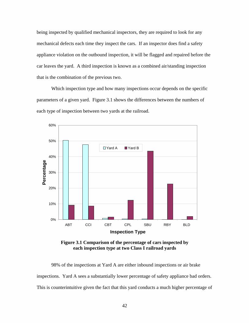
42
being inspected by qualified mechanical inspectors, they are required to look for any
mechanical defects each time they inspect the cars. If an inspector does find a safety
appliance violation on the outbound inspection, it will be flagged and repaired before the
car leaves the yard. A third inspection is known as a combined air/standing inspection
that is the combination of the previous two.
Which inspection type and how many inspections occur depends on the specific
parameters of a given yard. Figure 3.1 shows the differences between the numbers of
each type of inspection between two yards at the railroad.
0%
10%
20%
30%
40%
50%
60%
ABT CCI CBT CPL SBU RBY BLD
Inspection Type
Perc
enta
ge
Yard A Yard B
Figure 3.1 Comparison of the percentage of cars inspected by
each inspection type at two Class I railroad yards
98% of the inspections at Yard A are either inbound inspections or air brake
inspections. Yard A sees a substantially lower percentage of safety appliance bad orders.
This is counterintuitive given the fact that this yard conducts a much higher percentage of

43
standing inspections compared to Yard B. The distribution of inspection types at Yard B
is more uniform, with the majority being Roll-By or End-of-Train Device inspections.
Additionally, railroads monitor a large number of parameters associated with the
inspection or railcars. Table 3.2 contains data pertaining to the inspection of cars at Yard
A. As can be seen in the data, the bad order percentage is the highest for standing
inspections.
Shift Inspection Type
Total Number of Trains
Total Number of Cars/
Inspection
Average Number of Cars/Train
Average Dwell Time
(Min)
Avg Inspection Time (Min)
Average Wait Time
(Min)
Average Minutes / Car
(Planned)
Average Minutes /
Car (Actual)
Number of B/Os B/O %
ABT 482 29,586 61 27.7 16.1 11.6 2 1.9 86 0.3CBT 5 128 26 12.0 4.0 8.0 4 4.0 0 0.0CCI 423 21,652 51 35.7 16.9 18.8 2 1.9 391 1.8CPL 1 44 44 0.0 0.0 0.0 1 1.0 1 2.3SBU 233 233 1 26.3 2.0 24.3 18 17.4 0 0.0ABT 364 23,714 65 29.3 15.7 13.6 2 2.0 37 0.2CBT 14 1,001 72 78.2 19.3 58.9 4 1.9 3 0.3CCI 562 28,022 50 22.7 9.9 12.8 2 2.0 289 1.0CPL 2 154 77 0.0 0.0 0.0 1 1.0 0 0.0SBU 117 117 1 31.8 2.5 29.3 18 16.4 0 0.0ABT 447 26,783 60 27.2 17.5 9.6 2 2.0 49 0.2CBT 9 358 40 0.0 0.0 0.0 4 3.7 2 0.6CCI 484 26,134 54 27.1 16.4 10.7 2 1.9 369 1.4CPL 9 642 71 17.8 7.8 10.0 1 0.9 3 0.5SBU 297 297 1 26.8 2.0 24.8 18 16.9 0 0.0
TOTAL 3,451 158,985 46.0 27.9 12.7 15.2 2.1 2.0 1,189 0.8
Second
First
Third
Table 3.2 Data from one Class I railroad yard representing parameters that
are monitored with respect to the car inspection process
3.10 Safety Appliance Use
Currently, each railroad has its own procedures regarding use of safety
appliances. Some railroads allow their employees to mount and dismount a railcar while
it is moving provided they follow specific procedures dictating how to do so safely.
Other railroads allow their employees to ride on safety appliances while the car is in
motion, but do not allow the employees to mount it while it is moving. Each time a car is
to be mounted or dismounted it must be stopped and then restarted after the employee is
on or off board. The most conservative case would be railroads that do not allow
employees to ride on cars, of which the author knows no example.

44
3.11 Bad Order Options
If a safety violation exists on a car, it can be bad ordered to one of two locations.
If the damage is severe and the car cannot be repaired at its current location, the carman
will mark it to be sent to the nearest shop. If the car has less-serious defects, it can be
repaired on an Expedite Track. The AAR Interchange Rules (2004) define an expedite
track as a repair location not meeting the definition of a repair track (that is, mobile repair
vehicles and tracks performing repairs not requiring full repair equipment). The AAR
defines a repair shop (facility) / repair track as a location properly equipped, primarily
and regularly used for repair of freight cars which must be done in compliance with FRA
Railroad Freight Car Safety Standards, Safety Appliance and Power Brake Laws, and
AAR Interchange Rules.
An expedite track can be a physical track designation, but can also be a mobile
repair vehicle. A repair made on an expedite track does not require the air brakes to be
tested on a car regardless of when the car’s air brakes were last tested. However, air
brakes are required to be tested on a car the first time they are sent to a repair track or
facility in a given 12-month period. Thus sending a car to an expedite track versus a
repair track saves time and increases car utilization. The location where a defective car is
to be sent is noted on the bad order card for that car (Figure 3.2).
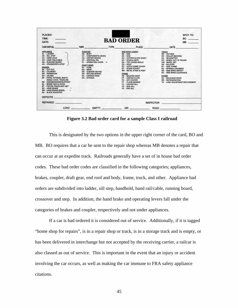
45
Figure 3.2 Bad order card for a sample Class I railroad
This is designated by the two options in the upper right corner of the card, BO and
MB. BO requires that a car be sent to the repair shop whereas MB denotes a repair that
can occur at an expedite track. Railroads generally have a set of in house bad order
codes. These bad order codes are classified in the following categories; appliances,
brakes, coupler, draft gear, end roof and body, frame, truck, and other. Appliance bad
orders are subdivided into ladder, sill step, handhold, hand rail/cable, running board,
crossover and step. In addition, the hand brake and operating levers fall under the
categories of brakes and coupler, respectively and not under appliances.
If a car is bad ordered it is considered out of service. Additionally, if it is tagged
“home shop for repairs”, is in a repair shop or track, is in a storage track and is empty, or
has been delivered in interchange but not accepted by the receiving carrier, a railcar is
also classed as out of service. This is important in the event that an injury or accident
involving the car occurs, as well as making the car immune to FRA safety appliance
citations.
46
Safety appliance bad orders can be avoided if the car is repairable in the yard
using a graduated pry-bar or other applicable tool to perform a “yard repair”. These
repairs are not generally tracked and increase car utilization because the car is not
removed from service while the repair is made.
There are no requirements for tagging safety appliance defects (FRA 2004a) and
the author is unsure why this is the case. It would seem that the FRA would need to
distinguish between cars with known defects being hauled to the nearest repair location
and those with defects that have not yet been identified. These two cases result in
substantially different responses from the FRA. It also seems that cars should be tagged
to warn unsuspecting employees of a car that has safety appliance defects.
3.12 Current Railroad Car Inspection Process
The current inspection process relies primarily on human vision to accomplish the
task of identifying railcars with defective safety appliances. Car inspectors are tasked
with identifying not only safety appliance defects, but a number of other mechanical
defects as well. Carmen inspect trains by walking or riding a vehicle alongside the train.
There are a variety of approaches to inspecting trains for safety appliance defects. Three
different examples for flat-switched yards are depicted in Figure 3.3.

47
4 Carmen
100-Car Train
25 Cars
Yard A
100-Car Train
Given:
2 Carmen Yard B
25 Cars 25 Cars 25 Cars
100-Car Train
2 Carmen Yard C
Outbound Inspection
Inbound Inspection
Inbound Inspection
4 Carmen
100-Car Train
25 Cars
Yard A
100-Car Train
Given:
2 Carmen Yard B
25 Cars 25 Cars 25 Cars
100-Car Train
2 Carmen Yard C
Outbound Inspection
Inbound Inspection
Inbound Inspection
Figure 3.3 Three different approaches to inspection at three Class I rail yards
Yard A is the highest volume yard of the three, inspecting about 2,800 cars per
day and uses four carmen to inspect trains. Each train is broken up into four blocks, and
the carman laces his or her cars before crossing over and inspecting the opposite side of
their portion of the train.
Yard B is a smaller yard, inspecting about 800 cars per day on inbound trains by
using two carmen per train. The two carmen start at the same end of the train and walk in
parallel on opposite sides of the train, allowing for communication between the carmen as
they walk along the train.
Yard C also uses two carmen to inspect trains, but they start at opposite ends of
the train. This yard is performing 1,000-mile brake inspections so the trains remain intact

48
and depart following inspection and other activities. It operates similarly to a stub-end
yard, with a large number of trains entering and leaving from the same end. As many as
3,600 cars may pass through each day, considerably more than either Yard A or B. As a
train enters the yard, one of the two carmen is awaiting its arrival at the entry end of the
yard and performs a roll-by inspection of one side of the train while the other awaits at
the end of the arrival track. Once the train is stopped and the track is blue flagged, the
carman begin their inspections traveling in opposite directions from either end. After the
inspections are complete the two carmen communicate with one another confirming that
they have finished their inspection. The carmen that was previously at the stub end of the
yard is now at the front of the departing train and gives a roll-by inspection to the second
side of the train as the train departs.
All three methods use the same number of person-hours, but result in different
turnaround times. The amount of traffic dictates how many inspectors are on hand at a
given yard and may also dictate whether or not the cars are inspected on the inbound or
the outbound. Yard A inspects cars on the outbound, whereas Yards B and C inspect cars
on the inbound. The differences in inspection time between Yards B and C come in
differing times needed to stage carmen to perform the roll-by inspections and also the
type of inspections being completed. Class IA brake inspections are being performed at
Yard C whereas pre-departure inspections are being performed at Yard B.
3.13 Train Inspections and Yard Efficiency
Inbound inspections are a critical part of the car handling process. Generally, as a
train enters a yard it is spotted on a receiving track where the locomotives and the EOT
device are detached. Next, the cut of cars (which is no longer a train due to the EOT

49
device being removed) is inspected before an engine takes it to the hump or switching
lead. In other words, the barrier between having a string of cars ready to hump and a
string of cars that cannot be removed from the receiving tracks is the inbound car
inspection. Once again, on the outbound, before a train can depart from a yard and after
the EOT device is attached, a Class I brake test must be performed per FRA regulations.
Both of the inspection tasks tie up capacity at receiving and departure tracks respectively
One benefit to increasing the efficiency of inspections would be the increased
virtual capacity to the receiving and departure tracks. If train inspections are expedited
through automated means, trains may be able to clear arrival and departure tracks in less
time. This method of increasing capacity could be beneficial in yards that are at or near
capacity and in need of additional track but are currently constrained from doing so for
various reasons. The resulting increases in throughput would result in lower train delay
costs and an overall increase in yard fluidity as well as provide for greater utilization of
tracks thus lessening the need for additional track design (Dirnberger 2006).
50
CHAPTER 4: RAILROAD SAFETY APPLIANCE STANDARDS, CFR PART 231
The Code of Federal Regulations Title 49 Part 231 is known as the Railroad
Safety Appliance Standards (FRA 2004b). The Railroad Safety Appliance Standards
apply to all standard gauge railroads with a few exceptions. These exceptions are mostly
railcars that operate completely within a facility and are not in interchange service. In
addition, rapid transit systems that are not connected with the general railroad system are
not covered in under 49 CFR Part 231. Four-wheeled coal cars and logging cars of eight
wheels are not covered under the Railroad Safety Appliance Standards if the center of
coupling is not more than twenty inches above the top of rail. Finally, except for
uncoupling device provisions, Part 231 does not apply to Tier II passenger equipment,
which operates at speeds exceeding 125 miles per hour.
Each car type is described within its respective section of the Railroad Safety
Appliance Standards. For the purpose of this thesis, the specifications for box and other
house cars built or placed in service before October 1, 1966, section §231.1 in Part 231,
are discussed. All cars are similar in terms of safety appliance requirements, and the
regulations for many other cars types reference the section on box and other house cars
without roof hatches, making this type a good candidate for explanatory purposes. The
following example does not cover each parameter listed in Part 231, but the critical ones
for open-top hoppers and gondolas with high sides are noted and explained. In addition
to the respective sections for cars, there is a section pertaining to drawbar heights.
51
Drawbar heights for all cars are covered in §231.31 and the center of drawbar should be
between 31.5 and 34.5 inches above the top of rail.
4.1 Handbrakes
One vertical wheel handbrake, which can be of any
efficient design, is required for each car with the total braking
force no less than that pressure that is applied to the brake shoes
when the brake cylinder is at fifty-pounds per square inch. The
brake wheel may be deep or shallow and constructed of malleable
iron, wrought iron, steel, or equivalent material with a nominal
diameter of twenty-two inches. The depth of the brake wheel hub
shall be two and five-eighths inches with a square taper shaft fit,
tapering two inches in twelve inches with a small end of the taper
fit seven-eighths inches. When wound in a counterclockwise
direction, the brake wheel can have no means of preventing
applications. The brake shaft shall be not less than seven-eighths
of an inch square with a square fit taper. All handbrake chains
should be no less than nine-sixteenth inch BBB chain and
handbrake rods shall be no less than three-fourths inch diameter.
The handbrake shall be located between seventeen and twenty-two
inches from the center of car so that it can be operated from the
horizontal end platform while the car is in motion. Handbrakes
should not be between twenty-six and forty inches from the top of
end-platform tread. Brake wheels should be held in place by a nut

52
on threaded shaft (of three-fourths inch) and the nut should be
secured by riveting over or by the use of a locknut of suitable
cotter. The outside edge of the brake wheel should not be less than
four inches from a vertical plane which passes through the inside
face of knuckle when closed with the coupler horn against the
buffer block. The handbrake housing should be securely fastened
to the car.
4.2 End Platforms
Two end platforms shall be provided with a width no less
than eight inches and length no less than sixty inches. One
platform should be centered on each end of a car between inner
ends of handholds no more than eight inches above the top of
center sill. Three metal braces should support the end platforms
with a minimum cross sectional area of three-eighths by one-half
inches secured using one-half inch bolts or rivets. Depending on
whether the longitudinal travel in the draft gear is greater than or
less than twelve inches, the platform should be located no less than
six or no less than twelve inches from the inside face of knuckle
when closed with the coupler horn against the buffer block. The
platform can be made of wood or other material with the same or
greater degree of safety, and should be constructed to allow for the
elimination of snow and ice.

53
4.3 Sill Steps
Four sill steps with a minimum cross sectional area of one-
half by one and one-half inches made of wrought iron, steel, or
other material of equivalent strength should be located on cars,
with a ten (preferably twelve) inch tread and eight inch clear depth.
One shall be located near each end of the car with no more than
eighteen inches between the center of sill step and end of car. The
outside face of the step should be no more than four inches inside
of the face of car, preferably flush with the car. The tread should
be no more than twenty-four (preferably twenty-two) inches from
the top of rail. Any sill step exceeding twenty-one inches in depth
shall have an additional tread, and all sill steps shall be fastened
with one-half inch bolts with nuts on the outside and one-half inch
rivets.
4.4 End Ladder clearance
No part of the car other than the buffer block, brake shaft,
brake wheel, end platform, horizontal end handholds, or
uncoupling lever that is within thirty inches of side of car shall
extend to within twelve inches of a vertical plane parallel with the
inside face of knuckle when closed with the coupler horn against
the buffer block at full buff. Other than the ones noted, no part of
the car shall extend beyond the outer face of the buffer block.

54
4.5 Side Handholds
Sixteen side handholds with a minimum diameter of five-
eights inches made of wrought iron, steel, or other material of
equivalent strength should be located on cars, with a twelve
(preferably twenty-four) inch minimum clear length and two
(preferably two and one-half) inch clearance. Four should be
located on each end of the car located no more than nineteen
inches apart with the bottom handhold no more than twenty-one
inches above the top tread of the sill step. The top handhold
should coincide with the top end handhold, within a 2” variance.
Spacing of side handholds should be within two inches of bottom
handholds with a clearance of the outer end of the handholds being
no more than eight inches from the end of the car. The side
handholds should be securely fastened with no less than one-half
inch bolts with nuts on outside and riveted with no less than one-
half inch rivets. Bottom handholds should have a foot guard or
some type of upward protection no less than two inches in height
near the inside end.
4.6 End Handholds
Sixteen end handholds with a minimum diameter of five-
eights inches made of wrought iron, steel, or other material of
equivalent strength should be located on cars, with a sixteen
(preferably twenty-four) inch minimum clear length and two
55
(preferably two and one-half) inch clearance. For horizontal
handholds, four should be located near each side and on each end
spaced no more than nineteen inches apart. The bottom handhold
should be no more than twenty-one inches from the top tread of sill
step with top handhold coinciding in height (within two inches)
with the end platform handholds. The end handholds should be
securely fastened with no less than one-half inch bolts with nuts on
outside and riveted with no less than one-half inch rivets. End
handholds should have a foot guard or some type of upward
protection no less than two inches in height near the inside end.
4.7 Horizontal End-Platform Handholds
Two horizontal end-platform handholds with a minimum
diameter of five-eights inches made of wrought iron, steel, or other
material of equivalent strength should be located on cars, with a
sixty-inch minimum clear length and a two (preferably two and
one-half) inch clearance. One should be located on each car
between forty-eight and sixty inches above end platforms no more
than six inches from the inner legs of top end handholds. The
horizontal-end platform handholds should be securely fastened
with no less than one-half inch bolts with nuts on outside and
riveted with no less than one-half inch rivets.
56
4.8 Uncoupling Levers
Handles not conforming to Plate B should be no more than
six inches from the side of car with one on each end of the car.
Plate B handles should be no more than twelve (preferably nine)
inches from the side of cars and have a center lift arm of no more
than seven inches. In addition, Plate B handles should have a
center of lift arm of no more than three and one-half inches beyond
the center of the coupler. Handles should extend no less than four
inches below the bottom of the sill step with two inches of
clearance around handle. The minimum drop of handles is twelve
inches, or fifteen inches overall. All handles of uncoupling levers
of the “rocking” or “pushdown” type shall be no less than eighteen
inches from the top of rail when the lockblock has released the
knuckle. A stop shall be provided to ensure that the inside arm
does not fly up in the event of a breakage. One handle shall be
placed on the left side of each end of the car.

57
CHAPTER 5: SAFETY APPLIANCE INSPECTION COST MODEL
5.1 Introduction to the Industrial Inspection Process
Inspection, in manufacturing applications, is defined as the process of determining
the conformance of a product to a given set of requirements (Cielo 1998). In a
manufacturing environment, a product may be inspected at various points during the
manufacturing process to ensure quality conformance, but once the product is constructed
and exits the manufacturing process, the inspections cease. Unlike the industrial
inspection process, railcar safety appliances are repeatedly inspected over the lifetime of
the railcar. Despite this difference, there are some correlations between the
manufacturing inspection process and the method railroads use for mechanical car
inspections, including safety appliance inspections.
Safety appliances receive an inspection that is analogous to the industrial quality
conformance inspection, but this occurs only during construction and possibly
immediately after the construction process. Additionally, when a railcar design is
generated by a car manufacturer the FRA must approve the safety appliance design
through a “sample-car inspection” that ensures the appliances are compliant before the
car type is placed in service (FRA 2004a).
The number of defect types encountered in typical industrial inspection processes
is likely to be less than the number encountered in the railroad car inspection process. In
the industrial inspection process, there are typically a limited number of defect types to
be expected as the product passes down the assembly line due to the relatively controlled
environment. This is not the case for railcar safety appliances as there are a multitude of
58
damage types that occur during its operation. Each safety appliance has many parameters
that must be in compliance with the possibility that each is in violation in a variety of
ways. For instance, the 2” clearance of a ladder rung could be in violation at any point
along the rung, creating a myriad of possible instances of deformation resulting in an
FRA defect. While these different forms of deformation may not be difficult for human
vision to detect, their detection is nontrivial when it comes to writing computer
algorithms capable of detecting all the possible forms of deformation that could cause a
car to be non-compliant.
Inspections can be carried out by human or automated means, or as a combination
of the two. The current process calls for railcars to be repeatedly inspected to ensure
their mechanical components are functional. The repetition of railroad car inspections
stems from the large number of components that must be inspected on a railcar, and the
short amount of time available to inspect them during typical inspections.
The manufacturing industry is well suited for automated inspection due to the
uniformity in parts that travel down a given assembly line. This is because, in a
manufacturing plant, there is a production line producing a constant stream of identical
goods. The railroad inspection process is similar as there is still an assembly line (yard
lead or any track) that the product (railcars) traverses when leaving or entering a yard.
However, in many North American rail yards, the types of railcars passing through and
requiring inspection vary enormously. There are 1.3 million railcars of hundreds of types
and varieties in operation in North American (AAR 2003b). Inspection systems, whether
human or mechanized, must be able to accommodate any and all of them. Conversely,
there are some locations in North America that have only a very limited number of car

59
types. For example, rail cars operating in the Powder River Basin of Wyoming and
Montana are highly uniform. Inspectors working in these locations may see hundreds of
railcars of a specific type in a given shift. At other yards, the distribution of car types is
more uniform and inspectors are faced with multiple car types within a shift and even
within a given train. It is unknown what affect, if any, these differences have on the
effectiveness and efficiency of inspections.
5.2 Types of Industrial Inspection Processes
In the manufacturing industry there are several types of inspection processes;
batch, patrol, and continuous inspections (Cielo 1998). Batch inspections involve the
inspection of a small percentage of goods after the production process. Determining
batch size involves statistical analysis based on the percentage of defective parts that are
considered acceptable for the particular process. Patrol inspections involve a control
officer making rounds during the inspection process searching for defects that are readily
visible on some, but not necessarily all, of the parts produced.
Railcar inspections do not fall into either of these inspection types but instead are
the third and strictest type, continuous inspection. In a continuous inspection process,
one hundred percent of objects (railcars) are inspected prior to being released (departing).
The need for “continuous” inspection of railcars stems from the criticality of complying
with safety standards and the large number of components that must be inspected.
5.3 Relationship Between Inspection Rate and Defect Detection
Carmen often inspect hundreds of cars per day, sometimes as many as 1,100 –
1,200 cars per shift. Such a large number of inspection units may lead to missed defects

60
for several reasons related to human capabilities. One hundred percent conformance
refers to one hundred percent of the actual defects being identified and is not realistically
produced even with 100% inspections. In manufacturing, 98% conformance is
considered good and levels as low as 80% are often found (Cielo 1998).
The acceptable level varies depending on the relative cost of detecting defects
relative to the cost of allowing the defects to persist or changing the manufacturing
process to prevent them. In this sense it is an optimization problem and each such
process will have a different optimum depending on the relative functional relationships
of these parameters. The optimization of the railcar inspection process will be discussed
in Section 5.4, Qualitative Inspection Cost Model. One obstacle to humans’ ability to
achieve 100% inspection is the inherent monotony of many inspection tasks. Certain
inspector characteristics increase the accuracy of inspections such as conscientiousness,
patience, ability to thwart fatigue, aptitude, and a rhythm for inspecting (Kennedy and
Andrews 1977, Cielo 1998).
The functional relationship between the number of defects escaping inspection
and inspection rate is not as simple as intuition might suggest. Audited studies of
inspection effectiveness indicate a more complex relationship (Kennedy and Andrews
1977). A typical inspector completing 100% inspections at differing inspection speeds
shows the effect of inspection rate on percent conformance (Figure 5.1).

61
Per
cent
of D
efec
ts E
scap
ing
Insp
ectio
n
A B Number of Pieces Inspected Per Hour
Per
cent
of D
efec
ts E
scap
ing
Insp
ectio
n
A B Number of Pieces Inspected Per Hour
Figure 5.1 Functional relationship between percent of defects escaping detection and
inspection rate of a human inspecting using 100% inspection (Kennedy and Andrews 1977)
When inspection rate is low, the number of missed defects is also low (Figure
5.1). As inspection rate increases, so does the percentage of defects that are missed until
a local maximum is reached at point A. As the inspection rate continues to increase after
point A, the percentage of defects escaping detection actually decreases due to reduction
in monotony until it reaches a minimum at point B. Beyond point B, the percentage of
defects missed increases once again as fatigue and the limits of human cognitive ability
begin to have a greater effect and the percent conformance decreases.
Applying this model to railcar inspection should be done with some caution
however. The functional relationship described in Figure 5.1 applies to inspections of
like pieces inspected under consistent conditions. This is not necessarily the case with
railroad safety appliance inspections. It is also important to consider the varying levels of
difficulty of inspecting different safety appliances using current methods. For instance, a
62
handhold that violates the 2” clearance rule may be more easily detected than a brake
wheel that violates the 4” clearance rule. Beyond this, different parameters for the same
safety appliance have varying levels of difficulty in identification depending on the
location of the appliance. If a rung on a ladder is damaged at eye level, it may be easily
detected, but if the top ladder rung on a car is damaged, it may be difficult to detect.
Based on field visits with carmen at several Class I rail yards, it is evident that
individual carman have different aspects of the railcar that they are more attuned to. At
one yard a carman identified his fellow carmen by what aspects of the car they were
known for detecting defects on. In theory, the variation in types of defects found by
carmen adds to the effectiveness of the current inspection process. This is assuming that
each carman is capable of detecting many types of defects, but is specialized in detecting
one type of defect. This, coupled with the fact that cars are randomly assigned to carmen
means one carman does not repeatedly see any one car. Over time, cars pass by a variety
of inspectors, each with the ability to scrutinize one aspect of the car better than the last
inspector. However, such a system is haphazard at best, and does not address those
defects that are uniformly difficult to detect.
5.4 Qualitative Inspection Cost Model
There are costs associated with any inspection process, including railcars. These
can be broken down into three categories; failure costs, improvement costs, and total
inspection costs (Cielo 1998). Analyzing these three inspection costs is known as quality
cost analysis and allows one to determine the optimal amount that should be spent on
quality conformance (Feigenbaum 1983). In this section I adapt a general manufacturing
inspection cost model developed by Cielo (1998) to the railroad car inspection process

63
and then explore how new applications of enhanced railcar inspection technology might
affect that model.
5.4.1 Failure Costs
Costs of failures in railcar inspections come in several forms; FRA fines, delay
cost of setting out damaged or defective cars if they are discovered once they are in an
outbound train, the risk of a train accident caused by a defective car, or of injury or death
to employees due to missed defects. FRA fines are not levied on all non-compliant safety
appliances but when they are, they range from $500 to $7,500 per violation (FRA 2004b).
Each day that a safety appliance violation occurs constitutes a separate violation (FRA
2004b). The costs of injury or death are the costs of litigation due to an incident
involving defective safety appliances. The cost due to train delay results from setting out
a car prior to departure after a safety appliance violation was found on an outbound
inspection that should have been found on the inbound inspection. The resulting costs
apply to the cumulative delay for all of the cars and locomotives on the train, as well as
the costs of the crew.
Additionally, other trains may be delayed as a result of the defective car being set
out by the original train. Train delays can significantly impact the fluidity of the overall
network. Furthermore, if the car had been noticed on the inbound it could have been
under repair during the time it spent in the yard thereby improving asset utilization.
5.4.2 Improvement Costs
Improvement costs will generally increase with conformance percentage. There
are three typical approaches to increasing conformance percentages for safety appliances:
64
1) reduce the rate (speed) of inspection, 2) increase the aptitude of inspectors through
better training, or 3) incorporating some type of technology to enhance inspectors’ ability
to perform their task. Slowing the rate of inspection will reduce productivity and will
require either more carmen, or longer hours for the same number of carmen. In either
case, slowing the rate of inspection will lead to higher labor cost. Providing carmen with
additional or improved training and guidance may also prove useful in raising the
conformance percentage. This has been the principal approach used by the railroad
industry and it is beneficial; however, due to limitations in human physical, sensory, and
cognitive capabilities there will ultimately be diminishing returns to this approach.
Costs associated with improving inspections become incrementally larger as
100% conformance is approached (Figure 5.2). One hundred percent conformance is only
hypothetical, as the improvement cost curve (Figure 5.2) never reaches the point of
complete conformance (Cielo 1998). As a carman inspects a train, the most obvious
defects are those that would be flagged first, with the more difficult ones being detected
at a decreasing rate relative to the effort expended. Thus, as more time is spent
inspecting a given train, more defects will be located. Each additional incremental
amount of time and effort detecting defects should return more defects, but will do so at a
decreasing rate. For example, as previously explained, FRA inspectors spend more
inspection time per car than railroad carmen, thus their rate of conformance should be
higher.
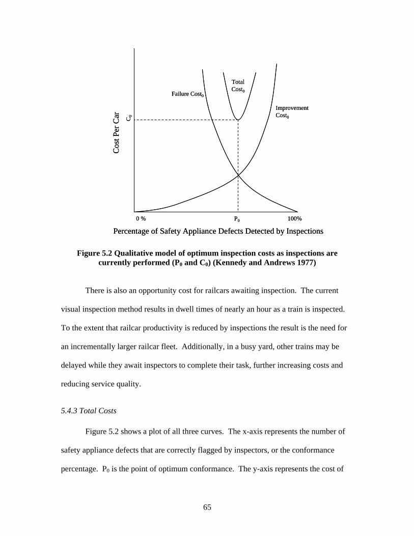
65
Percentage of Safety Appliance Defects Detected by Inspections0 % 100%
Cos
t Per
Car
Failure Cost0
TotalCost0
P0
C0
ImprovementCost0
Percentage of Safety Appliance Defects Detected by Inspections0 % 100%
Cos
t Per
Car
Failure Cost0
TotalCost0
P0
C0
ImprovementCost0
Figure 5.2 Qualitative model of optimum inspection costs as inspections are currently performed (P0 and C0) (Kennedy and Andrews 1977)
There is also an opportunity cost for railcars awaiting inspection. The current
visual inspection method results in dwell times of nearly an hour as a train is inspected.
To the extent that railcar productivity is reduced by inspections the result is the need for
an incrementally larger railcar fleet. Additionally, in a busy yard, other trains may be
delayed while they await inspectors to complete their task, further increasing costs and
reducing service quality.
5.4.3 Total Costs
Figure 5.2 shows a plot of all three curves. The x-axis represents the number of
safety appliance defects that are correctly flagged by inspectors, or the conformance
percentage. P0 is the point of optimum conformance. The y-axis represents the cost of

66
inspection per car. The optimum cost of inspection occurs at C0, where the total cost
curve is at a minimum. The total cost curve is the summation of the improvement and
failure cost curves. The point of minimum cost (C0) is also the point where the
inspection effort is minimized. This cost can be directly equated to an amount of time
that should be spent to inspect a railcar if the objective is to maximize the economic
efficiency of railcar health and inspection costs.
5.5 Qualitative Inspection Cost Model after the Addition of New Technologies to the Inspection Process
Improvements in the railcar inspection process would shift the total cost curve
(Figure 5.2). These improvements could be as simple as changes in inspection
methodology or additional tools for the carmen or involve use of sophisticated
technology such as use of machine vision for railcar inspection. Such enhancements will
not generally affect the failure cost curve for car inspections; however, the improvement
cost curve would be affected (Figure 5.3) because of the lower unit inspection cost for
inspections. The benefits of using additional technologies such as machine vision to
monitor railcar safety appliances are twofold; 1) it will reduce the cost of inspection and
2) fewer defects will pass through the inspection, resulting in a higher conformance
percentage. A reduction in costs (C0 C1) would occur if the operating costs of a
machine vision system were less than the current system. An increase in conformance
percentage (P0 P1) would occur as a result of machine vision systems being objective
and providing more reliable results. The result is a system that is both more effective and
efficient, and thereby safer and more economical.

67
Percentage of Safety Appliance Defects Detected by Inspections
0 % 100%
Cos
t Per
Car
ImprovementCost1
Failure Cost
TotalCost0
P0
C0
C1
P1
TotalCost1
ImprovementCost0
Percentage of Safety Appliance Defects Detected by Inspections
0 % 100%
Cos
t Per
Car
ImprovementCost1
Failure Cost
TotalCost0
P0
C0
C1
P1
TotalCost1
ImprovementCost0
Figure 5.3 Qualitative model of optimum inspection costs after the addition of additional technology to safety appliance inspections (P1 and C1)
(adapted from Kennedy and Andrews 1977)

68
CHAPTER 6: METHODS OF IMPROVING THE EFFICIENCY AND EFFECTIVENESS OF RAILROAD SAFETY APPLIANCE INSPECTIONS
One means by which the efficiency and effectiveness of car inspections can be
increased is through the use of technology. There are multiple technologies that are
currently being employed to aid in the inspection of mechanical components of railcars.
An example of wayside rail vehicle health monitoring system that includes a memory
capability is the Wheel Impact Load Detector (WILD). WILDs detect vertical loads at
wayside installations and report the information to a central system that monitors rail
vehicles’ performance (Morgan and Anderson 2003, Luzcak 2005). Another wayside
vehicle monitoring system is the Truck Performance Detector (TPD) that detects poorly
performing trucks by monitoring lateral loads. The Transportation Technology Center
Inc. (TTCI) is also deploying a new visual inspection system known as FactIS to inspect
railcar truck components including wheels, brake shoes, and other mechanical
components.
6.1 Machine Vision Overview
Machine vision can be used for a number of railcar inspection tasks (Hart et al
2004, Lai et al 2005), including many aspects of safety appliance inspections. Machine
vision consists of capturing digital images and using algorithms to detect certain
attributes in these images. In the context of this work, these images are of railcar safety
appliances and the attributes are various forms of defects or deformation.

69
The terms computer vision and machine vision are generally associated with one
another. Generally, computer vision refers to the field in general and machine vision is
used when referring to industrial applications of the technology (Shapiro 2001).
The most common input devices for machine vision systems are charge-coupled
device (CCD) sensors (Shapiro 2001). CCD cameras work by converting light energy
from each cell into an electrical charge. The CCD camera plugs into a computer with a
frame grabber. The frame grabber is capable of storing the images and also controls the
camera. With new technologies such as FireWire, which provide a digital signal,
traditional analog frame grabbers are not necessary (Shapiro 2001, Hart 2006). Many
newly manufactured personal computers (PCs) are equipped with a FireWire port (Hart
2006).
Videos intended for human viewing are generally captured at a rate of 30 frames
per second (Shapiro 2001). Specifically, these frames are captured at a rate of 60 half-
frames per second, allowing the video to be perceived smoothly by humans. A frame rate
of 60 half-frames per second is unnecessary for machine vision purposes, and a rate of 30
frames-per-second works sufficiently for many applications unless the speed of the
inspection process dictates a higher rate.
6.2 Comparison of Human Vision and Machine Vision
Understanding the strengths and weaknesses of human and machine vision is
helpful in understanding the possibilities of machine vision. Humans are capable of
analyzing complex and dynamic situations. However, humans are not as good at
performing repetitive inspections without suffering from boredom and fatigue.
Additionally, for many tasks, humans are not as reliable at judging objects with the level
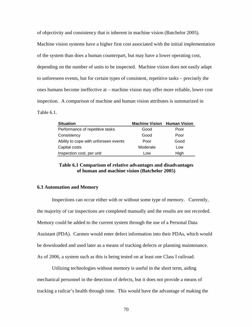
70
of objectivity and consistency that is inherent in machine vision (Batchelor 2005).
Machine vision systems have a higher first cost associated with the initial implementation
of the system than does a human counterpart, but may have a lower operating cost,
depending on the number of units to be inspected. Machine vision does not easily adapt
to unforeseen events, but for certain types of consistent, repetitive tasks – precisely the
ones humans become ineffective at – machine vision may offer more reliable, lower cost
inspection. A comparison of machine and human vision attributes is summarized in
Table 6.1.
Situation Machine Vision Human VisionPerformance of repetitive tasks Good PoorConsistency Good PoorAbility to cope with unforseen events Poor GoodCapital costs Moderate LowInspection cost, per unit Low High
Table 6.1 Comparison of relative advantages and disadvantages of human and machine vision (Batchelor 2005)
6.3 Automation and Memory
Inspections can occur either with or without some type of memory. Currently,
the majority of car inspections are completed manually and the results are not recorded.
Memory could be added to the current system through the use of a Personal Data
Assistant (PDA). Carmen would enter defect information into their PDAs, which would
be downloaded and used later as a means of tracking defects or planning maintenance.
As of 2006, a system such as this is being tested on at least one Class I railroad.
Utilizing technologies without memory is useful in the short term, aiding
mechanical personnel in the detection of defects, but it does not provide a means of
tracking a railcar’s health through time. This would have the advantage of making the

71
system less memory intensive from a data storage perspective. However, the addition of
memory to the inspection process could enhance the effectiveness and value of the
machine vision system by improving maintenance scheduling and efficiency. While all
FRA safety appliance defects must be repaired before a train can depart a yard, there are
other forms of deformation that could be repaired as time allows. For instance, if a ladder
is deformed, but not a FRA defect, it would likely be repaired in its next visit to a repair
facility. Memory in the inspection of railcars could lead to better scheduling of
upcoming maintenance on a railcar, and ensure the needed parts are in stock or on the
way before the car arrives at the facility. Examples of system memory could range from
storing digital images for image correlation purposes, or matching safety appliance data
with car numbers and storing this information in a database.

72
CHAPTER 7: MACHINE VISION SYSTEM FOR THE DETECTION OF SAFETY APPLIANCE DECECTS
In this chapter I describe the decisions involved with selecting the location and
viewing parameters of a machine vision inspection system for railcar safety appliances.
This includes both macro and micro level considerations ranging from the location on the
railroad network where inspection systems should be installed, to the specific camera
angle needed for collection of safety appliance images that are satisfactory for analysis of
the desired parameters. I also discuss the primary components of the machine vision
system capable of detecting defective railcar safety appliances. These components are
the image acquisition system, algorithms, and field setup for a machine vision system.
The location of a machine vision installation for monitoring safety appliances can
be broken down into three aspects. The first of these is the location of the inspection site
on the railroad network. Secondly, the view must be identified. The camera view is the
portion of the railcar that is captured within the image frame of view. Once the view is
set, the camera angles must be determined to ensure the needed safety appliance
parameters are captured.
7.1 Machine Vision System Locational Requirements
There are many factors involved in the decision of where a machine vision system
should be located with the goal of providing the greatest benefit to the railroad and
integrating the system with railroad operations. The use of the data that will be captured
by the installation should dictate the location of the installation. Data can be used for
FRA mandated inspections, preventative maintenance, planned maintenance, or some

73
combination of the three purposes. There are two general locations for a machine vision
system capable of detecting defective safety appliances; 1) at a location where trains are
funneling into a terminal and 2) on the road between terminals. Regardless of the use of
data, the detection system will need to be a sufficient distance outside of a terminal to
allow for the processing and transfer of information on defective safety appliances,
interpretation by the appropriate mechanical personnel at the yard, and decisions to be
made regarding how each car is to be handled when it arrives.
Data for FRA-required inspections should be captured early enough to allow
mechanical personnel to have information on defective cars in hand when an inbound
train arrives on a receiving track. There are additional issues that must be considered if
the data are to be used to perform FRA-required inspections. One question concerns
between-terminal locations and how mechanical defects are handled after they have been
identified. If a car has a safety appliance defect, current practice is to set it out at the
nearest location that a suitable repair can be made as required in the safety appliance
statute. If a mobile repair vehicle is assigned to the area, the nearest location where a
repair could be made would likely be closer than the next terminal. This would require
the train to be stopped and the car set out before reaching a terminal.
The issue of whether or not to stop a train for safety appliance defects detected by
a wayside machine vision installation should be resolved between the AAR, railroads,
and the FRA as machine vision inspection of railcars becomes more prevalent. The
development of new technology-driven inspection capabilities will raise issues that need
to be addressed, lest they stymie development and implementation of new more effective
and efficient technologies that can improve safety and railroad performance.
74
Data for preventative or planned maintenance could be gathered at either the
between-terminal or terminal entrance locations, depending on how much time the
mechanical department at the repair location needs to react to the information. Planned
and preventative maintenance will generally not apply to safety appliances because
defects tend to occur as a result of acute events rather than long term wear. By contrast,
use of wayside inspection systems is likely to be useful for detecting defects and wear on
mechanical components, such as brake shoes thereby improving inspection efficiency.
For example, mechanical personnel at an upcoming terminal will know the number and
type of brake shoes required for repair of cars in an inbound train before it arrives.
Once mechanical defects are detected on the railcar, this information must be
transmitted in a useful form to railroad personnel. All railcars in North America are
equipped with Automatic Equipment Identification (AEI) tags, which identify cars and
provide certain other basic information. Generally, wayside detection systems are
located in close proximity to AEI installations. In addition to the AEI encoded
information, the car number can be used to query the Uniform Machine Language
Equipment Register (UMLER) for additional car specific information if needed. This
will provide car type information that is needed to determine which part of CFR Part 231
the car is governed by. Safety appliance health may be tracked in some type of a
database, but the specifics of this database have not yet been developed. Some methods
of determining the health of safety appliances may circumvent the need to have a
database of safety appliance information, or reduce the data to a few binary fields
representing classes of defects.
75
7.2 Camera View
The goal in camera view selection is to capture the maximum number of safety
appliances with a minimum number of cameras. In addition, each camera view must be
evaluated in terms of how many safety appliance parameters can be identified from the
view. I considered the advantages and disadvantages of each camera view for the safety
appliances addressed in this phase of the project. In considering this section, knowledge
of CFR Part 231 is necessary, an overview of which can be found in Chapter 4. The
camera views that will be considered are; perpendicular side, perpendicular overhead,
angled from above, angled from the side, and angled from the side and upward from
below rail height.
7.2.1 Perpendicular Side View
Figure 7.1 shows the side view perpendicular to the tracks. This camera view has
been successfully used in another project imaging intermodal train loading configurations
(Lai et al 2005). In that project the camera was set a distance of approximately 35.5 feet
from the track center. The perpendicular angle provides a good view of brake wheel
clearance and vertical displacement of side ladder rungs. On the other hand, it is
impossible to detect any aspects of the end ladder from this angle and it is also not
possible to determine if there is adequate clearance between ladder rungs and the car
body. Finally, it is difficult to detect sill step deformation in plane with the side of the car
body (e.g. violating the rule of being more than 4” inside the face of the car). Only one
camera is required to analyze a train from the perpendicular side view.
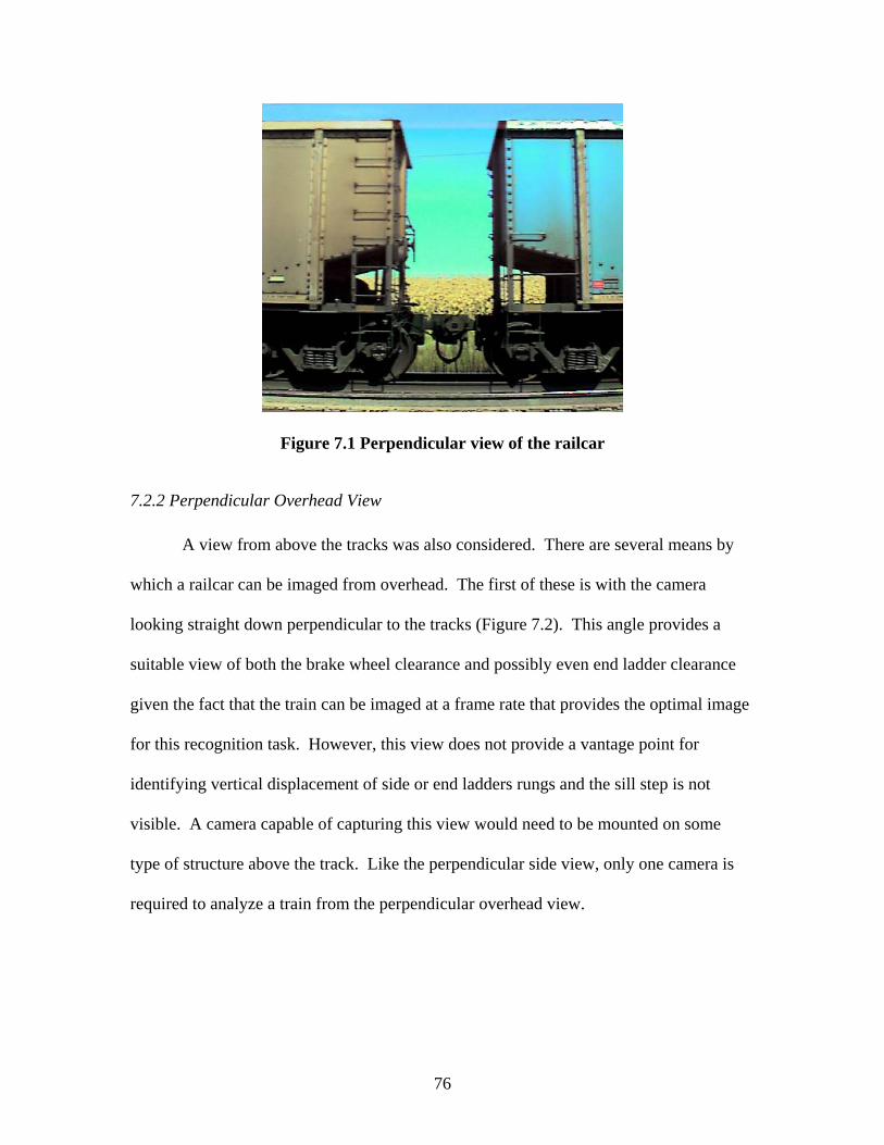
76
Figure 7.1 Perpendicular view of the railcar
7.2.2 Perpendicular Overhead View
A view from above the tracks was also considered. There are several means by
which a railcar can be imaged from overhead. The first of these is with the camera
looking straight down perpendicular to the tracks (Figure 7.2). This angle provides a
suitable view of both the brake wheel clearance and possibly even end ladder clearance
given the fact that the train can be imaged at a frame rate that provides the optimal image
for this recognition task. However, this view does not provide a vantage point for
identifying vertical displacement of side or end ladders rungs and the sill step is not
visible. A camera capable of capturing this view would need to be mounted on some
type of structure above the track. Like the perpendicular side view, only one camera is
required to analyze a train from the perpendicular overhead view.
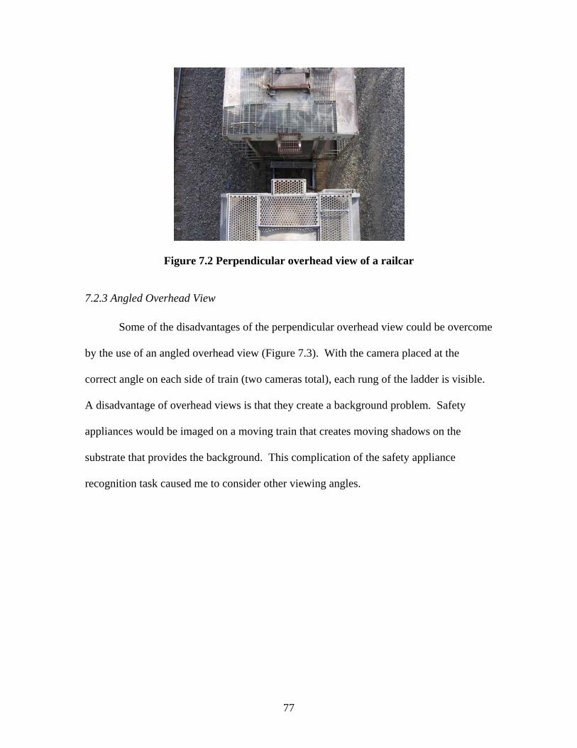
77
Figure 7.2 Perpendicular overhead view of a railcar
7.2.3 Angled Overhead View
Some of the disadvantages of the perpendicular overhead view could be overcome
by the use of an angled overhead view (Figure 7.3). With the camera placed at the
correct angle on each side of train (two cameras total), each rung of the ladder is visible.
A disadvantage of overhead views is that they create a background problem. Safety
appliances would be imaged on a moving train that creates moving shadows on the
substrate that provides the background. This complication of the safety appliance
recognition task caused me to consider other viewing angles.
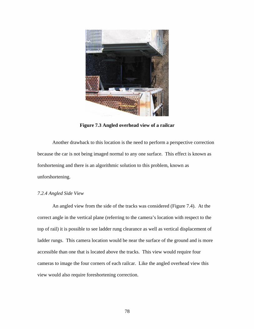
78
Figure 7.3 Angled overhead view of a railcar
Another drawback to this location is the need to perform a perspective correction
because the car is not being imaged normal to any one surface. This effect is known as
forshortening and there is an algorithmic solution to this problem, known as
unforshortening.
7.2.4 Angled Side View
An angled view from the side of the tracks was considered (Figure 7.4). At the
correct angle in the vertical plane (referring to the camera’s location with respect to the
top of rail) it is possible to see ladder rung clearance as well as vertical displacement of
ladder rungs. This camera location would be near the surface of the ground and is more
accessible than one that is located above the tracks. This view would require four
cameras to image the four corners of each railcar. Like the angled overhead view this
view would also require foreshortening correction.
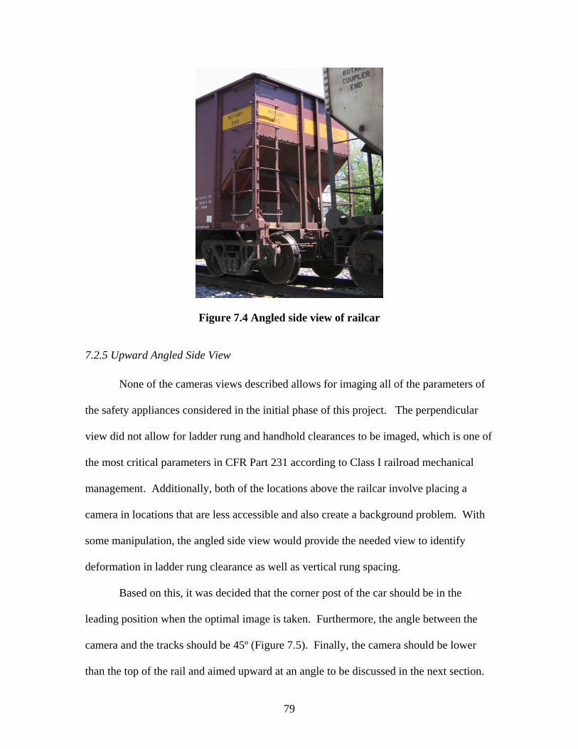
79
Figure 7.4 Angled side view of railcar
7.2.5 Upward Angled Side View
None of the cameras views described allows for imaging all of the parameters of
the safety appliances considered in the initial phase of this project. The perpendicular
view did not allow for ladder rung and handhold clearances to be imaged, which is one of
the most critical parameters in CFR Part 231 according to Class I railroad mechanical
management. Additionally, both of the locations above the railcar involve placing a
camera in locations that are less accessible and also create a background problem. With
some manipulation, the angled side view would provide the needed view to identify
deformation in ladder rung clearance as well as vertical rung spacing.
Based on this, it was decided that the corner post of the car should be in the
leading position when the optimal image is taken. Furthermore, the angle between the
camera and the tracks should be 45º (Figure 7.5). Finally, the camera should be lower
than the top of the rail and aimed upward at an angle to be discussed in the next section.

80
This view, after unforshortening takes place, allows for clearances as well as vertical
displacements in ladder rungs and handholds to be recognized using machine vision
algorithms. It is also possible to obtain images of both the sill step and uncoupling lever
from this view, although other views may be more effective for these recognition tasks.
Using this angle, four cameras would be required, one for each corner of the railcar.
Figure 7.5 Upward angled side view or railcar representing the optimal angle for viewing ladder, handholds, and the brake wheel
Table 7.1 summarizes each of the camera views that have been discussed in this
section. A check ( ) indicates that the safety appliance parameter listed in CFR Part 231
can be viewed and assessed from the given camera view.

81
Perpendicular Side
Overhead Perpendicular
Overhead Angled
Side Angled
Side Upward Angled
Vertical Displacement Spacing
Clearance
Vertical Displacement Spacing
Clearance
Vertical Displacement Spacing
Clearance
Vertical Displacement Spacing
Clearance
Brake Wheel Clearance Deformation
Number of Cameras Needed
1 1 2 4 4
End Ladder Rungs
End Handholds
Side Handholds
Camera ViewCFR Part 231 Parameter
Safety Appliance
Side Ladder Rungs
Table 7.1 Summary table of views considered in photographing safety appliances
7.3 Camera Angle
In order for ladder rung clearances to be visible from the camera, it was
determined that the camera should be located beneath the top of rail and aimed upward at
the railcar’s corner post. The camera is aimed toward the railcar at an angle of 45°
relative to the track (Figure 7.6). This allows the center post to be in the center of the
image, and ensures that the angles between the top chord and end post are equal on both
the side and the end of the railcar providing a symmetrical image.

82
B EndA End
Left Side
Right Side
Railcar
45º
B EndA End
Left Side
Right Side
Railcar
45º
Figure 7.6 Optimal camera angle relative to the track for the inspection of safety appliances using machine vision technology
Next, the camera’s location beneath the top of rail and resulting angle were
determined (Figure 7.7). This angle is approximately 6° and represents only the camera’s
physical location below the top of rail, and not the angle formed between the camera and
the camera target.
Top of Rail
6ºHorizontal
Top of Rail
6ºHorizontal
Figure 7.7 Angle representing the physical location of the camera beneath the top of rail

83
The locational parameters of the camera are given as angles instead of distances
whenever possible. This allows use of different focal length lenses. In other words, a
longer focal length camera would require the camera to be located farther from the track
center, but remains at an angle of 6° below the top of rail.
The other critical angle associated with the camera installation is the angle formed
between the center of the camera’s target and a horizontal line extending from the
camera’s sensor (Figure 7.8). The exact angle of the target and camera was determined
by obtaining images from many different camera angles and running the algorithm on the
images to determine which led to the best identification of representative defects. This
angle was determined to be approximately 55°. This places the center of the camera
target above the center of the railcar to compensate for higher car types than the ones that
are currently being evaluated. Additionally, this allows the top side and end ladder rungs
to be viewed with the underside of the railcar’s top chord as the background. If the rungs
were aligned with the edge of the top chord it would complicate the recognition task.
Top of Rail
6º55º
Horizontal
Top of Rail
6º55º
Horizontal
Figure 7.8 Critical angles in locating the camera for machine vision inspection of safety appliances
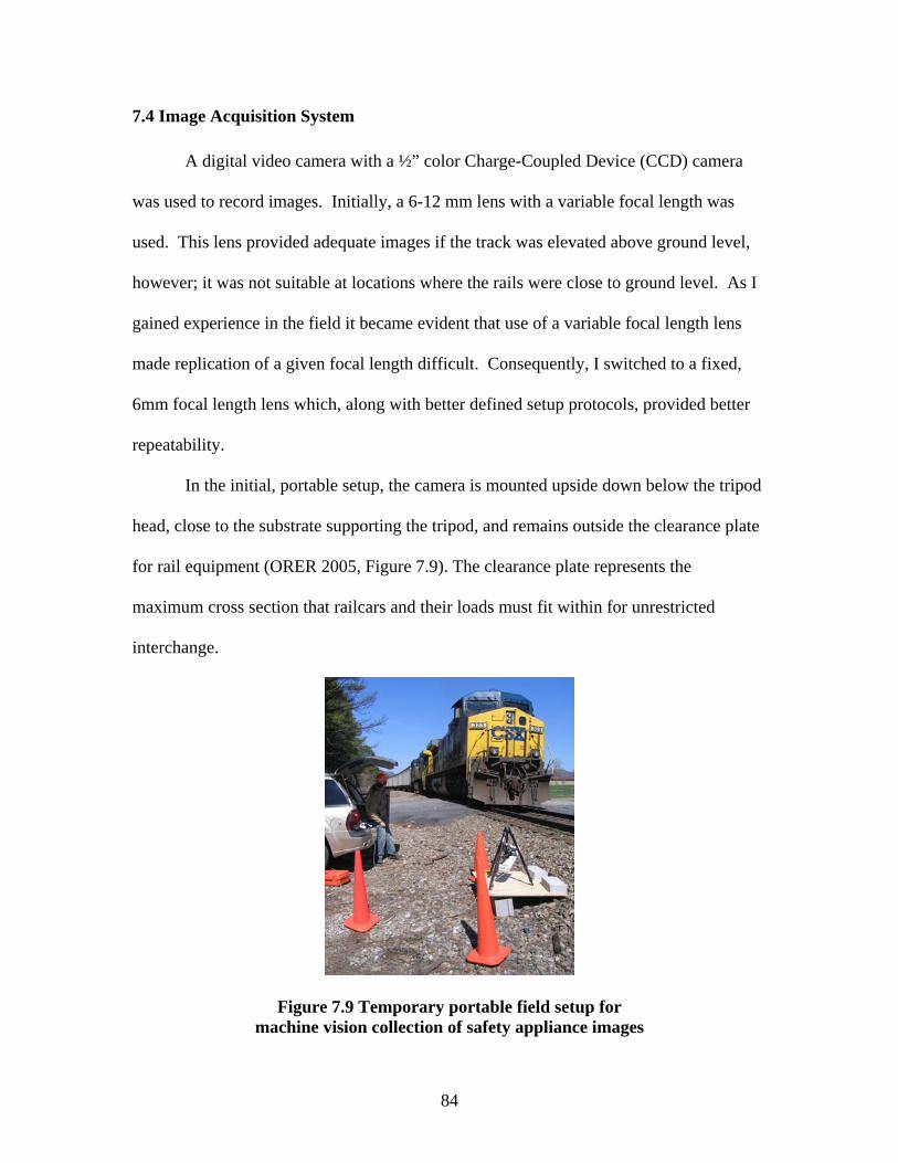
84
7.4 Image Acquisition System
A digital video camera with a ½” color Charge-Coupled Device (CCD) camera
was used to record images. Initially, a 6-12 mm lens with a variable focal length was
used. This lens provided adequate images if the track was elevated above ground level,
however; it was not suitable at locations where the rails were close to ground level. As I
gained experience in the field it became evident that use of a variable focal length lens
made replication of a given focal length difficult. Consequently, I switched to a fixed,
6mm focal length lens which, along with better defined setup protocols, provided better
repeatability.
In the initial, portable setup, the camera is mounted upside down below the tripod
head, close to the substrate supporting the tripod, and remains outside the clearance plate
for rail equipment (ORER 2005, Figure 7.9). The clearance plate represents the
maximum cross section that railcars and their loads must fit within for unrestricted
interchange.
Figure 7.9 Temporary portable field setup for machine vision collection of safety appliance images

85
Use of a resolution of 480x640 enabled the top ladder rung to be distinguished
without being considered noise. The noise threshold for this recognition task is two
pixels. Resolution refers to the number of pixels per inch, with a higher resolution
resulting in greater detail available for algorithmic recognition.
Frames are generated at a rate of 30 frames per second and are converted to an
AVI format. This frame rate ensures that an image will be captured within the tolerable
window of 40 pixels relative to the center of the image under low speed conditions
(Figure 7.10).
A B C
Figure 7.10 Image sequence for one corner of a railcar showing, A) an image taken too early, B) at the optimal time, and C) too late
7.5 Machine Vision Algorithm
The goal of the initial machine vision algorithm is to detect ladder rungs,
handholds and brake-wheels on high sided hoppers and gondolas, and to classify the
detected appliances as 1) no exception taken, 2) deformed, but not FRA-condemnable, or

86
3) FRA defects. Subsequent algorithms will focus on the remaining appliances and car
types.
The first algorithmic process after video collection is the extraction of frames
from the video. After all of the frames are extracted from the initial video, it is necessary
to select an optimal frame that provides the best view of a car passing by the camera.
Note that in a video sequence the position of the moving car is displaced in each
consecutive frame by a small but not necessarily constant amount due to fluctuating train
speeds. In the optimal frame (Figure 7.10B), the car position is such that the two edges
of the car’s top chord meet at the center of the image (Todorovic 2005).
In the next module of the machine vision system, the selected frame is analyzed.
Due to a foreshortening effect caused by the camera position and angle from which the
railcar is viewed, parts of the car that are farthest away from the camera appear smaller
and distorted (Todorovic 2005). Therefore, a perspective correction is conducted known
as unforshortening that yields two views of the car that each appear as if they were taken
by two cameras perpendicular to the car's side and ends (Todorovic 2005, Figure 7.11).
This procedure not only saves the cost of mounting two cameras, but more importantly
provides the perpendicular view of the end of the car that an additional camera,
irrespective of position, would be unable to obtain.
The perspective correction is done by homography, where all the points belonging
to a specified plane are transformed so that the foreshortening effect is corrected
(Todorovic 2005). The specification of the two planes in the image is done automatically
by finding the intersection of the top chord of the car with the image boundaries. Six
points on the railcar are detected as shown in Figure 7.11. Three of these points are
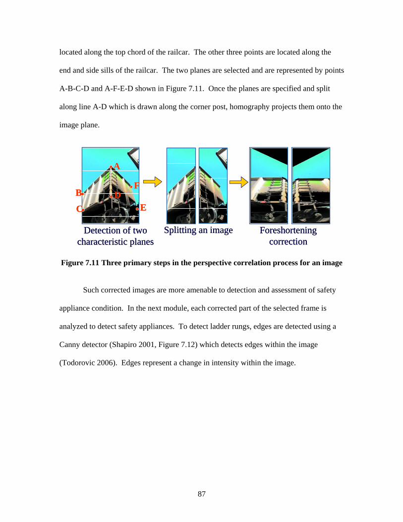
87
located along the top chord of the railcar. The other three points are located along the
end and side sills of the railcar. The two planes are selected and are represented by points
A-B-C-D and A-F-E-D shown in Figure 7.11. Once the planes are specified and split
along line A-D which is drawn along the corner post, homography projects them onto the
image plane.
Detection of twocharacteristic planes
Foreshorteningcorrection
A
B
CD
E
F
Splitting an imageDetection of twocharacteristic planes
Foreshorteningcorrection
A
B
CD
E
F
Splitting an image
Figure 7.11 Three primary steps in the perspective correlation process for an image
Such corrected images are more amenable to detection and assessment of safety
appliance condition. In the next module, each corrected part of the selected frame is
analyzed to detect safety appliances. To detect ladder rungs, edges are detected using a
Canny detector (Shapiro 2001, Figure 7.12) which detects edges within the image
(Todorovic 2006). Edges represent a change in intensity within the image.
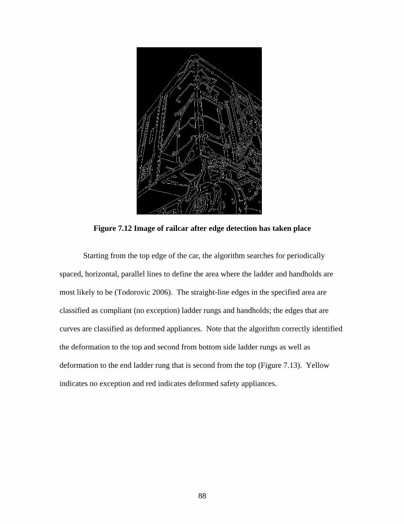
88
Figure 7.12 Image of railcar after edge detection has taken place
Starting from the top edge of the car, the algorithm searches for periodically
spaced, horizontal, parallel lines to define the area where the ladder and handholds are
most likely to be (Todorovic 2006). The straight-line edges in the specified area are
classified as compliant (no exception) ladder rungs and handholds; the edges that are
curves are classified as deformed appliances. Note that the algorithm correctly identified
the deformation to the top and second from bottom side ladder rungs as well as
deformation to the end ladder rung that is second from the top (Figure 7.13). Yellow
indicates no exception and red indicates deformed safety appliances.

89
Side EndSide End
Figure 7.13 Detection of ladder rungs and handholds on the side and end of a railcar
Additional examples of detected ladder rungs and handholds are presented in
Figure 7.14. The left images represent a newer gondola whereas the right images
represent an older hopper car that is highly deformed. The car on the right posed
additional recognition problems due to the horizontal parallel lines that are external ribs
on the side of the car. The algorithm was successfully modified to detect these hoppers.
Figure 7.14 Additional examples of detected ladder rungs and handholds
Detection and assessment of a brake-wheel does not require the perspective
correction because the appearance of the brake-wheel is sufficiently different from the
background, thus direct analysis of the original image is satisfactory. The algorithm
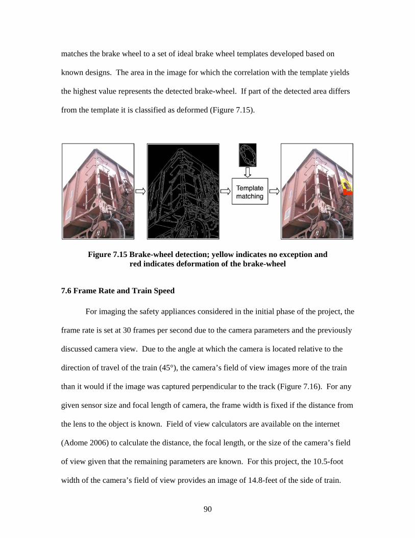
90
matches the brake wheel to a set of ideal brake wheel templates developed based on
known designs. The area in the image for which the correlation with the template yields
the highest value represents the detected brake-wheel. If part of the detected area differs
from the template it is classified as deformed (Figure 7.15).
Figure 7.15 Brake-wheel detection; yellow indicates no exception and red indicates deformation of the brake-wheel
7.6 Frame Rate and Train Speed
For imaging the safety appliances considered in the initial phase of the project, the
frame rate is set at 30 frames per second due to the camera parameters and the previously
discussed camera view. Due to the angle at which the camera is located relative to the
direction of travel of the train (45°), the camera’s field of view images more of the train
than it would if the image was captured perpendicular to the track (Figure 7.16). For any
given sensor size and focal length of camera, the frame width is fixed if the distance from
the lens to the object is known. Field of view calculators are available on the internet
(Adome 2006) to calculate the distance, the focal length, or the size of the camera’s field
of view given that the remaining parameters are known. For this project, the 10.5-foot
width of the camera’s field of view provides an image of 14.8-feet of the side of train.

91
The algorithm can tolerate images taken within a window of 40 pixels; +/- 20 pixels on
either side of the center of the image which represents 40/480 or 8.3% of the length of
train captured in each image.
To determine the limiting train speed using the set frame rate, we must first know
the maximum length of train that can pass between the capture of consecutive frames.
This is calculated as 8.3% x 14.8 ft = 1.23 ft. From this, the speed at which a train travels
1.23 ft in 1/30th of a second can be determined. This speed is 37.1 ft/sec or 25.3 mph. If
railroad operations and inspection installation requirements necessitate recording at
greater than 25 mph, the frame rate must be increased accordingly. For each doubling of
the speed of the train, the frame rate must also double. In order to achieve a frame rate of
60 frames per second (double the current frame rate) more sophisticated cameras may be
needed.
14.8’
Railcar
Railcar
7’
Camera
Field of View
14.8’
Railcar
Railcar
7’
Camera
Field of View
Figure 7.16 Plan view showing the camera’s field of view and the length of railcar captured during the imaging process

92
7.7 Methods for Obtaining Images of Deformed Railcar Safety Appliances
A large number of images of deformed safety appliances are needed to develop
the learning algorithm. Because of the relatively low rate at which safety appliance
defects occur, the acquisition of a sufficient number of these images would take a long
time. To accelerate this process other collection methods are being pursued.
7.7.1 Manual Deformation of Railcar Safety Appliances
One way that images of deformed safety appliances were obtained was to damage
an open-top hopper car under controlled conditions at the Transportation Technology
Center (TTC) Facility for Accelerated Service Testing (FAST) near Pueblo, CO.
Damage representative of what is often encountered in the field was inflicted on one of
each safety appliance on the railcar (Figures 7.10, 7.13, and 7.15) using hammers, chains,
and a forklift. After the car was damaged, it was operated around the FAST Track as part
of a 15-car test train made up of open-top hoppers and gondolas. Digital video of the
train was recorded at two locations on the FAST loop track to take advantage of the
ambient lighting conditions.
7.7.2 Three Dimensional Modeling of Railcar Safety Appliances
Another method of generating images of safety appliance damage is through the
use of a virtual model that allows for modeling of safety appliance deformation 1) under
varying lighting conditions, 2) on multiple car types, and 3) from differing camera views
and angles.
93
Autodesk’s® 3DS MAX 8 computer modeling software was used to create a three
dimensional model of an open-top hopper car. 3DS MAX 8 allows the user flexibility in
depicting different camera views and angles, as well as in depicting realistic lighting
conditions. Additionally, the program provides a means of generating both still images
and AVI files of the railcar model. A comparison of an actual camera and an image from
the 3D model is shown in Figure 7.17.
7.7.2.1 Lighting and Camera Specifics
Within 3DS MAX, cameras can be located at any user-defined location within the
model space. The resolution of the camera is set by the user and the field of view is set
by changing the camera’s distance from the railcar. The model allowed me to determine
the optimal camera angle once the view was selected. This was accomplished by running
the algorithm on numerous images taken from angles below the top of rail. All of the
images tested were at a 45º horizontal angle with respect to the track.
7.7.2.2 Model Uses
Visual learning is being used to categorize deformation to a railcar’s safety
appliances. Using this approach, it is necessary to gather hundreds of images
representing defective safety appliances to teach the algorithm the difference among the
various defect classes. Gathering these images in the field is tedious and labor intensive.
Each time a train is imaged in the field we obtain a large number of images of which only
a small percentage, one percent or less, contain safety appliance deformation. Using the
model, it is not only possible to simulate the railroad environment lighting, but also

94
generate hundreds of types of deformation that would be difficult to gather by imaging
real trains. Information regarding typical types of safety appliance deformation will be
gathered from railroad mechanical personnel ensuring that the algorithms will be tailored
to the recognition tasks that it will be required to perform.
Figure 7.17 Views of a railcar after deformation was inflicted in a controlled environment (left) and the corresponding 3D model showing the deformation (right)
The use of a virtual model increases the robustness of the machine vision
algorithm by allowing generation of images under varying lighting conditions. Of the
many lighting types provided within 3DS 8, two types are of interest for this project. The
first is omni light, and consists of light having an intensity that is inversely proportional
to the distance between the light and target. Omni light is the best representation of what
an artificial spotlight would provide for this application. Secondly, sky light is analogous
to sunlight in that the intensity does not decrease as the distance from the light source to

95
the target increases. If the model is verified on one car type it should be able to be
extrapolated to be used on other car types, saving time and expense compared to field
work.
Figure 7.18 shows the algorithmic result from the model car. The second ladder
rung from the bottom is not an FRA defect, but does have deformation. The sensitivity of
the algorithm can be adjusted to either recognize or filter out these types of minor
deformation. Eventually, use of visual learning will enable categorization of this as
deformed, but not an FRA violation.
Figure 7.18 Validation of algorithms on the model image which replicates the deformation seen in the actual image in Figure 7.17
Another use of the model is to predict the lighting conditions at a given location
given the coordinates (latitude/longitude), track orientation, and time of year. This helps
determine the best camera location when planning field visits to capture images during
the research stages of this project. It may also aid in planning the design of permanent
field installations.
Side End
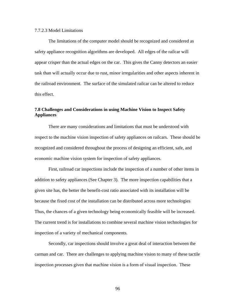
96
7.7.2.3 Model Limitations
The limitations of the computer model should be recognized and considered as
safety appliance recognition algorithms are developed. All edges of the railcar will
appear crisper than the actual edges on the car. This gives the Canny detectors an easier
task than will actually occur due to rust, minor irregularities and other aspects inherent in
the railroad environment. The surface of the simulated railcar can be altered to reduce
this effect.
7.8 Challenges and Considerations in using Machine Vision to Inspect Safety Appliances There are many considerations and limitations that must be understood with
respect to the machine vision inspection of safety appliances on railcars. These should be
recognized and considered throughout the process of designing an efficient, safe, and
economic machine vision system for inspection of safety appliances.
First, railroad car inspections include the inspection of a number of other items in
addition to safety appliances (See Chapter 3). The more inspection capabilities that a
given site has, the better the benefit-cost ratio associated with its installation will be
because the fixed cost of the installation can be distributed across more technologies
Thus, the chances of a given technology being economically feasible will be increased.
The current trend is for installations to combine several machine vision technologies for
inspection of a variety of mechanical components.
Secondly, car inspections should involve a great deal of interaction between the
carman and car. There are challenges to applying machine vision to many of these tactile
inspection processes given that machine vision is a form of visual inspection. These

97
interactions could consist of the carmen bending down to look under the car body for a
crack in the center sill or using a hammer to beat on a ladder rung to check for
securement. Based on field observations, carmen do not inspect each and every
appliance by tactile means. This would be far too involved for inbound car inspections
and is mainly used as a means of following up on cues from their visual inspection. Cues
should be identified that could aid a visual inspection system in detecting defects that
would normally be identified by tactile inspection methods. One cue could be the
deformation of a safety appliance, especially certain types that could signify poor
securement. Another indication of poor securement could be a rust streak from the bolted
connection between the safety appliance and the car body (Smith 2004). This would
require additional camera views and possibly a higher resolution than the 480x640
currently used in order to ensure that rust at connections farthest from the camera was not
in the range of noise.
Parallel to this discussion, consideration should be given to possibility of changes
to CFR Part 231 and the inspection requirements therein. This would involve a careful
analysis of the functional and safety requirements of each safety appliances. This
knowledge would be integrated with an understanding of the attributes of machine vision
(and other technologies) to develop new design and/or the specific inspection
requirements that enhanced both safety and efficiency.
Finally, the system must be robust to a variant of ambient lighting conditions in
order to justify the investment of such a system. Lighting is commonly one of the
greatest challenges in machine vision systems (Shapiro 2001). Machine vision systems
are sensitive to changing light conditions that pose threats to even the most refined

98
algorithms when extracting critical parts of a given image. Oftentimes, lighting must be
controlled by providing shelters or some means of artificial lighting. While this matter
may be accomplished with relative ease on an assembly line, it is non-trivial to adapt in
the railroad environment. For example, in the context of our current work, there is a
large area under the slope sheet on both ends of hopper cars that appears dark under many
lighting conditions. This area provides the background for the ladder and handholds.
Changing lighting conditions can cause the handholds to become completely undetectable
to the camera as they blend with the dark area under the slope sheet. Another example
relevant to this application occurs when the top chord of an open-top gondola or hopper
shadows the top ladder rungs during a large portion of the day. In many circumstances
artificial lighting will act to normalize the range of lighting conditions encountered in an
outdoor environment.
7.9 Other Methods of Detecting Safety Appliance Defects
7.9.1 Comparison of Opposite Corners
A potentially elegant alternative to developing algorithms to detect deformations
was considered. This approach would take advantage of the symmetry of opposite
corners of a railcar (Figure 8.1 explains that AR = BL and AL = BR). Images of the
opposite corners of a railcar would be recorded and overlayed on top of one another, and
any differences in the safety appliances would be assumed to be deformation (Figure
7.19). Unfortunately, this method proved to be less efficient than anticipated. Obtaining
the perfect alignment needed for image comparison was time consuming and appears to
involve much tighter tolerances regarding image perspective and composition than the

99
method previously described (Todorovic 2006). If the idea were to be implemented, the
images would have to be aligned dynamically (Todorovic 2006).
Figure 7.19 View of both the BL and AR corners of a covered hopper demonstrating the ease as to which the two opposite corners can be compared
This alignment would involve first selecting the same characteristic points on the
railcar as is needed before perspective correction; three along the top chord and three
along the end and side sill of the railcar (Figure 7.20).
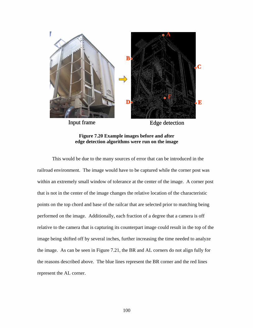
100
A
BC
D EF
Input frame Edge detection
AA
BBCC
DD EEFF
Input frame Edge detection
Figure 7.20 Example images before and after edge detection algorithms were run on the image
This would be due to the many sources of error that can be introduced in the
railroad environment. The image would have to be captured while the corner post was
within an extremely small window of tolerance at the center of the image. A corner post
that is not in the center of the image changes the relative location of the characteristic
points on the top chord and base of the railcar that are selected prior to matching being
performed on the image. Additionally, each fraction of a degree that a camera is off
relative to the camera that is capturing its counterpart image could result in the top of the
image being shifted off by several inches, further increasing the time needed to analyze
the image. As can be seen in Figure 7.21, the BR and AL corners do not align fully for
the reasons described above. The blue lines represent the BR corner and the red lines
represent the AL corner.

101
detaildetail
Figure 7.21 Example of overlayed BR and AL corners of a covered hopper car.
In conclusion, the computational time needed to perform matching exceeds the
amount of time needed to analyze each individual image. Furthermore, learning
algorithms would still need to be developed to analyze and characterize appliance
deformation, so no effort would be saved in the development of algorithms.
7.9.2 Analysis of Shadows to Determine Ladder Rung and Handhold Clearance
One of the most critical, and consistent, safety appliance parameters is the need
for two inches of clearances between handholds and ladder rungs and the car body. This
clearance is not visible from any location other than above or below the railcar. One
means by which the rung clearance would be visible is through the use of artificial
lighting mounted above or below the train and a camera located perpendicular to the
tracks. Depending on the intensity of the light, shadows will be cast on the car body and
the image would contain two lines for each ladder or handhold. Additional shadows
would be cast from the sun, and the algorithm would have to be capable of taking the

102
time of day and geographical location into consideration to determine whether or not the
visible shadow-depicted clearance is less than 2”. In summary, this method of
determining ladder rung and handhold clearance would allow for the ladder rung to be
inspected for deformation in two planes from a single camera view. It is the author’s
opinion that this method is less reliable than the perspective correction method discussed
earlier.
7.10 Future Work Prioritization
7.10.1 Prioritization of Additional Safety Appliances Additional appliances should be prioritized through the use of two types of data.
First, FRA inspection data should be used to determine the appliances that have the
largest numbers of defects. Secondly, Class I railroad data should be used to determine
which appliances result in the highest percentage of bad orders. Ideally, the railroad data
would be taken from a variety of locations throughout the industry to ensure that local car
handling techniques and car types do not give undue weight to certain types of safety
appliance problems.
7.10.2 Prioritization of Additional Car Types
There are several means by which additional car types can be prioritized. One
method would be to use Class I railroad bad order data. These data are generally broken
down by car type and would provide a guide as to which car types were bad ordered at
the highest rate. FRA defect data are not useful in prioritizing car types because the type
of car is not recorded in the FRA Inspection Database (FRA 2005).

103
Another method that could be used to prioritize car types is use of Wheel Impact
Load Detector (WILD) data. WILD data shows the number of times each car passes a
WILD installation during a set period of time (Figure 7.22).
0
20
40
60
80
100
120
140
160
Low P
rofile
Inter
modal
Flat C
ars
Stack C
ars
Conve
ntion
al Int
ermod
al
Gondo
la Car
– GT
Equipp
ed H
oppe
r
Loco
motive
Vehicu
lar Flat
Unequ
ipped
Hop
per
Refrige
rator
Cars
Equipp
ed G
ondo
la
Unequ
ipped
Gon
dola
Equipp
ed B
ox
Specia
l Typ
e Cars
Covere
d Hop
per
Unequ
ipped
Box
Tank C
ars
M-O-W
, Sca
le, P
asse
nger
Car Type
Num
ber o
f Pas
ses
Figure 7.22 Average number of visits to WILD sites between October 2004 and November 2005
Equipped gondolas, unequipped gondola, and unequipped hoppers have had
safety appliances successfully identified on them using machine vision algorithms. The
data in Table 7.2 indicates that low profile cars are passing by the WILD detectors most
frequently.
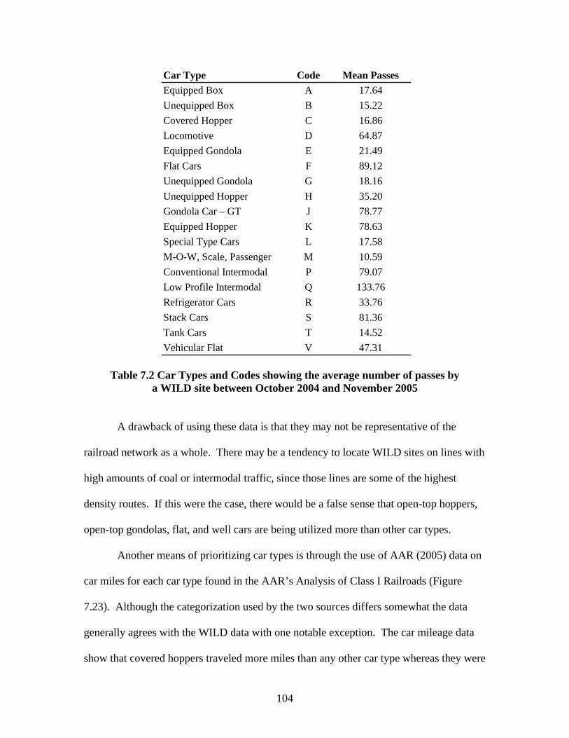
104
Car Type Code Mean PassesEquipped Box A 17.64Unequipped Box B 15.22Covered Hopper C 16.86Locomotive D 64.87Equipped Gondola E 21.49Flat Cars F 89.12Unequipped Gondola G 18.16Unequipped Hopper H 35.20Gondola Car – GT J 78.77Equipped Hopper K 78.63Special Type Cars L 17.58M-O-W, Scale, Passenger M 10.59Conventional Intermodal P 79.07Low Profile Intermodal Q 133.76Refrigerator Cars R 33.76Stack Cars S 81.36Tank Cars T 14.52Vehicular Flat V 47.31
Table 7.2 Car Types and Codes showing the average number of passes by
a WILD site between October 2004 and November 2005
A drawback of using these data is that they may not be representative of the
railroad network as a whole. There may be a tendency to locate WILD sites on lines with
high amounts of coal or intermodal traffic, since those lines are some of the highest
density routes. If this were the case, there would be a false sense that open-top hoppers,
open-top gondolas, flat, and well cars are being utilized more than other car types.
Another means of prioritizing car types is through the use of AAR (2005) data on
car miles for each car type found in the AAR’s Analysis of Class I Railroads (Figure
7.23). Although the categorization used by the two sources differs somewhat the data
generally agrees with the WILD data with one notable exception. The car mileage data
show that covered hoppers traveled more miles than any other car type whereas they were

105
ranked 15th in frequency among car types passing WILD sites. Intermodal flats and
equipped gondolas ranked 2nd and 3rd which is similar to the WILD data. These data are
also consistent with the hypothesis that WILD sites are located on routes that see high
volumes of coal and intermodal traffic.
0
1,000,000
2,000,000
3,000,000
4,000,000
5,000,000
6,000,000
7,000,000
Covere
d Hop
per
Flat TOFC/C
OFC
Gondo
la - P
lain
Box - E
quipp
ed
Flat M
ulti-L
evel
Open H
oppe
r - S
pecia
l Serv
ice
All Othe
r Typ
es
Open H
oppe
r - G
enera
l Serv
ice
Tanks
Flat A
ll Othe
r
Gondo
la - E
quipp
ed
Box - P
lain 5
0'
Refrige
rator
- Non
-Mec
hanic
al
Refrige
rator
- Mec
hanic
al
Flat G
enera
l Serv
ice
Box - P
lain 4
0'
Car Type
Tota
l Car
Mile
s
Figure 7.23 Car miles traveled by car type in 2004 (AAR 2005)
In summary, a combination of railroad bad order data, WILD data, and AAR car
mileage data should be used to determine which car type(s) algorithm development
should focus on to provide the most benefit to the railroads as resources become available
for development and implementation of this technology.
106
CHAPTER 8: INTERIM APPROACH TO MACHINE VISION INSPECTION OF RAILCAR SAFETY APPLIANCES
Development of a fully functional machine vision safety appliance inspection
system is likely to take a number of years. However, there is an interim approach that
would have the dual benefit of improving the efficiency of railcar inspection in the short
term, and accelerating the longer term development of machine vision safety appliance
inspection technology.
8.1 Overview of Interim System
In this interim system, videos of trains would be recorded using a digital video
camera in the same manner used in the tests already described. The current image
selection algorithms would be used to extract optimal images from the frame sequence
that provide the best view of safety appliances and their respective parameters outlined in
Part 231. Once the optimal images are extracted, they would be analyzed manually by
carmen viewing a computer monitor who would note damage to safety appliances. The
carmen would flag any railcars they suspect of having defects for follow up inspection,
repair in the yard, or bad ordering cars straight to a repair track.
8.2 Installation
The installation should be at a location that allows trains to be recorded as they
enter a yard. If located outside the yard and if the train speed will be higher than 25 mph
then a frame rate greater than 30 frames per second would need to be used. The time
needed for mechanical personnel to view the images, interpret the information, and

107
develop a method of handling the incoming train must be considered as well as
developing a process for handling any possible defects detected. The relay of
information may simply include a carman printing out a sheet with a list of the cars and
their respective defects, or the relay could be accomplished by downloading this
information to a PDA for use by a carman. Once the location is selected based on the
above factors, four cameras would be needed to obtain images of the four corners of the
railcar (Figure 8.1).
AL
BR
B EndA End
Left Side
Right Side
AR
BL
Railcar
B‐EndA‐End
AL
BR
AL
BR
B EndA End
Left Side
Right Side
AR
BL
AR
BL
AR
BL
Railcar
B‐EndA‐End
Figure 8.1 Camera views for interim machine vision installation of railcar safety appliances
As the four cameras collect the images they will be saved in AVI format. After
the video is collected the frames must be extracted before the optimal images will be
selected from the image sequence. The optimal image for a given corner of a railcar is

108
the one in which the corner post is in the leading position and vertically oriented in the
center of the image.
8.3 Image Analysis
When the four optimal images are selected for each railcar, they should be
grouped into two pairs for each car. These pairs represent the AL and BR corners and the
AR and BL corners. These respective pairs of corners are identical in terms of their
safety appliance configuration with the exception of the presence of the brake wheel in
the B-end views of the car (Figures 8.2, 8.3, and 8.4).
BL AR
Figure 8.2 View of the BL and AR corners of a hopper demonstrating the ease of comparison of like elements of the safety appliances
Most cars have two corners with ladders and two corners with only handholds or
modified ladders. Once the two like images are grouped side by side, they can be

109
examined and easily compared by carmen. In Figure 8.2 it is evident that the AR corner
of the car has had extensive repairs made on its side ladder although there are no safety
appliance defects on either corner. Carmen will be looking for aspects of the railcar
corners that look different in the two images rather than looking at each corner separately
and searching for defects. Most cars will be similar to Figure 8.3 in that there is no
deformation and the two corners will appear alike.
Simultaneous viewing and comparison of like images may improve both the
accuracy and speed of safety appliance inspection. The interim system employs the
image acquisition hardware, but retains the human brain as the processor to interpret the
images. As such, it could be considered as a technological aid to carmen performing
inspections as discussed in Chapter 5.
BL AR
Figure 8.3 View of the BL and AR corners of a hopper showing no deformed safety appliances

110
BR AL
Figure 8.4 View of the BR and AL corners of a hopper showing no deformed safety appliances
An advantage of the interim installation is that it allows like corners to be simultaneously
compared from identical viewing angles which is not possible with the current inspection
process.
As with the final system, one of the challenges to an interim system such as
described here involves lighting. There are often instances when the top chord of a
gondola or hopper casts a shadow on the upper ladder rung and other instances when the
ambient lighting is not adequate. In order for the interim installation to be cost justified
artificial lighting would need to be incorporated to allow for operation 24 hours per day
and under a variety of lighting conditions. Among the advantages of the system is that
carmen will be able to observe the flow of images from a location, protected from the

111
elements and isolated from hazards. This might lead to a reduction in certain types of
injuries that occur in yards
As mentioned above, another benefit to an interim machine vision system is that it
will provide a flow of images that are needed to train the algorithms for the fully
functional, automated, machine vision safety appliance inspection system. Currently, the
vast majority of safety appliance images are not in violation of CFR Part 231, but as
discussed in Chapter 7, training the algorithm will require thousands of images of
deformed and defective appliances to be captured. An interim installation such as
described here would provide that flow of images and at the same time provide near-term
benefit to railroads by improving the efficiency, effectiveness, and possibly the safety of
the current inspection process.
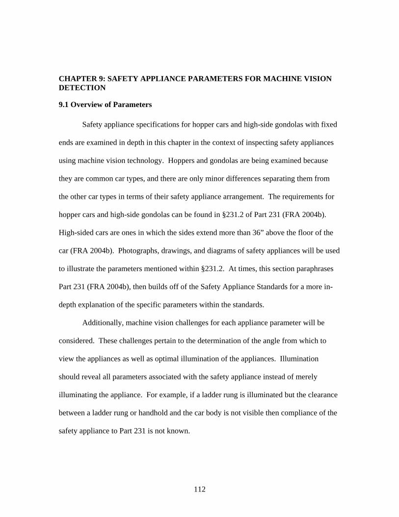
112
CHAPTER 9: SAFETY APPLIANCE PARAMETERS FOR MACHINE VISION DETECTION
9.1 Overview of Parameters
Safety appliance specifications for hopper cars and high-side gondolas with fixed
ends are examined in depth in this chapter in the context of inspecting safety appliances
using machine vision technology. Hoppers and gondolas are being examined because
they are common car types, and there are only minor differences separating them from
the other car types in terms of their safety appliance arrangement. The requirements for
hopper cars and high-side gondolas can be found in §231.2 of Part 231 (FRA 2004b).
High-sided cars are ones in which the sides extend more than 36” above the floor of the
car (FRA 2004b). Photographs, drawings, and diagrams of safety appliances will be used
to illustrate the parameters mentioned within §231.2. At times, this section paraphrases
Part 231 (FRA 2004b), then builds off of the Safety Appliance Standards for a more in-
depth explanation of the specific parameters within the standards.
Additionally, machine vision challenges for each appliance parameter will be
considered. These challenges pertain to the determination of the angle from which to
view the appliances as well as optimal illumination of the appliances. Illumination
should reveal all parameters associated with the safety appliance instead of merely
illuminating the appliance. For example, if a ladder rung is illuminated but the clearance
between a ladder rung or handhold and the car body is not visible then compliance of the
safety appliance to Part 231 is not known.

113
As previously discussed, Part 231 addresses many aspects of safety appliances
and the relevant parameters found there can be divided into either quantitative or
qualitative. For the most part, a machine vision system, like car inspectors who currently
perform car inspections, would focus on the quantitative parameters. These quantitative
parameters consist of the various distances (length, spacing, areas, and clearances).
Qualitative parameters primarily pertain to material types and there is little need or use
for a vision system to detect these parameters. A vision-based system should be capable
of monitoring the quantitative parameters covered in the safety appliance standards.
These quantitative parameters can be subdivided into two categories; design and dynamic
parameters.
Design parameters are ones that should have been met when the car was built or
rebuilt. In those instances of design parameters that were not met when cars were built
FRA inspectors generally do not take exception to these violations if they have not
caused a problem as discussed in Chapter 3. As new cars are designed, the safety
appliance aspects of the car must be approved by the FRA prior to construction of the car
as a part of a sample car inspection (FRA 2004a), so there is little chance that new cars
are being constructed with safety appliances that violate FRA regulations. An example
of a design parameter would be the length of a ladder rung. It is highly unlikely that this
aspect of a ladder rung could be damaged to such an extent that it would violate CFR Part
231.
Dynamic parameters are ones that are most likely to be violated during the
everyday movement of the railcar. These parameters were determined through field
visits in which Class I railroad mechanical management and carmen identified safety

114
appliance parameters that were typically encountered in the yard and repair facilities.
Unlike ladder rung length, there is a chance that the required 2” clearance between the
ladder rung and car body can be altered as a car is moved.
For each safety appliance, the dynamic parameters are identified with red text
boxes and arrows, and the design parameters are identified by blue text boxes and arrows.
9.2 Handbrake
The handbrake is used to manually apply the brakes on a railcar and basically
serves as a “parking brake”. The brakes are applied by turning the hand brake wheel,
which, through a series of chains and rods, apply force to the brake shoe against the tread
of the wheel. Examples of hand brakes, brake wheels, and their configuration are shown
in Figures 9.1 and 9.2.
Figure 9.1 Images of the brake wheel
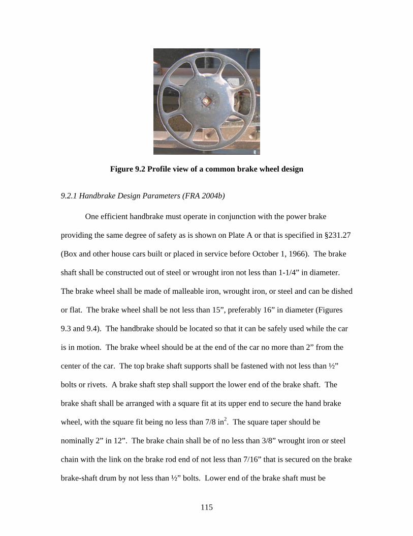
115
Figure 9.2 Profile view of a common brake wheel design
9.2.1 Handbrake Design Parameters (FRA 2004b)
One efficient handbrake must operate in conjunction with the power brake
providing the same degree of safety as is shown on Plate A or that is specified in §231.27
(Box and other house cars built or placed in service before October 1, 1966). The brake
shaft shall be constructed out of steel or wrought iron not less than 1-1/4” in diameter.
The brake wheel shall be made of malleable iron, wrought iron, or steel and can be dished
or flat. The brake wheel shall be not less than 15”, preferably 16” in diameter (Figures
9.3 and 9.4). The handbrake should be located so that it can be safely used while the car
is in motion. The brake wheel should be at the end of the car no more than 2” from the
center of the car. The top brake shaft supports shall be fastened with not less than ½”
bolts or rivets. A brake shaft step shall support the lower end of the brake shaft. The
brake shaft shall be arranged with a square fit at its upper end to secure the hand brake
wheel, with the square fit being no less than 7/8 in2. The square taper should be
nominally 2” in 12”. The brake chain shall be of no less than 3/8” wrought iron or steel
chain with the link on the brake rod end of not less than 7/16” that is secured on the brake
brake-shaft drum by not less than ½” bolts. Lower end of the brake shaft must be

116
provided with a trunnion no less than ¾” in diameter extending through the brake-shaft
step and held in operating position by a suitable cotter or ring. The brake-shaft drum
shall be not less than 1-1/2” in diameter. The brake ratchet wheel shall be secured to the
brake shaft with a square fit of no less than 1-5/16”. Brake ratchet wheel shall be no less
than 5-1/4” in diameter and must have no less than 14 teeth. If the brake wheel ratchet is
more than 36” from the brake wheel a brake wheel supports shall be provided fastened
with ½” bolts or rivets. The brake pawl shall be pivoted upon a bolt with a minimum
diameter of 5/8”, with a trunnion secured by no less than ½” bolt or rivet, with a rigid
connection between brake shaft and pivot of pawl. The brake wheel shall be held in
place by a nut on the extended end of the brake shaft that is no less than ¾” in diameter
with the nut riveted. The brake wheel is arranged with a square fit for brake shaft in the
hum of wheel; taper of said fit, nominally 2-½”.
The brake wheel shall be flat or dished, not less than 15”, preferably 16” in diameter
Each car should have one efficient hand brake which operates in harmony with the power brake
Distance from brake shaft to the center of the car can be no more than 22” allowing for safe operation while train is in motion
The brake wheel shall be flat or dished, not less than 15”, preferably 16” in diameter
The brake wheel shall be flat or dished, not less than 15”, preferably 16” in diameter
Each car should have one efficient hand brake which operates in harmony with the power brake
Distance from brake shaft to the center of the car can be no more than 22” allowing for safe operation while train is in motion
Distance from brake shaft to the center of the car can be no more than 22” allowing for safe operation while train is in motion
Figure 9.3 Brake wheel parameters
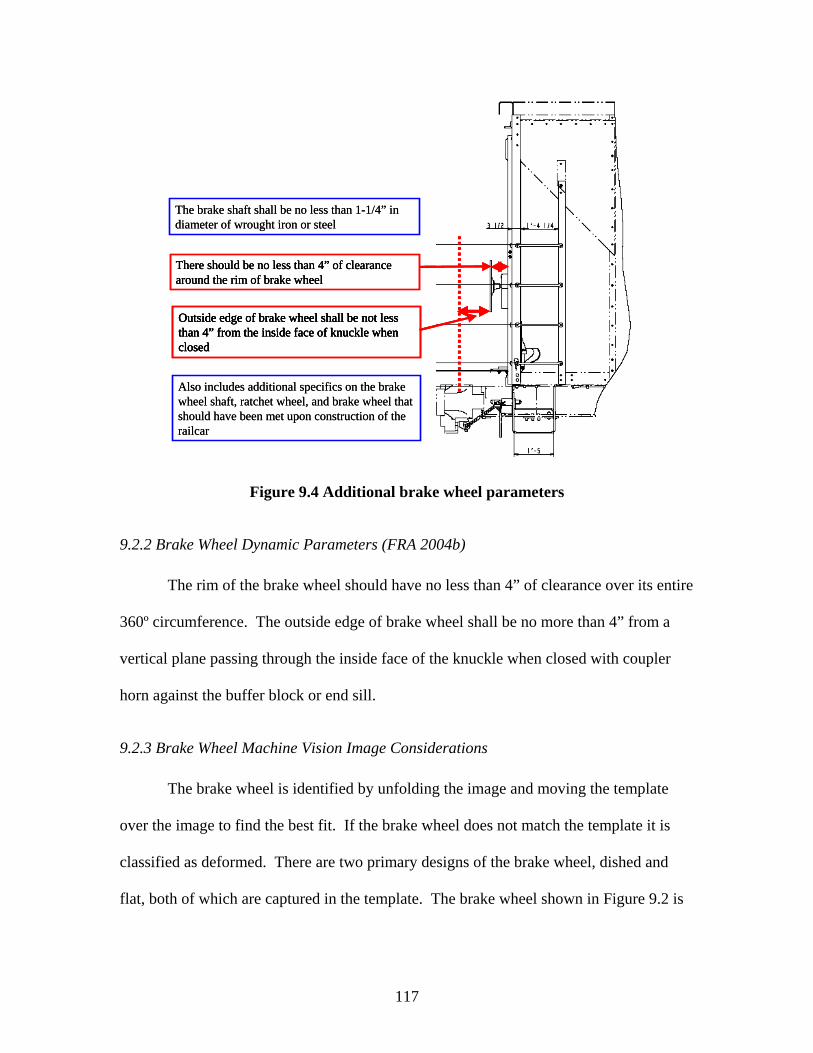
117
Also includes additional specifics on the brake wheel shaft, ratchet wheel, and brake wheel that should have been met upon construction of the railcar
The brake shaft shall be no less than 1-1/4” in diameter of wrought iron or steel
There should be no less than 4” of clearance around the rim of brake wheel
Outside edge of brake wheel shall be not less than 4” from the inside face of knuckle when closed
Also includes additional specifics on the brake wheel shaft, ratchet wheel, and brake wheel that should have been met upon construction of the railcar
The brake shaft shall be no less than 1-1/4” in diameter of wrought iron or steel
There should be no less than 4” of clearance around the rim of brake wheel There should be no less than 4” of clearance around the rim of brake wheel
Outside edge of brake wheel shall be not less than 4” from the inside face of knuckle when closed
Outside edge of brake wheel shall be not less than 4” from the inside face of knuckle when closed
Outside edge of brake wheel shall be not less than 4” from the inside face of knuckle when closed
Figure 9.4 Additional brake wheel parameters
9.2.2 Brake Wheel Dynamic Parameters (FRA 2004b)
The rim of the brake wheel should have no less than 4” of clearance over its entire
360º circumference. The outside edge of brake wheel shall be no more than 4” from a
vertical plane passing through the inside face of the knuckle when closed with coupler
horn against the buffer block or end sill.
9.2.3 Brake Wheel Machine Vision Image Considerations The brake wheel is identified by unfolding the image and moving the template
over the image to find the best fit. If the brake wheel does not match the template it is
classified as deformed. There are two primary designs of the brake wheel, dished and
flat, both of which are captured in the template. The brake wheel shown in Figure 9.2 is

118
of the flat type. Two manufacturers of brake wheels are Cardwell Westinghouse and
Ellcon-National, a subsidiary of Wabtec Company.
An alternative means of measuring brake wheel clearance should be through the
use of an image that is perpendicular to the side of the train (Figure 9.5). The frame rate
must be high enough to ensure that an image is captured when the brake wheel is
perfectly in line with the camera target, or within a very small tolerance that would allow
for accurate measurement of clearance.
Figure 9.5 Brake wheel viewed from perpendicular to the track showing brake wheel clearance
During much of the day the brake wheel will be in the shadow cast by an adjacent
car in the train. The possibility of imaging the railcar from the side may allow the brake
wheel to be more visible given the relative light from the background, but may introduce
difficulties regarding dynamic backgrounds that have been encountered in other machine

119
vision projects (Lai et al 2004). Movement of trees, clouds, other trains, or any other
objects that might be visible through the gap between two railcars can make background
distinction difficult. A backdrop is one solution to this problem.
If the brake wheel is deformed, the clearance at any point in a complete rotation
of the brake wheel must meet or exceed the FRA requirement. There are several
approaches to determining whether or not brake wheel clearance is violated. The first of
these would be through exact measurement. This is not feasible because while clearance
may not be violated at the time the train passes, the brake wheel could be rotated into a
position in which clearance is not met. The approach used in this research is to use
template matching to flag any deformation and then allow learning to handle the
categorization between FRA defects and deformation that does not constitute an FRA
violation. Figure 9.6 shows a brake wheel that does not satisfy the 4” clearance
requirement prescribed by CFR Part 231.
Figure 9.6 Brake wheel with insufficient clearance per CFR Part 231
120
9.3 Brake Step
The brake step provides a platform for a railroad employee to safely operate the
handbrake. It is located immediately below the brake wheel on a railcar and extends
beyond the brake wheel on either side (Figure 9.7). The platform is generally constructed
of some type of grating to provide a more slip resistant surface under all conditions.
Figure 9.7 Example images of the brake step and brake wheel
9.3.1 Brake Step Design Parameters (FRA 2004b)
The brake step should be supported by not less than two metal braces having a
minimum cross sectional area 3/8” by 1-1/2” or equivalent secured with no less than ½”
bolts or rivets (Figures 9.8 and 9.9).
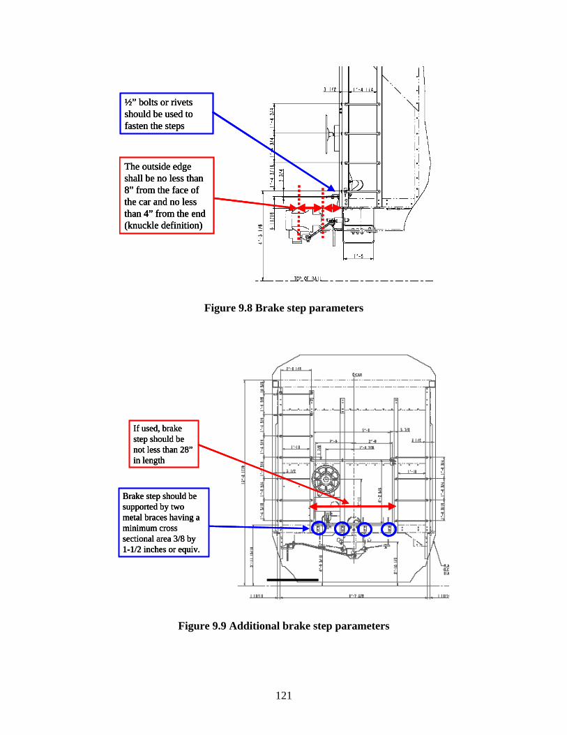
121
½” bolts or rivets should be used to fasten the steps
The outside edge shall be no less than 8” from the face of the car and no less than 4” from the end (knuckle definition)
½” bolts or rivets should be used to fasten the steps
½” bolts or rivets should be used to fasten the steps
The outside edge shall be no less than 8” from the face of the car and no less than 4” from the end (knuckle definition)
The outside edge shall be no less than 8” from the face of the car and no less than 4” from the end (knuckle definition)
Figure 9.8 Brake step parameters
If used, brake step should be not less than 28” in length
Brake step should be supported by two metal braces having a minimum cross sectional area 3/8 by 1-1/2 inches or equiv.
If used, brake step should be not less than 28” in length
If used, brake step should be not less than 28” in length
Brake step should be supported by two metal braces having a minimum cross sectional area 3/8 by 1-1/2 inches or equiv.
Brake step should be supported by two metal braces having a minimum cross sectional area 3/8 by 1-1/2 inches or equiv.
Figure 9.9 Additional brake step parameters

122
9.3.2 Brake Step Dynamic Parameters (FRA 2004b)
If a brake step is used, it should be no less than 28” in length. The outer edge of
the brake step should be no more than 8” from face of car and no less than 4” from a
vertical plane parallel with end of car and passing through the inside face of the knuckle
when closed with coupler horn against the buffer block or end sill. Another possibility
for a dynamic parameter would be securement of the brake step to the car body. It is
unlikely that the brake step would not be supported by the required number of braces, but
it is possible that one of the braces could become insecure.
9.3.3 Brake Step Machine Vision Image Considerations There are multiple possible views when it comes to imaging the brake step. First,
if a camera were mounted perpendicular to the railcar in line with the brake step (Figure
9.10), it is possible that deformation in the vertical plane could be identified.
Figure 9.10 Image of the brake step taken perpendicular to the tracks and in-line with the brake step

123
Instead of a perpendicular view, one that is perpendicular to the tracks and above the
brake step should also be considered, allowing the overall length and width of the brake
step to be captured in the image (Figure 9.11). From this angle the brake step has depth
and the necessary width and length parameters can be viewed allowing deformations to
be identified.
Figure 9.11 Image of the brake step taken perpendicular to the tracks and above the brake step showing the step’s length
If it is not possible to accurately identify deformations in both planes from a
single view, two views will have to be used; one taken from above the railcar, and the
other taken from the side. The top-down view of the brake step could provide the needed
angle to monitor the necessary parameters. A top-down view would provide the

124
necessary angle to check the length and width of the brake step as well as brake wheel
clearance. If there were a camera both above and beside the train, the two images could
be compared to detect all deformation associated with the brake step.
As with the brake wheel, the area in which the brake step is located is not easily
illuminated during a large portion of the day which suggests the need to use a
perpendicular image. The perpendicular image is backlit and introduces potential
background problems but allows the relatively dark brake step to appear distinct from the
lighted background.
One of the challenges with the brake step is their range of heights on the end of
the car. The brake wheel is fixed in the horizontal plane on the end of the car, but it is
not fixed vertically allowing for a range in brake step locations. This does not present a
problem in recognizing the brake wheel since the algorithm is written to find the circular
brake wheel anywhere in the image without unfolding the image but could be a problem
with the brake step.
This section does not describe end platforms, which are oftentimes referred to as
crossover steps. End platforms are not required on open-top hoppers and gondolas, but
when the car is equipped with an end platform it is required to be in compliance with
CFR Part 231. End platforms are covered in §231.27, box and other house cars without
roof hatches or placed in service after October 1, 1966. They are required to be no less
than 8” in width and not less than 60” in length. They should be secured with no less
than 3 metal braces at a height of no more than 8” above the top of center sill. An
example of an end platform with significant deformation can be seen in Figure 9.12.

125
Figure 9.12 End platform on a boxcar showing significant deformation
9.4 Sill Steps
The sill steps provide a location from which a transportation employee can mount
a car on any of the four sides. Sill steps are the location where the employee’s feet often
rest while they hold on to the car’s handholds during movement of the railcar. Examples
of sill step designs are shown in Figures 9.13 and 9.14
Figure 9.13 Sill step without additional rung
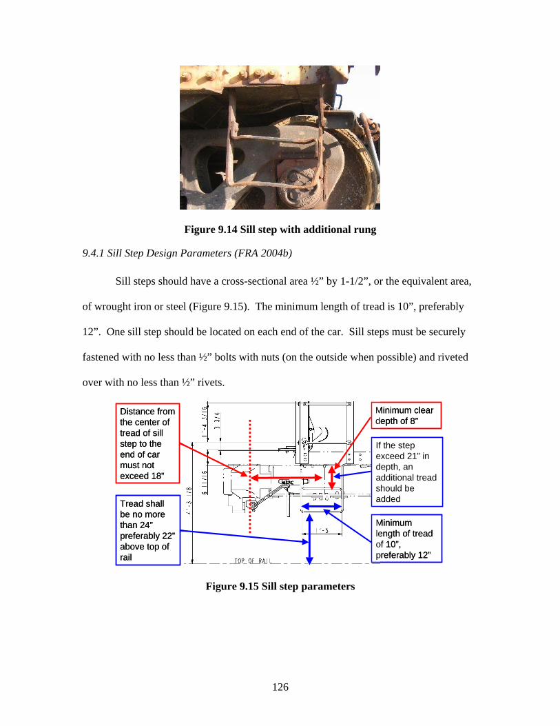
126
Figure 9.14 Sill step with additional rung
9.4.1 Sill Step Design Parameters (FRA 2004b)
Sill steps should have a cross-sectional area ½” by 1-1/2”, or the equivalent area,
of wrought iron or steel (Figure 9.15). The minimum length of tread is 10”, preferably
12”. One sill step should be located on each end of the car. Sill steps must be securely
fastened with no less than ½” bolts with nuts (on the outside when possible) and riveted
over with no less than ½” rivets.
If the step exceed 21” in depth, an additional tread should be added
Minimum clear depth of 8”
Minimum length of tread of 10”, preferably 12”
Distance from the center of tread of sill step to the end of car must not exceed 18”
Tread shall be no more than 24” preferably 22” above top of rail
If the step exceed 21” in depth, an additional tread should be added
Minimum clear depth of 8”
Minimum length of tread of 10”, preferably 12”
Distance from the center of tread of sill step to the end of car must not exceed 18”
Tread shall be no more than 24” preferably 22” above top of rail
Figure 9.15 Sill step parameters

127
9.4.2 Sill Step Dynamic Parameters (FRA 2004b)
The maximum clear depth of the sill step is 8”. The distance between the center
of the sill step and the end of car should be no more than 18”. The outside edge of the sill
step tread shall be no more than 4” inside the face of the car, preferably flush with the
edge of the car. The tread shall be no more than 24” above the top of the rail, preferably
no more than 22”. Sill steps with a depth (vertical height) greater than 21” must have an
additional tread (Figures 9.14, 9.15).
9.4.3 Sill Step Machine Vision Image Considerations Sill steps are one of the most challenging safety appliances to identify defects
using machine vision. This challenge results from the shape, location, and background
behind the sill steps. There are three primary designs of sill steps (Figures 9.13, 9.14,
9.16) with many subcategories due to differing means of attachment. Occasionally, these
designs are changed to allow the sill step to be offset underneath the car (Figure 9.16).
Figure 9.16 Sill step offset underneath the railcar
128
This poses a problem for a vision system in that it is difficult to determine if a sill step is
offset by design or if it is deformed. One solution to this problem is only flagging the sill
step for deformation if the distance between the outside edge of the step and the edge of
the car is greater than four inches. The other solution will be supplying the learning
algorithm with exhaustive examples of sill steps that are offset by design as well as
deformed ones that look similar to offset sill steps. The effectiveness of the algorithm at
distinguishing between the two should then be evaluated.
Using the angled camera view below the top of rail that was used for the analysis
of ladders, handholds, and the brake wheel is difficult because there is a great deal of
clutter behind the sill step making analysis by machine vision algorithms difficult
(Todorovic 2005). Clutter refers to other parts of the railcar that are not safety appliances
and appear in the image behind the sill step. Clutter may consist of brake rigging, the
truck, or other mechanical car components.
One view that could be effective in detecting sill step deformation is shown in
Figure 9.17. This view is taken from an angle that is more acute with regard to the track
(i.e. less than 45°) than the images taken from the initial camera view. This would
provide better definition of deformations in the plane of the side of the car body. This
angle does not allow the distance between the center of the sill step and the end of the car
to be viewed, but would allow for the measurement of distances between rungs as well as
the distance to the top of rail – both of which are dynamic parameters that will need to be
assessed.

129
Figure 9.17 Sill step viewed from shallow angle to show sill step deformation
Sill step deformation may come in many forms as shown in Figure 9.18. The
image on the left shows an FRA defect whereas the image on the right shows
deformation that is not an FRA defect.
Figure 9.18 Sill step deformation showing an FRA defect (left) and significant deformation (right)

130
9.5 Ladders
Ladders are used by employees to mount a railcar, ride a railcar, and obtain access
to the roof or brake wheel of the railcar if necessary (Figure 9.19). Employees use both
hands and feet when using the ladder treads. Certain lower treads of the side and end
ladders are considered side and end handholds per the FRA regulations and will be
identified below.
Figure 9.19 Images of the side ladder (left) as well as an image of both the side and end ladders (right) on open-top hopper cars
9.5.1 Ladder Design Parameters (FRA 2004b)
The minimum clear length of tread is 16” for side ladders, 14” for end ladders
(Figures 9.20 and 9.21). The height of end ladder treads shall coincide with side ladder
treads, with a variance of no more than 2” allowed. If construction does not permit the
bottom treads to coincide, the bottom tread on the end ladder should coincide with the
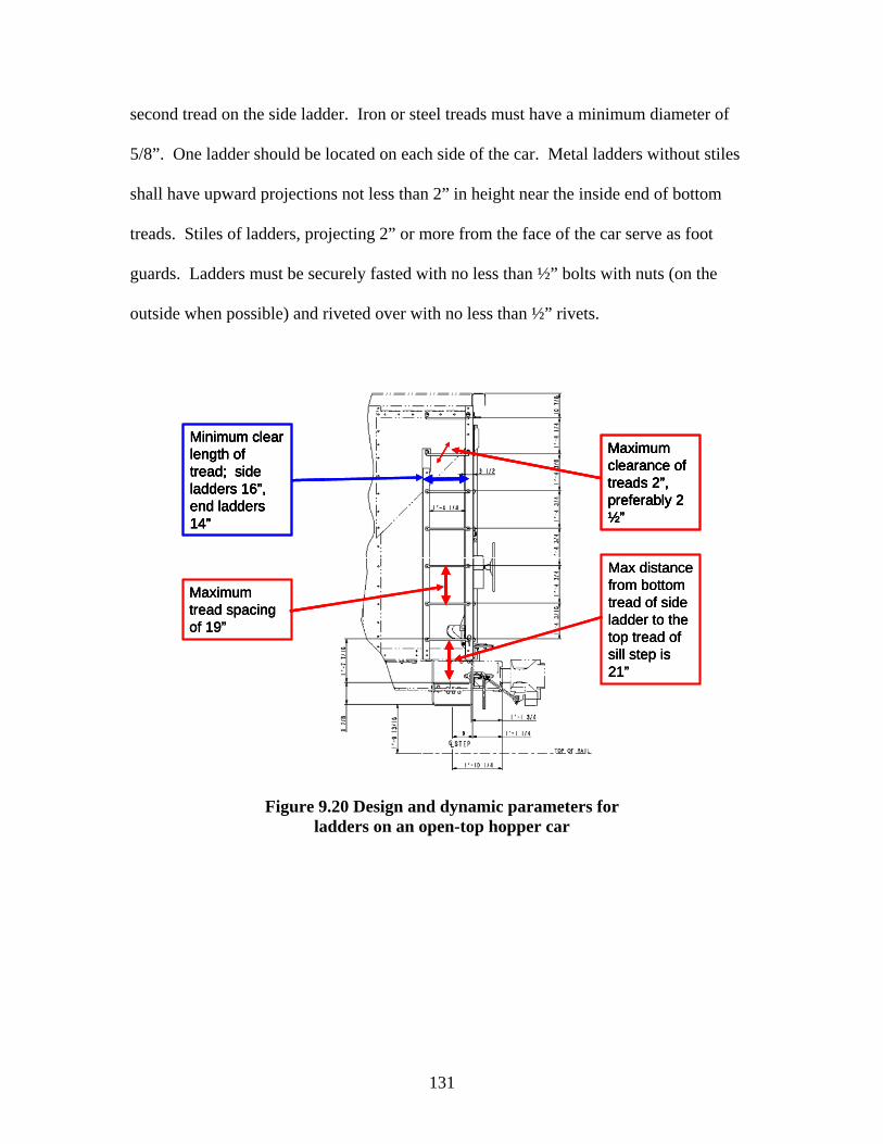
131
second tread on the side ladder. Iron or steel treads must have a minimum diameter of
5/8”. One ladder should be located on each side of the car. Metal ladders without stiles
shall have upward projections not less than 2” in height near the inside end of bottom
treads. Stiles of ladders, projecting 2” or more from the face of the car serve as foot
guards. Ladders must be securely fasted with no less than ½” bolts with nuts (on the
outside when possible) and riveted over with no less than ½” rivets.
Maximum clearance of treads 2”, preferably 2 ½”
Minimum clear length of tread; side ladders 16”, end ladders 14”
Max distance from bottom tread of side ladder to the top tread of sill step is 21”
Maximum tread spacing of 19”
Maximum clearance of treads 2”, preferably 2 ½”
Maximum clearance of treads 2”, preferably 2 ½”
Maximum clearance of treads 2”, preferably 2 ½”
Minimum clear length of tread; side ladders 16”, end ladders 14”
Minimum clear length of tread; side ladders 16”, end ladders 14”
Minimum clear length of tread; side ladders 16”, end ladders 14”
Max distance from bottom tread of side ladder to the top tread of sill step is 21”
Max distance from bottom tread of side ladder to the top tread of sill step is 21”
Maximum tread spacing of 19”
Maximum tread spacing of 19”
Figure 9.20 Design and dynamic parameters for ladders on an open-top hopper car

132
No more than 8” from the left and right ends of the car
Top ladder tread should be no more than 4” from top of car End ladders and
side ladders should coincide with one another with a 2” variation allowed
Spacing of ladder treads should be uniform within a 2”limit
Minimum tread diameters of 5/8”
Metal ladders without stiles near corners of cars shall have foot guards or upward projections not less than 2” in height near inside end of bottom treads
No more than 8” from the left and right ends of the car
No more than 8” from the left and right ends of the car
Top ladder tread should be no more than 4” from top of car
Top ladder tread should be no more than 4” from top of car End ladders and
side ladders should coincide with one another with a 2” variation allowed
End ladders and side ladders should coincide with one another with a 2” variation allowed
Spacing of ladder treads should be uniform within a 2”limit
Spacing of ladder treads should be uniform within a 2”limit
Minimum tread diameters of 5/8”
Minimum tread diameters of 5/8”
Metal ladders without stiles near corners of cars shall have foot guards or upward projections not less than 2” in height near inside end of bottom treads
Figure 9.21 Additional design and dynamic parameters for ladders on an open-top hopper car
9.5.2 Ladder Dynamic Parameters (FRA 2004b)
The maximum spacing between treads should be no more than 19”. The top
ladder tread shall be no more than 4” from the roof of the car at the eaves. Spacing of
ladder rungs should be uniform within a limit of 2” between the top and bottom ladder
treads. The maximum distance from the bottom tread of the side ladder to the top tread
of the sill step is 21”. The maximum clearance of treads is 2”, preferably 2-1/2”. The
ladder shall be no more than 8” from the left side of the car, measured from the inside
edge of the ladder stile or clearance of ladder stile to the corner of car.
9.5.3 Ladder Machine Vision Image Considerations
Ladders were part of the initial focus in safety appliance recognition using
machine vision. The algorithmic approach for locating ladders on open-top hoppers and
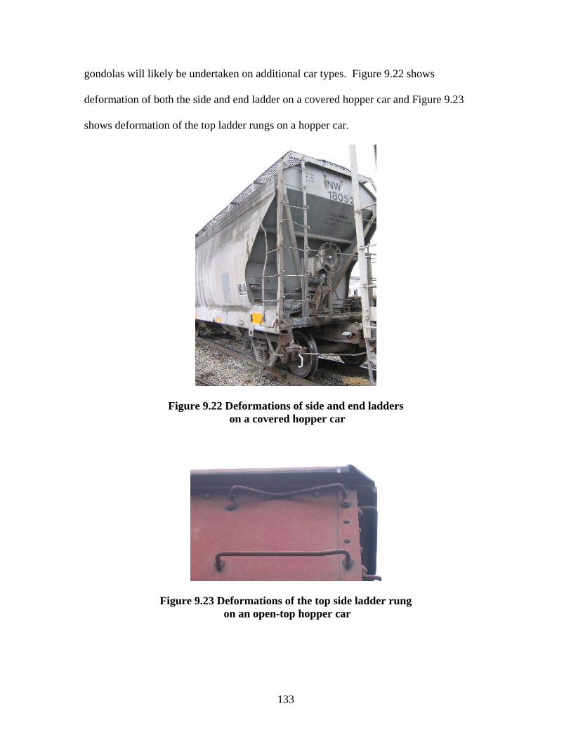
133
gondolas will likely be undertaken on additional car types. Figure 9.22 shows
deformation of both the side and end ladder on a covered hopper car and Figure 9.23
shows deformation of the top ladder rungs on a hopper car.
Figure 9.22 Deformations of side and end ladders on a covered hopper car
Figure 9.23 Deformations of the top side ladder rung on an open-top hopper car
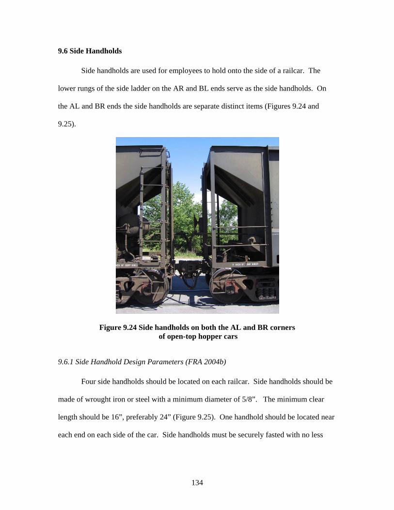
134
9.6 Side Handholds
Side handholds are used for employees to hold onto the side of a railcar. The
lower rungs of the side ladder on the AR and BL ends serve as the side handholds. On
the AL and BR ends the side handholds are separate distinct items (Figures 9.24 and
9.25).
Figure 9.24 Side handholds on both the AL and BR corners of open-top hopper cars
9.6.1 Side Handhold Design Parameters (FRA 2004b)
Four side handholds should be located on each railcar. Side handholds should be
made of wrought iron or steel with a minimum diameter of 5/8”. The minimum clear
length should be 16”, preferably 24” (Figure 9.25). One handhold should be located near
each end on each side of the car. Side handholds must be securely fasted with no less
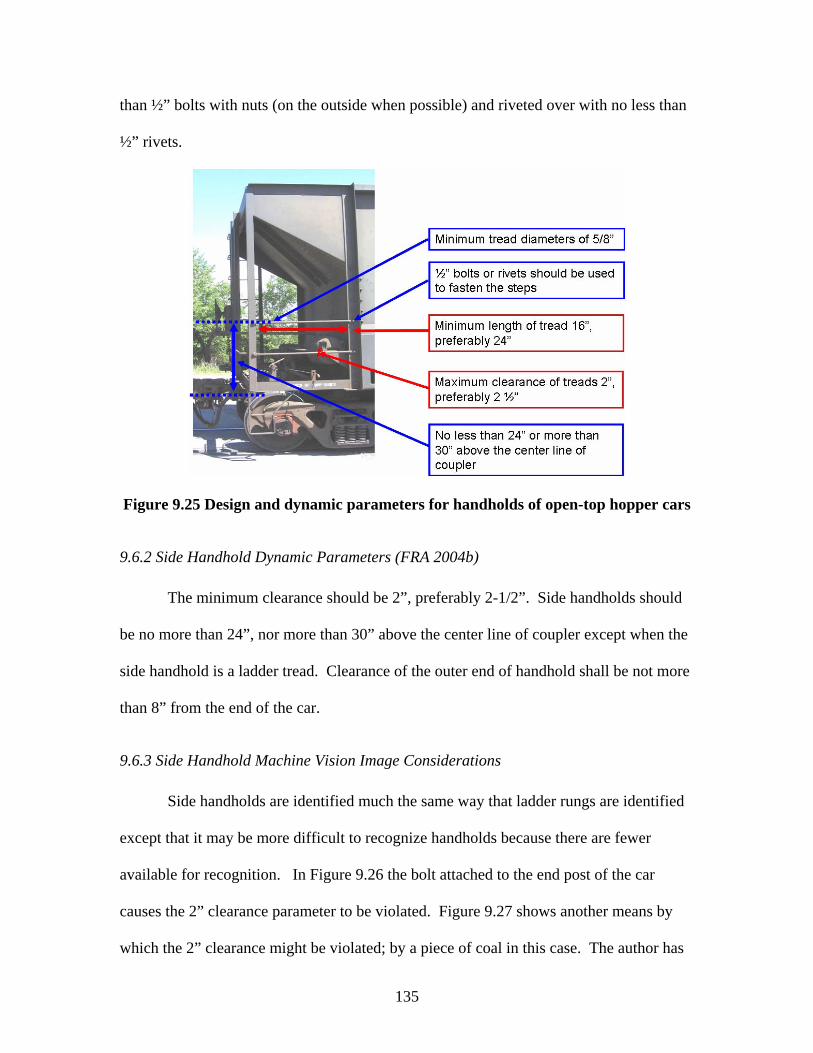
135
than ½” bolts with nuts (on the outside when possible) and riveted over with no less than
½” rivets.
Figure 9.25 Design and dynamic parameters for handholds of open-top hopper cars
9.6.2 Side Handhold Dynamic Parameters (FRA 2004b)
The minimum clearance should be 2”, preferably 2-1/2”. Side handholds should
be no more than 24”, nor more than 30” above the center line of coupler except when the
side handhold is a ladder tread. Clearance of the outer end of handhold shall be not more
than 8” from the end of the car.
9.6.3 Side Handhold Machine Vision Image Considerations
Side handholds are identified much the same way that ladder rungs are identified
except that it may be more difficult to recognize handholds because there are fewer
available for recognition. In Figure 9.26 the bolt attached to the end post of the car
causes the 2” clearance parameter to be violated. Figure 9.27 shows another means by
which the 2” clearance might be violated; by a piece of coal in this case. The author has
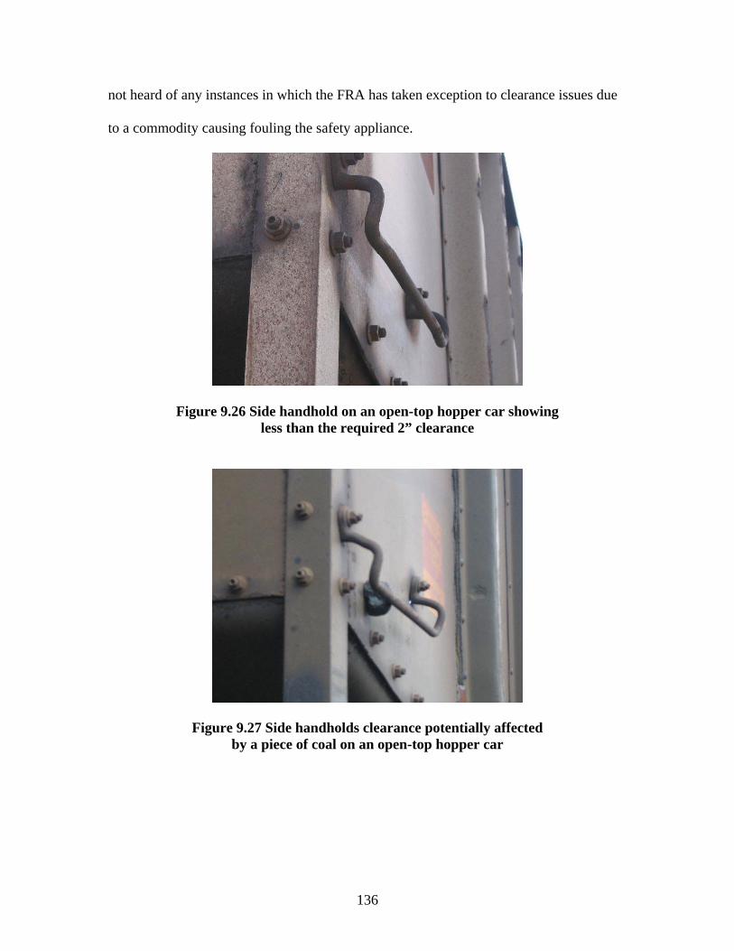
136
not heard of any instances in which the FRA has taken exception to clearance issues due
to a commodity causing fouling the safety appliance.
Figure 9.26 Side handhold on an open-top hopper car showing less than the required 2” clearance
Figure 9.27 Side handholds clearance potentially affected by a piece of coal on an open-top hopper car

137
9.7 Horizontal End Handholds
Horizontal end handholds are used for employees to hold onto the end of a railcar
while their foot rests on the sill step. As with side ladders the tread of the end ladder also
serves as an end handhold, thus these can serve as a location for footing when the ladder
is used.
Figure 9.28 View of both the AR and BR corners of the railcar showing the horizontal end handholds on open-top coal cars
9.7.1 Horizontal End Handhold Design Parameters (FRA 2004b)
Eight or more horizontal end handholds should be located on each railcar, with
four on each end (Figures 9.29 and 9.30). Horizontal end handholds should be made of
wrought iron or steel with a minimum diameter of 5/8”. The minimum clear length
should be 16”, preferably 24”. A 14” horizontal end handhold can be used if it is
impossible to mount a 16” one. One handhold should be located near each side on each
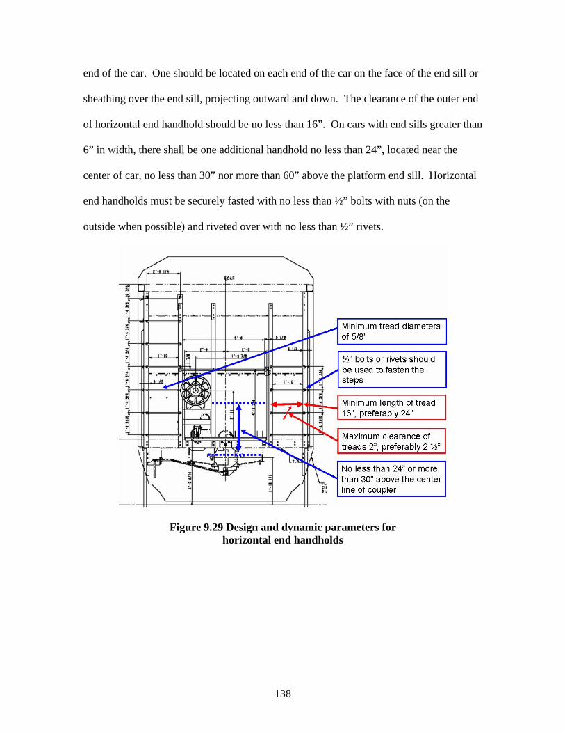
138
end of the car. One should be located on each end of the car on the face of the end sill or
sheathing over the end sill, projecting outward and down. The clearance of the outer end
of horizontal end handhold should be no less than 16”. On cars with end sills greater than
6” in width, there shall be one additional handhold no less than 24”, located near the
center of car, no less than 30” nor more than 60” above the platform end sill. Horizontal
end handholds must be securely fasted with no less than ½” bolts with nuts (on the
outside when possible) and riveted over with no less than ½” rivets.
Figure 9.29 Design and dynamic parameters for horizontal end handholds

139
Figure 9.30 Additional design and dynamic parameters for horizontal end handholds
9.7.2 Horizontal End Handhold Dynamic Parameters (FRA 2004b)
The minimum clearance should be 2”, preferably 2-1/2”. Horizontal end
handholds should be no more than 24”, nor more than 30” above the center line of
coupler except when the side handhold is a ladder tread. Clearance of outer end of
handhold shall be not more than 8” from end of car.
9.7.3 Horizontal End Handhold Machine Vision Image Considerations
Horizontal end handholds should be easily detected through a manner that is
similar to the one that recognizes ladder rung and side handholds.

140
9.8 Vertical End Handholds
Vertical end handholds are used for employees to hold the end of a railcar that has
a full width platform, most notably on boxcars.
9.8.1 Vertical End Handhold Design Parameters (FRA 2004b)
Two vertical end handholds should be located on each full width platform end-sill
car. Vertical end handholds should be made of wrought iron or steel with a minimum
diameter of 5/8”. The minimum clear length should be 18”, preferably 24”. Vertical end
handholds should be located opposite of the ladder, no more than 8” from the side of the
car. Vertical end handholds should be no more than 24”, or more than 30” above the
centerline of coupler. Vertical end handholds must be securely fastened with no less
than ½” bolts with nuts (on the outside when possible) and riveted over with no less than
½” rivets.
9.8.2 Vertical End Handhold Dynamic Parameters (FRA 2004b)
The minimum clearance should be 2”, preferably 2-1/2”.
9.8.3 Vertical End Handhold Machine Vision Image Considerations
The identification of vertical end handholds would require an approach different
than the ones used to identify ladder rungs and handholds due to the vertical alignment of
the handhold. Another difficulty may arise from the lack of multiple rungs to ease the
task of locating rungs as periodically spaced parallel lines.

141
9.9 Uncoupling Levers
Uncoupling levers are used by railroad employees to uncouple two railcars.
Employees actuate these while they are standing or walking alongside the railcar while
the train is in motion to uncouple railcars from one another.
Figure 9.31 Example of an uncoupling lever
9.9.1 Uncoupling Lever Design Parameters (FRA 2004b)
Two uncoupling levers should be located on each car using any efficient design.
If the car does not comply with plate B, handles should be no more than 6” from the side
of the car (Figure 9.32). If the car does comply with plate B, the handle should be no
more than 12”, preferably 9” from the side of car with a center lift arm no more than 7”
long. The center of eye at the end of lift arm shall not be more than 3-1/2” beyond the
center of eye of uncoupling pin of coupler. The minimum drop of the handle should be
12” and the maximum drop should be no more than 15” overall. Handles of the
“rocking” or “pushdown” variety shall not be more than 18” from the top of rail when the

142
cock has released the knuckle, and a suitable stop shall be provided to prevent the inside
arm from flying up in case of breakage.
Figure 9.32 design and dynamic parameters for the uncoupling lever
9.9.2 Uncoupling Lever Dynamic Parameters (FRA 2004b) The minimum clearance around the handle should be 2” and handles should
extend no more than 4” below the bottom of end sill.
9.9.3 Uncoupling Lever Machine Vision Image Considerations The uncoupling lever may prove to be the most challenging of all safety
appliances to identify using machine vision. The primary parameter that can be identified
using machine vision is the clearance around the lever. The primary difficulty in
identifying the uncoupling lever is the amount of “clutter” in the background which
produces many more edges than the uncoupling lever. Additionally, there is no angle

143
from which the uncoupling lever can be viewed that allows it to appear parallel or
perpendicular to any reference point in the image. Another difficulty in recognizing the
uncoupling lever is the wide variety of uncoupling lever designs. While all of these
uncoupling lever designs conform to CFR Part 231 the slight differences provide
challenges to a machine vision system.
9.10 End Ladder Clearance
End ladder clearance ensures that there is clearance for a railroad employee to
safely use the end ladder, brake step, or end platform without risk of coming in contact
with an adjacent railcar.
9.10.1 End Ladder Clearance Design Parameters (FRA 2004b)
The car is designed in a manner such that no portion of the car should be within
30” from the end of the car other than those specified (Figure 9.33). To be conservative,
these parameters will be considered dynamic parameters and will be addressed in the
following section.
9.10.2 End Ladder Clearance Dynamic Parameters (FRA 2004b) No part of the car above end sills should be within 30” from the side of car except
for the buffer block, brake shaft, brake wheel, or uncoupling lever shall extend to within
12” of a vertical plane parallel with the end of the car and passing through the inside face
of the coupler when closed.
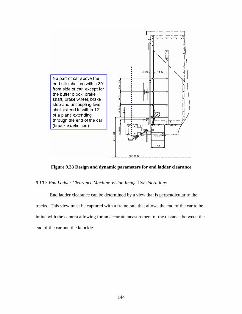
144
Figure 9.33 Design and dynamic parameters for end ladder clearance
9.10.3 End Ladder Clearance Machine Vision Image Considerations End ladder clearance can be determined by a view that is perpendicular to the
tracks. This view must be captured with a frame rate that allows the end of the car to be
inline with the camera allowing for an accurate measurement of the distance between the
end of the car and the knuckle.
145
CHAPTER 10: CONCLUSION
10.1 Summary
Since the installation of safety appliances was first required on railcars in 1893,
they have been visually inspected by humans. However, humans are limited in their
ability to rapidly and objectively assess many different items for extended periods and
avoid succumbing to fatigue. Railroad car inspections require railroad carmen to inspect
as many as 1,000 cars per shift, making the task monotonous and leaving room for error.
Technologies and inspection methods should be investigated that will increase both the
effectiveness and efficiency of safety appliance inspections. The positive effects of
adding additional technology to the car inspection process was shown through the
qualitative inspection cost model in Chapter 5.
The use of a machine-vision-enhanced inspection process could improve
performance and speed while possibly reducing cost. The capital cost of a machine
vision system will be higher than incremental addition to the labor force; however, the
cost per unit inspected may be lower, depending on the number of cars to be inspected at
a particular location. Additionally, the system would enable reallocation of labor to tasks
for which they are uniquely qualified, such as railcar repair. To take further advantage of
the system, some type of system memory should be incorporated because it would enable
better planning of railcar maintenance.
There are many examples of wayside rail vehicle health monitoring systems that
have been installed or are in the research and development stages. Examples of wayside

146
vehicle health monitoring systems are WILDs, TPDs, and the FactIS system which were
discussed in Chapter 6. These and other technologies can be linked to the InteRRIS
database which provides centralized information to the railroads and car owners allowing
for better management of railcar repair.
An additional benefit of a machine-vision-enhanced inspection system is that it
has the potential to partially alleviate congestion in rail yards. Because much of the
inspection process will occur along the line of road or at the entrance to a yard, railcars
may not need to occupy yard trackage for as long while they await and undergo
inspection. Instead, based on the outcome of the machine-vision results certain cars
requiring a closer look or minor repair could be promptly inspected and repaired, while
the remainder could be shunted directly to either their appropriate outbound track, or to a
major repair track. In conclusion, the prototype systems described here have the potential
to improve rail transportation safety and efficiency in several ways, including improving
the efficiency and effectiveness of the inspection process as well as improving rail yard
safety and productivity.
10.2 Future Research and Issues
Some repair issues may arise regarding how a defective safety appliance is dealt
with if it is detected between terminals where a repair shop is not located. This issue will
need to be addressed between the AAR and FRA before a machine vision system is
placed in the field with the capability of inspecting safety appliances.
As machine vision detection of safety appliances is adapted to other car and
appliance types, there are underlying difficulties that must be addressed. Some of these
147
issues are lighting needed for a machine vision system, the need to ensure safety
appliances are securely fastened, as well as how to store data on safety appliance defects.
Additional research should be undertaken to determine the magnitude of the
added capacity on receiving and departure tracks if additional technologies are added that
will increase the efficiency and effectiveness of car inspections. An economic analysis of
additional yard capacity gained from wayside inspection would aid in determining if such
an inspection system is cost justified.
There are a few modifications to the FRA database and data acquisition process
that would be helpful for future research. One modification would be the requirement for
inspectors to fill out narratives even if there is no fatality to allow for greater use of the
FRA database. Another suggestion would be the addition of codes that would point to
whether or not an accident or injury was caused by a defective safety appliance allowing
for better quantification of injuries associated with defective safety appliances.

148
REFERENCES
Adome (2006). Lens and Field of View Calculator. http://www.adome.net/catalog/information.php/info_id/10. [April 18, 2006].
Aldrich, M. (1992) Safety First Comes to the Railroads, 1910-1939. Railroad History,
Vol. 166, Spring 1992, pp 7-33. Aldrich, M. (1997). Safety First – Technology, Labor, and Business in the Building of
American Work Safety, The Johns Hopkins University Press, Baltimore, MD, pp 1-415.
Ameen, P. (2005-2006). Assistant Vice President, Technical Services. Association of
American Railroads (AAR). Personal Communications. [December 2005 - March 2006].
Association of American Railroads (AAR) (2003a). Car Repair Statistical Report – 2003,
Unpublished AAR Data. Association of American Railroads (AAR) (2003b). Railroad Facts - 2003 Edition,
Association of American Railroads, Washington, D.C. Association of American Railroads (AAR) (2004). Field Manual of the AAR Interchange
Rules, Association of American Railroads, Washington, D.C. Association of American Railroads (AAR) (2005). 2004 Analysis of Class I Railroads
Association of American Railroads, Washington, D.C. Association of American Railroads (AAR) (2006). Data Presented at the Technology
Driven Train Inspection Task Force Meeting in Washington, DC, February 7-8, 2006. Association of American Railroads, Washington, D.C.
Batchelor, B. (2005). Natural and Artificial Vision,
http://bruce.cs.cf.ac.uk/bruce/MV%20overview/TEXT.htm, [July 31, 2005]. Browder, W. (2005). Director of Operations, Association of American Railroads (AAR),
Personal Communication. [February 2005]. Carrulo, S. (2005). Safety Appliances / Railway Equipment Specialist, Federal Railroad
Administration (FRA). Unpublished Data, Personal Communication [June 2005]. Cielo, P. (1998). Optical Techniques for Industrial Inspection. Academic Press, Inc., San
Diego, CA, pp 1-606.
149
Dirnberger, J. (2006). Production Management Methods and the Development of a Quality of Sort Metric to Improve Classification Terminal Performance. Unpublished Masters Thesis. University of Illinois at Urbana-Champaign, Urbana, Illinois.
Federal Railroad Administration (FRA) (1981). Office of Research and Development.
Railroad Classification Yard Technology Manual Volume I: Yard Design Methods. SRI International, Menlo Park, CA.
Federal Railroad Administration (FRA) (2001). Office of Research and Development. An
Examination of Railroad Yard Worker Safety. Washington, D.C., http://www.fra.dot.gov/downloads/Research/ord0120.pdf, [August 2005].
Federal Railroad Administration (FRA) (2004a). Office of Safety. Motive Power and
Equipment Compliance Manual, Chapter 10: Railroad Safety Appliance Standards. Washington, D.C., http://www.fra.dot.gov/us/content/1248, [February 2004].
Federal Railroad Administration (FRA) (2004b). Office of Safety. Title 49 Code of
Federal Regulations (CFR), Railroad Mechanical Department Regulations, CFR Parts 210, 215, 216, 217, 218, 221, 223, 225, 229, 231, and 232. Railway Educational Bureau, Omaha, NE. [February 15, 2004].
Federal Railroad Administration (FRA) (2005). Office of Safety. Query Page.
http://safetydata.fra.dot.gov/OfficeofSafety/Query/Rrsys.pdf. [July 31, 2005]. Feigenbaum, A.V. (1983). Total Quality Control, McGraw Hill, New York, NY, pp 122-
124. Hart, J. M., Ahuja, N., Barkan, C.P.L., & Davis, D.D. (2004). A Machine Vision System
for Monitoring Railcar Health, Technology Digest, TD-008-2004, Association of American Railroads, Washington, D.C.
Hart, J. M. (2004-2006). Research Engineer, University of Illinois Urbana-Champaign.
Personal Communications [August 2004 - March 2006]. Hoyt, D. (2004). United States Region Mechanical Officer, Canadian National Railway.
Personal Communication. [November 18, 2004]. Interstate Commerce Commission (ICC) (1893). Seventh Annual Report of the Interstate
Commerce Commission, GPO, Washington D.C, 1893, pp 1-285. Interstate Commerce Commission (ICC) (1909). Twenty-Third Annual Report of the
Interstate Commerce Commission, GPO, Washington D.C, 1909, pp 1-338.

150
Interstate Commerce Commission (ICC) (1910). Twenty-Fourth Annual Report of the Interstate Commerce Commission. GPO, Washington, D.C. 1910. pp 1-358.
Kennedy, C. W. & Andrews, D. E. (1977). Inspection and Gaging. Industrial Press, Inc.,
New York, NY, pp 1-598. Lai, Y.C., Hart, J. M., Vemuru, P., Drapa, J., Ahuja, N., Barkan, C., Milhon, L., &
Stehly, M., (2005). Machine Vision Analysis of the Energy Efficiency of Intermodal Trains. In Proceedings of the 8th International Heavy Haul Conference "Safety, Environment, Productivity", (Cristiano G. Jorge, Coordinator - Technical Committee), Rio de Janiero, Brazil, June 14-16, 2005, International Heavy Haul Association, Virginia Beach, VA, pp. 387-394.
Luczak, M., (2005), Going by the Wayside, Railway Age, January 2005,
http://findarticles.com/p/articles/mi_m1215/is_1_206/ai_n11835921, [August 2005].
Medico-Actuarial Mortality Investigation (1913). The Effect of Occupation on Mortality.
The Association of Life Insurance Medical Directors and The Actuarial Society of America, New York, NY, pp. 16-19.
Morgan, R. & Anderson, G., (2003). TTCI Plays Detective: Transportation Technology
Center Inc.’s Intergraded Railway Remote Information Service, Railway Age, http://www.findarticles.com/p/articles/mi_m1215/is_2_204/ai_98265137, [August 2005].
Official Railway Equipment Register (ORER). (2005). The, R.E.R. Publishing
Corporation, New Jersey, Vol. 120, No. 3, p HC-15-16. Railway Educational Bureau (1998). Inbound Car Inspection Program, Training
Technologies, Omaha, NE. Shapiro, L.G. & Stockman, G.C. (2001). Computer Vision, Prentice Hall, Upper Saddle
River, NJ, pp 1-50. Smith, M. (2004-2006). Senior Mechanical Supervisor Central Illinois, Canadian
National Railway. Personal Communications. [November 18, 2004 – March 2006].
Switching Operations Fatality Analysis (SOFA) (2004). Findings and Recommendations
of the SOFA Working Group, August 2004 Update. http://www.fra.dot.gov/us/content/1506. [September 20, 2005].
Todorovic, S. (2005-2006). Postdoctoral Assistant, University of Illinois Computer
Vision and Robotics Laboratory. Personal Communications [May 2005 - March 2006].

151
United States House of Representatives (U.S. House) (2004). Office of Law Revision
Council. Chapter 203: Safety Appliances, Safety Appliance Statute, http://uscode.house.gov/, [April 1, 2006].
Wetzel, K. W. (1977). The Impact of Federal Safety Appliance Legislation Upon
Railroad Accidents. Doctoral Thesis. University of Illinois at Urbana-Champaign, Urbana, IL, pp 144-167.
White, J.H. (1993). The American Railroad Freight Car. The Johns Hopkins University
Press, Baltimore, MD, pp 517-518. White, J.H. (2005). The Strongest Handshake in the World. Invention and Technology,
Winter 2005, pp 51-54.

152
APPENDICES
APPENDIX A – Inbound Car Inspection Priorities Training Technologies, Inc. summarizes the defects that should be recognized as the
following:
1. Open missing or defective doors or door hangers (Non-SA)
2. Hand brake and hand brake chain defects that prevent proper hand brake operation
such as components that are not intact, bent, broken, or ineffective
3. A minimum clearance of 4 inches between the hand brake wheel and car body
4. Ladders, including ladder treads, that are bent or broken
5. A minimum clearance of 2 inches between the ladder treads and the car body
6. A minimum clearance of 2 inches or more around the uncoupling handle
7. Uncoupling handle to be 12 to 15 inches in length
8. Bent or broken uncoupling levers that prevent uncoupling mechanism to operate
9. Uncoupling levers on cars with cushioning devices that fail to telescope
10. Brake stapes that are damaged, loose, or not in place
11. Brake steps to be at least eight inches wide and the front of the step to be at least
four inches from the inside face of the coupler
12. Crossover steps to be at least 60 inches long
13. Sill steps to be securely fastened and to have adequate clearance
14. Sill steps to be less than 21 inches between treads
15. Safety railings on tank cars to be securely fastened and run the full length of the
tank, with proper clearance