Embed Size (px)
Citation preview
0
Improving the Engine Room of a Yacht
New technologies applicable in the engine room of a boat
and a case study of the potential of trigeneration system in
improving efficiency
Josep Castells Marsol
Degree Thesis for Bachelor of Engineering
Degree Programme in Energy and Enviromental Engineering
Vaasa (Finland), 2016
1
BACHELOR’S THESIS
Author: Josep Castells
Degree Program: Energy and Environmental Engineering
Supervisors: Charlotta Risku
Title: Improving the Engine Room of a Yacht
_________________________________________________________________________
Date 22-04-2016 Number of pages
_________________________________________________________________________
Abstract
The aim of this project is to improve the energy efficiency of a sailing yacht engine room by
reducing the inputs and maximizing the outputs and simultaneously striving to reduce the
weight. The document is structured in three sections; an introduction about the important
concepts and the case, a theoretical part with the technologies that are applicable in the
project and that could improve it and finally, an analysis and suggested improvements of the
system.
This project strives to explain the energy concepts, explore new ways of converting energy
resources into useful forms of energy and storing this energy that could be applied in the
engine room of a boat. Moreover, a system analysis is performed and used to design a
proposal for a new system and to identify if this new system uses the energy in a more
efficient way.
_________________________________________________________________________
Language: English Key words: engine room, boat, new technologies, efficiency
_________________________________________________________________________
2
Table of contents
1. Introduction ............................................................................................................... 1
1.1. General introduction .......................................................................................... 1
1.2. Baltic Yachts ..................................................................................................... 2
1.3. Objective ........................................................................................................... 2
2. Theoretical part ......................................................................................................... 3
2.1. Energy ............................................................................................................... 3
2.2. The First Law of Thermodynamics .................................................................... 3
2.2.1. Heat (sensible and latent) ........................................................................... 3
2.3. Transportation future challengers ....................................................................... 5
3. The engine room of a boat and technologies applicable in the engine room ................ 7
3.1. The engine room ................................................................................................ 7
3.2. Engine technologies ........................................................................................... 8
3.2.1. Internal combustion engines and the different cycles .................................. 9
3.2.2. External combustion engines (Stirling) ..................................................... 13
3.2.3. Chemical engines (fuel cells) .................................................................... 14
3.3. Energy storage technologies ............................................................................. 16
3.3.1. Electrochemical (batteries) ....................................................................... 16
3.3.2. Direct electric (ultra-capacitors and SMES) .............................................. 17
3.3.3. Direct thermal (sensible and latent heat) ................................................... 18
3.4. Reusing energy technologies ............................................................................ 19
3.4.1. Direct energy conversion (thermoelectric) ................................................ 19
3.4.2. Cogeneration technology (trigeneration) ................................................... 20
4. Case study ............................................................................................................... 23
4.1. Study system .................................................................................................... 23
4.1.1. Description ............................................................................................... 23
4.1.2. System analysis ........................................................................................ 25
4.2. Improvement.................................................................................................... 27
4.2.1. Equipment improvements ......................................................................... 27
3
4.2.2. Reusing energy improvements.................................................................. 28
4.3. Proposed system .............................................................................................. 30
4.3.1. The energy resource ................................................................................. 33
4.3.2. Systems of heat recuperation .................................................................... 33
4.3.3. Temperatures, flows and powers .............................................................. 34
4.4. Comparison between the systems ..................................................................... 35
4.4.1. kW/kg ...................................................................................................... 35
4.4.2. Efficiencies .............................................................................................. 35
5. Calculations ............................................................................................................. 36
5.1. Characteristics values of the systems ................................................................ 36
5.2. Calculations of the proposed system ................................................................ 37
5.2.1. Powers of the trigeneration system ........................................................... 37
5.2.2. Hot water flow in the refrigeration system ................................................ 38
5.2.3. Exit temperature in the heat recovery ....................................................... 38
5.2.4. Temperature in the exit of the absorption chiller ....................................... 39
5.3. Comparison between the systems ..................................................................... 40
5.3.1. kW/kg of the current system ..................................................................... 40
5.3.2. kW/kg of the proposed system.................................................................. 40
5.3.3. kW/kg of the extra weight of the new system ........................................... 41
5.3.4. Efficiencies of the systems ....................................................................... 42
6. Conclusion and personal reflection .......................................................................... 43
6.1. Conclusion ....................................................................................................... 43
6.2. Personal reflection ........................................................................................... 44
7. Literature references ................................................................................................ 45
8. Appendices ................................................................................................................. I
8.1. Equipment selection ............................................................................................ I
8.1.1. Exhaust gas heat exchanger selection .......................................................... I
8.1.2. Absorption chiller selection ...................................................................... III
8.2. Absorption chiller needs ............................................................................... VIII
8.3. Properties of the engine .................................................................................... XI
4
Table of tables
Table 1. Comparison of batteries types ................................................................................ 16
Table 2. Equipment of the engine room ............................................................................... 24
Table 3. Weigh variance ...................................................................................................... 41
Table 4. Comparison efficiencies (results) ........................................................................... 42
Table of figures
Figure 1. Substance changes of temperature .......................................................................... 4
Figure 2. Internal combustion (4 strokes) .............................................................................. 9
Figure 3. P-V Ideal Otto cycle ............................................................................................. 10
Figure 4. Efficiency of an otto cycle .................................................................................... 10
Figure 5. P-V Ideal Diesel cycle .......................................................................................... 11
Figure 6. Efficiency of a Diesel cycle ................................................................................. 11
Figure 7. Comparison between Otto (left) and miller cycle (Right) ..................................... 12
Figure 8. Stirling cycle ........................................................................................................ 13
Figure 9. Characteristics of different compact heat storage .................................................. 19
Figure 10. Thermolectric module ........................................................................................ 20
Figure 11. Sketch of CCHP that is adapted to an engine (heat process) ................................ 21
Figure 12. Sketch of CCHP that is adapted to an engine (cold PROCESS) .......................... 21
Figure 13. Sketch of the engine room .................................................................................. 23
Figure 14. Proposed trigeneration system (real) .................................................................. 30
Figure 15. Proposal for a trigeneration system (simplification) ............................................ 31
Figure 16. Temperatures in the heat recovery system (heat process) .................................... 34
Figure 17. Exhaust Gas Heat Exchanger Performance Table .................................................II
Figure 18. Catalogue Ibersolar ............................................................................................ IV
Figure 19. Catalogue Biobestenergy ..................................................................................... V
Figure 20. Catalogue Yazaki ............................................................................................... VI
Figure 21. Percentage thermal demand in a house (one year) ............................................... IX
Figure 22. Energy demand unifamiliar house (kWh/m2.year) .............................................. IX
1
1. Introduction
1.1. General introduction
“The environment is where we all meet; where all have a mutual interest; it is the one thing
all of us share.”-Lady Bird Johnson
“I think the environment should be put in the category of our national security. Defense of
our resources is just as important as defense abroad. Otherwise what is there to defend?”-
Robert Redford
Eliminating pollution problems is the 21st century goal. The responsibility to achieve this goal
is distributed. Companies should invest more to come up with new and more efficient
technologies. Consumers are also important; they need to become more responsible and
efficiency conscious, only in this way will the market be driven to change by consumer
demand. The engineers‟ responsibility is to be aware of both and try to implement their
demands into new projects. Saving the environment is best for companies and it is also best
for the world.
This project is a real project for the company Baltic Yachts and it is about applying
technologies in the engine room enabling a reduction of weight and an increase in efficiency.
All the equipment and the relation between them can be modified to achieve this goal.
The philosophy of the company is to build light, fast and strong yachts using the latest
technologies; consequently, they are also pioneers in research and development. The idea of
the project is to continue the company philosophy in developing or applying new ways to
improve the general efficiency and reduce the weight of the boat. Weight is the most
important parameter but efficiency is also very important in a light boat because the energy
resources are limited. This project is only the first part of a larger project aiming at improving
the system in the totality of the boat.
This thesis consists basically of three important parts. Firstly, some general concepts to the
project such as the concept of energy and the first law of thermodynamics are introduced. The
second part discusses possible technologies applicable to the engine room. These
2
technologies are focus on improving equipment or reusing lost energy. This part will be used
to determine the new system, the equipment and the system itself. The first two parts build
up the knowledge needed in order to analyze the system in section three and to design the
proposal for a new system.
1.2. Baltic Yachts
The company Baltic Yachts was founded in 1973. This company is located in Ostrobothnia
on the west coast of Finland, where a professional team is working to make the customers
sailing yacht dreams come true. The philosophy of the company is to build light and fast
yachts with all the latest technology.
Originally, Baltic Yachts was situated in Bosund (Ostrobonia region) in Western Finland.
The company builds high tech performance sailing yachts using state of the art materials and
technology. The first boat completely made of carbon fiber was manufactured in 1995 but the
company has been using carbon fiber since 1979. In 2002 the first boat more than 100 feet
long was sailing. These big boats are the reason why the company moved part of the
functions to Jakobstad. Today, the company makes boats that can be up to 200 feet with the
latest technologies.
1.3. Objective
The objective of this project is defined by the company and it consists of finding a way to
improve the engine room design through simultaneously reducing weight and increasing
efficiency. In other words, a new system which increases the efficiency with the lightest
possible equipment has to be developed. Consequently, higher power per kilogram value has
to be achieved.
3
2. Theoretical part
2.1. Energy
The word “energy” appeared in the 16th century. It originates from the French word énergie
or late Latin from Greek energeia, from en-„in, within‟ + ergon „work‟. This word has more
definitions that are very far from the original meaning, it is used in economy and other topics.
However, the meaning that is of interest to us is the one used in physics. Defined by the
Oxford dictionary with the following words: “The property of matter and radiation which is
manifest as a capacity to perform work (such as causing motion or the interaction of
molecules): a collision in which no energy is transferred.”
The 1st law of thermodynamics says that energy cannot be created or destroyed, only
transformed. Therefore, the only way to generate energy is to take this energy from an energy
resource. In the transportation field the energy resource is the fuel.
2.2. The First Law of Thermodynamics
Thermodynamics is the physics branch which studies the energy transfer process. The first
postulate of thermodynamics says that when objects with different temperatures are put
together, the temperatures tend to equalize. This phenomenon happens because the hotter
object gives energy to the cooler one, causing heat transfer.
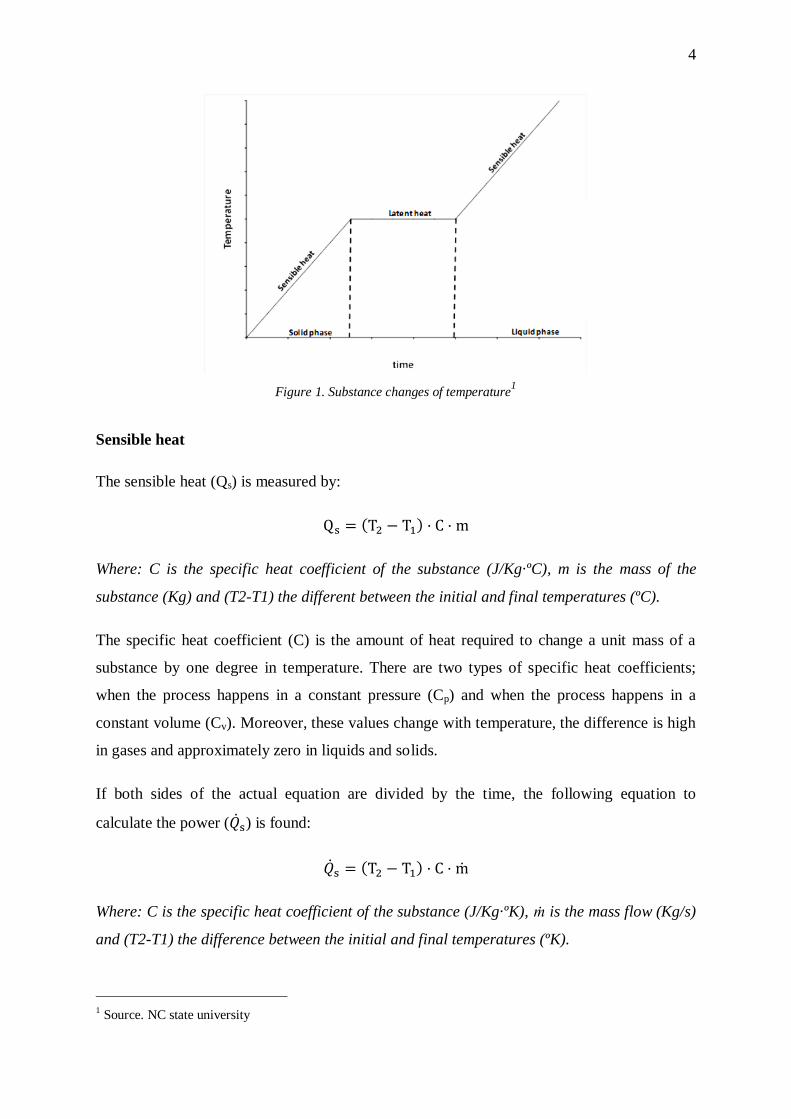
2.2.1. Heat (sensible and latent)
Heat (Q) is defined as the kinetic energy of the total atoms and molecules of a substance. This
concept is used to refer to the thermal energy transfer. When some substances receive heat,
two things can happen: the state of the substance does not change (sensible heat) or it
experiences a change of state (latent heat). The formulas for these situations are completely
different.
4
Figure 1. Substance changes of temperature1
Sensible heat
The sensible heat (Qs) is measured by:
( )
Where: C is the specific heat coefficient of the substance (J/Kg·ºC), m is the mass of the
substance (Kg) and (T2-T1) the different between the initial and final temperatures (ºC).
The specific heat coefficient (C) is the amount of heat required to change a unit mass of a
substance by one degree in temperature. There are two types of specific heat coefficients;
when the process happens in a constant pressure (Cp) and when the process happens in a
constant volume (Cv). Moreover, these values change with temperature, the difference is high
in gases and approximately zero in liquids and solids.
If both sides of the actual equation are divided by the time, the following equation to
calculate the power ( ) is found:
( )
Where: C is the specific heat coefficient of the substance (J/Kg·ºK), ṁ is the mass flow (Kg/s)
and (T2-T1) the difference between the initial and final temperatures (ºK).
1 Source. NC state university
5
Latent heat
The latent heat (Ql) is measured by:
Where: m is the mass of material undergoing a phase change (kg) and l is the latent heat of
the phase change (J/kg).
The latent heat of a specific substance changes depending on the phase change.
If both sides of the actual equation are divided by the time, the following equation to
calculate the power ( ) is founded:
Where: m is the mass flow of material undergoing a phase change (kg/s) and l is the latent
heat of the phase change (J/kg).
2.3. Transportation future challengers
Energy consumption has increased since the first industrial revolution in 1840 and it is
expected to continue growing over the next 50 years. However, the situation is very different
now because developed countries have reduced the tax on demand and other underdeveloped
countries like China and India have started to play an important role in energy consumption.
These countries have low concern about climate change and they have a high consumption of
coal. On the other hand, renewable energy has improved a lot and it has had a high
acceptance rate by consumers.
In the transportation sector there has been a large increase. This sector is based on oil
products, and-hence produces a large amount of CO2 and other air pollutants. In 2002, the
transportation sector accounted for 21%2 of all CO2 emissions worldwide. Therefore, the
energy system needs to change to renewable energy with greater speed. The transportation
2 Source. Kreith F. and D. Yogi Goswami. (2008).Energy conversion. Broken Sound
Parkway NW. Taylor and Francis group. Print

6
sector is one of the areas where reducing the GHG emissions has to be prioritized because the
actual system is not sustainable.
However, to supply the increase of consumption it is necessary to use fossil fuels in the next
years. The reason is that all the changes have to be progressives; the procedure is increase the
efficiency rate at the same time changing to renewable resources.

7
3. The engine room of a boat and technologies applicable in the
engine room
3.1. The engine room
The engine room of a boat is the space in a boat where it is possible to find almost all the
technological equipment which generates the power for movement and other useful outputs
like cold air for the air-conditioning or hot water. One reason for concentrating all this
equipment like compressors, engine, generators, and pumps in one place is striving to insulate
the noise, heat and vibrations that this equipment produces.
Space is limited and all the equipment has a specific position that reduces the space. All the
equipment and the connections between them are designed carefully to achieve this purpose.
Moreover, a ventilation system is needed to reduce the high temperatures generated in a room
with a lot of machinery.
The engine room has to supply enough electricity, hot water and mechanical power to cover
the needs of the boat. For this purpose, there is different essential to achieve this goal. The
most important elements that are common in all engines rooms are the following ones:
The engine is the most important element in the engine room and it transforms an
energy resource into an useful form of energy. The main task of the engine is creating
the propulsion power moving the boat. The most common type of engine in this
application is internal combustion engines because diesel and petrol are the fuels
which dominate the current transportations market. However, new technologies are
continuously developed and merging the market.
Generator (mechanical to electrical power) transforms mechanical to electrical
power is called alternator. This element enable using the mechanical power the engine
produces generating electricity to cover the power demand.
Generators (fuel to electrical power) is a combination between the engine and the
alternator and it is used to supply the electricity demand instead of the engine and the
generators that are explained before. The generator which generates electricity from
8
fuel is used when the engine is in mode off or when the electricity power demand is
higher than the power produced by the engine and the alternator.
Electrical batteries have two different purposes. The first is starting the engine when
some initial energy is needed and the second is to compensate the high and low levels
of production to give a constant supply.
Air-conditioning machine uses electrical power to produces cold water for the air-
conditioning system of the boat. However, it can be replaced by an absorption chiller
if the energy source is hot water instead of electrical power.
Water heater and hot water accumulator. These two elements usually work
together. The water heater increases the temperature of the water and then the hot
water is kept in the accumulator for later use. Storage of hot water is necessary
because the time to warm the water is usually longer than the time to consume it.
Circulation pumps are part of the refrigeration system. Its function is moving the
water to reduce high temperatures in the equipment. However, there are other pumps
that move the potable water inside the boat.
Water intake system is a complex system required to take in the seawater used in the
refrigeration system avoiding bubbles and solid impurities to.
There are some relevant technologies that are implemented or could be applied in the engine
room of a yacht. The most important technologies to understand and improve the engine
room are focused in the engine, storage systems and reusing energy technologies.
3.2. Engine technologies
The engine is the most important part in the engine room because it produces all the power of
the system. This power comes from an energy resource (fuel) and the engine transforms this
fuel into useful power such as mechanical or electrical. However, there are losses in this
process. In boats the engine power is used to move the boat or to produce electricity in case
there is not electrical generator.
9
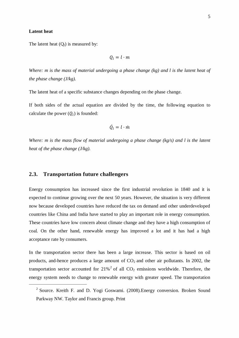
3.2.1. Internal combustion engines and the different cycles
The most common types of combustion engines are the Otto engine (spark ignition) and the
Diesel engine which uses compression to ignite the combustible. The rotary engine called
Wankel is another technology that can be found in the vehicle industry but this is not
currently used in boats.
Figure 2. Internal combustion (4 strokes)
For understanding how the engines work and to study some parameters like the compression
ratio which governs the thermal efficiency an idealization is needed. The main idea is to take
the following assumptions which make the process more understandable:
1. The working substance is air.
2. The air is assumed to behave as an ideal gas with constant specific heats.
3. Heat is added to the cycle from an external source.
4. Expansion and compression processes are isentropic.
Intake
stroke
Compression
stroke
Power
stroke
Exhaust
stroke
10
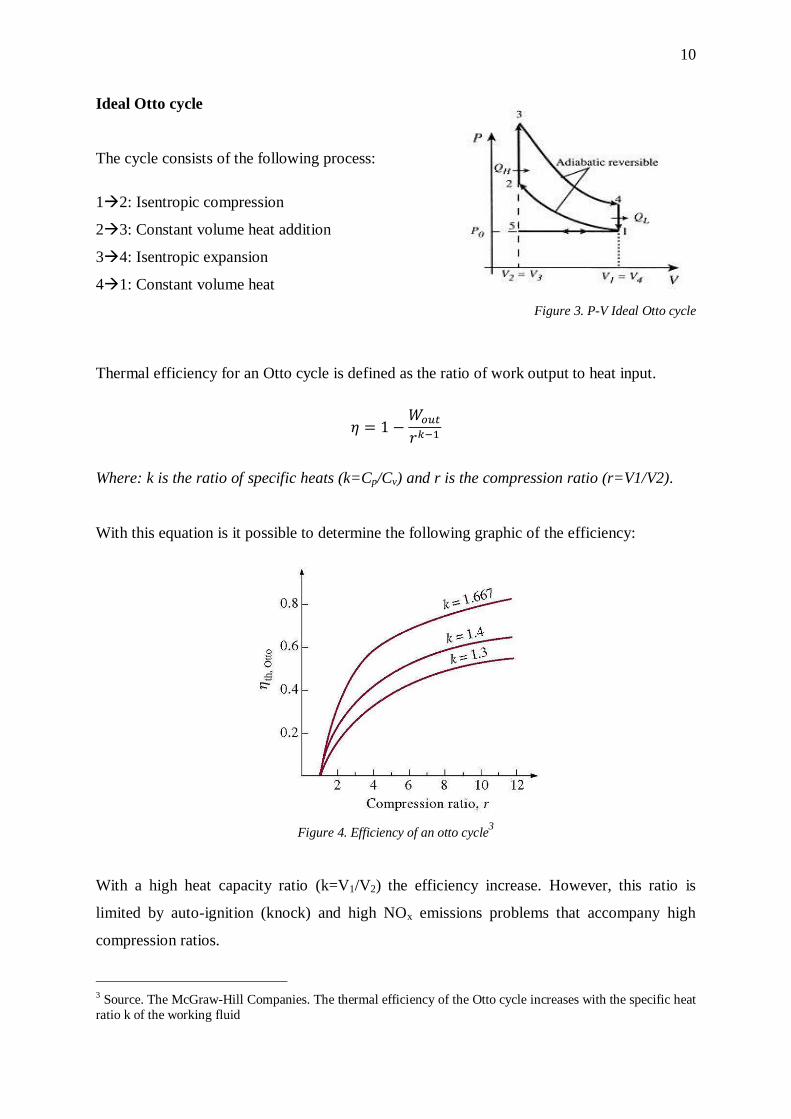
Ideal Otto cycle
The cycle consists of the following process:
12: Isentropic compression
23: Constant volume heat addition
34: Isentropic expansion
41: Constant volume heat
Figure 3. P-V Ideal Otto cycle
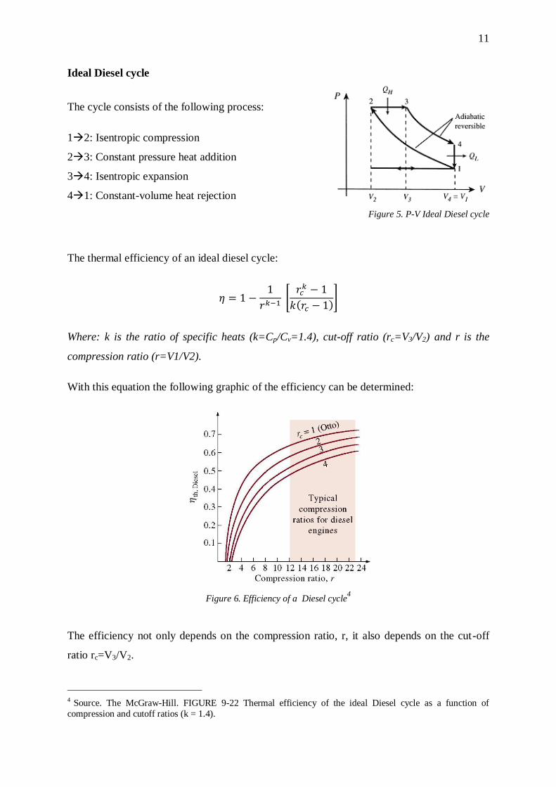
Thermal efficiency for an Otto cycle is defined as the ratio of work output to heat input.
Where: k is the ratio of specific heats (k=Cp/Cv) and r is the compression ratio (r=V1/V2).
With this equation is it possible to determine the following graphic of the efficiency:
Figure 4. Efficiency of an otto cycle3
With a high heat capacity ratio (k=V1/V2) the efficiency increase. However, this ratio is
limited by auto-ignition (knock) and high NOx emissions problems that accompany high
compression ratios.
3 Source. The McGraw-Hill Companies. The thermal efficiency of the Otto cycle increases with the specific heat
ratio k of the working fluid
11
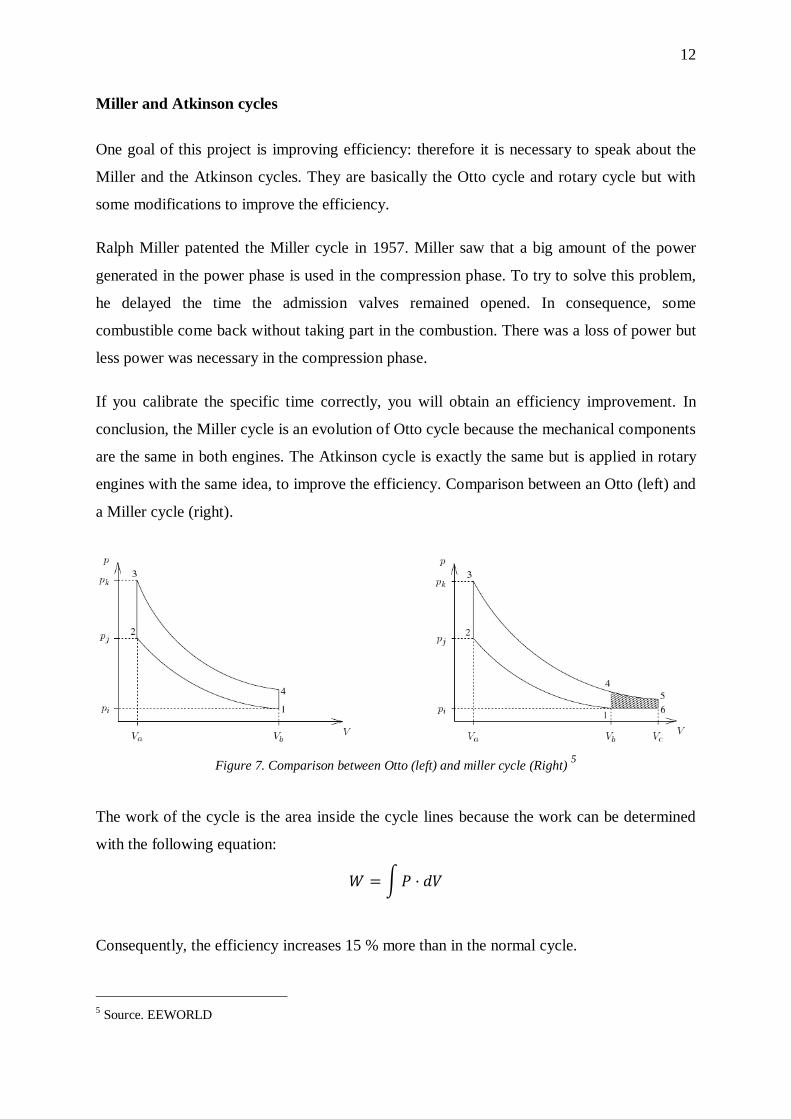
Ideal Diesel cycle
The cycle consists of the following process:
12: Isentropic compression
23: Constant pressure heat addition
34: Isentropic expansion
41: Constant-volume heat rejection
Figure 5. P-V Ideal Diesel cycle
The thermal efficiency of an ideal diesel cycle:
[
( )]
Where: k is the ratio of specific heats (k=Cp/Cv=1.4), cut-off ratio (rc=V3/V2) and r is the
compression ratio (r=V1/V2).
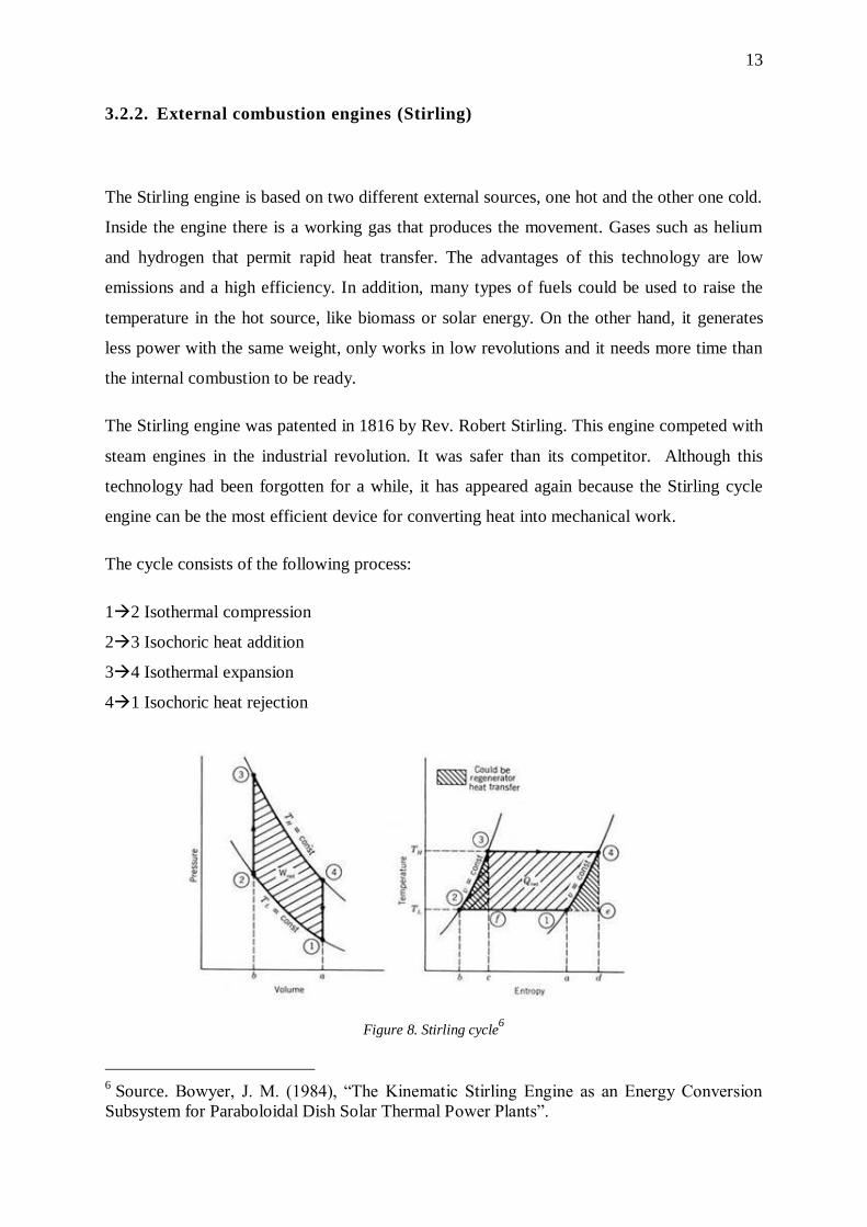
With this equation the following graphic of the efficiency can be determined:
Figure 6. Efficiency of a Diesel cycle4
The efficiency not only depends on the compression ratio, r, it also depends on the cut-off
ratio rc=V3/V2.
4 Source. The McGraw-Hill. FIGURE 9-22 Thermal efficiency of the ideal Diesel cycle as a function of
compression and cutoff ratios (k = 1.4).
12
Miller and Atkinson cycles
One goal of this project is improving efficiency: therefore it is necessary to speak about the
Miller and the Atkinson cycles. They are basically the Otto cycle and rotary cycle but with
some modifications to improve the efficiency.
Ralph Miller patented the Miller cycle in 1957. Miller saw that a big amount of the power
generated in the power phase is used in the compression phase. To try to solve this problem,
he delayed the time the admission valves remained opened. In consequence, some
combustible come back without taking part in the combustion. There was a loss of power but
less power was necessary in the compression phase.
If you calibrate the specific time correctly, you will obtain an efficiency improvement. In
conclusion, the Miller cycle is an evolution of Otto cycle because the mechanical components
are the same in both engines. The Atkinson cycle is exactly the same but is applied in rotary
engines with the same idea, to improve the efficiency. Comparison between an Otto (left) and
a Miller cycle (right).
Figure 7. Comparison between Otto (left) and miller cycle (Right) 5
The work of the cycle is the area inside the cycle lines because the work can be determined
with the following equation:
∫
Consequently, the efficiency increases 15 % more than in the normal cycle.
5 Source. EEWORLD
13
3.2.2. External combustion engines (Stirling)
The Stirling engine is based on two different external sources, one hot and the other one cold.
Inside the engine there is a working gas that produces the movement. Gases such as helium
and hydrogen that permit rapid heat transfer. The advantages of this technology are low
emissions and a high efficiency. In addition, many types of fuels could be used to raise the
temperature in the hot source, like biomass or solar energy. On the other hand, it generates
less power with the same weight, only works in low revolutions and it needs more time than
the internal combustion to be ready.
The Stirling engine was patented in 1816 by Rev. Robert Stirling. This engine competed with
steam engines in the industrial revolution. It was safer than its competitor. Although this
technology had been forgotten for a while, it has appeared again because the Stirling cycle
engine can be the most efficient device for converting heat into mechanical work.
The cycle consists of the following process:
12 Isothermal compression
23 Isochoric heat addition
34 Isothermal expansion
41 Isochoric heat rejection
Figure 8. Stirling cycle6
6 Source. Bowyer, J. M. (1984), “The Kinematic Stirling Engine as an Energy Conversion
Subsystem for Paraboloidal Dish Solar Thermal Power Plants”.
14
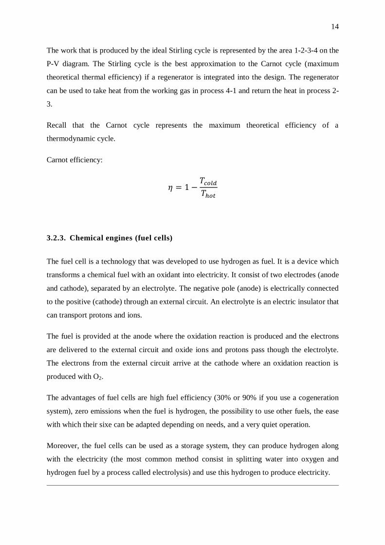
The work that is produced by the ideal Stirling cycle is represented by the area 1-2-3-4 on the
P-V diagram. The Stirling cycle is the best approximation to the Carnot cycle (maximum
theoretical thermal efficiency) if a regenerator is integrated into the design. The regenerator
can be used to take heat from the working gas in process 4-1 and return the heat in process 2-
3.
Recall that the Carnot cycle represents the maximum theoretical efficiency of a
thermodynamic cycle.
Carnot efficiency:
3.2.3. Chemical engines (fuel cells)
The fuel cell is a technology that was developed to use hydrogen as fuel. It is a device which
transforms a chemical fuel with an oxidant into electricity. It consist of two electrodes (anode
and cathode), separated by an electrolyte. The negative pole (anode) is electrically connected
to the positive (cathode) through an external circuit. An electrolyte is an electric insulator that
can transport protons and ions.
The fuel is provided at the anode where the oxidation reaction is produced and the electrons
are delivered to the external circuit and oxide ions and protons pass though the electrolyte.
The electrons from the external circuit arrive at the cathode where an oxidation reaction is
produced with O2.
The advantages of fuel cells are high fuel efficiency (30% or 90% if you use a cogeneration
system), zero emissions when the fuel is hydrogen, the possibility to use other fuels, the ease
with which their sixe can be adapted depending on needs, and a very quiet operation.
Moreover, the fuel cells can be used as a storage system, they can produce hydrogen along
with the electricity (the most common method consist in splitting water into oxygen and
hydrogen fuel by a process called electrolysis) and use this hydrogen to produce electricity.
15
There are lots of types of fuel cells, but the most common ones are the following types:
Polymer electrolyte membrane fuel cells (PEMFC) use a Proton Exchange
Membrane Fuel Cells as an electrolyte and porous carbon electrodes containing
platinum. This platinum works as a catalyst too. The temperature is around 60-80ºC
and the efficiency is between 40% and 50%. Platinum is extremely sensitive to carbon
monoxide, making it necessary to employ an additional reactor to reduce the CO in
the fuel gas if the hydrogen comes from a hydrocarbon fuel. Consequently, the
installation is much more expensive and the hydrogen fuel has to be more pure (CO
concentration < 100 ppm (Araujo, 2012)).
Direct methanol fuel cells (DMFC) are similar to PEMFC with one difference; the
catalyst is the anode itself which obtain hydrogen from liquid methanol. The
efficiency is around 40% and the working temperature between 50ºC and 100ºC.
However, there is a very important problem called fuel permeability. This is a
chemical short-circuit or crossover from the anode to the cathode so the generation of
electricity does not work.
Alkaline fuel cells (AFC). In this type of fuel cells the electrolyte is made with an
alkaline dissolution, the conduction is produced by OH- ions. The working
temperature is between 100ºC and 250ºC and the efficiency is around 70%. The only
problem is the formation of alkali carbonates but this is solved by using pure
hydrogen, H2.
Phosphoric acid fuel cells (PAFC) use concentrated phosphoric acid as an
electrolyte, which conducts the protons. The electrodes use platinum as a catalyst. The
working temperature is around 200ºC and the efficiency is 40% to 80% if you use a
cogeneration system.
Molten carbonate fuel cells (MCFC) have a combination of alkaline carbons which
are fixed in a ceramic matrix (LiAlO2) as an electrolyte. The working temperature is
higher than in the previous ones, around 700ºC. The anode electrode is made with Ni
and the cathode with NiO. The nickel in the anode works like a catalyst and reduces
the price compared to the platinum. The common value for the efficiency is 60% and
it could be 85% with cogeneration. The main problems are the shorter life span and
the formation of water in the anode which dilutes the fuel.
Solid oxide fuel cells (SOFC) are based on the capacity of certain ceramic oxides to
transport ions and they use this ceramic as electrolyte too. SOFC remove the need for
a metal catalyst and have efficiencies between 60% and 85%. However, they have an
important problem with high temperatures: 600-1000ºC.
16
3.3. Energy storage technologies
Storage technologies play an important role in the energy sector because it is easier to
produce electricity in one place like a nuclear generation plant and then use this energy for
everything, than to produce electricity in every single engine in, for example, the field of
transportation.
Another reason is the stabilization in a renewable technology or cogeneration energy system,
where the production and the demand do not go together. The stabilization of the system is
always necessary if the system is not constant, the production or demand are not fixed. For
example, in a cogeneration system the energy has to be stored for a later use.
There are lots of technologies applied for storing energy but the ones that could be used in a
boat are presented below.
3.3.1. Electrochemical (batteries)
Electrochemical batteries work by generating different polarity loads at the ends of a
conductive thread, causing electrons to move. There are two plates of different materials
which are connected to each other with conductive material and between them there is an
aqueous environment with a chemical component which reacts when electrons are moved.
When the polarity of the circuit is changed the reactions happen in the other direction
(recharge).
There are lots of different types of batteries; lead-acid, lithium-ion, nickel-cadmium, nickel-
metal hydride, sodium-sulfur, zebra and flow batteries, vanadium redox, polysulfide bromide,
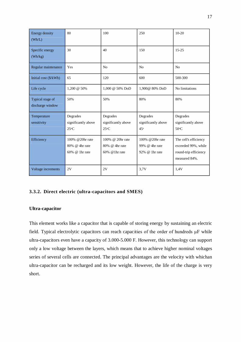
zinc-bromin, electrolytic hydrogen (used in fuel cells). The most common ones are
represented with their properties in the following table:
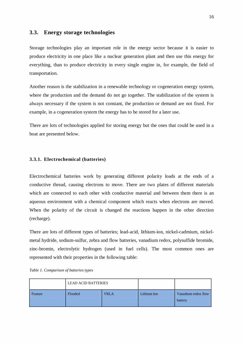
Table 1. Comparison of batteries types
LEAD ACID BATTERIES
Feature Flooded VRLA Lithium Ion Vanadium redox flow
battery
17
Energy density
(Wh/L)
80 100 250 10-20
Specific energy
(Wh/kg)
30 40 150 15-25
Regular maintenance Yes No No No
Initial cost ($/kWh) 65 120 600 500-300
Life cycle 1,200 @ 50% 1,000 @ 50% DoD 1,900@ 80% DoD No limitations
Typical stage of
discharge window
50% 50% 80% 80%
Temperature
sensitivity
Degrades
significantly above
25ᵒC
Degrades
significantly above
25ᵒC
Degrades
significantly above
45ᵒ
Degrades
significantly above
50ᵒC
Efficiency 100% @20hr rate
80% @ 4hr rate
60% @ 1hr rate
100% @ 20hr rate
80% @ 4hr rate
60% @1hr rate
100% @20hr rate
99% @ 4hr rate
92% @ 1hr rate
The cell's efficiency
exceeded 99%, while
round-trip efficiency
measured 84%.
Voltage increments 2V 2V 3,7V 1,4V
3.3.2. Direct electric (ultra-capacitors and SMES)
Ultra-capacitor
This element works like a capacitor that is capable of storing energy by sustaining an electric
field. Typical electrolytic capacitors can reach capacities of the order of hundreds μF while
ultra-capacitors even have a capacity of 3.000-5.000 F. However, this technology can support
only a low voltage between the layers, which means that to achieve higher nominal voltages
series of several cells are connected. The principal advantages are the velocity with whichan
ultra-capacitor can be recharged and its low weight. However, the life of the charge is very
short.
18
SMES (Superconducting magnetic)
This is a system that permits storing the energy in a magnetic field which is created by the
flow of direct current in a superconducting coil. For applications to transportation it is not
very useful because it only behaves well at low charge discharge rates, although the
efficiency is very high with 97%- 98% values.
3.3.3. Direct thermal (sensible and latent heat)
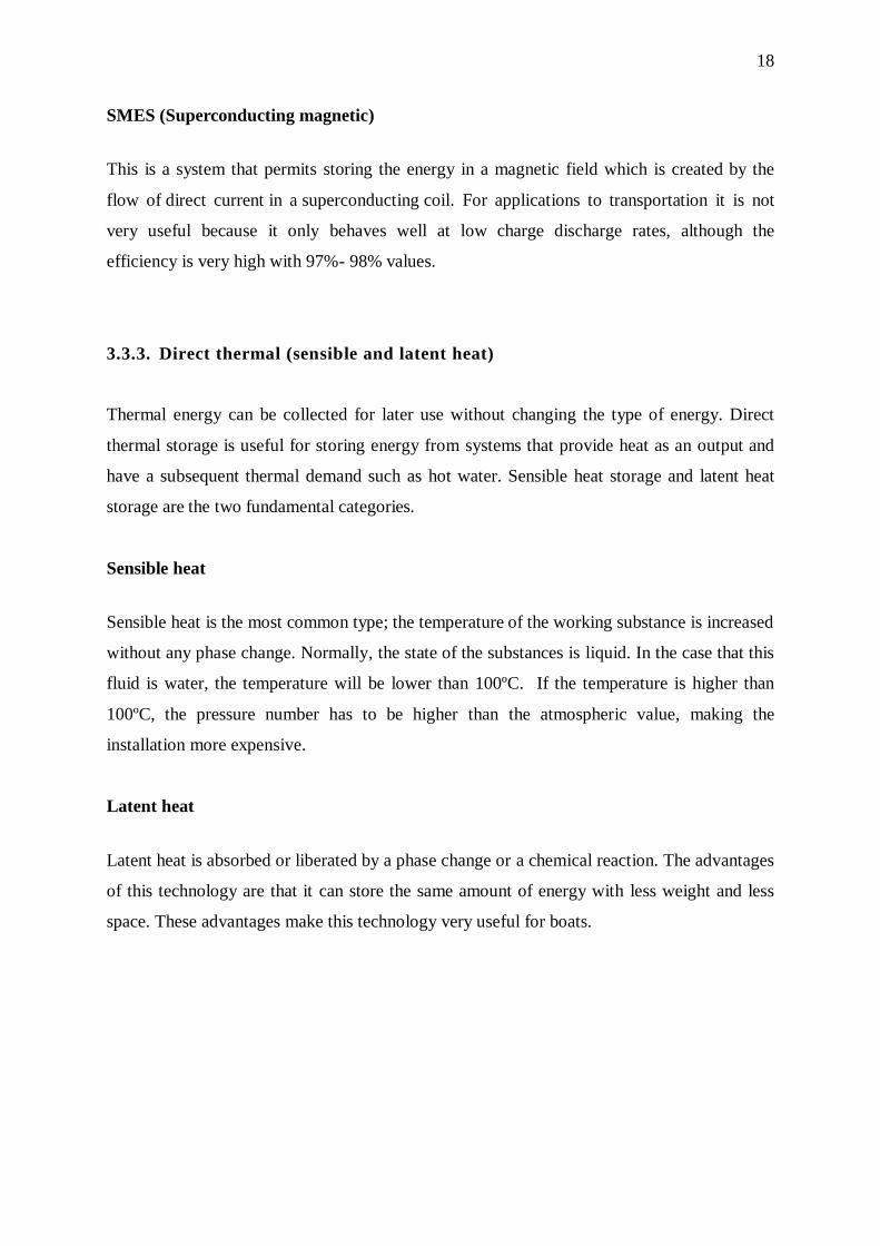
Thermal energy can be collected for later use without changing the type of energy. Direct
thermal storage is useful for storing energy from systems that provide heat as an output and
have a subsequent thermal demand such as hot water. Sensible heat storage and latent heat
storage are the two fundamental categories.
Sensible heat
Sensible heat is the most common type; the temperature of the working substance is increased
without any phase change. Normally, the state of the substances is liquid. In the case that this
fluid is water, the temperature will be lower than 100ºC. If the temperature is higher than
100ºC, the pressure number has to be higher than the atmospheric value, making the
installation more expensive.
Latent heat
Latent heat is absorbed or liberated by a phase change or a chemical reaction. The advantages
of this technology are that it can store the same amount of energy with less weight and less
space. These advantages make this technology very useful for boats.
19
Figure 9. Characteristics of different compact heat storage7
3.4. Reusing energy technologies
Technologies that reuse energy transform energy losses into useful energy. The most
common are thermal losses so these technologies try to use them for another use. For
example by converting the thermal to electrical energy or using the thermal energy for
another useful goal.
3.4.1. Direct energy conversion (thermoelectric)
Direct ways to transform energy outputs into other useful income energy are very helpful to
improve the system. It is possible to make an important efficiency improvement and to
reduce the space making the system less complex compared to other methods.
The advances in materials science during the 1940s and 1950s and the consequents
discoveries in the field of semiconductors made possible the fabrication of thermoelectric
generators. These are small and have high reliability, long life and do not produce vibrations.
The working temperature range is very large, 200K to 1300K. However, because of the price
and the low efficiency (less than 10%) this technology has taken a backseat until now,
whereas some industries like the automation industry are trying to research it. The first results
are appearing, for example the ATEG, a device that converts some of the waste heat of an
internal combustion engine into electrical power.
7 Source. ECN (Energy storage Centre in the Netherlands)
20
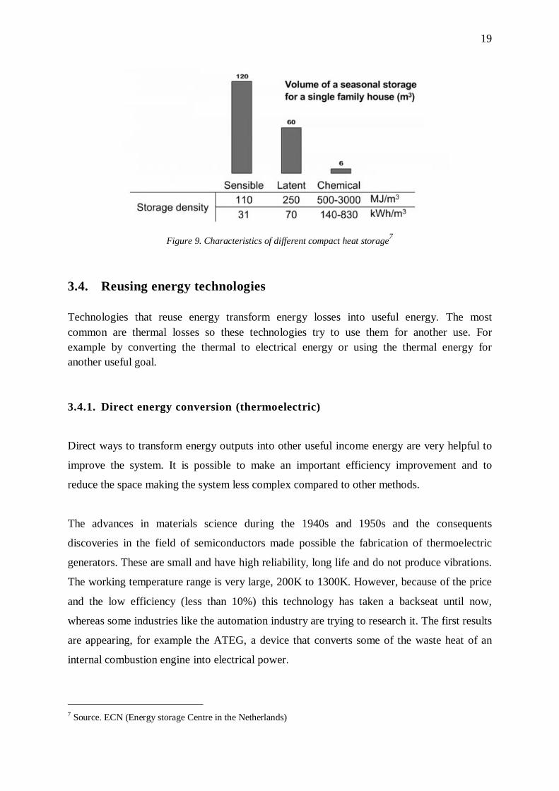
The basic device is a thermoelectric module which consists of several p- and n- type
materials connected in parallel electrically and thermally, and bonded with ceramic plates on
the sides. The properties such as efficiency change a lot depending on the size, shape and
number of thermoelectric couples.
Figure 10. Thermolectric module8
3.4.2. Cogeneration technology (trigeneration)
Cogeneration technology CHP (Combined Heat and Power) appeared in the nineteenth
century with the industrial revolution. It put the heat power that was lost in steam engines to
other uses. The technology has changed a lot since the industrial revolution but the efficiency
of engines continues to be very low, less than 40%. Consequently, using the losses is
necessary to increase the useful energy.
The main change in cogeneration technology is the way has adapted to small engines and
systems. Micro-cogeneration is one of the best ways to improve the general efficiency in a
system such as a boat.
Trigeneration (CCHP)
Trigeneration technology is a specific form of cogeneration technology that can be used for
heating and cooling too. This is very advantageous in hot places, where air-conditioning is
necessary during the summer.
8 Source. Module (Scientific and Production firm)
21
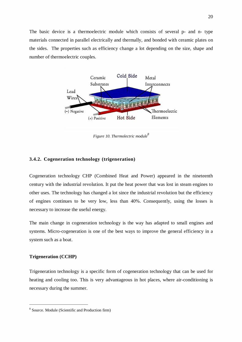
Heat process
Figure 11. Sketch of CCHP that is adapted to an engine (heat process)
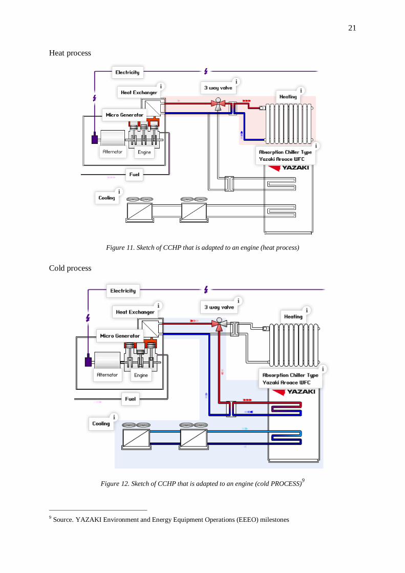
Cold process
Figure 12. Sketch of CCHP that is adapted to an engine (cold PROCESS)9
9 Source. YAZAKI Environment and Energy Equipment Operations (EEEO) milestones
22
A trigeneration system has some particular parts which are shown in the following example
of a trigeneration installation that is installed in an engine:
Recovery energy losses. The engine produces useful power from fuel and air but
generates some thermal losses. To reuse the temperature for the engine there are the
refrigeration system that takes the heat out of the inside of the engine. Moreover, the
escape of gases and oil generate thermal losses too. When there is a generator
(alternator), this is another hot point in the system and can also be used to raise the
temperature.
Three way valve has a main function in the CCHP system because it allows selecting
the hot water direction depending on needs, increasing or reducing the temperature of
the boat.
Storage tank is installed at the beginning of the central heating installation.
Absorption chiller is the most complex part in the trigeneration technology and
consists of a refrigerator that uses a heat source to produce cold.
Fan cool units are the last step in the refrigeration cycle and it is the machine that
provides a cool air flow from the chilled water.
23
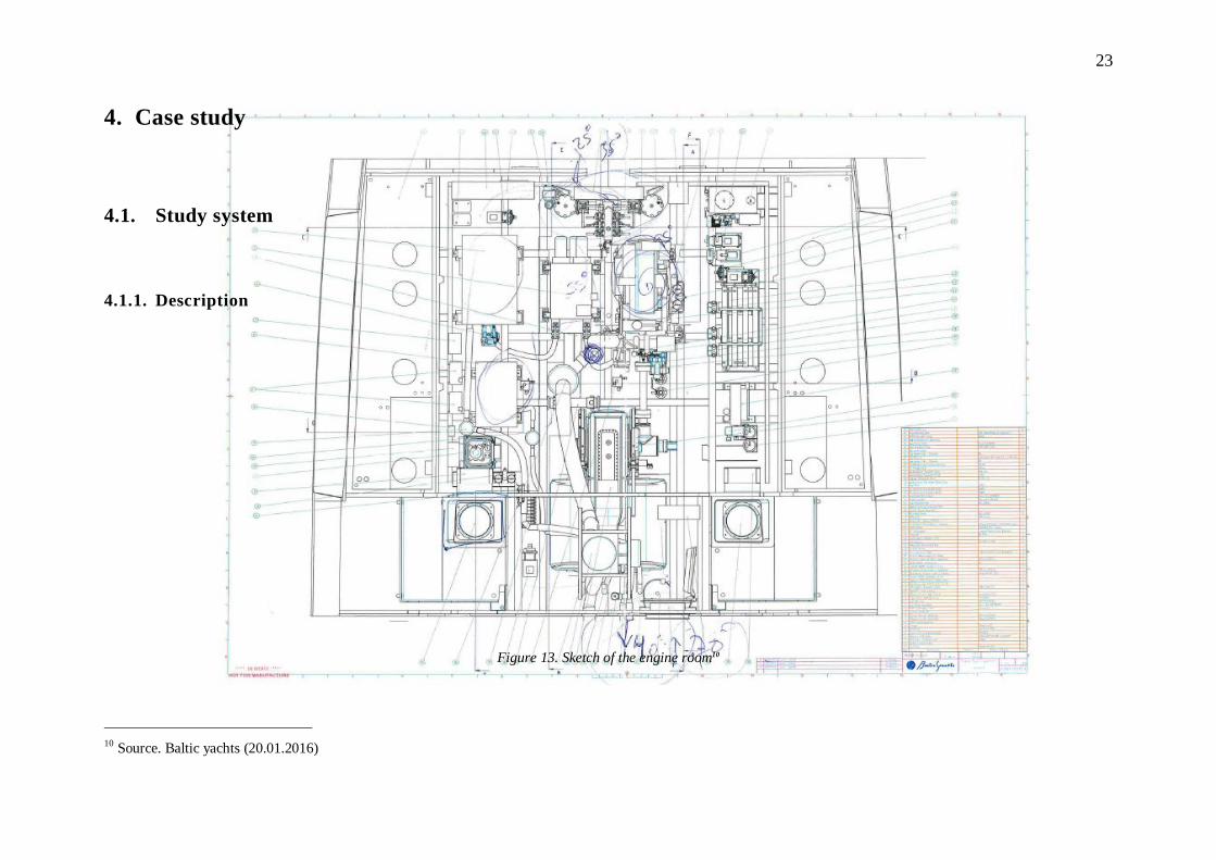
4. Case study
4.1. Study system
4.1.1. Description
Figure 13. Sketch of the engine room10
10 Source. Baltic yachts (20.01.2016)
24
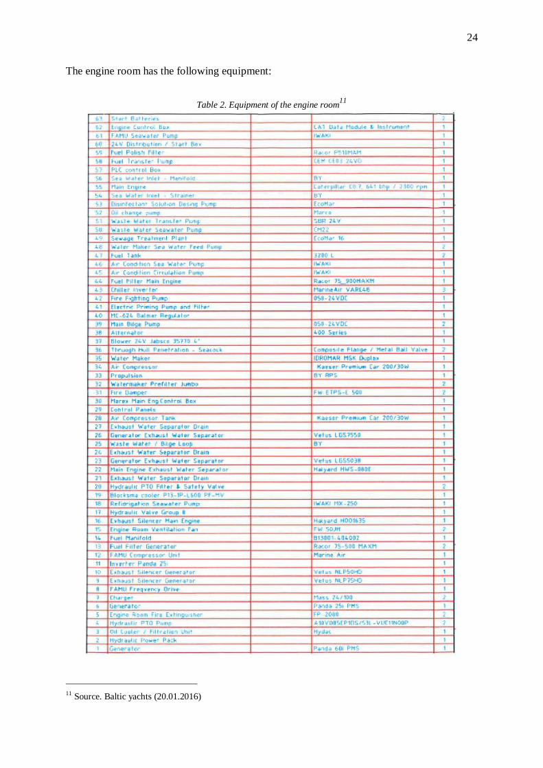
The engine room has the following equipment:
Table 2. Equipment of the engine room11
11 Source. Baltic yachts (20.01.2016)
25
4.1.2. System analysis
The system is very complex and the number of elements is enormous so first of all, groups
have to be made to identify the relevant elements. To determine the level of synthesis is one
of the most important parts because it will make analysis of the system boundaries easier and
at the same time allow us to see the relation between the various parts. Another important
aspect is to define the activities, goals and performance. The purpose of this system is to
generate sufficient energy to supply the boat´s demand.
The system works by decision-analysis and information handling, to try to improve its
efficiency changing the basic components or the relation between the parts.
The system analysis uses the Churchman Theory. Charles West Churchman was an American
philosopher and systems scientist who determined the following purposes of system analysis:
The system's general objectives and the performance indicators of the system will be
very clear.
The environment: the fixed restrictions
The system resources have to be present.
The system's components / parts, their activities, goals and performance indicators.
Think functions / tasks instead of structures
The management of the system. It is important to have the ability to change it.
All of these qualities are relevant in making a functional systems analysis that permits us to
find more efficiency in relation to the working parts. It is impossible to find an improved
efficiency level, if the systems analysis operates poorly.
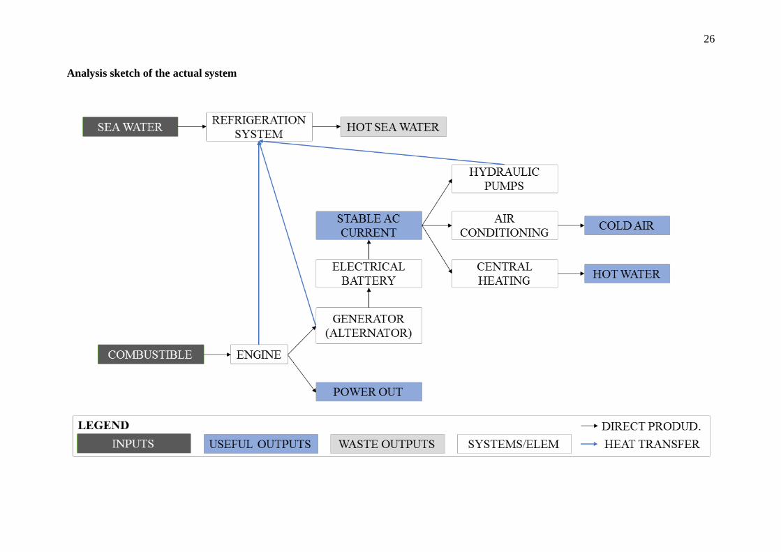
26
Analysis sketch of the actual system
27
4.2. Improvement
4.2.1. Equipment improvements
To improve the equipment it is possible to apply some of the technologies described in
section 2. In the case that it is possible to change the actual diesel engine for another type,
different technologies have to be compared to try to find the best option for supplying the
needs. The same is true for the other equipment which generates losses like the hydraulic
pumps or the generator. In a complex analysis the aspects that have to be analyzed are the
mechanical yield, efficiency, installation and maintenance prices and of course the noise, the
vibrations and the weight.
Engine.
Stirling technology (more efficiency but less power for the same weight) does not
have enough advantages nowadays to replace the actual internal combustion engine.
The weight is the same challenge which has made the fuel cells technology unviable
for this type of boat. However, the new engines by Atkinson and Miller may be in the
immediate future.
In a long term the situation could change a lot; the pressure to reduce the use of fossil
fuels could be enough to change the actual combustion engine on the boat to natural
gas engine or hydrogen fuel cells, instead of diesel. Natural gas and Hydrogen could
dominate the fuel market in the next years.
If natural gas economy takes more importance in the following years, the Stirling will
be more relevant engines for boats. On the other hand, if hydrogen economy wins,
fuel cells will be the best option, specifically, the Phosphoric acid fuel cell (PAFC).
The phosphoric acid fuel cells have a low working temperature, has a high efficiency
if a cogeneration system is used and needs hydrogen less pure.
28
Batteries
Renewable energy and electric boats can play a very important role in the future so
batteries play an important role too.
Ultra-capacitors have some advantages like the speed at which they can be recharged
and the lower weight suggests that they may be a useful addition to boats however the
life of the charge is very short. This problem makes this technology useless on boats.
Superconducting magnetic batteries have the same problem as ultra-capacitors.
In conclusion, only electrochemical batteries can be used nowadays in the
transportation field. In electrochemical batteries Ion-lithium batteries are superior
because they reduce the weight by more than 60%, this type of battery is being used
in some sports cars like Porsche 911 GT3, Porsche 911 GT3 RS y Porsche Boxster
Spyder and they could be an option to reduce the weight.
Hot water accumulator
Hot water accumulators are always necessary on a boat to supply this need
immediately. There are two types of accumulators, the sensible and latent (explained
in section 2). The efficiency is the same for both technologies (very high) but if the
important parameter is the weight the advantages of latent technology which can store
the same amount of energy with less weight and less space, makes the latent
accumulator better.
4.2.2. Reusing energy improvements
There is possible to improve the efficiency of the engine room changing the refrigeration
system. The boat does not currently have any way to reuse this wasted energy, in
consequence loses a large quantity of thermal energy. The refrigeration liquid used is sea
water, which is taken by complex equipment to avoid bubbles. The water temperature at the
beginning is approximately 25ºC and 40ºC at the end of the circuit. To use this energy some
technologies could be applied such as cogeneration or thermoelectric power generation.

29
In the cogeneration this waste energy is used to produce hot water and in trigeneration to
produce cold and hot water. The trigeneration technology is a good solution for this boat
because the part that consumes most energy is the air-conditioning system.
On the other hand, if thermoelectric power generation is applied the waste energy can be used
to produce electrical energy. Although, the electrical energy has more applications in the
boat, the efficiency of this technology is much lower. For this reason, it is better to use
cogeneration when there is a hot water demand.
In conclusion, the best technology for this system is the cogeneration, more specifically the
trigeneration. Nevertheless, if the amount of hot water produced is more than the needs,
cogeneration can be combined with thermoelectric technology.
30
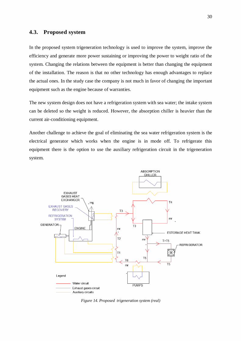
4.3. Proposed system
In the proposed system trigeneration technology is used to improve the system, improve the
efficiency and generate more power sustaining or improving the power to weight ratio of the
system. Changing the relations between the equipment is better than changing the equipment
of the installation. The reason is that no other technology has enough advantages to replace
the actual ones. In the study case the company is not much in favor of changing the important
equipment such as the engine because of warranties.
The new system design does not have a refrigeration system with sea water; the intake system
can be deleted so the weight is reduced. However, the absorption chiller is heavier than the
current air-conditioning equipment.
Another challenge to achieve the goal of eliminating the sea water refrigeration system is the
electrical generator which works when the engine is in mode off. To refrigerate this
equipment there is the option to use the auxiliary refrigeration circuit in the trigeneration
system.
Figure 14. Proposed trigeneration system (real)
.
.
.
.
.
31
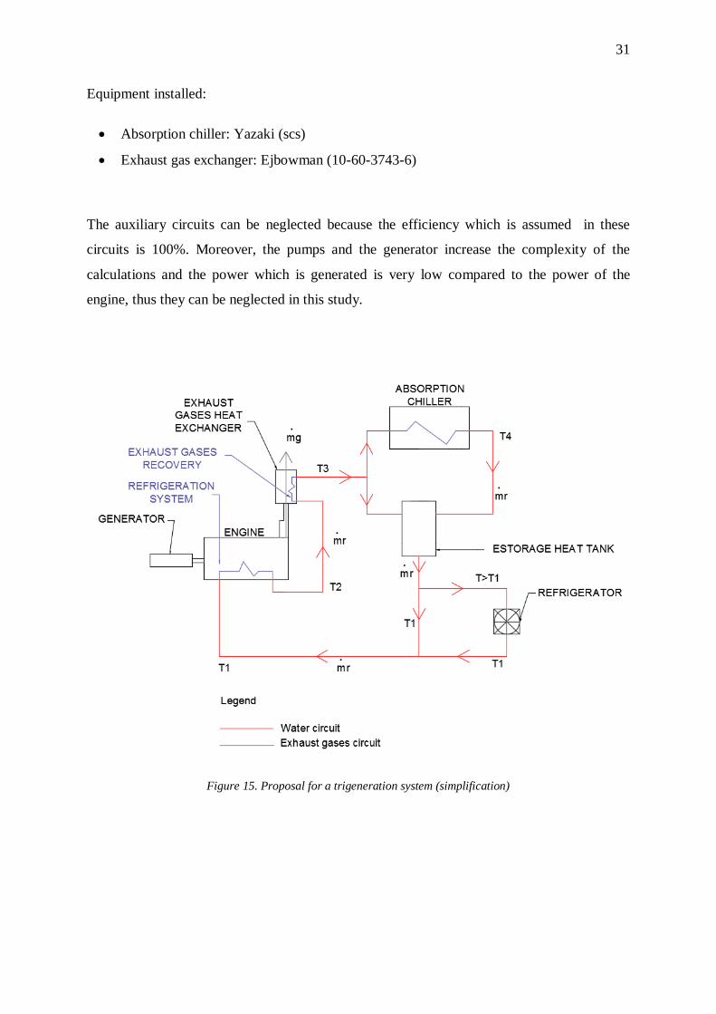
Equipment installed:
Absorption chiller: Yazaki (scs)
Exhaust gas exchanger: Ejbowman (10-60-3743-6)
The auxiliary circuits can be neglected because the efficiency which is assumed in these
circuits is 100%. Moreover, the pumps and the generator increase the complexity of the
calculations and the power which is generated is very low compared to the power of the
engine, thus they can be neglected in this study.
Figure 15. Proposal for a trigeneration system (simplification)
.
.
.
.
.
32
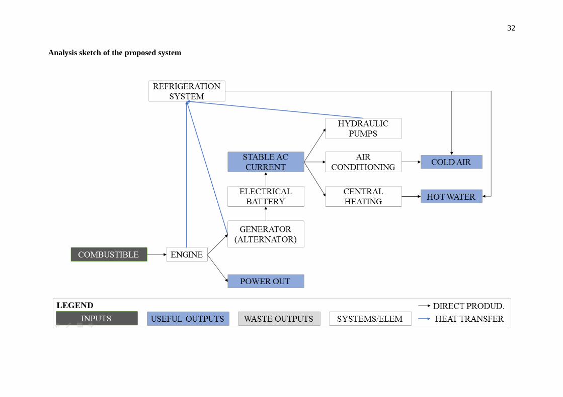
Analysis sketch of the proposed system
33
4.3.1. The energy resource
The proposed system uses the energy of all elements that have thermal losses and that need
a refrigeration system. However, though the engine is the only part considered in this study
in order to simplify the calculations, the results are representative enough. This is the
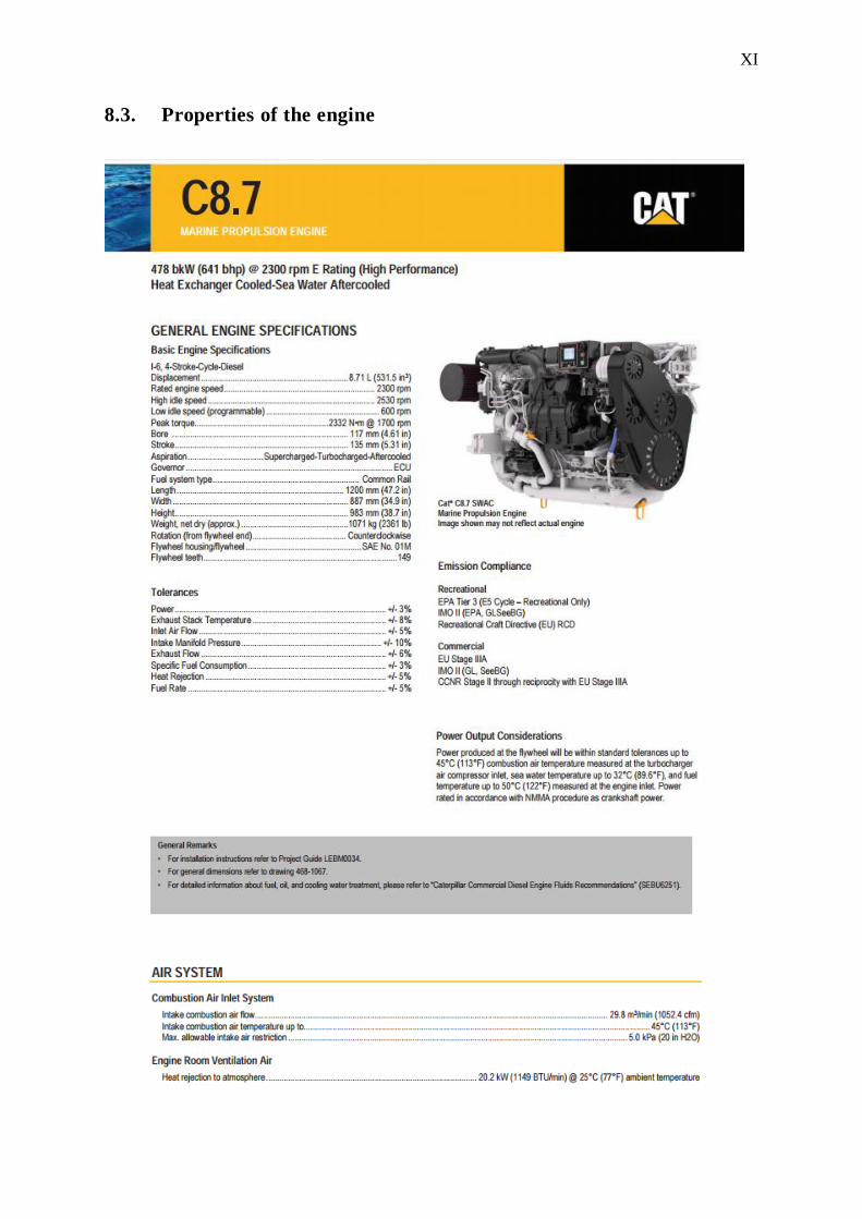
reason why a diesel engine with 478kW is the only element represented in this study. This
type of engines loses approximately 75% of the energy as heat, vibrations and noise.
4.3.2. Systems of heat recuperation
The cogeneration system basically consists in using the waste thermal energy to generate
hot water and in the case of trigeneration cold too. In the engines there are the following
three systems with these particular properties and they can be used to take this energy out:
The main system to reuse the energy is the exhaust escape gases. In a normal
engine these gases can go up to very high temperatures, between 400ºC and 500ºC.
At the exit of the gases it is possible to take the amount of energy that increases the
temperature around 150ºC by a boiler recovery. This limitation is because 150ºC is
the dew point temperature for these gases (the temperature that the gases start to
condensate). This temperature cannot be surpassed.
Another system is the refrigeration system (the water circuit that takes out the
excess of heat inside the engine). This system moves a big amount of water but the
temperatures are not very high. Moreover, there is a minimum exit and entrance
temperatures because it has to achieve another purpose, decrease the temperature of
the engine.
The lubrication system of the engine is another way to obtain energy. The
temperature of this part is 80-90ªC. In a Formula 1 engine it is normal to use a
refrigeration system with oil but in our engine the oil is stored in the carter and
there is no refrigeration system focused on evacuating the excess temperature.
In our system only the heat from the refrigeration system and the exhaust gases is used.
The same water from the refrigeration system takes the heat of the hot exhaust gases. Then
this water is used to produce cold in the absorption chiller or it goes directly to the
accumulator to be used in the central-heating or as hot water.
34
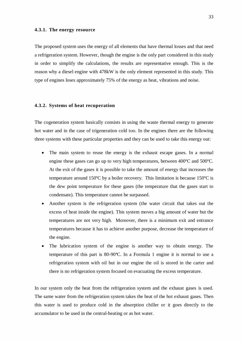
4.3.3. Temperatures, flows and powers
The calculations which are made to find out the following numbers are explained in the
calculations12
:
Temperatures:
Temperature 1: T1= 32ºC
Temperature 2: T2= 51.9ºC
Temperature 3: T3= 96.19ºC
Temperature 4: T4= 90.96ºC
Figure 16. Temperatures in the heat recovery system (heat process)
Flows:
Water flow of the refrigeration system: ṁr =1.15kg/s
Gases flow of the exhaust gases system: ṁg =0.569kg/s
Powers:
Mechanical power: 478kW
Thermal power of the refrigeration system: 95.9kW
Thermal power of the exhaust gases: 212.9kW
Total power of the proposed system: 787kW
125.2. Calculations of the proposed system
Refrigeration system (engine)
Exhaust gases heat exchanger
Apsorb chiller
32ºC 51.9ºṁr= 1.15kg/s 96.19ºC 90.96ºC
35
4.4. Comparison between the systems
4.4.1. kW/kg
The current system: 0.352kW/kg
The proposed system: 0.5kW/kg
The kW extra divided with the kg extra: 1.4 kW/kg
4.4.2. Efficiencies
For the current efficiency there are no data in our system but the value is between 25% and
40% for this type of engines, so the final efficiency value is between these results:
Current efficiency: 25%
Proposed system efficiency: 41%
Current efficiency: 40%
Proposed system efficiency: 66%
36
5. Calculations
5.1. Characteristics values of the systems
The data and assumptions for the new and the current system are the following ones:
Engine properties13
:
Current useful power of the engine: P0= 0= 478kW
o Efficiency of the actual system (only the engine): η0= 25-40%
Refrigeration system:
o Temperature in the entrance of refrigeration system (engine): T1= 32ºC
o Maximum temperature in the exit of refrigeration system (engine): T2=51.9ºC
o Heat rejection to raw water cooling system: 95.9kW
Exhaust system:
o Exhaust stack temperature : Tentrance,gases= 504ºC
o Temperature in the end of the exhaust gases heat recovery: 150ºC
o Exhaust gas flow: ṁg = 2048.3kg/hr ≈0.569 kg/s
Current systems information14
:
Weight of air-conditioning system: 210kg
Weight of sea water intake system: 75kg
13 Source. Catalogue CAT (annex) 14 Source. Discussions/dialogs with Baltic Yachts. (10.03.2016)
37
5.2. Calculations of the proposed system
5.2.1. Powers of the trigeneration system
There are two different systems that generate power which is used by the trigeneration
system to warm the water. The refrigeration system of the engine and the heat recovery
exhaust gases.
Power of refrigeration system
The power of the refrigeration system is defined by the CAT engine catalogue with the
following value14
:
Refrigeration system: Pref = ref =95.9kW
Power of the heat recovery exhausts gases
To determinate the power value of the heat exhausts gases heat recovery; these data have
to be used:
Exhaust stack temperature : Tentrance,gases= 504ºC
Temperature in the end of the exhaust gases heat recovery: 150ºC
Exhaust gas flow: ṁg = 2048.3kg/hr ≈0.569 kg/s
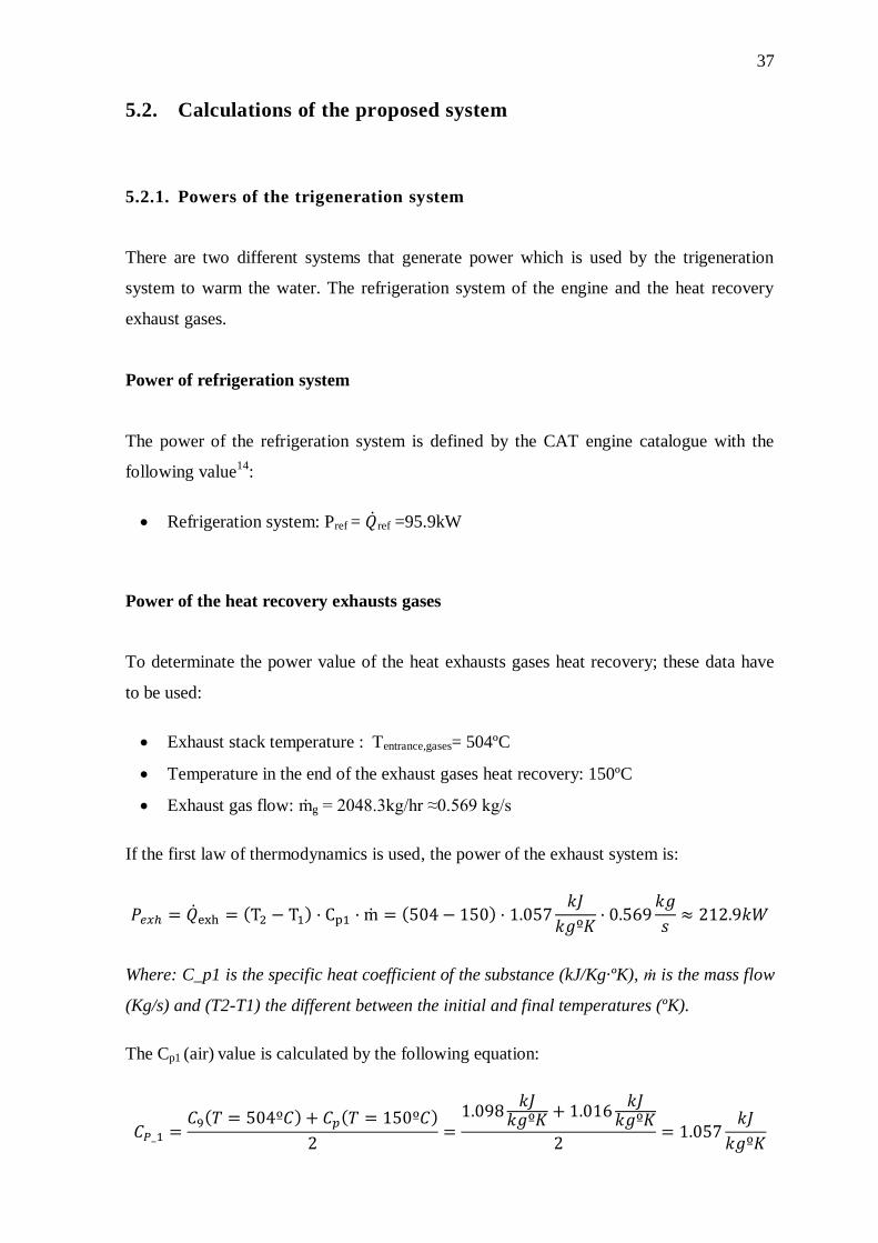
If the first law of thermodynamics is used, the power of the exhaust system is:
( ) ( )
Where: C_p1 is the specific heat coefficient of the substance (kJ/Kg·ºK), ṁ is the mass flow
(Kg/s) and (T2-T1) the different between the initial and final temperatures (ºK).
The Cp1 (air) value is calculated by the following equation:
( ) ( )
38
Total power for the proposed system
The total power for the proposed system is:
( )
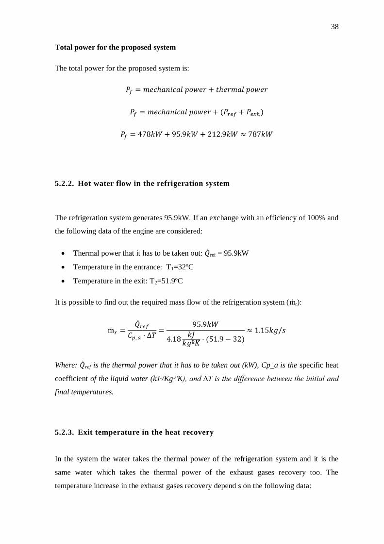
5.2.2. Hot water flow in the refrigeration system
The refrigeration system generates 95.9kW. If an exchange with an efficiency of 100% and
the following data of the engine are considered:
Thermal power that it has to be taken out: ref = 95.9kW
Temperature in the entrance: T1=32ºC
Temperature in the exit: T2=51.9ºC
It is possible to find out the required mass flow of the refrigeration system (ṁr):
( )
Where: ref is the thermal power that it has to be taken out (kW), Cp_a is the specific heat
coefficient of the liquid water (kJ·/Kg·ºK), and ∆T is the difference between the initial and
final temperatures.
5.2.3. Exit temperature in the heat recovery
In the system the water takes the thermal power of the refrigeration system and it is the
same water which takes the thermal power of the exhaust gases recovery too. The
temperature increase in the exhaust gases recovery depend s on the following data:
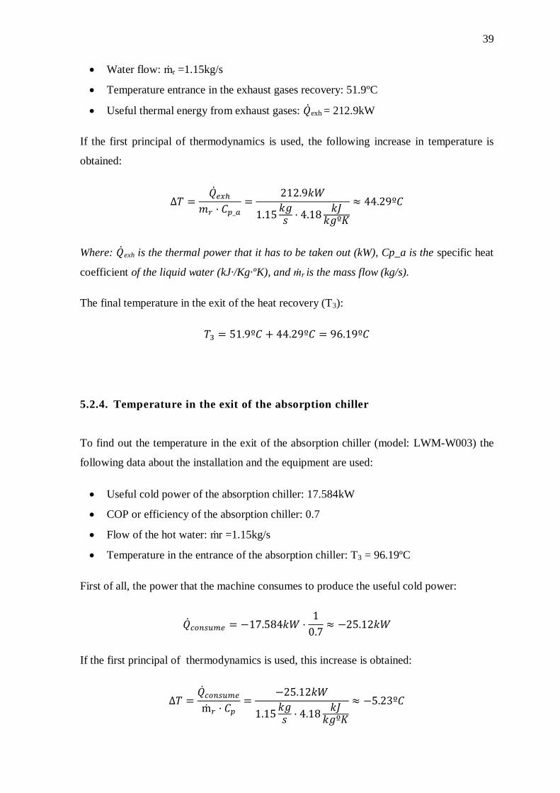
39
Water flow: ṁr =1.15kg/s
Temperature entrance in the exhaust gases recovery: 51.9ºC
Useful thermal energy from exhaust gases: exh = 212.9kW
If the first principal of thermodynamics is used, the following increase in temperature is
obtained:
Where: exh is the thermal power that it has to be taken out (kW), Cp_a is the specific heat
coefficient of the liquid water (kJ·/Kg·ºK), and ṁr is the mass flow (kg/s).
The final temperature in the exit of the heat recovery (T3):
5.2.4. Temperature in the exit of the absorption chiller
To find out the temperature in the exit of the absorption chiller (model: LWM-W003) the
following data about the installation and the equipment are used:
Useful cold power of the absorption chiller: 17.584kW
COP or efficiency of the absorption chiller: 0.7
Flow of the hot water: ṁr =1.15kg/s
Temperature in the entrance of the absorption chiller: T3 = 96.19ºC
First of all, the power that the machine consumes to produce the useful cold power:
If the first principal of thermodynamics is used, this increase is obtained:
40
Where: consume is the thermal power that it has to be taken out (kW), Cp is the Heat
capacity (kJ·/Kg·ºK) of the water, and ṁr is the mass flow (kg/s).
The final temperature in the exit of the heat recovery (T4):
( )
5.3. Comparison between the systems
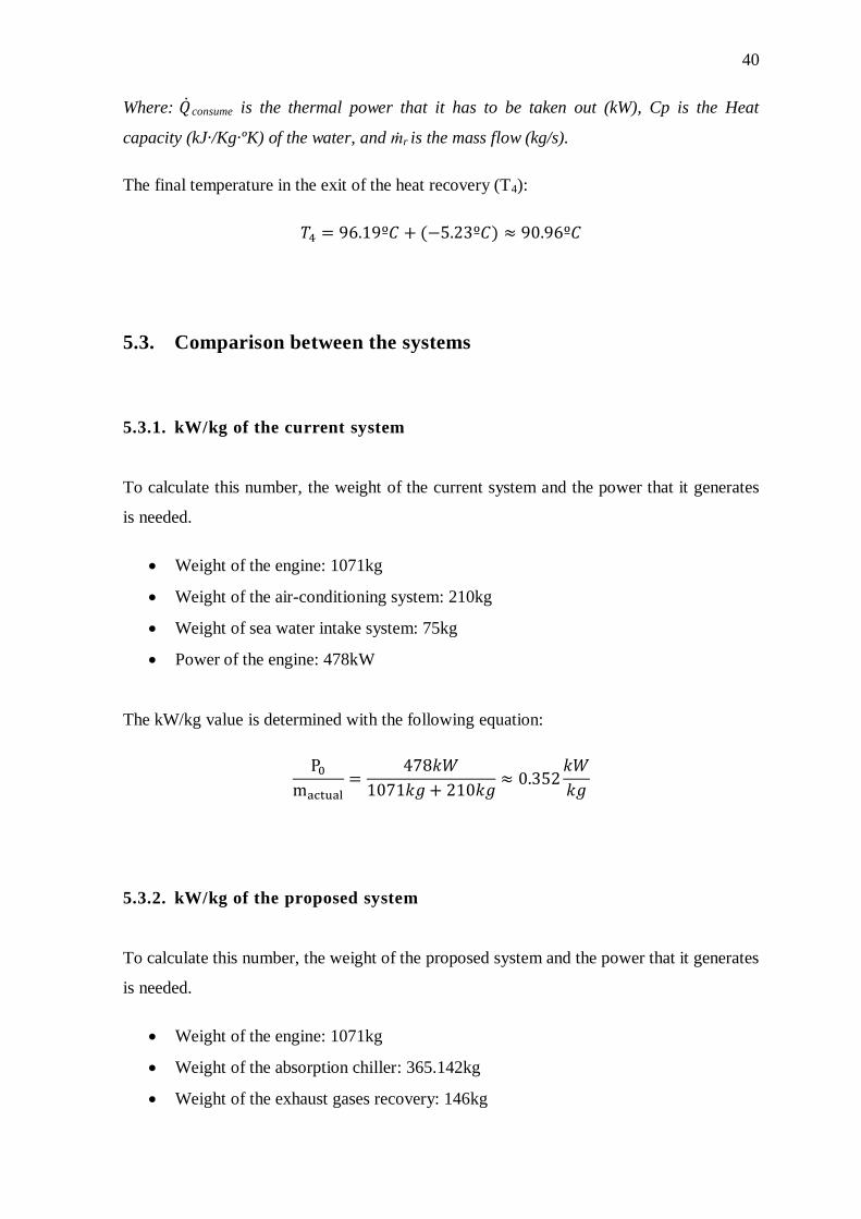
5.3.1. kW/kg of the current system
To calculate this number, the weight of the current system and the power that it generates
is needed.
Weight of the engine: 1071kg
Weight of the air-conditioning system: 210kg
Weight of sea water intake system: 75kg
Power of the engine: 478kW
The kW/kg value is determined with the following equation:
5.3.2. kW/kg of the proposed system
To calculate this number, the weight of the proposed system and the power that it generates
is needed.
Weight of the engine: 1071kg
Weight of the absorption chiller: 365.142kg
Weight of the exhaust gases recovery: 146kg
41
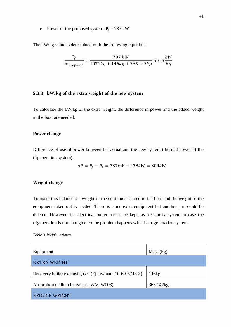
Power of the proposed system: Pf = 787 kW
The kW/kg value is determined with the following equation:
5.3.3. kW/kg of the extra weight of the new system
To calculate the kW/kg of the extra weight, the difference in power and the added weight
in the boat are needed.
Power change
Difference of useful power between the actual and the new system (thermal power of the
trigeneration system):
Weight change
To make this balance the weight of the equipment added to the boat and the weight of the
equipment taken out is needed. There is some extra equipment but another part could be
deleted. However, the electrical boiler has to be kept, as a security system in case the
trigeneration is not enough or some problem happens with the trigeneration system.
Table 3. Weigh variance
Equipment Mass (kg)
EXTRA WEIGHT
Recovery boiler exhaust gases (Ejbowman: 10-60-3743-8) 146kg
Absorption chiller (Ibersolar:LWM-W003) 365.142kg
REDUCE WEIGHT
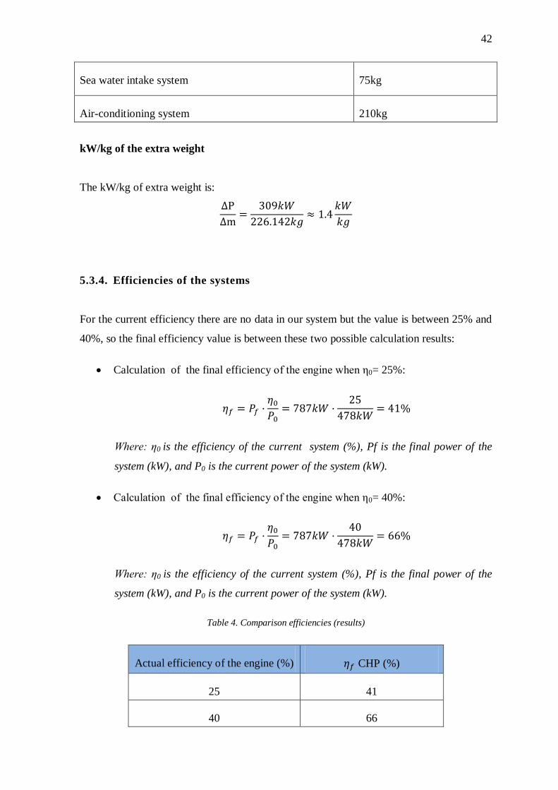
42
Sea water intake system 75kg
Air-conditioning system 210kg
kW/kg of the extra weight
The kW/kg of extra weight is:
5.3.4. Efficiencies of the systems
For the current efficiency there are no data in our system but the value is between 25% and
40%, so the final efficiency value is between these two possible calculation results:
Calculation of the final efficiency of the engine when η0= 25%:
Where: η0 is the efficiency of the current system (%), Pf is the final power of the
system (kW), and P0 is the current power of the system (kW).
Calculation of the final efficiency of the engine when η0= 40%:
Where: η0 is the efficiency of the current system (%), Pf is the final power of the
system (kW), and P0 is the current power of the system (kW).
Table 4. Comparison efficiencies (results)
Actual efficiency of the engine (%) CHP (%)
25 41
40 66
43
6. Conclusion and personal reflection
6.1. Conclusion
A study of the technologies that could be applied in the engine room was essential to have
enough knowledge to determine the best way to improve the engine room.
In the current system all the waste thermal energy produced by the equipment is evacuated
by the refrigeration system to the sea. Reusing this amount of energy is the main idea of
the proposed system.
The trigeneration system that was proposed is a very good option to increase the efficiency
of the system. This efficiency increase depends on the initial efficiency. It increases to 41%
if the initial was 25% or increases to 66% if the initial efficiency was 40%15
. Therefore, in
any case, the improvement is more than 15% and 309 kW of extra power is produced. This
thermal power is used to produce both hot water and cold.
Another comparison is the kW/kg between the proposed and the current systems. These
numbers makes it clear that the trigeneration method is better in the power to weight ratio.
kW/kg of the current system: 0.352 kW/kg
kW/kg of the proposed system: 0.5 kW/kg
The kW per every kg that is added in the installation (1.4kW/kg) is another interesting
number. The number comes from the variance of power and mass between the current and
the proposed system.
The total weights of the boat increases but at the same time the increase in efficiency
means less fuel to carry and of course less economical expense. Moreover, a high
efficiency is synonymous with fewer emissions, so this leads to a more environmentally
friendly boat. Therefore, it can be concluded that the project could be implemented in the
boat.
15 Table 5. Comparison EFFICIENCIES (results)

44
6.2. Personal reflection
In this project I had the possibility to find new technologies in the industrial energy market.
Then I analyzed a real system, the focus of the analysis being on the relation between the
parts because most equipment was already fixed by the company. However, my knowledge
about the different technologies gives an idea about the future and the different
technologies that improve specific parts of the system. These changes will add to the
global efficiency of the boat.
Another reason to be grateful for this project is the fact that I could combine both my
degrees. The first part where I studied new technologies is focused on mechanical
engineering. Secondly, the purpose of this project, improving the efficiency and at the
system analysis, are basically environmental work. In this project I had the possibility to
mix my passions: technology improvements and environmental awareness.
I am very proud of the results of the project. It found some shortcomings in the engine
room system, some blunderings between the parts. At the same time it shows future lines
of work from a more personal point of view, I am happy I had the possibility to work on a
real project. Moreover, visiting the company made me feel like an engineer and I learned
about many projects that I wish to work on, such as: a way to use green water for the
toilets, replacing the current system of refrigeration (two different systems) by more
efficient one and, of course, a kind of solar technology that uses all the sun-light that shines
on the exterior of the boat.
The only downside was the lack of time. I really would like to spend more time on the
project, work in it and find out all the necessary calculations to make the design and, the
prototype. It is my dream to finally see my project working in a real boat.
45
7. Literature references
Agüera Soriano, J. (1996). Mecánica de fluidos incomprensibles i turbomáquinas. (4th ed.)
hidráulicas. Madrid. Editorial ciencia.
Alcantara A. (October 2012). Energetic and Economical Evaluation of the Dimensioning
of Cogeneration and Trigeneration Plants.
https://fenix.tecnico.ulisboa.pt/downloadFile/395144977784/resumo.pdf (retrieved:
10.04.2016).
Baltic Yachts (w.y.) http://www.balticyachts.fi/ (retrieved: 21/02/2016)
Beith R. Small and micro combined heat and power (CHP) systems: Advanced design,
performance, materials and applications. Cambridge (UK): Woodhead publishing, 2011.
Print.
Chamra, Louay M., and Mago, Pedro J. 15 (March 2016). Micro-CHP Power Generation
for Residential and Small Commercial Buildings. Hauppauge, US: Nova Science
Publishers, Inc., 2009. ProQuest ebrary. Web.
Digamber M. Tagare. (2011).Electricity power generation: The changing dimensions. New
Jersey: IEEE press. Print.
Engineeringtoolbox. (w.y). Absolute, Dynamic and Viscoty
http://www.engineeringtoolbox.com/dynamic-absolute-kinematic-viscosity-d_412.html
(retrieved: 12.02.2016)
Galván Villamarín, J. (2016). Simulation of Tri-generation Systems with application of
optimization. KTH Industrial engineering and marketing. Thesis
Gas network irland. (2008). Trigeneration Technology helps Rochestown Park Hotel to do
it again. Case study
http://www.gasnetworks.ie/Global/Customer%20Care%20Uploads%20GNI/30%20GNI%
20Trigeneration%20Case%20Study.pdf (retrieved: 11.03.2016).
46
Kreith F. and D. Yogi Goswami. (2008).Energy conversion. Broken Sound Parkway NW.
Taylor and Francis group. Print
Lozano Miguel Á. Ramos José, Sanchez Silvia. (2004). Optimización del diseño de
sistemas de trigeneracion. University of Zaragoza.
Marrero Jerez, J. (2015). Síntesis y caracterización de materiales basados en ceria para
pilas de combustible de óxidos sólidos. Universidad de La Lengua. Thesis
Minciuc E. (w.y). Trigeneration in tertiary sector: a case study. (Report). Romania:
University Politehnica of Bucharest.
Risku C. (2016). System analysis. Vaasa: Novia university; Academic material
Suárez Vidal, G. (2007). Instalación de trigeneración mediante motores de gas. Madrid:
Universidad Pontificia Comillas. Thesis
T. D. Eastop and D. R. Croft. (1990). Energy efficiency: for engineers and technologists.
Harlow (England): Longman. Print.
Yazaki . (2016). Trigeneration system
http://www.yazakiairconditioning.com/fileadmin/templates/img_airconditioning/swf/1008
_cchp_trigen_EN.html (retrieved: 16.03.2016).
I
8. Appendices
8.1. Equipment selection
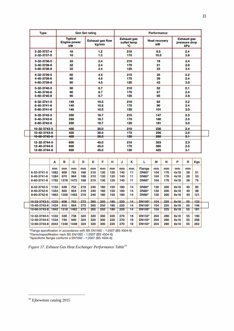
8.1.1. Exhaust gas heat exchanger selection
The important parameter to select the recovery exhaust gases equipment is the power that it
has to collect. However, all this properties could be considered:
Heat power take of the gases: Pexh = exh = 212.9kW
Engine power: P0 = 478kW
Gases temperature in the entrance of the exhaust gas heat exchanger: Tentramce,gases
=504ºC
Gases temperature in the exit of the exhaust gas heat exchanger: 150ºC
Gases flow: ṁg =0.569 kg/s
The equipment which is selected is the Ejbowman: 10-60-3743-6. This equipment has the
perfect characteristics for this trigeneration system.
II
Figure 17. Exhaust Gas Heat Exchanger Performance Table16
16 Ejbowman catalog 2015
III
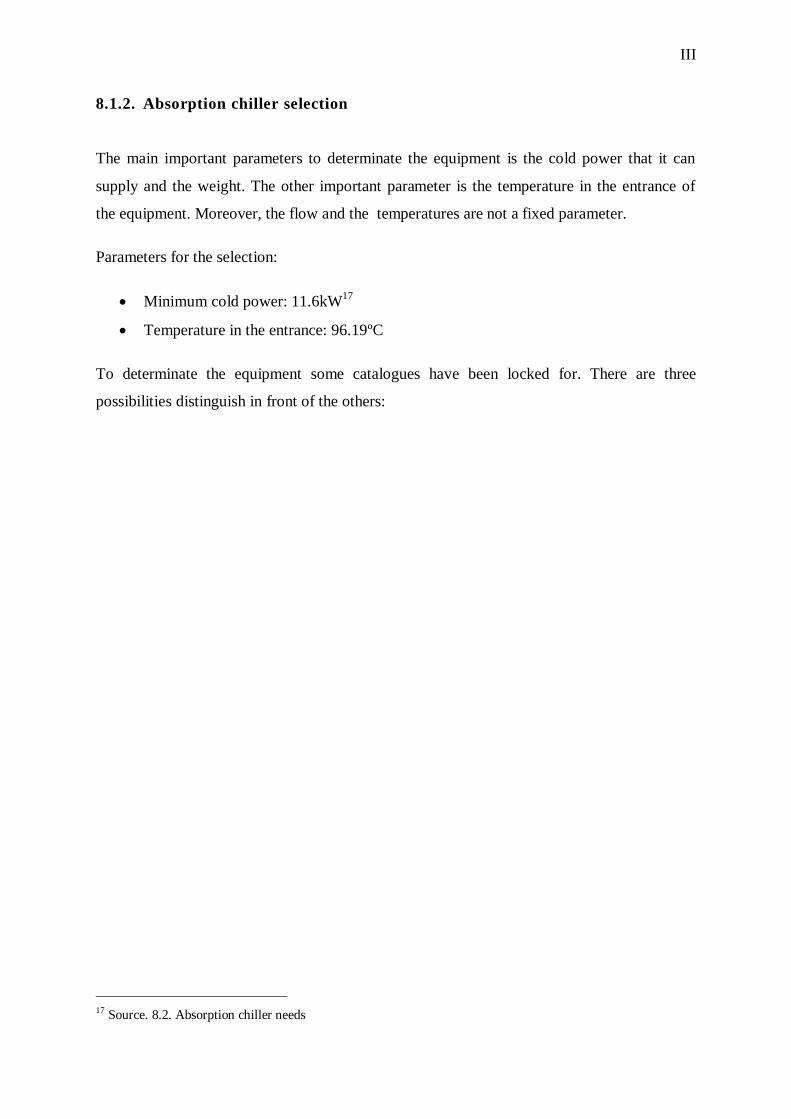
8.1.2. Absorption chiller selection
The main important parameters to determinate the equipment is the cold power that it can
supply and the weight. The other important parameter is the temperature in the entrance of
the equipment. Moreover, the flow and the temperatures are not a fixed parameter.
Parameters for the selection:
Minimum cold power: 11.6kW17
Temperature in the entrance: 96.19ºC
To determinate the equipment some catalogues have been locked for. There are three
possibilities distinguish in front of the others:
17 Source. 8.2. Absorption chiller needs
IV
1. Ibersolar model
Figure 18. Catalogue Ibersolar
Technic information Ibersolar:
This machine has a COP =0.7
The common hot water in the entrance is 85-90ºC
V
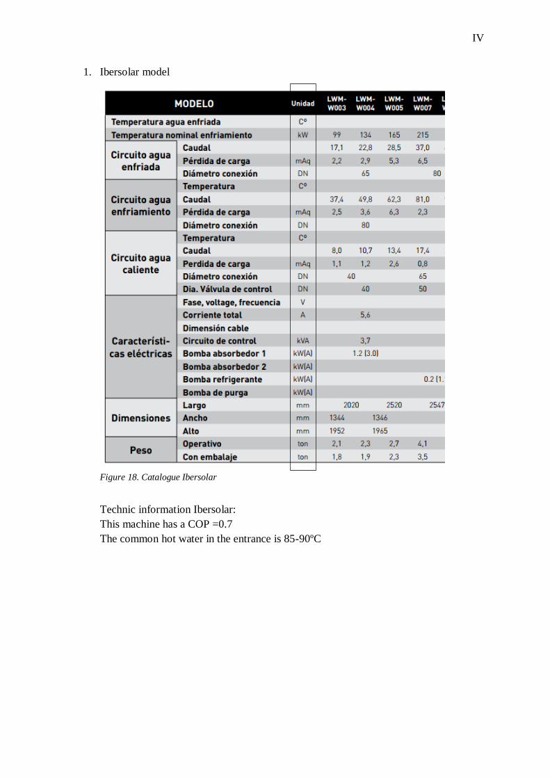
2. Biobestenergy model
Figure 19. Catalogue Biobestenergy
Technic information Biobestenergy:
The pressure of chilled water circuit and cooling are based on 1,0MPa (150 psig) and
1,6MPa (230psig) for the hot water circuit.
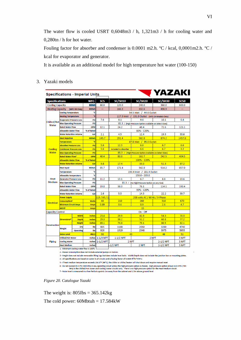
VI
The water flow is cooled USRT 0,6048m3 / h, 1,321m3 / h for cooling water and
0,280tn / h for hot water.
Fouling factor for absorber and condenser is 0.0001 m2.h. ºC / kcal, 0,0001m2.h. ºC /
kcal for evaporator and generator.
It is available as an additional model for high temperature hot water (100-150)
3. Yazaki models
Figure 20. Catalogue Yazaki
The weight is: 805Ibs = 365.142kg
The cold power: 60Mbtuh = 17.584kW

VII
Selection:
The option selected is the Yazaki scs model absorption chiller. This one is the lighter and the
restrictions (exit temperatures and the flow) are more flexible. Consequently, it is the best
option in our trigeneration system.
VIII
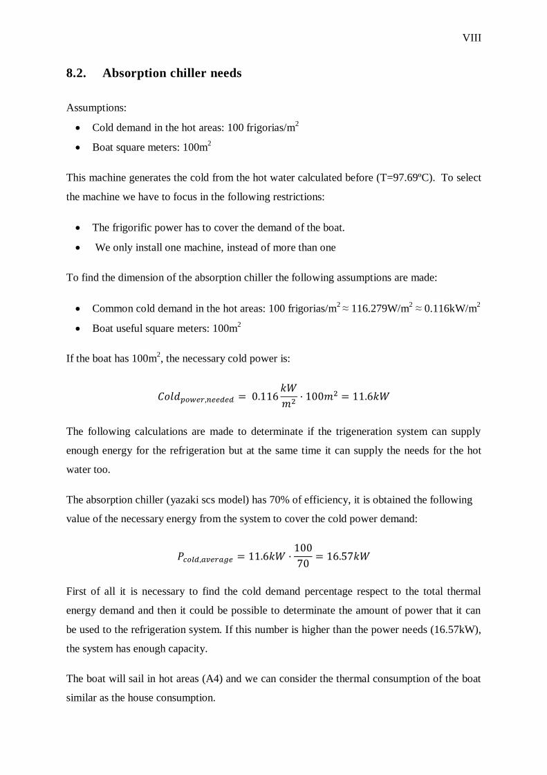
8.2. Absorption chiller needs
Assumptions:
Cold demand in the hot areas: 100 frigorias/m2
Boat square meters: 100m2
This machine generates the cold from the hot water calculated before (T=97.69ºC). To select
the machine we have to focus in the following restrictions:
The frigorific power has to cover the demand of the boat.
We only install one machine, instead of more than one
To find the dimension of the absorption chiller the following assumptions are made:
Common cold demand in the hot areas: 100 frigorias/m2
≈ 116.279W/m2 ≈ 0.116kW/m
2
Boat useful square meters: 100m2
If the boat has 100m2, the necessary cold power is:
The following calculations are made to determinate if the trigeneration system can supply
enough energy for the refrigeration but at the same time it can supply the needs for the hot
water too.
The absorption chiller (yazaki scs model) has 70% of efficiency, it is obtained the following
value of the necessary energy from the system to cover the cold power demand:
First of all it is necessary to find the cold demand percentage respect to the total thermal
energy demand and then it could be possible to determinate the amount of power that it can
be used to the refrigeration system. If this number is higher than the power needs (16.57kW),
the system has enough capacity.
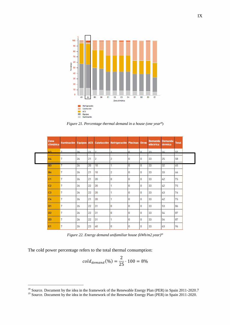
The boat will sail in hot areas (A4) and we can consider the thermal consumption of the boat
similar as the house consumption.
IX
Figure 21. Percentage thermal demand in a house (one year18)
Figure 22. Energy demand unifamiliar house (kWh/m2.year)19
The cold power percentage refers to the total thermal consumption:
( )
18 Source. Document by the idea in the framework of the Renewable Energy Plan (PER) in Spain 2011-2020.7 19 Source. Document by the idea in the framework of the Renewable Energy Plan (PER) in Spain 2011-2020.

X
The useful power is 787kW. This power is distributed between the cold production and the
hot water. The cold water is 8% so the absorption chiller could use the following power:
It is possible to see that the necessary power is lower than the power for the absorption
chiller. In conclusion, the installation is enough to supply the power for the cold system.
XI
8.3. Properties of the engine
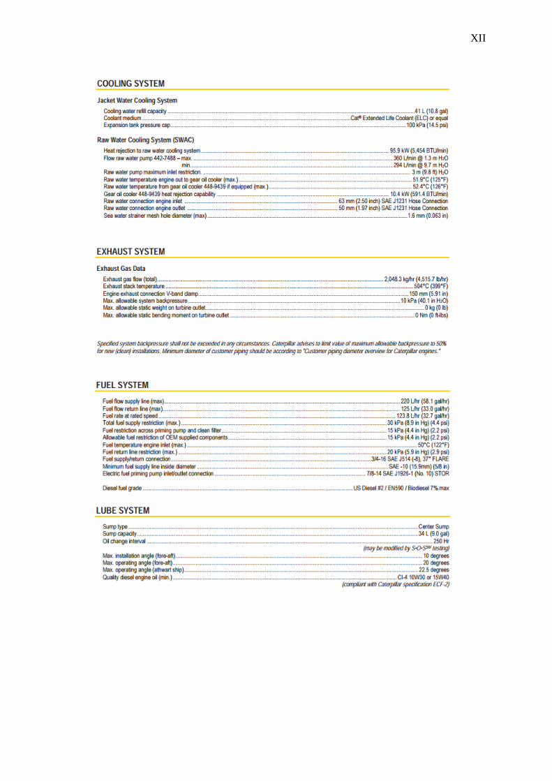
XII

XIII