Embed Size (px)
Citation preview
PN 3028662 August 2007 © 2007 Fluke Corporation, All rights reserved. Printed in USA All product names are trademarks of their respective companies.
Impulse 6000D Defibrillator Analyzer
Impulse 7000DP Defibrillator/Transcutaneous Pacer Analyzer
Getting Started Manual

Warranty and Product Support
Fluke Biomedical warrants this instrument against defects in materials and workmanship for one year from the date of origi-nal purchase OR two years if at the end of your first year you send the instrument to a Fluke Biomedical service center for calibration. You will be charged our customary fee for such calibration. During the warranty period, we will repair or at our option replace, at no charge, a product that proves to be defective, provided you return the product, shipping prepaid, to Fluke Biomedical. This warranty covers the original purchaser only and is not transferable. The warranty does not apply if the product has been damaged by accident or misuse or has been serviced or modified by anyone other than an authorized Fluke Biomedical service facility. NO OTHER WARRANTIES, SUCH AS FITNESS FOR A PARTICULAR PURPOSE, ARE EXPRESSED OR IMPLIED. FLUKE SHALL NOT BE LIABLE FOR ANY SPECIAL, INDIRECT, INCIDENTAL OR CONSE-QUENTIAL DAMAGES OR LOSSES, INCLUDING LOSS OF DATA, ARISING FROM ANY CAUSE OR THEORY.
This warranty covers only serialized products and their accessory items that bear a distinct serial number tag. Recalibration of instruments is not covered under the warranty.
This warranty gives you specific legal rights and you may also have other rights that vary in different jurisdictions. Since some jurisdictions do not allow the exclusion or limitation of an implied warranty or of incidental or consequential damages, this limitation of liability may not apply to you. If any provision of this warranty is held invalid or unenforceable by a court or other decision-maker of competent jurisdiction, such holding will not affect the validity or enforceability of any other provision.
7/07
Notices
All Rights Reserved © Copyright 2007, Fluke Biomedical. No part of this publication may be reproduced, transmitted, transcribed, stored in a retrieval system, or translated into any language without the written permission of Fluke Biomedical.
Copyright Release Fluke Biomedical agrees to a limited copyright release that allows you to reproduce manuals and other printed materials for use in service training programs and other technical publications. If you would like other reproductions or distributions, submit a written request to Fluke Biomedical.
Unpacking and Inspection Follow standard receiving practices upon receipt of the instrument. Check the shipping carton for damage. If damage is found, stop unpacking the instrument. Notify the carrier and ask for an agent to be present while the instrument is unpacked. There are no special unpacking instructions, but be careful not to dam-age the instrument when unpacking it. Inspect the instrument for physical damage such as bent or broken parts, dents, or scratches.
Technical Support For application support or answers to technical questions, either email [email protected] or call 1-800- 648-7952 or 1-425-446-6945.
Claims Our routine method of shipment is via common carrier, FOB origin. Upon delivery, if physical damage is found, retain all packing materials in their original condition and contact the carrier immediately to file a claim. If the instrument is delivered in good physical condition but does not operate within specifica-tions, or if there are any other problems not caused by shipping damage, please contact Fluke Biomedical or your local sales representative.
Standard Terms and Conditions Refunds and Credits
Please note that only serialized products and their accessory items (i.e., products and items bearing a distinct serial number tag) are eligible for partial refund and/or credit. Nonserialized parts and accessory items (e.g., cables, carrying cases, auxiliary modules, etc.) are not eligible for re-turn or refund. Only products returned within 90 days from the date of original purchase are eligible for refund/credit. In order to receive a partial re-fund/credit of a product purchase price on a serialized product, the product must not have been damaged by the customer or by the carrier chosen by the cus-tomer to return the goods, and the product must be returned complete (meaning with all manuals, cables, accessories, etc.) and in “as new” and resalable con-dition. Products not returned within 90 days of purchase, or products which are not in “as new” and resalable condition, are not eligible for credit return and will be returned to the customer. The Return Procedure (see below) must be followed to assure prompt refund/credit.
Restocking Charges Products returned within 30 days of original purchase are subject to a minimum restocking fee of 15 %. Products returned in excess of 30 days af-ter purchase, but prior to 90 days, are subject to a minimum restocking fee of 20 %. Additional charges for damage and/or missing parts and accesso-ries will be applied to all returns.
Return Procedure All items being returned (including all warranty-claim shipments) must be sent freight-prepaid to our factory location. When you return an instrument to Fluke Biomedical, we recommend using United Parcel Service, Federal Express, or Air Parcel Post. We also recommend that you insure your shipment for its actual replacement cost. Fluke Biomedical will not be responsible for lost shipments or instruments that are received in damaged condition due to improper packaging or handling. Use the original carton and packaging material for shipment. If they are not available, we recommend the following guide for repackaging:
Use a double–walled carton of sufficient strength for the weight being shipped. Use heavy paper or cardboard to protect all instrument surfaces. Use nonabrasive material around all projecting parts. Use at least four inches of tightly packed, industry-approved, shock-absorbent material around the instrument.
Returns for partial refund/credit: Every product returned for refund/credit must be accompanied by a Return Material Authorization (RMA) number, obtained from our Order Entry Group at 1-800-648-7952 or 1-425-446-6945. Repair and calibration: To find the nearest service center, go to www.flukebiomedical.com/service or In the U.S.A.: Cleveland Calibration Lab Tel: 1-800-850-4606 Email: [email protected] Everett Calibration Lab Tel: 1-888-99 FLUKE (1-888-993-5853) Email: [email protected] In Europe, Middle East, and Africa: Eindhoven Calibration Lab Tel: +31-402-675300 Email: [email protected] In Asia: Everett Calibration Lab Tel: +425-446-6945 Email: [email protected]
Certification This instrument was thoroughly tested and inspected. It was found to meet Fluke Biomedical’s manufacturing specifications when it was shipped from the factory. Calibration measurements are traceable to the National Institute of Standards and Technology (NIST). Devices for which there are no NIST calibra-tion standards are measured against in-house performance standards using accepted test procedures.
WARNING Unauthorized user modifications or application beyond the published specifications may result in electrical shock hazards or improper operation. Fluke Bio-medical will not be responsible for any injuries sustained due to unauthorized equipment modifications.
Restrictions and Liabilities Information in this document is subject to change and does not represent a commitment by Fluke Biomedical. Changes made to the information in this document will be incorporated in new editions of the publication. No responsibility is assumed by Fluke Biomedical for the use or reliability of software or equipment that is not supplied by Fluke Biomedical, or by its affiliated dealers.
Manufacturing Location The Impulse 6000D and 7000DP Defibrillator/Transcutaneous Pacer Analyzers are manufactured at Fluke Biomedical, 6920 Seaway Blvd., Everett, WA, U.S.A.
i
Table of Contents
Title Page Introduction .................................................................................................................... 1 Intended Use.................................................................................................................. 1 Unpacking the Analyzer ................................................................................................. 1 Safety Information .......................................................................................................... 2 Instrument Familiarization .............................................................................................. 4 Turning the Analyzer On ................................................................................................ 7 Connecting a Defibrillator and Pacer to the Analyzer ..................................................... 7 Accessing the Analyzer Tests ........................................................................................ 8 What to Do Next ............................................................................................................. 12 Maintenance................................................................................................................... 12
Cleaning the Analyzer ............................................................................................... 12 Maintaining Peak Battery Condition........................................................................... 12
Accessories .................................................................................................................... 13 Specifications ................................................................................................................. 14
General Specifications............................................................................................... 14 Defibrillator Analyzer Specifications .......................................................................... 15
Energy Output Measurement................................................................................ 15
Impulse 6000D, 7000DP Getting Started Manual
ii
ECG Waves ......................................................................................................... 17 Transcutaneous Pacemaker Analyzer Specifications (Impulse 7000DP only) .......... 22
Test Load Selections............................................................................................ 22 Measurements...................................................................................................... 22 Demand and Asynchronous Mode Test ............................................................... 23 Sensitivity Test ..................................................................................................... 24 Refractory Period Tests........................................................................................ 24

iii
List of Tables
Table Title Page
1. Symbols................................................................................................................................. 2 2. Top-Panel Controls and Connections.................................................................................... 5 3. Rear-Panel Connections ....................................................................................................... 7 4. Accessories ........................................................................................................................... 13

Impulse 6000D, 7000DP Getting Started Manual
iv
v
List of Figures
Figure Title Page
1. Top-Panel Controls and Connections.................................................................................... 4 2. Rear-Panel Connections ....................................................................................................... 6 3. Analyzer Ready Display ........................................................................................................ 7 4. Defib Function Menu ............................................................................................................. 8 5. Cursor Navigation Example................................................................................................... 8 6. Defibrillator Connections ....................................................................................................... 9 7. Pacer Connections ................................................................................................................ 11 8. ECG Connections.................................................................................................................. 11

Impulse 6000D, 7000DP Getting Started Manual
vi
1
Defibrillator/Pacer Analyzer
Introduction The Impulse 6000D and 7000DP (hereafter the Analyzer) are portable, battery-powered precision instruments for testing external defibrillators. The 7000DP has the added capability of testing trancutaneous pacemakers. Where the additional pacemaker testing capability is applicable, this manual qualifies the description with “7000DP only.” The model 7000DP appears in all product illustrations.
Intended Use The Analyzer is intended for use by trained service technicians to perform periodic inspections on a wide range of cardiac resuscitation equipment. The testing procedures are menu-driven, and simple to operate.
Unpacking the Analyzer Carefully unpack all items from the box and check that you have the following items:
• Impulse 6000D or 7000DP
• Battery charger
• Getting Started Manual
• Users Manual CD
• Defib paddle contact plates
• Impulse 6000D 7000DP Ansur Software CD (demo)
Impulse 6000D, 7000DP Getting Started Manual
2
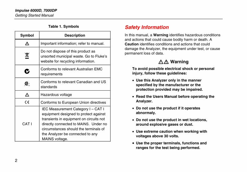
Table 1. Symbols
Symbol Description
W Important information; refer to manual.
~ Do not dispose of this product as unsorted municipal waste. Go to Fluke’s website for recycling information.
; Conforms to relevant Australian EMC requirements
) Conforms to relevant Canadian and US standards
X Hazardous voltage
P Conforms to European Union directives
CAT I
IEC Measurement Category I – CAT I equipment designed to protect against transients in equipment on circuits not directly connected to MAINS. Under no circumstances should the terminals of the Analyzer be connected to any MAINS voltage.
Safety Information In this manual, a Warning identifies hazardous conditions and actions that could cause bodily harm or death. A Caution identifies conditions and actions that could damage the Analyzer, the equipment under test, or cause permanent loss of data.
XW Warning To avoid possible electrical shock or personal injury, follow these guidelines:
• Use this Analyzer only in the manner specified by the manufacturer or the protection provided may be impaired.
• Read the Users Manual before operating the Analyzer.
• Do not use the product if it operates abnormaly.
• Do not use the product in wet locations, around explosive gases or dust.
• Use extreme caution when working with voltages above 30 volts.
• Use the proper terminals, functions and ranges for the test being performed.
Defibrillator/Transcutaneous Pacer Analyzer Safety Information
3
• Do not operate the Analyzer with the battery eliminator connected, unless connected directly to mains power. During battery operation, completely remove the battery eliminator/charger from both the Analyzer and wall socket.
• Observe all precautions noted by the Device Under Test (DUT) equipment manufacturer when analyzing the DUT.
Impulse 6000D, 7000DP Getting Started Manual
4
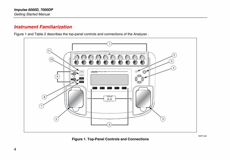
Instrument Familiarization Figure 1 and Table 2 describes the top-panel controls and connections of the Analyzer .
DEFIBRILLATOR5000 Vp MAX
275 V MAX
1
6
2
3
4
7
5 5
8
10
11
9
fak07.eps
Figure 1. Top-Panel Controls and Connections
Defibrillator/Transcutaneous Pacer Analyzer Instrument Familiarization
5
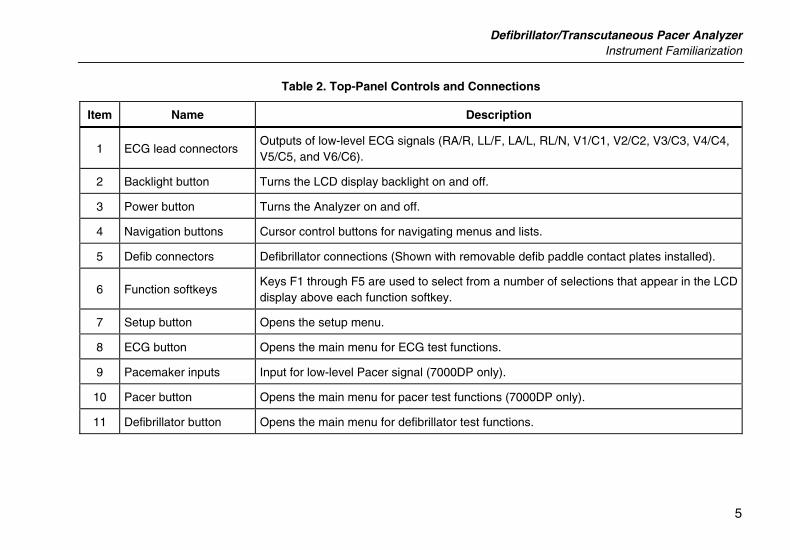
Table 2. Top-Panel Controls and Connections
Item Name Description
1 ECG lead connectors Outputs of low-level ECG signals (RA/R, LL/F, LA/L, RL/N, V1/C1, V2/C2, V3/C3, V4/C4, V5/C5, and V6/C6).
2 Backlight button Turns the LCD display backlight on and off.
3 Power button Turns the Analyzer on and off.
4 Navigation buttons Cursor control buttons for navigating menus and lists.
5 Defib connectors Defibrillator connections (Shown with removable defib paddle contact plates installed).
6 Function softkeys Keys F1 through F5 are used to select from a number of selections that appear in the LCD display above each function softkey.
7 Setup button Opens the setup menu.
8 ECG button Opens the main menu for ECG test functions.
9 Pacemaker inputs Input for low-level Pacer signal (7000DP only).
10 Pacer button Opens the main menu for pacer test functions (7000DP only).
11 Defibrillator button Opens the main menu for defibrillator test functions.
Impulse 6000D, 7000DP Getting Started Manual
6
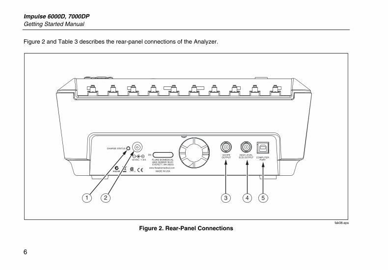
Figure 2 and Table 3 describes the rear-panel connections of the Analyzer.
FLUKE BIOMEDICAL6920 SEAWAY BLVDEVERETT, WA 98203
www.flukebiomedical.com
MADE IN USA
SN SERIAL NUMBERCOMPUTER
PORT
SCOPEOUTPUT
CHARGE STATUS
15 VDC / 1.5A
HIGH LEVELECG OUTPUT
21 3 4 5
fak08.eps
Figure 2. Rear-Panel Connections
Defibrillator/Transcutaneous Pacer Analyzer Turning the Analyzer On
7
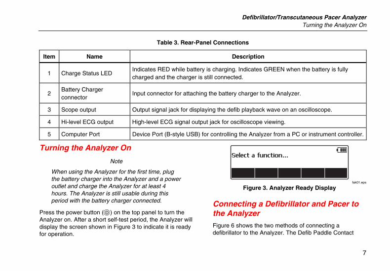
Table 3. Rear-Panel Connections
Item Name Description
1 Charge Status LED Indicates RED while battery is charging. Indicates GREEN when the battery is fully charged and the charger is still connected.
2 Battery Charger connector
Input connector for attaching the battery charger to the Analyzer.
3 Scope output Output signal jack for displaying the defib playback wave on an oscilloscope.
4 Hi-level ECG output High-level ECG signal output jack for oscilloscope viewing.
5 Computer Port Device Port (B-style USB) for controlling the Analyzer from a PC or instrument controller.
Turning the Analyzer On
Note
When using the Analyzer for the first time, plug the battery charger into the Analyzer and a power outlet and charge the Analyzer for at least 4 hours. The Analyzer is still usable during this period with the battery charger connected.
Press the power button (O) on the top panel to turn the Analyzer on. After a short self-test period, the Analyzer will display the screen shown in Figure 3 to indicate it is ready for operation.
fak01.eps
Figure 3. Analyzer Ready Display
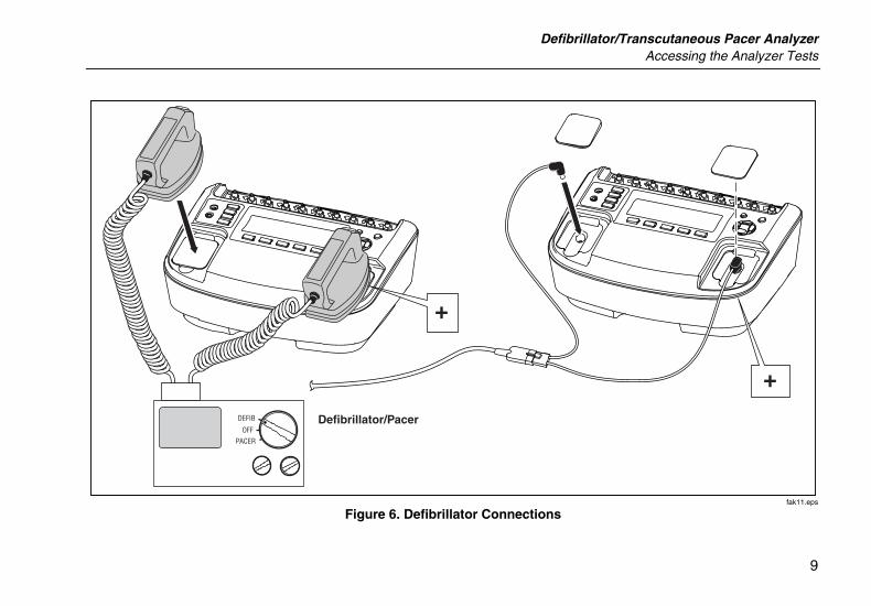
Connecting a Defibrillator and Pacer to the Analyzer Figure 6 shows the two methods of connecting a defibrillator to the Analyzer. The Defib Paddle Contact
Impulse 6000D, 7000DP Getting Started Manual
8
plates are inserted into the defibrillator jacks when external defibrillator paddles are used on the defibrillator.
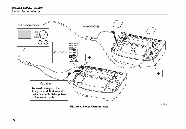
W Caution
To avoid damage to the Analyzer or defibrillator, do not apply defibrillator pulses to the pacer inputs.
Figure 7 shows the pacer connected to either the pacer input jacks or the defibrillator jacks. While the pacer input jacks have a selectable load from 50 to 1500 Ω, the defibrillator input jacks have a fixed load of 50 Ω.
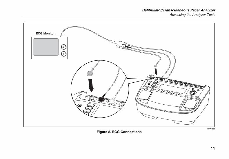
Figure 8 shows how to connect the ECG leads to the Analyzer.
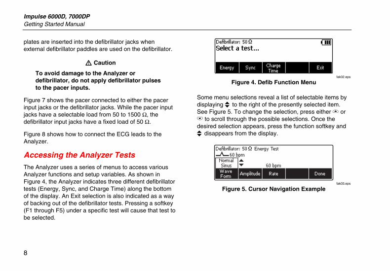
Accessing the Analyzer Tests The Analyzer uses a series of menus to access various Analyzer functions and setup variables. As shown in Figure 4, the Analyzer indicates three different defibrillator tests (Energy, Sync, and Charge Time) along the bottom of the display. An Exit selection is also indicated as a way of backing out of the defibrillator tests. Pressing a softkey (F1 through F5) under a specific test will cause that test to be selected.
fak02.eps
Figure 4. Defib Function Menu
Some menu selections reveal a list of selectable items by displaying K to the right of the presently selected item. See Figure 5. To change the selection, press either G or H to scroll through the possible selections. Once the desired selection appears, press the function softkey and K disappears from the display.
fak03.eps
Figure 5. Cursor Navigation Example
Defibrillator/Transcutaneous Pacer Analyzer Accessing the Analyzer Tests
9
OFF
DEFIB Defibrillator/Pacer
PACER
+
+
fak11.eps
Figure 6. Defibrillator Connections
Impulse 6000D, 7000DP Getting Started Manual
10
OFF
DEFIB
Defibrillator/Pacer 7000DP Only
50 ΩOnly
PACER
+
+
Caution
To avoid damage to the Analyzer or defibrillator, do not apply defibrillator pulses to the pacer inputs.
50 - 1500 Ω
fak10.eps
Figure 7. Pacer Connections
Defibrillator/Transcutaneous Pacer Analyzer Accessing the Analyzer Tests
11
ECG Monitor
fak09.eps
Figure 8. ECG Connections
Impulse 6000D, 7000DP Getting Started Manual
12
What to Do Next For more information on how to use the Analyzer, refer to the Impulse 6000D, 7000DP Users Manual contained on the accompanying CD.
Maintenance The Analyzer needs little maintenance or special care. However, treat it as a calibrated measuring instrument. Avoid dropping or other mechanical abuse that could cause a shift in the calibrated settings. The Analyzer has no internal user serviceable parts.
Cleaning the Analyzer
W Caution
Do not pour fluid onto the Analyzer surface; fluid seepage into the electrical circuitry may cause the Analyzer to fail.
W Caution
Do not use spray cleaners on the Analyzer; such action may force cleaning fluid into the Analyzer and damage electronic components.
Clean the Analyzer occasionally utilizing a damp cloth and mild detergent. Take care to prevent the entrance of liquids.
Wipe down the adapter cables with the same care. Inspect them for damage to and deterioration of the insulation. Check the connections for integrity before each use.
Maintaining Peak Battery Condition
To maintain peak battery capacity, the Analyzer should be charged completely at least once a month. If the Analyzer is to be left idle for more than a month and it is inconvenient to periodically connect to the battery charger, keep it connected to the charger while idle.
Note
To obtain the specified performance, use the battery charger specified in this manual.
Defibrillator/Transcutaneous Pacer Analyzer Accessories
13
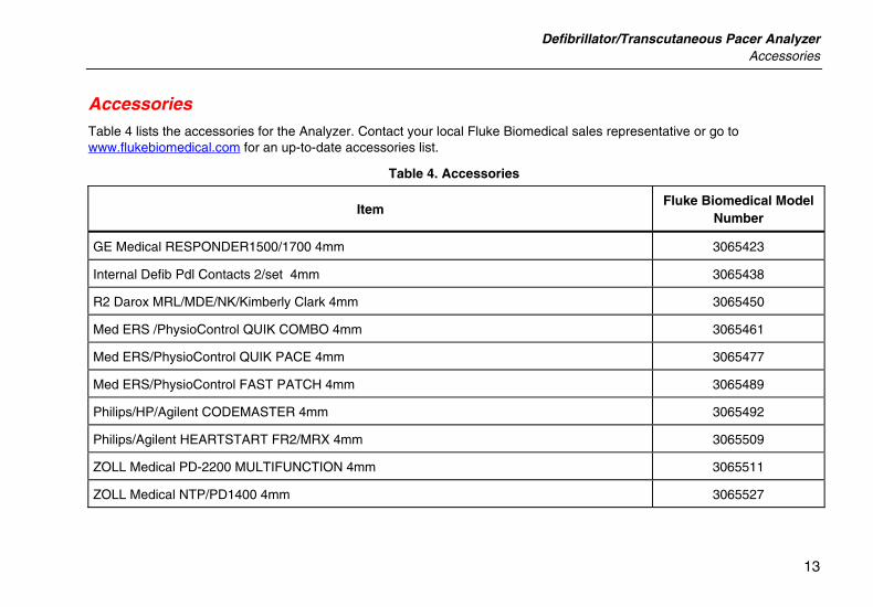
Accessories Table 4 lists the accessories for the Analyzer. Contact your local Fluke Biomedical sales representative or go to www.flukebiomedical.com for an up-to-date accessories list.
Table 4. Accessories
Item Fluke Biomedical Model
Number
GE Medical RESPONDER1500/1700 4mm 3065423
Internal Defib Pdl Contacts 2/set 4mm 3065438
R2 Darox MRL/MDE/NK/Kimberly Clark 4mm 3065450
Med ERS /PhysioControl QUIK COMBO 4mm 3065461
Med ERS/PhysioControl QUIK PACE 4mm 3065477
Med ERS/PhysioControl FAST PATCH 4mm 3065489
Philips/HP/Agilent CODEMASTER 4mm 3065492
Philips/Agilent HEARTSTART FR2/MRX 4mm 3065509
ZOLL Medical PD-2200 MULTIFUNCTION 4mm 3065511
ZOLL Medical NTP/PD1400 4mm 3065527
Impulse 6000D, 7000DP Getting Started Manual
14
Specifications
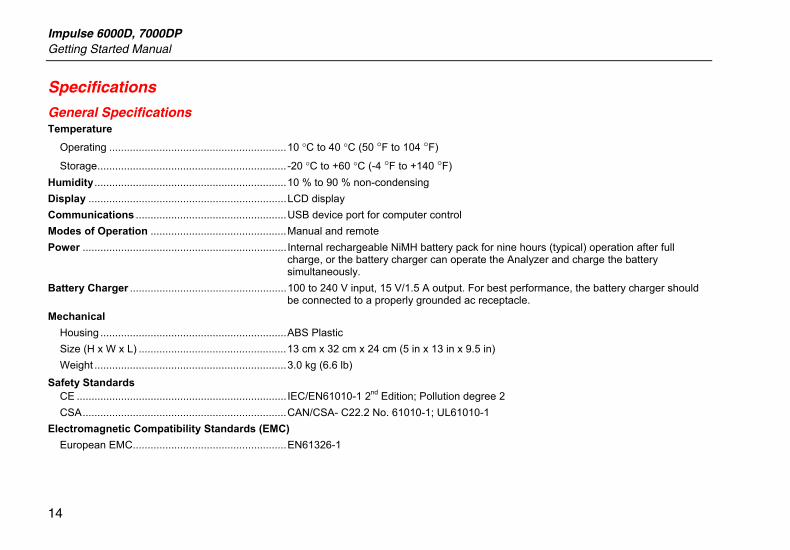
General Specifications Temperature
Operating ............................................................10 °C to 40 °C (50 °F to 104 °F)
Storage................................................................ -20 °C to +60 °C (-4 °F to +140 °F) Humidity.................................................................10 % to 90 % non-condensing Display ...................................................................LCD display Communications ...................................................USB device port for computer control Modes of Operation ..............................................Manual and remote Power ..................................................................... Internal rechargeable NiMH battery pack for nine hours (typical) operation after full
charge, or the battery charger can operate the Analyzer and charge the battery simultaneously.
Battery Charger .....................................................100 to 240 V input, 15 V/1.5 A output. For best performance, the battery charger should be connected to a properly grounded ac receptacle.
Mechanical Housing ...............................................................ABS Plastic Size (H x W x L) ..................................................13 cm x 32 cm x 24 cm (5 in x 13 in x 9.5 in) Weight .................................................................3.0 kg (6.6 lb)
Safety Standards CE ....................................................................... IEC/EN61010-1 2nd Edition; Pollution degree 2 CSA.....................................................................CAN/CSA- C22.2 No. 61010-1; UL61010-1
Electromagnetic Compatibility Standards (EMC) European EMC....................................................EN61326-1
Defibrillator/Transcutaneous Pacer Analyzer Specifications
15
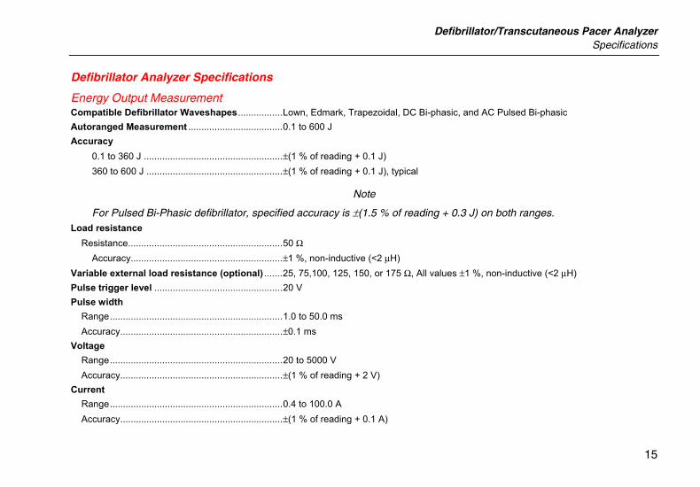
Defibrillator Analyzer Specifications
Energy Output Measurement Compatible Defibrillator Waveshapes.................Lown, Edmark, Trapezoidal, DC Bi-phasic, and AC Pulsed Bi-phasic Autoranged Measurement ....................................0.1 to 600 J Accuracy
0.1 to 360 J .....................................................±(1 % of reading + 0.1 J) 360 to 600 J ....................................................±(1 % of reading + 0.1 J), typical
Note
For Pulsed Bi-Phasic defibrillator, specified accuracy is ±(1.5 % of reading + 0.3 J) on both ranges. Load resistance
Resistance...........................................................50 Ω Accuracy..........................................................±1 %, non-inductive (<2 μH)
Variable external load resistance (optional) .......25, 75,100, 125, 150, or 175 Ω, All values ±1 %, non-inductive (<2 μH) Pulse trigger level .................................................20 V Pulse width
Range..................................................................1.0 to 50.0 ms Accuracy..............................................................±0.1 ms
Voltage Range..................................................................20 to 5000 V Accuracy..............................................................±(1 % of reading + 2 V)
Current Range..................................................................0.4 to 100.0 A Accuracy..............................................................±(1 % of reading + 0.1 A)
Impulse 6000D, 7000DP Getting Started Manual
16
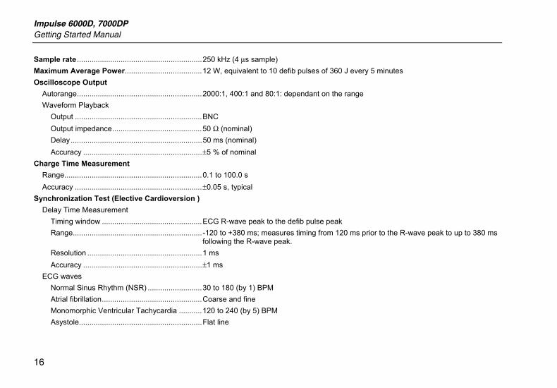
Sample rate ............................................................250 kHz (4 μs sample) Maximum Average Power.....................................12 W, equivalent to 10 defib pulses of 360 J every 5 minutes Oscilloscope Output
Autorange............................................................2000:1, 400:1 and 80:1: dependant on the range Waveform Playback
Output .............................................................BNC Output impedance...........................................50 Ω (nominal) Delay...............................................................50 ms (nominal) Accuracy .........................................................±5 % of nominal
Charge Time Measurement Range..................................................................0.1 to 100.0 s Accuracy .............................................................±0.05 s, typical
Synchronization Test (Elective Cardioversion ) Delay Time Measurement
Timing window ................................................ECG R-wave peak to the defib pulse peak Range.............................................................. -120 to +380 ms; measures timing from 120 ms prior to the R-wave peak to up to 380 ms
following the R-wave peak. Resolution .......................................................1 ms Accuracy .........................................................±1 ms
ECG waves Normal Sinus Rhythm (NSR) ..........................30 to 180 (by 1) BPM Atrial fibrillation................................................Coarse and fine Monomorphic Ventricular Tachycardia ...........120 to 240 (by 5) BPM Asystole...........................................................Flat line
Defibrillator/Transcutaneous Pacer Analyzer Specifications
17
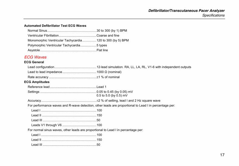
Automated Defibrillator Test ECG Waves Normal Sinus.......................................................30 to 300 (by 1) BPM Ventricular Fibrillation..........................................Coarse and fine Monomorphic Ventricular Tachycardia................120 to 300 (by 5) BPM Polymorphic Ventricular Tachycardia..................5 types Asystole...............................................................Flat line
ECG Waves ECG General
Lead configuration...............................................12-lead simulation. RA, LL, LA, RL, V1-6 with independent outputs Lead to lead impedance......................................1000 Ω (nominal) Rate accuracy .....................................................±1 % of nominal
ECG Amplitudes Reference lead ....................................................Lead 1 Settings ...............................................................0.05 to 0.45 (by 0.05) mV
0.5 to 5.0 (by 0.5) mV Accuracy..............................................................±2 % of setting, lead I and 2 Hz square wave For performance waves and R-wave detection, other leads are proportional to Lead I in percentage per:
Lead I ..............................................................100 Lead II .............................................................150 Lead III ............................................................50 Leads V1 through V6 ......................................100
For normal sinus waves, other leads are proportional to Lead I in percentage per: Lead I ..............................................................100 Lead II .............................................................150 Lead III ............................................................50
Impulse 6000D, 7000DP Getting Started Manual
18
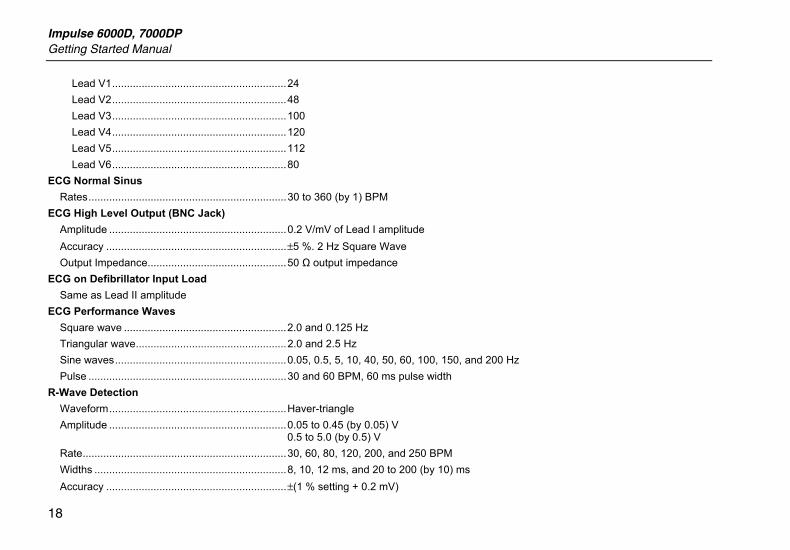
Lead V1...........................................................24 Lead V2...........................................................48 Lead V3...........................................................100 Lead V4...........................................................120 Lead V5...........................................................112 Lead V6...........................................................80
ECG Normal Sinus Rates...................................................................30 to 360 (by 1) BPM
ECG High Level Output (BNC Jack) Amplitude ............................................................0.2 V/mV of Lead I amplitude Accuracy .............................................................±5 %. 2 Hz Square Wave Output Impedance...............................................50 Ω output impedance
ECG on Defibrillator Input Load Same as Lead II amplitude
ECG Performance Waves Square wave .......................................................2.0 and 0.125 Hz Triangular wave...................................................2.0 and 2.5 Hz Sine waves..........................................................0.05, 0.5, 5, 10, 40, 50, 60, 100, 150, and 200 Hz Pulse ...................................................................30 and 60 BPM, 60 ms pulse width
R-Wave Detection Waveform............................................................Haver-triangle Amplitude ............................................................0.05 to 0.45 (by 0.05) V
0.5 to 5.0 (by 0.5) V Rate.....................................................................30, 60, 80, 120, 200, and 250 BPM Widths .................................................................8, 10, 12 ms, and 20 to 200 (by 10) ms Accuracy .............................................................±(1 % setting + 0.2 mV)
Defibrillator/Transcutaneous Pacer Analyzer Specifications
19
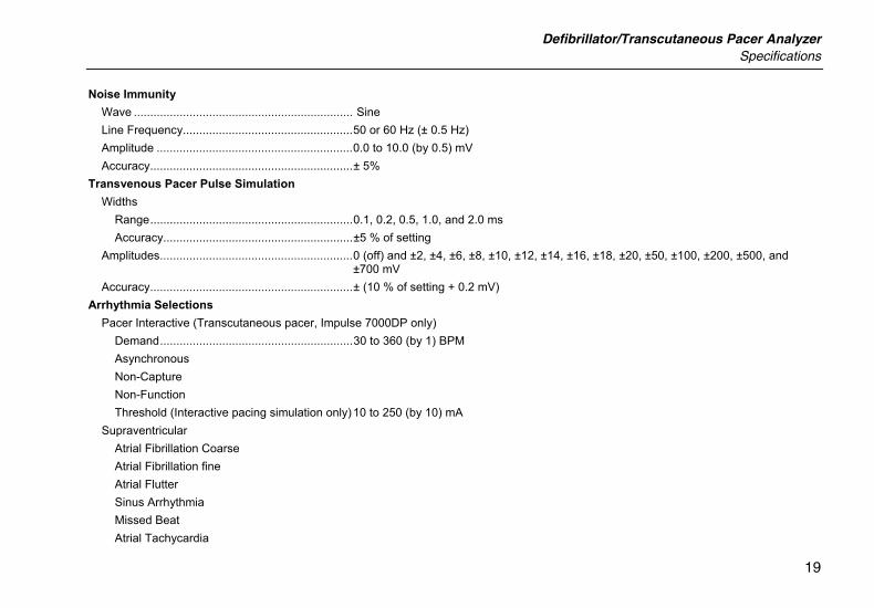
Noise Immunity Wave ................................................................... Sine Line Frequency....................................................50 or 60 Hz (± 0.5 Hz) Amplitude ............................................................0.0 to 10.0 (by 0.5) mV Accuracy..............................................................± 5%
Transvenous Pacer Pulse Simulation Widths
Range..............................................................0.1, 0.2, 0.5, 1.0, and 2.0 ms Accuracy..........................................................±5 % of setting
Amplitudes...........................................................0 (off) and ±2, ±4, ±6, ±8, ±10, ±12, ±14, ±16, ±18, ±20, ±50, ±100, ±200, ±500, and ±700 mV
Accuracy..............................................................± (10 % of setting + 0.2 mV) Arrhythmia Selections
Pacer Interactive (Transcutaneous pacer, Impulse 7000DP only) Demand...........................................................30 to 360 (by 1) BPM Asynchronous Non-Capture Non-Function Threshold (Interactive pacing simulation only)10 to 250 (by 10) mA
Supraventricular Atrial Fibrillation Coarse Atrial Fibrillation fine Atrial Flutter Sinus Arrhythmia Missed Beat Atrial Tachycardia
Impulse 6000D, 7000DP Getting Started Manual
20
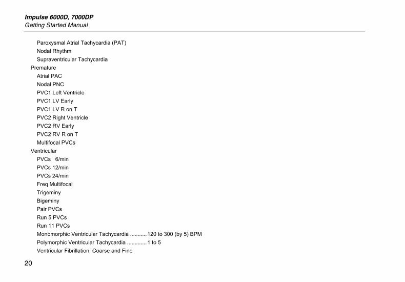
Paroxysmal Atrial Tachycardia (PAT) Nodal Rhythm Supraventricular Tachycardia
Premature Atrial PAC Nodal PNC PVC1 Left Ventricle PVC1 LV Early PVC1 LV R on T PVC2 Right Ventricle PVC2 RV Early PVC2 RV R on T Multifocal PVCs
Ventricular PVCs 6/min PVCs 12/min PVCs 24/min Freq Multifocal Trigeminy Bigeminy Pair PVCs Run 5 PVCs Run 11 PVCs Monomorphic Ventricular Tachycardia ...........120 to 300 (by 5) BPM Polymorphic Ventricular Tachycardia .............1 to 5 Ventricular Fibrillation: Coarse and Fine
Defibrillator/Transcutaneous Pacer Analyzer Specifications
21
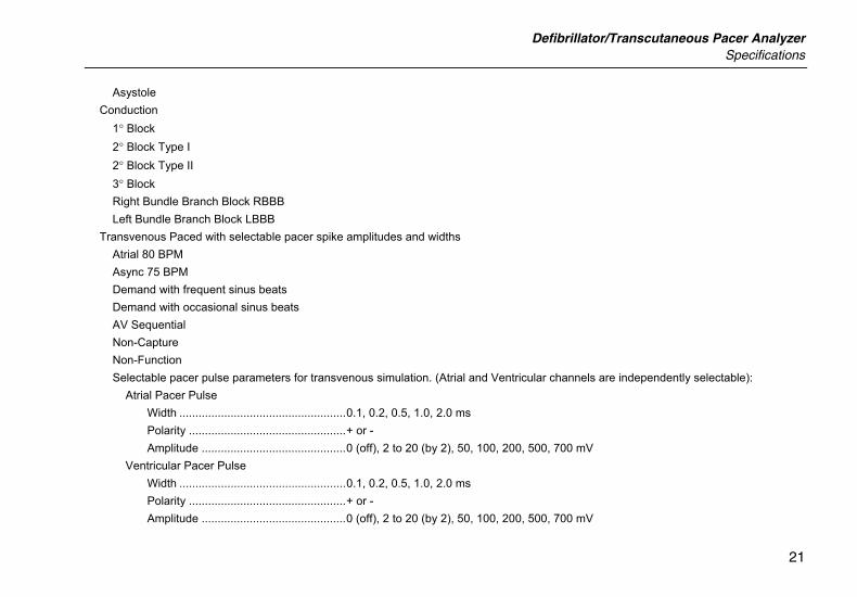
Asystole Conduction
1° Block 2° Block Type I 2° Block Type II 3° Block Right Bundle Branch Block RBBB Left Bundle Branch Block LBBB
Transvenous Paced with selectable pacer spike amplitudes and widths Atrial 80 BPM Async 75 BPM Demand with frequent sinus beats Demand with occasional sinus beats AV Sequential Non-Capture Non-Function Selectable pacer pulse parameters for transvenous simulation. (Atrial and Ventricular channels are independently selectable):
Atrial Pacer Pulse Width ....................................................0.1, 0.2, 0.5, 1.0, 2.0 ms Polarity .................................................+ or - Amplitude .............................................0 (off), 2 to 20 (by 2), 50, 100, 200, 500, 700 mV
Ventricular Pacer Pulse Width ....................................................0.1, 0.2, 0.5, 1.0, 2.0 ms Polarity .................................................+ or - Amplitude .............................................0 (off), 2 to 20 (by 2), 50, 100, 200, 500, 700 mV
Impulse 6000D, 7000DP Getting Started Manual
22
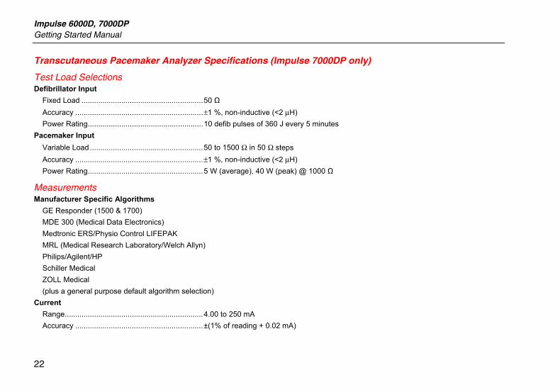
Transcutaneous Pacemaker Analyzer Specifications (Impulse 7000DP only)
Test Load Selections Defibrillator Input
Fixed Load ..........................................................50 Ω Accuracy .............................................................±1 %, non-inductive (<2 μH) Power Rating.......................................................10 defib pulses of 360 J every 5 minutes
Pacemaker Input Variable Load ......................................................50 to 1500 Ω in 50 Ω steps Accuracy .............................................................±1 %, non-inductive (<2 μH) Power Rating.......................................................5 W (average), 40 W (peak) @ 1000 Ω
Measurements Manufacturer Specific Algorithms
GE Responder (1500 & 1700) MDE 300 (Medical Data Electronics) Medtronic ERS/Physio Control LIFEPAK MRL (Medical Research Laboratory/Welch Allyn) Philips/Agilent/HP Schiller Medical ZOLL Medical (plus a general purpose default algorithm selection)
Current Range..................................................................4.00 to 250 mA Accuracy .............................................................±(1% of reading + 0.02 mA)
Defibrillator/Transcutaneous Pacer Analyzer Specifications
23
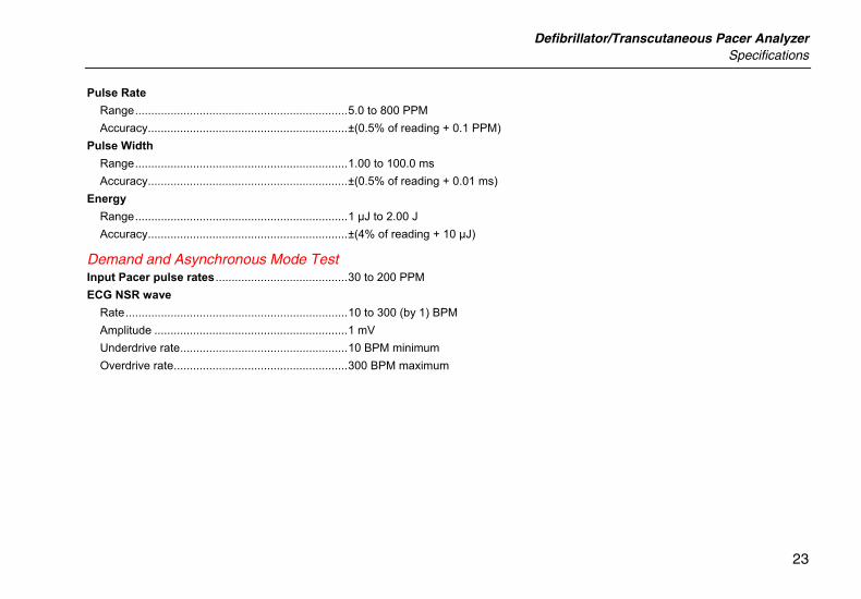
Pulse Rate Range..................................................................5.0 to 800 PPM Accuracy..............................................................±(0.5% of reading + 0.1 PPM)
Pulse Width Range..................................................................1.00 to 100.0 ms Accuracy..............................................................±(0.5% of reading + 0.01 ms)
Energy Range..................................................................1 µJ to 2.00 J Accuracy..............................................................±(4% of reading + 10 µJ)
Demand and Asynchronous Mode Test Input Pacer pulse rates .........................................30 to 200 PPM ECG NSR wave
Rate.....................................................................10 to 300 (by 1) BPM Amplitude ............................................................1 mV Underdrive rate....................................................10 BPM minimum Overdrive rate......................................................300 BPM maximum
Impulse 6000D, 7000DP Getting Started Manual
24
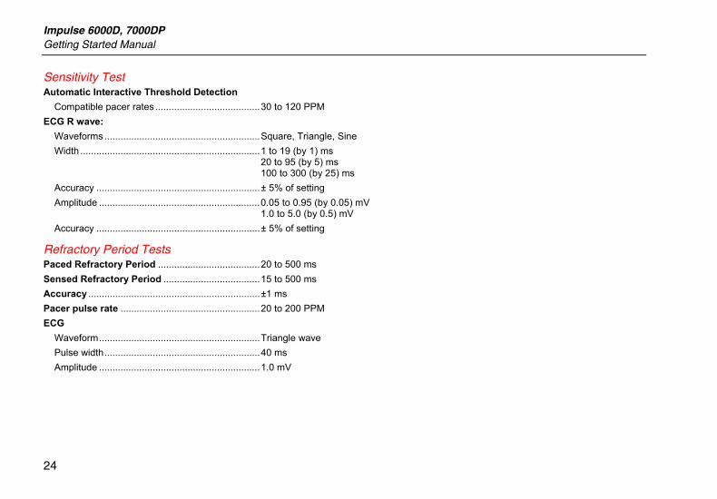
Sensitivity Test Automatic Interactive Threshold Detection
Compatible pacer rates .......................................30 to 120 PPM ECG R wave:
Waveforms ..........................................................Square, Triangle, Sine Width ...................................................................1 to 19 (by 1) ms
20 to 95 (by 5) ms 100 to 300 (by 25) ms
Accuracy .............................................................± 5% of setting Amplitude ............................................................0.05 to 0.95 (by 0.05) mV
1.0 to 5.0 (by 0.5) mV Accuracy .............................................................± 5% of setting
Refractory Period Tests Paced Refractory Period ......................................20 to 500 ms Sensed Refractory Period ....................................15 to 500 ms Accuracy ................................................................±1 ms Pacer pulse rate ....................................................20 to 200 PPM ECG
Waveform............................................................Triangle wave Pulse width..........................................................40 ms Amplitude ............................................................1.0 mV