Embed Size (px)
DESCRIPTION
The outdated camera book
Citation preview
IMS200 SURVEILLANCE SYSTEM USER MANUAL

2
1 PRECAUTIONS
The contents of this manual may change due to product upgrades or other reasons.
We have the right to make changes of the contents without notice.
This user manual is for reference only, subject to available products. This manual may contain inaccurate data
or printing error. We reserves the right to interpret the details of this manual.
3
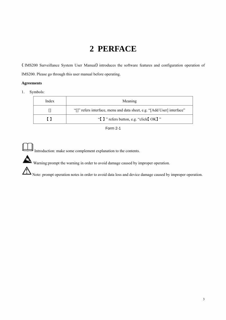
2 PERFACE
《 》IMS200 Surveillance System User Manual introduces the software features and configuration operation of
IMS200. Please go through this user manual before operating.
Agreements
1. Symbols:
Index Meaning
[] “[]” refers interface, menu and data sheet, e.g. “[Add User] interface”
【 】 “【 】 ” refers button, e.g. “click【 OK】 ”
Form 2-1
Introduction: make some complement explanation to the contents.
Warning:prompt the warning in order to avoid damage caused by improper operation.
Note: prompt operation notes in order to avoid data loss and device damage caused by improper operation.
4
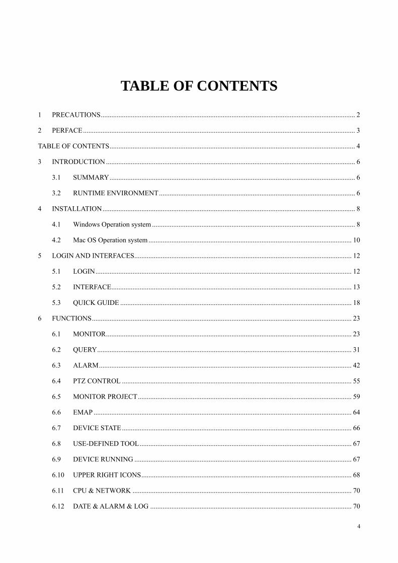
TABLE OF CONTENTS
1 PRECAUTIONS ................................................................................................................................................ 2
2 PERFACE .......................................................................................................................................................... 3
TABLE OF CONTENTS ........................................................................................................................................... 4
3 INTRODUCTION ............................................................................................................................................. 6
3.1 SUMMARY ........................................................................................................................................... 6
3.2 RUNTIME ENVIRONMENT ............................................................................................................... 6
4 INSTALLATION ............................................................................................................................................... 8
4.1 Windows Operation system ................................................................................................................... 8
4.2 Mac OS Operation system ................................................................................................................... 10
5 LOGIN AND INTERFACES ........................................................................................................................... 12
5.1 LOGIN ................................................................................................................................................. 12
5.2 INTERFACE ........................................................................................................................................ 13
5.3 QUICK GUIDE ................................................................................................................................... 18
6 FUNCTIONS ................................................................................................................................................... 23
6.1 MONITOR ........................................................................................................................................... 23
6.2 QUERY ................................................................................................................................................ 31
6.3 ALARM ............................................................................................................................................... 42
6.4 PTZ CONTROL .................................................................................................................................. 55
6.5 MONITOR PROJECT ......................................................................................................................... 59
6.6 EMAP .................................................................................................................................................. 64
6.7 DEVICE STATE .................................................................................................................................. 66
6.8 USE-DEFINED TOOL ........................................................................................................................ 67
6.9 DEVICE RUNNING ........................................................................................................................... 67
6.10 UPPER RIGHT ICONS ....................................................................................................................... 68
6.11 CPU & NETWORK ............................................................................................................................ 70
6.12 DATE & ALARM & LOG .................................................................................................................. 70
5
7 SYSTEM SETTING ........................................................................................................................................ 71
7.1 LOG ..................................................................................................................................................... 71
7.2 LOCAL SET ........................................................................................................................................ 72
7.3 ADMIN CONFIG ................................................................................................................................ 79
7.4 INPUT/OUTPUT ................................................................................................................................. 90
7.5 MODIFY PASSWORD ....................................................................................................................... 91
7.6 LICENSE ............................................................................................................................................. 91
8 APPENDIX A .................................................................................................................................................. 93
8.1 FAQ ..................................................................................................................................................... 93
6
3 INTRODUCTION
3.1 SUMMARY
IMS200 is a professional surveillance system software which support muti-user, multi-window and multilingual
display, voice talk, EMap, alarm and etc. IMS200 is compatible with various access devices. This is a stable, reliable
and easy operation system.
3.2 RUNTIME ENVIRONMENT
� Hardware minimum requirements
� CPU P4/2.0GHz
� Memory 512M
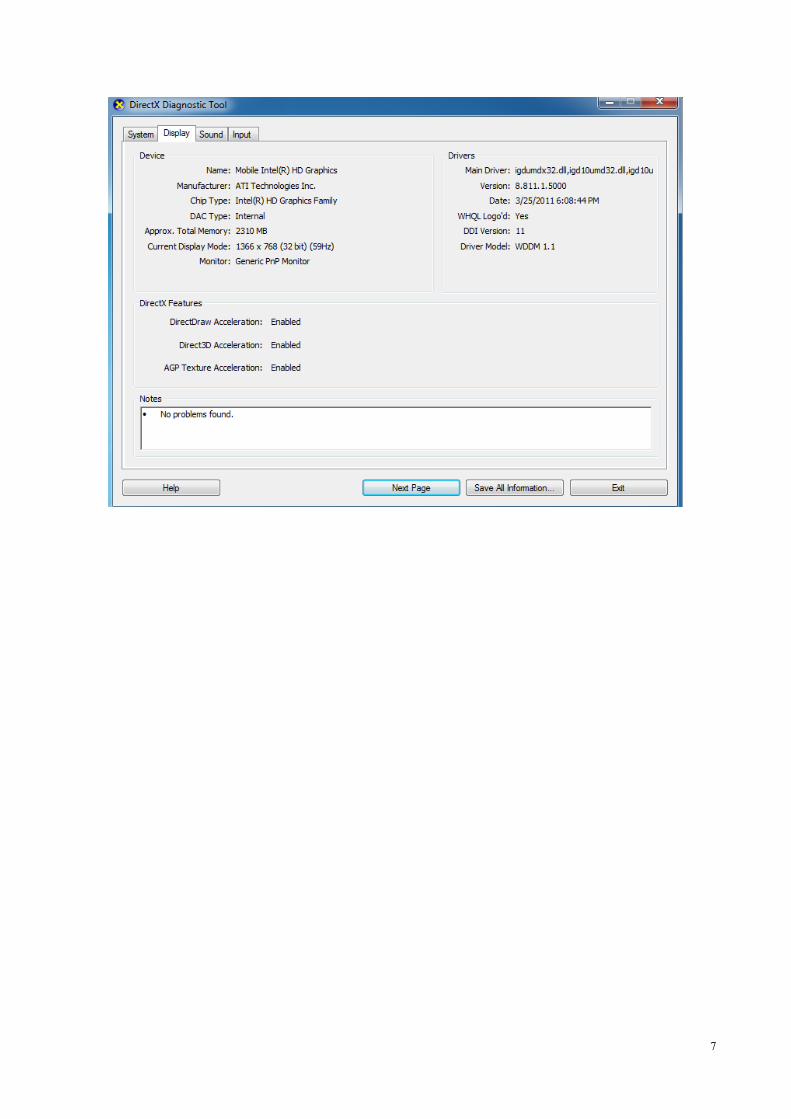
� Resolution 1024*768 and ≥128M memory (support DirectX 8.0 and higher grade)
� Hard Disk 300M free space
� Network transmission 10/100Mbps Ethernet, consistent with TCP/IP or UDP/IP protocal
� Software minimum requirements
� Operation system: Windows XP SP2, Windows 2000, Windows 2003, Windows Vista, win7(run by
“Administrator” in Vista and win7),Mac OS
� Graphics drive installed
Introduction: enable “DirectX”, set the “hardware speed up” to ‘high’
7
8
4 INSTALLATION
4.1 Windows Operation system
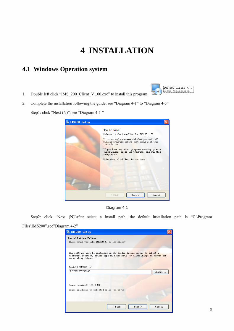
1. Double left click “IMS_200_Client_V1.00.exe” to install this program.
2. Complete the installation following the guide, see “Diagram 4-1” to “Diagram 4-5”
Step1: click “Next (N)”, see “Diagram 4-1 ”
Diagram 4-1
Step2: click “Next (N)”after select a install path, the default installation path is “C:\Program
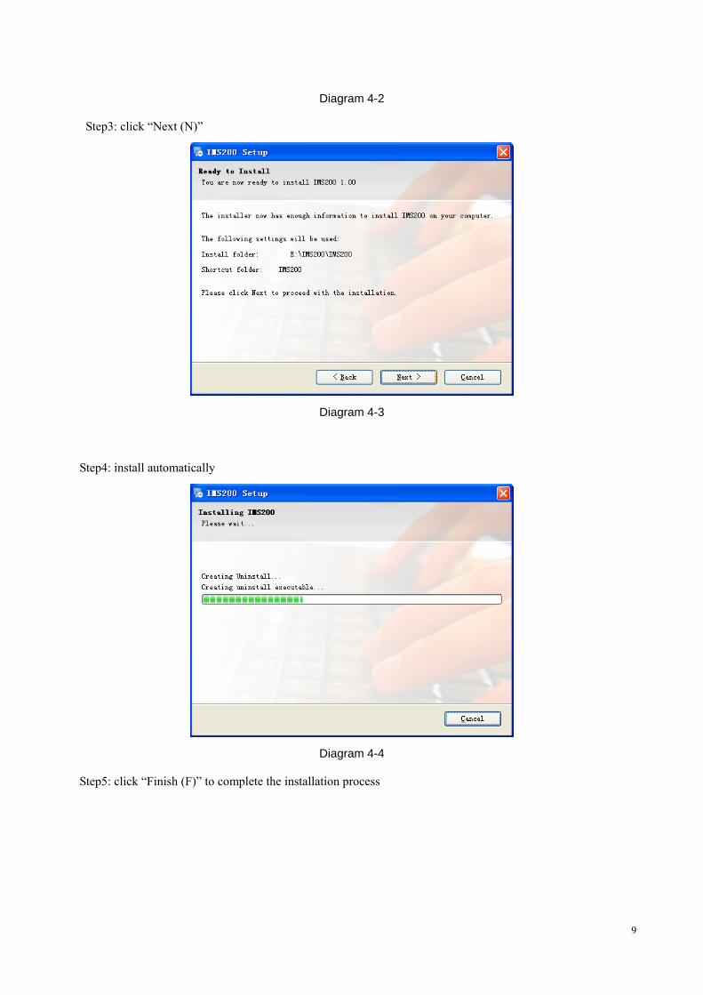
Files\IMS200”.see”Diagram 4-2”
9
Diagram 4-2
Step3: click “Next (N)”
Diagram 4-3
Step4: install automatically
Diagram 4-4
Step5: click “Finish (F)” to complete the installation process
10
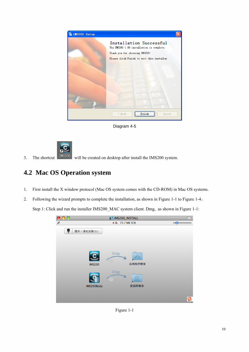
Diagram 4-5
3. The shortcut will be created on desktop after install the IMS200 system.
4.2 Mac OS Operation system
1. First install the X window protocol (Mac OS system comes with the CD-ROM) in Mac OS systems.
2. Following the wizard prompts to complete the installation, as shown in Figure 1-1 to Figure 1-4。
Step 1: Click and run the installer IMS200_MAC system client. Dmg, as shown in Figure 1-1:
Figure 1-1
11
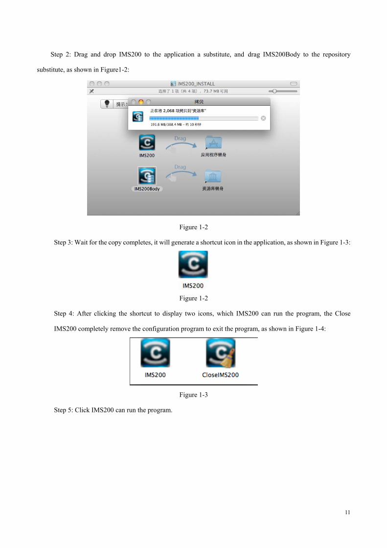
Step 2: Drag and drop IMS200 to the application a substitute, and drag IMS200Body to the repository
substitute, as shown in Figure1-2:
Figure 1-2
Step 3: Wait for the copy completes, it will generate a shortcut icon in the application, as shown in Figure 1-3:
Figure 1-2
Step 4: After clicking the shortcut to display two icons, which IMS200 can run the program, the Close
IMS200 completely remove the configuration program to exit the program, as shown in Figure 1-4:
Figure 1-3
Step 5: Click IMS200 can run the program.
12
5 LOGIN AND INTERFACES
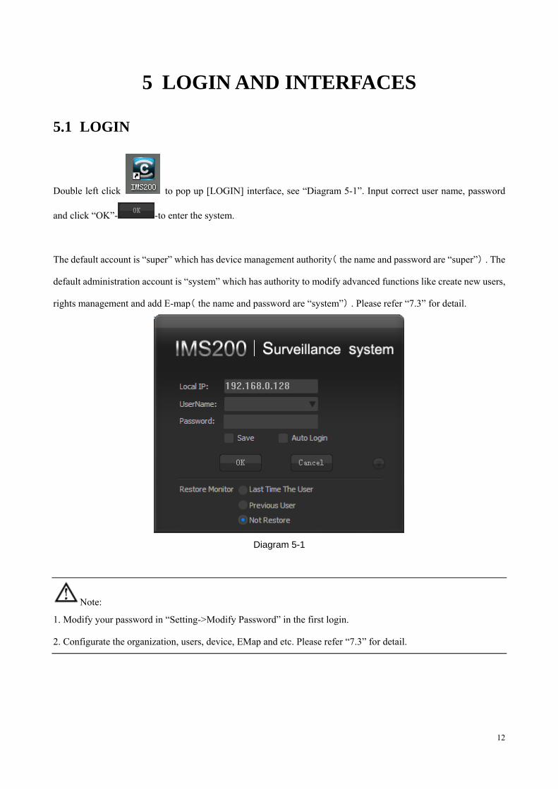
5.1 LOGIN
Double left click to pop up [LOGIN] interface, see “Diagram 5-1”. Input correct user name, password
and click “OK”- -to enter the system.
The default account is “super” which has device management authority( )the name and password are “super” . The
default administration account is “system” which has authority to modify advanced functions like create new users,
rights management and add E-map( )the name and password are “system” . Please refer “7.3” for detail.
Diagram 5-1
Note:
1. Modify your password in “Setting->Modify Password” in the first login.
2. Configurate the organization, users, device, EMap and etc. Please refer “7.3” for detail.
13
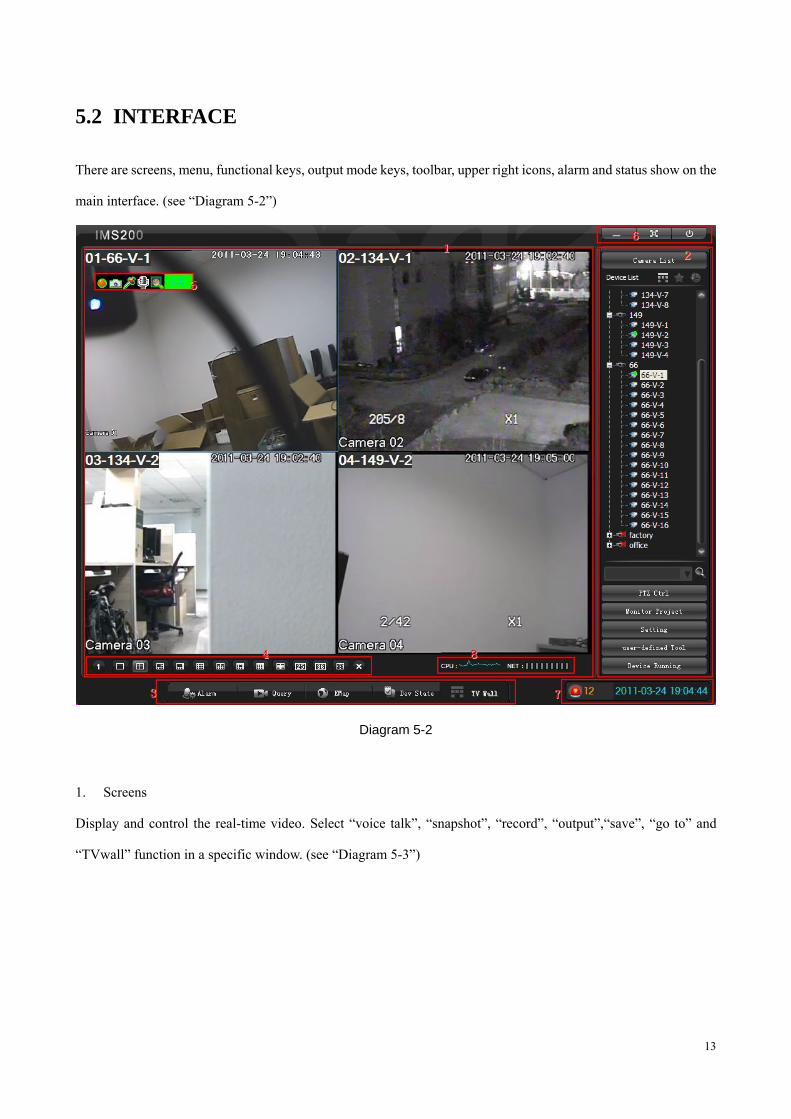
5.2 INTERFACE
There are screens, menu, functional keys, output mode keys, toolbar, upper right icons, alarm and status show on the
main interface. (see “Diagram 5-2”)
Diagram 5-2
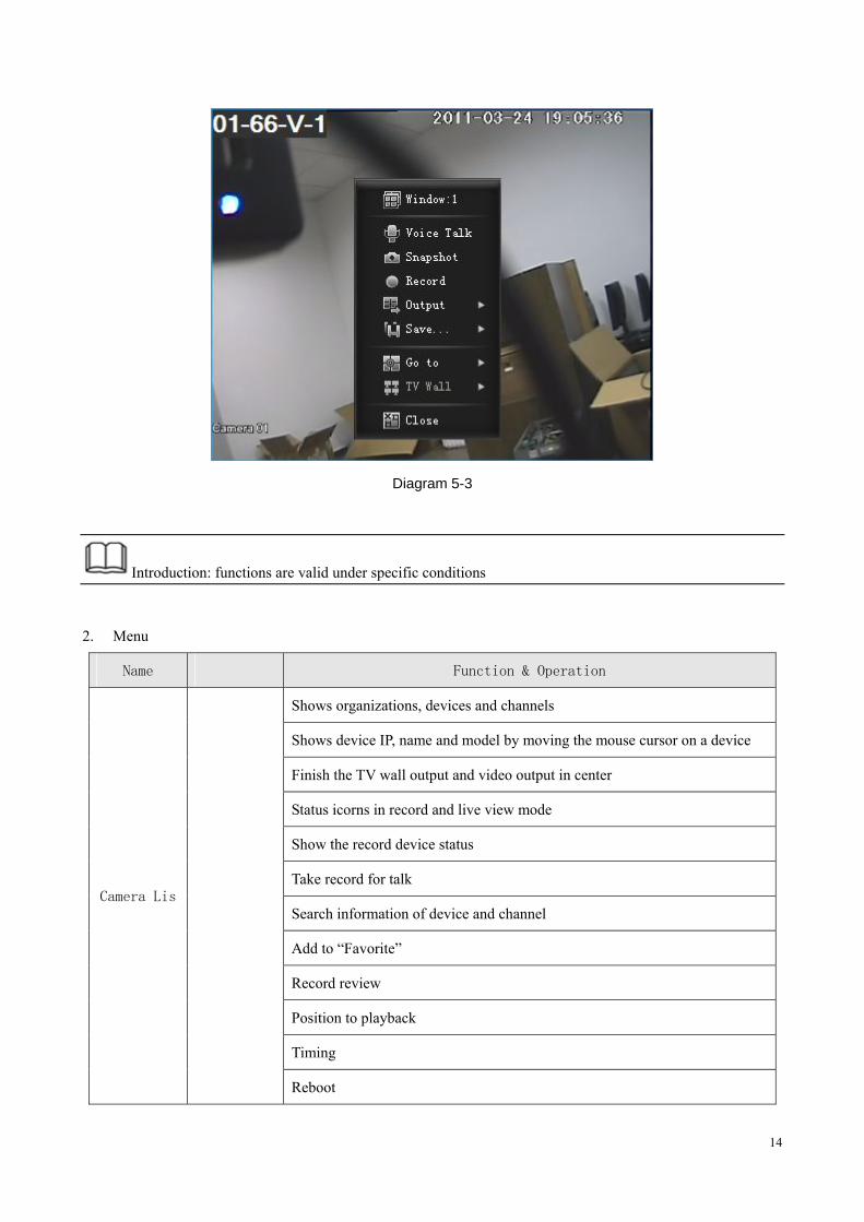
1. Screens
Display and control the real-time video. Select “voice talk”, “snapshot”, “record”, “output”,“save”, “go to” and
“TVwall” function in a specific window. (see “Diagram 5-3”)
14
Diagram 5-3
Introduction: functions are valid under specific conditions
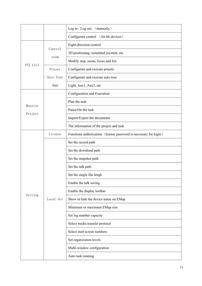
2. Menu
Name Function & Operation
Camera Lis
Shows organizations, devices and channels
Shows device IP, name and model by moving the mouse cursor on a device
Finish the TV wall output and video output in center
Status icorns in record and live view mode
Show the record device status
Take record for talk
Search information of device and channel
Add to “Favorite”
Record review
Position to playback
Timing
Reboot
15
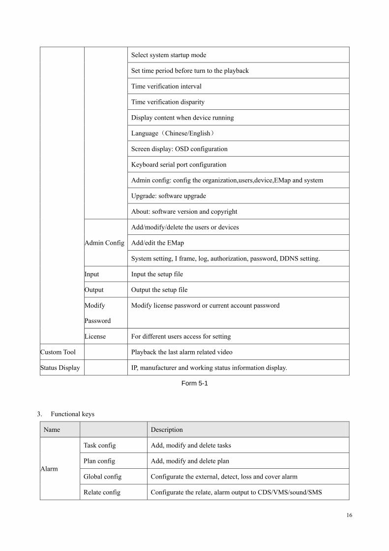
Log in / Log out (manually)
Configurate control (for hk devices)
PTZ Ctrl
Control
zoom
Eight-direction control
3D positioning, simulated joystick, etc
Modify step, zoom, focus and Iris
Preset
Auto Tour
Aux
Configurate and execute presets
Configurate and execute auto tour
Light, Aux1, Aux2, etc
Monitor
Project
Configuration and Execution
Plan the task
Pause/On the task
Import/Export the documents
The information of the project and task
Setting
License Functions authorization(license password is necessary for login)
Local Set
Set the record path
Set the download path
Set the snapshot path
Set the talk path
Set the single file lengh
Enable the talk saving
Enable the display toolbar
Show or hide the device name on EMap
Minimum or maximum EMap size
Set log number capacity
Select media transfer protocal
Select start screen numbers
Set organization levels
Multi-window configuration
Auto task running
16
Select system startup mode
Set time period before turn to the playback
Time verification interval
Time verification disparity
Display content when device running
Language(Chinese/English)
Screen display: OSD configuration
Keyboard serial port configuration
Admin config: config the organization,users,device,EMap and system
Upgrade: software upgrade
About: software version and copyright
Admin Config
Add/modify/delete the users or devices
Add/edit the EMap
System setting, I frame, log, authorization, password, DDNS setting.
Input Input the setup file
Output Output the setup file
Modify
Password
Modify license password or current account password
License For different users access for setting
Custom Tool Playback the last alarm related video
Status Display IP, manufacturer and working status information display.
Form 5-1
3. Functional keys
Name Description
Alarm
Task config Add, modify and delete tasks
Plan config Add, modify and delete plan
Global config Configurate the external, detect, loss and cover alarm
Relate config Configurate the relate, alarm output to CDS/VMS/sound/SMS
17
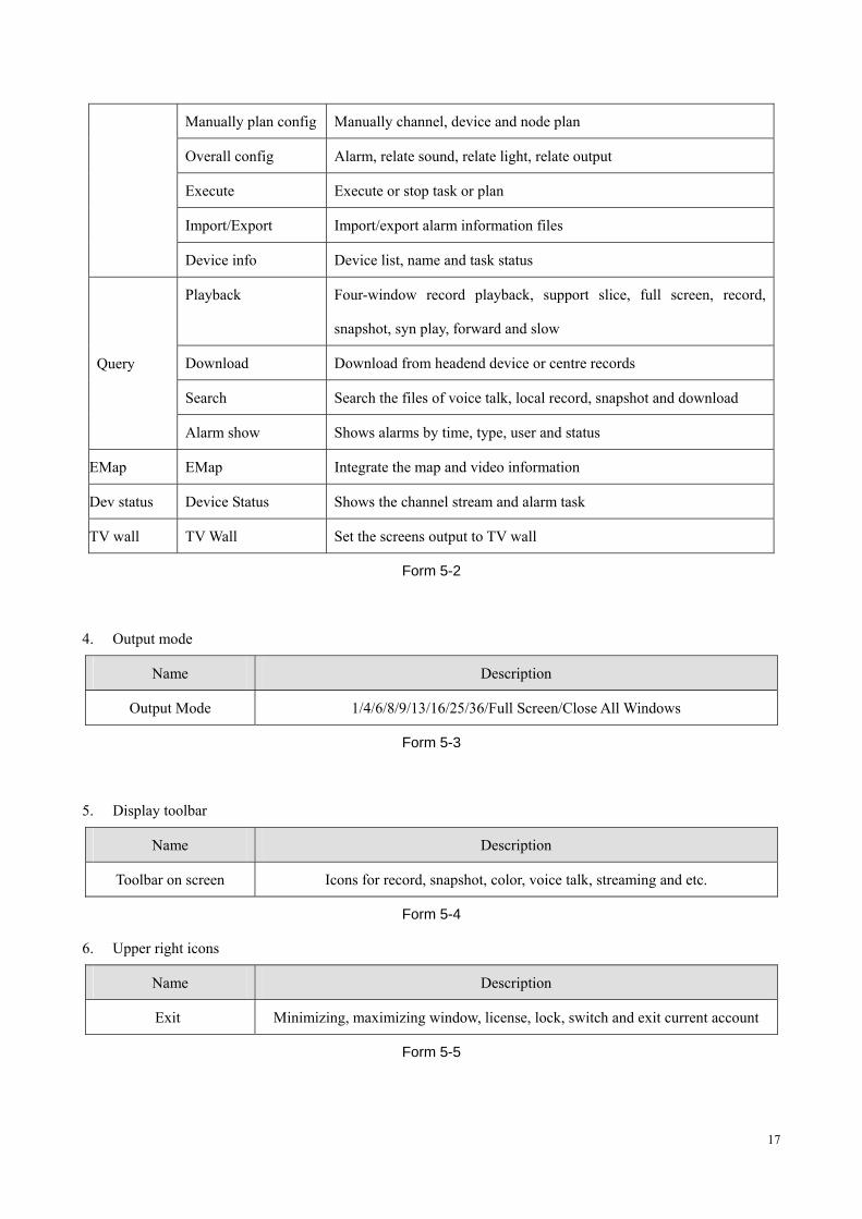
Manually plan config Manually channel, device and node plan
Overall config Alarm, relate sound, relate light, relate output
Execute Execute or stop task or plan
Import/Export Import/export alarm information files
Device info Device list, name and task status
Query
Playback Four-window record playback, support slice, full screen, record,
snapshot, syn play, forward and slow
Download Download from headend device or centre records
Search Search the files of voice talk, local record, snapshot and download
Alarm show Shows alarms by time, type, user and status
EMap EMap Integrate the map and video information
Dev status Device Status Shows the channel stream and alarm task
TV wall TV Wall Set the screens output to TV wall
Form 5-2
4. Output mode
Name Description
Output Mode 1/4/6/8/9/13/16/25/36/Full Screen/Close All Windows
Form 5-3
5. Display toolbar
Name Description
Toolbar on screen Icons for record, snapshot, color, voice talk, streaming and etc.
Form 5-4
6. Upper right icons
Name Description
Exit Minimizing, maximizing window, license, lock, switch and exit current account
Form 5-5
18
7. Alarm & Date
Name Description
Shortcut zoom Pop up system log and alarm interface by clicking the time and alarm icon
Form 5-6
8. Status
Name Description
Status CPU and network running status
Form 5-7
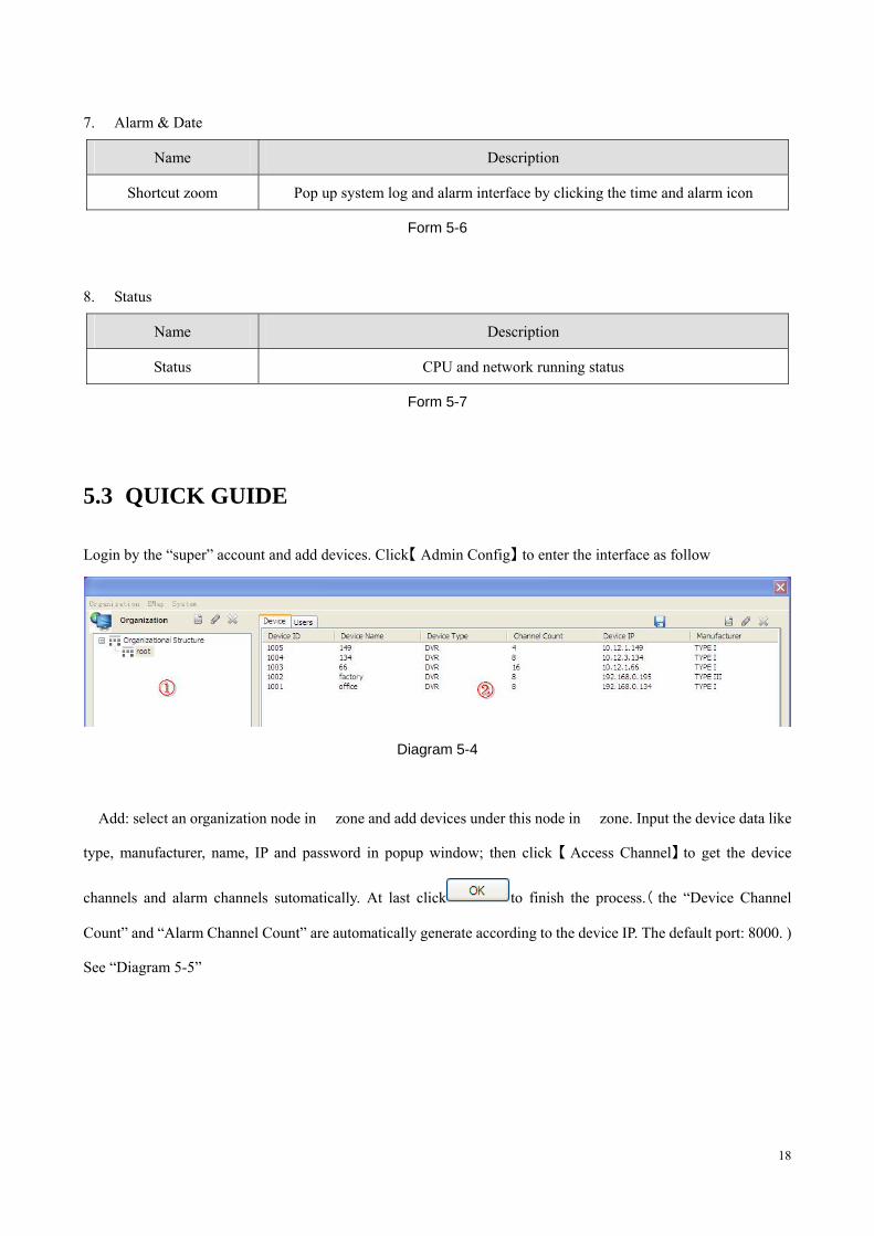
5.3 QUICK GUIDE
Login by the “super” account and add devices. Click【 】Admin Config to enter the interface as follow
Diagram 5-4
� Add: select an organization node in � zone and add devices under this node in � zone. Input the device data like
type, manufacturer, name, IP and password in popup window; then click 【 】Access Channel to get the device
channels and alarm channels sutomatically. At last click to finish the process.( the “Device Channel
Count” and “Alarm Channel Count” are automatically generate according to the device IP. The default port: 8000. )
See “Diagram 5-5”
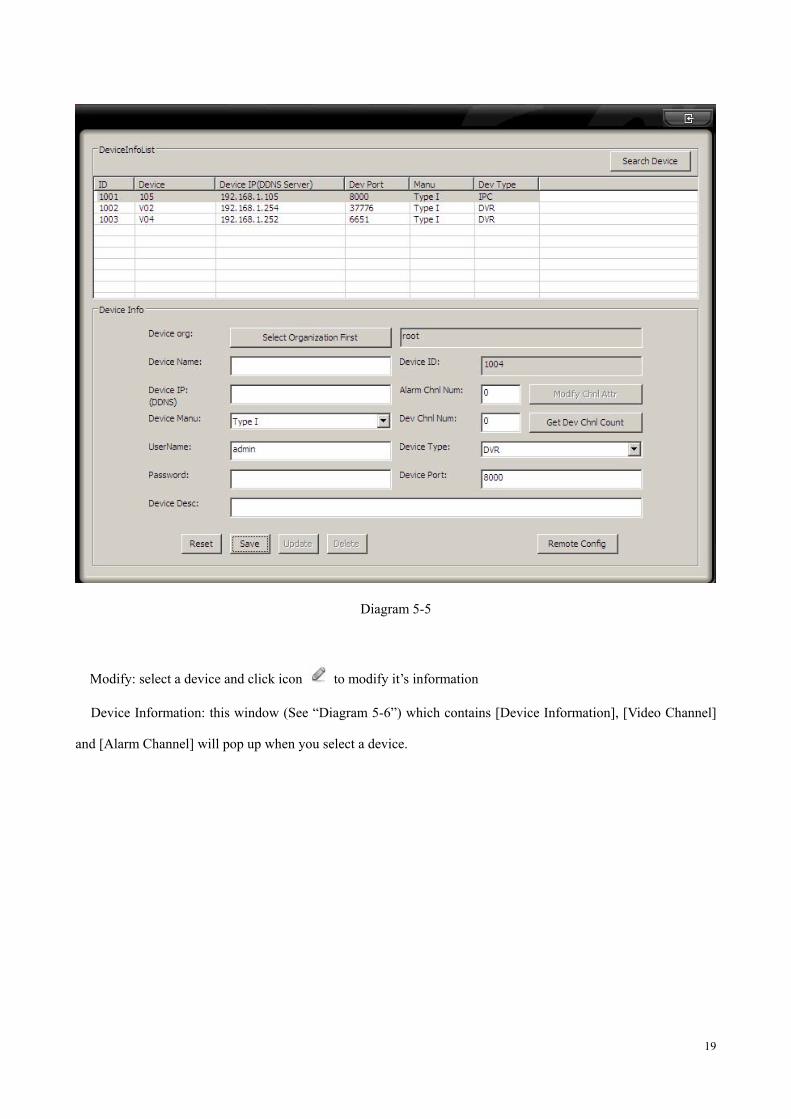
19
Diagram 5-5
� Modify: select a device and click icon to modify it’s information
� Device Information: this window (See “Diagram 5-6”) which contains [Device Information], [Video Channel]
and [Alarm Channel] will pop up when you select a device.
20
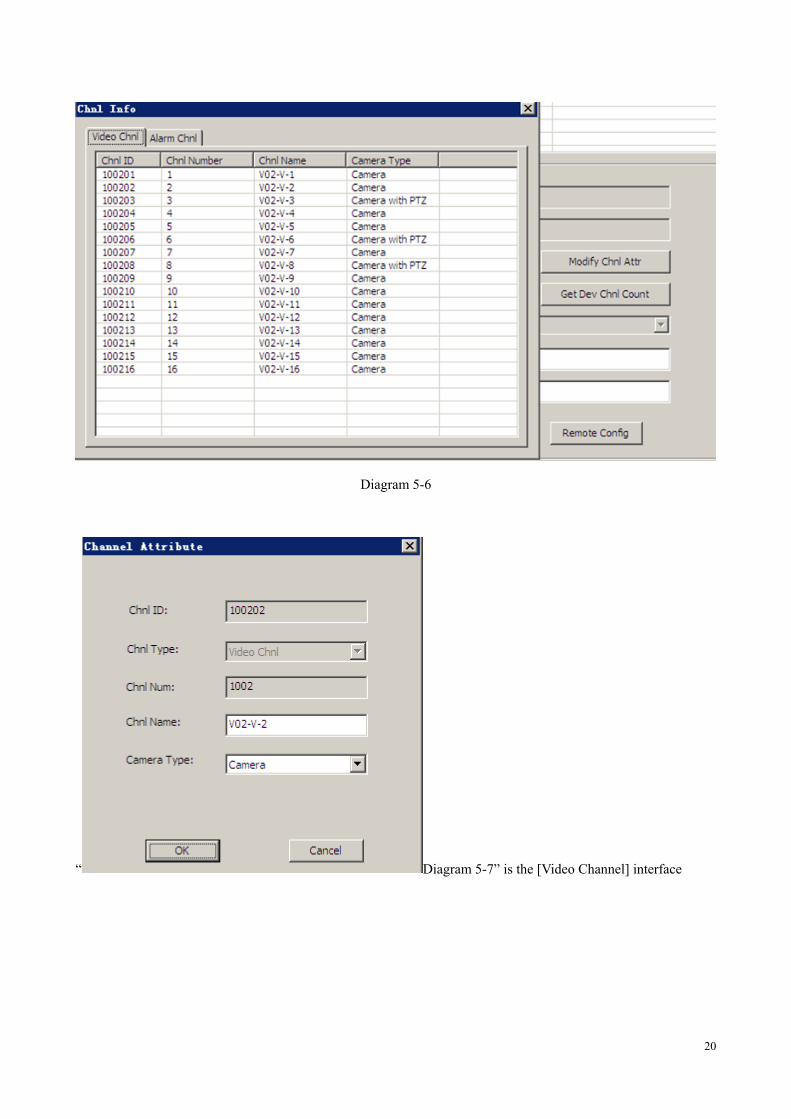
Diagram 5-6
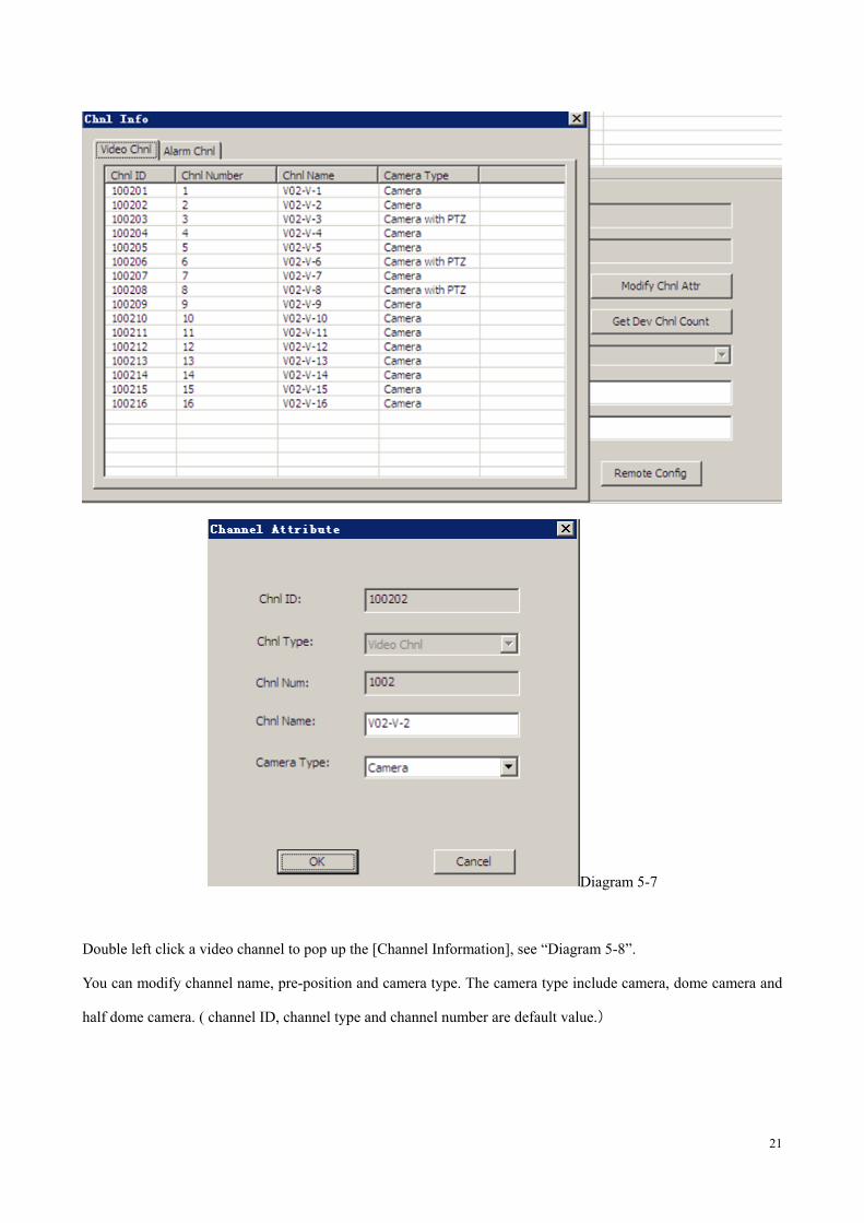
“ Diagram 5-7” is the [Video Channel] interface
21
Diagram 5-7
Double left click a video channel to pop up the [Channel Information], see “Diagram 5-8”.
You can modify channel name, pre-position and camera type. The camera type include camera, dome camera and
half dome camera. ( channel ID, channel type and channel number are default value.)
22
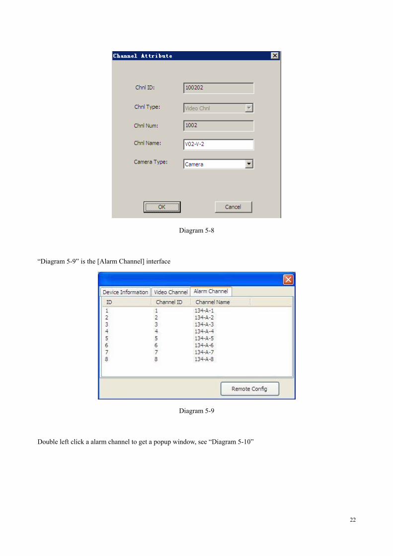
Diagram 5-8
“Diagram 5-9” is the [Alarm Channel] interface
Diagram 5-9
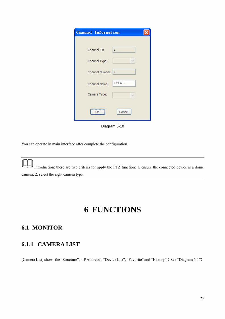
Double left click a alarm channel to get a popup window, see “Diagram 5-10”
23
Diagram 5-10
You can operate in main interface after complete the configuration.
Introduction: there are two criteria for apply the PTZ function: 1. ensure the connected device is a dome
camera; 2. select the right camera type.
6 FUNCTIONS
6.1 MONITOR
6.1.1 CAMERA LIST
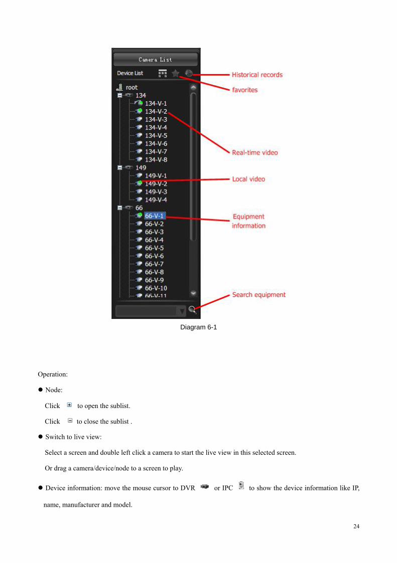
[Camera List] shows the “Structure”, “IP Address”, “Device List”, “Favorite” and “History”.( See “Diagram 6-1”)
24
Diagram 6-1
Operation:
Node:
Click to open the sublist.
Click to close the sublist .
Switch to live view:
Select a screen and double left click a camera to start the live view in this selected screen.
Or drag a camera/device/node to a screen to play.
Device information: move the mouse cursor to DVR or IPC to show the device information like IP,
name, manufacturer and model.
25
Start talk: select a camera and enable the voice talk in context menu, click again to stop talk.
Add to “Favorite”: select a node/camera/channel and add to favorite in context menu.
Playback interface position: Select a camera and position it to the playback interface by context menu.
Set “Playback before”: Setting—>Local Set—>Other
EMap position: select a camera and position it to the EMap by context menu
Search: input device name or IP to search
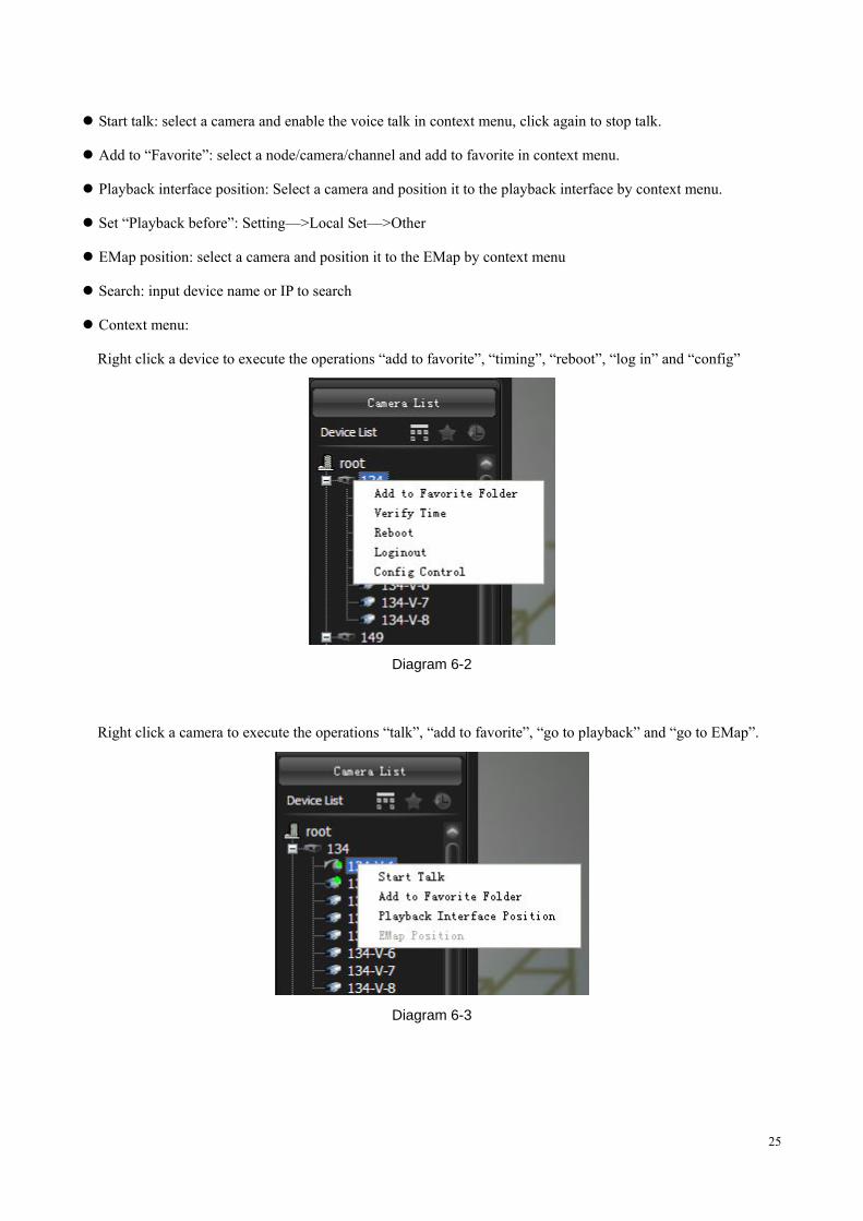
Context menu:
Right click a device to execute the operations “add to favorite”, “timing”, “reboot”, “log in” and “config”
Diagram 6-2
Right click a camera to execute the operations “talk”, “add to favorite”, “go to playback” and “go to EMap”.
Diagram 6-3
26
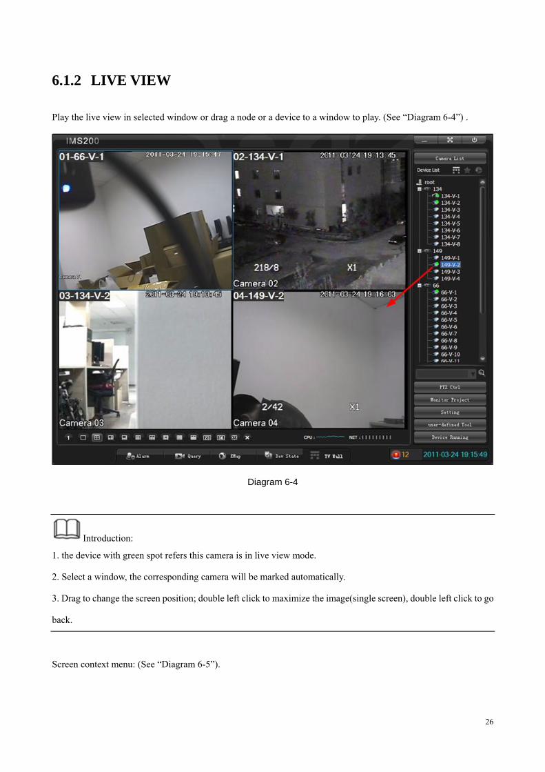
6.1.2 LIVE VIEW
Play the live view in selected window or drag a node or a device to a window to play. (See “Diagram 6-4”) .
Diagram 6-4
Introduction:
1. the device with green spot refers this camera is in live view mode.
2. Select a window, the corresponding camera will be marked automatically.
3. Drag to change the screen position; double left click to maximize the image(single screen), double left click to go
back.
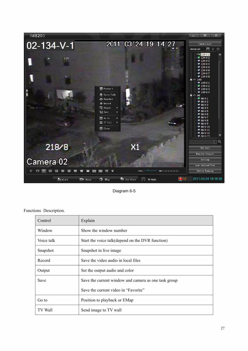
Screen context menu: (See “Diagram 6-5”).
27
Diagram 6-5
Functions Description.
Control Explain
Window Show the window number
Voice talk Start the voice talk(depend on the DVR function)
Snapshot Snapshot in live image
Record Save the video audio in local files
Output Set the output audio and color
Save Save the current window and camera as one task group
Save the current video in “Favorite”
Go to Position to playback or EMap
TV Wall Send image to TV wall
28
Close Close the selected window
Form 6-1
6.1.3 RECORD
Click the【 】Record in context menu to start recording, click again to stop the operation. Set record path in
[Setting]—>[Local Set]—>[Record].
Introduction : : in recording, : device, : channel
6.1.4 SNAPSHOT
Click【 】Snapshot in context menu to save one single image of the video.
Path: Setting —> Local Set —> Record.
The default path: C:\Program Files\IMS200\PIC.
Save format: .bmp.
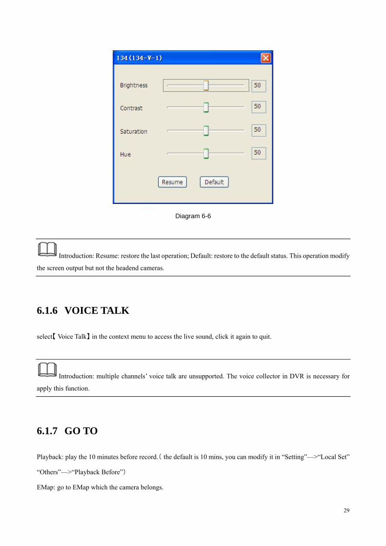
6.1.5 COLOR
You can modify brightness, contrast, saturation and hue in screen [context menu] —>[Output]—>[Color]. (see
“Diagram 6-6”)
29
Diagram 6-6
Introduction: Resume: restore the last operation; Default: restore to the default status. This operation modify
the screen output but not the headend cameras.
6.1.6 VOICE TALK
select【 】Voice Talk in the context menu to access the live sound, click it again to quit.
Introduction: multiple channels’ voice talk are unsupported. The voice collector in DVR is necessary for
apply this function.
6.1.7 GO TO
Playback: play the 10 minutes before record.( the default is 10 mins, you can modify it in “Setting”—>“Local Set”
“Others”—>“Playback Before”)
EMap: go to EMap which the camera belongs.
30
6.1.8 TV WALL
TV wall is supported, contact with the technical support staff for further information.
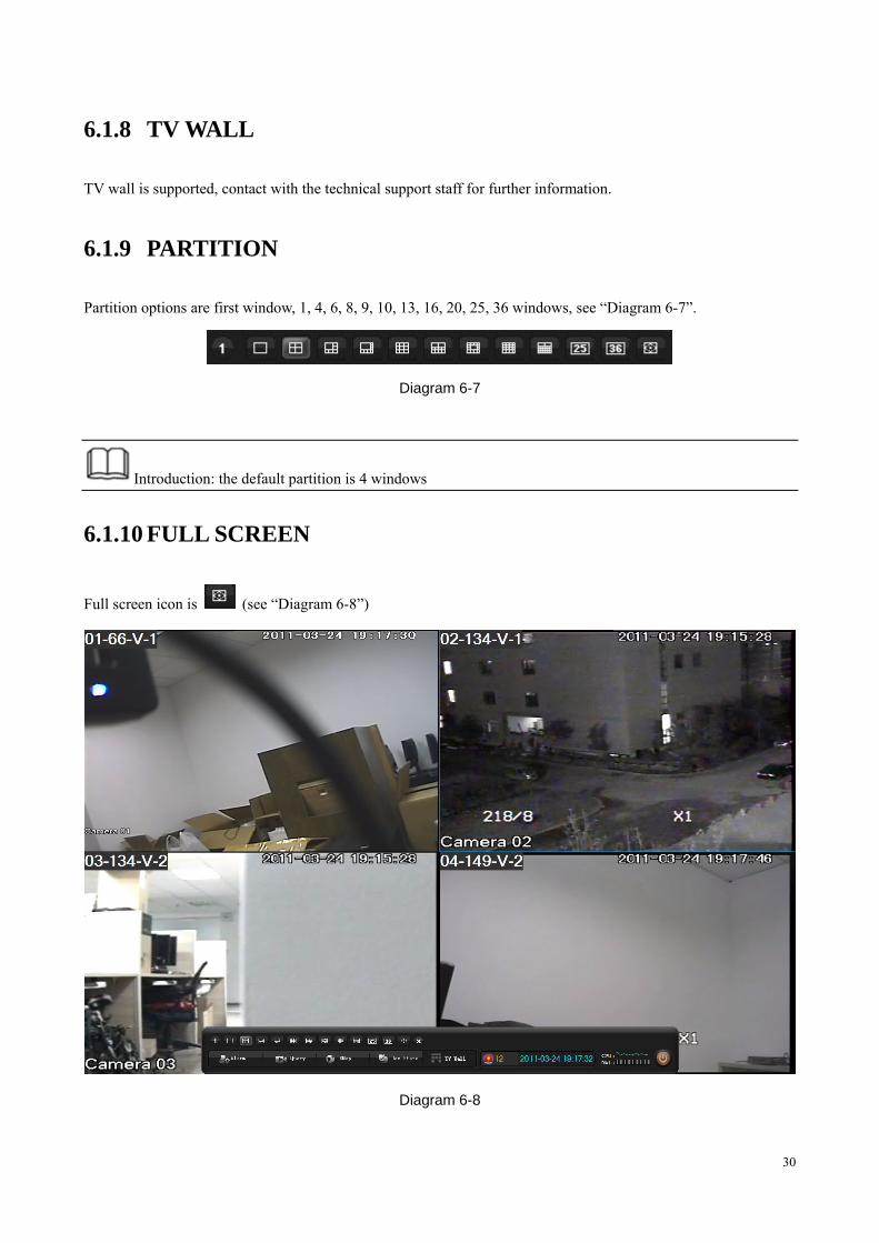
6.1.9 PARTITION
Partition options are first window, 1, 4, 6, 8, 9, 10, 13, 16, 20, 25, 36 windows, see “Diagram 6-7”.
Diagram 6-7
Introduction: the default partition is 4 windows
6.1.10 FULL SCREEN
Full screen icon is (see “Diagram 6-8”)
Diagram 6-8
31
Introduction:
1. the right side toolbar pop up as cursor move into this zoom, hided as cursor move out.
2. the bottom toolbar pop up as cursor move into this zoom, hided as cursor move out.
3. click “Esc” to exit.
6.1.11 CLOSE ALL WINDOW
Click to close all screens.
6.2 QUERY
“Query” include “Playback”, “Download”, “Search” and “Alarm Show”.
6.2.1 PLAYBACK
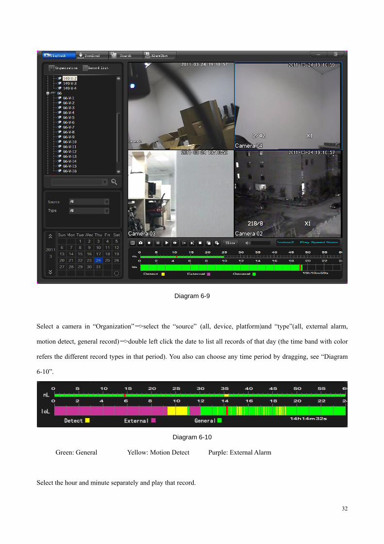
Click【 】Query to pop up the [Playback] interface (see “Diagram 6-9”) .
32
Diagram 6-9
Select a camera in “Organization”->select the “source” (all, device, platform)and “type”(all, external alarm,
motion detect, general record)->double left click the date to list all records of that day (the time band with color
refers the different record types in that period). You also can choose any time period by dragging, see “Diagram
6-10”.
Diagram 6-10
Green: General Yellow: Motion Detect Purple: External Alarm
Select the hour and minute separately and play that record.
33
Click to synchronize four windows’ record time with the selected specific window
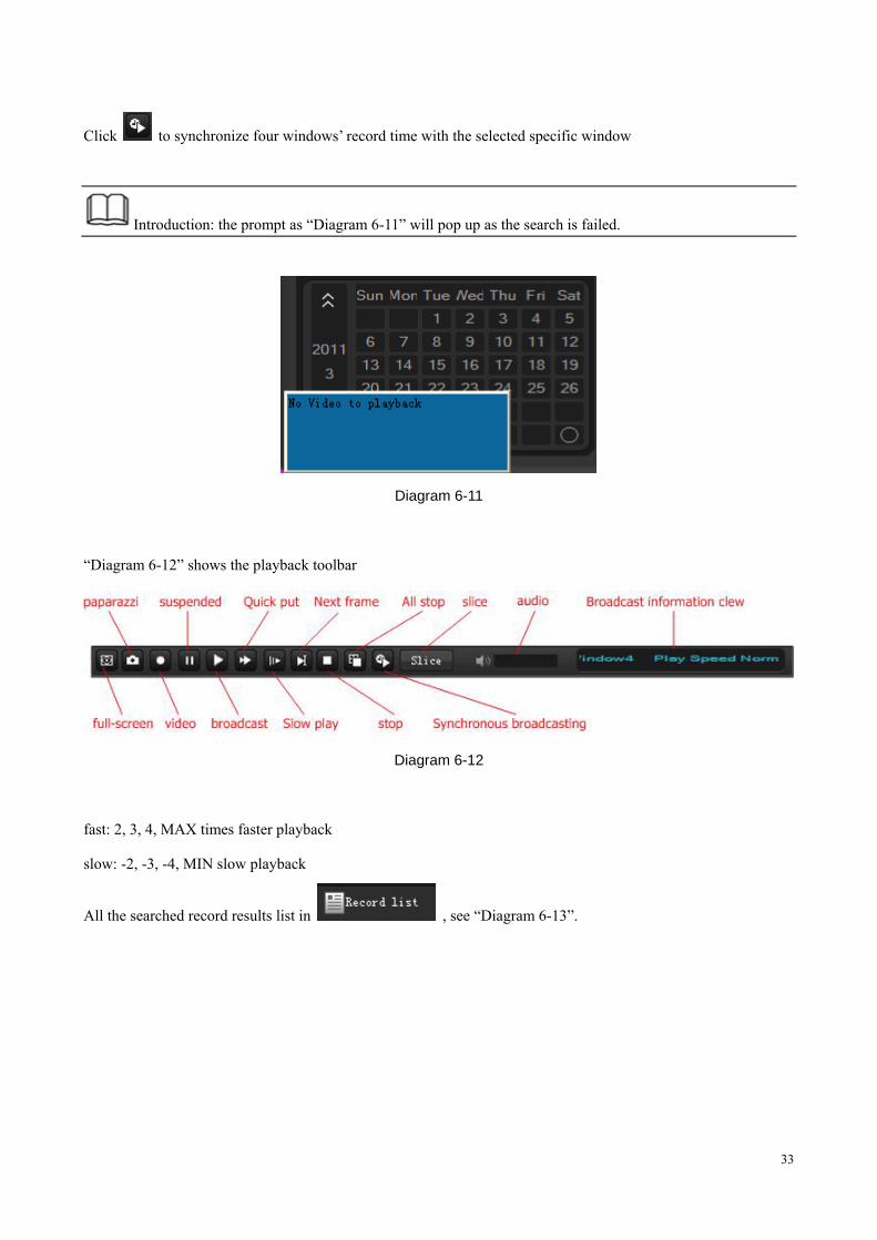
Introduction: the prompt as “Diagram 6-11” will pop up as the search is failed.
Diagram 6-11
“Diagram 6-12” shows the playback toolbar
Diagram 6-12
fast: 2, 3, 4, MAX times faster playback
slow: -2, -3, -4, MIN slow playback
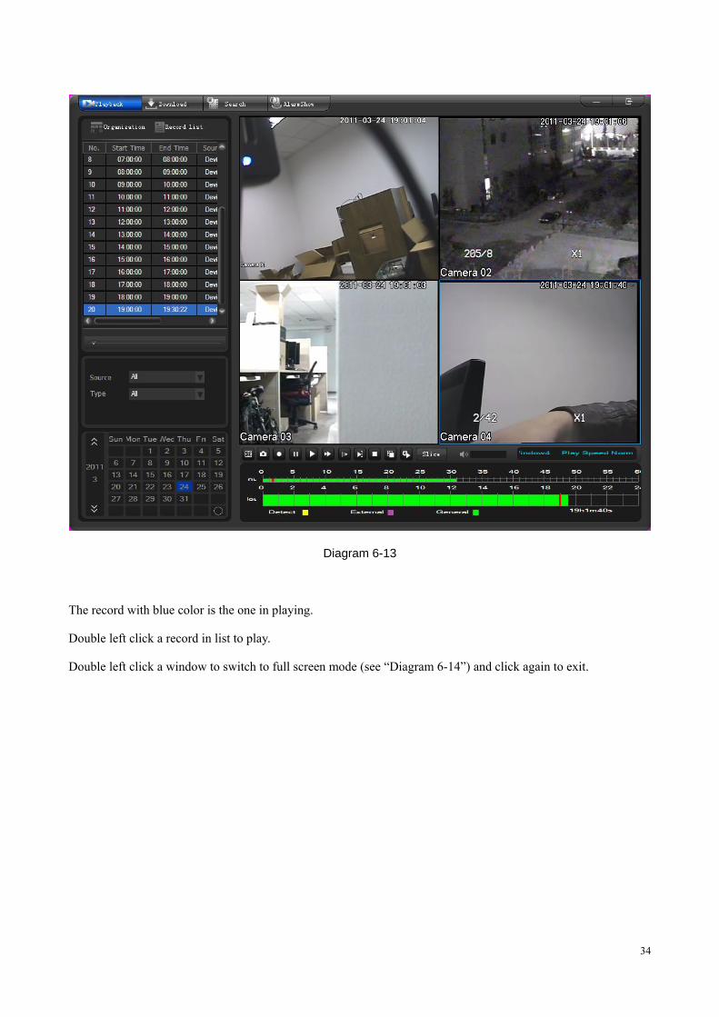
All the searched record results list in , see “Diagram 6-13”.
34
Diagram 6-13
The record with blue color is the one in playing.
Double left click a record in list to play.
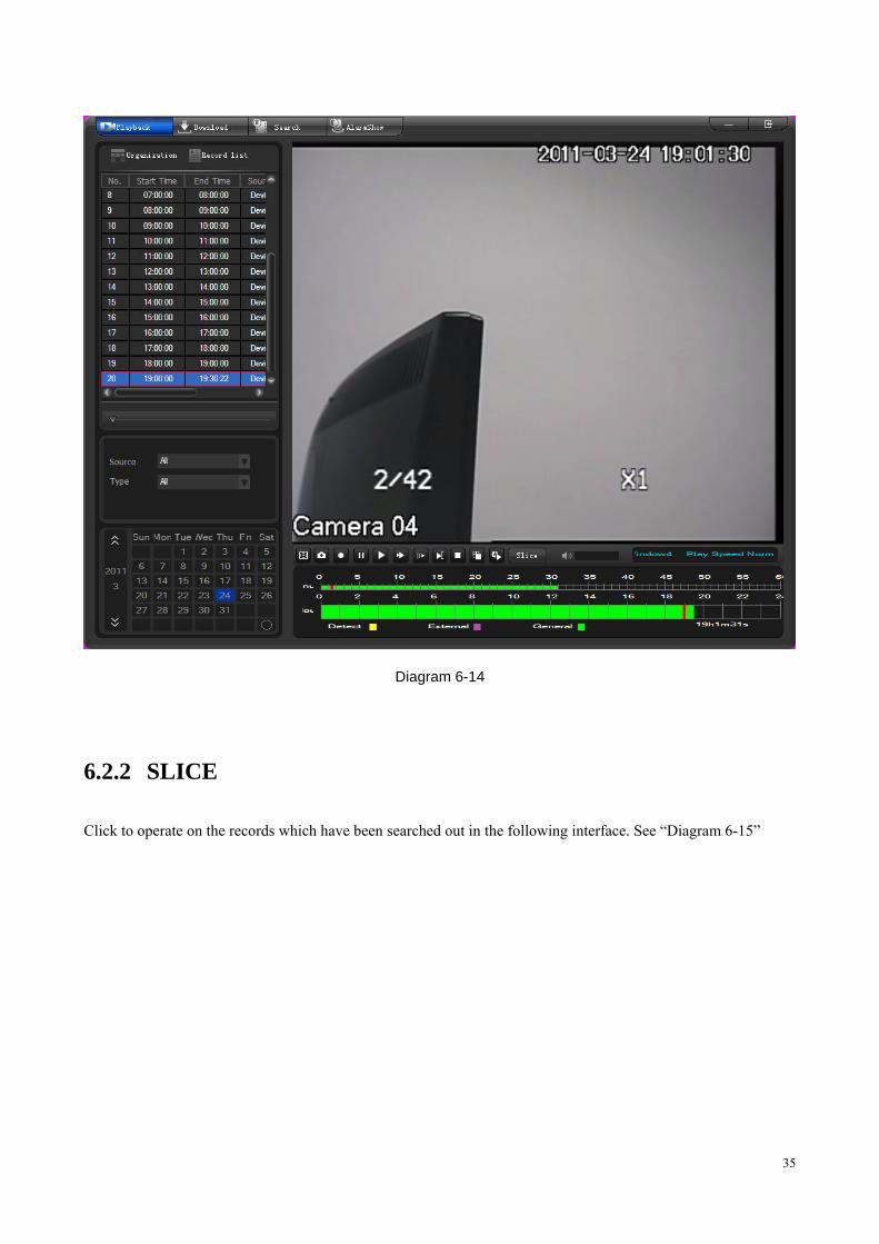
Double left click a window to switch to full screen mode (see “Diagram 6-14”) and click again to exit.
35
Diagram 6-14
6.2.2 SLICE
Click to operate on the records which have been searched out in the following interface. See “Diagram 6-15”
36
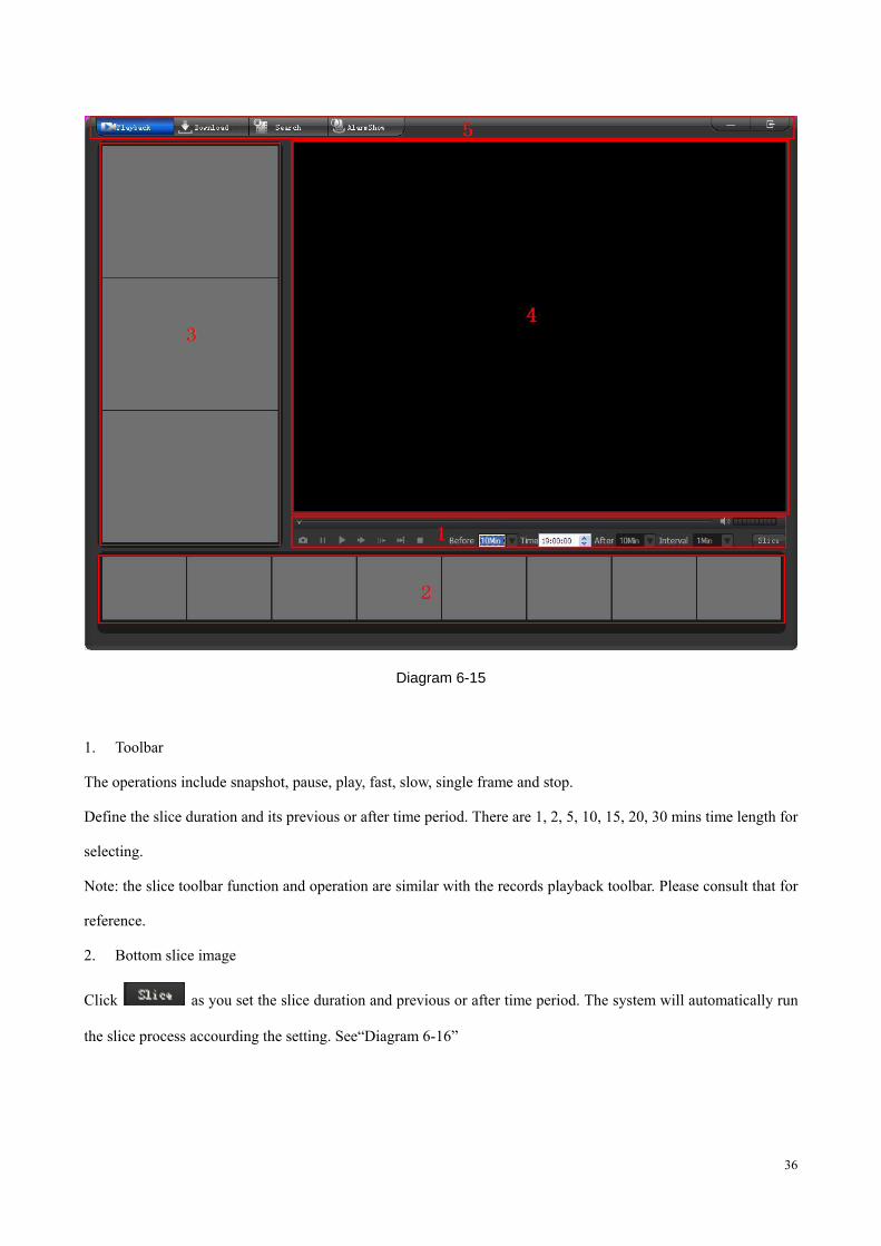
Diagram 6-15
1. Toolbar
The operations include snapshot, pause, play, fast, slow, single frame and stop.
Define the slice duration and its previous or after time period. There are 1, 2, 5, 10, 15, 20, 30 mins time length for
selecting.
Note: the slice toolbar function and operation are similar with the records playback toolbar. Please consult that for
reference.
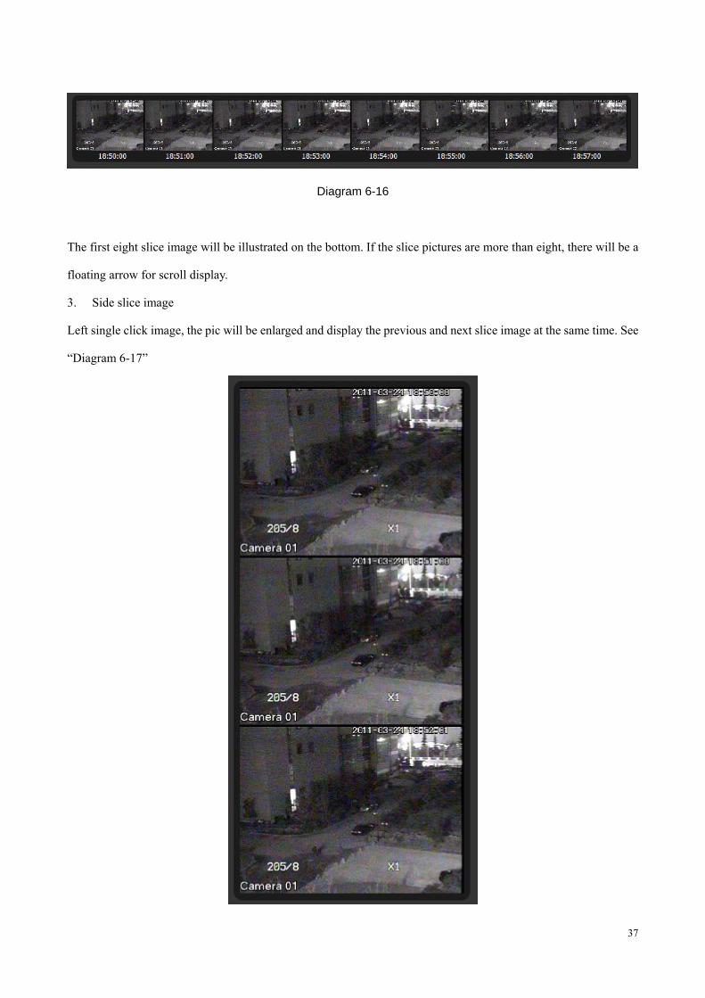
2. Bottom slice image
Click as you set the slice duration and previous or after time period. The system will automatically run
the slice process accourding the setting. See“Diagram 6-16”
37
Diagram 6-16
The first eight slice image will be illustrated on the bottom. If the slice pictures are more than eight, there will be a
floating arrow for scroll display.
3. Side slice image
Left single click image, the pic will be enlarged and display the previous and next slice image at the same time. See
“Diagram 6-17”
38
Diagram 6-17
The selected image is displayed in the middle, the other two image are put as the time sequence.
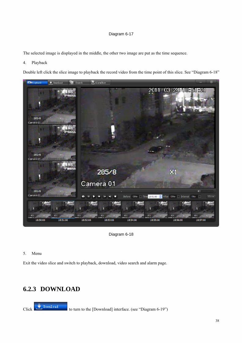
4. Playback
Double left click the slice image to playback the record video from the time point of this slice. See “Diagram 6-18”
Diagram 6-18
5. Menu
Exit the video slice and switch to playback, download, video search and alarm page.
6.2.3 DOWNLOAD
Click to turn to the [Download] interface. (see “Diagram 6-19”)
39
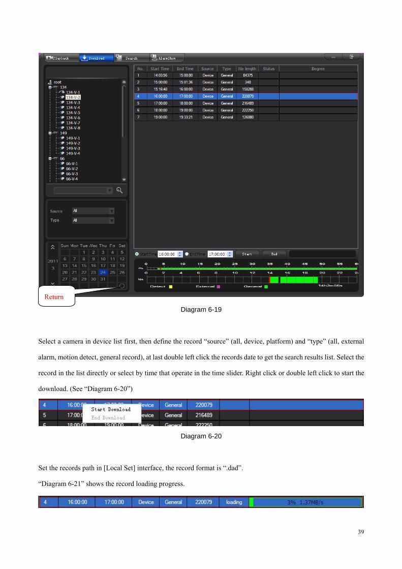
Diagram 6-19
Select a camera in device list first, then define the record “source” (all, device, platform) and “type” (all, external
alarm, motion detect, general record), at last double left click the records date to get the search results list. Select the
record in the list directly or select by time that operate in the time slider. Right click or double left click to start the
download. (See “Diagram 6-20”)
Diagram 6-20
Set the records path in [Local Set] interface, the record format is “.dad”.
“Diagram 6-21” shows the record loading progress.
Return
40
Diagram 6-21
Input the start and end time, click to download all the records in this period. Click to stop download. (See
“Diagram 6-22”)
Diagram 6-22
Introduction: you can not download and playback the same channel records at the same time. The system
will stop the playback automatically when you start downloading.
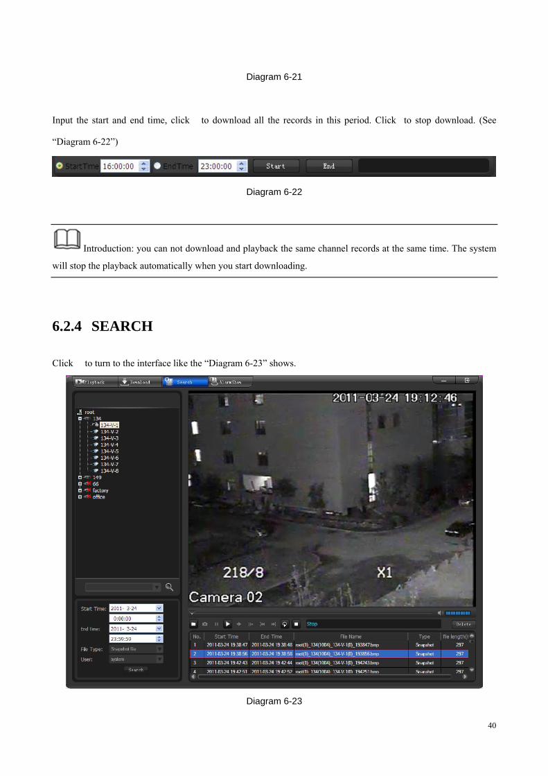
6.2.4 SEARCH
Click to turn to the interface like the “Diagram 6-23” shows.
Diagram 6-23
41
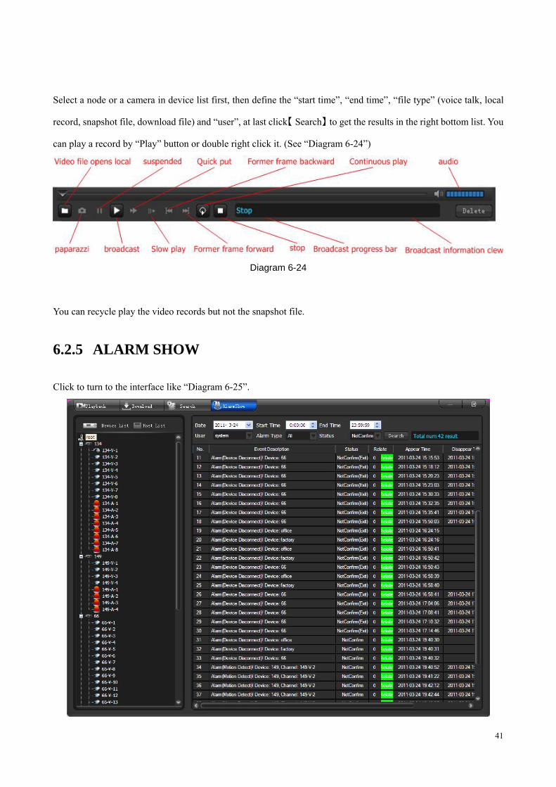
Select a node or a camera in device list first, then define the “start time”, “end time”, “file type” (voice talk, local
record, snapshot file, download file) and “user”, at last click【 】Search to get the results in the right bottom list. You
can play a record by “Play” button or double right click it. (See “Diagram 6-24”)
Diagram 6-24
You can recycle play the video records but not the snapshot file.
6.2.5 ALARM SHOW
Click to turn to the interface like “Diagram 6-25”.
42
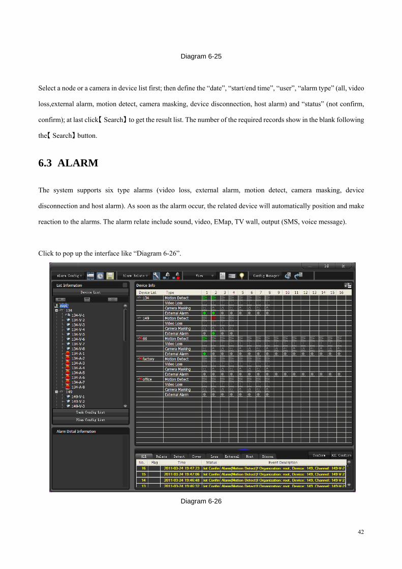
Diagram 6-25
Select a node or a camera in device list first; then define the “date”, “start/end time”, “user”, “alarm type” (all, video
loss,external alarm, motion detect, camera masking, device disconnection, host alarm) and “status” (not confirm,
confirm); at last click【 】Search to get the result list. The number of the required records show in the blank following
the【 】Search button.
6.3 ALARM
The system supports six type alarms (video loss, external alarm, motion detect, camera masking, device
disconnection and host alarm). As soon as the alarm occur, the related device will automatically position and make
reaction to the alarms. The alarm relate include sound, video, EMap, TV wall, output (SMS, voice message).
Click to pop up the interface like “Diagram 6-26”.
Diagram 6-26
43
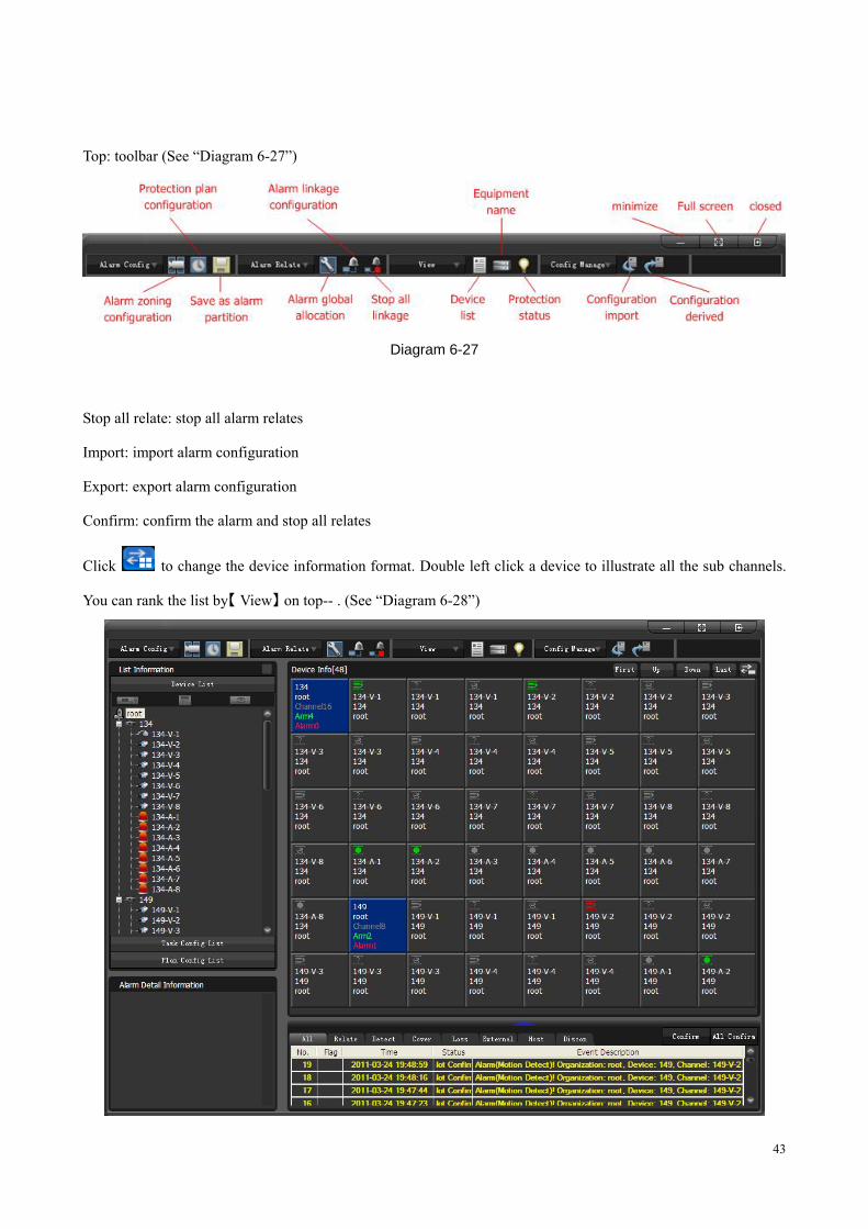
Top: toolbar (See “Diagram 6-27”)
Diagram 6-27
Stop all relate: stop all alarm relates
Import: import alarm configuration
Export: export alarm configuration
Confirm: confirm the alarm and stop all relates
Click to change the device information format. Double left click a device to illustrate all the sub channels.
You can rank the list by【 View】 on top-- . (See “Diagram 6-28”)
44
Diagram 6-28
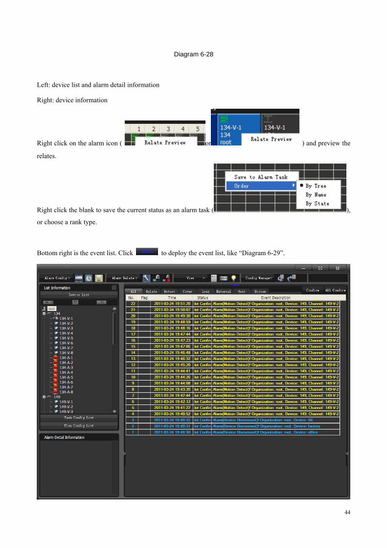
Left: device list and alarm detail information
Right: device information
Right click on the alarm icon ( or ) and preview the
relates.
Right click the blank to save the current status as an alarm task ( ),
or choose a rank type.
Bottom right is the event list. Click to deploy the event list, like “Diagram 6-29”.

45
Diagram 6-29
Alarm configuration steps:
1. Task
There are FOUR methods to set task. The task icon will be in green as you set the task.
� manually right click on the camera/device/node to enable or stop the tasks.
� Select the alarm type in device list, e.g. set the task for all the devices and alarm type of “134” group.
� right click on the alarm icons -- , , , to enable or stop the tasks.
� set a task first and tick the items. This is the most convenient way to set the task.
Plan the time periods for different tasks. Please refer 6.3.1 TASK CONFIG, 6.3.2 PLAN CONFIG
Introduction: stop task is the same method as enable it.
2. Global config , please refer chapter 6.3.4 GLOBAL CONFIG
3. Relate config, please refer chapter 6.3.3 RELATE CONFIG
After you set the task, global config and relate config, the alarm icons on screens will be in red as alarm occur. The
alarm relates are:
Sound: enable the function and select a audio file(format: .wav)
TV wall: enable the function, the alarm video will be send to TV wall as the alarm occur.
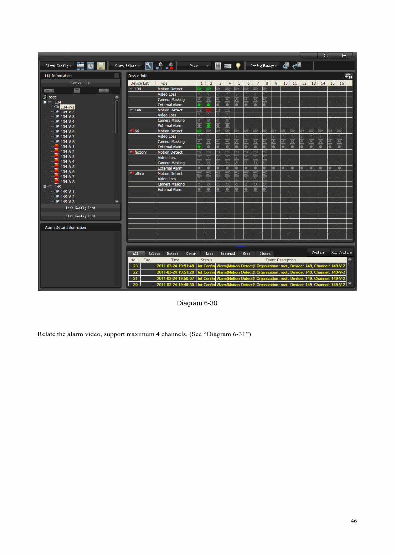
Alarm interface: enable the function, the alarm interface will pop up as the alarm occur. (See “Diagram 6-30”)
46
Diagram 6-30
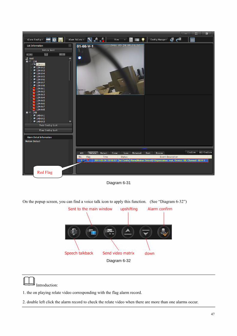
Relate the alarm video, support maximum 4 channels. (See “Diagram 6-31”)
47
Diagram 6-31
On the popup screen, you can find a voice talk icon to apply this function. (See “Diagram 6-32”)
Diagram 6-32
Introduction:
1. the on playing relate video corresponding with the flag alarm record.
2. double left click the alarm record to check the relate video when there are more than one alarms occur.
Red Flag
48
3. turn to the next or previous video by down and up icon.
4. click “Confirm” to end the video relate.
5. double left click to full screen this window.
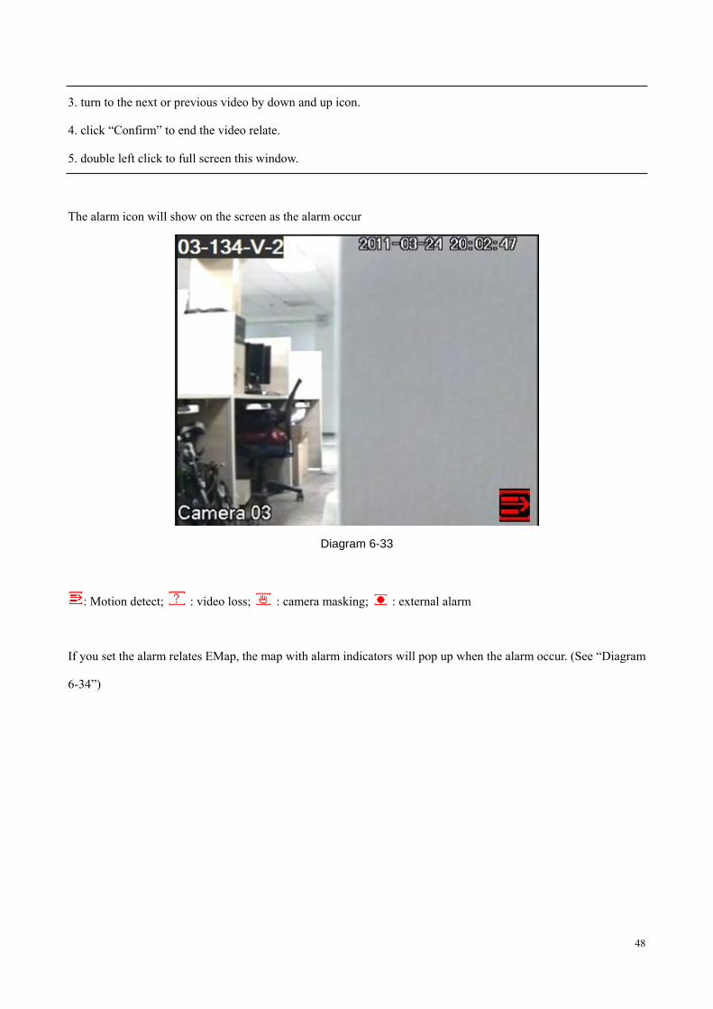
The alarm icon will show on the screen as the alarm occur
Diagram 6-33
: Motion detect; : video loss; : camera masking; : external alarm
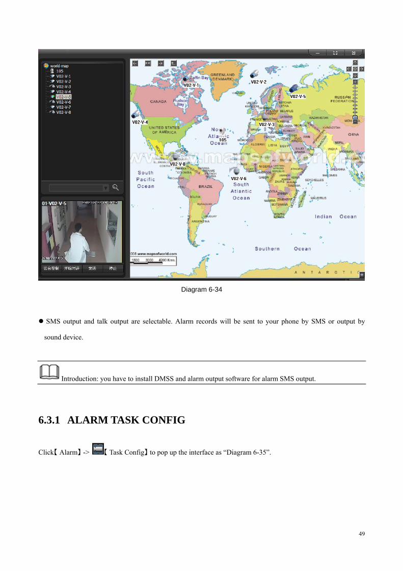
If you set the alarm relates EMap, the map with alarm indicators will pop up when the alarm occur. (See “Diagram
6-34”)
49
Diagram 6-34
SMS output and talk output are selectable. Alarm records will be sent to your phone by SMS or output by
sound device.
Introduction: you have to install DMSS and alarm output software for alarm SMS output.
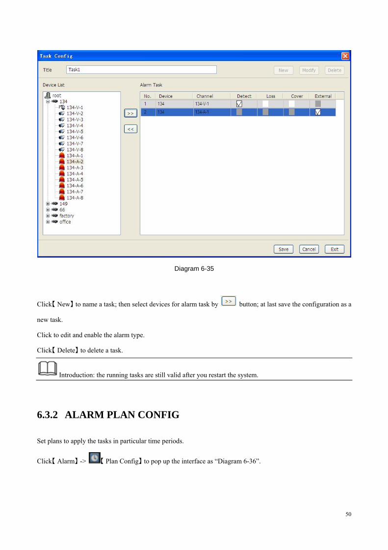
6.3.1 ALARM TASK CONFIG
Click【 】Alarm -> 【 】Task Config to pop up the interface as “Diagram 6-35”.
50
Diagram 6-35
Click【 】New to name a task; then select devices for alarm task by button; at last save the configuration as a
new task.
Click to edit and enable the alarm type.
Click【 】Delete to delete a task.
Introduction: the running tasks are still valid after you restart the system.
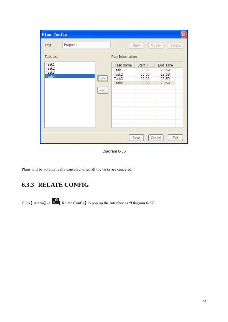
6.3.2 ALARM PLAN CONFIG
Set plans to apply the tasks in particular time periods.
Click【 】Alarm -> 【 】Plan Config to pop up the interface as “Diagram 6-36”.
51
Diagram 6-36
Plans will be automatically canceled when all the tasks are canceled.
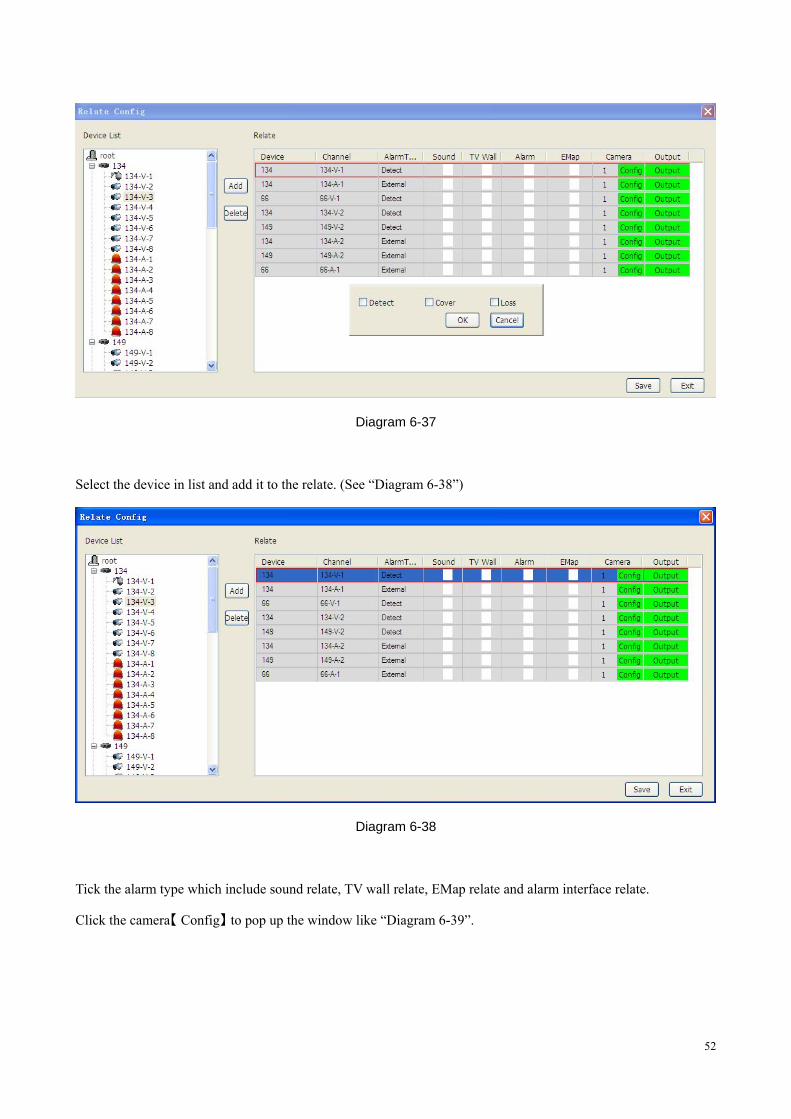
6.3.3 RELATE CONFIG
Click【 】Alarm -> 【 】Relate Config to pop up the interface as “Diagram 6-37”.
52
Diagram 6-37
Select the device in list and add it to the relate. (See “Diagram 6-38”)
Diagram 6-38
Tick the alarm type which include sound relate, TV wall relate, EMap relate and alarm interface relate.
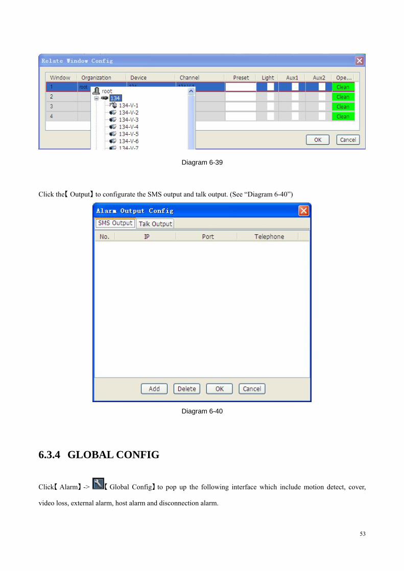
Click the camera【 】Config to pop up the window like “Diagram 6-39”.
53
Diagram 6-39
Click the【 】Output to configurate the SMS output and talk output. (See “Diagram 6-40”)
Diagram 6-40
6.3.4 GLOBAL CONFIG
Click【 】Alarm -> 【 】Global Config to pop up the following interface which include motion detect, cover,
video loss, external alarm, host alarm and disconnection alarm.
54
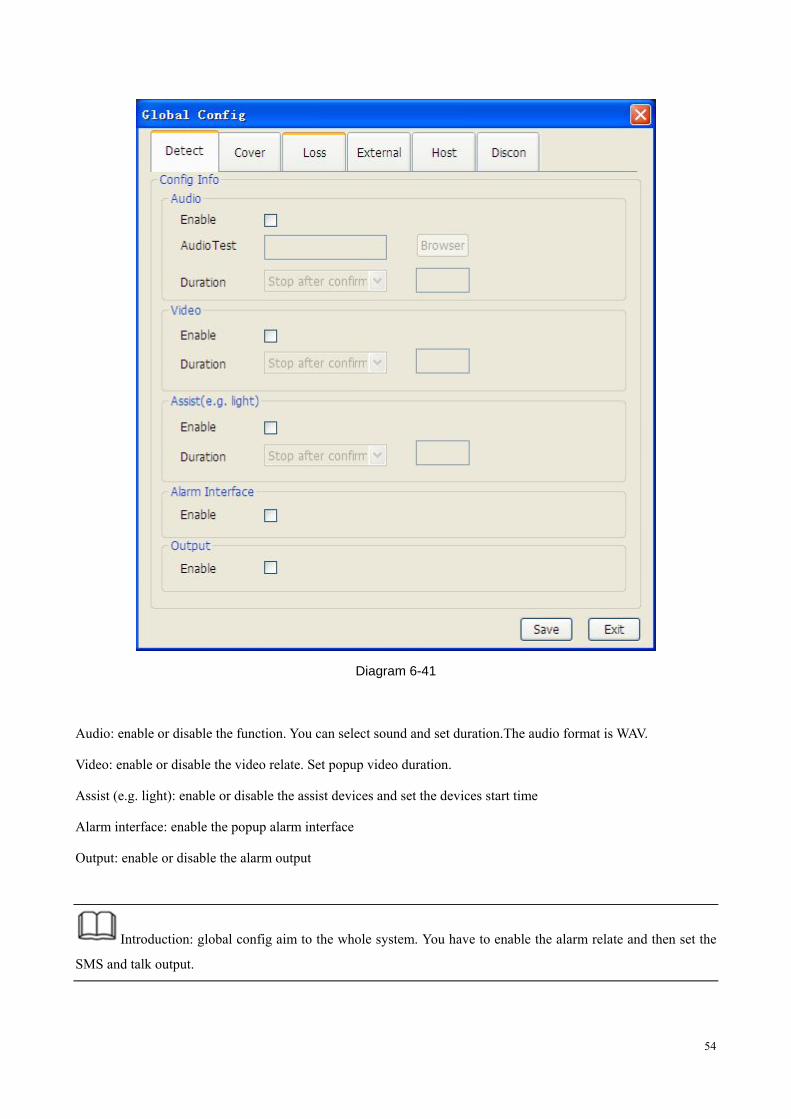
Diagram 6-41
Audio: enable or disable the function. You can select sound and set duration.The audio format is WAV.
Video: enable or disable the video relate. Set popup video duration.
Assist (e.g. light): enable or disable the assist devices and set the devices start time
Alarm interface: enable the popup alarm interface
Output: enable or disable the alarm output
Introduction: global config aim to the whole system. You have to enable the alarm relate and then set the
SMS and talk output.
55
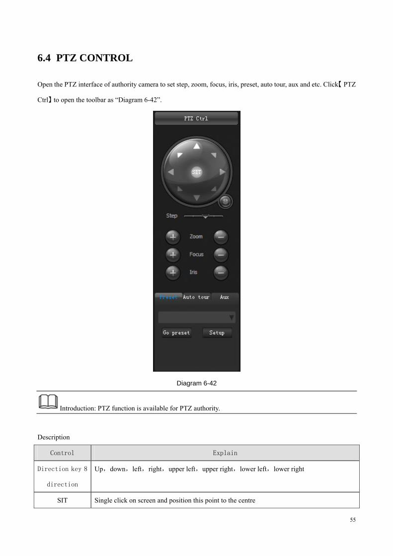
6.4 PTZ CONTROL
Open the PTZ interface of authority camera to set step, zoom, focus, iris, preset, auto tour, aux and etc. Click【 PTZ
Ctrl】 to open the toolbar as “Diagram 6-42”.
Diagram 6-42
Introduction: PTZ function is available for PTZ authority.
Description
Control Explain
Direction key 8
direction
Up,down,left,right,upper left,upper right,lower left,lower right
SIT Single click on screen and position this point to the centre
56
Support 1-36 zoom in/out function enlarge the selected screen by dragging bottom-up,vice
versa.(only controlled by mouse)
Simulate
joystick
Enable the function,control the step and camera movement by simulate joystick.Scroll wheel
control the camera zoom.
Step There are 1-8 degrees
Zoom Control the camera zoom
Focus Modify the definition
Iris Modify brightness
Preset When Pan/Tilt moves to the target position, input the preset number and save it.
Auto tour Auto tour lines
Aux Light on,light off
Form 6-2
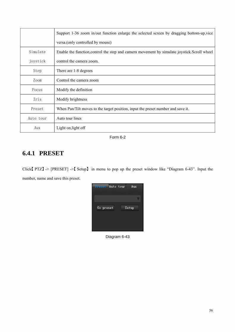
6.4.1 PRESET
Click【 】PTZ -> [PRESET] ->【 】Setup in menu to pop up the preset window like “Diagram 6-43”. Input the
number, name and save this preset.
Diagram 6-43
57
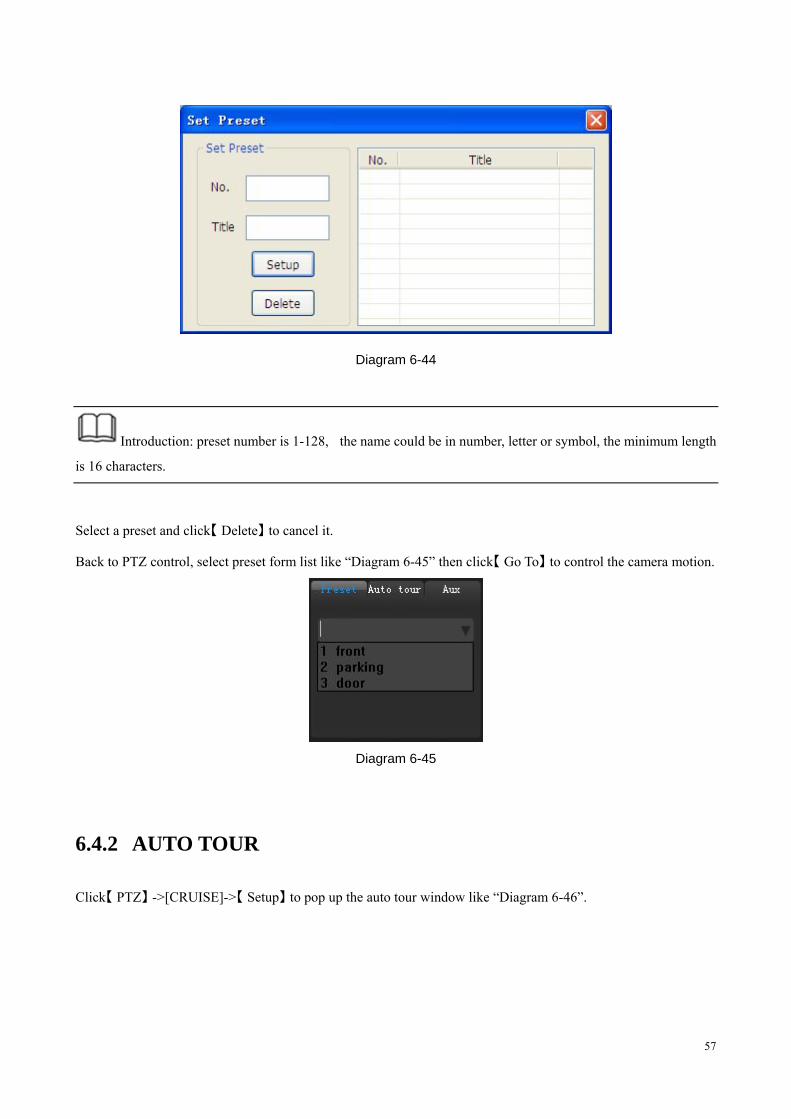
Diagram 6-44
Introduction: preset number is 1-128, the name could be in number, letter or symbol, the minimum length
is 16 characters.
Select a preset and click【 】Delete to cancel it.
Back to PTZ control, select preset form list like “Diagram 6-45” then click【 】Go To to control the camera motion.
Diagram 6-45
6.4.2 AUTO TOUR
Click【 】PTZ ->[CRUISE]->【 】Setup to pop up the auto tour window like “Diagram 6-46”.
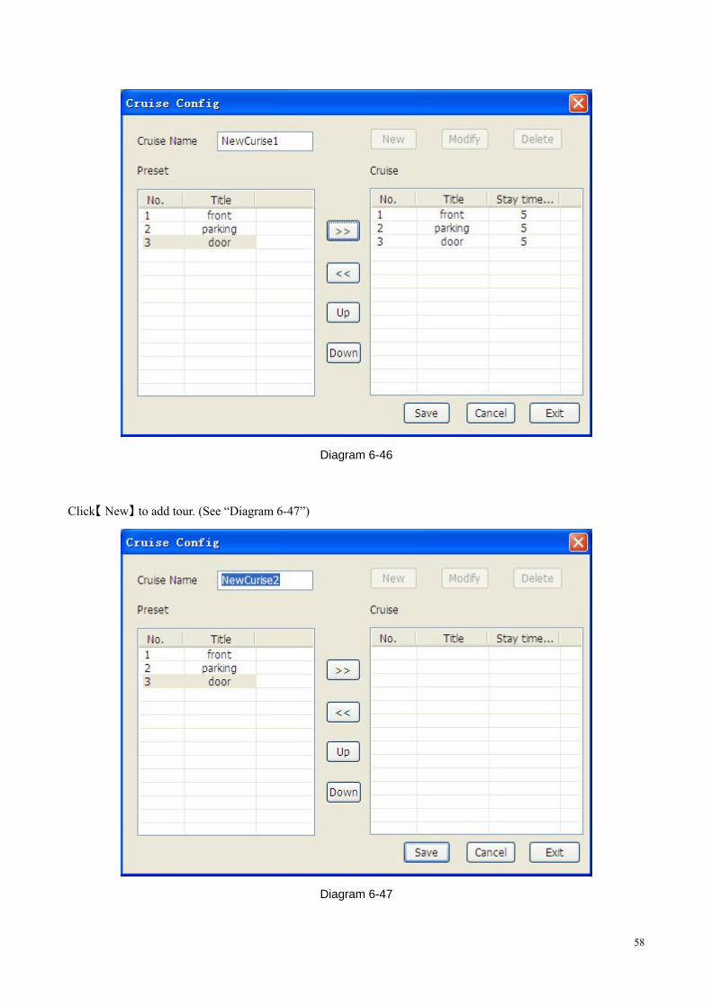
58
Diagram 6-46
Click【 】New to add tour. (See “Diagram 6-47”)
Diagram 6-47
59
� tour name, can be modified.
� select preset in list and add it into tour by . The maximum presets are 100 in one tour.
� double left click stay time to modify, the limit is 3-6000 seconds. The default is 5 seconds.
� select a preset in tour and click to cancel it from this tour.
⑤【 】 【 】Up and Down is used for change the presets sequence and the tour line.
⑥ 【 】 click Save to complete the setting
The operation of【 】Modify is the same as add a new tour
【 】Delete is used for delete a tour
Click【 】Exit to quit
Introduction: you can add several presets into tour at once.
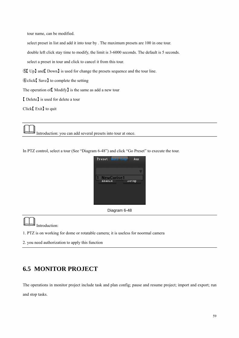
In PTZ control, select a tour (See “Diagram 6-48”) and click “Go Preset” to execute the tour.
Diagram 6-48
Introduction:
1. PTZ is on working for dome or rotatable camera; it is useless for noormal camera
2. you need authorization to apply this function
6.5 MONITOR PROJECT
The operations in monitor project include task and plan config; pause and resume project; import and export; run
and stop tasks.
60
6.5.1 TASK CONFIG
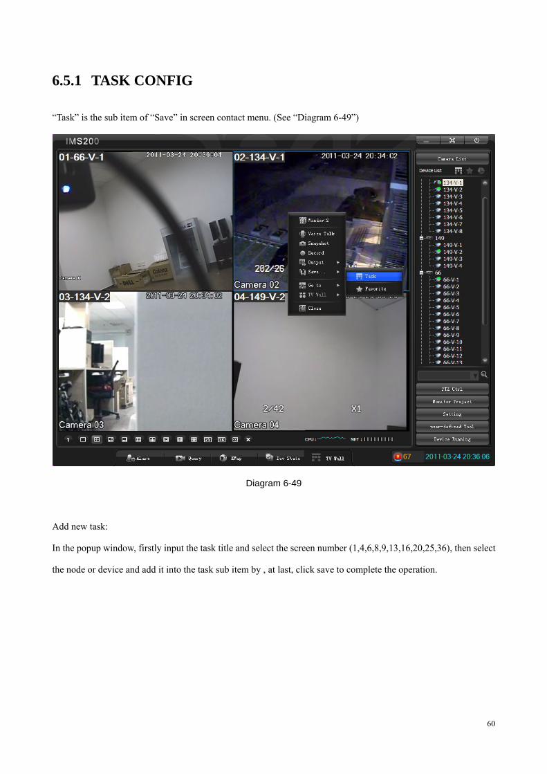
“Task” is the sub item of “Save” in screen contact menu. (See “Diagram 6-49”)
Diagram 6-49
Add new task:
In the popup window, firstly input the task title and select the screen number (1,4,6,8,9,13,16,20,25,36), then select
the node or device and add it into the task sub item by , at last, click save to complete the operation.
61
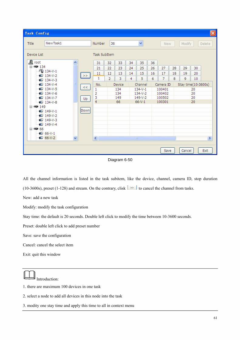
Diagram 6-50
All the channel information is listed in the task subitem, like the device, channel, camera ID, stop duration
(10-3600s), preset (1-128) and stream. On the contrary, clisk to cancel the channel from tasks.
New: add a new task
Modify: modify the task configuration
Stay time: the default is 20 seconds. Double left click to modify the time between 10-3600 seconds.
Preset: double left click to add preset number
Save: save the configuration
Cancel: cancel the select item
Exit: quit this window
Introduction:
1. there are maximum 100 devices in one task
2. select a node to add all devices in this node into the task
3. modity one stay time and apply this time to all in context menu
62
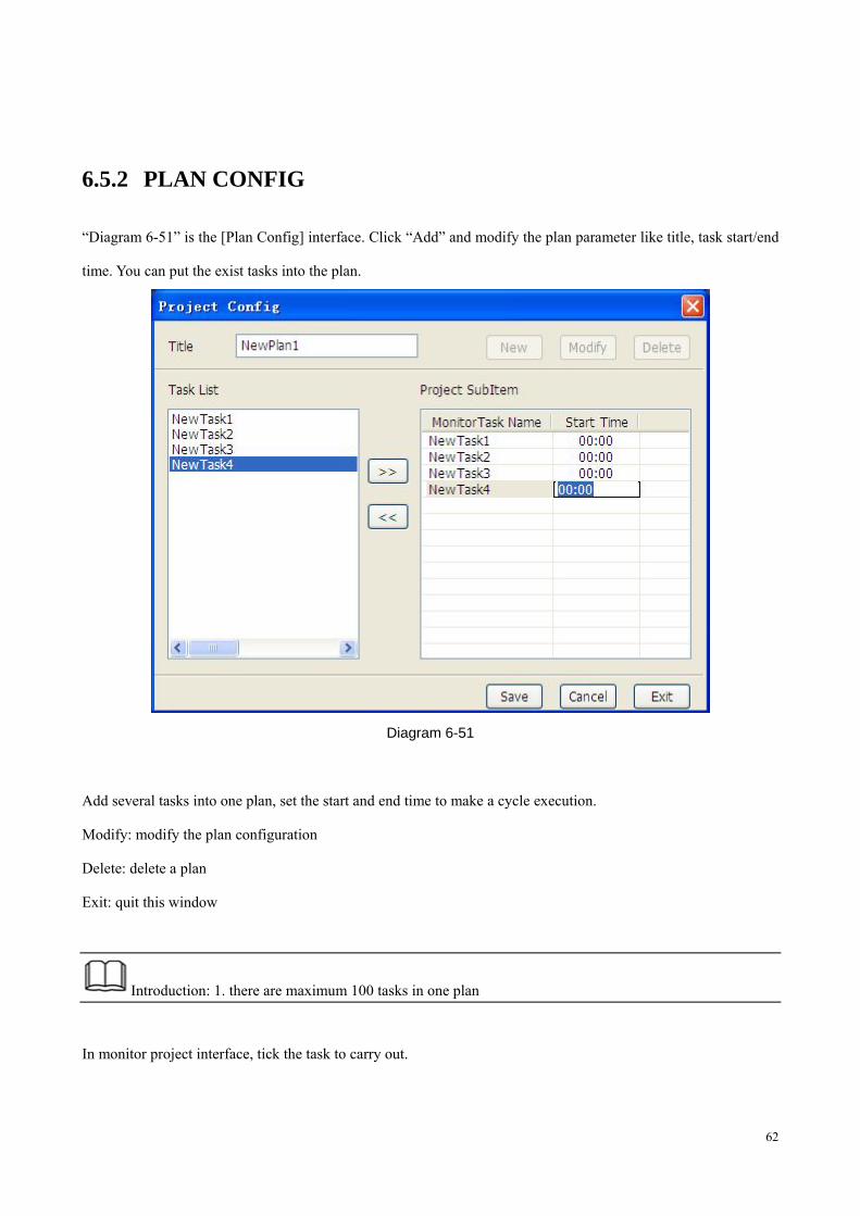
6.5.2 PLAN CONFIG
“Diagram 6-51” is the [Plan Config] interface. Click “Add” and modify the plan parameter like title, task start/end
time. You can put the exist tasks into the plan.
Diagram 6-51
Add several tasks into one plan, set the start and end time to make a cycle execution.
Modify: modify the plan configuration
Delete: delete a plan
Exit: quit this window
Introduction: 1. there are maximum 100 tasks in one plan
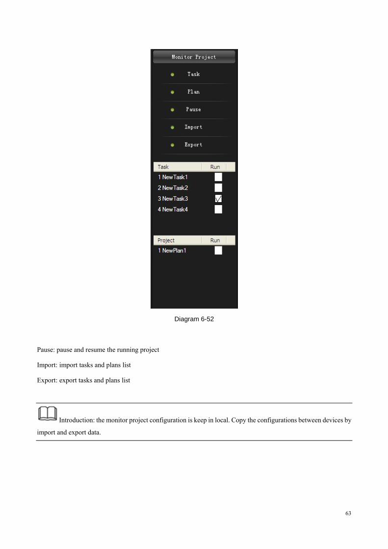
In monitor project interface, tick the task to carry out.
63
Diagram 6-52
Pause: pause and resume the running project
Import: import tasks and plans list
Export: export tasks and plans list
Introduction: the monitor project configuration is keep in local. Copy the configurations between devices by
import and export data.
64
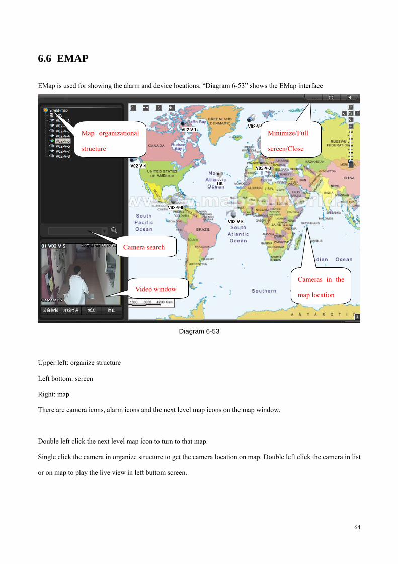
6.6 EMAP
EMap is used for showing the alarm and device locations. “Diagram 6-53” shows the EMap interface
Diagram 6-53
Upper left: organize structure
Left bottom: screen
Right: map
There are camera icons, alarm icons and the next level map icons on the map window.
Double left click the next level map icon to turn to that map.
Single click the camera in organize structure to get the camera location on map. Double left click the camera in list
or on map to play the live view in left buttom screen.
Minimize/Full
screen/Close
Cameras in the
map location
Map organizational
structure
Camera search
Video window
65
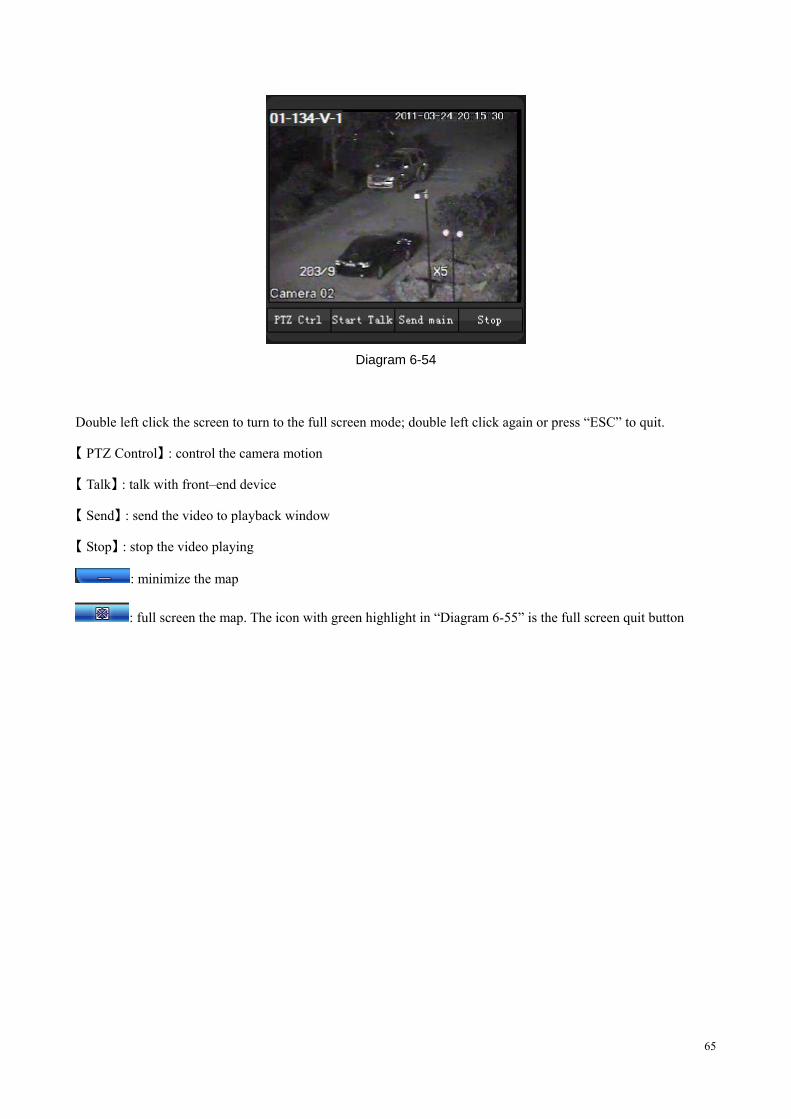
Diagram 6-54
Double left click the screen to turn to the full screen mode; double left click again or press “ESC” to quit.
【 】PTZ Control : control the camera motion
【 】Talk : talk with front–end device
【 】Send : send the video to playback window
【 】Stop : stop the video playing
: minimize the map
: full screen the map. The icon with green highlight in “Diagram 6-55” is the full screen quit button
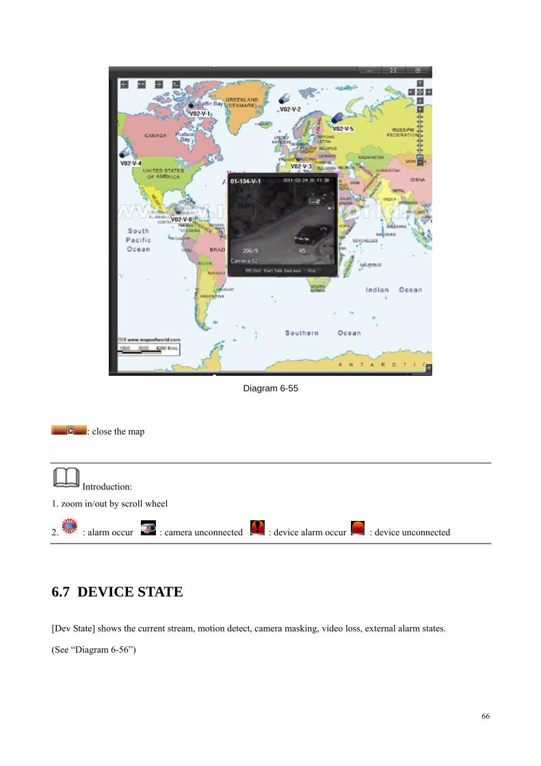
66
Diagram 6-55
: close the map
Introduction:
1. zoom in/out by scroll wheel
2. : alarm occur : camera unconnected : device alarm occur : device unconnected
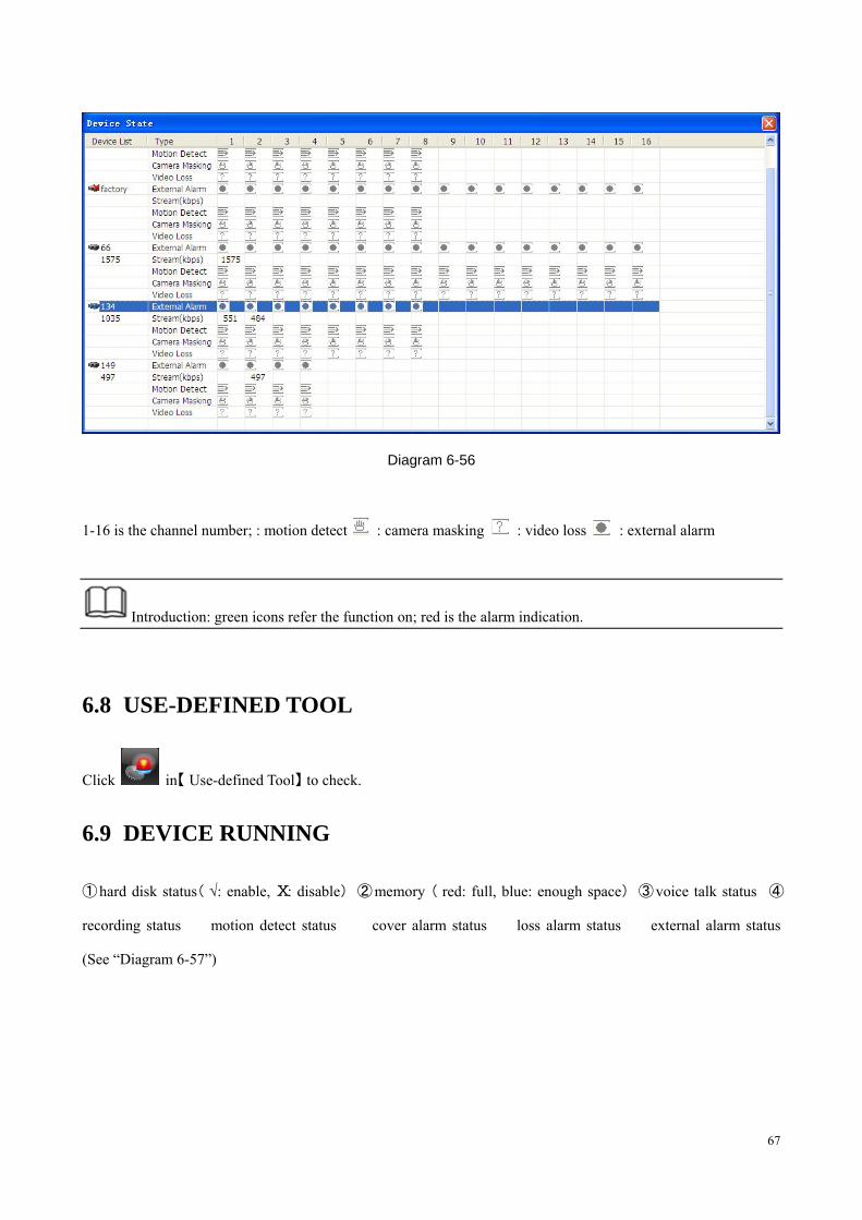
6.7 DEVICE STATE
[Dev State] shows the current stream, motion detect, camera masking, video loss, external alarm states.
(See “Diagram 6-56”)
67
Diagram 6-56
1-16 is the channel number; : motion detect : camera masking : video loss : external alarm
Introduction: green icons refer the function on; red is the alarm indication.
6.8 USE-DEFINED TOOL
Click in【 Use-defined Tool】 to check.
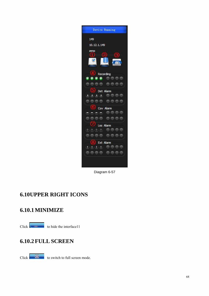
6.9 DEVICE RUNNING
① ( hard disk status √: enable, Ⅹ ) ② ( ) ③ ④: disable memory red: full, blue: enough space voice talk status
recording status � motion detect status � cover alarm status � loss alarm status � external alarm status
(See “Diagram 6-57”)
68
Diagram 6-57
6.10 UPPER RIGHT ICONS
6.10.1 MINIMIZE
Click to hide the interface11
6.10.2 FULL SCREEN
Click to switch to full screen mode.
69
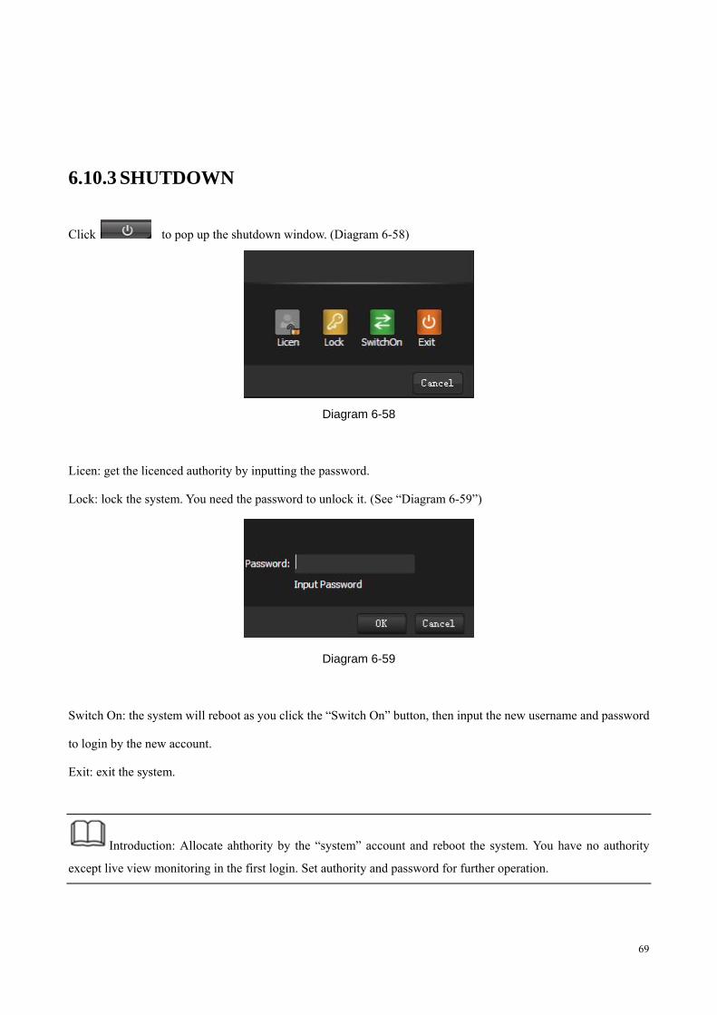
6.10.3 SHUTDOWN
Click to pop up the shutdown window. (Diagram 6-58)
Diagram 6-58
Licen: get the licenced authority by inputting the password.
Lock: lock the system. You need the password to unlock it. (See “Diagram 6-59”)
Diagram 6-59
Switch On: the system will reboot as you click the “Switch On” button, then input the new username and password
to login by the new account.
Exit: exit the system.
Introduction: Allocate ahthority by the “system” account and reboot the system. You have no authority
except live view monitoring in the first login. Set authority and password for further operation.
70
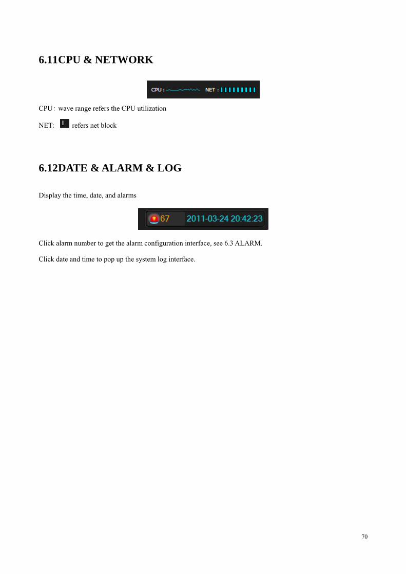
6.11 CPU & NETWORK
CPU: wave range refers the CPU utilization
NET: refers net block
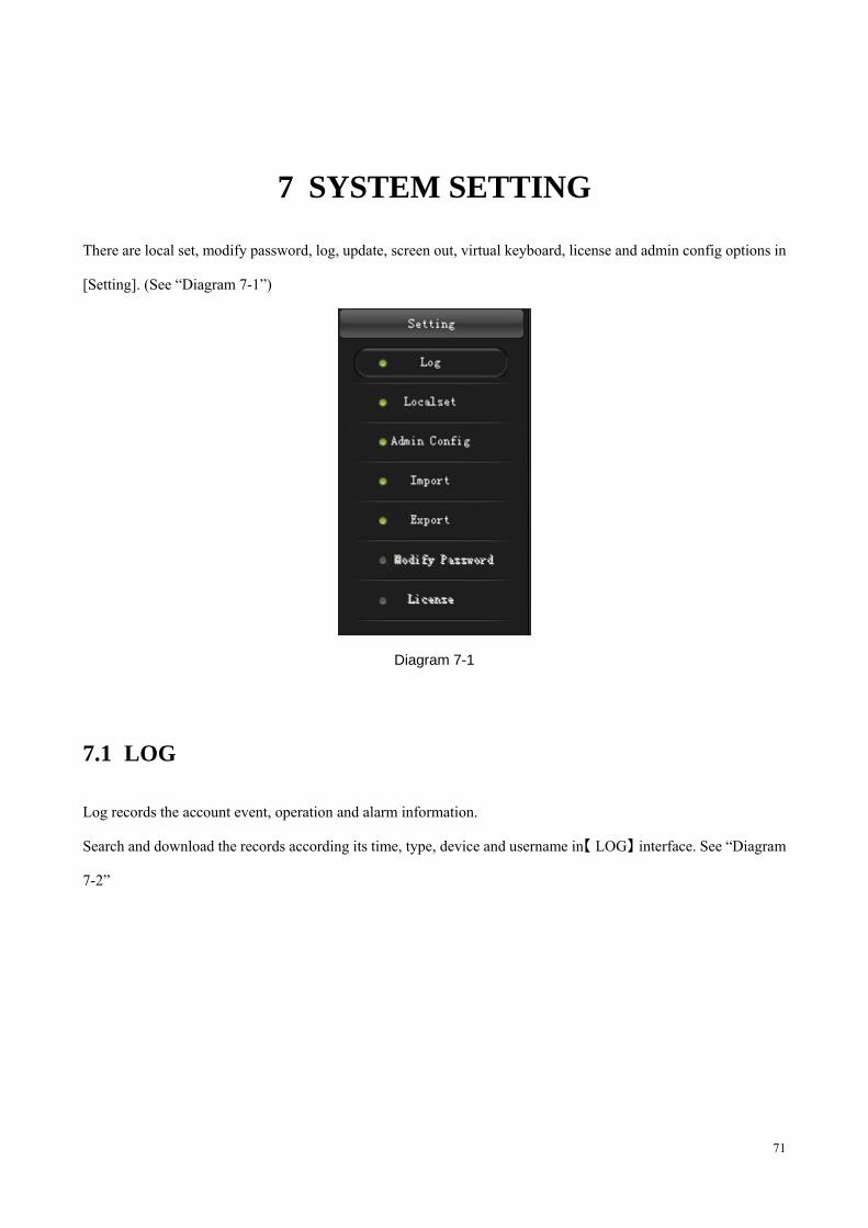
6.12 DATE & ALARM & LOG
Display the time, date, and alarms
Click alarm number to get the alarm configuration interface, see 6.3 ALARM.
Click date and time to pop up the system log interface.
71
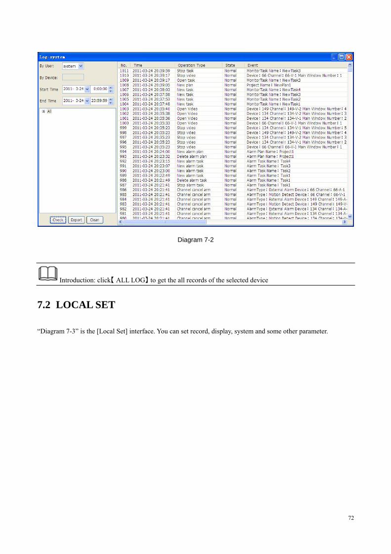
7 SYSTEM SETTING
There are local set, modify password, log, update, screen out, virtual keyboard, license and admin config options in
[Setting]. (See “Diagram 7-1”)
Diagram 7-1
7.1 LOG
Log records the account event, operation and alarm information.
Search and download the records according its time, type, device and username in【 】LOG interface. See “Diagram
7-2”
72
Diagram 7-2
Introduction: click【 】ALL LOG to get the all records of the selected device
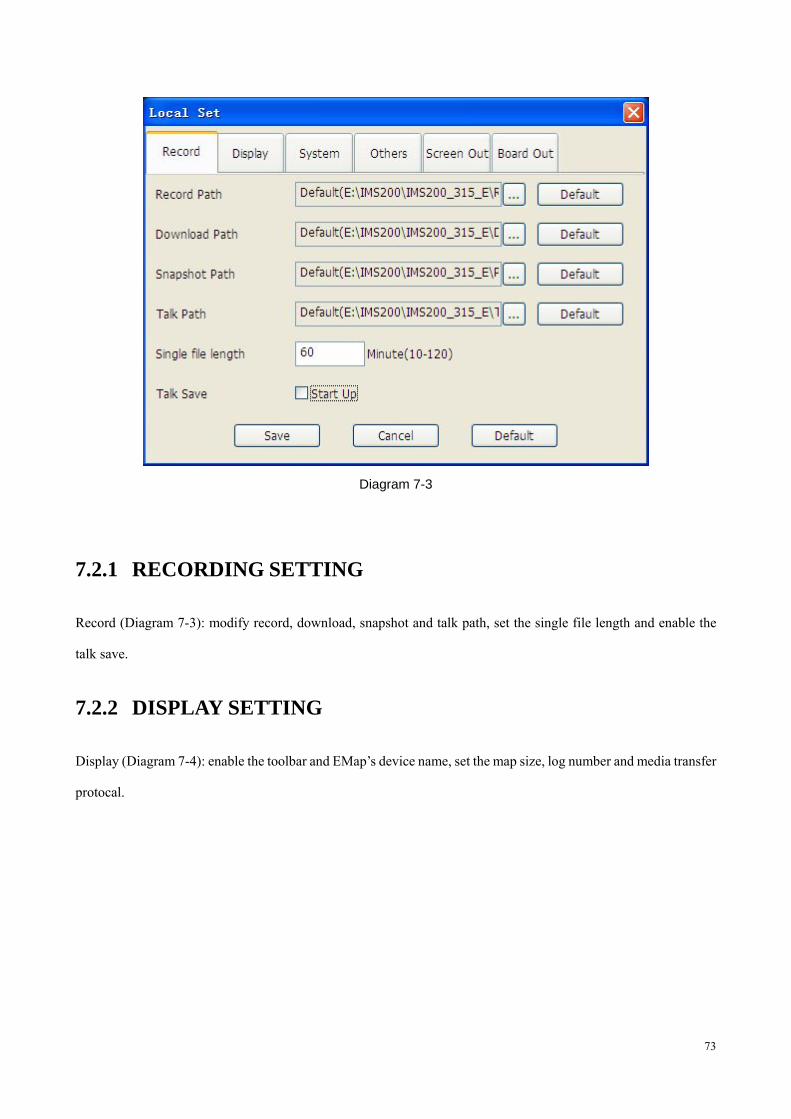
7.2 LOCAL SET
“Diagram 7-3” is the [Local Set] interface. You can set record, display, system and some other parameter.
73
Diagram 7-3
7.2.1 RECORDING SETTING
Record (Diagram 7-3): modify record, download, snapshot and talk path, set the single file length and enable the
talk save.
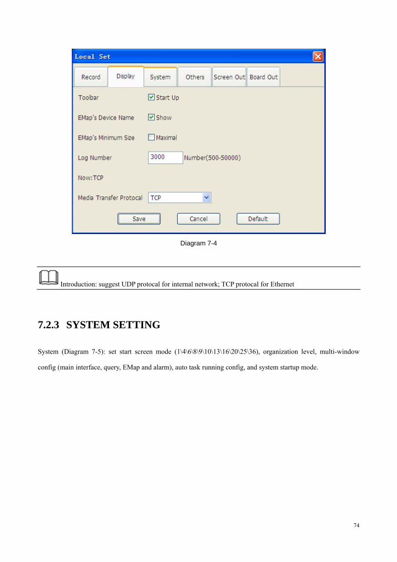
7.2.2 DISPLAY SETTING
Display (Diagram 7-4): enable the toolbar and EMap’s device name, set the map size, log number and media transfer
protocal.
74
Diagram 7-4
Introduction: suggest UDP protocal for internal network; TCP protocal for Ethernet
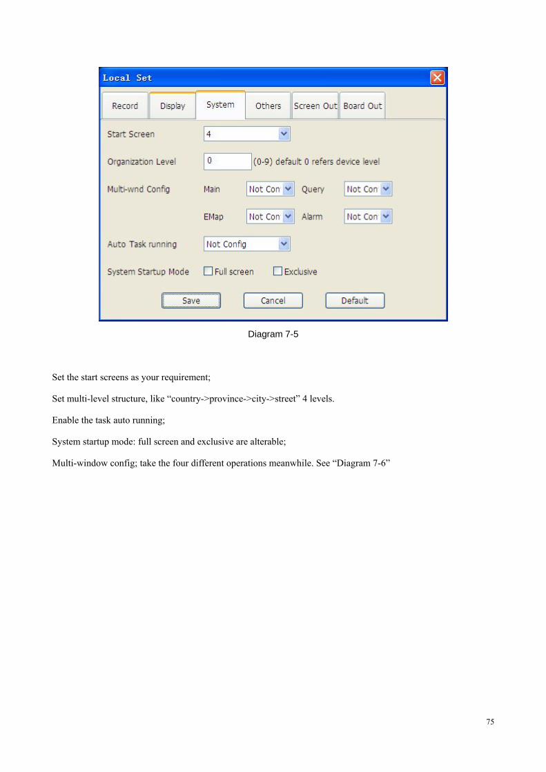
7.2.3 SYSTEM SETTING
System (Diagram 7-5): set start screen mode (1\4\6\8\9\10\13\16\20\25\36), organization level, multi-window
config (main interface, query, EMap and alarm), auto task running config, and system startup mode.
75
Diagram 7-5
Set the start screens as your requirement;
Set multi-level structure, like “country->province->city->street” 4 levels.
Enable the task auto running;
System startup mode: full screen and exclusive are alterable;
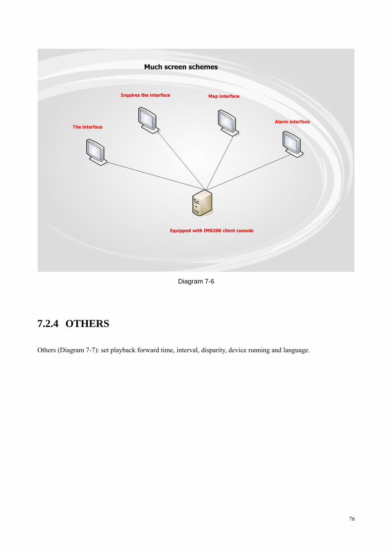
Multi-window config; take the four different operations meanwhile. See “Diagram 7-6”
76
Diagram 7-6
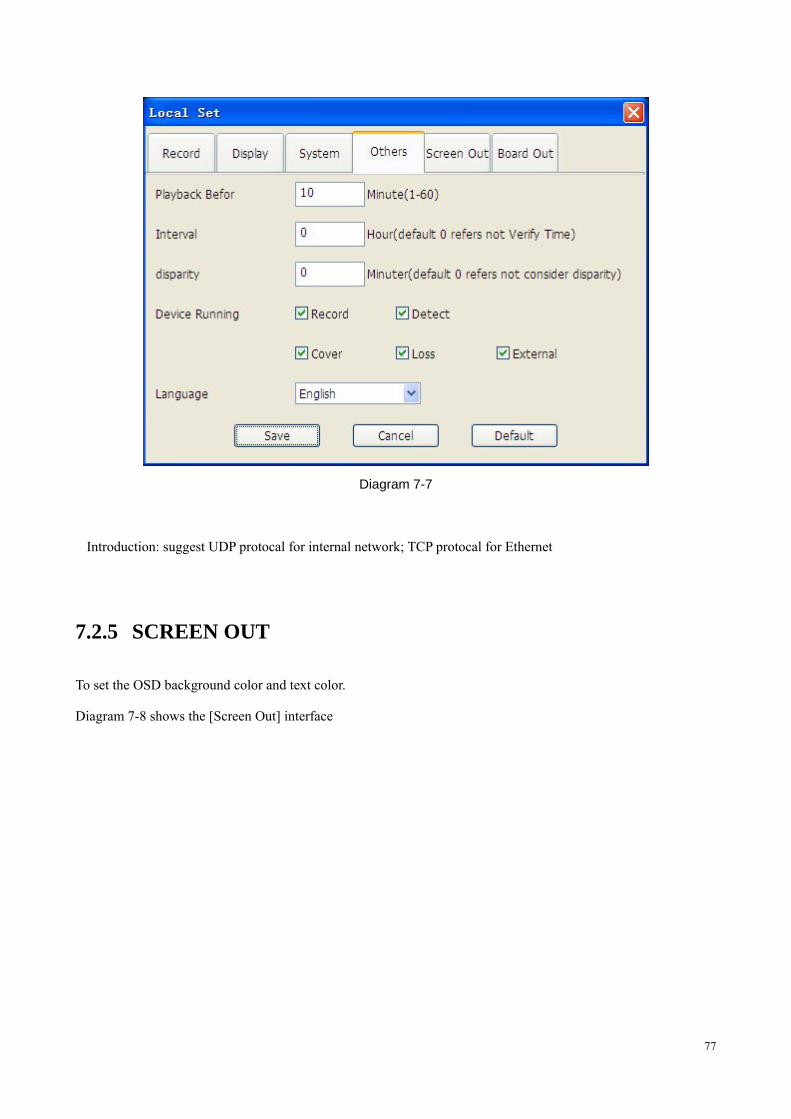
7.2.4 OTHERS
Others (Diagram 7-7): set playback forward time, interval, disparity, device running and language.
77
Diagram 7-7
Introduction: suggest UDP protocal for internal network; TCP protocal for Ethernet
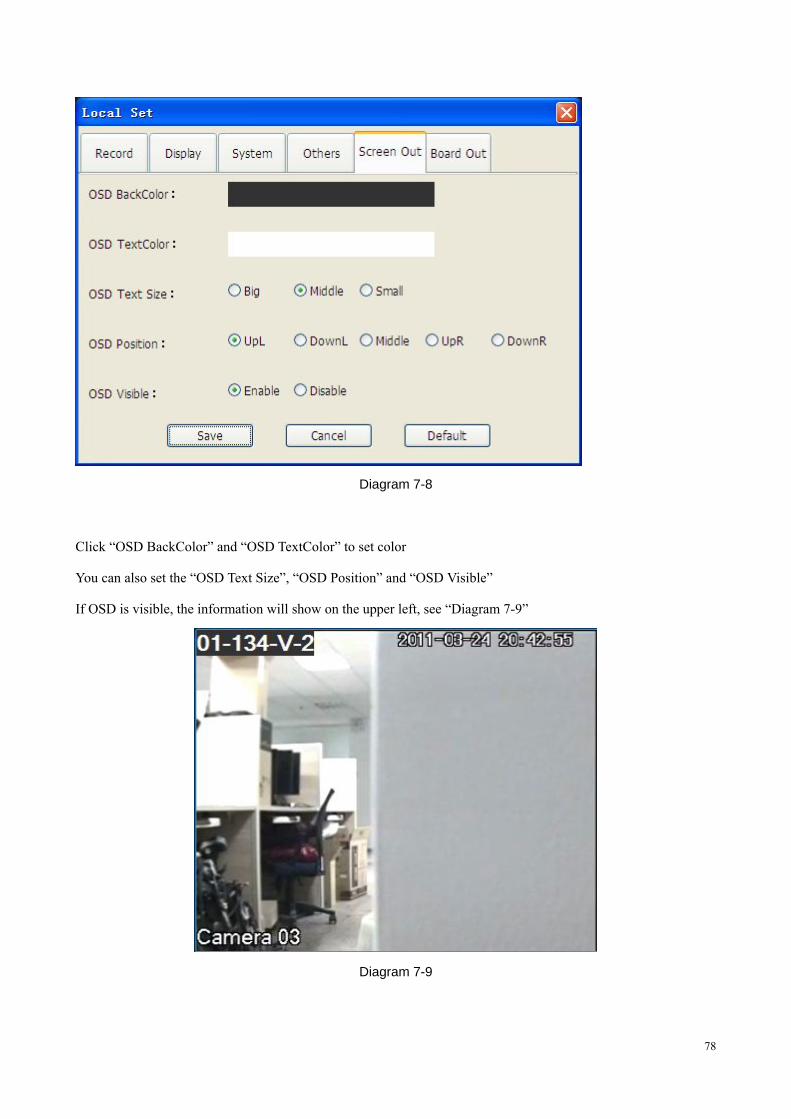
7.2.5 SCREEN OUT
To set the OSD background color and text color.
Diagram 7-8 shows the [Screen Out] interface
78
Diagram 7-8
Click “OSD BackColor” and “OSD TextColor” to set color
You can also set the “OSD Text Size”, “OSD Position” and “OSD Visible”
If OSD is visible, the information will show on the upper left, see “Diagram 7-9”
Diagram 7-9
79
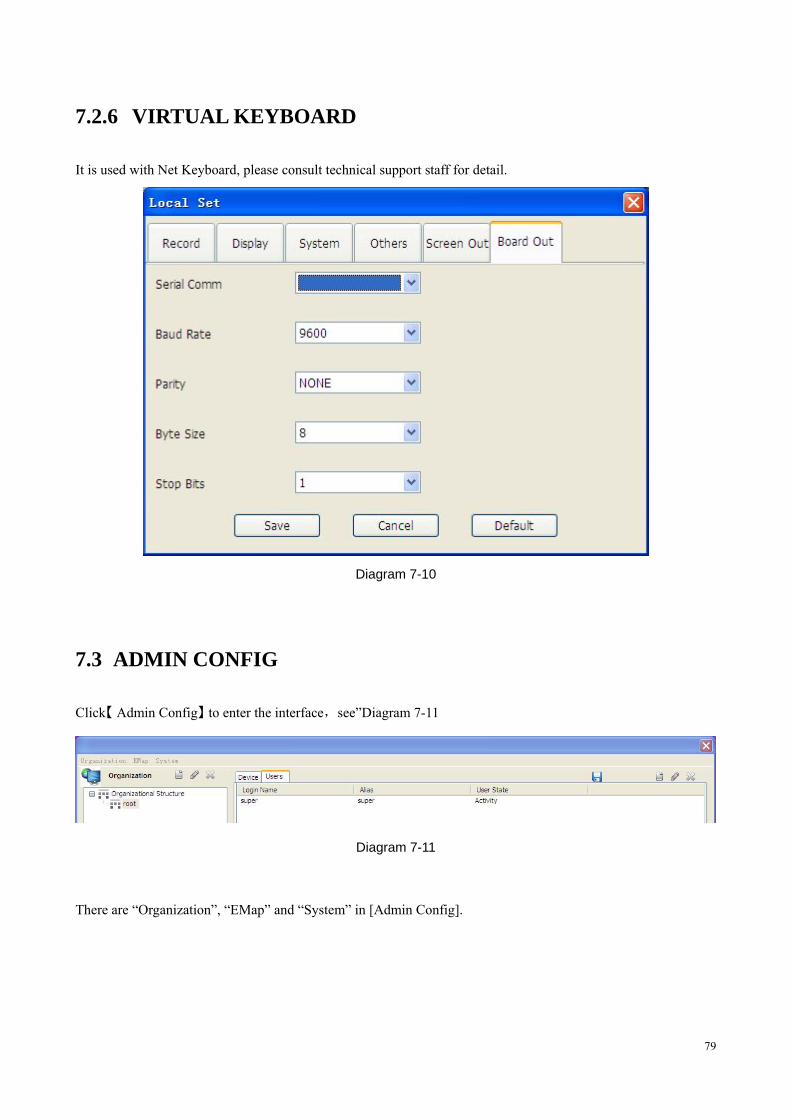
7.2.6 VIRTUAL KEYBOARD
It is used with Net Keyboard, please consult technical support staff for detail.
Diagram 7-10
7.3 ADMIN CONFIG
Click【 】Admin Config to enter the interface,see”Diagram 7-11
Diagram 7-11
There are “Organization”, “EMap” and “System” in [Admin Config].
80
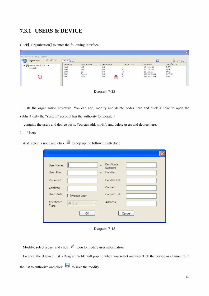
7.3.1 USERS & DEVICE
Click【 】Organization to enter the following interface
Diagram 7-12
� lists the organization structure. You can add, modify and delete nodes here and click a noke to open the
sublist( only the “system” account has the authority to operate.)
� contains the users and device parts. You can add, modify and delete users and device here.
1. Users
�Add: select a node and click to pop up the following interface
Diagram 7-13
�Modify: select a user and click icon to modify user information
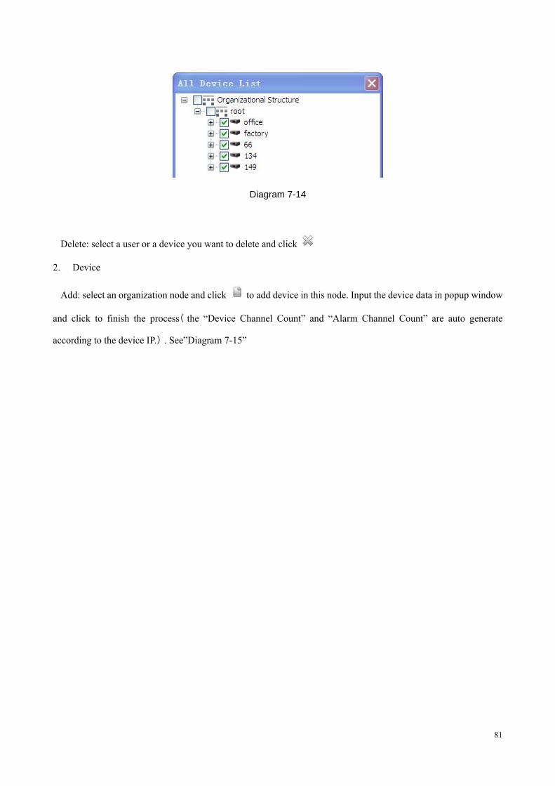
�License: the [Device List] (Diagram 7-14) will pop up when you select one user Tick the device or channel to in
the list to authorize and click to save the modify.
81
Diagram 7-14
�Delete: select a user or a device you want to delete and click
2. Device
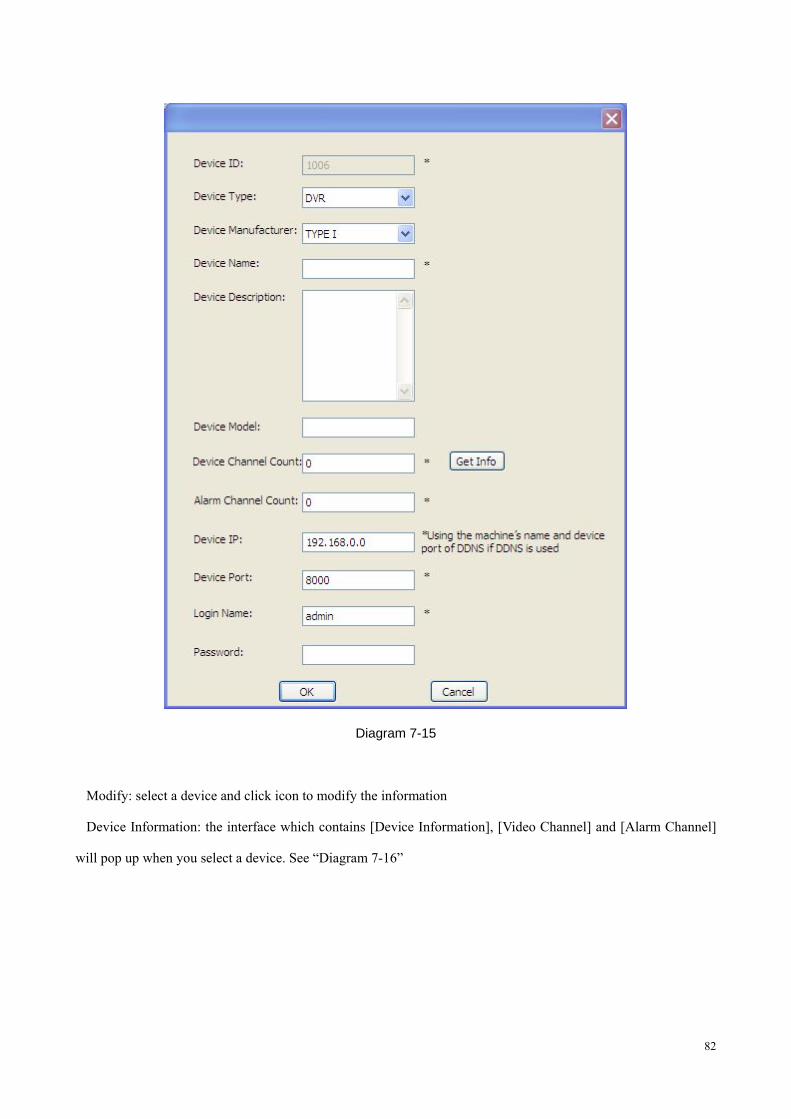
�Add: select an organization node and click to add device in this node. Input the device data in popup window
and click to finish the process( the “Device Channel Count” and “Alarm Channel Count” are auto generate
according to the device IP.) . See”Diagram 7-15”
82
Diagram 7-15
�Modify: select a device and click icon to modify the information
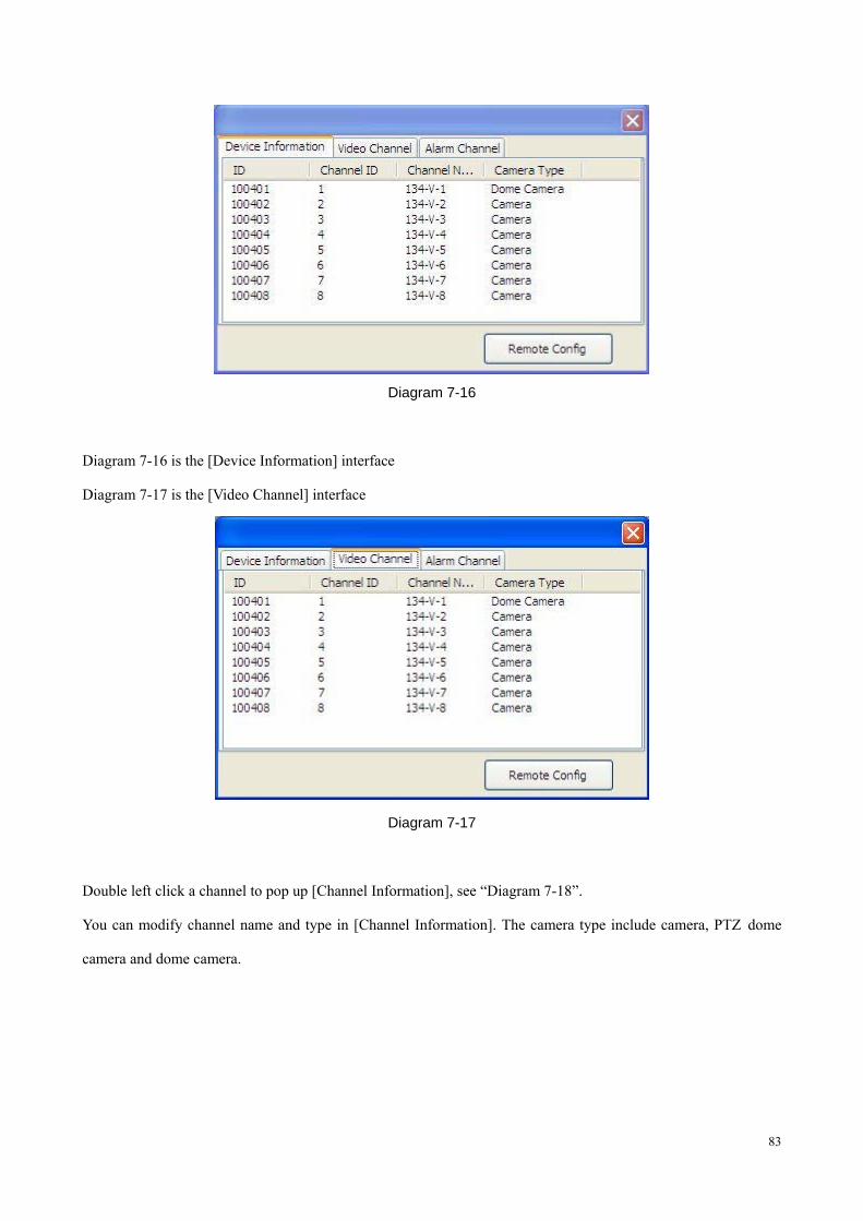
�Device Information: the interface which contains [Device Information], [Video Channel] and [Alarm Channel]
will pop up when you select a device. See “Diagram 7-16”
83
Diagram 7-16
Diagram 7-16 is the [Device Information] interface
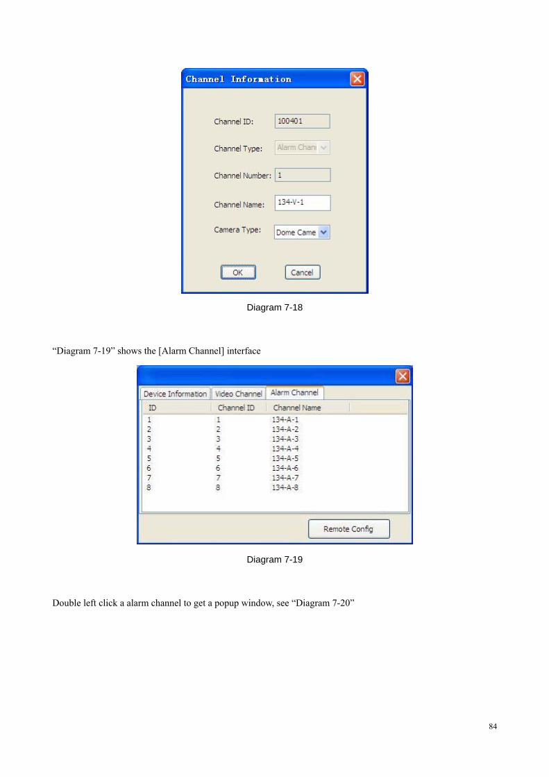
Diagram 7-17 is the [Video Channel] interface
Diagram 7-17
Double left click a channel to pop up [Channel Information], see “Diagram 7-18”.
You can modify channel name and type in [Channel Information]. The camera type include camera, PTZ dome
camera and dome camera.
84
Diagram 7-18
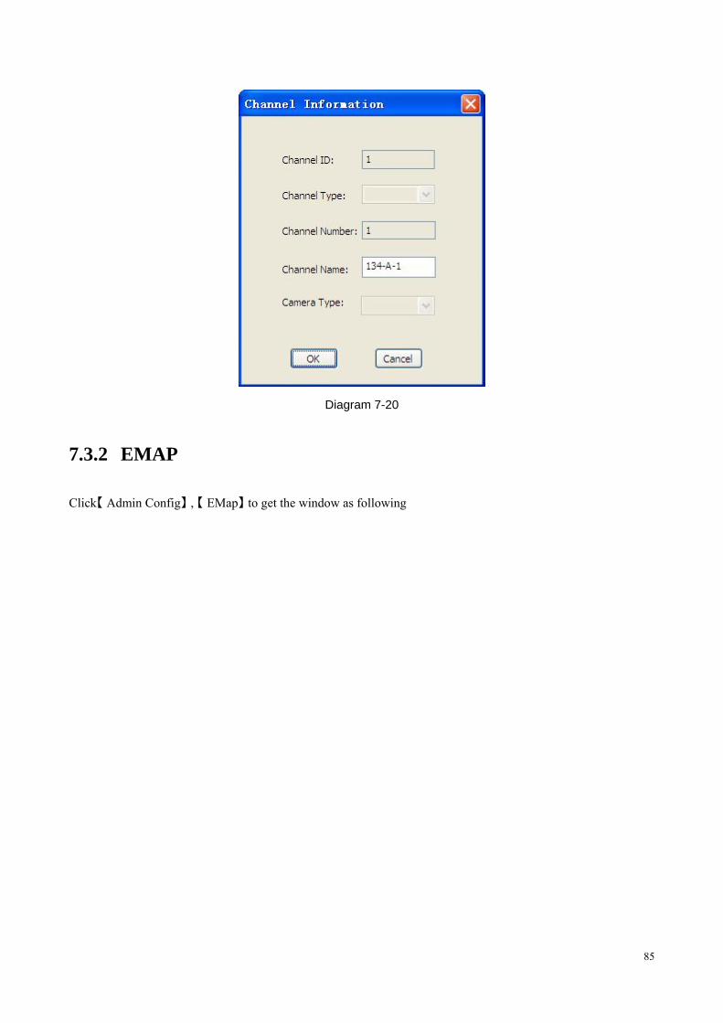
“Diagram 7-19” shows the [Alarm Channel] interface
Diagram 7-19
Double left click a alarm channel to get a popup window, see “Diagram 7-20”
85
Diagram 7-20
7.3.2 EMAP
Click【 】 【Admin Config , EMap】 to get the window as following
86
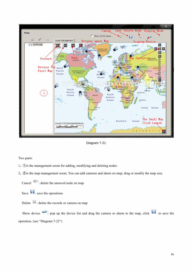
Diagram 7-21
Two parts:
1、① is the management zoom for adding, modifying and deleting nodes
2、② is the map management zoom. You can add cameras and alarm on map; drag or modify the map size.
� Cancel : delete the unsaved node on map
� Save : save the operations
� Delete : delete the records or camera on map
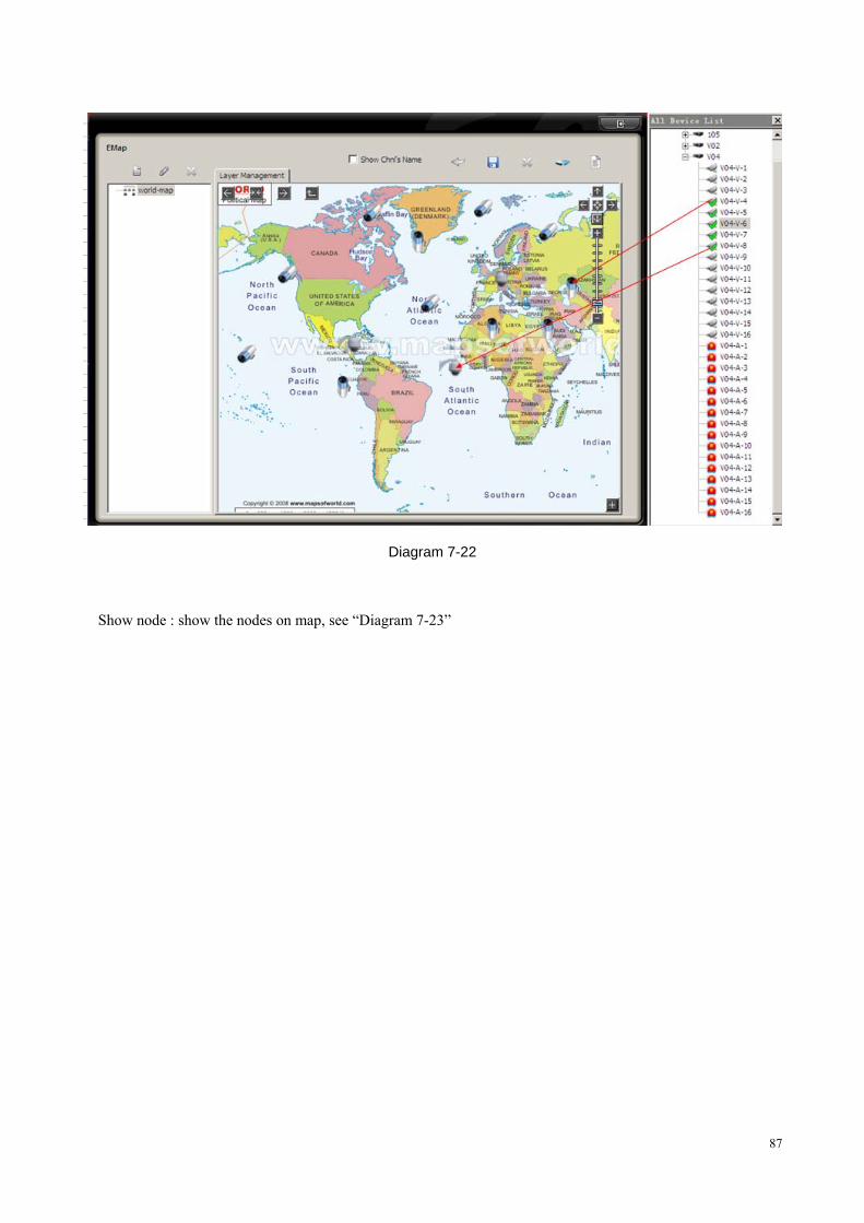
� Show device : pop up the device list and drag the camera or alarm to the map, click to save the
operation. (see “Diagram 7-22”)
87
Diagram 7-22
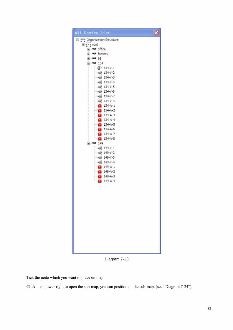
� Show node : show the nodes on map, see “Diagram 7-23”
88
Diagram 7-23
� Tick the node which you want to place on map
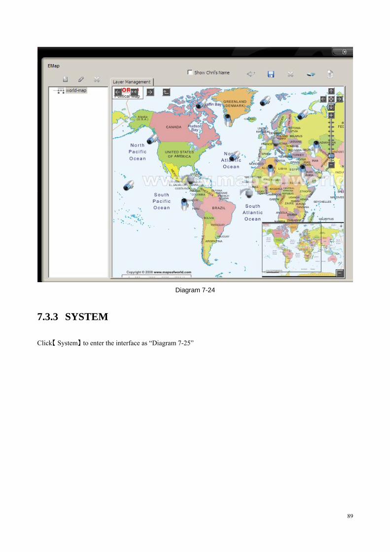
� Click on lower right to open the sub-map, you can position on the sub-map. (see “Diagram 7-24”)
89
Diagram 7-24
7.3.3 SYSTEM
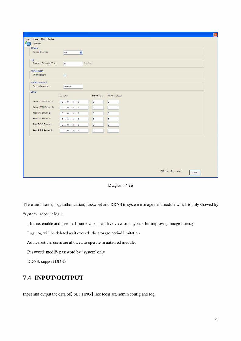
Click【 】System to enter the interface as “Diagram 7-25”
90
Diagram 7-25
There are I frame, log, authorization, password and DDNS in system management module which is only showed by
“system” account login.
� I frame: enable and insert a I frame when start live view or playback for improving image fluency.
� Log: log will be deleted as it exceeds the storage period limitation.
� Authorization: users are allowed to operate in authored module.
� Password: modify password by “system”only
� DDNS: support DDNS
7.4 INPUT/OUTPUT
Input and output the data of【 】SETTING like local set, admin config and log.
91
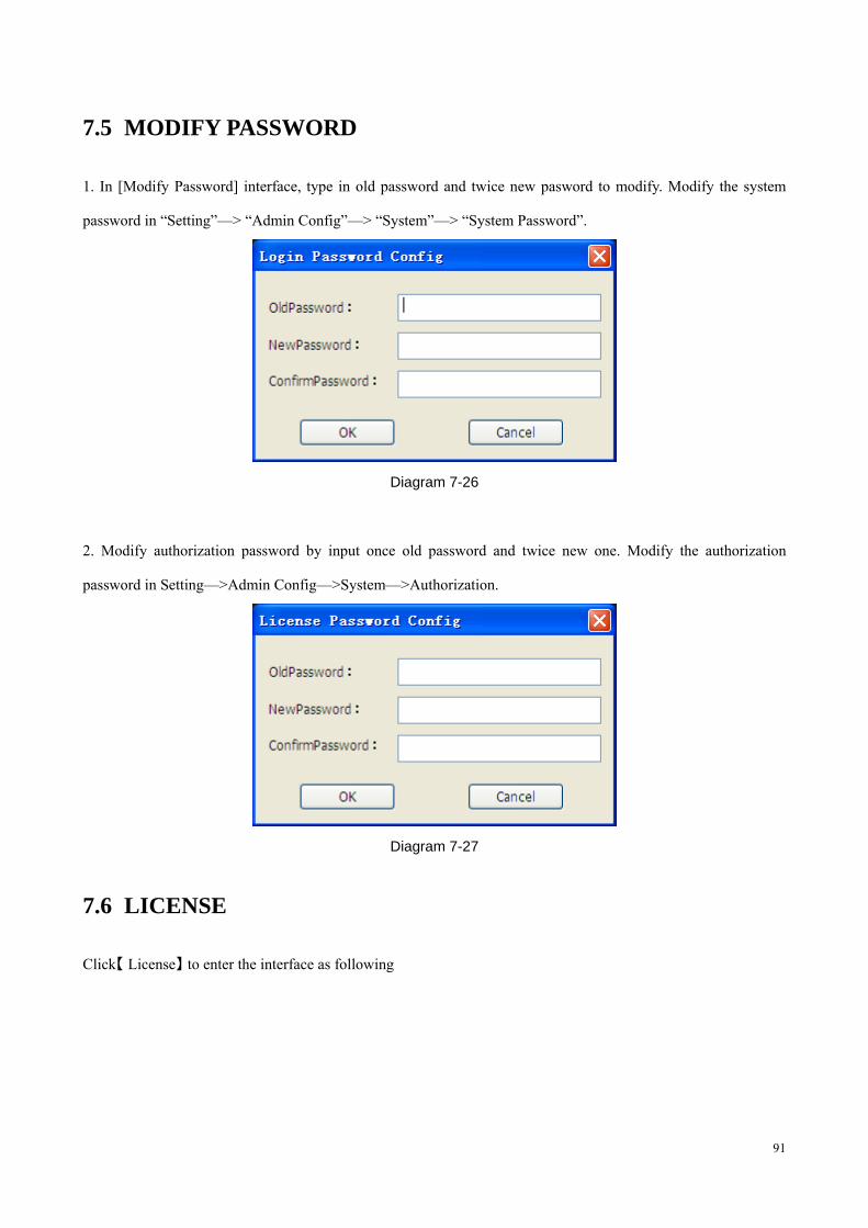
7.5 MODIFY PASSWORD
1. In [Modify Password] interface, type in old password and twice new pasword to modify. Modify the system
password in “Setting”—> “Admin Config”—> “System”—> “System Password”.
Diagram 7-26
2. Modify authorization password by input once old password and twice new one. Modify the authorization
password in Setting—>Admin Config—>System—>Authorization.
Diagram 7-27
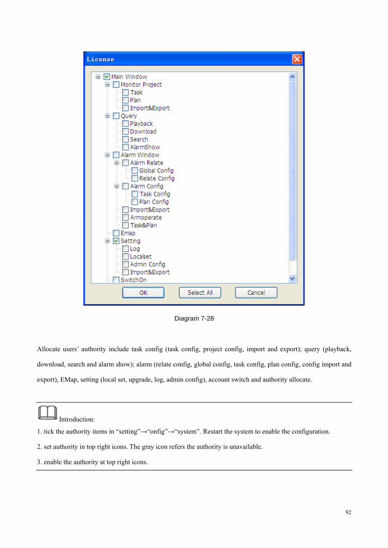
7.6 LICENSE
Click【 】License to enter the interface as following
92
Diagram 7-28
Allocate users’ authority include task config (task config, project config, import and export); query (playback,
download, search and alarm show); alarm (relate config, global config, task config, plan config, config import and
export), EMap, setting (local set, upgrade, log, admin config), account switch and authority allocate.
Introduction:
1. tick the authority items in “setting”→“onfig”→“system”. Restart the system to enable the configuration.
2. set authority in top right icons. The gray icon refers the authority is unavailable.
3. enable the authority at top right icons.
93
8 APPENDIX A
8.1 FAQ
Q: The prompt “Video Open Fail” shows in live view or tour mode?
A: Probably reasonss:
1. the device breakdown.
2. can not get the streaming because of the network state.
Q: P/T/Z is incontrollable?
A: Probably reasonss::
1. ensure the camera has P/T/Z function
2.enable the P/T/Z function
3.configurate the compatible protocal and address code, check the 485 line “+”“—”are correct.