Embed Size (px)
Citation preview

Manual # 99904532
IMT 6006i Technical Specifications & Parts
24v Model
Revised: February 27, 2018
IOWA MOLD TOOLING CO., INC.
PO Box 189 Garner, IA 50438
Tel: 641-923-3711 FAX: 641-923-2424 Website: http://www.imt.com
Copyright © 2018 Iowa Mold Tooling Co., Inc. All rights reserved
No part of this publication may be reproduced, stored in a retrieval system, or transmitted in any form or by any means, electronic, mechanical, photocopying, recording or otherwise without the prior written permission of Iowa Mold Tooling Co., Inc.
Iowa Mold Tooling Co., Inc. is an Oshkosh Corporation Company.

i
Contents
Revisions .................................................................................................................................................... iii
Electric Crane Introduction 5
Technical Specifications 7
6006i Technical Data .................................................................................................................................... 7 6006i Capacity Chart .................................................................................................................................... 9 Geometric Configuration ............................................................................................................................ 10 24V Pump & Motor Performance ............................................................................................................... 11
Crane Reference 13
Assemblies & Grease Zerk Locations ......................................................................................................... 13 6006i Recommended Spare Parts List ........................................................................................................ 14 General Body Installation (99904563) ........................................................................................................ 16 IMT-Manufactured Body Installation (99904525) ..................................................................................... 20 Telescopic Crane Orientation ..................................................................................................................... 28 Electric Crane Control ................................................................................................................................ 28
Parts 29
Parts Information ........................................................................................................................................ 30 Electric Crane Power Safety ....................................................................................................................... 32 Base & Mast Assembly (99904454) ........................................................................................................... 33 Valve Bank (73734375) .............................................................................................................................. 36 Cylinder, Lower (51721396) ...................................................................................................................... 37 Boom Assembly (99904335) ...................................................................................................................... 39 Light Kit (99906235) .................................................................................................................................. 45
99906235-1 ...................................................................................................................................... 46 99906235-2 ...................................................................................................................................... 47 99906235-3 ...................................................................................................................................... 48
Cylinder, Extension (51721386) ................................................................................................................. 49 2018 Crane & Winch Assembly (99904456) .............................................................................................. 51
99904456-1 ...................................................................................................................................... 52 99904456-2 ...................................................................................................................................... 53 99904456 Complete Parts List......................................................................................................... 54
Crane & Winch Assembly (99904456) Effective: 2-9-17 .................................................................... 56 99904456 Parts List ......................................................................................................................... 60
ii Contents
Cord Reel-6.7m, Electric 2-Wire (70735052) Effective: 2-9-17 ............................................................... 62 Cord Reel Assembly, 10’5” W/Packard Connector (51727065) Effective 2-9-17 ..................................... 63 Crane & Winch Assembly (99904456) ....................................................................................................... 64 Winch (71570911) ...................................................................................................................................... 69 Power Unit (73511181) .............................................................................................................................. 70 Electrical Installation (99904457) ............................................................................................................... 71 Protective Sleeve Installation (70034573) .................................................................................................. 73 275-Amp Contactor Replacement (99904578) ........................................................................................... 74 Controls Installation (99904377) ................................................................................................................ 75 Harness, Radio (77441270) ........................................................................................................................ 77 Harness, Tethered (77441269) .................................................................................................................... 79 Handle Assembly, Tethered (51721502) .................................................................................................... 80 Hydraulic Installation (99904458) Effective 5-18-15 ................................................................................. 83 6006i Decal Installation (95721549)........................................................................................................... 97
General Reference 99
Inspection Checklist .................................................................................................................................... 99 Deficiency / Recommendation / Corrective Action Report ...................................................................... 104 Thread Torque Chart (English) ................................................................................................................. 106 Thread Torque Chart (Metric) .................................................................................................................. 107 Turntable Bearing Thread Tightening Sequence ...................................................................................... 108 Turntable Bearing Inspection for Replacement ........................................................................................ 109
Contents iii
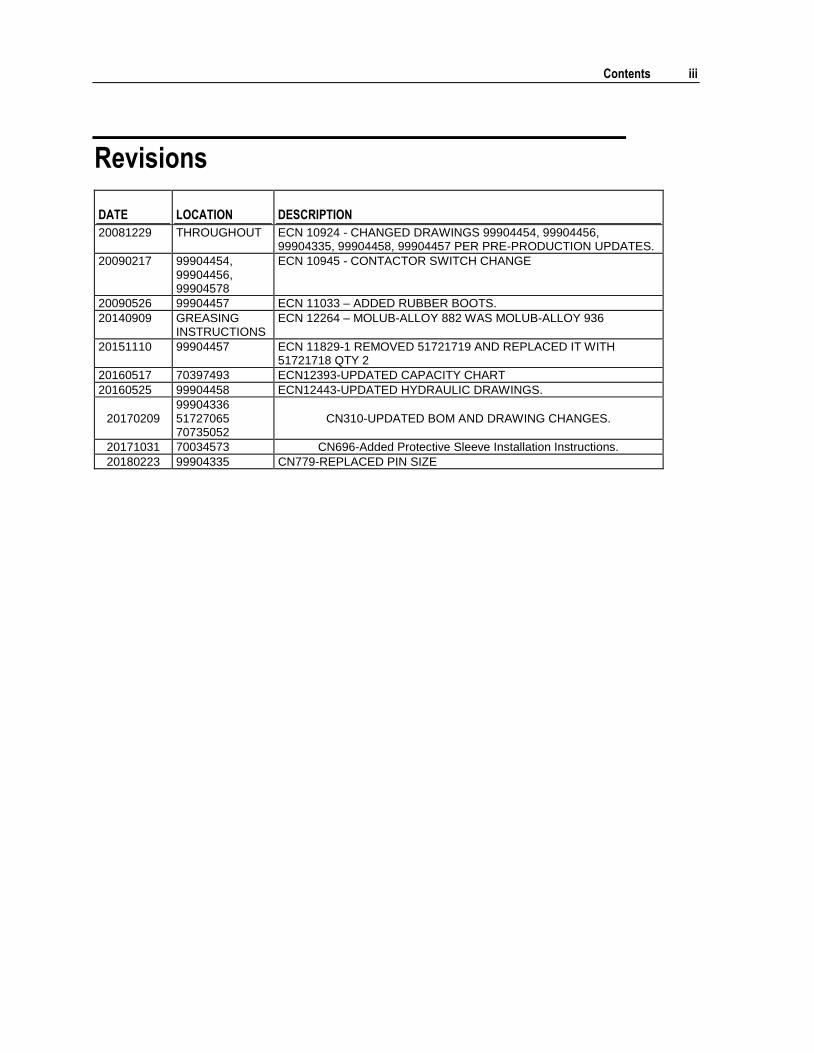
Revisions
DATE LOCATION DESCRIPTION
20081229 THROUGHOUT ECN 10924 - CHANGED DRAWINGS 99904454, 99904456, 99904335, 99904458, 99904457 PER PRE-PRODUCTION UPDATES.
20090217 99904454, 99904456, 99904578
ECN 10945 - CONTACTOR SWITCH CHANGE
20090526 99904457 ECN 11033 – ADDED RUBBER BOOTS.
20140909 GREASING INSTRUCTIONS
ECN 12264 – MOLUB-ALLOY 882 WAS MOLUB-ALLOY 936
20151110 99904457 ECN 11829-1 REMOVED 51721719 AND REPLACED IT WITH 51721718 QTY 2
20160517 70397493 ECN12393-UPDATED CAPACITY CHART
20160525 99904458 ECN12443-UPDATED HYDRAULIC DRAWINGS.
20170209 99904336 51727065 70735052
CN310-UPDATED BOM AND DRAWING CHANGES.
20171031 70034573 CN696-Added Protective Sleeve Installation Instructions.
20180223 99904335 CN779-REPLACED PIN SIZE

5
This volume deals with information applicable to your particular crane. For operating, maintenance and repair instructions, refer to IMT Electric Cranes Operation & Safety (IMT part number 99904381.)
We recommend that this volume be kept in a safe place in the office.
This manual is provided to assist you with ordering parts for your IMT crane. It also contains additional instructions regarding your particular installation.
It is the user’s responsibility to maintain and operate this unit in a manner that will result in the safest working conditions possible.
Warranty of this unit will be void on any part of the unit subjected to misuse due to overloading, abuse, lack of maintenance and unauthorized modifications. No warranty - verbal, written or implied - other than the official, published IMT new machinery and equipment warranty will be valid with this unit. In addition, it is also the user’s responsibility to be aware of existing Federal, State and Local codes and regulations governing the safe use and maintenance of this unit. This crane was designed and built to meet the standards of ANSI/ASME B30.5, Mobile & Locomotive Cranes. Contact the American Society of Mechanical Engineers (www.asme.org) for more information.
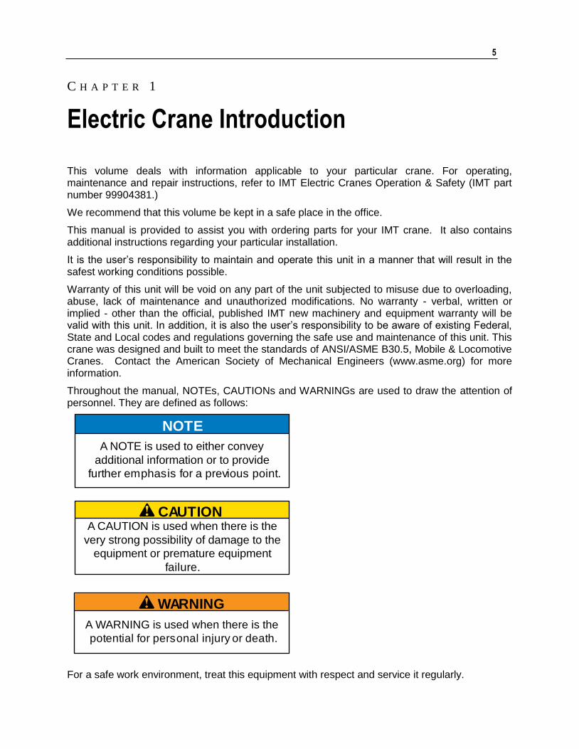
Throughout the manual, NOTEs, CAUTIONs and WARNINGs are used to draw the attention of personnel. They are defined as follows:
For a safe work environment, treat this equipment with respect and service it regularly.
C H A P T E R 1
Electric Crane Introduction
CAUTIONA CAUTION is used when there is the
very strong possibility of damage to the
equipment or premature equipment
failure.
WARNING
A WARNING is used when there is the
potential for personal injury or death.
NOTE
A NOTE is used to either convey
additional information or to provide
further emphasis for a previous point.

7
In This Chapter
6006i Technical Data ................................................................ 7 6006i Capacity Chart ................................................................ 9 Geometric Configuration ........................................................... 10 24V Pump & Motor Performance .............................................. 11
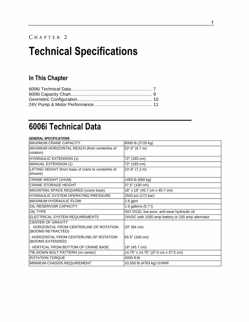
6006i Technical Data GENERAL SPECIFICATIONS
MAXIMUM CRANE CAPACITY 6000 lb (2720 kg)
MAXIMUM HORIZONTAL REACH (from centerline of rotation)
22'-0" (6.7 m)
HYDRAULIC EXTENSION (1) 72" (183 cm)
MANUAL EXTENSION (1) 72" (183 cm)
LIFTING HEIGHT (from base of crane to centerline of sheave)
23'-6" (7.2 m)
CRANE WEIGHT (1H1M) 1450 lb (660 kg)
CRANE STORAGE HEIGHT 37.5" (100 cm)
MOUNTING SPACE REQUIRED (crane base) 18" x 18" (45.7 cm x 45.7 cm)
HYDRAULIC SYSTEM OPERATING PRESSURE 2500 psi (172 bar)
MAXIMUM HYDRAULIC FLOW 2.6 gpm
OIL RESERVOIR CAPACITY 1.5 gallons (5.7 l)
OIL TYPE ISO VG32, low pour, anti-wear hydraulic oil
ELECTRICAL SYSTEM REQUIREMENTS 24VDC with 1000 amp battery or 100 amp alternator
CENTER OF GRAVITY
- HORIZONTAL FROM CENTERLINE OF ROTATION (BOOMS RETRACTED)
33" (84 cm)
- HORIZONTAL FROM CENTERLINE OF ROTATION (BOOMS EXTENDED)
65.5" (166 cm)
- VERTICAL FROM BOTTOM OF CRANE BASE 18" (45.7 cm)
TIE-DOWN BOLT PATTERN (on center) 14.75" x 14.75" (37.5 cm x 37.5 cm)
ROTATION TORQUE 4000 ft-lb
MINIMUM CHASSIS REQUIREMENT 10,500 lb (4763 kg) GVWR
C H A P T E R 2
Technical Specifications

8 IMT 6006i Technical Specifications & Parts Manual #99904532
CYLINDER SPECIFICATIONS
LOWER BOOM CYLINDER 4.5" bore, 21.43" stroke (11.4 cm bore, 54.4 cm stroke)
EXTENSION BOOM CYLINDER 2.5" bore; 72" stroke (6.4 cm bore; 183 cm stroke)
WINCH SPECIFICATIONS
FIRST WRAP LINE SPEED 11.5 ft/min (3.5 m/min)
THIRD WRAP LINE SPEED 14 ft/min (4.3 m/min)
ROPE DIAMETER 3/8" (9.6 mm)
WIRE ROPE LENGTH 80' (24.3 m)
CABLE BREAKING STRENGTH 15,100 lb (6,850 kg)
PERFORMANCE CHARACTERISTICS
ROTATION Continuous 360° (6.28 rad)
LOWER BOOM ELEVATION -5° to +75° (-0.1 to +1.3 rad)
EXTENSION CYLINDER 72" (1.8 m)
Chapter 2 Technical Specifications 9
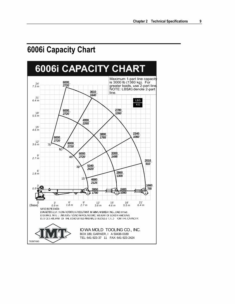
6006i Capacity Chart
IOWA MOLD TOOLING CO., INC.BOX 189, GARNER, I A 50438-0189
TEL: 641-923-37 11 FAX: 641-923-2424
15°
30°
45°
60°
75°
18'5.5 m
15'4.6 m
12'3.6 m
9'2.7 m
6'1.8 m
3'0.9 m
0(Base)
24'7.3 m
21'6.4 m
18'5.5 m
15'4.6 m
12'3.6 m
9'2.7 m
6'1.8 m
3'0.9 m
21'6.4 m
60002720
60002720
60002720
60002720
49902265
36101640
60002720
38901765
27801260
53402420
33001495
23401060
46802125
28601300
2010 910
39501790
24001090
1660 755
LBS
KG

10 IMT 6006i Technical Specifications & Parts Manual #99904532
Geometric Configuration
5'-10"(1.77 m)
4'-3"(1.30 m)
2'-9"(83.8 cm)
1'-7" (48.2 cm)
10'-0" (3.05 m)
16'-0" (4.88 m)
22'-0" (6.71 m)
23'-1"(7.03 m)
17'-3"(5.30 m)
11'-10"(3.60 m)
Chapter 2 Technical Specifications 11
24V Pump & Motor Performance
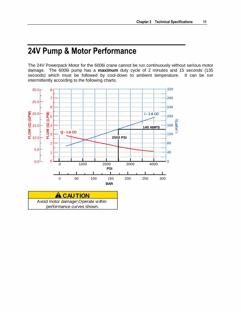
The 24V Powerpack Motor for the 6006i crane cannot be run continuously without serious motor damage. The 6006i pump has a maximum duty cycle of 2 minutes and 15 seconds (135 seconds) which must be followed by cool-down to ambient temperature. It can be run intermittently according to the following charts.
0 1000 2000 3000 4000
PSI
BAR
0 50 100 150 200 250 300
0
40
80
120
160
240
280
200
320
0
1
2
3
4
5
6
0.0
5.0
10.0
15.0
20.0
25.0
30.0
7
8
Q - 1.6 CC
I - 1.6 CC
140 AMPS
2500 PSI
CAUTIONAvoid motor damage! Operate w ithin
performance curves shown.
12 IMT 6006i Technical Specifications & Parts Manual #99904532
2.25 minutes
(2 min. 15 seconds)
140 amps
(Motor for 6006i)
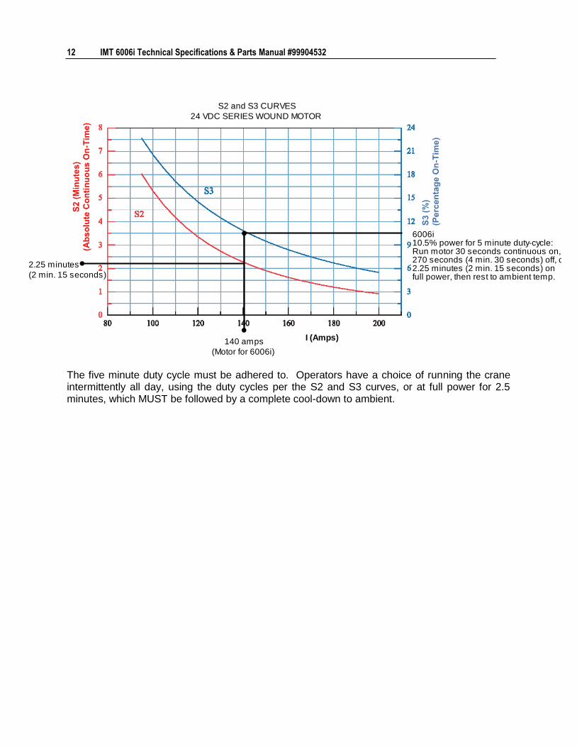
6006i10.5% power for 5 minute duty-cycle:Run motor 30 seconds continuous on,270 seconds (4 min. 30 seconds) off, or2.25 minutes (2 min. 15 seconds) onfull power, then rest to ambient temp.
I (Amps)
S2 and S3 CURVES
24 VDC SERIES WOUND MOTOR
The five minute duty cycle must be adhered to. Operators have a choice of running the crane intermittently all day, using the duty cycles per the S2 and S3 curves, or at full power for 2.5 minutes, which MUST be followed by a complete cool-down to ambient.
13
In This Chapter
Assemblies & Grease Zerk Locations ....................................... 13 6006i Recommended Spare Parts List ..................................... 14 General Body Installation (99904563) ...................................... 16 IMT-Manufactured Body Installation (99904525) ...................... 19 Telescopic Crane Orientation ................................................... 28 Electric Crane Control .............................................................. 28
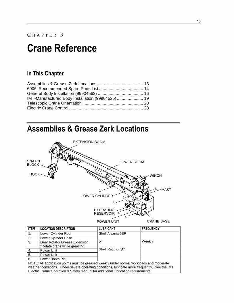
Assemblies & Grease Zerk Locations
54
6
CRANE BASE
WINCH
SNATCHBLOCK
MAST
POWER UNIT
LOWER BOOM
EXTENSION BOOM
HOOK
HYDRAULICRESERVOIR
LOWER CYLINDER
3
2
1
ITEM LOCATION DESCRIPTION LUBRICANT FREQUENCY
1. Lower Cylinder Rod Shell Alvania 2EP or Shell Retinax "A"
Weekly
2. Lower Cylinder Base
3. Gear Rotator Grease Extension *Rotate crane while greasing.
4. Power Unit
5. Power Unit
6. Lower Boom Pin
NOTE: All application points must be greased weekly under normal workloads and moderate weather conditions. Under severe operating conditions, lubricate more frequently. See the IMT Electric Crane Operation & Safety manual for additional lubrication requirements.
C H A P T E R 3
Crane Reference
14 IMT 6006i Technical Specifications & Parts Manual #99904532
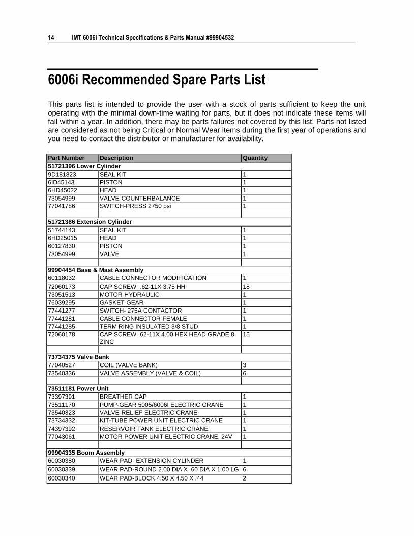
6006i Recommended Spare Parts List
This parts list is intended to provide the user with a stock of parts sufficient to keep the unit operating with the minimal down-time waiting for parts, but it does not indicate these items will fail within a year. In addition, there may be parts failures not covered by this list. Parts not listed are considered as not being Critical or Normal Wear items during the first year of operations and you need to contact the distributor or manufacturer for availability.
Part Number Description Quantity
51721396 Lower Cylinder
9D181823 SEAL KIT 1
6ID45143 PISTON 1
6HD45022 HEAD 1
73054999 VALVE-COUNTERBALANCE 1
77041786 SWITCH-PRESS 2750 psi 1
51721386 Extension Cylinder
51744143 SEAL KIT 1
6HD25015 HEAD 1
60127830 PISTON 1
73054999 VALVE 1
99904454 Base & Mast Assembly
60118032 CABLE CONNECTOR MODIFICATION 1
72060173 CAP SCREW .62-11X 3.75 HH 18
73051513 MOTOR-HYDRAULIC 1
76039295 GASKET-GEAR 1
77441277 SWITCH- 275A CONTACTOR 1
77441281 CABLE CONNECTOR-FEMALE 1
77441285 TERM RING INSULATED 3/8 STUD 1
72060178 CAP SCREW .62-11X 4.00 HEX HEAD GRADE 8 ZINC
15
73734375 Valve Bank
77040527 COIL (VALVE BANK) 3
73540336 VALVE ASSEMBLY (VALVE & COIL) 6
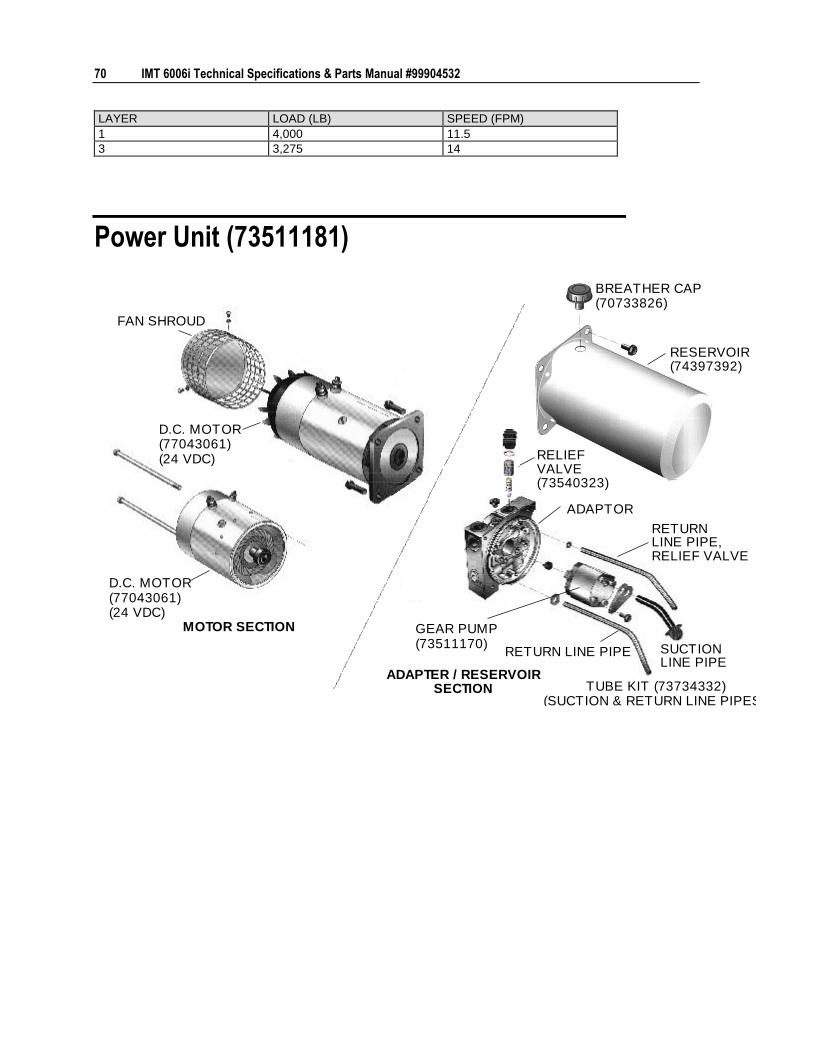
73511181 Power Unit
73397391 BREATHER CAP 1
73511170 PUMP-GEAR 5005/6006I ELECTRIC CRANE 1
73540323 VALVE-RELIEF ELECTRIC CRANE 1
73734332 KIT-TUBE POWER UNIT ELECTRIC CRANE 1
74397392 RESERVOIR TANK ELECTRIC CRANE 1
77043061 MOTOR-POWER UNIT ELECTRIC CRANE, 24V 1
99904335 Boom Assembly
60030380 WEAR PAD- EXTENSION CYLINDER 1
60030339 WEAR PAD-ROUND 2.00 DIA X .60 DIA X 1.00 LG 6
60030340 WEAR PAD-BLOCK 4.50 X 4.50 X .44 2

Chapter 3 Crane Reference 15
Part Number Description Quantity
60030341 WEAR PAD-BLOCK 4.50 X 3.50 X .44 2
60133062 WEAR PAD-ROUND 1.00 DIA X .62 DIA X .81L 2
60132302 STOP SCREW 3/8-24 X .50 2
72661514 PIN-LOCK W/HANDLE .875 X 4.25 1
70144211 PIN- .75X 6.50 LONG 1
99904456 Crane & Winch Assembly
51720302 CORD REEL ASSEMBLY 1
70580182 WIRE ROPE ASSEMBLY 1
71413196 SPRING-.105WIRE 0.75OD 2.875 LG 1
72601798 WASHER-LOCK 12MM 4
72601935 CAP SCREW M12-1.75X 40 SOCKET-HEAD PLAIN
4
72601938 BOLT-EYE # 8-32X .75 1
77041459 SWITCH-LIMIT 1
77441096 CONNECTOR- .50 STRAIN RELIEF .25-.38 1
16 IMT 6006i Technical Specifications & Parts Manual #99904532
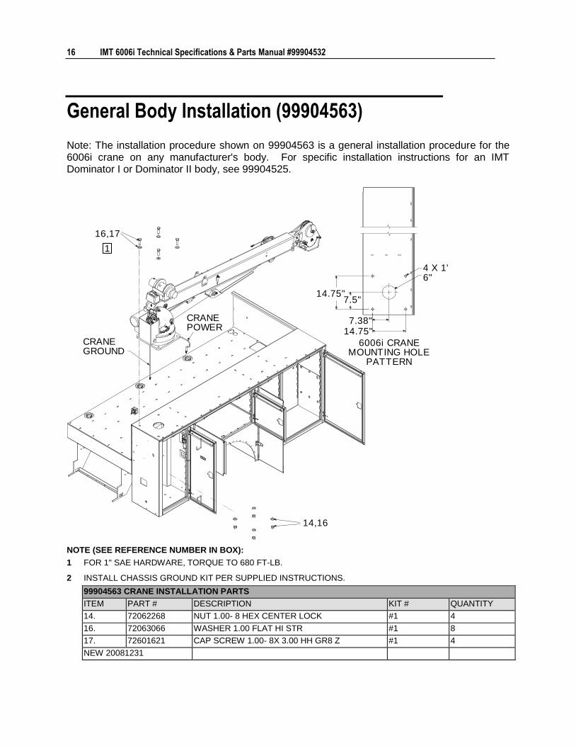
General Body Installation (99904563)
Note: The installation procedure shown on 99904563 is a general installation procedure for the 6006i crane on any manufacturer's body. For specific installation instructions for an IMT Dominator I or Dominator II body, see 99904525.
14,16
7.38"
6006i CRANEMOUNTING HOLE
PATTERN
14.75"
14.75"7.5"
6"4 X 1"
CRANEPOWER
1
16,17
CRANEGROUND
NOTE (SEE REFERENCE NUMBER IN BOX):
1 FOR 1" SAE HARDWARE, TORQUE TO 680 FT-LB.
2 INSTALL CHASSIS GROUND KIT PER SUPPLIED INSTRUCTIONS.
99904563 CRANE INSTALLATION PARTS
ITEM PART # DESCRIPTION KIT # QUANTITY
14. 72062268 NUT 1.00- 8 HEX CENTER LOCK #1 4
16. 72063066 WASHER 1.00 FLAT HI STR #1 8
17. 72601621 CAP SCREW 1.00- 8X 3.00 HH GR8 Z #1 4
NEW 20081231
Chapter 3 Crane Reference 17
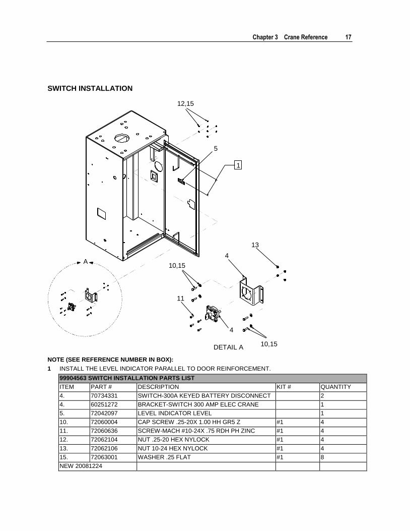
SWITCH INSTALLATION
A
5
4
13
4
11
DETAIL A10,15
10,15
1
12,15
NOTE (SEE REFERENCE NUMBER IN BOX):
1 INSTALL THE LEVEL INDICATOR PARALLEL TO DOOR REINFORCEMENT.
99904563 SWITCH INSTALLATION PARTS LIST
ITEM PART # DESCRIPTION KIT # QUANTITY
4. 70734331 SWITCH-300A KEYED BATTERY DISCONNECT 2
4. 60251272 BRACKET-SWITCH 300 AMP ELEC CRANE 1
5. 72042097 LEVEL INDICATOR LEVEL 1
10. 72060004 CAP SCREW .25-20X 1.00 HH GR5 Z #1 4
11. 72060636 SCREW-MACH #10-24X .75 RDH PH ZINC #1 4
12. 72062104 NUT .25-20 HEX NYLOCK #1 4
13. 72062106 NUT 10-24 HEX NYLOCK #1 4
15. 72063001 WASHER .25 FLAT #1 8
NEW 20081224

18 IMT 6006i Technical Specifications & Parts Manual #99904532
ELECTRICAL SCHEMATIC
G
H
C
A
D
F
E
4 9 7 8
6 6
TO CRANEPOWER
TO CRANEGROUND
NEG-
POS+
AUXILIARYBATTERY
NEG-
POS+
TRUCKBATTERY
NEG-
POS+
TRUCKBATTERY
NEG-
POS+
AUXILIARYBATTERY
NOTES:
1 TRUCK AND AUXILIARY BATTERIES MUST BE IDENTICAL 12V 1,000 CCA.
2 HEAT SHRINK ALL CABLE ENDS: RED (POSITIVE +), BLACK (NEGATIVE -)
3 WRAP CABLES WHICH PASS THROUGH EXPOSED SHEET METAL WITH LOOM.
4 INSTALL CHASSIS GROUND PER SUPPLIED INSTRUCTIONS.
WIRE CIRCUIT WIRE DESCRIPTION
C POWER UNIT MOTOR GROUND #1 CABLE, 2-FT LONG, BLACK 3/8-RING TERMINAL
H TRUCK BATTERY GROUND #1 CABLE, 2-FT LONG, BLACK 3/8-RING TERMINAL
G AUXILIARY BATTERY GROUND #1 CABLE, 2-FT LONG, BLACK 3/8-RING TERMINAL
A ON-OFF SWITCH (CRANE SIDE) 14 GA WIRE, 2-FT LONG, WHITE 3/8-RING TERMINAL
E TRUCK BATTERY POSITIVE #1 CABLE, 2-FT LONG, RED 3/8-RING TERMINAL
F AUXILIARY BATTERY POSITIVE #1 CABLE, 2-FT LONG, RED 3/8-RING TERMINAL
D ON-OFF SWITCH POSITIVE #1 CABLE, 2-FT LONG, RED 3/8 RING TERMINAL
Chapter 3 Crane Reference 19
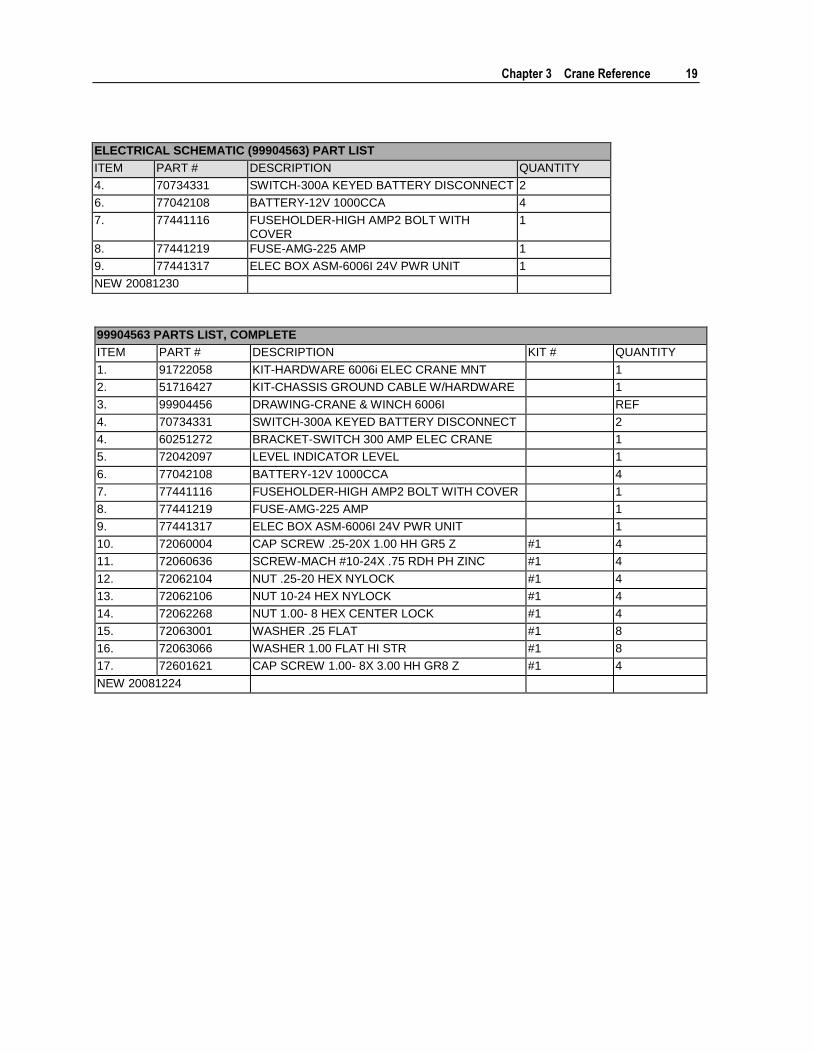
ELECTRICAL SCHEMATIC (99904563) PART LIST
ITEM PART # DESCRIPTION QUANTITY
4. 70734331 SWITCH-300A KEYED BATTERY DISCONNECT 2
6. 77042108 BATTERY-12V 1000CCA 4
7. 77441116 FUSEHOLDER-HIGH AMP2 BOLT WITH COVER
1
8. 77441219 FUSE-AMG-225 AMP 1
9. 77441317 ELEC BOX ASM-6006I 24V PWR UNIT 1
NEW 20081230
99904563 PARTS LIST, COMPLETE
ITEM PART # DESCRIPTION KIT # QUANTITY
1. 91722058 KIT-HARDWARE 6006i ELEC CRANE MNT 1
2. 51716427 KIT-CHASSIS GROUND CABLE W/HARDWARE 1
3. 99904456 DRAWING-CRANE & WINCH 6006I REF
4. 70734331 SWITCH-300A KEYED BATTERY DISCONNECT 2
4. 60251272 BRACKET-SWITCH 300 AMP ELEC CRANE 1
5. 72042097 LEVEL INDICATOR LEVEL 1
6. 77042108 BATTERY-12V 1000CCA 4
7. 77441116 FUSEHOLDER-HIGH AMP2 BOLT WITH COVER 1
8. 77441219 FUSE-AMG-225 AMP 1
9. 77441317 ELEC BOX ASM-6006I 24V PWR UNIT 1
10. 72060004 CAP SCREW .25-20X 1.00 HH GR5 Z #1 4
11. 72060636 SCREW-MACH #10-24X .75 RDH PH ZINC #1 4
12. 72062104 NUT .25-20 HEX NYLOCK #1 4
13. 72062106 NUT 10-24 HEX NYLOCK #1 4
14. 72062268 NUT 1.00- 8 HEX CENTER LOCK #1 4
15. 72063001 WASHER .25 FLAT #1 8
16. 72063066 WASHER 1.00 FLAT HI STR #1 8
17. 72601621 CAP SCREW 1.00- 8X 3.00 HH GR8 Z #1 4
NEW 20081224
20 IMT 6006i Technical Specifications & Parts Manual #99904532
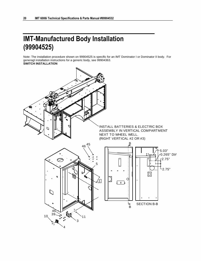
IMT-Manufactured Body Installation (99904525) Note: The installation procedure shown on 99904525 is specific for an IMT Dominator I or Dominator II body. For generagl installation instructions for a generic body, see 99904363. SWITCH INSTALLATION
B
B
4
103946
3
5
4546
11
1
1"5.03"0.265" DIA
2.75"
2.75"
SECTION B-B
INSTALL BATTERIES & ELECTRIC BOX
ASSEMBLY IN VERTICAL COMPARTMENT
NEXT TO WHEEL WELL.
(RIGHT VERTICAL #2 OR #3)
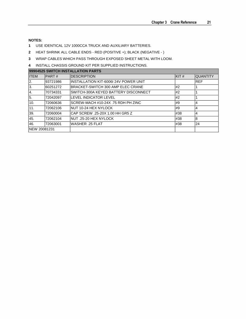
Chapter 3 Crane Reference 21
NOTES:
1 USE IDENTICAL 12V 1000CCA TRUCK AND AUXILIARY BATTERIES.
2 HEAT SHRINK ALL CABLE ENDS - RED (POSITIVE +); BLACK (NEGATIVE - )
3 WRAP CABLES WHICH PASS THROUGH EXPOSED SHEET METAL WITH LOOM.
4 INSTALL CHASSIS GROUND KIT PER SUPPLIED INSTRUCTIONS.
99904525 SWITCH INSTALLATION PARTS
ITEM PART # DESCRIPTION KIT # QUANTITY
2. 93721986 INSTALLATION KIT-6006I 24V POWER UNIT REF
3. 60251272 BRACKET-SWITCH 300 AMP ELEC CRANE #2 1
4. 70734331 SWITCH-300A KEYED BATTERY DISCONNECT #2 1
5. 72042097 LEVEL INDICATOR LEVEL #2 1
10. 72060636 SCREW-MACH #10-24X .75 RDH PH ZINC #9 4
11. 72062106 NUT 10-24 HEX NYLOCK #9 4
39. 72060004 CAP SCREW .25-20X 1.00 HH GR5 Z #38 4
45. 72062104 NUT .25-20 HEX NYLOCK #38 8
46. 72063001 WASHER .25 FLAT #38 24
NEW 20081231

22 IMT 6006i Technical Specifications & Parts Manual #99904532
24-VOLT POWER SOURCE INSTALLATION
1923
2222
4749
41
46
42 23 23
2222
22
16
8
4648
4217
24
30
2526
27
29
28
43
49
18, 42, 45,
46(2)12V
1000CCAAUXILIARYBATTERIES
99904525 POWER SOURCE INSTALLATION PARTS
ITEM PART # DESCRIPTION KIT # QUANTITY
1. 99904456 DRAWING-CRANE & WINCH 6006I REF
2. 93721986 INSTALLATION KIT-6006I 24V POWER UNIT REF
8. 77441317 ELEC BOX ASSEMBLY-6006I 24V PWR UNIT #2 1
15. 93721987 INSTALLATION KIT-6006i 24V POWER UNIT IMT BODY 1
16. 51722054 -SHELF KIT 1.50 V2 11 - V3 13-14 #15 1
17. 52722053 WELDMENT-BATTERY HOLD DOWN #15 1
18. 60119069 ROD-THREADED .25-20 X 9.25 #15 4
19. 60251273 PANEL-CRANE BOX VALVE BLOCK DELETE #15 1
22. 77041773 STUD-BULKHEAD PASS THRU 3/8" RED #15 5
23. 77041774 STUD-BULKHEAD PASS THRU 3/8" BLACK #15 3
24. 77042108 BATTERY-12V 1000CCA #15 2
25. 77441318 CABLE ASSEMBLY- 1GA-3/8RNGX 3/8RNGX 9.00LG BLK #15 1
26. 77441319 CABLE ASSEMBLY- 1GA-3/8RNGX 3/8RNGX 9.00LG RED #15 1
27. 77441320 TERMINAL INSULATED 3/8 STUD RED #15 1
28. 77441321 TERMINAL INSULATED 3/8 STUD BLK #15 1
29. 77441322 TERMINAL INSULATED 3/8 STUD RED DUAL CABLES #15 1
30. 77441323 TERMINAL INSULATED 3/8 STUD BLK DUAL CABLES #15 1
41. 72060047 CAP SCREW .38-16X 1.25 HH GR5 Z #38 2
42. 72062000 NUT .25-20 HEX #38 12
43. 72062002 NUT .38-16 HEX #38 4
45. 72062104 NUT .25-20 HEX NYLOCK #38 8
46. 72063001 WASHER .25 FLAT #38 24
47. 72063003 WASHER .38 FLAT #38 10
48. 72063049 WASHER .25 LOCK #38 4
49. 72063051 WASHER .38 LOCK #38 6
NEW 20081231
Chapter 3 Crane Reference 23
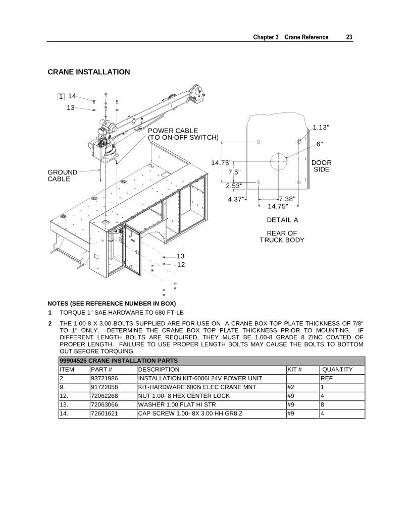
CRANE INSTALLATION
14
13
13
12
DETAIL A
REAR OFTRUCK BODY
DOORSIDE
6"
14.75"7.38"4.37"
2.53"
7.5"
14.75"
1.13"POWER CABLE(TO ON-OFF SWITCH)
GROUNDCABLE
1
NOTES (SEE REFERENCE NUMBER IN BOX)
1 TORQUE 1" SAE HARDWARE TO 680 FT-LB
2 THE 1.00-8 X 3.00 BOLTS SUPPLIED ARE FOR USE ON A CRANE BOX TOP PLATE THICKNESS OF 7/8" TO 1" ONLY. DETERMINE THE CRANE BOX TOP PLATE THICKNESS PRIOR TO MOUNTING. IF DIFFERENT LENGTH BOLTS ARE REQUIRED, THEY MUST BE 1.00-8 GRADE 8 ZINC COATED OF PROPER LENGTH. FAILURE TO USE PROPER LENGTH BOLTS MAY CAUSE THE BOLTS TO BOTTOM OUT BEFORE TORQUING.
99904525 CRANE INSTALLATION PARTS
ITEM PART # DESCRIPTION KIT # QUANTITY
2. 93721986 INSTALLATION KIT-6006I 24V POWER UNIT REF
9. 91722058 KIT-HARDWARE 6006i ELEC CRANE MNT #2 1
12. 72062268 NUT 1.00- 8 HEX CENTER LOCK #9 4
13. 72063066 WASHER 1.00 FLAT HI STR #9 8
14. 72601621 CAP SCREW 1.00- 8X 3.00 HH GR8 Z #9 4
24 IMT 6006i Technical Specifications & Parts Manual #99904532
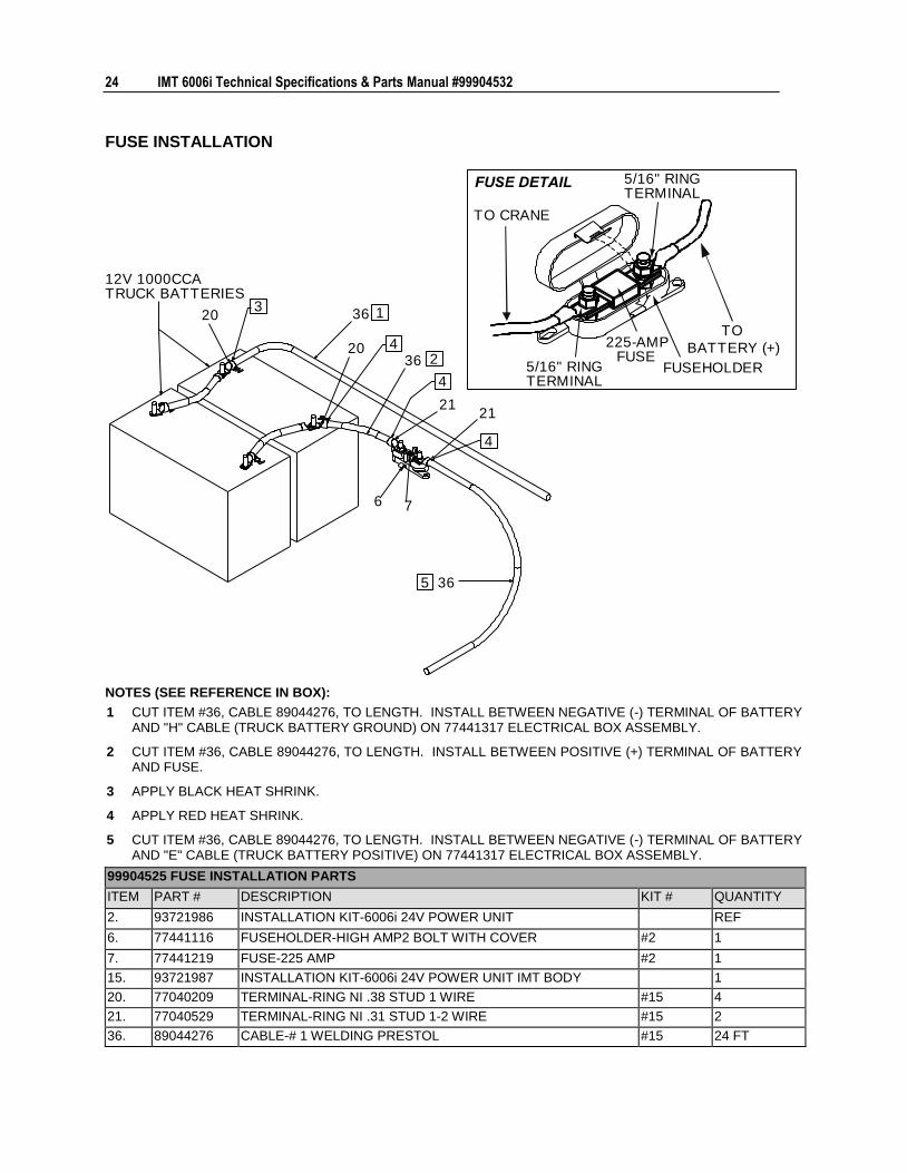
FUSE INSTALLATION
6
2121
7
20
20
36
36
36FUSEHOLDER
TO
BATTERY (+)
12V 1000CCATRUCK BATTERIES
1
2
3
4
4
4
5
TO CRANE
5/16" RINGTERMINAL
5/16" RINGTERMINAL
225-AMPFUSE
NOTES (SEE REFERENCE IN BOX):
1 CUT ITEM #36, CABLE 89044276, TO LENGTH. INSTALL BETWEEN NEGATIVE (-) TERMINAL OF BATTERY AND "H" CABLE (TRUCK BATTERY GROUND) ON 77441317 ELECTRICAL BOX ASSEMBLY.
2 CUT ITEM #36, CABLE 89044276, TO LENGTH. INSTALL BETWEEN POSITIVE (+) TERMINAL OF BATTERY AND FUSE.
3 APPLY BLACK HEAT SHRINK.
4 APPLY RED HEAT SHRINK.
5 CUT ITEM #36, CABLE 89044276, TO LENGTH. INSTALL BETWEEN NEGATIVE (-) TERMINAL OF BATTERY AND "E" CABLE (TRUCK BATTERY POSITIVE) ON 77441317 ELECTRICAL BOX ASSEMBLY.
99904525 FUSE INSTALLATION PARTS
ITEM PART # DESCRIPTION KIT # QUANTITY
2. 93721986 INSTALLATION KIT-6006i 24V POWER UNIT REF
6. 77441116 FUSEHOLDER-HIGH AMP2 BOLT WITH COVER #2 1
7. 77441219 FUSE-225 AMP #2 1
15. 93721987 INSTALLATION KIT-6006i 24V POWER UNIT IMT BODY 1
20. 77040209 TERMINAL-RING NI .38 STUD 1 WIRE #15 4
21. 77040529 TERMINAL-RING NI .31 STUD 1-2 WIRE #15 2
36. 89044276 CABLE-# 1 WELDING PRESTOL #15 24 FT
Chapter 3 Crane Reference 25
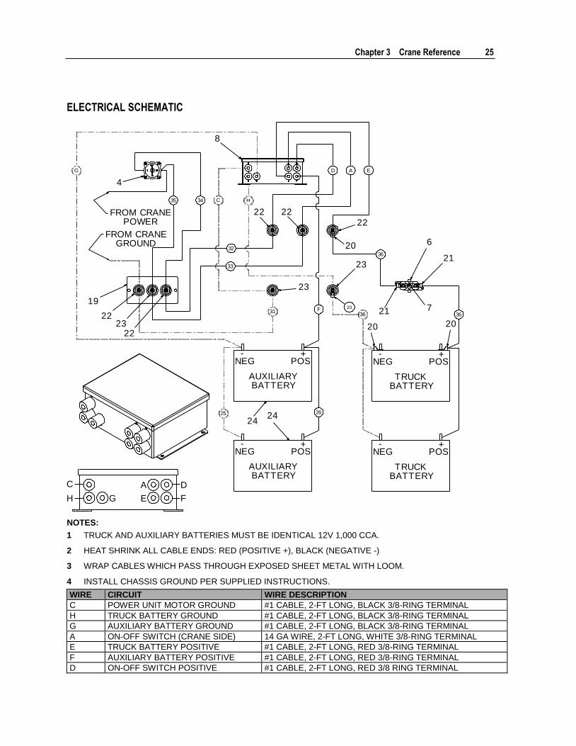
ELECTRICAL SCHEMATIC
A
33
35 C
31
D
34
32
E
36
36
H
36F
26
G
25
6
7
21
21
20 20
23
20
20
22
2222
23
2424
19
2223
22
4
8
-NEG
+POS
AUXILIARYBATTERY
-NEG
+POS
AUXILIARYBATTERY
-NEG
+POS
TRUCKBATTERY
-NEG
+POS
TRUCKBATTERY
FROM CRANEPOWER
FROM CRANEGROUND
A D
E F
C
H G
NOTES:
1 TRUCK AND AUXILIARY BATTERIES MUST BE IDENTICAL 12V 1,000 CCA.
2 HEAT SHRINK ALL CABLE ENDS: RED (POSITIVE +), BLACK (NEGATIVE -)
3 WRAP CABLES WHICH PASS THROUGH EXPOSED SHEET METAL WITH LOOM.
4 INSTALL CHASSIS GROUND PER SUPPLIED INSTRUCTIONS.
WIRE CIRCUIT WIRE DESCRIPTION
C POWER UNIT MOTOR GROUND #1 CABLE, 2-FT LONG, BLACK 3/8-RING TERMINAL
H TRUCK BATTERY GROUND #1 CABLE, 2-FT LONG, BLACK 3/8-RING TERMINAL
G AUXILIARY BATTERY GROUND #1 CABLE, 2-FT LONG, BLACK 3/8-RING TERMINAL
A ON-OFF SWITCH (CRANE SIDE) 14 GA WIRE, 2-FT LONG, WHITE 3/8-RING TERMINAL
E TRUCK BATTERY POSITIVE #1 CABLE, 2-FT LONG, RED 3/8-RING TERMINAL
F AUXILIARY BATTERY POSITIVE #1 CABLE, 2-FT LONG, RED 3/8-RING TERMINAL
D ON-OFF SWITCH POSITIVE #1 CABLE, 2-FT LONG, RED 3/8 RING TERMINAL
26 IMT 6006i Technical Specifications & Parts Manual #99904532
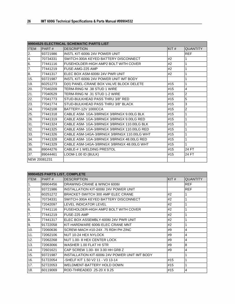
99904525 ELECTRICAL SCHEMATIC PARTS LIST
ITEM PART # DESCRIPTION KIT # QUANTITY
2. 93721986 INSTL KIT-6006i 24V POWER UNIT REF
4. 70734331 SWITCH-300A KEYED BATTERY DISCONNECT #2 1
6. 77441116 FUSEHOLDER-HIGH AMP2 BOLT WITH COVER #2 1
7. 77441219 FUSE-AMG-225 AMP #2 1
8. 77441317 ELEC BOX ASM-6006I 24V PWR UNIT #2 1
15. 93721987 INSTL KIT-6006i 24V POWER UNIT IMT BODY 1
19. 60251273 D(II) PANEL-CRANE BOX VALVE BLOCK DELETE #15 1
20. 77040209 TERM-RING NI .38 STUD 1 WIRE #15 4
21. 77040529 TERM-RING NI .31 STUD 1-2 WIRE #15 2
22. 77041773 STUD-BULKHEAD PASS THRU 3/8" RED #15 5
23. 77041774 STUD-BULKHEAD PASS THRU 3/8" BLACK #15 3
24. 77042108 BATTERY-12V 1000CCA #15 2
25. 77441318 CABLE ASM- 1GA-3/8RNGX 3/8RNGX 9.00LG BLK #15 1
26. 77441319 CABLE ASM- 1GA-3/8RNGX 3/8RNGX 9.00LG RED #15 1
31. 77441324 CABLE ASM- 1GA-3/8RNGX 3/8RNGX 110.00LG BLK #15 1
32. 77441325 CABLE ASM- 1GA-3/8RNGX 3/8RNGX 110.00LG RED #15 1
33. 77441326 CABLE ASM-14GA-3/8RNGX 3/8RNGX 110.00LG WHT #15 1
34. 77441328 CABLE ASM- 1GA-3/8RNGX 3/8RNGX 48.00LG RED #15 1
35. 77441329 CABLE ASM-14GA-3/8RNGX 3/8RNGX 48.00LG WHT #15 1
36. 89044276 CABLE-# 1 WELDING PRESTOL #15 24 FT
37. 89044461 LOOM-1.00 ID (BULK) #15 24 FT
NEW 20081231
99904525 PARTS LIST, COMPLETE
ITEM PART # DESCRIPTION KIT # QUANTITY
1. 99904456 DRAWING-CRANE & WINCH 6006I REF
2. 93721986 INSTALLATION KIT-6006I 24V POWER UNIT REF
3. 60251272 BRACKET-SWITCH 300 AMP ELEC CRANE #2 1
4. 70734331 SWITCH-300A KEYED BATTERY DISCONNECT #2 1
5. 72042097 LEVEL INDICATOR LEVEL #2 1
6. 77441116 FUSEHOLDER-HIGH AMP2 BOLT WITH COVER #2 1
7. 77441219 FUSE-225 AMP #2 1
8. 77441317 ELEC BOX ASSEMBLY-6006I 24V PWR UNIT #2 1
9. 91722058 KIT-HARDWARE 6006i ELEC CRANE MNT #2 1
10. 72060636 SCREW-MACH #10-24X .75 RDH PH ZINC #9 4
11. 72062106 NUT 10-24 HEX NYLOCK #9 4
12. 72062268 NUT 1.00- 8 HEX CENTER LOCK #9 4
13. 72063066 WASHER 1.00 FLAT HI STR #9 8
14. 72601621 CAP SCREW 1.00- 8X 3.00 HH GR8 Z #9 4
15. 93721987 INSTALLATION KIT-6006i 24V POWER UNIT IMT BODY 1
16. 51722054 -SHELF KIT 1.50 V2 11 - V3 13-14 #15 1
17. 52722053 WELDMENT-BATTERY HOLD DOWN #15 1
18. 60119069 ROD-THREADED .25-20 X 9.25 #15 4

Chapter 3 Crane Reference 27
99904525 PARTS LIST, COMPLETE
ITEM PART # DESCRIPTION KIT # QUANTITY
19. 60251273 PANEL-CRANE BOX VALVE BLOCK DELETE #15 1
20. 77040209 TERMINAL-RING NI .38 STUD 1 WIRE #15 4
21. 77040529 TERMINAL-RING NI .31 STUD 1-2 WIRE #15 2
22. 77041773 STUD-BULKHEAD PASS THRU 3/8" RED #15 5
23. 77041774 STUD-BULKHEAD PASS THRU 3/8" BLACK #15 3
24. 77042108 BATTERY-12V 1000CCA #15 2
25. 77441318 CABLE ASSEMBLY- 1GA-3/8RNGX 3/8RNGX 9.00LG BLK #15 1
26. 77441319 CABLE ASSEMBLY- 1GA-3/8RNGX 3/8RNGX 9.00LG RED #15 1
27. 77441320 TERMINAL INSULATED 3/8 STUD RED #15 1
28. 77441321 TERMINAL INSULATED 3/8 STUD BLK #15 1
29. 77441322 TERMINAL INSULATED 3/8 STUD RED DUAL CABLES #15 1
30. 77441323 TERMINAL INSULATED 3/8 STUD BLK DUAL CABLES #15 1
31. 77441324 CABLE ASSEMBLY- 1GA-3/8RNGX 3/8RNGX 110.00LG BLK #15 1
32. 77441325 CABLE ASSEMBLY- 1GA-3/8RNGX 3/8RNGX 110.00LG RED #15 1
33. 77441326 CABLE ASSEMBLY-14GA-3/8RNGX 3/8RNGX 110.00LG WHT #15 1
34. 77441328 CABLE ASSEMBLY- 1GA-3/8RNGX 3/8RNGX 48.00LG RED #15 1
35. 77441329 CABLE ASSEMBLY-14GA-3/8RNGX 3/8RNGX 48.00LG WHT #15 1
36. 89044276 CABLE-# 1 WELDING PRESTOL #15 24 FT
37. 89044461 LOOM-1.00 ID (BULK) #15 24 FT
38. 91722057 KIT-HARDWARE 6006i ELEC CRANE BODY INSTALLATION 1
39. 72060004 CAP SCREW .25-20X 1.00 HH GR5 Z #38 4
40. 72060046 CAP SCREW .38-16X 1.00 HH GR5 Z #38 4
41. 72060047 CAP SCREW .38-16X 1.25 HH GR5 Z #38 2
42. 72062000 NUT .25-20 HEX #38 12
43. 72062002 NUT .38-16 HEX #38 4
44. 72062103 NUT .38-16 HEX NYLOCK #38 4
45. 72062104 NUT .25-20 HEX NYLOCK #38 8
46. 72063001 WASHER .25 FLAT #38 24
47. 72063003 WASHER .38 FLAT #38 10
48. 72063049 WASHER .25 LOCK #38 4
49. 72063051 WASHER .38 LOCK #38 6
NEW 20081231
28 IMT 6006i Technical Specifications & Parts Manual #99904532
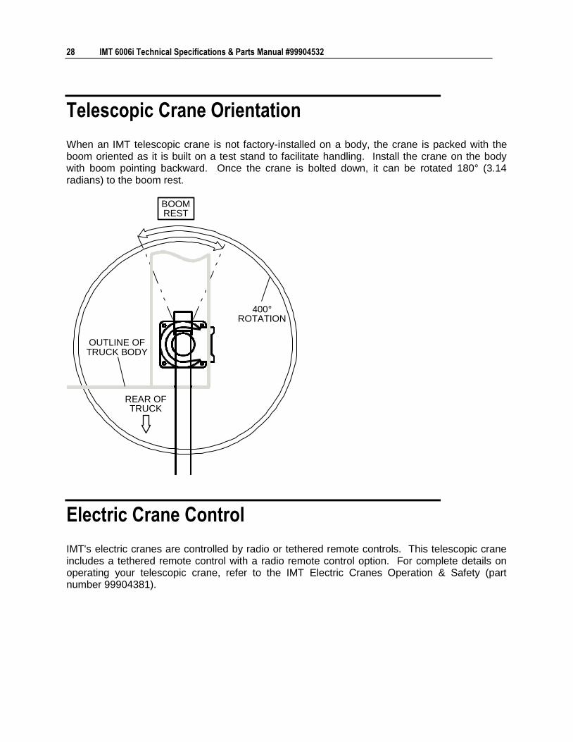
Telescopic Crane Orientation
When an IMT telescopic crane is not factory-installed on a body, the crane is packed with the boom oriented as it is built on a test stand to facilitate handling. Install the crane on the body with boom pointing backward. Once the crane is bolted down, it can be rotated 180° (3.14 radians) to the boom rest.
400°ROTATION
OUTLINE OFTRUCK BODY
REAR OFTRUCK
BOOMREST
Electric Crane Control
IMT's electric cranes are controlled by radio or tethered remote controls. This telescopic crane includes a tethered remote control with a radio remote control option. For complete details on operating your telescopic crane, refer to the IMT Electric Cranes Operation & Safety (part number 99904381).
29
In This Chapter
Parts Information ...................................................................... 30 Electric Crane Power Safety ..................................................... 32 Base & Mast Assembly (99904454).......................................... 33 Valve Bank (73734375) ............................................................ 36 Cylinder, Lower (51721396) ..................................................... 37 Boom Assembly (99904335) .................................................... 42 Cylinder, Extension (51721386) ............................................... 44 Crane & Winch Assembly (99904456) ...................................... 50 Winch (71570911) .................................................................... 68 Power Unit (73511181)............................................................. 70 Electrical Installation (99904457) .............................................. 71 275-Amp Contactor Replacement (99904578) ......................... 74 Controls Installation (99904377) ............................................... 75 Harness, Radio (77441270) ..................................................... 76 Harness, Tethered (77441269) ................................................. 79 Handle Assembly, Tethered (51721502) .................................. 80 Hydraulic Installation (99904458) ............................................. 82 6006i Decal Installation (95721549) ......................................... 97
C H A P T E R 4
Parts

30 IMT 6006i Technical Specifications & Parts Manual #99904532
Parts Information
GENERAL
This section contains the exploded parts drawings and accompanying parts lists for the assemblies used on this crane. These drawings are intended to be used in conjunction with the instructions found in the maintenance and repair manuals for this crane family. For optional equipment such as winches and remote controls, refer to the appropriate service manual.
WARNINGDo not attempt to repair any component
without reading the information contained in
the repair section. Pay particular attention to
statements marked Warning, Caution or
Note in that section. Failure to comply with
these instructions may result in damage to
the equipment, personal injury or death.
CRANE IDENTIFICATION
Every IMT crane has an identification placard (see figure). This placard is attached to the inner boom, mast, or crane base. When ordering parts, communicating warranty information, or referring to the unit in correspondence, always include the serial number and model numbers. Address all inquiries to your authorized IMT distributor or to:
Iowa Mold Tooling Co., Inc. Box 189, Garner, IA 50438-0189 Telephone: 641-923-3711 Technical Support Fax: 641-923-2424
MODELNUMBER
SERIALNUMBER
MFGDATE
IOW A MOLD TOOLING CO., INC.BOX 189, GARNER, IA 50438-0189
Chapter 4 Parts 31
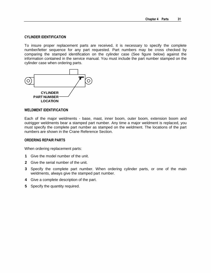
CYLINDER IDENTIFICATION
To insure proper replacement parts are received, it is necessary to specify the complete number/letter sequence for any part requested. Part numbers may be cross checked by comparing the stamped identification on the cylinder case (See figure below) against the information contained in the service manual. You must include the part number stamped on the cylinder case when ordering parts.
CYLINDER
PART NUMBER
LOCATION
WELDMENT IDENTIFICATION
Each of the major weldments - base, mast, inner boom, outer boom, extension boom and outrigger weldments bear a stamped part number. Any time a major weldment is replaced, you must specify the complete part number as stamped on the weldment. The locations of the part numbers are shown in the Crane Reference Section.
ORDERING REPAIR PARTS
When ordering replacement parts:
1 Give the model number of the unit.
2 Give the serial number of the unit.
3 Specify the complete part number. When ordering cylinder parts, or one of the main weldments, always give the stamped part number.
4 Give a complete description of the part.
5 Specify the quantity required.

32 IMT 6006i Technical Specifications & Parts Manual #99904532
Electric Crane Power Safety
Your electric crane runs using power from the vehicle battery. Before beginning major maintenance or repairs, disconnect the power to the crane.
DANGER
POWER SWITCH
TURNED TOOFF
POSITION.
AVOID DEATH OR SERIOUS INJURY!
Before beginning any work on crane,
▪ Turn OFF crane power supply in crane cabinet.
▪ Remove crane power disconnect cable from vehicle battery.
1 Make sure the power switch located inside the crane cabinet is turned to the OFF position.
2 Make sure the crane power disconnect cable is disconnected from the vehicle battery.
Chapter 4 Parts 33
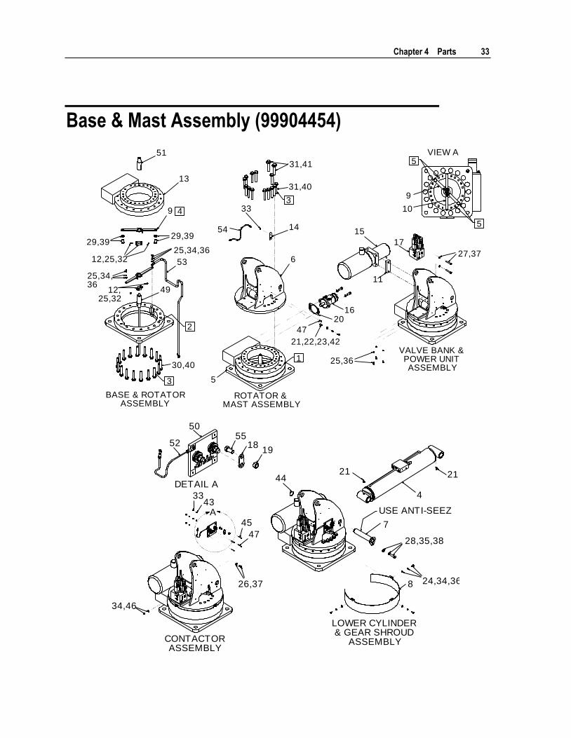
Base & Mast Assembly (99904454)
51
13
9
14
33
54
6
1620
47
9
10
15
17
5
11
53
49
VIEW A
5
5
3
4
2
3
1VALVE BANK &POWER UNITASSEMBLY
ROTATOR &MAST ASSEMBLY
27,37
25,36
21,22,23,42
31,41
31,40
29,39
25,34,3629,39
12,25,32
25,34,36
12,25,32
30,40
BASE & ROTATORASSEMBLY
A
21
4
2144
7
8
50
5255
1918
3343
45
47
LOWER CYLINDER& GEAR SHROUD
ASSEMBLYCONTACTORASSEMBLY
28,35,38
24,34,36
USE ANTI-SEEZ
26,37
34,46
DETAIL A

34 IMT 6006i Technical Specifications & Parts Manual #99904532
WARNINGAvoid injury! Do NOT connect electrical pow er
to crane until all connections have been
tested. Attach electrical w ires and grounds to
components before connecting to mast.
NOTES (SEE REFERENCE NUMBER IN BOX):
1 APPLY BLACK "MOLUB-ALLOY 882 HEAVY" GEAR GREASE TO TURNTABLE GEAR.
2 APPLY RUST PREVENTATIVE.
3 TORQUE TO 160 FT-LB
4 SEE ELECTRIC ROTATOR BRACKET LOCATION (VIEW A).
5 USE THESE TAPPED HOLES FOR ELECTRICAL BRACKET.
6 USE ANTI-SEIZE.
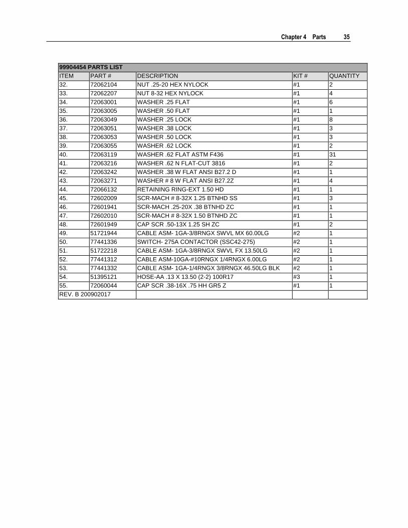
99904454 PARTS LIST
ITEM PART # DESCRIPTION KIT # QUANTITY
1. 51721422 KIT-HRDW BASE & MAST 5005I 1
2. 91722222 KIT- 6006I ELECTRICAL INSTALLATION 1
3. 51721707 KIT-HYD 5005I 1
4. 51721396 CYL- 4.50B X 2.25R X 21.43S 33.45 CC C 1
5. 52721356 WLDMT- BASE 5005I 1
6. 52722162 MAST WELDMENT-5005I/6006I 1
7. 52721425 PIN-TYPE MM 1.50X 8.25 (7.69) 1
8. 60132610 SHROUD- TURNTABLE GEAR 5005I 1
9. 52721420 WLDMT- ELEC ROTATOR BRKT TOP 5005I 1
10. 52721421 WLDMT- ELEC ROTATOR BRKT BOTTOM 5005I 1
11. 60132385 SPACER- POWER UNIT 1
12. 70580194 CLAMP-I" CONDUIT HANGER W/BOLT 2
13. 71056632 GEAR-TRNTBL BRG 17.60" DIA 1
14. 60132856 MNT BRK GREASE HOSE 4004I 1
15. 73511181 POWER UNIT- 2.65CC 24VDC GC 1
16. 73051513 MOTOR-HYD 158-1083-001 1
17. 73734375 VALVE BANK-3 SEC SERIES 3GPM @ 500PSI 24VDC 1
18. 60133635 CONTACT JUNCTION 1
19. 72062002 NUT .38-16 HEX #1 1
20. 76039295 GASKET-GEA19 008-10056-1 1
21. 70034382 CAP-GREASE PRO20 GC-RED #1 3
22. 72053301 COUPLING-BLK .12 #1 1
23. 72053508 ZERK-NPT .12 #1 1
24. 72060001 CAP SCR .25-20X .62 HH GR5 Z #1 3
25. 72060002 CAP SCR .25-20X .75 HH GR5 Z #1 7
26. 72060043 CAP SCR .38-16X .62 HH GR5 Z #1 1
27. 72060051 CAP SCR .38-16X 2.25 HH GR5 Z #1 2
28. 72060095 CAP SCR .50-13X 2.00 HH GR5 Z #1 1
29. 72060147 CAP SCR .62-11X 1.00 HH GR5 Z #1 2
30. 72060173 CAP SCR .62-11X 3.75 HH GR8 Z #1 18
31. 72060178 CAP SCR .62-11X 4.00 HH GR8 Z #1 15
Chapter 4 Parts 35
99904454 PARTS LIST
ITEM PART # DESCRIPTION KIT # QUANTITY
32. 72062104 NUT .25-20 HEX NYLOCK #1 2
33. 72062207 NUT 8-32 HEX NYLOCK #1 4
34. 72063001 WASHER .25 FLAT #1 6
35. 72063005 WASHER .50 FLAT #1 1
36. 72063049 WASHER .25 LOCK #1 8
37. 72063051 WASHER .38 LOCK #1 3
38. 72063053 WASHER .50 LOCK #1 3
39. 72063055 WASHER .62 LOCK #1 2
40. 72063119 WASHER .62 FLAT ASTM F436 #1 31
41. 72063216 WASHER .62 N FLAT-CUT 3816 #1 2
42. 72063242 WASHER .38 W FLAT ANSI B27.2 D #1 1
43. 72063271 WASHER # 8 W FLAT ANSI B27.2Z #1 4
44. 72066132 RETAINING RING-EXT 1.50 HD #1 1
45. 72602009 SCR-MACH # 8-32X 1.25 BTNHD SS #1 3
46. 72601941 SCR-MACH .25-20X .38 BTNHD ZC #1 1
47. 72602010 SCR-MACH # 8-32X 1.50 BTNHD ZC #1 1
48. 72601949 CAP SCR .50-13X 1.25 SH ZC #1 2
49. 51721944 CABLE ASM- 1GA-3/8RNGX SWVL MX 60.00LG #2 1
50. 77441336 SWITCH- 275A CONTACTOR (SSC42-275) #2 1
51. 51722218 CABLE ASM- 1GA-3/8RNGX SWVL FX 13.50LG #2 1
52. 77441312 CABLE ASM-10GA-#10RNGX 1/4RNGX 6.00LG #2 1
53. 77441332 CABLE ASM- 1GA-1/4RNGX 3/8RNGX 46.50LG BLK #2 1
54. 51395121 HOSE-AA .13 X 13.50 (2-2) 100R17 #3 1
55. 72060044 CAP SCR .38-16X .75 HH GR5 Z #1 1
REV. B 200902017
36 IMT 6006i Technical Specifications & Parts Manual #99904532
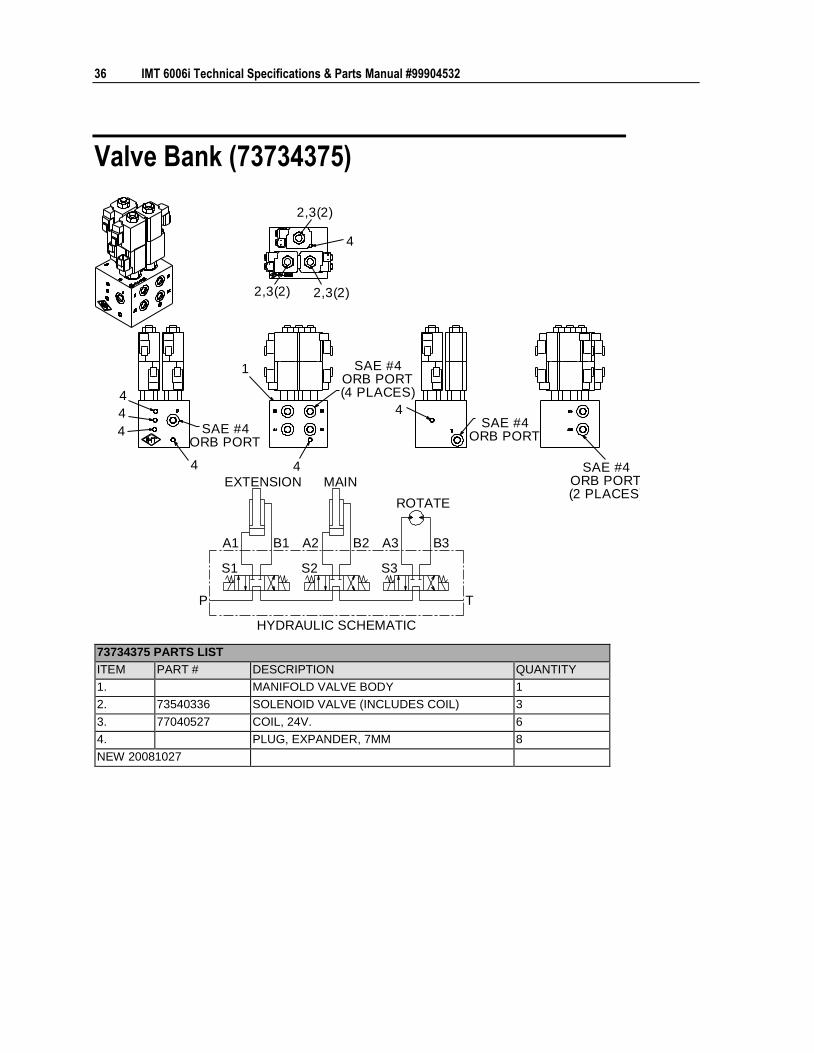
Valve Bank (73734375)
1
4 4
4
4
4
4
4
SAE #4ORB PORT(2 PLACES)
SAE #4ORB PORT
SAE #4ORB PORT(4 PLACES)
SAE #4ORB PORT
2,3(2) 2,3(2)
2,3(2)
B2A2 B3A3B1A1
S2 S3S1
P T
EXTENSION MAIN
ROTATE
HYDRAULIC SCHEMATIC
73734375 PARTS LIST
ITEM PART # DESCRIPTION QUANTITY
1. MANIFOLD VALVE BODY 1
2. 73540336 SOLENOID VALVE (INCLUDES COIL) 3
3. 77040527 COIL, 24V. 6
4. PLUG, EXPANDER, 7MM 8
NEW 20081027
Chapter 4 Parts 37
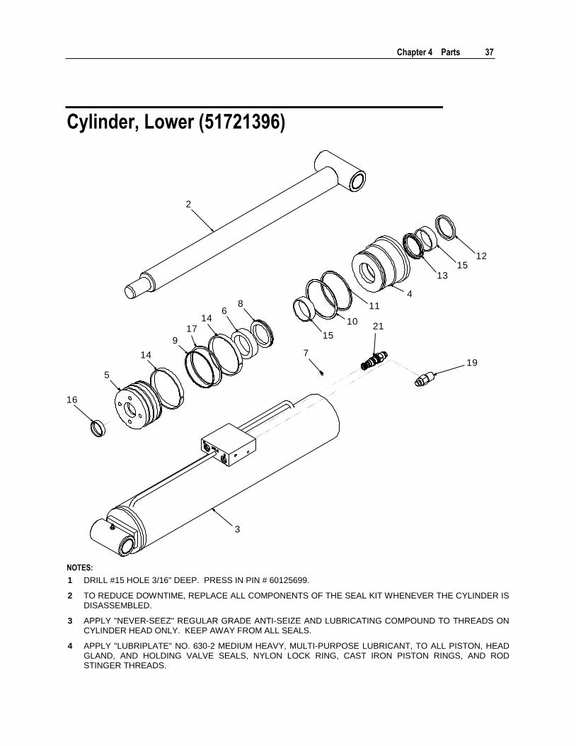
Cylinder, Lower (51721396)
2
7
3
16
5
14
9
146
8
15
11
1315
12
19
4
1017 21
NOTES:
1 DRILL #15 HOLE 3/16" DEEP. PRESS IN PIN # 60125699.
2 TO REDUCE DOWNTIME, REPLACE ALL COMPONENTS OF THE SEAL KIT WHENEVER THE CYLINDER IS DISASSEMBLED.
3 APPLY "NEVER-SEEZ" REGULAR GRADE ANTI-SEIZE AND LUBRICATING COMPOUND TO THREADS ON CYLINDER HEAD ONLY. KEEP AWAY FROM ALL SEALS.
4 APPLY "LUBRIPLATE" NO. 630-2 MEDIUM HEAVY, MULTI-PURPOSE LUBRICANT, TO ALL PISTON, HEAD GLAND, AND HOLDING VALVE SEALS, NYLON LOCK RING, CAST IRON PISTON RINGS, AND ROD STINGER THREADS.
38 IMT 6006i Technical Specifications & Parts Manual #99904532
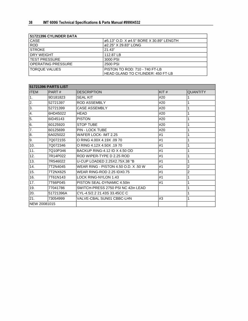
51721396 CYLINDER DATA
CASE ø5.13" O.D. X ø4.5" BORE X 30.89" LENGTH
ROD ø2.25" X 29.83" LONG
STROKE 21.43"
DRY WEIGHT 112.87 LB
TEST PRESSURE 3000 PSI
OPERATING PRESSURE 2500 PSI
TORQUE VALUES PISTON TO ROD: 710 - 740 FT-LB HEAD GLAND TO CYLINDER: 450 FT-LB
51721396 PARTS LIST
ITEM PART # DESCRIPTION KIT # QUANTITY
1. 9D181823 SEAL KIT #20 1
2. 52721397 ROD ASSEMBLY #20 1
3. 52721399 CASE ASSEMBLY #20 1
4. 6HD45022 HEAD #20 1
5. 6ID45143 PISTON #20 1
6. 60125920 STOP TUBE #20 1
7. 60125699 PIN - LOCK TUBE #20 1
8. 6A025022 WAFER LOCK- IMT 2.25 #1 1
9. 7Q072155 O RING 4.00X 4.19X .09 70 #1 1
10. 7Q072346 O RING 4.12X 4.50X .19 70 #1 1
11. 7Q10P346 BACKUP RING-4.12 ID X 4.50 OD #1 1
12. 7R14P022 ROD WIPER-TYPE D 2.25 ROD #1 1
13. 7R546022 U-CUP LOADED 2.25X2.75X.38 "B #1 1
14. 7T2N4045 WEAR RING - PISTON 4.50 O.D. X .50 W #1 2
15. 7T2NX625 WEAR RING-ROD 2.25 IDX0.75 #1 2
16. 7T61N143 LOCK RING-NYLON 1.43 #1 1
17. 7T66P045 PISTON SEAL-DYNAMIC 4.50in #1 1
19. 77041786 SWITCH-PRESS 2750 PSI NC 42in LEAD 1
20. 51721396A CYL-4.5/2.2 21.43S 33.45CC C 1
21. 73054999 VALVE-CBAL SUN01 CBBC-LHN #3 1
NEW 20081015
Chapter 4 Parts 39
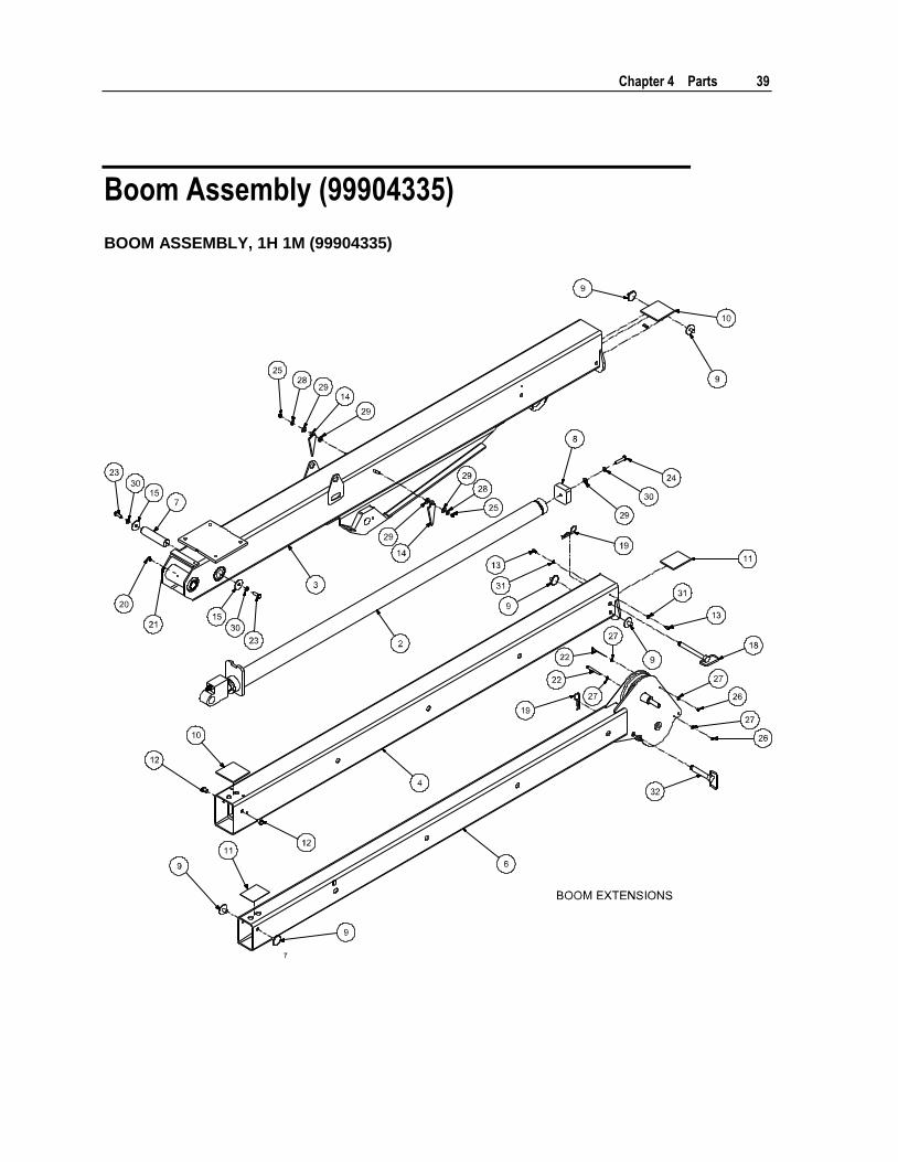
Boom Assembly (99904335)
BOOM ASSEMBLY, 1H 1M (99904335)
40 IMT 6006i Technical Specifications & Parts Manual #99904532
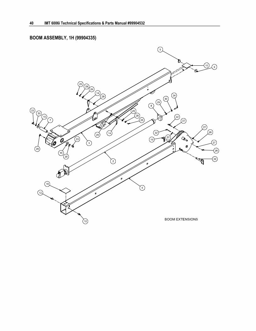
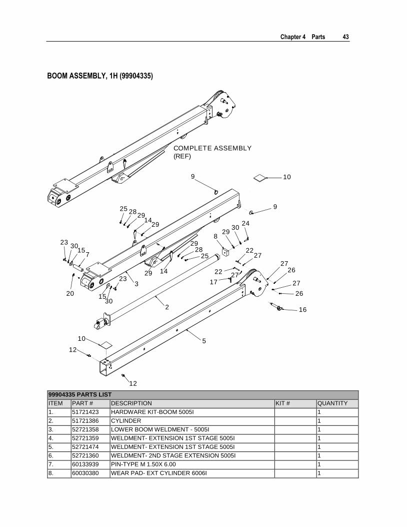
BOOM ASSEMBLY, 1H (99904335)

Chapter 4 Parts 41
99904335 Complete Parts List Item No. Part No. Description Kit No. Qty.
1. 51721423 KIT-HRDW BOOM 5005I
1
2. 51721386 CYL-2.5/1.5 72.00S 7.37CC C
1
3. 52725221 LOWER BOOM WLDMNT - 5005I-6006I
1
4. 52721359 WLDMT- EXTENSION 1ST STAGE 5005I
1
5. 52721474 WLDMT- EXTENSION 1ST STAGE 5005I
1
6. 52721360 WLDMT- 2ND STAGE EXTENSION 5005I
1
7. 60133939 PIN-TYPE M 1.50X 6.00
1
8. 60030380 WEAR PAD- EXT CYLINDER 6006I
1
9. 60030339 WEAR PAD-RND 0.19X 2.00X .60X .81
6
10. 60030340 WEAR PAD-RC 0.19X 4.50X 4.50
2
11. 60030341 WEAR PAD-RC 0.19X 4.50X 3.50
2
12. 60133062 WEAR PAD-RND 0.19X 1.00X .62X .81 STL
2
13. 60132302 STOP SCREW 3/8-24 X .50
2
14. 60105544 PLATE-ANGLE PLASTIC
2
15. 72063273 WASHER .52ID X 2.00OD X 10GA
2
18. 70144211 PIN- .75X 6.50LG WORKSAVER
1
19. 72066145 HAIR PIN .19 DIA .63-1.00 SHAFT (PART OF 70144211) REF 2
20. 70034382 CAP-GREASE PRO20 GC-RED 1 1
21. 72053507 ZERK-STR THD .25-28 1 1
22. 72060013 CAP SCR .25-20X 3.25 HH GR5 Z 1 2
23. 72060092 CAP SCR .50-13X 1.25 HH GR5 Z 1 2
24. 72060928 CAP SCR .50-13X 2.25 HH GR5 Z 1 1
25. 72062103 NUT .38-16 HEX NYLOCK 1 2
26. 72062104 NUT .25-20 HEX NYLOCK 1 2
27. 72063001 WASHER .25 FLAT 1 4
28. 72063003 WASHER .38 FLAT 1 2
29. 72063005 WASHER .50 FLAT 1 5
30. 72063053 WASHER .50 LOCK 1 3
31. 72063051 WASHER .38 LOCK 1 2
32. 70144209 PIN- .75X 4.50 LG WS80-WS100
1
REV. E 20180227
42 IMT 6006i Technical Specifications & Parts Manual #99904532
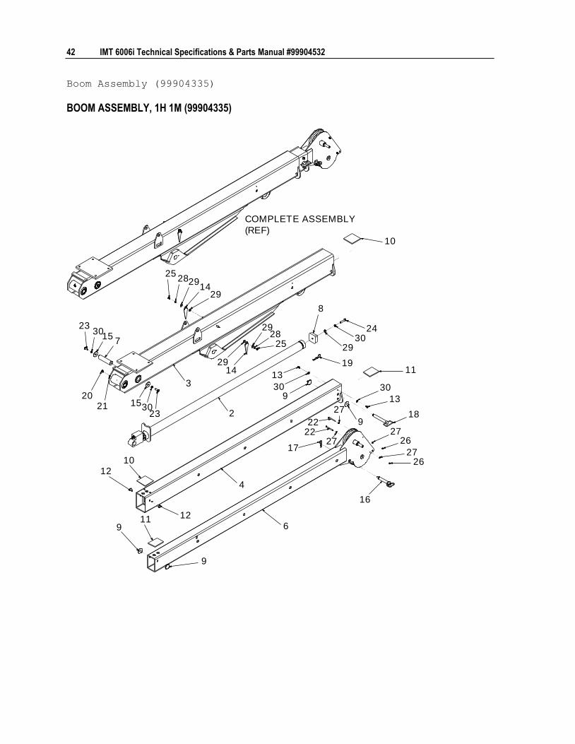
Boom Assembly (99904335)
BOOM ASSEMBLY, 1H 1M (99904335)
2021
2
2914
292825
2528
29
1429
2430
29
8
13
309
1911
30
13
189
17
2726
16
2627
4
6
1012
12119
9
3
10
2227
22
27
715
3023
153023
COMPLETE ASSEMBLY
(REF)
Chapter 4 Parts 43
BOOM ASSEMBLY, 1H (99904335)
20
2
10
9
9
1429
292825
2528
29
1429
2430
298
17
2227
2227
2726
27
26
16
12
10
12
5
3
715
3023
1530
23
COMPLETE ASSEMBLY
(REF)
99904335 PARTS LIST
ITEM PART # DESCRIPTION KIT # QUANTITY
1. 51721423 HARDWARE KIT-BOOM 5005I 1
2. 51721386 CYLINDER 1
3. 52721358 LOWER BOOM WELDMENT - 5005I 1
4. 52721359 WELDMENT- EXTENSION 1ST STAGE 5005I 1
5. 52721474 WELDMENT- EXTENSION 1ST STAGE 5005I 1
6. 52721360 WELDMENT- 2ND STAGE EXTENSION 5005I 1
7. 60133939 PIN-TYPE M 1.50X 6.00 1
8. 60030380 WEAR PAD- EXT CYLINDER 6006I 1
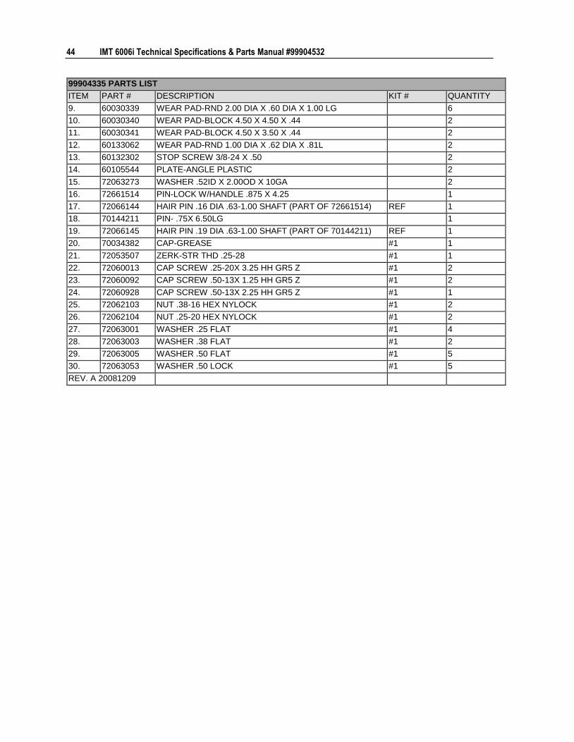
44 IMT 6006i Technical Specifications & Parts Manual #99904532
99904335 PARTS LIST
ITEM PART # DESCRIPTION KIT # QUANTITY
9. 60030339 WEAR PAD-RND 2.00 DIA X .60 DIA X 1.00 LG 6
10. 60030340 WEAR PAD-BLOCK 4.50 X 4.50 X .44 2
11. 60030341 WEAR PAD-BLOCK 4.50 X 3.50 X .44 2
12. 60133062 WEAR PAD-RND 1.00 DIA X .62 DIA X .81L 2
13. 60132302 STOP SCREW 3/8-24 X .50 2
14. 60105544 PLATE-ANGLE PLASTIC 2
15. 72063273 WASHER .52ID X 2.00OD X 10GA 2
16. 72661514 PIN-LOCK W/HANDLE .875 X 4.25 1
17. 72066144 HAIR PIN .16 DIA .63-1.00 SHAFT (PART OF 72661514) REF 1
18. 70144211 PIN- .75X 6.50LG 1
19. 72066145 HAIR PIN .19 DIA .63-1.00 SHAFT (PART OF 70144211) REF 1
20. 70034382 CAP-GREASE #1 1
21. 72053507 ZERK-STR THD .25-28 #1 1
22. 72060013 CAP SCREW .25-20X 3.25 HH GR5 Z #1 2
23. 72060092 CAP SCREW .50-13X 1.25 HH GR5 Z #1 2
24. 72060928 CAP SCREW .50-13X 2.25 HH GR5 Z #1 1
25. 72062103 NUT .38-16 HEX NYLOCK #1 2
26. 72062104 NUT .25-20 HEX NYLOCK #1 2
27. 72063001 WASHER .25 FLAT #1 4
28. 72063003 WASHER .38 FLAT #1 2
29. 72063005 WASHER .50 FLAT #1 5
30. 72063053 WASHER .50 LOCK #1 5
REV. A 20081209

Chapter 4 Parts 45
Light Kit (99906235)
2
5
4
4
6
5
2
5
5
3
ITEM NO. PART NO. DESCRIPTION KIT NO. QTY. 1. 51727280 ELECT KIT-BOOM FLOOD LIGHTS 5005i-6006i 1
2. 77040581 FLOODLIGHT-LED 12-36VDC 1 2
3. 60145056 BRACKET-LIGHT 5005i-6006i 1 1
4. 60145332 SLEEVE-TYPE C .44X .75X .25 1 2
5. 72063002 WASHER .31 FLAT 1 4
6. 72060076 CAP SCR .44-14X 6.00 HH GR5 Z 1 1
REV. B
Effective 1-1-2018
46
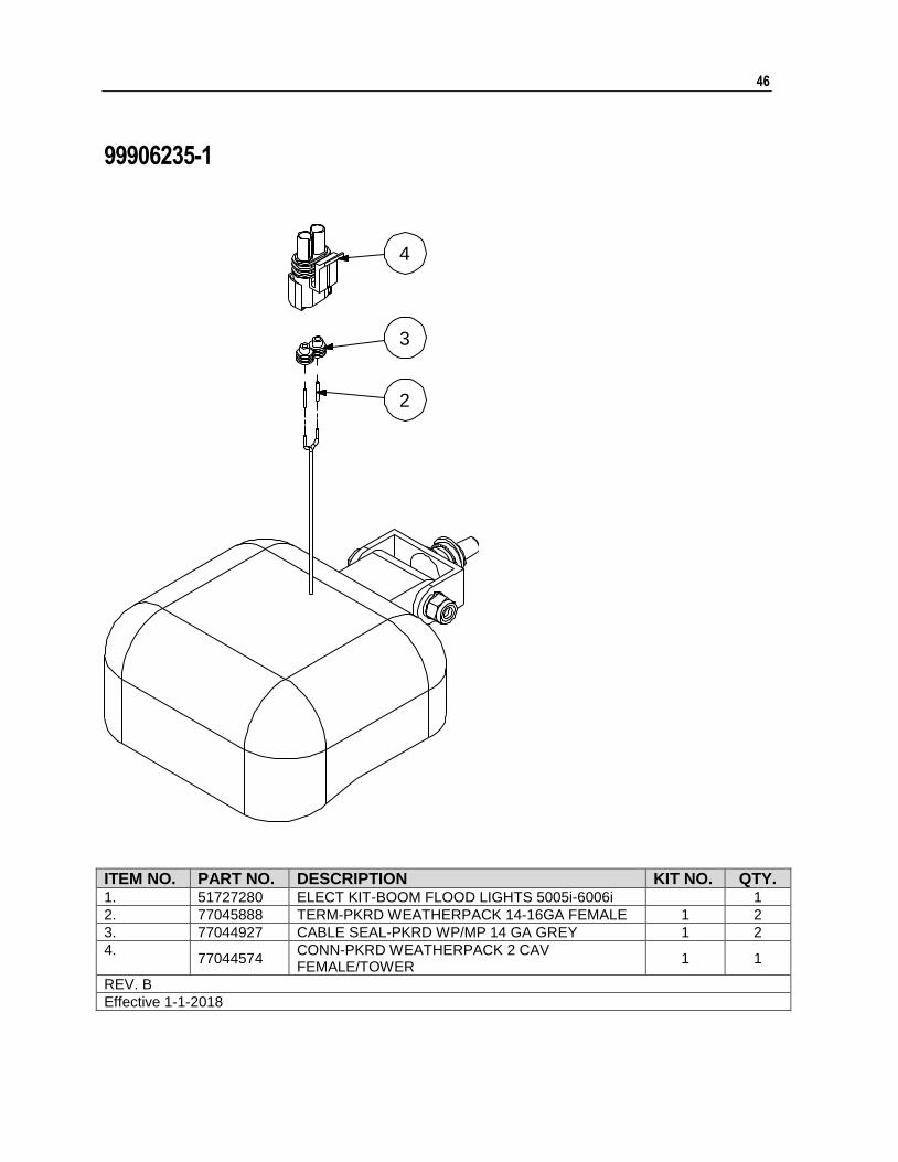
99906235-1
2
3
4
ITEM NO. PART NO. DESCRIPTION KIT NO. QTY. 1. 51727280 ELECT KIT-BOOM FLOOD LIGHTS 5005i-6006i 1
2. 77045888 TERM-PKRD WEATHERPACK 14-16GA FEMALE 1 2
3. 77044927 CABLE SEAL-PKRD WP/MP 14 GA GREY 1 2
4. 77044574
CONN-PKRD WEATHERPACK 2 CAV FEMALE/TOWER
1 1
REV. B
Effective 1-1-2018
47
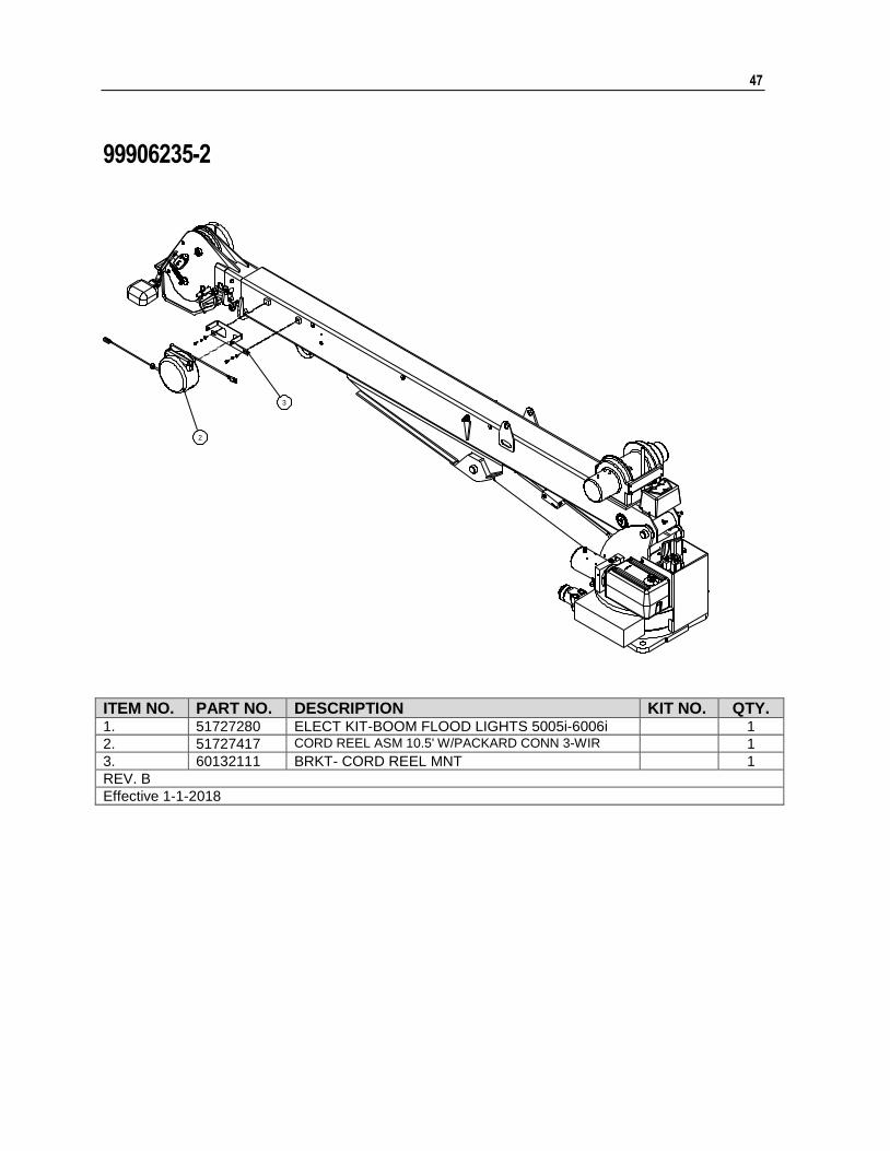
99906235-2
2
3
ITEM NO. PART NO. DESCRIPTION KIT NO. QTY. 1. 51727280 ELECT KIT-BOOM FLOOD LIGHTS 5005i-6006i 1
2. 51727417 CORD REEL ASM 10.5' W/PACKARD CONN 3-WIR 1
3. 60132111 BRKT- CORD REEL MNT 1
REV. B
Effective 1-1-2018
48
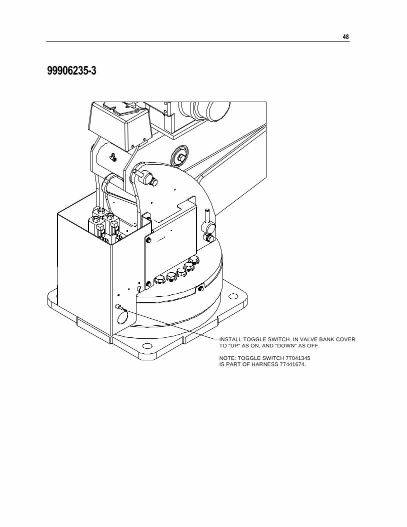
99906235-3
INSTALL TOGGLE SWITCH IN VALVE BANK COVER
TO "UP" AS ON, AND "DOWN" AS OFF.
NOTE: TOGGLE SWITCH 77041345IS PART OF HARNESS 77441674.

49
Cylinder, Extension (51721386)
2
8
9
1417
4
1517
13
12
10
5
1116
618
16
7
3
NOTES:
1 DRILL #15 HOLE 3/16" DEEP. PRESS IN PIN # 60125699.
2 TO REDUCE DOWNTIME, REPLACE ALL COMPONENTS OF THE SEAL KIT WHENEVER THE CYLINDER IS DISASSEMBLED.
3 APPLY "NEVER-SEEZ" REGULAR GRADE ANTI-SEIZE AND LUBRICATING COMPOUND TO THREADS ON CYLINDER HEAD ONLY. KEEP AWAY FROM ALL SEALS.
4 APPLY "LUBRIPLATE" NO. 630-2 MEDIUM HEAVY, MULTI-PURPOSE LUBRICANT, TO ALL PISTON, HEAD GLAND, AND HOLDING VALVE SEALS, NYLON LOCK RING, CAST IRON PISTON RINGS, AND ROD STINGER THREADS.
51721386 CYLINDER DATA
CASE ø3" O.D. X ø2.5" BORE X 81.26" LENGTH
ROD ø1.5" X 82.69" LONG
STROKE 72"
DRY WEIGHT 84.65 LB
TORQUES HEAD: 250 FT-LB PISTON: 500-530 FT-LB
TEST PRESSURE 3000 PSI
OPERATING PRESSURE 2500 PSI
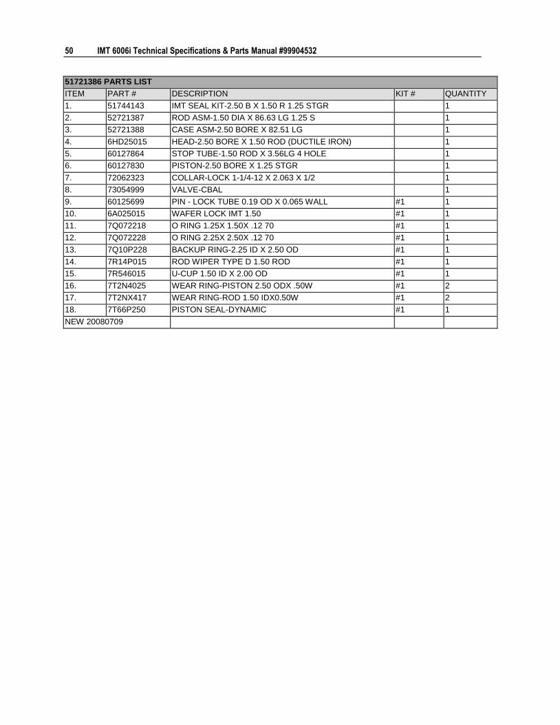
50 IMT 6006i Technical Specifications & Parts Manual #99904532
51721386 PARTS LIST
ITEM PART # DESCRIPTION KIT # QUANTITY
1. 51744143 IMT SEAL KIT-2.50 B X 1.50 R 1.25 STGR 1
2. 52721387 ROD ASM-1.50 DIA X 86.63 LG 1.25 S 1
3. 52721388 CASE ASM-2.50 BORE X 82.51 LG 1
4. 6HD25015 HEAD-2.50 BORE X 1.50 ROD (DUCTILE IRON) 1
5. 60127864 STOP TUBE-1.50 ROD X 3.56LG 4 HOLE 1
6. 60127830 PISTON-2.50 BORE X 1.25 STGR 1
7. 72062323 COLLAR-LOCK 1-1/4-12 X 2.063 X 1/2 1
8. 73054999 VALVE-CBAL 1
9. 60125699 PIN - LOCK TUBE 0.19 OD X 0.065 WALL #1 1
10. 6A025015 WAFER LOCK IMT 1.50 #1 1
11. 7Q072218 O RING 1.25X 1.50X .12 70 #1 1
12. 7Q072228 O RING 2.25X 2.50X .12 70 #1 1
13. 7Q10P228 BACKUP RING-2.25 ID X 2.50 OD #1 1
14. 7R14P015 ROD WIPER TYPE D 1.50 ROD #1 1
15. 7R546015 U-CUP 1.50 ID X 2.00 OD #1 1
16. 7T2N4025 WEAR RING-PISTON 2.50 ODX .50W #1 2
17. 7T2NX417 WEAR RING-ROD 1.50 IDX0.50W #1 2
18. 7T66P250 PISTON SEAL-DYNAMIC #1 1
NEW 20080709
Chapter 4 Parts 51
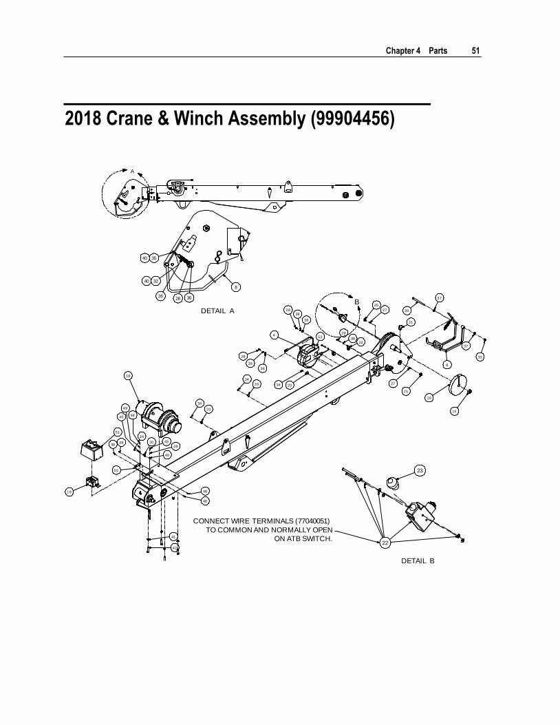
2018 Crane & Winch Assembly (99904456)
A
3540
3240
26
22
23
34
20
34
20
34
20 34 20
28
38
28
25
21
10
25
30
37
37
33
15
27
27
18
41
42
1238
29
36
36
38
51
19
3628
8
8
4848
48
49
40
48
49
40
53
48
48
524
CONNECT WIRE TERMINALS (77040051)
TO COMMON AND NORMALLY OPEN
ON ATB SWITCH.
DETAIL B
B
DETAIL A
52 IMT 6006i Technical Specifications & Parts Manual #99904532
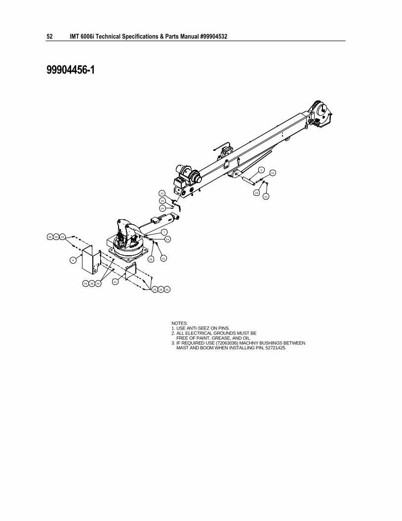
99904456-1
NOTES:1. USE ANTI-SEEZ ON PINS.2. ALL ELECTRICAL GROUNDS MUST BE
FREE OF PAINT, GREASE, AND OIL.3. IF REQUIRED USE (72063036) MACHNY BUSHINGS BETWEEN
MAST AND BOOM WHEN INSTALLING PIN, 52721425.
39 31
39
31
44
36
24
9
11
28 38 36
283836
283836
546
7
54
Chapter 4 Parts 53
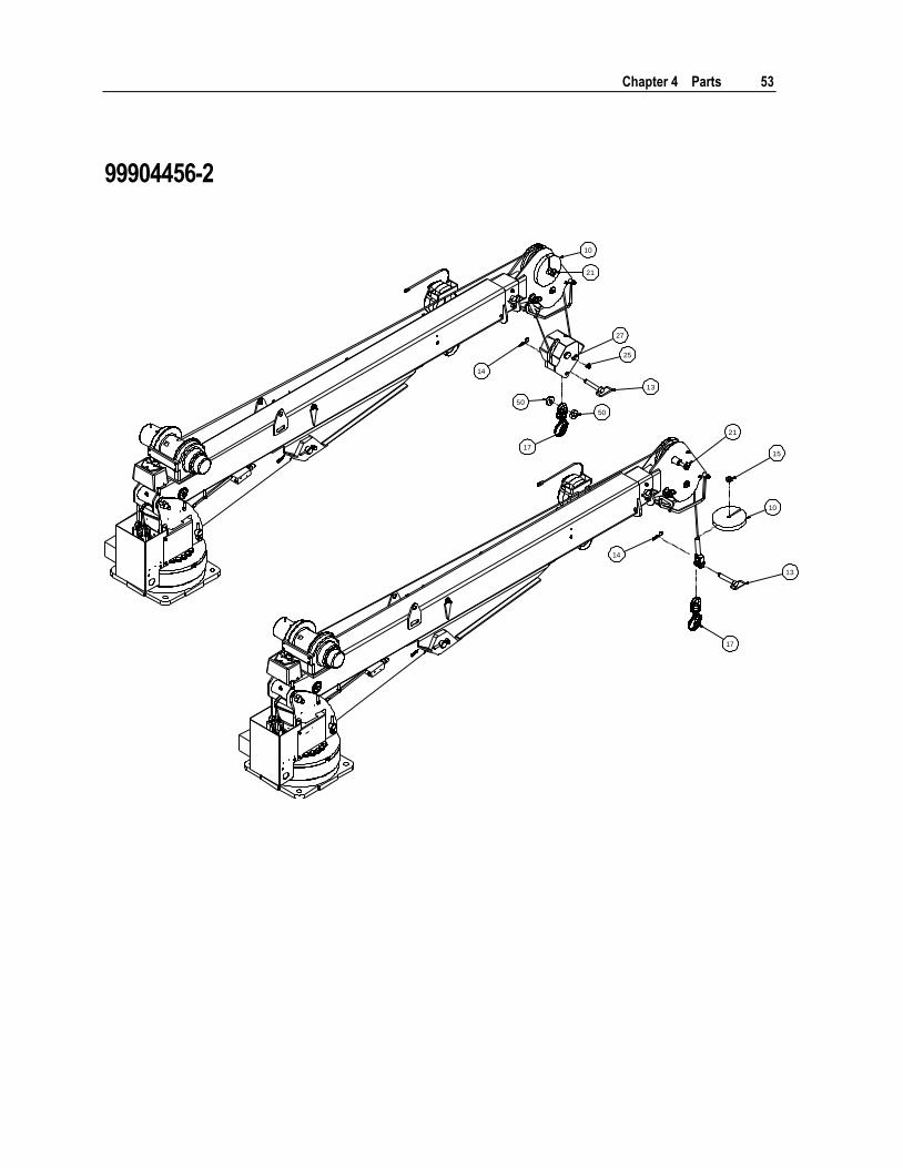
99904456-2
10
15
10
21
25
14
14
21
27
13
13
50
50
17
17
54
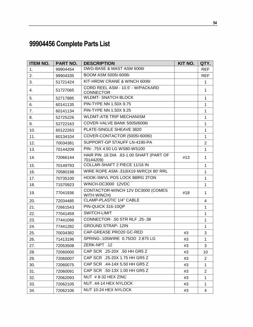
99904456 Complete Parts List
ITEM NO. PART NO. DESCRIPTION KIT NO. QTY.
1. 99904454 DWG-BASE & MAST ASM 6006I
REF
2. 99904335 BOOM ASM 5005I-6006i
REF
3. 51721424 KIT-HRDW CRANE & WINCH 6006I
1
4. 51727065 CORD REEL ASM - 10.5' - W/PACKARD CONNECTOR
1
5. 52717885 WLDMT- SNATCH BLOCK
1
6. 60141135 PIN-TYPE NN 1.50X 9.75
1
7. 60141134 PIN-TYPE NN 1.50X 9.25
1
8. 52725226 WLDMT-ATB TRIP MECHANISM
1
9. 52722163 COVER-VALVE BANK 5005i/6006i
1
10. 60122263 PLATE-SINGLE SHEAVE 3820
1
11. 60134104 COVER-CONTACTOR (5005I-6006I)
1
12. 70034381 SUPPORT-GP STAUFF LN-4190-PA
2
13. 70144209 PIN- .75X 4.50 LG WS80-WS100
1
14. 72066144 HAIR PIN .16 DIA .63-1.00 SHAFT (PART OF 70144209)
#13 1
15. 70149793 COLLAR-SHAFT 2 PIECE 11/16 IN
1
16. 70580198 WIRE ROPE ASM-.31(6X19 IWRC)X 80' RRL
1
17. 70735100 HOOK-SWVL POS LOCK BBRG 3TON
1
18. 71570923 WINCH-DC3000 12VDC
1
19. 77041936 CONTACTOR-WINCH 12V DC3000 (COMES WITH WINCH)
#18 1
20. 72034485 CLAMP-PLASTIC 1/4" CABLE
4
21. 72661543 PIN-QUICK 316-10QP
1
22. 77041459 SWITCH-LIMIT
1
23. 77441096 CONNECTOR- .50 STR RLF .25-.38
1
24. 77441282 GROUND STRAP- 12IN
1
25. 70034382 CAP-GREASE PRO20 GC-RED #3 3
26. 71413196 SPRING-.105WIRE 0.75OD 2.875 LG #3 1
27. 72053508 ZERK-NPT .12 #3 3
28. 72060000 CAP SCR .25-20X .50 HH GR5 Z #3 10
29. 72060007 CAP SCR .25-20X 1.75 HH GR5 Z #3 2
30. 72060075 CAP SCR .44-14X 5.50 HH GR5 Z #3 1
31. 72060091 CAP SCR .50-13X 1.00 HH GR5 Z #3 2
32. 72062093 NUT # 8-32 HEX ZINC #3 1
33. 72062105 NUT .44-14 HEX NYLOCK #3 1
34. 72062106 NUT 10-24 HEX NYLOCK #3 4
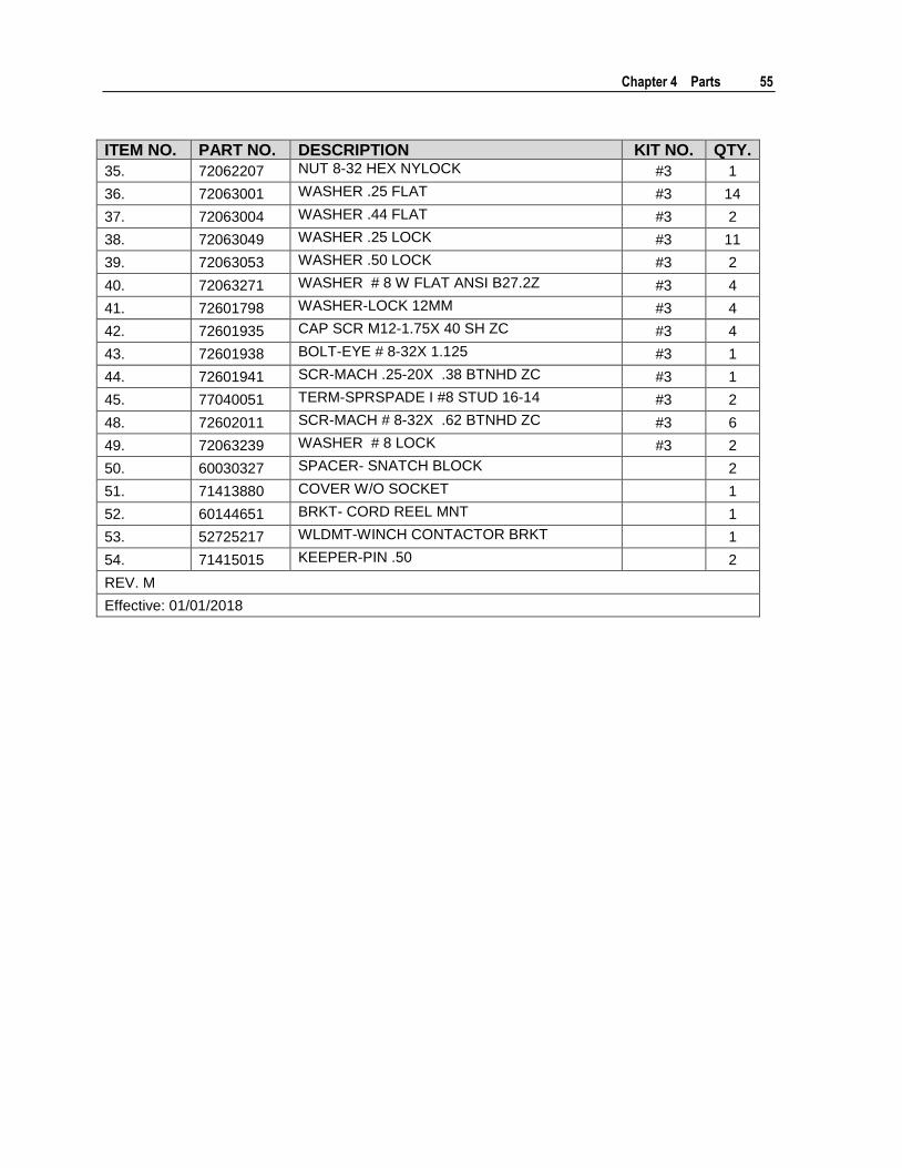
Chapter 4 Parts 55
ITEM NO. PART NO. DESCRIPTION KIT NO. QTY.
35. 72062207 NUT 8-32 HEX NYLOCK #3 1
36. 72063001 WASHER .25 FLAT #3 14
37. 72063004 WASHER .44 FLAT #3 2
38. 72063049 WASHER .25 LOCK #3 11
39. 72063053 WASHER .50 LOCK #3 2
40. 72063271 WASHER # 8 W FLAT ANSI B27.2Z #3 4
41. 72601798 WASHER-LOCK 12MM #3 4
42. 72601935 CAP SCR M12-1.75X 40 SH ZC #3 4
43. 72601938 BOLT-EYE # 8-32X 1.125 #3 1
44. 72601941 SCR-MACH .25-20X .38 BTNHD ZC #3 1
45. 77040051 TERM-SPRSPADE I #8 STUD 16-14 #3 2
48. 72602011 SCR-MACH # 8-32X .62 BTNHD ZC #3 6
49. 72063239 WASHER # 8 LOCK #3 2
50. 60030327 SPACER- SNATCH BLOCK
2
51. 71413880 COVER W/O SOCKET
1
52. 60144651 BRKT- CORD REEL MNT
1
53. 52725217 WLDMT-WINCH CONTACTOR BRKT
1
54. 71415015 KEEPER-PIN .50
2
REV. M
Effective: 01/01/2018
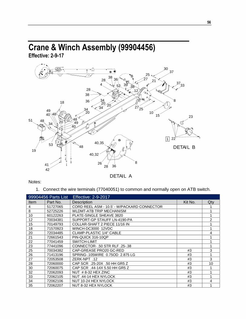
56
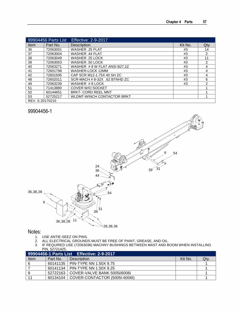
Crane & Winch Assembly (99904456) Effective: 2-9-17
1
2725
1015
33
8
3721
3730
27
25
22
23
83628
26
40,32
40,3548
19
53
18
48
48
49
4934
40
40
51 48
3434
20
20
2020
34
38
28
36
4
1238
3952
3828 36
41
42
B
DETAIL A
DETAIL B
Notes:
1. Connect the wire terminals (77040051) to common and normally open on ATB switch.
99904456 Parts List Effective: 2-9-2017 Item Part No. Description Kit No. Qty 4 51727065 CORD REEL ASM - 10.5' - W/PACKARD CONNECTOR 1
8 52725226 WLDMT-ATB TRIP MECHANISM 1
10 60122263 PLATE-SINGLE SHEAVE 3820 1
12 70034381 SUPPORT-GP STAUFF LN-4190-PA 2
15 70149793 COLLAR-SHAFT 2 PIECE 11/16 IN 1
18 71570923 WINCH-DC3000 12VDC 1
20 72034485 CLAMP-PLASTIC 1/4" CABLE 4
21 72661543 PIN-QUICK 316-10QP 1
22 77041459 SWITCH-LIMIT 1
23 77441096 CONNECTOR- .50 STR RLF .25-.38 1
25 70034382 CAP-GREASE PRO20 GC-RED #3 3
26 71413196 SPRING-.105WIRE 0.75OD 2.875 LG #3 1
27 72053508 ZERK-NPT .12 #3 3
28 72060000 CAP SCR .25-20X .50 HH GR5 Z #3 10
30 72060075 CAP SCR .44-14X 5.50 HH GR5 Z #3 1
32 72062093 NUT # 8-32 HEX ZINC #3 1
33 72062105 NUT .44-14 HEX NYLOCK #3 1
34 72062106 NUT 10-24 HEX NYLOCK #3 4
35 72062207 NUT 8-32 HEX NYLOCK #3 1
Chapter 4 Parts 57
99904456 Parts List Effective: 2-9-2017 Item Part No. Description Kit No. Qty 36 72063001 WASHER .25 FLAT #3 14
37 72063004 WASHER .44 FLAT #3 2
38 72063049 WASHER .25 LOCK #3 11
39 72063053 WASHER .50 LOCK #3 2
40 72063271 WASHER # 8 W FLAT ANSI B27.2Z #3 4
41 72601798 WASHER-LOCK 12MM #3 4
42 72601935 CAP SCR M12-1.75X 40 SH ZC #3 4
48 72602011 SCR-MACH # 8-32X .62 BTNHD ZC #3 6
49 72063239 WASHER # 8 LOCK #3 2
51 71413880 COVER W/O SOCKET 1
52 60144651 BRKT- CORD REEL MNT 1
53 52725217 WLDMT-WINCH CONTACTOR BRKT 1
REV. S 20170215
99904456-1
28,38,36
1136,38,28
9
36,38,28
3931
54
3139
546
7
44
36
24
Notes: 1. USE ANTIE-SEEZ ON PINS. 2. ALL ELECTRICAL GROUNDS MUST BE FREE OF PAINT, GREASE, AND OIL. 3. IF REQUIRED USE (72063036) MACHNY BUSHINGS BETWEEN MAST AND BOOM WHEN INSTALLING
PIN, 52721425.
99904456-1 Parts List Effective: 2-9-2017 Item Part No. Description Kit No. Qty.
6 60141135 PIN-TYPE NN 1.50X 9.75 1
7 60141134 PIN-TYPE NN 1.50X 9.25 1
9 52722163 COVER-VALVE BANK 5005i/6006i 1
11 60134104 COVER-CONTACTOR (5005I-6006I) 1

58 IMT 6006i Technical Specifications & Parts Manual #99904532
99904456-1 Parts List Effective: 2-9-2017 Item Part No. Description Kit No. Qty.
24 77441282 GROUND STRAP- 12IN 1
28 72060000 CAP SCR .25-20X .50 HH GR5 Z #3 10
31 72060091 CAP SCR .50-13X 1.00 HH GR5 Z #3 2
36 72063001 WASHER .25 FLAT #3 14
38 72063049 WASHER .25 LOCK #3 11
39 72063053 WASHER .50 LOCK #3 2
44 72601941 SCR-MACH .25-20X .38 BTNHD ZC #3 1
54 71415015 KEEPER-PIN .50 2
REV. S 20170215
99904456-2 1021
2725
13
14
5017
5021
15
10
13
17
14
99904456-2 Parts List Effective: 2-9-2017 Item Part No. Description Kit No. Qty
10 60122263 PLATE-SINGLE SHEAVE 3820 1
13 70144209 PIN- .75X 4.50 LG WS80-WS100 1
14 72066144 HAIR PIN .16 DIA .63-1.00 SHAFT (PART OF 70144209) #13 1
15 70149793 COLLAR-SHAFT 2 PIECE 11/16 IN 1
17 71073920 HOOK-SWVL L-322A-3T W/LATCH 1
21 72661543 PIN-QUICK 316-10QP 1
25 70034382 CAP-GREASE PRO20 GC-RED #3 3
27 72053508 ZERK-NPT .12 #3 3

Chapter 4 Parts 59
99904456-2 Parts List Effective: 2-9-2017 Item Part No. Description Kit No. Qty
50 60030327 SPACER- SNATCH BLOCK 2
Rev S 20170215
60 IMT 6006i Technical Specifications & Parts Manual #99904532
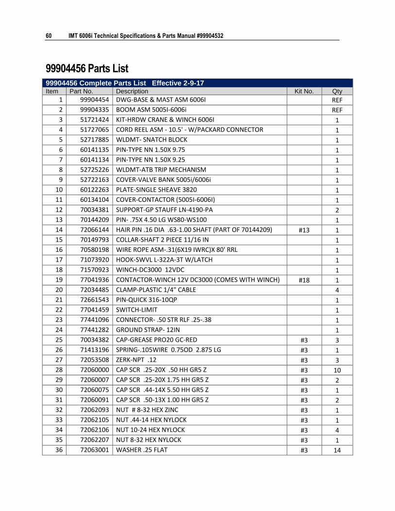
99904456 Parts List 99904456 Complete Parts List Effective 2-9-17 Item Part No. Description Kit No. Qty
1 99904454 DWG-BASE & MAST ASM 6006I
REF
2 99904335 BOOM ASM 5005I-6006i
REF
3 51721424 KIT-HRDW CRANE & WINCH 6006I
1
4 51727065 CORD REEL ASM - 10.5' - W/PACKARD CONNECTOR
1
5 52717885 WLDMT- SNATCH BLOCK
1
6 60141135 PIN-TYPE NN 1.50X 9.75
1
7 60141134 PIN-TYPE NN 1.50X 9.25
1
8 52725226 WLDMT-ATB TRIP MECHANISM
1
9 52722163 COVER-VALVE BANK 5005i/6006i
1
10 60122263 PLATE-SINGLE SHEAVE 3820
1
11 60134104 COVER-CONTACTOR (5005I-6006I)
1
12 70034381 SUPPORT-GP STAUFF LN-4190-PA
2
13 70144209 PIN- .75X 4.50 LG WS80-WS100
1
14 72066144 HAIR PIN .16 DIA .63-1.00 SHAFT (PART OF 70144209) #13 1
15 70149793 COLLAR-SHAFT 2 PIECE 11/16 IN
1
16 70580198 WIRE ROPE ASM-.31(6X19 IWRC)X 80' RRL
1
17 71073920 HOOK-SWVL L-322A-3T W/LATCH
1
18 71570923 WINCH-DC3000 12VDC
1
19 77041936 CONTACTOR-WINCH 12V DC3000 (COMES WITH WINCH) #18 1
20 72034485 CLAMP-PLASTIC 1/4" CABLE
4
21 72661543 PIN-QUICK 316-10QP
1
22 77041459 SWITCH-LIMIT
1
23 77441096 CONNECTOR- .50 STR RLF .25-.38
1
24 77441282 GROUND STRAP- 12IN
1
25 70034382 CAP-GREASE PRO20 GC-RED #3 3
26 71413196 SPRING-.105WIRE 0.75OD 2.875 LG #3 1
27 72053508 ZERK-NPT .12 #3 3
28 72060000 CAP SCR .25-20X .50 HH GR5 Z #3 10
29 72060007 CAP SCR .25-20X 1.75 HH GR5 Z #3 2
30 72060075 CAP SCR .44-14X 5.50 HH GR5 Z #3 1
31 72060091 CAP SCR .50-13X 1.00 HH GR5 Z #3 2
32 72062093 NUT # 8-32 HEX ZINC #3 1
33 72062105 NUT .44-14 HEX NYLOCK #3 1
34 72062106 NUT 10-24 HEX NYLOCK #3 4
35 72062207 NUT 8-32 HEX NYLOCK #3 1
36 72063001 WASHER .25 FLAT #3 14
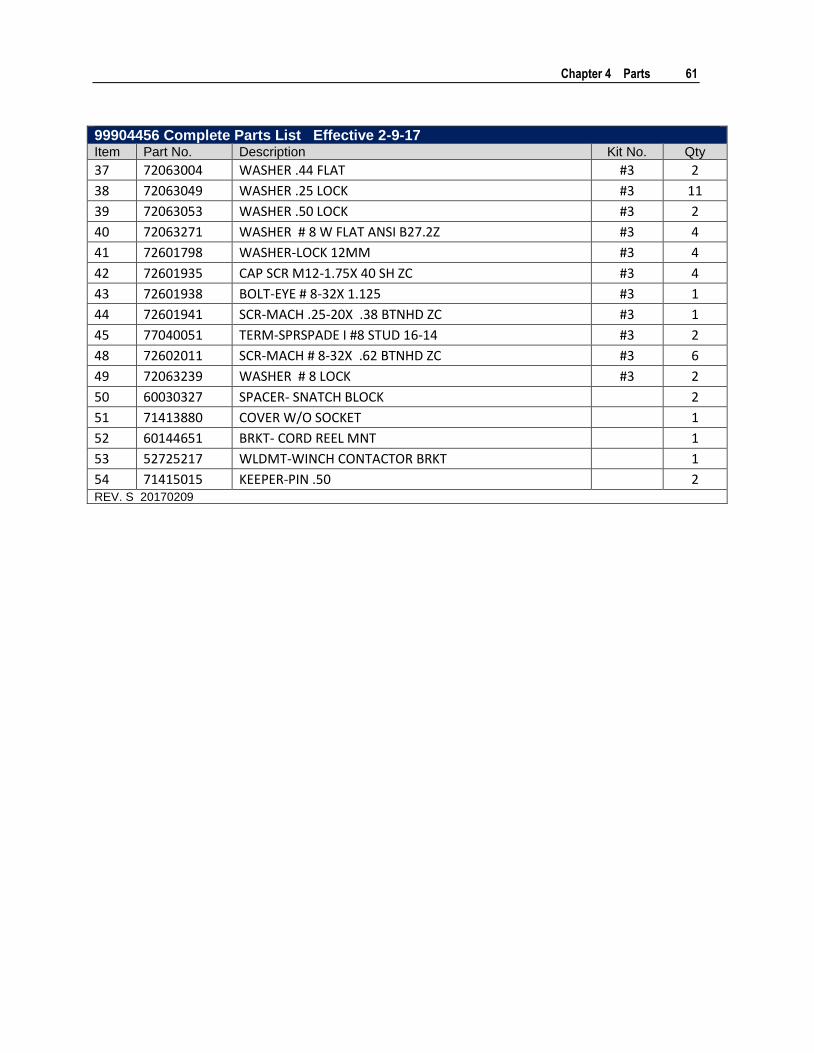
Chapter 4 Parts 61
99904456 Complete Parts List Effective 2-9-17 Item Part No. Description Kit No. Qty
37 72063004 WASHER .44 FLAT #3 2
38 72063049 WASHER .25 LOCK #3 11
39 72063053 WASHER .50 LOCK #3 2
40 72063271 WASHER # 8 W FLAT ANSI B27.2Z #3 4
41 72601798 WASHER-LOCK 12MM #3 4
42 72601935 CAP SCR M12-1.75X 40 SH ZC #3 4
43 72601938 BOLT-EYE # 8-32X 1.125 #3 1
44 72601941 SCR-MACH .25-20X .38 BTNHD ZC #3 1
45 77040051 TERM-SPRSPADE I #8 STUD 16-14 #3 2
48 72602011 SCR-MACH # 8-32X .62 BTNHD ZC #3 6
49 72063239 WASHER # 8 LOCK #3 2
50 60030327 SPACER- SNATCH BLOCK
2
51 71413880 COVER W/O SOCKET
1
52 60144651 BRKT- CORD REEL MNT
1
53 52725217 WLDMT-WINCH CONTACTOR BRKT
1
54 71415015 KEEPER-PIN .50
2 REV. S 20170209

62 IMT 6006i Technical Specifications & Parts Manual #99904532
Cord Reel-6.7m, Electric 2-Wire (70735052) Effective: 2-9-17
5.25
276” (7 m) EXTENSION
50.0”(1.27 m)
126.00”6.00
7.75
APPROVED VENDORSVENDOR VENDOR P / NZECA XXXXX

Chapter 4 Parts 63
Cord Reel Assembly, 10’5” W/Packard Connector (51727065) Effective 2-9-17
2
4,3,1
WIRE LENGTH: 126”
51727065 COMPLETE PARTS LIST Item Part No. Description Qty 1 70394069 SEAL-CABLE-GRN 20-18 GA PACKARD 2
2 70735052 CORD REEL ELECTRIC 2-WIRE 1
3 77044550 TERMINAL-FEM 18-20 GA WEATHER PACK 2
4 77044574 CONN-PKRD WEATHER PACK 2 CAV FEMALE/TOWER 1
64 IMT 6006i Technical Specifications & Parts Manual #99904532
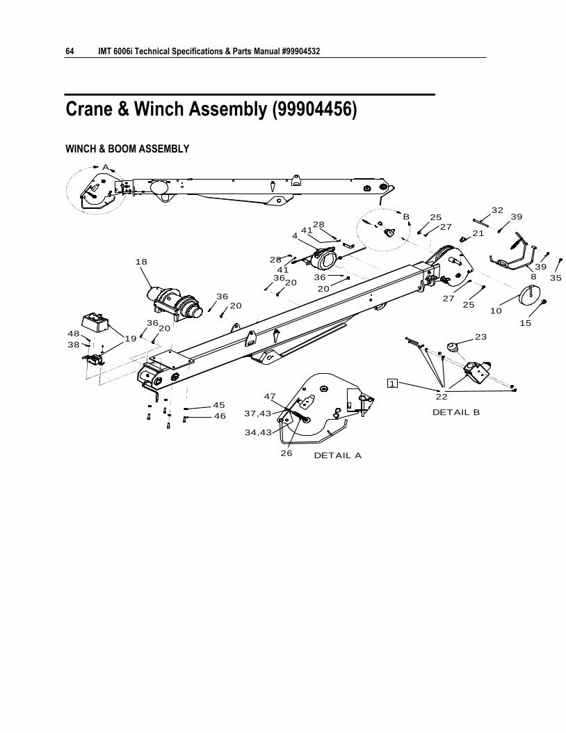
Crane & Winch Assembly (99904456)
WINCH & BOOM ASSEMBLY
A
B
47
26
22
2348
38
3620
3620
3620
36
20
4
28
41
2841
25
21
1025
3239
39
35
15
8
27
27
18
19
45
46
1
DETAIL B
DETAIL A
37,43
34,43
Chapter 4 Parts 65
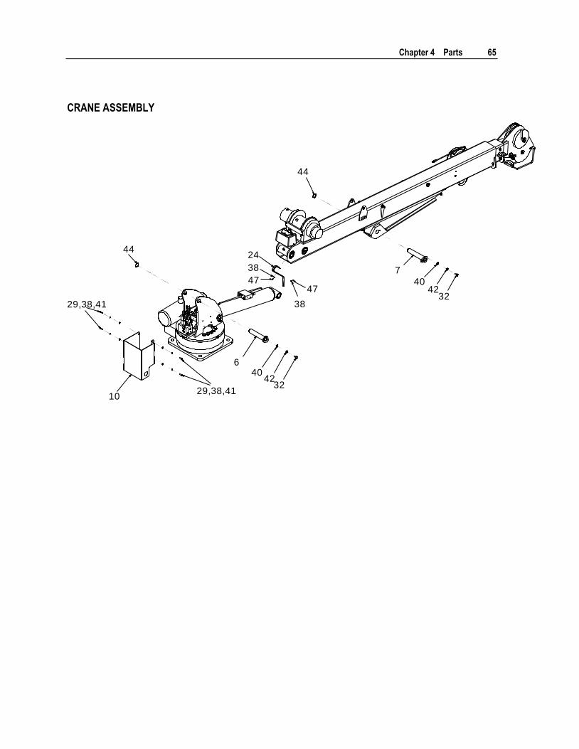
CRANE ASSEMBLY
44
44
640
4232
7
4042
32
10
47
38
47
38
24
29,38,41
29,38,41

66 IMT 6006i Technical Specifications & Parts Manual #99904532
SINGLE AND DOUBLE LINE
5
17
14
17
9
12
14
9
21
25
18
18
21
33
33
13
27
DOUBLE LINE
SINGLE LINE
NOTES (SEE REFERENCE NUMBER IN BOX):
1 PART OF WINCH.
2 CONNECT THE WIRE TERMINALS (77040051) TO "COMMON" AND "NORMALLY OPEN" ON ANTI-TWO-BLOCK SWITCH.
3 USE ANTI-SEIZE ON PINS.
4 KEEP ELECTRICAL GROUNDS FREE OF PAINT, GREASE, AND OIL
5 IF REQUIRED, USE 72063036 MACHINERY BUSHINGS BETWEEN MAST AND BOOM WHEN INSTALLING 52721425.
Chapter 4 Parts 67
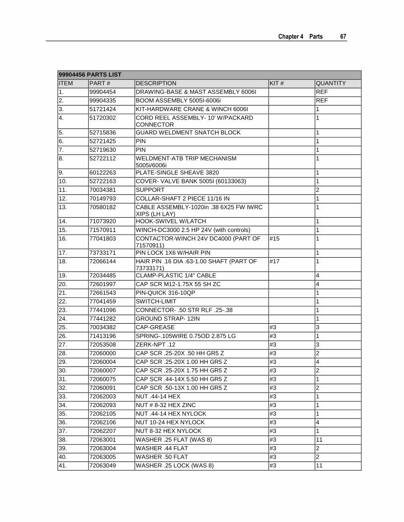
99904456 PARTS LIST
ITEM PART # DESCRIPTION KIT # QUANTITY
1. 99904454 DRAWING-BASE & MAST ASSEMBLY 6006I REF
2. 99904335 BOOM ASSEMBLY 5005I-6006i REF
3. 51721424 KIT-HARDWARE CRANE & WINCH 6006I 1
4. 51720302 CORD REEL ASSEMBLY- 10' W/PACKARD CONNECTOR
1
5. 52715836 GUARD WELDMENT SNATCH BLOCK 1
6. 52721425 PIN 1
7. 52719630 PIN 1
8. 52722112 WELDMENT-ATB TRIP MECHANISM 5005i/6006i
1
9. 60122263 PLATE-SINGLE SHEAVE 3820 1
10. 52722163 COVER- VALVE BANK 5005I (60133063) 1
11. 70034381 SUPPORT 2
12. 70149793 COLLAR-SHAFT 2 PIECE 11/16 IN 1
13. 70580182 CABLE ASSEMBLY-1020in .38 6X25 FW IWRC XIPS (LH LAY)
1
14. 71073920 HOOK-SWIVEL W/LATCH 1
15. 71570911 WINCH-DC3000 2.5 HP 24V (with controls) 1
16. 77041803 CONTACTOR-WINCH 24V DC4000 (PART OF 71570911)
#15 1
17. 73733171 PIN LOCK 1X6 W/HAIR PIN 1
18. 72066144 HAIR PIN .16 DIA .63-1.00 SHAFT (PART OF 73733171)
#17 1
19. 72034485 CLAMP-PLASTIC 1/4" CABLE 4
20. 72601997 CAP SCR M12-1.75X 55 SH ZC 4
21. 72661543 PIN-QUICK 316-10QP 1
22. 77041459 SWITCH-LIMIT 1
23. 77441096 CONNECTOR- .50 STR RLF .25-.38 1
24. 77441282 GROUND STRAP- 12IN 1
25. 70034382 CAP-GREASE #3 3
26. 71413196 SPRING-.105WIRE 0.75OD 2.875 LG #3 1
27. 72053508 ZERK-NPT .12 #3 3
28. 72060000 CAP SCR .25-20X .50 HH GR5 Z #3 2
29. 72060004 CAP SCR .25-20X 1.00 HH GR5 Z #3 4
30. 72060007 CAP SCR .25-20X 1.75 HH GR5 Z #3 2
31. 72060075 CAP SCR .44-14X 5.50 HH GR5 Z #3 1
32. 72060091 CAP SCR .50-13X 1.00 HH GR5 Z #3 2
33. 72062003 NUT .44-14 HEX #3 1
34. 72062093 NUT # 8-32 HEX ZINC #3 1
35. 72062105 NUT .44-14 HEX NYLOCK #3 1
36. 72062106 NUT 10-24 HEX NYLOCK #3 4
37. 72062207 NUT 8-32 HEX NYLOCK #3 1
38. 72063001 WASHER .25 FLAT (WAS 8) #3 11
39. 72063004 WASHER .44 FLAT #3 2
40. 72063005 WASHER .50 FLAT #3 2
41. 72063049 WASHER .25 LOCK (WAS 8) #3 11
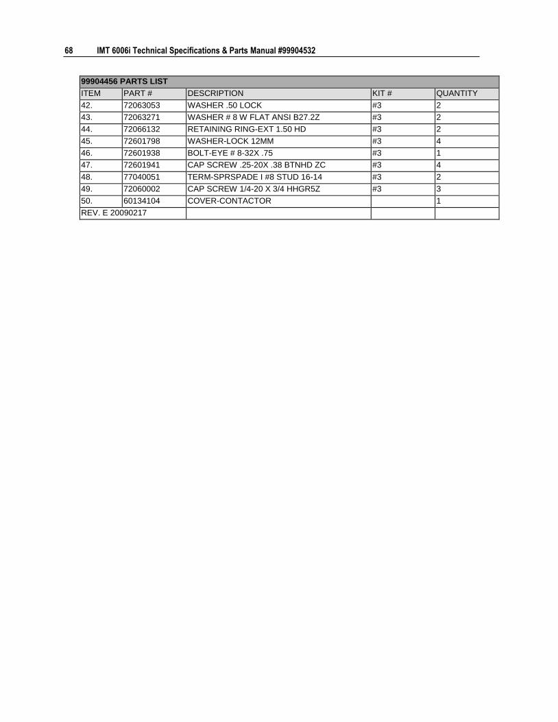
68 IMT 6006i Technical Specifications & Parts Manual #99904532
99904456 PARTS LIST
ITEM PART # DESCRIPTION KIT # QUANTITY
42. 72063053 WASHER .50 LOCK #3 2
43. 72063271 WASHER # 8 W FLAT ANSI B27.2Z #3 2
44. 72066132 RETAINING RING-EXT 1.50 HD #3 2
45. 72601798 WASHER-LOCK 12MM #3 4
46. 72601938 BOLT-EYE # 8-32X .75 #3 1
47. 72601941 CAP SCREW .25-20X .38 BTNHD ZC #3 4
48. 77040051 TERM-SPRSPADE I #8 STUD 16-14 #3 2
49. 72060002 CAP SCREW 1/4-20 X 3/4 HHGR5Z #3 3
50. 60134104 COVER-CONTACTOR 1
REV. E 20090217
Chapter 4 Parts 69
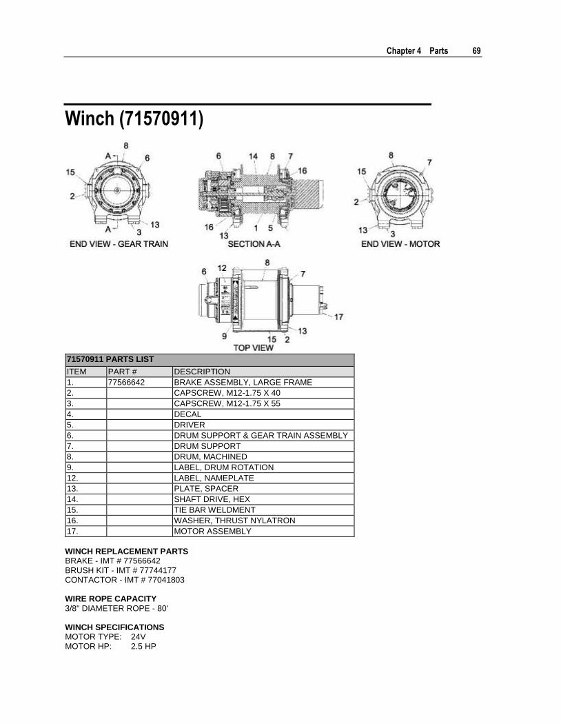
Winch (71570911)
71570911 PARTS LIST
ITEM PART # DESCRIPTION
1. 77566642 BRAKE ASSEMBLY, LARGE FRAME
2. CAPSCREW, M12-1.75 X 40
3. CAPSCREW, M12-1.75 X 55
4. DECAL
5. DRIVER
6. DRUM SUPPORT & GEAR TRAIN ASSEMBLY
7. DRUM SUPPORT
8. DRUM, MACHINED
9. LABEL, DRUM ROTATION
12. LABEL, NAMEPLATE
13. PLATE, SPACER
14. SHAFT DRIVE, HEX
15. TIE BAR WELDMENT
16. WASHER, THRUST NYLATRON
17. MOTOR ASSEMBLY
WINCH REPLACEMENT PARTS BRAKE - IMT # 77566642 BRUSH KIT - IMT # 77744177 CONTACTOR - IMT # 77041803 WIRE ROPE CAPACITY 3/8" DIAMETER ROPE - 80' WINCH SPECIFICATIONS MOTOR TYPE: 24V MOTOR HP: 2.5 HP
70 IMT 6006i Technical Specifications & Parts Manual #99904532
LAYER LOAD (LB) SPEED (FPM)
1 4,000 11.5
3 3,275 14
Power Unit (73511181)
FAN SHROUD
D.C. MOTOR(77043061)(24 VDC)
D.C. MOTOR(77043061)(24 VDC)
MOTOR SECTION
ADAPTER / RESERVOIRSECTION TUBE KIT (73734332)
(SUCTION & RETURN LINE PIPES)
RETURN LINE PIPE SUCTIONLINE PIPE
RETURNLINE PIPE,RELIEF VALVE
GEAR PUMP(73511170)
ADAPTOR
RELIEF
(73540323)VALVE
(74397392)RESERVOIR
BREATHER CAP(70733826)
Chapter 4 Parts 71
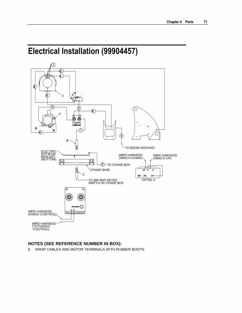
Electrical Installation (99904457)
8
10
16
6
20
11
18
19
17
8
7
A
4
2
14
3
2829
1
TO BOOM GROUND
TO CRANE BOX
WIRE HARNESS(WINCH DOWN)
WIRE HARNESS(WINCH UP)
CRANE BASE
TO 300-AMP KEYEDSWITCH IN CRANE BOX
DETAIL A
ELECTRICROTATORBRACKET(BOTTOM)
WIRE HARNESS(RADIO CONTROL)
WIRE HARNESS(TETHERED CONTROL)
NOTES (SEE REFERENCE NUMBER IN BOX):
1 WRAP CABLES AND MOTOR TERMINALS WITH RUBBER BOOTS.
72 IMT 6006i Technical Specifications & Parts Manual #99904532
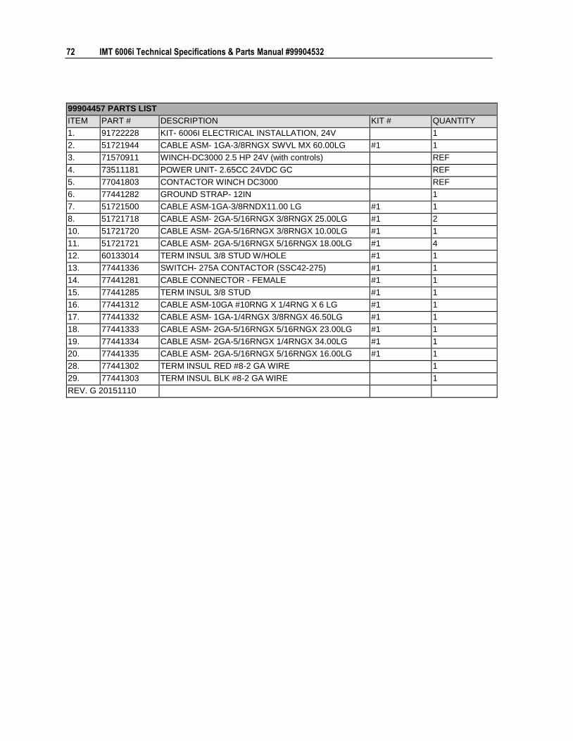
99904457 PARTS LIST
ITEM PART # DESCRIPTION KIT # QUANTITY
1. 91722228 KIT- 6006I ELECTRICAL INSTALLATION, 24V 1
2. 51721944 CABLE ASM- 1GA-3/8RNGX SWVL MX 60.00LG #1 1
3. 71570911 WINCH-DC3000 2.5 HP 24V (with controls) REF
4. 73511181 POWER UNIT- 2.65CC 24VDC GC REF
5. 77041803 CONTACTOR WINCH DC3000 REF
6. 77441282 GROUND STRAP- 12IN 1
7. 51721500 CABLE ASM-1GA-3/8RNDX11.00 LG #1 1
8. 51721718 CABLE ASM- 2GA-5/16RNGX 3/8RNGX 25.00LG #1 2
10. 51721720 CABLE ASM- 2GA-5/16RNGX 3/8RNGX 10.00LG #1 1
11. 51721721 CABLE ASM- 2GA-5/16RNGX 5/16RNGX 18.00LG #1 4
12. 60133014 TERM INSUL 3/8 STUD W/HOLE #1 1
13. 77441336 SWITCH- 275A CONTACTOR (SSC42-275) #1 1
14. 77441281 CABLE CONNECTOR - FEMALE #1 1
15. 77441285 TERM INSUL 3/8 STUD #1 1
16. 77441312 CABLE ASM-10GA #10RNG X 1/4RNG X 6 LG #1 1
17. 77441332 CABLE ASM- 1GA-1/4RNGX 3/8RNGX 46.50LG #1 1
18. 77441333 CABLE ASM- 2GA-5/16RNGX 5/16RNGX 23.00LG #1 1
19. 77441334 CABLE ASM- 2GA-5/16RNGX 1/4RNGX 34.00LG #1 1
20. 77441335 CABLE ASM- 2GA-5/16RNGX 5/16RNGX 16.00LG #1 1
28. 77441302 TERM INSUL RED #8-2 GA WIRE 1
29. 77441303 TERM INSUL BLK #8-2 GA WIRE 1
REV. G 20151110
73
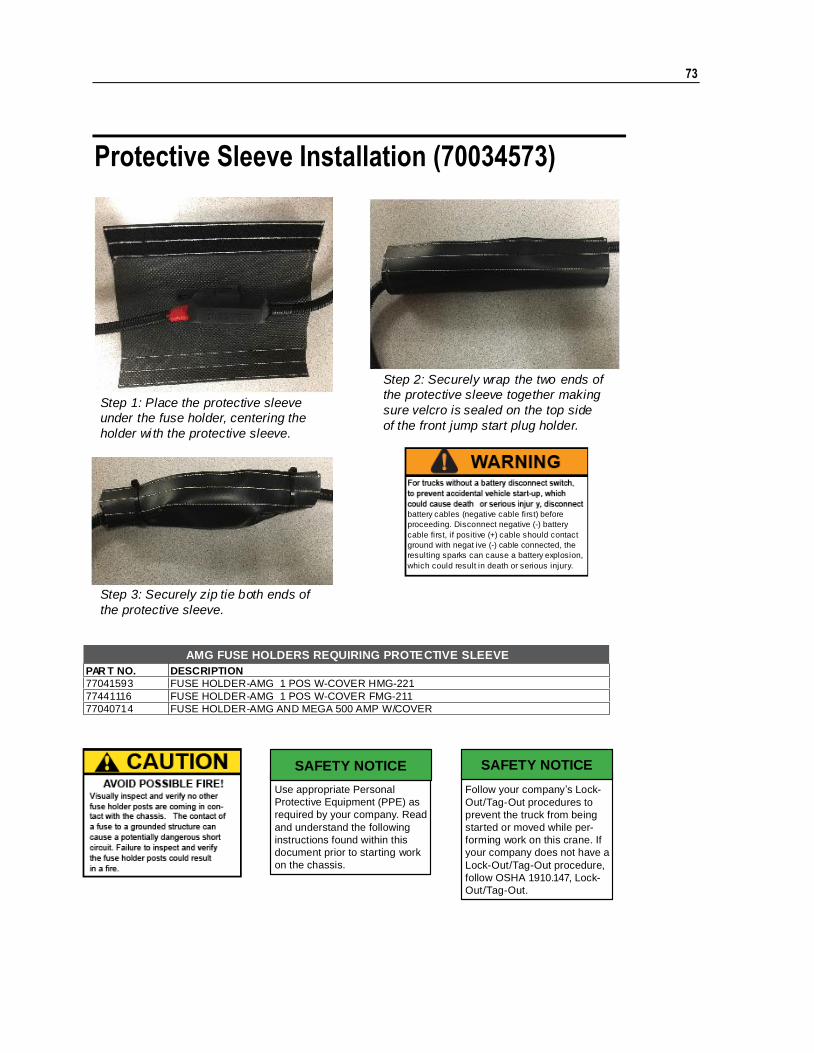
Protective Sleeve Installation (70034573)
AMG FUSE HOLDERS REQUIRING PROTECTIVE SLEEVE
PAR T NO. DESCRIPTION
77041593 FUSE HOLDER-AMG 1 POS W-COVER HMG-221
77441116 FUSE HOLDER-AMG 1 POS W-COVER FMG-211
77040714 FUSE HOLDER-AMG AND MEGA 500 AMP W/COVER
Step 1: Place the protective sleeve
under the fuse holder, centering the
holder wi th the protective sleeve.
Step 2: Securely wrap the two ends of
the protective sleeve together making
sure velcro is sealed on the top side
of the front jump start plug holder.
Step 3: Securely zip tie both ends of
the protective sleeve.
Follow your company’s Lock-
Out/Tag-Out procedures to
prevent the truck from being
started or moved while per-
forming work on this crane. If
your company does not have a
Lock-Out/Tag-Out procedure,
follow OSHA 1910.147, Lock-
Out/Tag-Out.
SAFETY NOTICE
Use appropriate Personal
Protective Equipment (PPE) as
required by your company. Read
and understand the following
instructions found within this
document prior to starting work
on the chassis.
SAFETY NOTICE
WARNINGFor trucks without a battery disconnect switch,
to prevent accidental vehicle start-up, which
battery cables (negative cable first) before
proceeding. Disconnect negative (-) battery
cable first, if positive (+) cable should contact
ground with negat ive (-) cable connected, the
resulting sparks can cause a battery explosion,
which could result in death or serious injury.
74 IMT 6006i Technical Specifications & Parts Manual #99904532
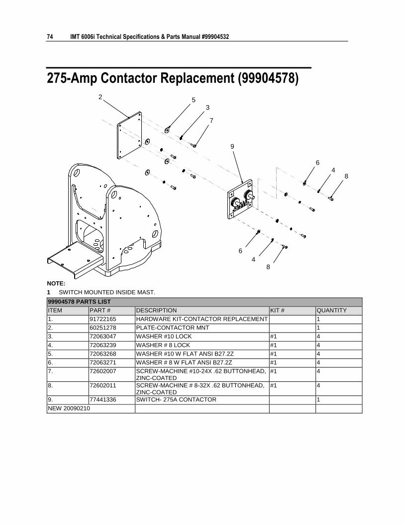
275-Amp Contactor Replacement (99904578) 2
9
35
7
64
8
6
48
NOTE:
1 SWITCH MOUNTED INSIDE MAST.
99904578 PARTS LIST
ITEM PART # DESCRIPTION KIT # QUANTITY
1. 91722165 HARDWARE KIT-CONTACTOR REPLACEMENT 1
2. 60251278 PLATE-CONTACTOR MNT 1
3. 72063047 WASHER #10 LOCK #1 4
4. 72063239 WASHER # 8 LOCK #1 4
5. 72063268 WASHER #10 W FLAT ANSI B27.2Z #1 4
6. 72063271 WASHER # 8 W FLAT ANSI B27.2Z #1 4
7. 72602007 SCREW-MACHINE #10-24X .62 BUTTONHEAD, ZINC-COATED
#1 4
8. 72602011 SCREW-MACHINE # 8-32X .62 BUTTONHEAD, ZINC-COATED
#1 4
9. 77441336 SWITCH- 275A CONTACTOR 1
NEW 20090210
Chapter 4 Parts 75
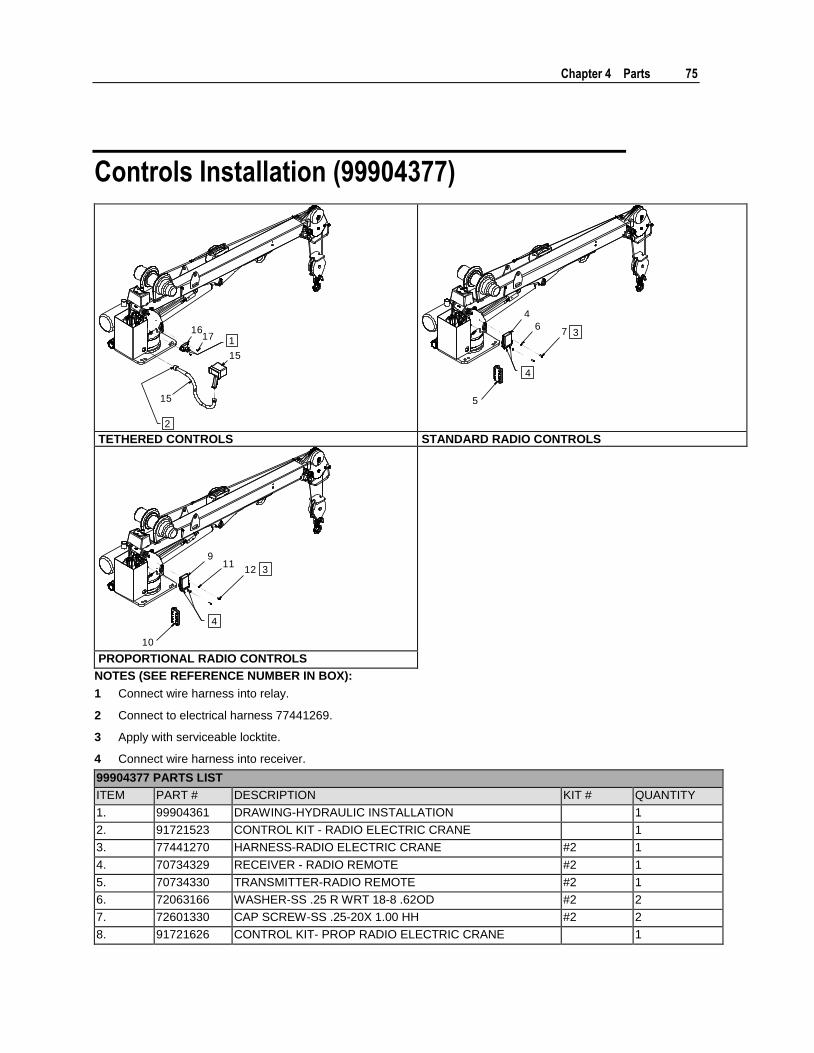
Controls Installation (99904377)
1716
15
15
1
2
4
6
5
7 3
4
TETHERED CONTROLS STANDARD RADIO CONTROLS
911
12
10
3
4
PROPORTIONAL RADIO CONTROLS
NOTES (SEE REFERENCE NUMBER IN BOX):
1 Connect wire harness into relay.
2 Connect to electrical harness 77441269.
3 Apply with serviceable locktite.
4 Connect wire harness into receiver.
99904377 PARTS LIST
ITEM PART # DESCRIPTION KIT # QUANTITY
1. 99904361 DRAWING-HYDRAULIC INSTALLATION 1
2. 91721523 CONTROL KIT - RADIO ELECTRIC CRANE 1
3. 77441270 HARNESS-RADIO ELECTRIC CRANE #2 1
4. 70734329 RECEIVER - RADIO REMOTE #2 1
5. 70734330 TRANSMITTER-RADIO REMOTE #2 1
6. 72063166 WASHER-SS .25 R WRT 18-8 .62OD #2 2
7. 72601330 CAP SCREW-SS .25-20X 1.00 HH #2 2
8. 91721626 CONTROL KIT- PROP RADIO ELECTRIC CRANE 1
76 IMT 6006i Technical Specifications & Parts Manual #99904532
99904377 PARTS LIST
ITEM PART # DESCRIPTION KIT # QUANTITY
9. 70734347 RECEIVER-PROP RADIO ELECTRIC CRANE CRANE #8 1
10. 70734348 TRANSMITTER-PROP RADIO ELECTRIC CRANE #8 1
11. 72063166 WASHER-SS .25 R WRT 18-8 .62OD #8 2
12. 72601330 CAP SCREW-SS .25-20X 1.00 HH #8 2
13. 91721524 CONTROL KIT - TETHERED ELECTRIC CRANE 1
14. 77441269 HARNESS-TETHERED ELELCTRICAL CRANES #13 1
15. 51721502 HANDLE ASSEMBLY-TETHERED ELECTRIC CRANES #13 1
16. 71413190 RELAY-2 RELAY MODULE #13 1
17. 72601940 CAP SCREW .10-24X .50 BTNHD ZC #13 2
REV. A 20080527
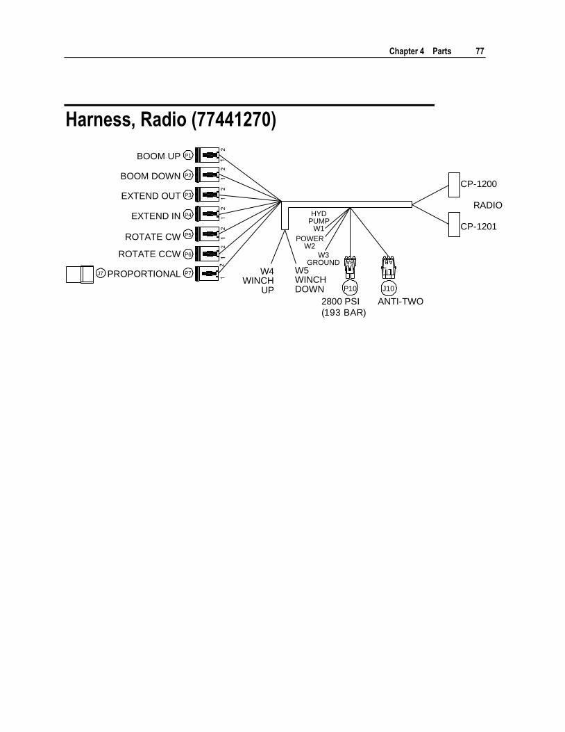
Chapter 4 Parts 77
Harness, Radio (77441270)
W4WINCH
UP
W5WINCHDOWN
W3GROUND
POWERW2
HYDPUMP
W1
P10 J10
ANTI-TWO2800 PSI
(193 BAR)
RADIO
CP-1200
CP-1201
BOOM UP
BOOM DOWN
EXTEND OUT
EXTEND IN
ROTATE CW
ROTATE CCW
PROPORTIONAL
P1
P2
P3
P4
P5
P6
P7J7

78 IMT 6006i Technical Specifications & Parts Manual #99904532
SCHEMATIC, HARNESS, RADIO (77441270)
21
21
BA
2
21
1
AB
2
21
1
CP-1200RADIO
RECEIVERINTERFACE
(GRAY)
CP-1201RADIO
RECEIVERINTERFACE
(BLACK)
N/C
N/C
GROUND
PROPORTIONAL
N/C
POWER (RADIO)
BOOM UP
BOOM DOWN
EXTEND OUT
WINCH UP
EXTEND IN
WINCH DOWN
1
2
3
4
5
6
7
8
9
10
11
12
ROTATE CW
ROTATE CCW
HYD PUMP
N/C
N/C
N/C
N/C
N/C
N/C
N/C
N/C
A2B/OVERLOAD
1
2
3
4
5
6
7
8
9
10
11
12
HYD PUMP
POWER
GROUND
W1
W2
W3
SPLICE G
SPLICE G SPLICE GSPLICE G SPLICE G SPLICE G
SPLICE P
SPLICE G
12
P6 ROTATE CCW
P5 ROTATE CW
P10 2800 PSI(193 BAR)
J10 ANTI-TWO
W5 WINCH DOWN
P4 EXTEND IN
W4 WINCH UP
P3 EXTEND OUT
P2 BOOM DOWN
P1 BOOM UP
P7 PROPORTIONAL
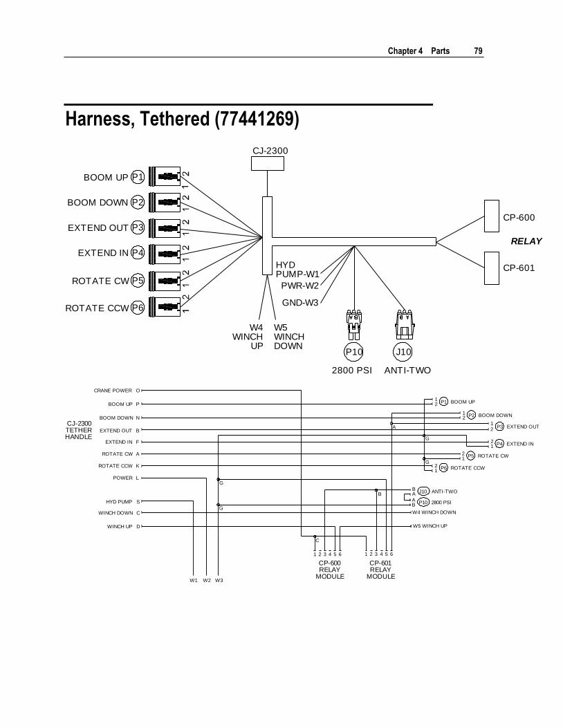
Chapter 4 Parts 79
Harness, Tethered (77441269)
2800 PSI ANTI-TWO
P10 J10
W4WINCH
UP
W5WINCHDOWN
HYDPUMP-W1
PWR-W2
GND-W3
RELAY
CP-601
CP-600
CJ-2300
BOOM UP
BOOM DOWN
EXTEND OUT
EXTEND IN
ROTATE CW
ROTATE CCW
P1
P2
P3
P4
P5
P6
A
W4 WINCH DOWN
12 P1 BOOM UP
12 P2 BOOM DOWN
2P3 EXTEND OUT
21 P4 EXTEND IN
1
21
P6 ROTATE CCW
21
P5 ROTATE CW
AB P10 2800 PSI
BA J10 ANTI-TWO
W5 WINCH UP
A
B
G
G
C
1 2 3 4 5 6 1 2 3 4 5 6
CP-600RELAY
MODULE
CP-601RELAY
MODULE
G
G
W1 W2 W3
CRANE POWER
BOOM UP
BOOM DOWN
EXTEND OUT
EXTEND IN
ROTATE CW
ROTATE CCW
POWER
O
P
N
B
F
K
L
CJ-2300TETHERHANDLE
HYD PUMP
WINCH DOWN
WINCH UP
S
C
D
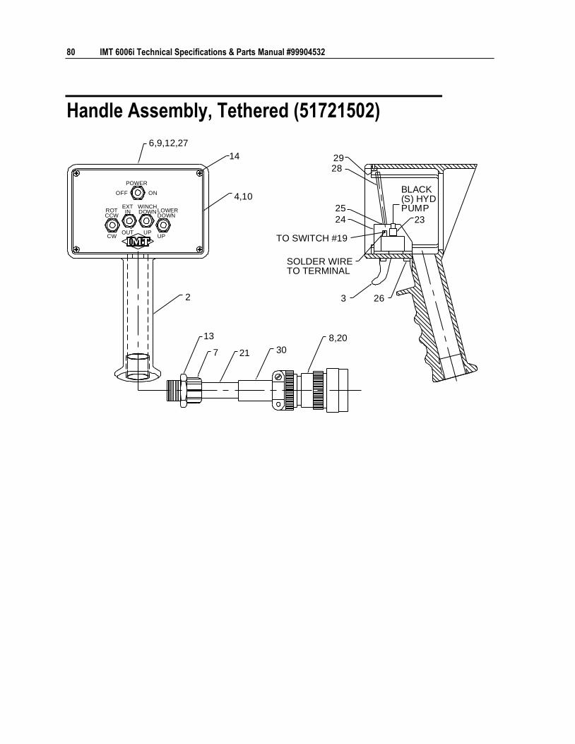
80 IMT 6006i Technical Specifications & Parts Manual #99904532
Handle Assembly, Tethered (51721502)
2
13
7 21 30
8,20
3 26
23
BLACK(S) HYDPUMP
TO SWITCH #19
SOLDER WIRETO TERMINAL
4,10
25
24
282914
6,9,12,27
POWER
OFF ON
ROTCCW
CW
EXTIN
OUT
WINCHDOWN
UP
LOWERDOWN
UP
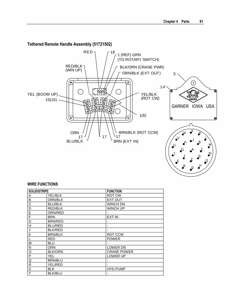
Chapter 4 Parts 81
Tethered Remote Handle Assembly (51721502)
5
14
181 (REF) GRN
(TO ROTARY SWITCH)
BLK/ORN (CRANE PWR)
ORN/BLK (EXT OUT)
YEL/BLK(ROT CW)
1(6)
ORN17
BLU/BLK17
BRN/BLK (ROT CCW)17
BRN (EXT IN)
RE D
RED/BLK(WIN UP)
15(16)
YEL (BOOM UP)
WIRE FUNCTIONS
SOLID/STRIPE FUNCTION
A YEL/BLK ROT CW
B ORN/BLK EXT OUT
C BLU/BLK WINCH DN
D RED/BLK WINCH UP
E ORN/RED -
F BRN EXT IN
G BRN/RED -
H BLU/RED -
J BLK/RED -
K BRN/BLK ROT CCW
L RED POWER
M BLU -
N ORN LOWER DN
O BLK/ORN CRANE POWER
P YEL LOWER UP
Q BRN/BLU -
R YEL/RED -
S BLK HYD PUMP
T BLK/BLU -
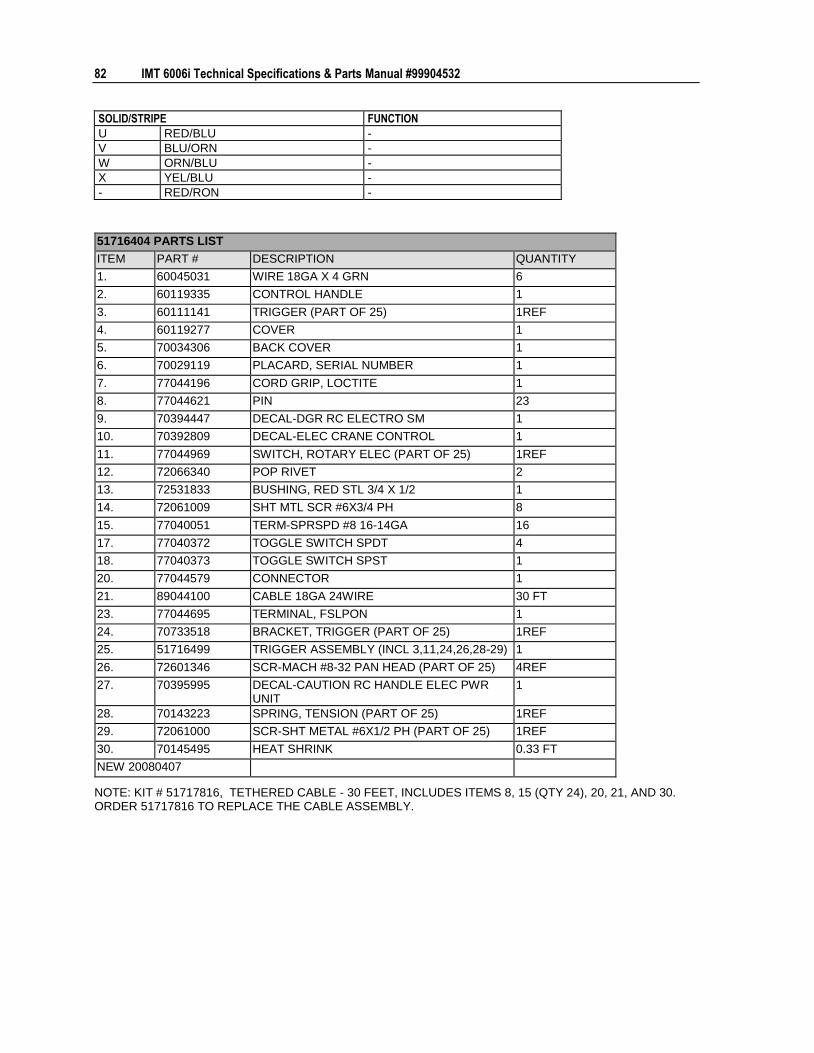
82 IMT 6006i Technical Specifications & Parts Manual #99904532
SOLID/STRIPE FUNCTION
U RED/BLU -
V BLU/ORN -
W ORN/BLU -
X YEL/BLU -
- RED/RON -
51716404 PARTS LIST
ITEM PART # DESCRIPTION QUANTITY
1. 60045031 WIRE 18GA X 4 GRN 6
2. 60119335 CONTROL HANDLE 1
3. 60111141 TRIGGER (PART OF 25) 1REF
4. 60119277 COVER 1
5. 70034306 BACK COVER 1
6. 70029119 PLACARD, SERIAL NUMBER 1
7. 77044196 CORD GRIP, LOCTITE 1
8. 77044621 PIN 23
9. 70394447 DECAL-DGR RC ELECTRO SM 1
10. 70392809 DECAL-ELEC CRANE CONTROL 1
11. 77044969 SWITCH, ROTARY ELEC (PART OF 25) 1REF
12. 72066340 POP RIVET 2
13. 72531833 BUSHING, RED STL 3/4 X 1/2 1
14. 72061009 SHT MTL SCR #6X3/4 PH 8
15. 77040051 TERM-SPRSPD #8 16-14GA 16
17. 77040372 TOGGLE SWITCH SPDT 4
18. 77040373 TOGGLE SWITCH SPST 1
20. 77044579 CONNECTOR 1
21. 89044100 CABLE 18GA 24WIRE 30 FT
23. 77044695 TERMINAL, FSLPON 1
24. 70733518 BRACKET, TRIGGER (PART OF 25) 1REF
25. 51716499 TRIGGER ASSEMBLY (INCL 3,11,24,26,28-29) 1
26. 72601346 SCR-MACH #8-32 PAN HEAD (PART OF 25) 4REF
27. 70395995 DECAL-CAUTION RC HANDLE ELEC PWR UNIT
1
28. 70143223 SPRING, TENSION (PART OF 25) 1REF
29. 72061000 SCR-SHT METAL #6X1/2 PH (PART OF 25) 1REF
30. 70145495 HEAT SHRINK 0.33 FT
NEW 20080407
NOTE: KIT # 51717816, TETHERED CABLE - 30 FEET, INCLUDES ITEMS 8, 15 (QTY 24), 20, 21, AND 30. ORDER 51717816 TO REPLACE THE CABLE ASSEMBLY.
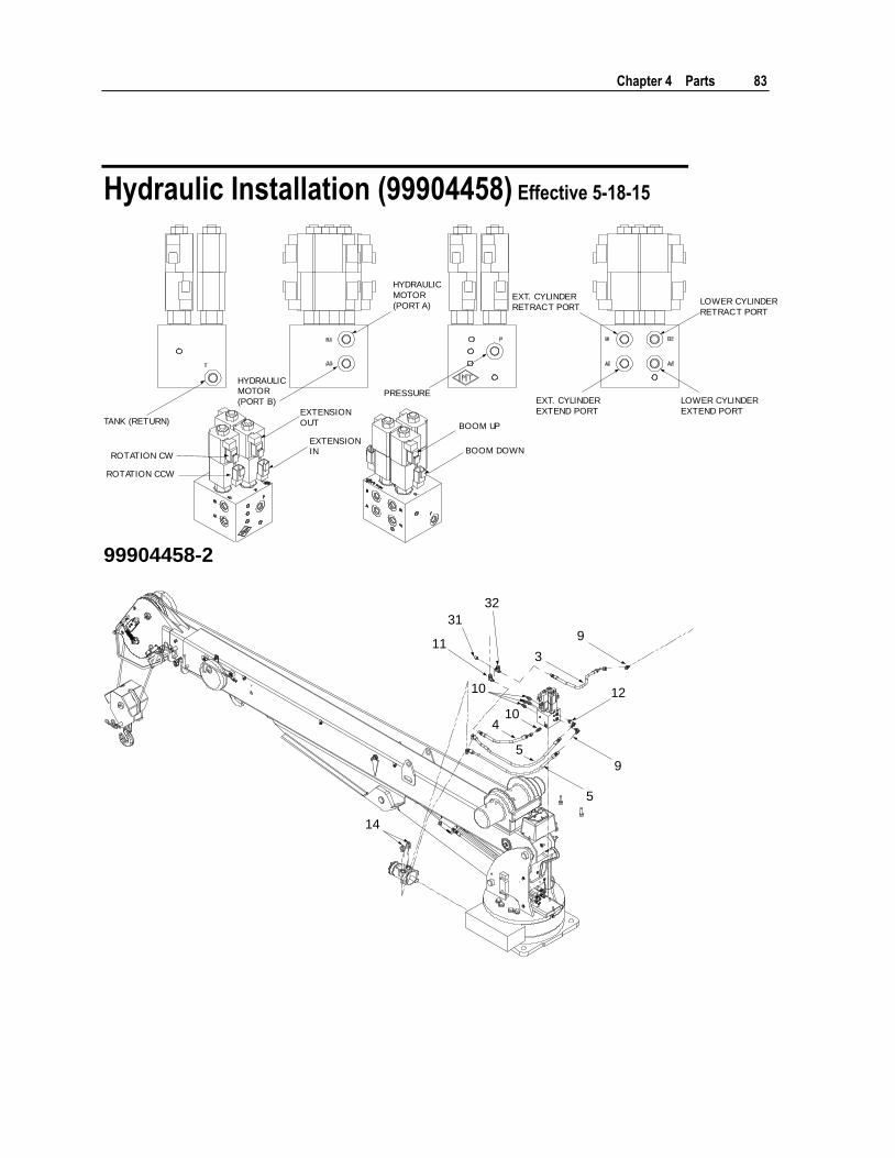
Chapter 4 Parts 83
Hydraulic Installation (99904458) Effective 5-18-15
BOOM UP
BOOM DOWN
EXT. CYLINDER
EXTEND PORT
LOWER CYLINDER
EXTEND PORT
LOWER CYLINDER
RETRACT PORT
EXT. CYLINDER
RETRACT PORT
PRESSURE
HYDRAULIC
MOTOR
(PORT A)
HYDRAULICMOTOR
(PORT B)
EXTENSION
OUT
EXTENSIONIN
TANK (RETURN)
ROTATION CW
ROTATION CCW
99904458-2
14
10
10
11
31
32
3
9
12
9
5
4
5
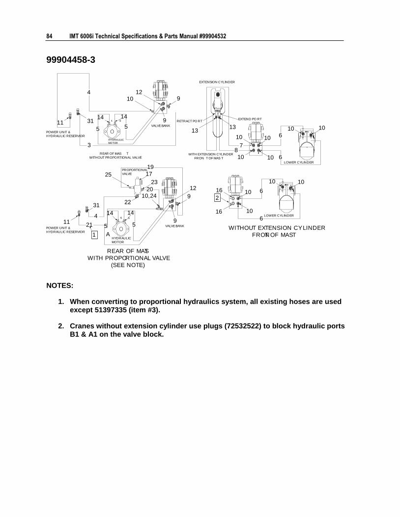
84 IMT 6006i Technical Specifications & Parts Manual #99904532
99904458-3
2
25
19
17
23
202410,
22
5
12
9
9
16 10
6
6
1016
10
1010
6
6
10108
7
10 10
1313
9
9
1012
14
5
14
5
31
3
4
11
10
1414
A
114
21 5
31
WITHOUT EXTENSION CYLINDER
FRONT OF MAST
REAR OF MAST
WITH PROPORTIONAL VALVE
(SEE NOTE)
LOWER CYLINDER
LOWER CYLINDER
VALVE BANK
VALVE BANK
WITH EXTENSION CYLINDER
FRON T OF MAS T
REAR OF MAS T
WITHOUT PROPORTIONAL VALVE
POWER UNIT &
HYDRAULIC RESERVIOR
POWER UNIT &
HYDRAULIC RESERVIOR
EXTENSION CYLINDER
EXTEND PO RTRETRACT PO RT
1HYDRAULIC
MOTOR
HYDRAULIC
MOTOR
PROPORTIONAL
VALVE
NOTES:
1. When converting to proportional hydraulics system, all existing hoses are used except 51397335 (item #3).
2. Cranes without extension cylinder use plugs (72532522) to block hydraulic ports B1 & A1 on the valve block.
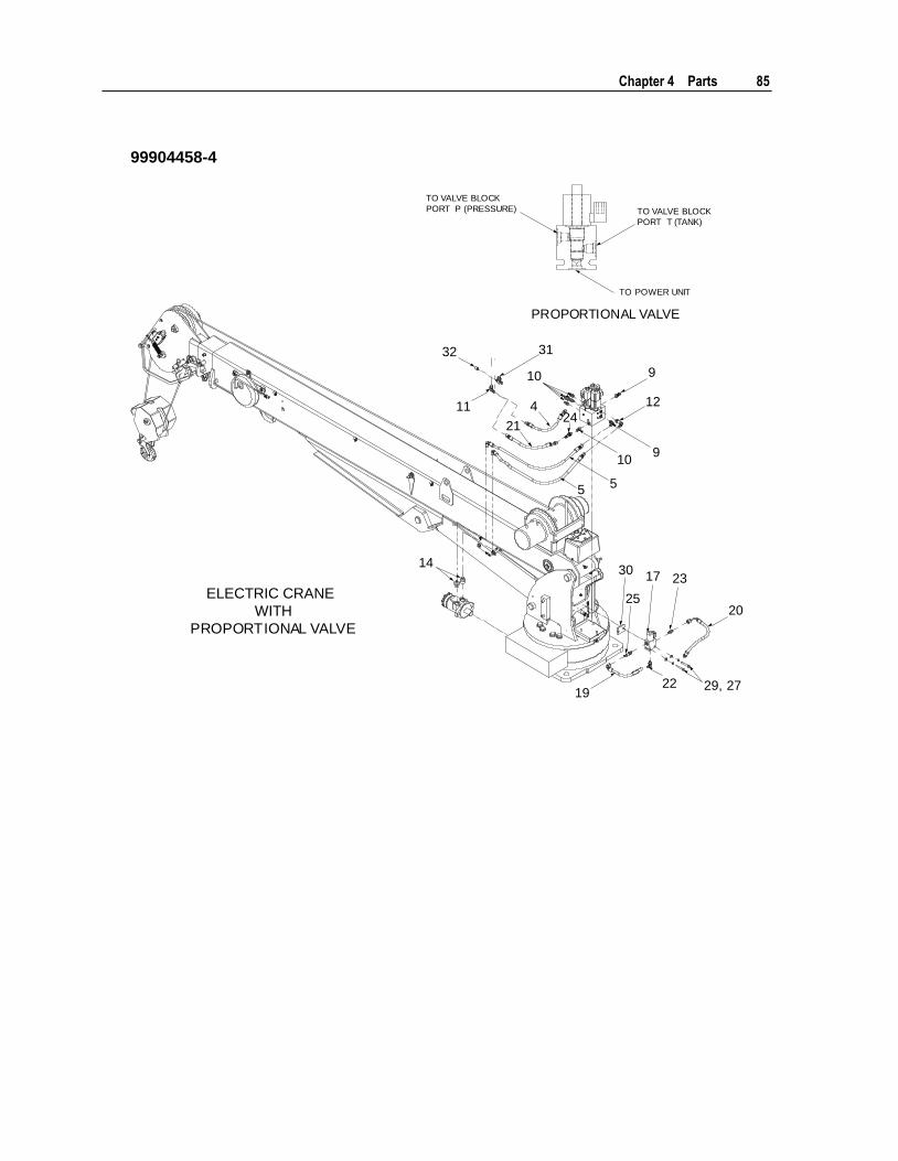
Chapter 4 Parts 85
99904458-4
TO VALVE BLOCK
PORT P (PRESSURE) TO VALVE BLOCK
PORT T (TANK)
TO POWER UNIT
PROPORTIONAL VALVE
ELECTRIC CRANE
WITH
PROPORTIONAL VALVE
9
12
910
55
1430
25
17 23
20
29, 272219
10
4
2124
11
3132
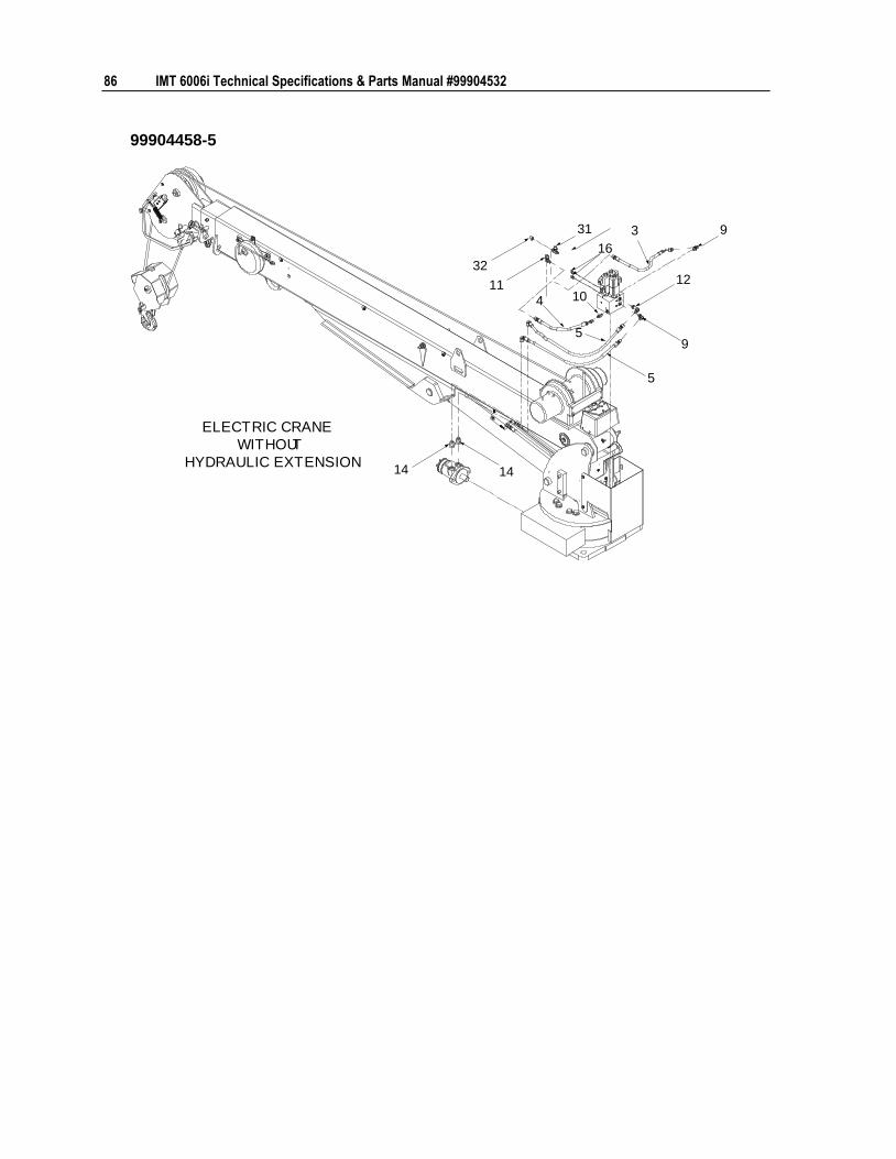
86 IMT 6006i Technical Specifications & Parts Manual #99904532
99904458-5
14 14
11
32
31
16
3 9
12
9
5
4 10
5
ELECTRIC CRANE
WITHOUT
HYDRAULIC EXTENSION
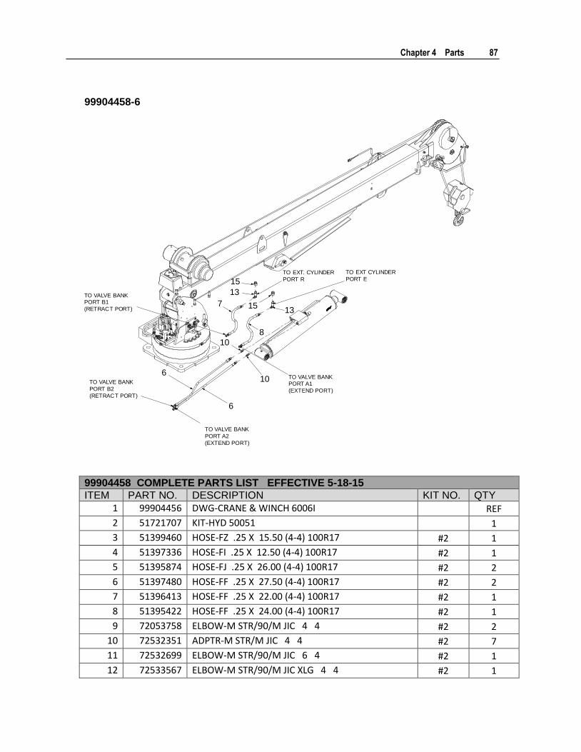
Chapter 4 Parts 87
99904458-6
10
6
10
6
7
15
13
1513
8
TO VALVE BANKPORT B1
(RETRACT PORT)
TO VALVE BANKPORT A1
(EXTEND PORT)
TO EXT. CYLINDER
PORT R
TO EXT CYLINDER
PORT E
TO VALVE BANK
PORT B2
(RETRACT PORT)
TO VALVE BANK
PORT A2
(EXTEND PORT)
99904458 COMPLETE PARTS LIST EFFECTIVE 5-18-15
ITEM PART NO. DESCRIPTION KIT NO. QTY
1 99904456 DWG-CRANE & WINCH 6006I
REF
2 51721707 KIT-HYD 50051
1
3 51399460 HOSE-FZ .25 X 15.50 (4-4) 100R17 #2 1
4 51397336 HOSE-FI .25 X 12.50 (4-4) 100R17 #2 1
5 51395874 HOSE-FJ .25 X 26.00 (4-4) 100R17 #2 2
6 51397480 HOSE-FF .25 X 27.50 (4-4) 100R17 #2 2
7 51396413 HOSE-FF .25 X 22.00 (4-4) 100R17 #2 1
8 51395422 HOSE-FF .25 X 24.00 (4-4) 100R17 #2 1
9 72053758 ELBOW-M STR/90/M JIC 4 4 #2 2
10 72532351 ADPTR-M STR/M JIC 4 4 #2 7
11 72532699 ELBOW-M STR/90/M JIC 6 4 #2 1
12 72533567 ELBOW-M STR/90/M JIC XLG 4 4 #2 1

88 IMT 6006i Technical Specifications & Parts Manual #99904532
99904458 COMPLETE PARTS LIST EFFECTIVE 5-18-15
ITEM PART NO. DESCRIPTION KIT NO. QTY
13 72534567 ELBOW-M STR/90/M JIC XLG 6 4 #2 2
14 72533589 ADPTR-M STR/M JIC 10 4 #2 2
15 72533052 ADPTR-M STR/F STR 8 6 #2 2
16 72532522 PLUG-STR HEX HD STL .44
2
17 73540325 VALVE-PROP FLOW CNTRL 12V ELEC CRANE
1
18 91721626 KIT-HYD 50051 PROP
1
19 51395663 HOSE-FJ .25 X 14.00 (4-4) 100R17 #17 1
20 51397434 HOSE-FZ .25 X 16.00 (4-4) 100R17 #17 2
21 51397452 HOSE-FI .25 X 11.50 (4-4) 100R17 #17 1
22 72053758 ELBOW-M STR/90/M JIC 4 4 #17 1
23 72532351 ADPTR-M STR/M JIC 4 4 #17 1
24 72532981 TEE-SWVL NUT RUN JIC 4 #17 1
25 72534477 ADPTR-M STR/M JIC 4 4 XLG #17 1
26 51722635 KIT-HRDW PROP CNTRL VALVE 5005/6006
1
27 72063001 WASHER .25 FLAT #25 2
28 72063049 WASHER .25 LOCK #25 2
29 72060008 CAP SCR .25-20X 2.00 HH GR5 Z #25 2
30 60134907 PLATE-SPACER PROP VLVE 5005/6006
1
31 72532674 CAP-JIC STL 4 ( .44 THD) #2 1
32 72534714 TEE-STL JIC/STR/JIC 4 6 4 BRANCH #2 1
REV. J 20160525

Chapter 4 Parts 89
99904458
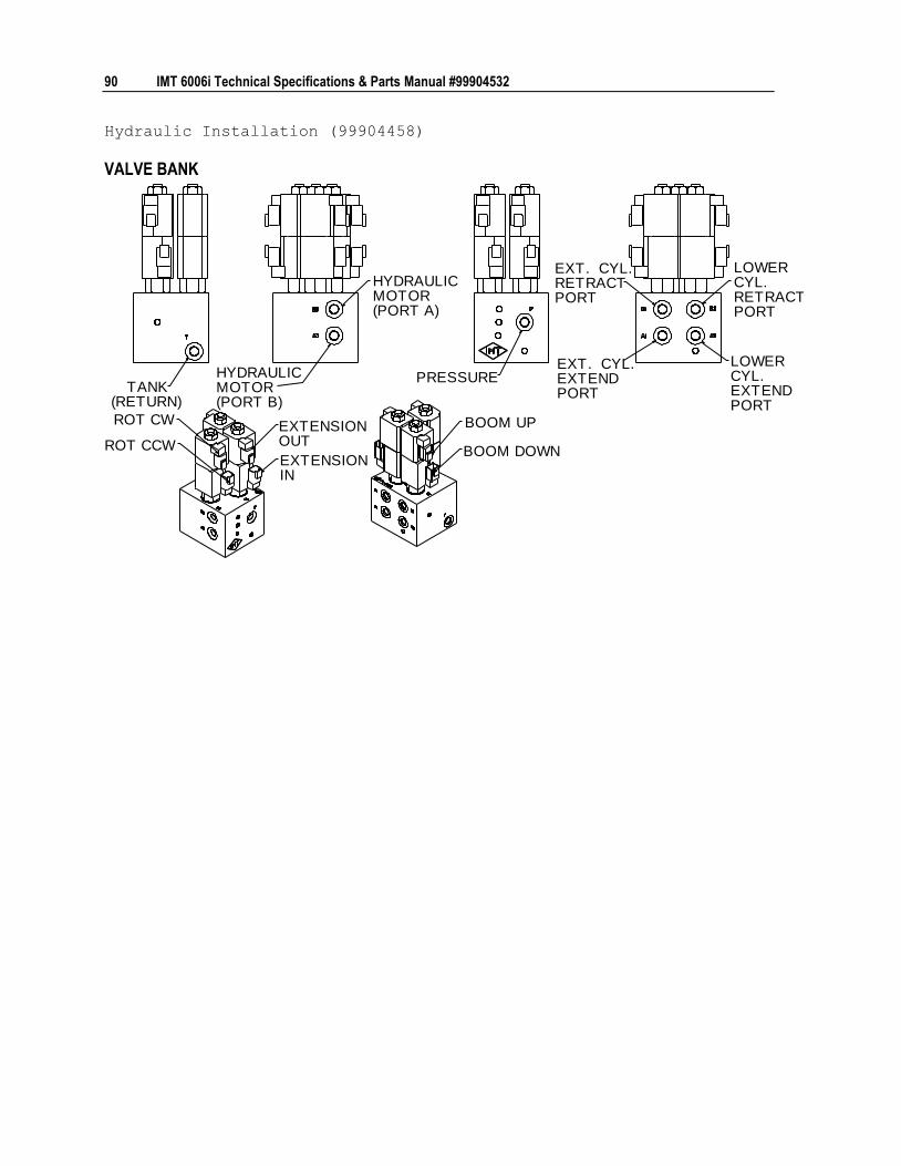
90 IMT 6006i Technical Specifications & Parts Manual #99904532
Hydraulic Installation (99904458)
VALVE BANK
HYDRAULICMOTOR(PORT A)
HYDRAULICMOTOR(PORT B)
PRESSURE
EXT. CYL.RETRACTPORT
EXT. CYL.EXTENDPORT
LOWERCYL.RETRACTPORT
LOWERCYL.EXTENDPORT
BOOM UP
BOOM DOWN
TANK(RETURN)
ROT CW
ROT CCW
EXTENSIONOUT
EXTENSIONIN
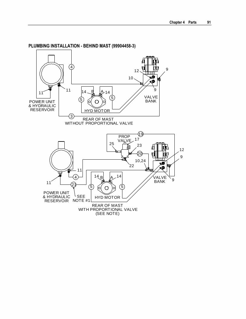
Chapter 4 Parts 91
PLUMBING INSTALLATION - BEHIND MAST (99904458-3)
4
55
3
4
21 5
19
20
AB1111 14 14
9
10
12
9
11
11
14 14
22
2325
9
9
12
17
AB
POWER UNIT& HYDRAULICRESERVOIR
POWER UNIT& HYDRAULICRESERVOIR
SEENOTE #1
REAR OF MASTWITHOUT PROPORTIONAL VALVE
REAR OF MASTWITH PROPORTIONAL VALVE
(SEE NOTE)
HYD MOTOR
HYD MOTOR
5
VALVEBANK
PROPVALVE
VALVEBANK
10,24
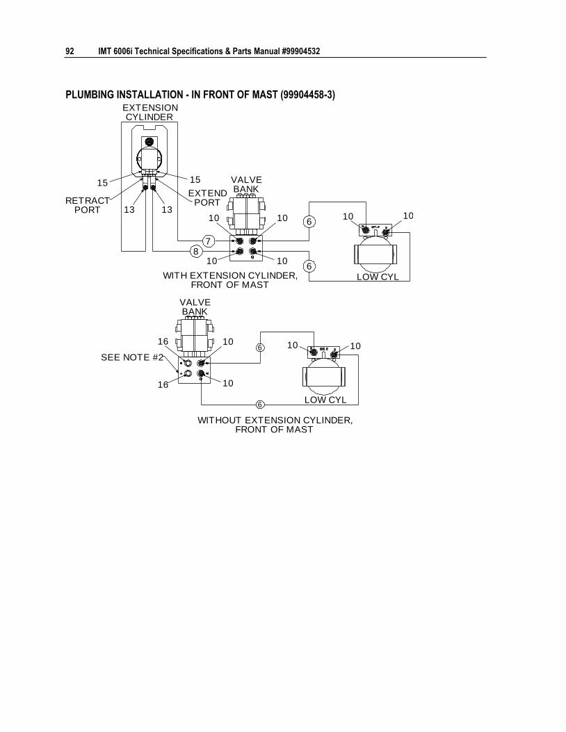
92 IMT 6006i Technical Specifications & Parts Manual #99904532
PLUMBING INSTALLATION - IN FRONT OF MAST (99904458-3)
6
6
87
6
6
131310 10
10 10
1010
101016
16
10
10
1515
WITH EXTENSION CYLINDER,FRONT OF MAST
WITHOUT EXTENSION CYLINDER,FRONT OF MAST
LOW CYL
LOW CYL
VALVEBANK
VALVEBANK
SEE NOTE #2
RETRACTPORT
EXTENDPORT
EXTENSIONCYLINDER
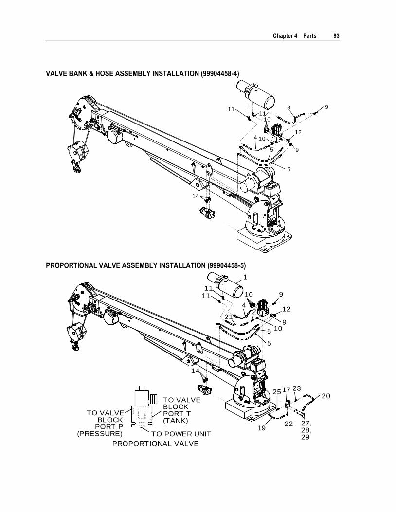
Chapter 4 Parts 93
VALVE BANK & HOSE ASSEMBLY INSTALLATION (99904458-4)
1111
3 9
10
4 1012
9
5
5
14
PROPORTIONAL VALVE ASSEMBLY INSTALLATION (99904458-5)
1111
4
2124
10
5
5
12
9
910
14
20
19
252317
22
1
TO VALVEBLOCK
PORT P(PRESSURE)
TO VALVEBLOCKPORT T(TANK)
TO POWER UNIT
PROPORTIONAL VALVE
27,28,29
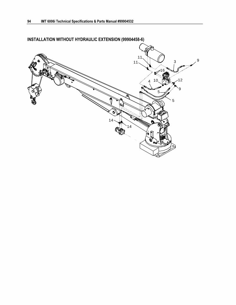
94 IMT 6006i Technical Specifications & Parts Manual #99904532
INSTALLATION WITHOUT HYDRAULIC EXTENSION (99904458-6)
11
113 9
4 10 12
95
5
14
14
16
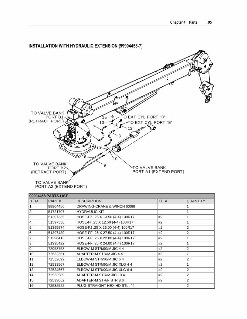
Chapter 4 Parts 95
INSTALLATION WITH HYDRAULIC EXTENSION (99904458-7)
13
13
10
10
6
6
15
15
8
7
TO VALVE BANKPORT A1 (EXTEND PORT)
TO EXT CYL PORT "E"
TO EXT CYL PORT "R"TO VALVE BANK
PORT B1(RETRACT PORT)
TO VALVE BANKPORT B2
(RETRACT PORT)
TO VALVE BANKPORT A2 (EXTEND PORT)
99904458 PARTS LIST
ITEM PART # DESCRIPTION KIT # QUANTITY
1. 99904456 DRAWING-CRANE & WINCH 6006I 1
2. 51721707 HYDRAULIC KIT 1
3. 51397335 HOSE-FZ .25 X 13.50 (4-4) 100R17 #2 1
4. 51397336 HOSE-FI .25 X 12.50 (4-4) 100R17 #2 1
5. 51395874 HOSE-FJ .25 X 26.00 (4-4) 100R17 #2 2
6. 51397480 HOSE-FF .25 X 27.50 (4-4) 100R17 #2 2
7. 51396413 HOSE-FF .25 X 22.00 (4-4) 100R17 #2 1
8. 51395422 HOSE-FF .25 X 24.00 (4-4) 100R17 #2 1
9. 72053758 ELBOW-M STR/90/M JIC 4 4 #2 2
10. 72532351 ADAPTER-M STR/M JIC 4 4 #2 7
11. 72532699 ELBOW-M STR/90/M JIC 6 4 #2 2
12. 72533567 ELBOW-M STR/90/M JIC XLG 4 4 #2 1
13. 72534567 ELBOW-M STR/90/M JIC XLG 6 4 #2 2
14. 72533589 ADAPTER-M STR/M JIC 10 4 #2 2
15. 72533052 ADAPTER-M STR/F STR 8 6 #2 2
16. 72532522 PLUG-STRAIGHT HEX HD STL .44 2
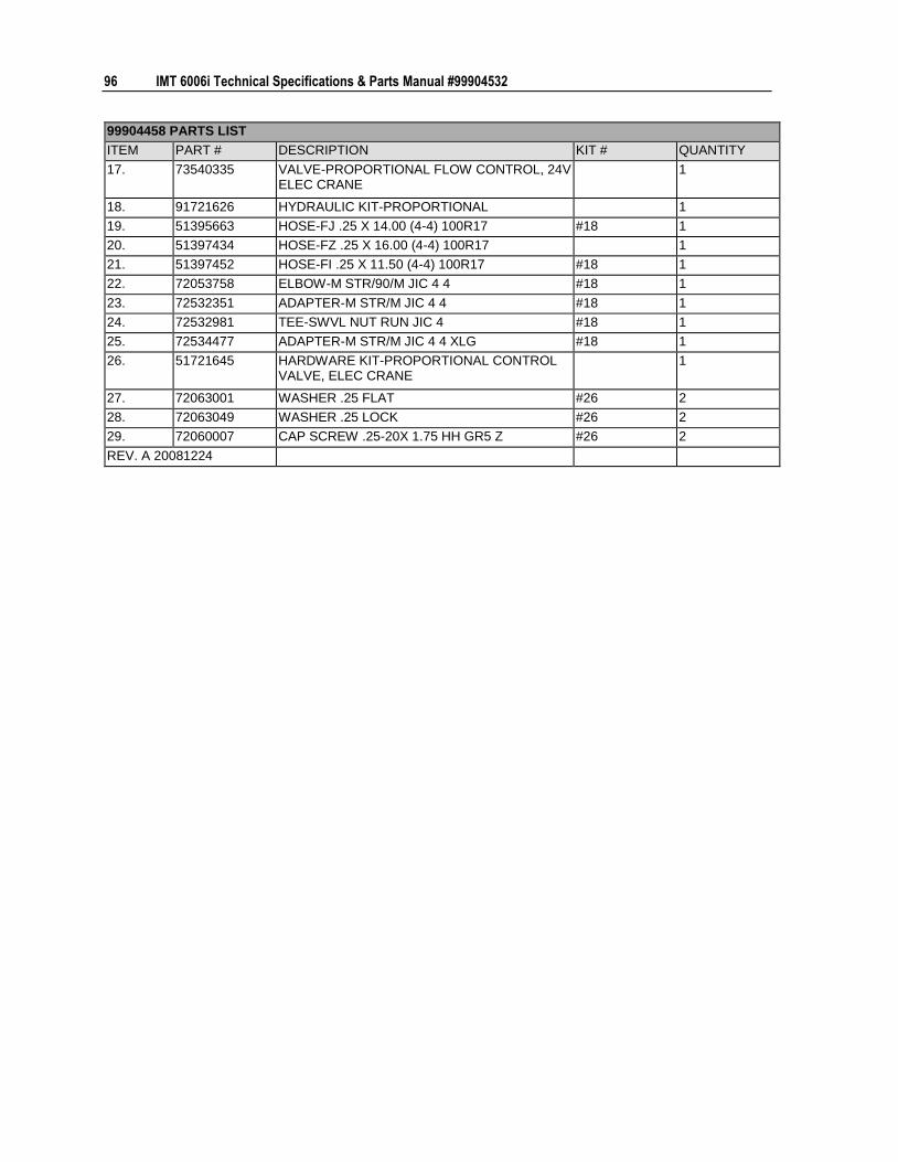
96 IMT 6006i Technical Specifications & Parts Manual #99904532
99904458 PARTS LIST
ITEM PART # DESCRIPTION KIT # QUANTITY
17. 73540335 VALVE-PROPORTIONAL FLOW CONTROL, 24V ELEC CRANE
1
18. 91721626 HYDRAULIC KIT-PROPORTIONAL 1
19. 51395663 HOSE-FJ .25 X 14.00 (4-4) 100R17 #18 1
20. 51397434 HOSE-FZ .25 X 16.00 (4-4) 100R17 1
21. 51397452 HOSE-FI .25 X 11.50 (4-4) 100R17 #18 1
22. 72053758 ELBOW-M STR/90/M JIC 4 4 #18 1
23. 72532351 ADAPTER-M STR/M JIC 4 4 #18 1
24. 72532981 TEE-SWVL NUT RUN JIC 4 #18 1
25. 72534477 ADAPTER-M STR/M JIC 4 4 XLG #18 1
26. 51721645 HARDWARE KIT-PROPORTIONAL CONTROL VALVE, ELEC CRANE
1
27. 72063001 WASHER .25 FLAT #26 2
28. 72063049 WASHER .25 LOCK #26 2
29. 72060007 CAP SCREW .25-20X 1.75 HH GR5 Z #26 2
REV. A 20081224

Chapter 4 Parts 97
6006i Decal Installation (95721549)
12
25
9
5
4
4
5
6,7,10
2831
30
11
2613
27
54
22
12
25
2614
27
DECAL PLACEMENT (IF NOT SHOWN ON CRANE)
ITEM # PLACEMENT
15,21,23, 24,28,29
AT OR NEAR REMOTE HANDLE STORAGE POINT
16 2 ON REAR OUTRIGGERS
19 AT OR NEAR DRIVELINE
18,20 ON ALL FOUR SIDES OF CARRIER VEHICLE
32 ON CRANE POWER CABLE CONNECTION AT VEHICLE BATTERY
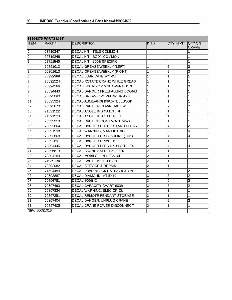
98 IMT 6006i Technical Specifications & Parts Manual #99904532
99904375 PARTS LIST
ITEM PART # DESCRIPTION KIT # QTY IN KIT QTY ON CRANE
1. 95719347 DECAL KIT - TELE COMMON 1
2. 95719348 DECAL KIT - BODY COMMON 1
3. 95721549 DECAL KIT - 6006i SPECIFIC 1
4. 70391612 DECAL-GREASE WEEKLY (LEFT) 1 9 3
5. 70391613 DECAL-GREASE WEEKLY (RIGHT) 1 6 3
6. 70392399 DECAL-LUBRICATE WORM 1 1 1
7. 70392524 DECAL-ROTATE CRANE WHILE GREAS 1 1 1
8. 70394166 DECAL-INSTR FOR MNL OPERATION 1 1 0
9. 70394443 DECAL-DANGER FREEFALLING BOOMS 1 1 1
10. 70395090 DECAL-GREASE WORM DR BRNGS 1 1 1
11. 70395324 DECAL-ASME/ANSI B30.5-TELESCOP 1 1 1
12. 70395670 DECAL-CAUTION DOWN HAUL WT 1 2 2
13. 71391522 DECAL-ANGLE INDICATOR RH 1 1 1
14. 71391523 DECAL-ANGLE INDICATOR LH 1 1 1
15. 70392213 DECAL-CAUTION DONT WASH/WAX 1 1 1
16. 70392864 DECAL-DANGER OUTRG STAND CLEAR 2 4 2
17. 70391598 DECAL-WARNING, MAN OUTRIG 2 2 0
18. 70392868 DECAL-DANGER CR LOADLINE (TRK) 2 4 4
19. 70392891 DECAL-DANGER DRIVELINE 2 1 1
20. 70394445 DECAL-DANGER ELEC HZD LG TELES 2 4 4
21. 70396613 DECAL-CRANE SAFETY & OPER 2 1 1
22. 70394189 DECAL-MOBILOIL RESERVOIR 2 1 1
23. 71039134 DECAL-CAUTION OIL LEVEL 2 1 1
24. 70392982 DECAL-SERVICE & REPAIR 2 1 1
25. 71394453 DECAL-LOAD BLOCK RATING 4.0TON 3 2 2
26. 70392887 DECAL-DIAMOND IMT 5X10 3 2 2
27. 70396781 DECAL-6006i ID 3 2 2
28. 70397493 DECAL-CAPACITY CHART 6006i 3 2 2
29. 70397334 DECAL-WARNING, ELEC CR OL 3 1 1
30. 70397351 DECAL-REMOTE PENDANT STORAGE 3 1 1
31. 70397404 DECAL-DANGER, UNPLUG CRANE 3 2 2
32. 70397405 DECAL-CRANE POWER DISCONNECT 3 1 1
NEW 20081015
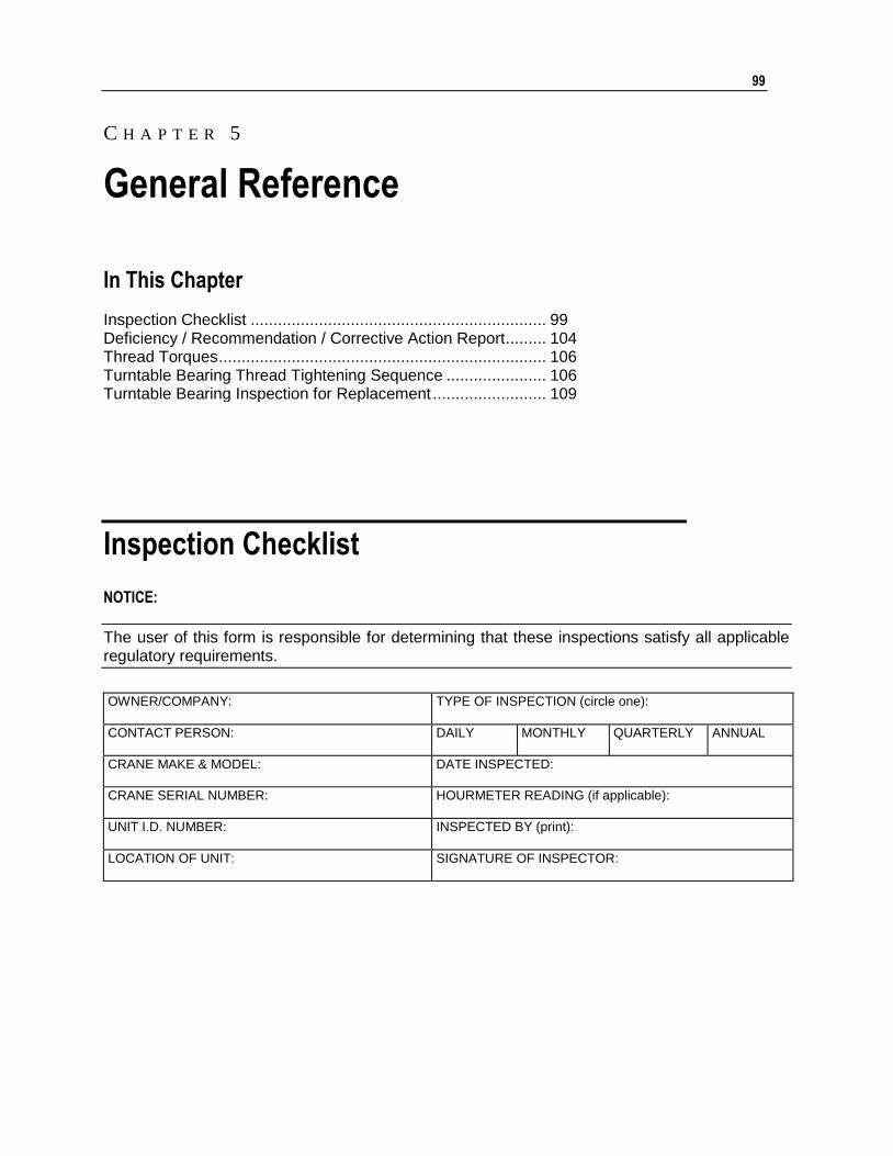
99
In This Chapter
Inspection Checklist ................................................................. 99 Deficiency / Recommendation / Corrective Action Report ......... 104 Thread Torques ........................................................................ 106 Turntable Bearing Thread Tightening Sequence ...................... 106 Turntable Bearing Inspection for Replacement ......................... 109
Inspection Checklist
NOTICE:
The user of this form is responsible for determining that these inspections satisfy all applicable regulatory requirements.
OWNER/COMPANY:
TYPE OF INSPECTION (circle one):
CONTACT PERSON: DAILY MONTHLY QUARTERLY ANNUAL
CRANE MAKE & MODEL: DATE INSPECTED:
CRANE SERIAL NUMBER: HOURMETER READING (if applicable):
UNIT I.D. NUMBER:
INSPECTED BY (print):
LOCATION OF UNIT: SIGNATURE OF INSPECTOR:
C H A P T E R 5
General Reference
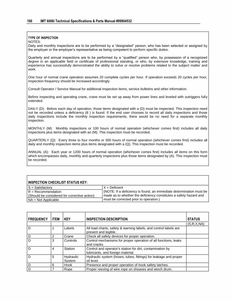
100 IMT 6006i Technical Specifications & Parts Manual #99904532
TYPE OF INSPECTION NOTES: Daily and monthly inspections are to be performed by a “designated” person, who has been selected or assigned by the employer or the employer’s representative as being competent to perform specific duties. Quarterly and annual inspections are to be performed by a “qualified” person who, by possession of a recognized degree in an applicable field or certificate of professional standing, or who, by extensive knowledge, training and experience has successfully demonstrated the ability to solve or resolve problems related to the subject matter and work. One hour of normal crane operation assumes 20 complete cycles per hour. If operation exceeds 20 cycles per hour, inspection frequency should be increased accordingly. Consult Operator / Service Manual for additional inspection items, service bulletins and other information. Before inspecting and operating crane, crane must be set up away from power lines and leveled with outriggers fully extended. DAILY (D): Before each day of operation, those items designated with a (D) must be inspected. This inspection need not be recorded unless a deficiency (8 ) is found. If the end user chooses to record all daily inspections and those daily inspections include the monthly inspection requirements, there would be no need for a separate monthly inspection. MONTHLY (M): Monthly inspections or 100 hours of normal operation (whichever comes first) includes all daily inspections plus items designated with an (M). This inspection must be recorded. QUARTERLY (Q): Every three to four months or 300 hours of normal operation (whichever comes first) includes all daily and monthly inspection items plus items designated with a (Q). This inspection must be recorded. ANNUAL (A): Each year or 1200 hours of normal operation (whichever comes first) includes all items on this form which encompasses daily, monthly and quarterly inspections plus those items designated by (A). This inspection must be recorded.
INSPECTION CHECKLIST STATUS KEY:
S = Satisfactory X = Deficient (NOTE: If a deficiency is found, an immediate determination must be made as to whether the deficiency constitutes a safety hazard and must be corrected prior to operation.)
R = Recommendation (Should be considered for corrective action)
NA = Not Applicable
FREQUENCY ITEM KEY INSPECTION DESCRIPTION STATUS
(S,R,X,NA)
D 1 Labels All load charts, safety & warning labels, and control labels are present and legible.
D 2 Crane Check all safety devices for proper operation.
D 3 Controls Control mechanisms for proper operation of all functions, leaks and cracks.
D 4 Station Control and operator's station for dirt, contamination by lubricants, and foreign material.
D 5 Hydraulic System
Hydraulic system (hoses, tubes, fittings) for leakage and proper oil level.
D 6 Hook Presence and proper operation of hook safety latches.
D 7 Rope Proper reeving of wire rope on sheaves and winch drum.

Chapter 5 General Reference 101
FREQUENCY ITEM KEY INSPECTION DESCRIPTION STATUS
(S,R,X,NA)
D 8 Pins Proper engagement of all connecting pins and pin retaining devices.
D 9 General Overall observation of crane for damaged or missing parts, cracked welds, and presence of safety covers.
D 10 Operation During operation, observe crane for abnormal performance, unusual wear (loose pins, wire rope damage, etc.). If observed, discontinue use and determine cause and severity of hazard.
D 11 Remote Ctrl Operate remote control devices to check for proper operation.
D 12 Electrical Operate all lights, alarms, etc. to check for proper operation.
D 13 Anti 2-Block Operate anti 2-block device to check for proper operation.
D 14 Other (Per customer requirements)
D 15 Other (Per customer requirements)
M 16 Daily All daily inspection items.
M 17 Cylinders Visual inspection of cylinders for leakage at rod, fittings, and welds. Damage to rod and case.
M 18 Valves Holding valves for proper operation.
M 19 Valves Control valves for leaks at fittings and between stations.
M 20 Valves Control valve linkages for wear, smoothness of operation, and tightness of fasteners.
M 21 General Bent, broken, or significantly rusted/corroded parts.
M 22 Electrical Electrical systems for presence of dirt, moisture, and frayed wires.
M 23 Structure All structural members for damage.
M 24 Welds All welds for breaks and cracks.
M 25 Pins All pins for proper installation and condition.
M 26 Hardware All bolts, fasteners and retaining rings for tightness, wear and corrosion.
M 27 Wear Pads Presence of wear pads.
M 28 Pump & Motor
Hydraulic pumps and motors for leakage at fittings, seals, and between sections.
M 29 PTO Transmission/PTO for leakage, abnormal vibration, and noise.
M 30 Hyd Fluid Quality of hydraulic fluid and presence of water.
M 31 Hyd Lines Hoses & tubes for leakage, abrasion damage, blistering, cracking, deterioration, fitting leakage, and secured properly.
M 32 Hook Load hook for abnormal throat distance, twist, wear, and cracks.
M 33 Rope Condition of load line.
M 34 Manual Presence of operator's manual with unit.
M 35 Other
Q 36 Daily All daily inspection items.
Q 37 Monthly All monthly inspection items.
Q 38 Extensions Condition of wear pads.
Q 39 Rotation Sys Rotation bearing for proper torque of all accessible mounting bolts.
Q 40 Hardware Base mounting bolts for proper torque.
Q 41 Structure All structural members for deformation, cracks and corrosion.
42 • Base
43 • Outrigger beams and legs
44 • Mast
45 • Inner Boom
46 • Outer Boom
47 • Extension(s)
48 • Jib boom

102 IMT 6006i Technical Specifications & Parts Manual #99904532
FREQUENCY ITEM KEY INSPECTION DESCRIPTION STATUS
(S,R,X,NA)
49 • Jib extension(s)
50 • Other
Q 51 Hardware Pins, bearing, shafts, gears, rollers, and locking devices for wear, cracks, corrosion and distortion.
52 • Rotation bearing(s)
53 • Inner boom pivot pin(s) and retainer(s)
54 • Outer boom pivot pin(s) and retainer(s)
55 • Inner boom cylinder pin(s) and retainer(s)
56 • Outer boom cylinder pin(s) and retainer(s)
57 • Extension cylinder pin(s) and retainer(s)
58 • Jib boom pin(s) and retainer(s)
59 • Jib cylinder pin(s) and retainer(s)
60 • Jib extension cylinder pin(s) and retainer(s)
61 • Boom tip attachment
62 • Other
Q 63 Hyd Lines Hoses, fittings and tubing for proper routing, leakage, blistering, deformation and excessive abrasion.
64 • Pressure line(s) from pump to control valve
65 • Return line(s) from control valve to reservoir
66 • Suction line(s) from reservoir to pump
67 • Pressure line(s) from control valve to each function
68 • Load holding valve pipe(s) and hose(s)
69 • Other
Q 70 Pumps, PTO's & Motors
Pumps, PTO's & motors for loose bolts/fasteners, leaks, noise, vibration, loss of performance, heating & excess pressure.
71 • Winch motor(s)
72 • Rotation motor(s)
73 • Other
Q 74 Valves Hydraulic valves for cracks, spool return to neutral, sticking spools, proper relief valve setting, relief valve failure.
75 • Main control valve
76 • Load holding valve(s)
77 • Outrigger or auxiliary control valve(s)
78 • Other valves (per customer requirements)
79 • Other (per customer requirements)
Q 80 Cylinders Hydraulic cylinders for drifting, rod seal leakage and leakage at welds. Rods for nicks, scores and dents. Case for damage. Case and rod ends for damage and abnormal wear.
81 • Outrigger cylinder(s)
82 • Inner boom cylinder(s)
83 • Outer boom cylinder(s)
84 • Extension cylinder(s)
85 • Rotation cylinder(s)
86 • Jib lift cylinder(s)
87 • Jib extension cylinder(s)
88 • Other (per customer requirements)
Q 89 Winch Winch, sheaves and drums for damage, abnormal wear, abrasions and other irregularities.
Q 90 Hyd Filters Hydraulic filters for replacement per maintenance schedule.
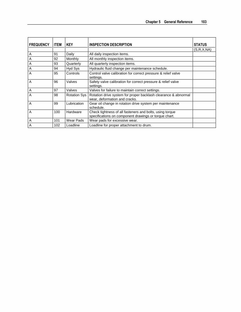
Chapter 5 General Reference 103
FREQUENCY ITEM KEY INSPECTION DESCRIPTION STATUS
(S,R,X,NA)
A 91 Daily All daily inspection items.
A 92 Monthly All monthly inspection items.
A 93 Quarterly All quarterly inspection items.
A 94 Hyd Sys Hydraulic fluid change per maintenance schedule.
A 95 Controls Control valve calibration for correct pressure & relief valve settings.
A 96 Valves Safety valve calibration for correct pressure & relief valve settings.
A 97 Valves Valves for failure to maintain correct settings.
A 98 Rotation Sys Rotation drive system for proper backlash clearance & abnormal wear, deformation and cracks.
A 99 Lubrication Gear oil change in rotation drive system per maintenance schedule.
A 100 Hardware Check tightness of all fasteners and bolts, using torque specifications on component drawings or torque chart.
A 101 Wear Pads Wear pads for excessive wear.
A 102 Loadline Loadline for proper attachment to drum.
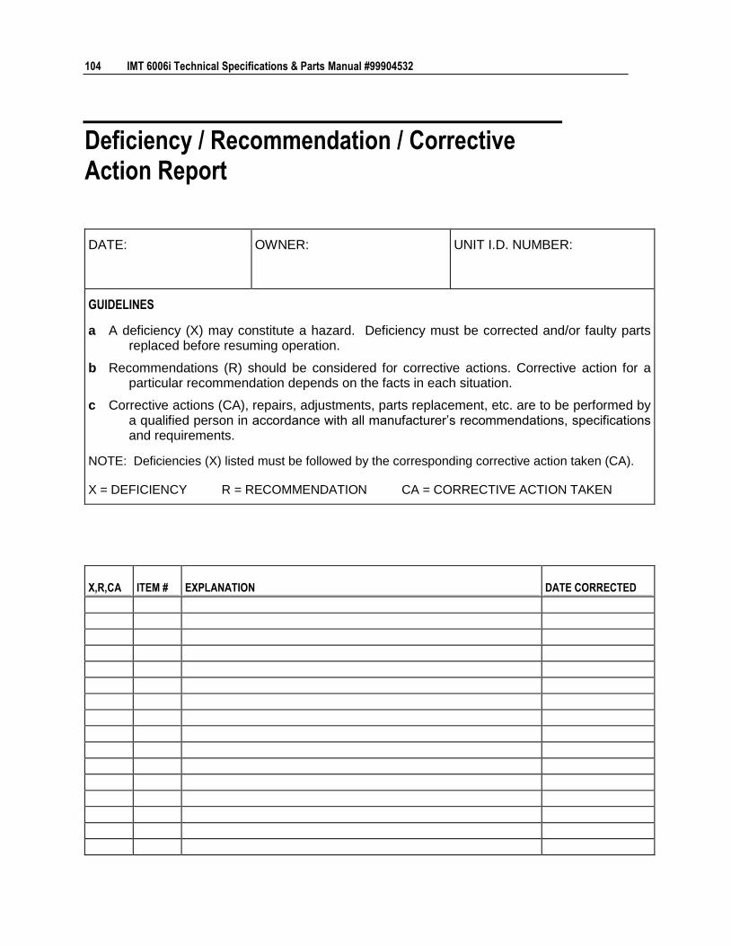
104 IMT 6006i Technical Specifications & Parts Manual #99904532
Deficiency / Recommendation / Corrective Action Report
DATE: OWNER: UNIT I.D. NUMBER:
GUIDELINES
a A deficiency (X) may constitute a hazard. Deficiency must be corrected and/or faulty parts replaced before resuming operation.
b Recommendations (R) should be considered for corrective actions. Corrective action for a particular recommendation depends on the facts in each situation.
c Corrective actions (CA), repairs, adjustments, parts replacement, etc. are to be performed by a qualified person in accordance with all manufacturer’s recommendations, specifications and requirements.
NOTE: Deficiencies (X) listed must be followed by the corresponding corrective action taken (CA).
X = DEFICIENCY R = RECOMMENDATION CA = CORRECTIVE ACTION TAKEN
X,R,CA ITEM # EXPLANATION DATE CORRECTED

Chapter 5 General Reference 105
X,R,CA ITEM # EXPLANATION DATE CORRECTED
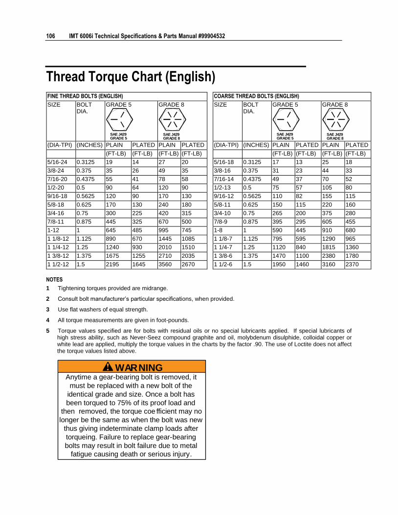
106 IMT 6006i Technical Specifications & Parts Manual #99904532
Thread Torque Chart (English)
FINE THREAD BOLTS (ENGLISH) COARSE THREAD BOLTS (ENGLISH)
SIZE BOLT DIA.
GRADE 5
SAE J429GRADE 5
GRADE 8
SAE J429GRADE 8
SIZE BOLT DIA.
GRADE 5
SAE J429GRADE 5
GRADE 8
SAE J429GRADE 8
(DIA-TPI) (INCHES) PLAIN PLATED PLAIN PLATED (DIA-TPI) (INCHES) PLAIN PLATED PLAIN PLATED
(FT-LB) (FT-LB) (FT-LB) (FT-LB) (FT-LB) (FT-LB) (FT-LB) (FT-LB)
5/16-24 0.3125 19 14 27 20 5/16-18 0.3125 17 13 25 18
3/8-24 0.375 35 26 49 35 3/8-16 0.375 31 23 44 33
7/16-20 0.4375 55 41 78 58 7/16-14 0.4375 49 37 70 52
1/2-20 0.5 90 64 120 90 1/2-13 0.5 75 57 105 80
9/16-18 0.5625 120 90 170 130 9/16-12 0.5625 110 82 155 115
5/8-18 0.625 170 130 240 180 5/8-11 0.625 150 115 220 160
3/4-16 0.75 300 225 420 315 3/4-10 0.75 265 200 375 280
7/8-11 0.875 445 325 670 500 7/8-9 0.875 395 295 605 455
1-12 1 645 485 995 745 1-8 1 590 445 910 680
1 1/8-12 1.125 890 670 1445 1085 1 1/8-7 1.125 795 595 1290 965
1 1/4-12 1.25 1240 930 2010 1510 1 1/4-7 1.25 1120 840 1815 1360
1 3/8-12 1.375 1675 1255 2710 2035 1 3/8-6 1.375 1470 1100 2380 1780
1 1/2-12 1.5 2195 1645 3560 2670 1 1/2-6 1.5 1950 1460 3160 2370
NOTES
1 Tightening torques provided are midrange.
2 Consult bolt manufacturer’s particular specifications, when provided.
3 Use flat washers of equal strength.
4 All torque measurements are given in foot-pounds.
5 Torque values specified are for bolts with residual oils or no special lubricants applied. If special lubricants of high stress ability, such as Never-Seez compound graphite and oil, molybdenum disulphide, colloidal copper or white lead are applied, multiply the torque values in the charts by the factor .90. The use of Loctite does not affect the torque values listed above.
WARNINGAnytime a gear-bearing bolt is removed, it
must be replaced with a new bolt of the
identical grade and size. Once a bolt has
been torqued to 75% of its proof load and
then removed, the torque coe fficient may no
longer be the same as when the bolt was new
thus giving indeterminate clamp loads after
torqueing. Failure to replace gear-bearing
bolts may result in bolt failure due to metal
fatigue causing death or serious injury.
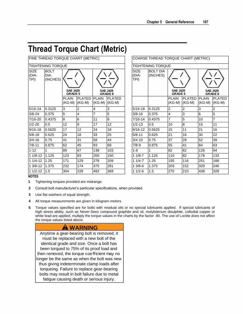
Chapter 5 General Reference 107
Thread Torque Chart (Metric) FINE THREAD TORQUE CHART (METRIC) COARSE THREAD TORQUE CHART (METRIC)
TIGHTENING TORQUE TIGHTENING TORQUE
SIZE (DIA-TPI)
BOLT DIA. (INCHES)
SAE J429GRADE 5
SAE J429GRADE 8
SIZE (DIA-TPI)
BOLT DIA (INCHES)
SAE J429GRADE 5
SAE J429GRADE 8
PLAIN (KG-M)
PLATED (KG-M)
PLAIN (KG-M)
PLATED (KG-M)
PLAIN (KG-M)
PLATED (KG-M)
PLAIN (KG-M)
PLATED (KG-M)
5/16-24 0.3125 3 2 4 3 5/16-18 0.3125 2 2 3 2
3/8-24 0.375 5 4 7 5 3/8-16 0.375 4 3 6 5
7/16-20 0.4375 8 6 11 8 7/16-14 0.4375 7 5 10 7
1/2-20 0.5 12 9 17 12 1/2-13 0.5 10 8 15 11
9/16-18 0.5625 17 12 24 18 9/16-12 0.5625 15 11 21 16
5/8-18 0.625 24 18 33 25 5/8-11 0.625 21 16 30 22
3/4-16 0.75 41 31 58 44 3/4-10 0.75 37 28 52 39
7/8-11 0.875 62 45 93 69 7/8-9 0.875 55 41 84 63
1-12 1 89 67 138 103 1-8 1 82 62 126 94
1 1/8-12 1.125 123 93 200 150 1 1/8-7 1.125 110 82 178 133
1 1/4-12 1.25 171 129 278 209 1 1/4-7 1.25 155 116 251 188
1 3/8-12 1.375 232 174 375 281 1 3/8-6 1.375 203 152 329 246
1 1/2-12 1.5 304 228 492 369 1 1/2-6 1.5 270 210 438 328
NOTES
1 Tightening torques provided are midrange.
2 Consult bolt manufacturer’s particular specifications, when provided.
3 Use flat washers of equal strength.
4 All torque measurements are given in kilogram-meters.
5 Torque values specified are for bolts with residual oils or no special lubricants applied. If special lubricants of high stress ability, such as Never-Seez compound graphite and oil, molybdenum disulphite, collodial copper or white lead are applied, multiply the torque values in the charts by the factor .90. The use of Loctite does not affect the torque values listed above.
WARNINGAnytime a gear-bearing bolt is removed, it
must be replaced with a new bolt of the
identical grade and size. Once a bolt has
been torqued to 75% of its proof load and
then removed, the torque coe ff icient may no
longer be the same as when the bolt was new
thus giving indeterminate clamp loads after
torqueing. Failure to replace gear-bearing
bolts may result in bolt failure due to metal
fatigue causing death or serious injury.
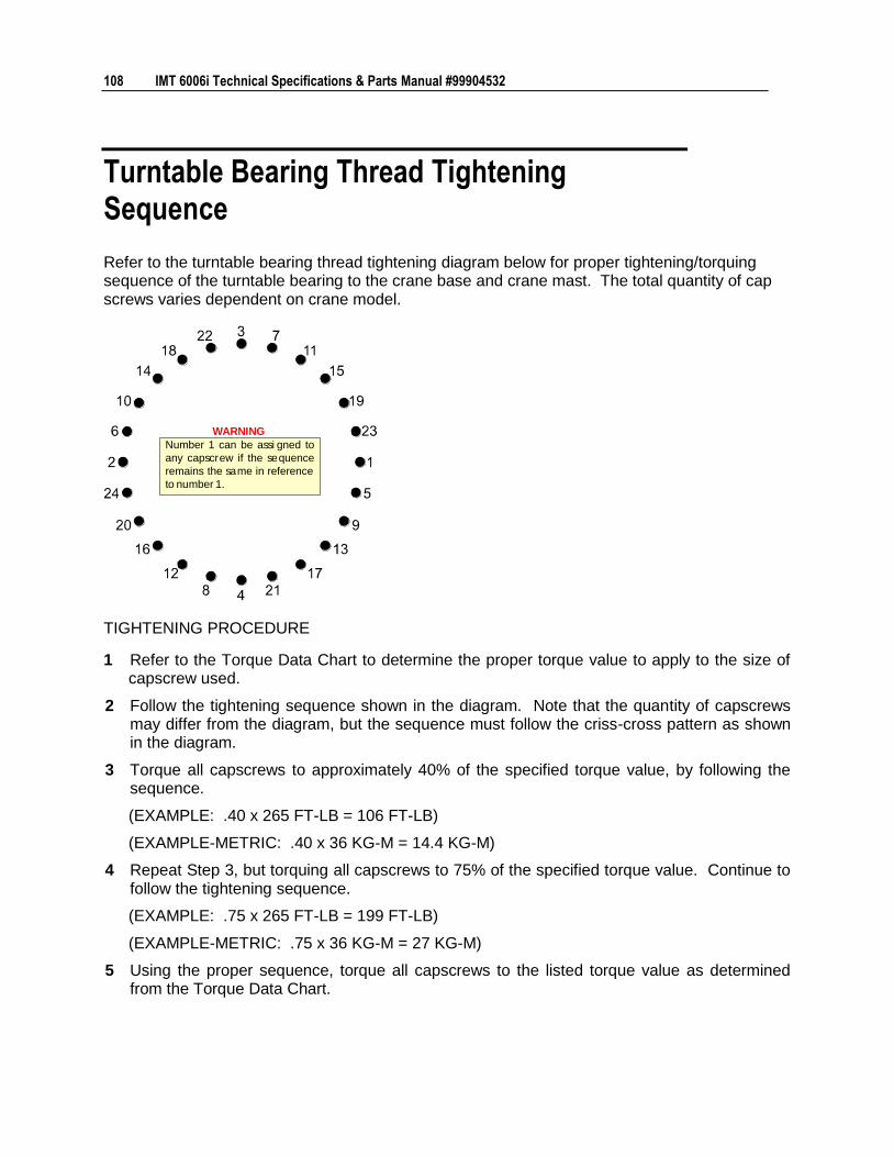
108 IMT 6006i Technical Specifications & Parts Manual #99904532
Turntable Bearing Thread Tightening Sequence
Refer to the turntable bearing thread tightening diagram below for proper tightening/torquing sequence of the turntable bearing to the crane base and crane mast. The total quantity of cap screws varies dependent on crane model.
Number 1 can be assi gned to
any capscrew if the sequence
remains the same in reference
to number 1.
WARNING
TIGHTENING PROCEDURE
1 Refer to the Torque Data Chart to determine the proper torque value to apply to the size of capscrew used.
2 Follow the tightening sequence shown in the diagram. Note that the quantity of capscrews may differ from the diagram, but the sequence must follow the criss-cross pattern as shown in the diagram.
3 Torque all capscrews to approximately 40% of the specified torque value, by following the sequence.
(EXAMPLE: .40 x 265 FT-LB = 106 FT-LB)
(EXAMPLE-METRIC: .40 x 36 KG-M = 14.4 KG-M)
4 Repeat Step 3, but torquing all capscrews to 75% of the specified torque value. Continue to follow the tightening sequence.
(EXAMPLE: .75 x 265 FT-LB = 199 FT-LB)
(EXAMPLE-METRIC: .75 x 36 KG-M = 27 KG-M)
5 Using the proper sequence, torque all capscrews to the listed torque value as determined from the Torque Data Chart.
Chapter 5 General Reference 109
Turntable Bearing Inspection for Replacement
Before a bearing is removed from a crane for inspection, one of the following conditions should be evident:
1 Metal particles present in the bearing lubricant.
2 Increased drive power required to rotate the crane.
3 Noise emitting from the bearing during crane rotation.
4 Rough crane rotation.
5 Uneven or excessive wear between the pinion gear and turntable gear.
If none of the listed conditions exists, the bearing is functioning properly and need not be replaced. But, if one or more of the above conditions exists, inspection may be required. Limits are measured in “TILT” which is dependent on the internal clearances of the bearing. TILT is the most practical determination of a bearings internal clearance once mounted on a crane.
Periodic readings indicating a steady increase in TILT may be an indicator of bearing wear. Note that a bearing found to have no raceway cracks or other structural irregularities should be reassembled and returned to service.