Embed Size (px)
Citation preview

iMX6 OpenRexSingle Board Computer
Designed by FEDEVEL Academy
Datasheet
Date Revision Changes
November 15, 2016 1.0 Initial Release
April 6, 2017 1.1 PCIe micro SIM socket updated
iMX6 OpenRex SBC Datasheet
Table of Contents
1. Introduction.................................................................................................................................................... 4
1.1 General........................................................................................................................................................ 41.2 Software....................................................................................................................................................... 41.3 Booting Options........................................................................................................................................... 41.4 Hardware – Block Diagram ......................................................................................................................... 51.5 Features....................................................................................................................................................... 61.6 Reference Documents................................................................................................................................. 7
2. Functional Processor Description............................................................................................................7
2.1 Features....................................................................................................................................................... 72.2 i.MX6 Series Applications Processors Block Diagram.................................................................................8
3. Features Description................................................................................................................................... 9
3.1 User Interfaces............................................................................................................................................ 93.2 Board Layout – Connectors, Jumpers, LEDs, Buttons and Peripheral selection resistors...........................93.3 Connectors, Jumpers, LEDs, Buttons and Resistors list ...........................................................................12
4. Connector Description.............................................................................................................................. 13
4.1 Pinout Description...................................................................................................................................... 134.1.1 J1 – Arduino Like Header............................................................................................................134.1.2 J2 – Raspberry PI Compatible Connector...................................................................................144.1.3 J3 – UART Serial Console...........................................................................................................154.1.4 J4 – USB 2x Host Stacked..........................................................................................................154.1.5 J5 – HDMI Output Connector......................................................................................................164.1.6 J6 – Ethernet Connector..............................................................................................................174.1.7 J7 – CSI Camera Input or RGB Display Output...........................................................................184.1.8 J8 – SATA Connector.................................................................................................................. 194.1.9 J9 – Power Input Connector........................................................................................................204.1.10 J10 – Touchscreen Connector...................................................................................................204.1.11 J11 – USB OTG......................................................................................................................... 204.1.12 J12 – Raspberry Pi Camera or LVDS........................................................................................214.1.13 J13 – microSDTM Slot.................................................................................................................214.1.14 J14 – Audio Jack....................................................................................................................... 224.1.15 J15 – PCIe Mini Card 1 Slot......................................................................................................234.1.16 J17 – PCIe Micro SIM Socket ...................................................................................................24
5. Jumper, Buttons, LEDs and Resistors Description...........................................................................25
5.1 Jumper Pinout Description.........................................................................................................................255.1.1 JP1 – Power Input Selection........................................................................................................255.1.2 JP2 – Boot Mode Selection.........................................................................................................25
5.2 Buttons and LEDs Description................................................................................................................... 265.2.1 SW1 – Reset/Power button.........................................................................................................265.2.2 SW2 – User/Android Button (Home/Wake Up)............................................................................265.2.3 SW3 – User/Android Button (Back/Volume-)...............................................................................265.2.4 SW4 – User/Android Button (Recent/Volume+)...........................................................................265.2.5 D1, D2, D3, D33 – CPU/MCU User LED (RED)..........................................................................27

iMX6 OpenRex SBC Datasheet
5.2.6 D5, D6, D7, D34 – CPU User LED (RED)...................................................................................275.2.7 D11, D25, D26 – MPCIE LEDs (GREEN)....................................................................................275.2.8 D12 – USB LED (ORANGE)........................................................................................................275.2.9 D14 – microSD LED (ORANGE)..................................................................................................285.2.10 D21 – CPU User LED (ORANGE).............................................................................................285.2.11 D22 – Power OK LED (GREEN)................................................................................................285.2.12 D24 – MCU User LED (ORANGE).............................................................................................28
5.3 Resistors Selection Description................................................................................................................. 29
5.3.1 PSR1 USB0 Routing....................................................................................................................295.3.2 PSR2 USB1 Routing....................................................................................................................295.3.3 PSR3 USB1 to Header / MCU Routing........................................................................................305.3.4 PSR4 CSI / LVDS Routing...........................................................................................................30
6. Technical Specifications........................................................................................................................... 31
6.1 Input Voltage.............................................................................................................................................. 316.2 Mechanical................................................................................................................................................. 326.3 Temperature Range................................................................................................................................... 336.4 CE compliance of Voipac products............................................................................................................336.5 RoHS and WEEE Compliance...................................................................................................................33
Warranty:........................................................................................................................................................... 34
Disclaimer:........................................................................................................................................................ 34
Trademark Acknowledgment:...................................................................................................................... 34
VOIPAC TECHNOLOGIES s.r.o., M.R. Štefánika 6670/19, 911 01 Trenčín, Slovakia, www.voipac.com- 3 -

iMX6 OpenRex SBC Datasheet
1. Introduction
1.1 General
iMX6 OpenRex is completely open source Single Board Computer (SBC) poweredby NXP (Freescale) i.MX6 ARM® Cortex® A9 multicore CPU. The board further features NXPLPC1345 ARM® Cortex® M3 microcontroller, multiple camera inputs, and a series of built-insensors including compass & accelerometer, gyroscope, humidity sensor, and temperaturesensor making it ideal choice for industrial as well as home automation applications.
It was designed also for playing, learning and hacking thus includes Raspberry Pi & Arduinolike GPIO headers, and is available with complete Altium Designer projectdocumentation including schematics and PCB layout source files, as well asmanufacturing documentation.
1.2 Software
Voipac fully supports Linux operating system with drivers for all basic interfaces.Custom additional drivers for specific applications can be developed upon request.
Operating system Description
Yocto Yocto Project Linux distribution preinstalled on microSDHC card
Android TBA
1.3 Booting Options
iMX6 OpenRex Single Board Computer in standard configuration comes with e-Fuses set for boot from SPI Flash. There are more booting posibilities:
Booting Option Description
SD Card A standard configuration board is set for this boot option (SD2) in u-boot through SPI Flash.
I2C Supported possibilty for EEPROM booting (I2C1).
SPI Default booting from SPI Flash on OpenRex Single Board Computer (SPI3).
SPI Possible SPI1 booting. Signals are on connector J2 (RPi Header).
SATA Available only with i.MX6 QuadPlus / Quad / Dual processors.
The SBC supports following booting options: - Boot From e-Fuses : Standard mode - Serial Downloader : USB mode
Internal Boot mode is not supported.
VOIPAC TECHNOLOGIES s.r.o., M.R. Štefánika 6670/19, 911 01 Trenčín, Slovakia, www.voipac.com- 4 -

1.4 Hardware – Block Diagram

iMX6 OpenRex SBC Datasheet
1.5 FeaturesFEATURES ULTRA
CONFIGURATIONMAX
CONFIGURATIONBASIC
CONFIGURATION
NXP (Freescale) i.MX6 ARM® Cortex® A9 QuadPlus CPU, 1GHz Quad CPU, 1GHz Solo CPU, 1GHz
NXP microcontroller LPC1345FHN33 ARM® Cortex® M3, 72MHz ✔ ✔ ✔
DDR3-1066 SDRAM 4GB (533MHz) 2GB (533MHz) 512MB (400MHz)
1x 10/100/1000 Mbps Ethernet ✔ ✔ ✔
1x HDMI Output (up to QXGA 2048×1536) ✔ ✔ ✔
1x Parallel CSI Camera input or RGB Parallel Display output ✔ ✔ ✔
1x Differential Camera Input (Compatible with Raspberry Pi) or LVDS display output) ✔ ✔ ✔
1x SATA ✔ ✔ ✘
1x micro SD ✔ ✔ ✔
PCIE mini slot + micro SIM (can be used for WiFi or Wireless modem) ✔ ✔ ✔
1x USB OTG Micro ✔ ✔ ✔
2x USB ✔ ✔ ✔
1x CAN transceiver ✔ ✔ ✔
1x Compass + Accelerometer ✔ ✔ ✔
1x Gyroscope ✔ ✔ ✔
1x Humidity sensor ✔ ✔ ✔
1x Temperature sensor ✔ ✔ ✔
1x Audio (Headphones output, Microphone input) ✔ ✔ ✔
1x Touchscreen connector (Touchscreen through LPC1345 / Optional 4x Analog input) ✔ ✔ ✔
1x EEPROM 16Kbit I2C 16Kbit I2C 2Kbit I2C
1x 32Mbit SPI FLASH ✔ ✔ ✔
1x IR Receiver ✔ ✔ ✔
1x Arduino type header (Default)
4x Analog input3x GPIO1x I2C1x CAN1x USB
✔ ✔ ✔
1x Raspberry Pi type header (Default)
2x I2C2x UART1x CAN TX/RX2x SPI3x GPIO/PWM
✔ ✔ ✔
1x UART Debug console (FTDI compatible) ✔ ✔ ✔
8+2 USER LED ✔ ✔ ✔
Power LED, SD Card LED, USB HUB LED ✔ ✔ ✔
1x Reset button, 3x User button (e.g. Home, Volume Up, Volume Down) ✔ ✔ ✔
Size: 70 x 95 mm (2.75 x 3.75 inch)
Input power: 5V DC (through Power Jack or USB micro)
8GB microSDHC Class 4 memory card
1x Aluminum 14x14x14mm heatsink
0°C to +70°C commercial temperature range
Yocto Project Linux distribution preinstalled on microSDHC card
Lead free / RoHS compliant
VOIPAC TECHNOLOGIES s.r.o., M.R. Štefánika 6670/19, 911 01 Trenčín, Slovakia, www.voipac.com- 6 -
iMX6 OpenRex SBC Datasheet
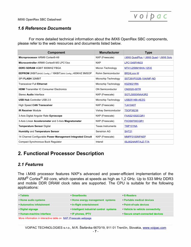
1.6 Reference Documents
For more detailed technical information about the iMX6 OpenRex SBC components, please refer to the web resources and documents listed below.
Component Manufacturer Type
Microprocessor ARM® Cortex®-A9 NXP (Freescale) i.MX6 QuadPlus / i.MX6 Quad / i.MX6 Solo
Microcontroller ARM® Cortex®-M3 LPC13xx NXP LPC1345FHN33
DDR3 SDRAM 4GBIT 800MHZ FBGA Micron Technology MT41J256M16HA-125:E
EEPROM 2KBIT(BASIC Config.) / 16KBIT(MAX Config.) 400KHZ 8MSOP Rohm Semiconductor BR24Lxxx-W
SPI FLASH 32MBIT Microchip Technology SST26VF032B-104I/MF-ND
Transceiver Full Ethernet Microchip Technology KSZ9021RN
HDMI Transmitter IC Consumer Electronics ON Semiconductor CM2020-00TR
Stereo Audio Interface NXP (Freescale) SGTL5000XNAA3R2
USB Hub Controller USB 2.0 Microchip Technology USB2514BI-AEZG
High Speed CAN Transceiver NXP (Freescale) TJA1040T
IR Receiver Module Vishay Semiconductor TSOP38238
3-Axis Digital Angular Rate Gyroscope NXP (Freescale) FXAS21002CQR1
3-Axis Linear Accelerometer and 3-Axis Magnetometer NXP (Freescale) FXOS8700CQR1
Temperature Sensor Digital Texas Instruments TMP101NA
Humidity and Temperature Sensor Sensirion AG SHT21
14 Channel Configurable Power Management Integrated Circuit NXP (Freescale) MMPF0100NPAEP
Compact Synchronous Buck Regulator Intersil ISL8024AIRTAJZ-T7A
2. Functional Processor Description
2.1 Features
The i.MX6 processor features NXP’s advanced and power-efficient implementation of theARM® Cortex® A9 core, which operates at speeds as high as 1,2 GHz. Up to 533 MHz DDR3and mobile DDR DRAM clock rates are supported. The CPU is suitable for the followingapplications:
• Tablets • Smartbooks • E-Readers
• Home audio systems • Home energy management systems • Portable medical devices
• Automotive infotainment • In-flight entertainment • Point-of-sale devices
• Digital signage • Intelligent industrial control systems • Vehicle to vehicle connectivity
• Human-machine interface • IP phones, IPTV • Secure smart-connected devices
More information in interactive table on NXP /Freescale webpage
VOIPAC TECHNOLOGIES s.r.o., M.R. Štefánika 6670/19, 911 01 Trenčín, Slovakia, www.voipac.com- 7 -

iMX6 OpenRex SBC Datasheet
2.2 i.MX6 Series Applications Processors Block Diagram
Available on certain product families. More information in interactive table on NXP/Freescale ’s webpage
VOIPAC TECHNOLOGIES s.r.o., M.R. Štefánika 6670/19, 911 01 Trenčín, Slovakia, www.voipac.com- 8 -

iMX6 OpenRex SBC Datasheet
i.MX6 Quad i.MX6 QuadPlus
Quad ARM® Cortex®-A9 up to 1.2 GHz Quad ARM® Cortex®-A9 up to 1.2 GHz
• 1 MB L2 cache, NEON, VFPvd16 TrustZone • 3D graphics with four shaders• Two 2D graphics engines• 64-bit DDR3 and 2-channel 32-bit LPDDR2 at 533 MHz• Gigabit Ethernet MAC• Integrated SATA-II• HDMIv1.4 controller plus PHY• LVDS controller plus PHY• PCIe controller plus PHY• MLB and FlexCAN controllers
• 1 MB L2 cache, NEON, VFPvd16 TrustZone • Enhanced 3D graphics with four shaders• Enhanced Two 2D graphics engines• Prefetch & Resolve Engine• Optimized 64-bit DDR3 and 2-channel 32-bit LPDDR2 at 533 MHz• Gigabit Ethernet MAC• Integrated SATA-II• HDMIv1.4 controller plus PHY• LVDS controller plus PHY• PCIe controller plus PHY• MLB and FlexCAN controllers
↓↑ Red indicates change from table to the left
i.MX6 Solo i.MX6 Dual
Single ARM® Cortex®-A9 up to 1.0 GHz Dual ARM® Cortex®-A9 up to 1.2 GHz
• 512 KB L2 cache, NEON, VFPvd16 TrustZone • 3D graphics with one shader• 2D graphics• 32-bit DDR3 and LPDDR2 at 400 MHz• Gigabit Ethernet MAC • Integrated EPD controller• HDMIv1.4 controller plus PHY• LVDS controller plus PHY• PCIe controller plus PHY• MLB and FlexCAN controllers
• 1 MB L2 cache, NEON, VFPvd16 TrustZone • 3D graphics with four shaders• Two 2D graphics engines• 64-bit DDR3 and 2-channel 32-bit LPDDR2 at 533 MHz• Gigabit Ethernet MAC• Integrated SATA-II• HDMIv1.4 controller plus PHY• LVDS controller plus PHY• PCIe controller plus PHY• MLB and FlexCAN controllers
3. Features Description
3.1 User Interfaces
The following user interfaces are available on the Voipac iMX6 OpenRex SBC.
Interface Description
HDMI HDMI Output with Audio
USB 1x USB OTG, 2x USB, 1x USB on Header, 1x USB on Mini PCIe Slot
PCIE Mini Card Socket (PCIE & USB)
Power Input Power Jack or USB Micro Connector
Headers 4x UART, 2x SPI, 1x CAN (Differential), 3x I2C, 3x PWM, 8x GPIO, 4x Analog Inputs, Power Output +3V3 and +5V
3.2 Board Layout – Connectors, Jumpers, LEDs, Buttons and Peripheral selection resistors
The top and bottom component placement on the next page shows interfaces layout of the iMX6 OpenRex SBC. All useful interfaces are shown in assembly top and bottom drawings and sumarized in subsection 3.3.
VOIPAC TECHNOLOGIES s.r.o., M.R. Štefánika 6670/19, 911 01 Trenčín, Slovakia, www.voipac.com- 9 -

iMX6 OpenRex SBC Datasheet
TOP SIDE
VOIPAC TECHNOLOGIES s.r.o., M.R. Štefánika 6670/19, 911 01 Trenčín, Slovakia, www.voipac.com- 10 -

iMX6 OpenRex SBC Datasheet
BOTTOM SIDE
VOIPAC TECHNOLOGIES s.r.o., M.R. Štefánika 6670/19, 911 01 Trenčín, Slovakia, www.voipac.com- 11 -

iMX6 OpenRex SBC Datasheet
3.3 Connectors, Jumpers, LEDs, Buttons and Resistors list
CONNECTORS BUTTONS
Ref.Num. Description Page Ref.Num. Description Page
J1 Arduino Like Header 13 SW1 Reset /Power Button 26
J2 Raspberry Pi Compatible Connector 14 SW2 User/Android Button (Home/Wake Up) 26
J3 UART Serial Console 15 SW3 User/Android Button (Back/Volume-) 26
J4 USB 2x Host Stacked 15 SW4 User/Android Button (Recent/Volume+) 26
J5 HDMI Output Connector 16
J6 1G Ethernet Connector RJ-45 17 LEDSJ7 CSI Camera Input or RGB Display Output 18 D1 CPU/MCU User LED 27
J8 SATA Connector 19 D2 CPU/MCU User LED 27
J9 Power Jack 20 D3 CPU/MCU User LED 27
J10 Touchscreen Connector 20 D5 CPU User LED 27
J11 USB OTG 20 D6 CPU User LED 27
J12 Raspberry Pi Camera or LVDS 21 D7 CPU User LED 27
J13 Micro SD Slot 21 D11 MPCIE LED 27
J14 Audio Jack 22 D12 USB Hub LED 27
J15 PCIe Mini Card Slot 23 D14 microSD LED 28
J16 PCIe Mini Card Latch D21 CPU User LED 28
J17 PCIe Micro SIM Socket 24 D22 Power OK LED 28
D24 MCU User LED 28
PERIPHERAL SELECTIONS RESISTORS D25 MPCIE LED 27
Ref.Num. Description Page D26 MPCIE LED 27
PSR1 USB0 Routing 29 D33 CPU/MCU User LED 27
PSR2 USB1 Routing 29 D34 CPU User LED 27
PSR3 USB1 to Header / MCU Routing 30
PSR4 CSI/LVDS Routing 30 JUMPERSRef.Num. Description Page
JP1 Power Input Selection 25
JP2 Boot Mode selection 25
VOIPAC TECHNOLOGIES s.r.o., M.R. Štefánika 6670/19, 911 01 Trenčín, Slovakia, www.voipac.com- 12 -

iMX6 OpenRex SBC Datasheet
4. Connector Description
This chapter describes the connectors of the iMX6 OpenRex SBC. Some connectorshave dedicated functionality, but some like TFT can be used also for other purposes, likegeneral purpose IO (GPIO) or general expansion bus. Described functions are default.
4.1 Pinout Description
4.1.1 J1 – Arduino Like Header (CONN RCPT 40POS .100" GOLD)
Description: 20 Position Receptacle Connector 0.100" (2.54mm) Through Hole Gold.The Connector is accesible from both sides. More functions are supported.(See Schematics, page 24)
Manufacturer: Samtec Inc.Connector: ESQ-120-14-G-S
PIN Signal Name Type Description
1 +VIN_5V PO
2 USB_HDR_N I/O
3 USB_HDR_P I/O
4 GND G
5 I2C1_SDA I/O
6 I2C1_SCL I/O
7 +3V3_HDR PO
8 CAN_N I/O
9 CAN_P I/O
10 GND G
11 CPU_GPIO0 I/O
12 CPU_GPIO1 I/O
13 CPU_GPIO2 I/O
14 RSTOUTn O
15 RST_BTN_HDR I
16 GND G
17 ANALOG_IN_0 I
18 ANALOG_IN_1 I
19 ANALOG_IN_2 I
20 ANALOG_IN_3 I
VOIPAC TECHNOLOGIES s.r.o., M.R. Štefánika 6670/19, 911 01 Trenčín, Slovakia, www.voipac.com- 13 -

iMX6 OpenRex SBC Datasheet
4.1.2 J2 – Raspberry PI Compatible Connector (CONN RCPT 40POS .100" DUAL GOLD)
Description: 40 Position Receptacle Connector 0.100" (2.54mm) Through Hole Gold.The Connector is accesible from both sides. More functions are supported.(See Schematics, page 24)
Manufacturer: Samtec Inc.Connector: ESQ-120-14-G-D
Description Type Signal Name PIN PIN Signal Name Type Description
PO +3V3_HDR 1 2 +VIN_5V PO
I/O I2C3_SDA 3 4 +VIN_5V PO
O I2C3_SCL 5 6 GND G
I/O GPIO_OR_CLK 7 8 UART3_TXD O
G GND 9 10 UART3_RXD I
O UART3_RTS 11 12 UART_TXD O
I UART4_RXD 13 14 GND G
O FLEXCAN2_TX 15 16 FLEXCAN2_RX I
PO +3V3_HDR 17 18 UART5_RXD I
O CSPI1_MOSI 19 20 GND G
I CSPI1_MISO 21 22 UART5_TXD O
O CSPI1_CLK 23 24 CSPI1_CS0 O
G GND 25 26 CSPI1_CS1 O
I/O I2C2_SDA 27 28 I2C2_SCL O
I/O GPIO_OR_PWM_1 29 30 GND G
I/O GPIO_OR_PWM_2 31 32 GPIO_OR_PWM_3 I/O
I/O GPIO_OR_PWM_4 33 34 GND G
O CSPI2_CS0 35 36 UART3_CTS I
O CSPI2_MOSI 37 38 CSPI2_CLK O
G GND 39 40 CSPI2_MISO I
VOIPAC TECHNOLOGIES s.r.o., M.R. Štefánika 6670/19, 911 01 Trenčín, Slovakia, www.voipac.com- 14 -

iMX6 OpenRex SBC Datasheet
4.1.3 J3 – UART Serial Console (CONN HEADER 6POS .100 STR 15AU)
Description: 6 Positions Header, Unshrouded Connector 0.100" (2.54mm) Through Hole Gold or Gold, GXT™.Serial console header is designed to be used with FTDI TTL-232R-3V3 TTL to USB Serial Converter.
Manufacturer: Amphenol FCIConnector: 68001-206HLF
PIN Signal Name Type Description
1 GND G
2 UART1_RTS_FTDI O
3 +5V_FTDI PI
4 UART1_RXD_FTDI I
5 UART1_TXD_FTDI O
6 UART1_CTS_FTDI I
4.1.4 J4 – USB 2x Host Stacked (CONN RCPT R/A 4OVER4POS GOLD PCB)
Description: USB - A, Stacked USB 2.0 Receptacle Connector 8 Position Through Hole, Right Angle,Horizontal.
Manufacturer: TE Connectivity AMP Connectors Connector: 5787617-1
Description Type PIN Name PIN PIN PIN Name Type Description
+5V_USB_BOT PO VBUS1 1 5 VBUS2 PO +5V_USB_TOP
USB_BOT_L_N I/O D1- 2 6 D2- I/O USB_TOP_L_N
USB_BOT_L_P I/O D1+ 3 7 D2+ I/O USB_TOP_L_P
GND G GND1 4 8 GND2 G GND
VOIPAC TECHNOLOGIES s.r.o., M.R. Štefánika 6670/19, 911 01 Trenčín, Slovakia, www.voipac.com- 15 -
iMX6 OpenRex SBC Datasheet
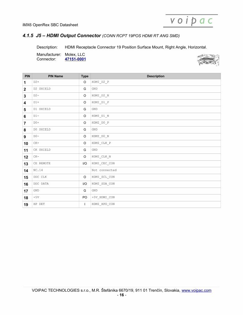
4.1.5 J5 – HDMI Output Connector (CONN RCPT 19POS HDMI RT ANG SMD)
Description: HDMI Receptacle Connector 19 Position Surface Mount, Right Angle, Horizontal.
Manufacturer: Molex, LLCConnector: 47151-0001
PIN PIN Name Type Description
1 D2+ O HDMI_D2_P
2 D2 SHIELD G GND
3 D2- O HDMI_D2_N
4 D1+ O HDMI_D1_P
5 D1 SHIELD G GND
6 D1- O HDMI_D1_N
7 D0+ O HDMI_D0_P
8 D0 SHIELD G GND
9 D0- O HDMI_D0_N
10 CK+ O HDMI_CLK_P
11 CK SHIELD G GND
12 CK- O HDMI_CLK_N
13 CE REMOTE I/O HDMI_CEC_CON
14 NC.14 Not connected
15 DDC CLK O HDMI_SCL_CON
16 DDC DATA I/O HDMI_SDA_CON
17 GND G GND
18 +5V PO +5V_HDMI_CON
19 HP DET I HDMI_HPD_CON
VOIPAC TECHNOLOGIES s.r.o., M.R. Štefánika 6670/19, 911 01 Trenčín, Slovakia, www.voipac.com- 16 -

iMX6 OpenRex SBC Datasheet
4.1.6 J6 – Ethernet Connector (CONN MAGJACK 1PORT SHLD 1000BT )
Description: 1 Port RJ45 Magjack Connector Through Hole 10/100/1000 Base-T, AutoMDIX.
Manufacturer: Bel Fuse Inc.Connector: L829-1J1T-43
PIN PIN Name Type Description Link / Activity State of Yellow LED State of Green LED
1 TRCT3 Link off OFF OFF
2 TRD3- I/O TRD2_N 1000 Link / No activity ON OFF
3 TRD3+ I/O TRD2_P 1000 Link / Activity Blinking OFF
4 TRD2+ I/O TRD1_P 100 Link / No Activity OFF ON
5 TRD2- I/O TRD1_N 100 Link / Activity OFF Blinking
6 TRCT2 10 Link / No Activity ON ON
7 TRCT4 10 Link / Activity Blinking Blinking
8 TRD4+ I/O TRD3_P
9 TRD4- I/O TRD3_N
10 TRD1- I/O TRD0_N
11 TRD1+ O TRD0_P
12 TRCT1
13 Y_CATODE O ENET_LED_LINK
14 Y_ANODE +3V3
15 O_CATODE NC ENET_LED_RX
16 COM_ANODE G +3V3
17 G_CATODE O ENET_LED_RX
18 SHIELD1 G GND
19 SHIELD2 G GND
VOIPAC TECHNOLOGIES s.r.o., M.R. Štefánika 6670/19, 911 01 Trenčín, Slovakia, www.voipac.com- 17 -

iMX6 OpenRex SBC Datasheet
4.1.7 J7 – CSI Camera Input or RGB Display Output (CONN FPC BOTTOM 40POS 0.50MM R/A)
Description: 40 Position FPC Connector Contacts, Bottom 0.020" (0.50mm) Surface Mount, Right Angle. More functions are supported. (See Schematics, page 17)
Manufacturer: TE Connectivity AMP ConnectorsConnector: 4-1734592-0
PIN Signal Name Type Description
1 +3V3
2 +3V3
3 GND
4 VID_IN_CSI1_PIXCLK I
5 GND
6 VID_IN_CSI1_HSYNC I
7 VID_IN_CSI1_VSYNC I
8 GND
9 VID_IN_CSI1_D0 I
10 VID_IN_CSI1_D1 I
11 VID_IN_CSI1_D2 I
12 VID_IN_CSI1_D3 I
13 GND
14 VID_IN_CSI1_D4 I
15 VID_IN_CSI1_D5 I
16 VID_IN_CSI1_D6 I
17 VID_IN_CSI1_D7
18 GND
19 VID_IN_CSI1_D8 I
20 VID_IN_CSI1_D9 I
21 VID_IN_CSI1_D10 I
22 VID_IN_CSI1_D11 I
23 GND
24 VID_IN_CSI1_D12 I
25 VID_IN_CSI1_D13 I
26 VID_IN_CSI1_D14 I
27 VID_IN_CSI1_D15 I
VOIPAC TECHNOLOGIES s.r.o., M.R. Štefánika 6670/19, 911 01 Trenčín, Slovakia, www.voipac.com- 18 -

iMX6 OpenRex SBC Datasheet
PIN Signal Name Type Description
28 GND
29 VID_IN_CSI1_D16 I
30 VID_IN_CSI1_D17 I
31 VID_IN_CSI1_D18 I
32 VID_IN_CSI1_D19 I
33 GND
34 VID_IN_CSI1_DE I
35 VID_IN_CSI1_INT I
36 VID_IN_CSI1_INT2 I
37 VID_IN_CSI1_RSTn O
38 GND
39 I2C3_SDA I/O
40 I2C3_SCL O
4.1.8 J8 – SATA Connector (CONN SATA HDR 7POS PCB VERT)
Description: High Speed Connector to the SATA Interface (SATA interface is available only on Quad and Dual i.MX6 Processors).
Manufacturer: Molex, LLCConnector: 0471554001
PIN PIN Name Type Description
1 GND1 G GND
2 TX+ O SATA_TX_P
3 TX- O SATA_TX_N
4 GND2 G GND
5 RX- I SATA_RX_N
6 RX+ I SATA_RX_P
7 GND3 G GND
VOIPAC TECHNOLOGIES s.r.o., M.R. Štefánika 6670/19, 911 01 Trenčín, Slovakia, www.voipac.com- 19 -

iMX6 OpenRex SBC Datasheet
4.1.9 J9 – Power Input Connector (CONN PWR JACK 2.1X5.5MM HIGH CUR)
Description: Power Barrel Connector Jack 2.00mm ID (0.079"), 5.50mm OD (0.217") Surface Mount.
Manufacturer: CUI Inc.Connector: PJ-002AH
PIN Signal Name Type Description
Center +V_INPUT PI Input power for the board
Outer Barrel GND G Power ground
4.1.10 J10 – Touchscreen Connector (CONN HEADER 4POS 1.25MM R/A SMD)
Description: 4 Positions Header, Shrouded Connector 0.049" (1.25mm) Surface Mount, Right Angle Tin.
Manufacturer: Molex, LLCConnector: 0532610471
PIN Signal Name Type Description
1 TS_X+ I X+ channel input
2 TS_X- I X- channel input
3 TS_Y- I Y- channel input
4 TS_Y+ I Y+ channel input
4.1.11 J11 – USB OTG (CONN RCPT MICRO USB AB R/A SMD)
Description: USB OTG connector is connected to the CPU-USB0 interface. It can be used as a slave for the debugging purposes (by default) or as a master to connect USB device.
(See Schematics, page 19) Micro USB connector can also power the whole board. (See Schematics, page 28)
Manufacturer: Molex, LLCConnector: 0475890001
PIN PIN Name Type Description
1 5V PO/PI +5V_USB_OTG
2 D- I/O USB_OTG_CON_N
3 D+ I/O USB_OTG_CON_P
4 ID I/O USB0_ID
5 G G GND
VOIPAC TECHNOLOGIES s.r.o., M.R. Štefánika 6670/19, 911 01 Trenčín, Slovakia, www.voipac.com- 20 -

iMX6 OpenRex SBC Datasheet
4.1.12 J12 – Raspberry Pi Camera or LVDS (CONN FPC BOTTOM 15POS 1.00MM R/A)
Description: 15 Position FPC Connector Contacts, Bottom 0.039" (1.00mm) Surface Mount, Right Angle. Can be used as LVDS Output. (See Schematics, page 17)
Manufacturer: TE Connectivity AMP ConnectorsConnector: 1-84952-5
PIN Signal Name Type Description
1 GND G
2 CSI_D0_N I
3 CSI_D0_P I
4 GND G
5 CSI_D1_N I
6 CSI_D1_P I
7 GND G
8 CSI_CLK0_N I
9 CSI_CLK0_P I
10 GND G
11 CSI1_GPIO0 I/O
12 CSI1_GPIO1 I/O
13 I2C2_CSI_SCL O
14 I2C2_CSI_SDA I/O
15 +VDD_CSI PO +3V3
4.1.13 J13 – microSDTM Slot (CONN MICRO SD 8 POS SMD)
Description: Slot J13 is connected to the CPU-SD2 interface. Card detection is supported. Possible boot up from the card inserted into the slot J13. e-Fuses must be set correctly.
Manufacturer: Wurth Electronics Inc.Connector: 693071010811
VOIPAC TECHNOLOGIES s.r.o., M.R. Štefánika 6670/19, 911 01 Trenčín, Slovakia, www.voipac.com- 21 -

iMX6 OpenRex SBC Datasheet
PIN PIN Name Type Description
1 DAT2 I/O SD2_DATA2
2 CD/DAT3 I/O SD2_DATA3
3 CMD I/O SD2_CMD
4 VDD PO +3v3
5 CLK O SD2_CLK
6 VSS G GND
7 DAT0 I/O SD2_DATA0
8 DAT1 I/O SD2_DATA1
9 SW_1 I SD2_CD
10 SW_2 I SD2_CD
11 CASE2 G GND
12 CASE3 G GND
4.1.14 J14 – Audio Jack (CONNECTOR, PHONO, 3.5MM, JACK, 4POLE)
Description: This component is a 3.5mm 4 pole jack socket. This jack socket is for applications with asuitable interface control where additional functionality is controlled by the fourth circuit. Audio Jack is designed to support CTIA/AHJ standard.
Manufacturer: Cliff Electronic ComponentsConnector: FC68125
PIN PIN Name Type Description Audio Jack Reference
1 SLEEVE I FIL_MIC_IN
2 RING O FIL_HP_OUTR
3 TIP1 O FIL_HP_OUTL
4 TIP2 O FIL_HP_OUTL
5 HOLE_1 NC
6 SL&RING GND
7 HOLE_2 NC
VOIPAC TECHNOLOGIES s.r.o., M.R. Štefánika 6670/19, 911 01 Trenčín, Slovakia, www.voipac.com- 22 -

iMX6 OpenRex SBC Datasheet
4.1.15 J15 – PCIe Mini Card 1 Slot (CONN MINI EXPRESS CARD 52POS SMD)
Description: The Card Socket is connected to the PCI Express interface.
Manufacturer: Japan Aviation Electronics Industry, LimitedConnector: JAE MM60-52B1-E1-R650Card Latch: JAE MM60-EZH059-B5-R650
Description Type PIN Name PIN PIN PIN Name Type Description
PCIE_WAKE OD WAKE# 1 2 3.3V_1 PO +3V3_MPCIE
NC Reserved_1 3 4 GND_7 G GND
NC Reserved_2 5 6 1.5V_1 PO +1V5_MPCIE
NC CLKREQ# 7 8 UIM_PWR PI +MPCIE_SIM_PWR
GND G GND_1 9 10 UIM_DATA I/O MPCIE_SIM_DATA
PCIE_CLK_N O REFCLK- 11 12 UIM_CLK I MPCIE_SIM_CLK
PCIE_CLK_P O REFCLK+ 13 14 UIM_RESET I MPCIE_SIM_RST
GND G GND_2 15 16 UIM_VPP PI +MPCIE_SIM_VPP
Reserved / UIM_C8 17 18 GND_8 G GND
Reserved / UIM_C4 19 20 W_DISABLE# O PCIE_WDISn
GND G GND_3 21 22 PERST# O PCIE_RSTn
PCIE_RX_N I PERn0 23 24 +3.3Vaux PO +3V3_MPCIE
PCIE_RX_P I PERp0 25 26 GND_9 G GND
GND G GND_4 27 28 1.5V_2 PO +1V5_MPCIE
GND G GND_5 29 30 SMB_CLK O I2C2_SCL
PCIE_TX_N O PETn0 31 32 SMB_DATA I/O I2C2_SDA
PCIE_TX_P O PETp0 33 34 GND_10 G GND
GND G GND_6 35 36 USB_D- I/O USB_MPCIE_N
GND G Reserved_3 37 38 USB_D+ I/O USB_MPCIE_P
+3V3_MPCIE PO Reserved_4 39 40 GND_11 G GND
+3V3_MPCIE PO Reserved_5 41 42 LED_WWAN# I LED_MPCIE_WWAN
GND G Reserved_6 43 44 LED_WLAN# I LED_MPCIE_WLAN
NC Reserved_7 45 46 LED_WPAN# I LED_MPCIE_WPAN
NC Reserved_8 47 48 1.5V_3 PO +1V5_MPCIE
+5V_MPCIE PO Reserved_9 49 50 GND_12 G GND
+5V_MPCIE PO Reserved_10 51 52 3.3V_2 PO +3V3_MPCIE
VOIPAC TECHNOLOGIES s.r.o., M.R. Štefánika 6670/19, 911 01 Trenčín, Slovakia, www.voipac.com- 23 -

iMX6 OpenRex SBC Datasheet
4.1.16 J17 – PCIe Micro SIM Socket (CONN SMART CARD )
Description: 8 Position Card Connector Micro SIM Surface Mount, Right Angle Gold.
Manufacturer: Wurth Electronics Inc.Connector: 693022010811Card Type: Micro SIM
PIN PIN Name Type Description
C1 VCC +MPCIE_SIM_PWR
C2 RESET MPCIE_SIM_RST
C3 CLK MPCIE_SIM_CLK
C4 RFU_1 MPCIE_SIM_C4
C5 GND G
C6 VPP +MPCIE_SIM_VPP
C7 I/O MPCIE_SIM_DATA
C8 RFU_2 MPCIE_SIM_C8
G1 GND_1 G
G2 GND_2 G
VOIPAC TECHNOLOGIES s.r.o., M.R. Štefánika 6670/19, 911 01 Trenčín, Slovakia, www.voipac.com- 24 -

iMX6 OpenRex SBC Datasheet
5. Jumper, Buttons, LEDs and Resistors Description
5.1 Jumper Pinout Description
5.1.1 JP1 – Power Input Selection (1x2pin, BERGSTIK II .100" SR STRAIGHT)
Description: 2 Positions Header, Unshrouded Connector 0.100" (2.54mm) Through Hole Gold or Gold, GXT™.
Manufacturer: FCI ElectronicsConnector: 68001-202HLFMating housing: TE 1658622-1 or equivalent
Status Level Description
CLOSED GND Board powered through USB OTG connector when Power Jack is not plugged in (e.g. USB charger canpower up the board).
OPEN +5V_USB_OTG_Q Board powered Trough Power Jack (default)
5.1.2 JP2 – Boot Mode Selection (1x2pin, BERGSTIK II .100" SR STRAIGHT)
Description: 2 Positions Header, Unshrouded Connector 0.100" (2.54mm) Through Hole Gold or Gold, GXT™.
Manufacturer: FCI ElectronicsConnector: 68001-202HLFMating housing: TE 1658622-1 or equivalent
Status Level Description
CLOSED GND USB OTG bootloader mode
OPEN +3V0_ALWAYS Boots from e-Fuses (default)
Usage: By default, the board boots up from the e-Fuses. For special purpose the link on JP2 can be fitted. The board then boots from the USB OTG host device.
VOIPAC TECHNOLOGIES s.r.o., M.R. Štefánika 6670/19, 911 01 Trenčín, Slovakia, www.voipac.com- 25 -

iMX6 OpenRex SBC Datasheet
5.2 Buttons and LEDs Description
5.2.1 SW1 – Reset/Power button (SWITCH TACTILE SPST-NO 0.05A 12V)
Description: The SW1 button is used to reset the board by default. It is a hardware reset.This button can be set up for power on/off feature. (See Schematics, page 25)
Manufacturer: Apem Inc.Connector: MJTP1138ATR
5.2.2 SW2 – User/Android Button (Home/Wake Up) (SWITCH TACTILE SPST-NO 0.05A 12V)
Description: The SW2 button is a general purpose button and can be used by your application. This button can be used by both: CPU and MCU.
ANDROID FUNCTION - HOME / WAKE UP
Manufacturer: Apem Inc.Connector: MJTP1138ATR
5.2.3 SW3 – User/Android Button (Back/Volume-) (SWITCH TACTILE SPST-NO 0.05A 12V)
Description: The SW3 button is a general purpose button and can be used by your application.
ANDROID FUNCTION - BACK / VOLUME-
Manufacturer: Apem Inc.Connector: MJTP1138ATR
5.2.4 SW4 – User/Android Button (Recent/Volume+) (SWITCH TACTILE SPST-NO 0.05A 12V)
Description: The SW4 button is a general purpose button and can be used by your application.
ANDROID FUNCTION - RECENT / VOLUME+
Manufacturer: Apem Inc.Connector: MJTP1138ATR
VOIPAC TECHNOLOGIES s.r.o., M.R. Štefánika 6670/19, 911 01 Trenčín, Slovakia, www.voipac.com- 26 -

iMX6 OpenRex SBC Datasheet
5.2.5 D1, D2, D3, D33 – CPU/MCU User LED (RED) (LED SMARTLED RED 630NM 0603 SMD)
Description: These LED diodes are general purpose indicators and can be used by your application using both: CPU and MCU.
Manufacturer: OSRAM Opto Semiconductors Inc.Connector: LS L29K-H1J2-1-Z
5.2.6 D5, D6, D7, D34 – CPU User LED (RED) (LED SMARTLED RED 630NM 0603 SMD)
Description: These LED diodes are general purpose indicators and can be used by your application.
Manufacturer: OSRAM Opto Semiconductors Inc.Connector: LS L29K-H1J2-1-Z
5.2.7 D11, D25, D26 – MPCIE LEDs (GREEN) (LED SMARTLED GREEN 570NM 0603)
Description: These LED diodes indicate the PCIe Mini Card activity:
D11 - PCIe Mini Card WWAN activityD25 - PCIe Mini Card WLAN activity D26 - PCIe Mini Card WPAN activity
Manufacturer: OSRAM Opto Semiconductors Inc.Connector: LG L29K-G2J1-24-Z
5.2.8 D12 – USB LED (ORANGE) (LED SMARTLED ORANGE 606NM 0603)
Description: D12 indicates an Active / Suspend status of the USB Interface.
LED Status: LED ON – USB is active.LED OFF – USB is not plugged in.
Manufacturer: OSRAM Opto Semiconductors Inc.Connector: LO L29K-H2K1-24-Z
VOIPAC TECHNOLOGIES s.r.o., M.R. Štefánika 6670/19, 911 01 Trenčín, Slovakia, www.voipac.com- 27 -

iMX6 OpenRex SBC Datasheet
5.2.9 D14 – microSD LED (ORANGE) (LED SMARTLED ORANGE 606NM 0603)
Description: D14 indicates that the SD2 interface is in the busy state.
LED Status: LED ON – (SD2_ACT High): SD interface busyLED OFF – (SD2_ACT Low): SD interface in idle
Manufacturer: OSRAM Opto Semiconductors Inc.Connector: LO L29K-H2K1-24-Z
5.2.10 D21 – CPU User LED (ORANGE) (LED SMARTLED ORANGE 606NM 0603)
Description: User LED D21 can be controlled using PWM output.
Manufacturer: OSRAM Opto Semiconductors Inc.Connector: LO L29K-H2K1-24-Z
5.2.11 D22 – Power OK LED (GREEN) (LED SMARTLED GREEN 570NM 0603)
Description: If all the powers are OK, power LED is on.
Manufacturer: OSRAM Opto Semiconductors Inc.Connector: LG L29K-G2J1-24-Z
5.2.12 D24 – MCU User LED (ORANGE) (LED SMARTLED ORANGE 606NM 0603)
Description:
Manufacturer: OSRAM Opto Semiconductors Inc.Connector: LO L29K-H2K1-24-Z
VOIPAC TECHNOLOGIES s.r.o., M.R. Štefánika 6670/19, 911 01 Trenčín, Slovakia, www.voipac.com- 28 -

iMX6 OpenRex SBC Datasheet
5.3 Resistors Selection Description
5.3.1 PSR1 USB0 Routing (RES 0.0 OHM 1/16W 0402 SMD)
Description: Use one of the options to fit series resistors according to the picture below.
Manufacturer: Yageo Corporation Component: RC0402JR-070RL
www.yageo.com.twDETAA
Resistors Fitted R321, R323, R324, R326 (DEFAULT) R322, R325
OPTIONR321 and R324 USB1 HUB to USB-A R322 USB0 CPU to USB-A
R323 and R326 USB0 CPU to USB Micro R325 USB0 CPU to USB-A
5.3.2 PSR2 USB1 Routing (RES 0.0 OHM 1/16W 0402 SMD)
Description: Use one of the options to fit series resistors according to the picture below.
Manufacturer: Yageo Corporation Component: RC0402JR-070RL
www.yageo.com.twDETAA
Resistors Fitted R327, R329, R330, R332 (DEFAULT) R328, R331
OPTIONR329 and R332 USB1 CPU to USB HUB R328 USB1 CPU to USB-A
R327 and R330 USB1 HUB to USB-A R331 USB1 CPU to USB-A
VOIPAC TECHNOLOGIES s.r.o., M.R. Štefánika 6670/19, 911 01 Trenčín, Slovakia, www.voipac.com- 29 -

iMX6 OpenRex SBC Datasheet
5.3.3 PSR3 USB1 to Header / MCU Routing (RES 0.0 OHM 1/16W 0402, 0805 SMD)
Description: Use one of the options to fit series resistors according to the picture below.
Manufacturer: Yageo Corporation Component: RC0402JR-070RL
www.yageo.com.twDETAA
Resistors Fitted R297, R194 (DEFAULT) R295, R294 R298, R207
OPTIONR297 (0402) USB1 to HDR R295 (0805) USB1 to MCU R298 (0402) USB MCU to HDR
R194 (0402) USB1 to HDR R294 (0805) USB1 to MCU R207 (0402) USB MCU to HDR
5.3.4 PSR4 CSI / LVDS Routing (RES 0.0 OHM 1/16W 0402 SMD)
Description: Use one of the options to fit series resistors according to the picture below.
Manufacturer: Yageo Corporation Component: RC0402JR-070RL
www.yageo.com.tw
Option: CSI Routing DETAAopxxxxsdfsdfgsdf
Resistors Fitted R33, R71, R120, R122, R125, R127, R129, R136 (DEFAULT)
OPTION CSI to CON
VOIPAC TECHNOLOGIES s.r.o., M.R. Štefánika 6670/19, 911 01 Trenčín, Slovakia, www.voipac.com- 30 -
iMX6 OpenRex SBC Datasheet
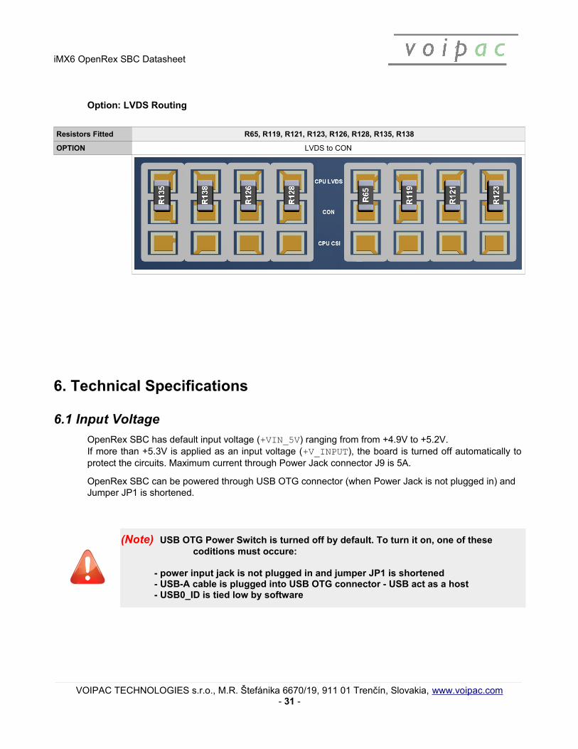
Option: LVDS Routing
Resistors Fitted R65, R119, R121, R123, R126, R128, R135, R138
OPTION LVDS to CON
6. Technical Specifications
6.1 Input Voltage
OpenRex SBC has default input voltage (+VIN_5V) ranging from from +4.9V to +5.2V.If more than +5.3V is applied as an input voltage (+V_INPUT), the board is turned off automatically to protect the circuits. Maximum current through Power Jack connector J9 is 5A.
OpenRex SBC can be powered through USB OTG connector (when Power Jack is not plugged in) and Jumper JP1 is shortened.
(Note) USB OTG Power Switch is turned off by default. To turn it on, one of these coditions must occure:
- power input jack is not plugged in and jumper JP1 is shortened- USB-A cable is plugged into USB OTG connector - USB act as a host- USB0_ID is tied low by software
VOIPAC TECHNOLOGIES s.r.o., M.R. Štefánika 6670/19, 911 01 Trenčín, Slovakia, www.voipac.com- 31 -

iMX6 OpenRex SBC Datasheet
6.2 Mechanical
Dimmensions Width Length Height Unit
PCB 70 (2.755906 ) 95 (3.740158 ) 1.6 (0.06299213 ) mm (inch)
Dimensions (in millimeters)
VOIPAC TECHNOLOGIES s.r.o., M.R. Štefánika 6670/19, 911 01 Trenčín, Slovakia, www.voipac.com- 32 -

iMX6 OpenRex SBC Datasheet
6.3 Temperature Range
Symbol Description Min Max Unit Standard Unit Range
T_AMB Operating temperature range - COMMERCIAL 0 +70 °C X
T_AMB Operating temperature range - EXTENDED -20 +70 °C
6.4 CE compliance of Voipac productsThe CE label is a mandatory conformity mark for complex electronic devices placed on the market in the European Economic Area and each product sold within the EU needs a CE Certificate of Conformance that ensures that the product conforms to the essential requirements of the applicable EC directives.
However, if such complex electronic devices are produced for further processing by the industry, skilled development teams or system integrators, they do not need to observe the above mentioned CE requirements and consequently do not need any identification either. This applies to the Voipac Single Board Computers, because these are not used as stand-alone devices by the general public.
To make sure that Voipac SBCs can be used in CE marked devices, they are designed to obey the EC directivesand the standard configuration SBCs manufactured by Voipac are tested for Electromagnetic Interference and operating temperature ranges.
6.5 RoHS and WEEE Compliance
All of the products designed and manufactured by Voipac are classified as Electrical and Electronic Equipment (EEE) under the Directive on the restriction of the use of certain hazardous substances in electrical and electronic equipment 2002/95/EC (RoHS). To comply with the RoHS directive, the restricted use of Lead (Pb), Mercury (Hg), Cadmium (Cd), Hexavalent Chromium (Cr 6+), Polybrominated Biphenyls (PBB) and Polybrominated Diphenyl Ethers (PBDE) must be ensured. Voipac guarantees that products ordered after July 1,2006 are assembled in full compliance with the RoHS directive from the European Parliament and Counsel. The company procedures also complies with the Waste Electrical and Electronic Equipment Directive 2002/96/EC (WEEE).
VOIPAC TECHNOLOGIES s.r.o., M.R. Štefánika 6670/19, 911 01 Trenčín, Slovakia, www.voipac.com- 33 -

Warranty:VOIPAC TECHNOLOGIES s.r.o. Does Not Bear Responsibility for the Following:
• Failure of a product resulting from misuse, accident, modification, unsuitableoperating environment, or improper maintenance by user
• Unless otherwise agreed in written, a product does not include technical support and the customer may be able to purchase technical support under separate agreement
• Any technical or other support provided by VOIPAC TECHNOLOGIES s.r.o. such as assistance, set-up and installation is provided WITHOUT WARRANTY OF ANY KIND.
Disclaimer:VOIPAC TECHNOLOGIES s.r.o. reserves the right to make changes, without notice, to any product, includingcircuits and/or software described or contained in this datasheet. VOIPAC TECHNOLOGIES s.r.o. assumes noresponsibility or liability for the use of the described product(s), conveys no license or title under any patent,copyright, or mask work rights to these products, and makes no representations or warranties that theseproducts are free from patent, copyright, or mask work right infringement, unless otherwise specified.
Trademark Acknowledgment:Brand and product names are trademarks or registered trademarks of their respective owners.