Embed Size (px)
Citation preview
In a
PIn
ch
: Us
Ing
2 To
ols
To B
ala
nc
e c
UTTIn
g Fo
rc
es
dptechnology.com 1
technologyspotlight
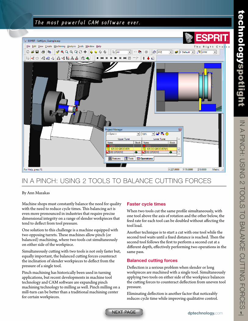
In a PInch: UsIng 2 Tools To Balance cUTTIng Forces
By Ann Mazakas
Machine shops must constantly balance the need for quality with the need to reduce cycle times. This balancing act is even more pronounced in industries that require precise dimensional integrity on a range of slender workpieces that tend to deflect from tool pressure.One solution to this challenge is a machine equipped with two opposing turrets. These machines allow pinch (or balanced) machining, where two tools cut simultaneously on either side of the workpiece.Simultaneously cutting with two tools is not only faster but, equally important, the balanced cutting forces counteract the inclination of slender workpieces to deflect from the pressure of a single tool.Pinch machining has historically been used in turning applications, but recent developments in machine tool technology and CAM software are expanding pinch machining technology to milling as well. Pinch milling on a mill-turn can be better than a traditional machining center for certain workpieces.
Faster cycle times
When two tools cut the same profile simultaneously, with one tool above the axis of rotation and the other below, the feed rate for each tool can be doubled without affecting the tool load.Another technique is to start a cut with one tool while the second tool waits until a fixed distance is reached. Then the second tool follows the first to perform a second cut at a different depth, effectively performing two operations in the same pass.
Balanced cutting forces
Deflection is a serious problem when slender or long workpieces are machined with a single tool. Simultaneously applying two tools on either side of the workpiece balances the cutting forces to counteract deflection from uneven tool pressure.Eliminating deflection is another factor that noticeably reduces cycle time while improving qualitative control.
2dptechnology.com
In a
PIn
ch
: Us
Ing
2 To
ols
To B
ala
nc
e c
UTTIn
g Fo
rc
es
technologyspotlight
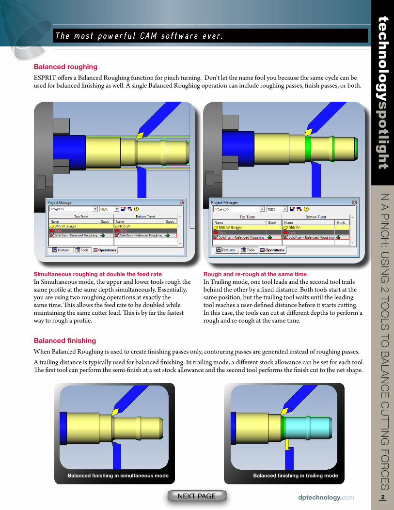
Balanced roughing
ESPRIT offers a Balanced Roughing function for pinch turning. Don’t let the name fool you because the same cycle can be used for balanced finishing as well. A single Balanced Roughing operation can include roughing passes, finish passes, or both.
Balanced finishing
When Balanced Roughing is used to create finishing passes only, contouring passes are generated instead of roughing passes.A trailing distance is typically used for balanced finishing. In trailing mode, a different stock allowance can be set for each tool. The first tool can perform the semi-finish at a set stock allowance and the second tool performs the finish cut to the net shape.
Simultaneous roughing at double the feed rateIn Simultaneous mode, the upper and lower tools rough the same profile at the same depth simultaneously. Essentially, you are using two roughing operations at exactly the same time. This allows the feed rate to be doubled while maintaining the same cutter load. This is by far the fastest way to rough a profile.
Rough and re-rough at the same timeIn Trailing mode, one tool leads and the second tool trails behind the other by a fixed distance. Both tools start at the same position, but the trailing tool waits until the leading tool reaches a user-defined distance before it starts cutting. In this case, the tools can cut at different depths to perform a rough and re-rough at the same time.
Balanced finishing in simultaneous mode Balanced finishing in trailing mode
3dptechnology.com
In a
PIn
ch
: Us
Ing
2 To
ols
To B
ala
nc
e c
UTTIn
g Fo
rc
es
technologyspotlight
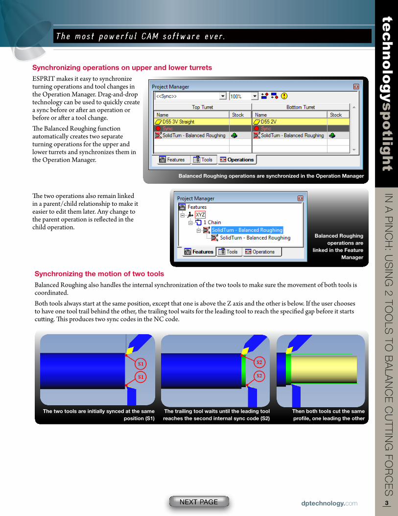
Synchronizing operations on upper and lower turrets
ESPRIT makes it easy to synchronize turning operations and tool changes in the Operation Manager. Drag-and-drop technology can be used to quickly create a sync before or after an operation or before or after a tool change.The Balanced Roughing function automatically creates two separate turning operations for the upper and lower turrets and synchronizes them in the Operation Manager.
Synchronizing the motion of two tools
Balanced Roughing also handles the internal synchronization of the two tools to make sure the movement of both tools is coordinated.Both tools always start at the same position, except that one is above the Z axis and the other is below. If the user chooses to have one tool trail behind the other, the trailing tool waits for the leading tool to reach the specified gap before it starts cutting. This produces two sync codes in the NC code.
Balanced Roughing operations are
linked in the Feature Manager
Balanced Roughing operations are synchronized in the Operation Manager
The two operations also remain linked in a parent/child relationship to make it easier to edit them later. Any change to the parent operation is reflected in the child operation.
the two tools are initially synced at the same position (S1)
the trailing tool waits until the leading tool reaches the second internal sync code (S2)
then both tools cut the same profile, one leading the other
4dptechnology.com
In a
PIn
ch
: Us
Ing
2 To
ols
To B
ala
nc
e c
UTTIn
g Fo
rc
es
technologyspotlight
Perform your own balancing act
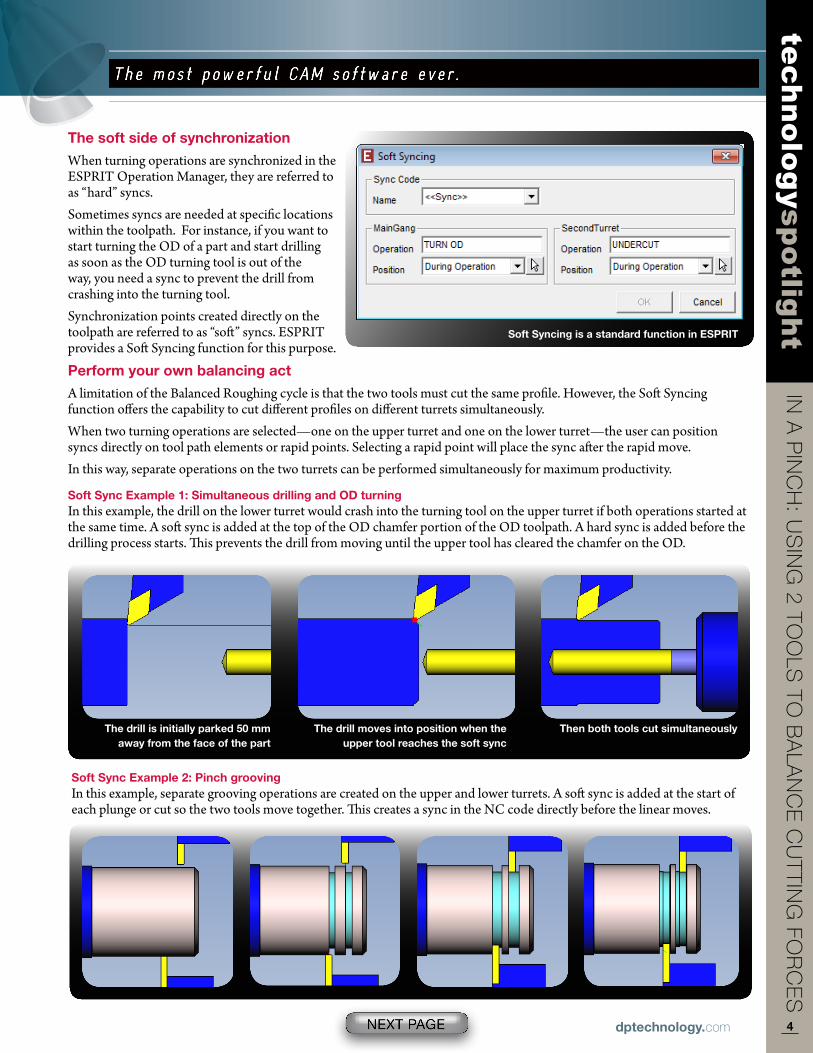
A limitation of the Balanced Roughing cycle is that the two tools must cut the same profile. However, the Soft Syncing function offers the capability to cut different profiles on different turrets simultaneously.When two turning operations are selected—one on the upper turret and one on the lower turret—the user can position syncs directly on tool path elements or rapid points. Selecting a rapid point will place the sync after the rapid move.In this way, separate operations on the two turrets can be performed simultaneously for maximum productivity.
Soft Syncing is a standard function in eSPRIt
the soft side of synchronization
When turning operations are synchronized in the ESPRIT Operation Manager, they are referred to as “hard” syncs.Sometimes syncs are needed at specific locations within the toolpath. For instance, if you want to start turning the OD of a part and start drilling as soon as the OD turning tool is out of the way, you need a sync to prevent the drill from crashing into the turning tool.Synchronization points created directly on the toolpath are referred to as “soft” syncs. ESPRIT provides a Soft Syncing function for this purpose.
Soft Sync example 1: Simultaneous drilling and OD turningIn this example, the drill on the lower turret would crash into the turning tool on the upper turret if both operations started at the same time. A soft sync is added at the top of the OD chamfer portion of the OD toolpath. A hard sync is added before the drilling process starts. This prevents the drill from moving until the upper tool has cleared the chamfer on the OD.
Soft Sync example 2: Pinch groovingIn this example, separate grooving operations are created on the upper and lower turrets. A soft sync is added at the start of each plunge or cut so the two tools move together. This creates a sync in the NC code directly before the linear moves.
the drill is initially parked 50 mm away from the face of the part
the drill moves into position when the upper tool reaches the soft sync
then both tools cut simultaneously
5dptechnology.com
In a
PIn
ch
: Us
Ing
2 To
ols
To B
ala
nc
e c
UTTIn
g Fo
rc
es
technologyspotlight
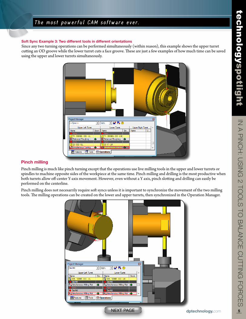
Pinch milling
Pinch milling is much like pinch turning except that the operations use live milling tools in the upper and lower turrets or spindles to machine opposite sides of the workpiece at the same time. Pinch milling and drilling is the most productive when both turrets allow off-center Y-axis movement. However, even without a Y axis, pinch slotting and drilling can easily be performed on the centerline.Pinch milling does not necesarrily require soft syncs unless it is important to synchronize the movement of the two milling tools. The milling operations can be created on the lower and upper turrets, then synchronized in the Operation Manager.
Soft Sync example 3: two different tools in different orientationsSince any two turning operations can be performed simultaneously (within reason), this example shows the upper turret cutting an OD groove while the lower turret cuts a face groove. These are just a few examples of how much time can be saved using the upper and lower turrets simultaneously.
6dptechnology.com
In a
PIn
ch
: Us
Ing
2 To
ols
To B
ala
nc
e c
UTTIn
g Fo
rc
es
technologyspotlight
DP technology Corp. Phone: 1 800 627-84791150 avenida acaso Outside the US: + 1 805 388-6000Camarillo, Ca 93012 USa email: [email protected]
eSPRIt is a registered trademark of DP technology Corp. ©2011 DP technology Corp. all rights reserved.
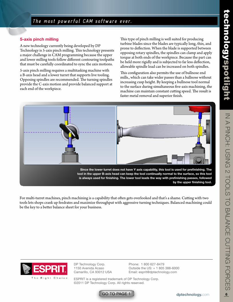
5-axis pinch milling
A new technology currently being developed by DP Technology is 5-axis pinch milling. This technology presents a major challenge in CAM programming because the upper and lower milling tools follow different contouring toolpaths that must be carefully coordinated to sync the axis motions.5-axis pinch milling requires a multitasking machine with a B-axis head and a lower turret that supports live tooling. Opposing spindles are recommended. The turning spindles provide the C-axis motion and provide balanced support at each end of the workpiece.
This type of pinch milling is well suited for producing turbine blades since the blades are typically long, thin, and prone to deflection. When the blade is supported between opposing rotary spindles, the spindles can clamp and apply torque at both ends of the workpiece. Because the part can be held more rigidly and is subjected to far less deflection, allowable spindle load can be increased on both spindles.This configuration also permits the use of bullnose end mills., which can take wider passes than a ballnose without increasing cusp height. By keeping a bullnose tool normal to the surface during simultaneous five-axis machining, the machine can maintain constant cutting speed. The result is faster metal removal and superior finish.
For multi-turret machines, pinch machining is a capability that often gets overlooked and that’s a shame. Cutting with two tools lets shops crank up feedrates and maximize throughput with aggressive turning techniques. Balanced machining could be the key to a better balance sheet for your business.
Since the lower turret does not have Y axis capability, this tool is used for prefinishing. the tool in the upper B-axis head can keep the tool continually normal to the surface, so this tool is always used for finishing. the lower tool leads the way with prefinishing passes, followed
by the upper finishing tool.