Embed Size (px)
Citation preview

8055T CNC
EXAMPLE MANUAL
Ref. 9907 (ing)

The cutting speeds and feedrates appearing in this manual are only approximate,they may vary depending on the material of the part and the tools used. Whenmachining one of the parts of these examples, use the speeds recommended bythe tool manufacturer.
The tool number will also be different depending on the machine.
WARNING
INDEX
Tool s ............................................................................................... 1
Tool calibratio n ............................................................................. 2
General example s ......................................................................... 5
Canned cycle s ..............................................................................11
«C» axis programmin g ............................................................... 33
Profile Edito r ................................................................................ 37
User screen customizing program s ........................................ 43

EXAMPLE MANUAL 1
8055T CNC
TOOLS
List of tools used in these examples:

2 EXAMPLE MANUAL
8055T CNC
TOOL CALIBRA TION
Example of how to calibrate tool T2 using a part of known dimenstions(diameter: 60 mm, length: 100 mm).
Note: The X axis operates in diameter.

EXAMPLE MANUAL 3
8055T CNC
Calibrating procedure
1. Edit the tool and tool offset tables with all the data known for each tool.
Tool table: T2 D2 F0 N0 R0
Tool offset table: D2 X0 Z0 R0.4 F3 I0 K0
Tool geometry table T2 NOSEA 60 NOSEW 7 CUTA 100
2. Select the tool and tool offset to be calibrated.
Press the softkey sequence: [Main menu] [JOG] [MDI] T2 D2
3. Select the tool calibration mode and do it along the X axis.
- Press the softkey sequence: [Main menu] [JOG] [Calibration] [+] [X]
- The CNC requests: Preset the X axis:
- Enter tool diameter 60 [Enter]
- The CNC shows the text Tool calibration.
- Move the tool with the JOG keys until touching the part.
- Press the softkey: [Load X axis]
- The CNC shows the text Offset updated.
4. Calibrate the tool along the Z axis.
- Press the softkey: [Z]
- The CNC requests: Preset the Z axis:
- Enter tool length 100 [Enter]
- The CNC shows the text Tool calibration.
- Move the tool with the JOG keys until touching the part.
- Press the softkey: [Load X axis]
- The CNC shows the text Offset updated.
If accessing the tool offset table next ...
Press the softkey sequence: [Main menu] [Tables] [Tool offsets]
... Offset D2 will show, for example, the following values:
D 2 X 57.456 Z 29.312 R 0.4 F 3 I 0 K 0
Note: The values shown by the “X” field are always in radius.

5
Programming examples:
General examples
8055T
Zero offset. ..................................................................................................... 6
Programming in absolute (G90) and incremental (G91) coordinates. .............. 7
Programming of arcs (G02/G03). (Programming in radius) .............................. 8
Programming of arcs (G02/G03). (Programming in diameters) ........................ 9
Tangential entry/exit (G37/G38) and corner rounding(G36) with tool radiuscompensation (G40/G41/G42). ................................................................ 10

6 EXAMPLE MANUAL
8055T CNC
Zero offset.
This example shows two ways to do this operation: manual mode and by program. Both methods use zero offsetG54.
Manual mode:
1. Select the zero offset table.
Press the sequence of keys and softkeys: [Main menu] [Tables] [Zero offsets]
2. Edit the table for zero offset G54.
Press the sequence of keys and softkeys: [Edit] G54 X0 Z120 [Enter]
3. Select zero offset G54.
Press the sequence of keys and softkeys: [Main menu] [JOG] [MDI] G54
By program:
One of the following methods must be used.
- Execute, in MDI mode, the following program blocks and then execute the part-program.
- Edit a program with the following blocks and execute it before the part-program.
- Include the following blocks at the beginning of the machining program.
Program blocks.
(ORGX54=0, ORGZ54=120) ...................... Assigns the values X0 Z120 to the G54 zero offset table.G54............................................................... Selects and applies zero offset G54.
Being the Machine Zero point (home: 0.0), the face of the part, point (120,0) is going to be the new Part Zero.

EXAMPLE MANUAL 7
8055T CNC
Programming in absolute (G90) and incremental (G91) coordinates.
Programming in radius
Absolute coordinates (G90)
G90 G95 G96 F0.15 S180 T2 D2 M4 M41G0 X50 Z100G1 X0 Z80 ..................................... Point AG1 X15 Z65 ................................... Section A-BZ55 .................................................. Section B-CX40 Z30 ......................................... Section C-DZ0 .................................................... Section D-EG0 X50 Z100M30
Incremental coordinates (G91)
G90 G95 G96 F0.15 S180 T2 D2 M4 M41G0 X50 Z100G1 X0 Z80 ..................................... Point AG1 G91 X15 Z-15 ........................ Section A-BZ-10 ................................................ Section B-CX25 Z-25 ....................................... Section C-DZ-30 ................................................ Section D-EG0 G90 X50 Z100M30
Programming in diameters
Absolute coordinates (G90)
G90 G95 G96 F0.15 S180 T2 D2 M4 M41G0 X100 Z100G1 X0 Z80 ..................................... Point AG1 X30 Z65 ................................... Section A-BZ55 .................................................. Section B-CX80 Z30 ......................................... Section C-DZ0 .................................................... Section D-EG0 X100 Z100M30
Incremental coordinates (G91)
G90 G95 G96 F0.15 S180 T2 D2 M4 M41G0 X100 Z100G1 X0 Z80 ..................................... Point AG1 G91 X30 Z-15 ........................ Section A-BZ-10 ................................................ Section B-CX50 Z-25 ....................................... Section C-DZ-30 ................................................ Section D-EG0 G90 X100 Z100M30

8 EXAMPLE MANUAL
8055T CNC
Programming of arcs (G02/G03). (Programming in radius)
Programming the arc center
Absolute coordinates (G90)
G90 G95 G96 F0.15 S180 T2 D2 M4G0 X60 Z120G1 X0 Z90 ..................................... Point AG3 X20 Z70 I0 K-20 .................. Section A-BG1 Z60 ........................................... Section B-CG2 X30 Z30 I50 K0 .................... Section C-DG1 X40 ........................................... Section D-EG3 X50 Z10 I-19.9 K-22.45 ... Section E-FG1 Z0 ............................................. Section F-GG0 X60 Z120M30
Incremental coordinates (G91)
G90 G95 G96 F0.15 S180 T2 D2 M4G0 X60 Z120G1 X0 Z90 ...................................... Point AG91 G3 X20 Z-20 I0 K-20 ........ Section A-BG1 Z-10 .......................................... Section B-CG2 X10 Z-30 I50 K0 ................... Section C-DG1 X10 ............................................ Section D-EG3 X10 Z-20 I-19.9 K-22.45 . Section E-FG1 Z-10 .......................................... Section F-GG0 G90 X60 Z120M30
Programming the arc radius
Absolute coordinates (G90)
G90 G95 G96 F0.15 S180 T2 D2 M4G0 X60 Z120G1 X0 Z90 ..................................... Point AG3 X20 Z70 R20 .......................... Section A-BG1 Z60 ........................................... Section B-CG2 X30 Z30 R50 .......................... Section C-DG1 X40 ........................................... Section D-EG3 X50 Z10 R30 .......................... Section E-FG1 Z0 ............................................. Section F-GG0 X60 Z120M30
Incremental coordinates (G91)
G90 G95 G96 F0.15 S180 T2 D2 M4G0 X60 Z120G1 X0 Z90 ...................................... Point AG91 G3 X20 Z-20 R20 ................ Section A-BG1 Z-10 .......................................... Section B-CG2 X10 Z-30 R50 ......................... Section C-DG1 X10 ............................................ Section D-EG3 X10 Z-20 R30 ......................... Section E-FG1 Z-10 .......................................... Section F-GG0 G90 X60 Z120M30

EXAMPLE MANUAL 9
8055T CNC
Programming of arcs (G02/G03). (Programming in diameters)
Programming the arc center
Absolute coordinates (G90)
G90 G95 G96 F0.15 S180 T2 D2 M4G0 X120 Z120G1 X0 Z90 ..................................... Point AG3 X40 Z70 I0 K-20 .................. Section A-BG1 Z60 ........................................... Section B-CG2 X60 Z30 I50 K0 .................... Section C-DG1 X80 ........................................... Section D-EG3 X100 Z10 I-19.9 K-22.45 Section E-FG1 Z0 ............................................. Section F-GG0 X120 Z120M30
Incremental coordinates (G91)
G90 G95 G96 F0.15 S180 T2 D2 M4G0 X120 Z120G1 X0 Z90 ..................................... Point AG91 G3 X40 Z-20 I0 K-20 ....... Section A-BG1 Z-10 ......................................... Section B-CG2 X20 Z-30 I50 K0 .................. Section C-DG1 X20 ........................................... Section D-EG3 X20 Z-20 I-19.9 K-22.45 Section E-FG1 Z-10 ......................................... Section F-GG0 G90 X60 Z120M30
Programming the arc radius
Absolute coordinates (G90)
G90 G95 G96 F0.15 S180 T2 D2 M4G0 X120 Z120G1 X0 Z90 ..................................... Point AG3 X40 Z70 R20 .......................... Section A-BG1 Z60 ........................................... Section B-CG2 X60 Z30 R50 .......................... Section C-DG1 X80 ........................................... Section D-EG3 X100 Z10 R30 ........................ Section E-FG1 Z0 ............................................. Section F-GG0 X120 Z120M30
Incremental coordinates (G91)
G90 G95 G96 F0.15 S180 T2 D2 M4G0 X120 Z120G1 X0 Z90 ..................................... Point AG91 G3 X40 Z-20 R20 ............... Section A-BG1 Z-10 ......................................... Section B-CG2 X20 Z-30 R50 ........................ Section C-DG1 X20 ........................................... Section D-EG3 X20 Z-20 R30 ........................ Section E-FG1 Z-10 ......................................... Section F-GG0 G90 X60 Z120M30
10 EXAMPLE MANUAL
8055T CNC
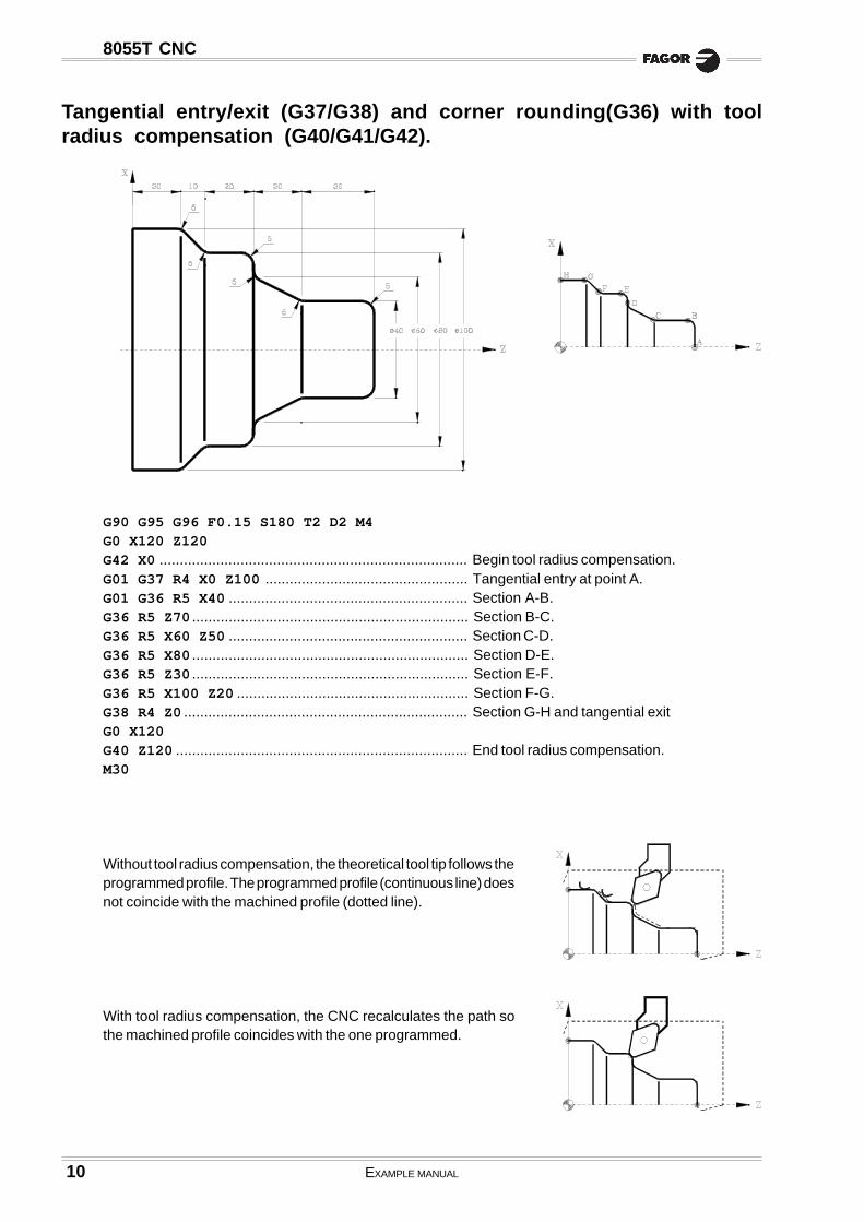
Tangential entry/exit (G37/G38) and corner rounding(G36) with toolradius compensation (G40/G41/G42).
G90 G95 G96 F0.15 S180 T2 D2 M4G0 X120 Z120G42 X0 ............................................................................ Begin tool radius compensation.G01 G37 R4 X0 Z100 .................................................. Tangential entry at point A.G01 G36 R5 X40 ........................................................... Section A-B.G36 R5 Z70 .................................................................... Section B-C.G36 R5 X60 Z50 ........................................................... Section C-D.G36 R5 X80 .................................................................... Section D-E.G36 R5 Z30 .................................................................... Section E-F.G36 R5 X100 Z20 ......................................................... Section F-G.G38 R4 Z0 ...................................................................... Section G-H and tangential exitG0 X120G40 Z120 ........................................................................ End tool radius compensation.M30
Without tool radius compensation, the theoretical tool tip follows theprogrammed profile. The programmed profile (continuous line) doesnot coincide with the machined profile (dotted line).
With tool radius compensation, the CNC recalculates the path sothe machined profile coincides with the one programmed.
11
Programming examples:
Canned cycles
8055T
Inside turning of arcs and outside turning of straight sections. ...................... 12
Inside arc facing and outside straight turning. ............................................... 14
Inside straight facing and outside arc facing. ................................................ 16
Inside roughing on the Z axis and outside arc turning. .................................. 18
Inside straight turning and outside roughing on the Z axis. ........................... 20
Inside and outside roughing on the X axis. .................................................... 22
Inside and outside taper threading. ............................................................... 24
Inside and outside roughing on X. Outside grooving and threading. ............... 26
Outside pattern repeat. Inside grooving and threading. .................................. 28
Inside and outside roughing on the X axis ..................................................... 30
12 EXAMPLE MANUAL
8055T CNC
Inside turning of arcs and outside turning of straight sections.
First fixture:
Set part zero
(ORGX54=0, ORGZ54=112)G54G92 S2200
Operation 1 (Drilling)
G94 G97 F90 S600 M4Z150T9 D9G0 X0 Z8G83 X0 Z0 I45.773 B9 D4 K0 H0 C1G0 Z150
Operation 2 (Inside arc turning)
G95 G96 F0.2 S120 M4T8 D8G0 X20 Z20G1 G41 X18 Z5G84 X70 Z0 Q20 R-33.541 C2 L0.3 M0.3 H0.1 I-35 K0G0 G40 Z150
Operation 3 (Facing and outside turning)
G95 G96 F0.2 S180 M4T2 D2G0 X90 Z20G1 X78 Z5G1 Z-40G1 X85G0 Z0G1 X66G1 Z5G1 G42 X72 Z1G1 X80 Z-3G0 G40 Z150
Stock dimensions: Ø80x114mm

EXAMPLE MANUAL 13
8055T CNC
Second fixture:
Set new part zero
(MSG “* NEW FIXTURE - REVERSE PART *”)M0 M5(MSG “”)(ORGX54=0, ORGZ54=110)G54G92 S2200
Operation 4 (Taper turning and facing)
G95 G96 F0.2 S180 M4G0 X90 Z20G1 G42 X84 Z5G81 X10 Z0 Q78 R-75 C2 L0.3 M0.3 H0.1G0 G40 X14 Z0G1 X-0.4G0 Z150M30

14 EXAMPLE MANUAL
8055T CNC
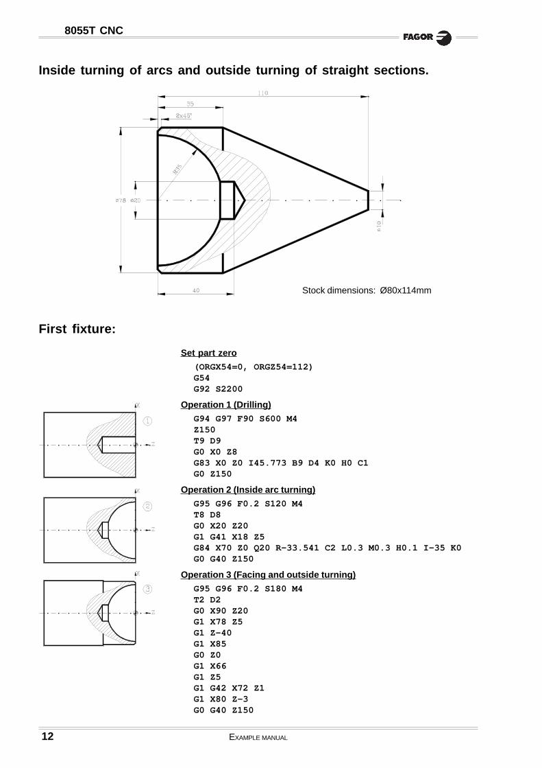
Inside arc facing and outside straight turning.
First fixture:
Set part zero
(ORGX54=0, ORGZ54=67)G54G92 S2200
Operation 1 (Drilling)
G94 G97 F90 S600 M4Z150T9 D9G0 X0 Z8G83 X0 Z0 I38.773 B3 D7 K0 H0 C4G0 Z150
Operation 2 (Facing and outside turning)
G95 G96 F0.2 S180 M4T2 D2G0 X90 Z20G1 X85 Z0G1 X18G1 Z5G0 G42 X72 Z1G1 X78 Z-2Z-40X85G0 Z150
Operation 3 (Inside arc facing)
G95 G96 F0.2 S100 M4T8 D8G0 X20 Z20G1 G42 X17 Z2G85 X20 Z-25 Q70 R0 C1.4 L0.3 M0.3 H0.1 I-28.043 K53.043G0 G40 Z150
Stock dimensions: Ø80x69mm.
EXAMPLE MANUAL 15
8055T CNC
Second fixture:
Set new part zero
(MSG “* NEW FIXTURE - REVERSE PART *”)M0 M5(MSG “”)(ORGX54=0, ORGZ54=65)G54G92 S2200
Operation 4 (Outside taper facing)
G95 G96 F0.2 S180 M4T2 D2G0 X90 Z20G1 G41 X83 Z5G82 X78 Z-33 Q10 R0 C2 L0.3 M0.3 H0.1G0 G40 X14 Z0G1 X-0.4G0 Z150M30

16 EXAMPLE MANUAL
8055T CNC
Inside straight facing and outside arc facing.
Stock dimensions: Ø80x84mm
First fixture:
Set part zero
(ORGX54=0, ORGZ54=82)G54G92 S2200
Operation 1 (Drilling)
G95 G97 F0.15 S600 M4Z150T9 D9G0 X0 Z8G83 X0 Z0 I40.773 B3 D7 K10 H0 C4G0 Z150
Operation 2 (Inside taper facing)
G95 G96 F0.2 S100 M4T8 D8G0 X20 Z20G1 G42 X18 Z5G82 X20 Z-21.732 Q70 R0 C2 L0.2 M0.2 F0.15 H0.1G0 G40 Z150
Operation 3 (Facing and outside turning)
G95 G96 F0.2 S180 M4T2 D2G0 X90 Z20G1 X78 Z5G1 Z-40G1 X85G0 Z0G1 X66G1 Z5G1 G42 X72 Z1G1 X80 Z-3G0 G40 Z150

EXAMPLE MANUAL 17
8055T CNC
Second fixture:
Set new part zero
(MSG “* NEW FIXTURE - REVERSE PART *”)M0 M5(MSG “”)(ORGX54=0, ORGZ54=80)G54G92 S2200
Operation 4 (Outside arc facing)
G95 G96 F0.2 S180 M4T2 D2G0 X90 Z20G41 X84 Z5G85 X78 Z-27 Q10 R0 C1.5 L0.3 M0.3 H0.1 I-45.011 K-21.772G0 G40 X14 Z0G1 X-0.4 F0.2G0 Z150M30

18 EXAMPLE MANUAL
8055T CNC
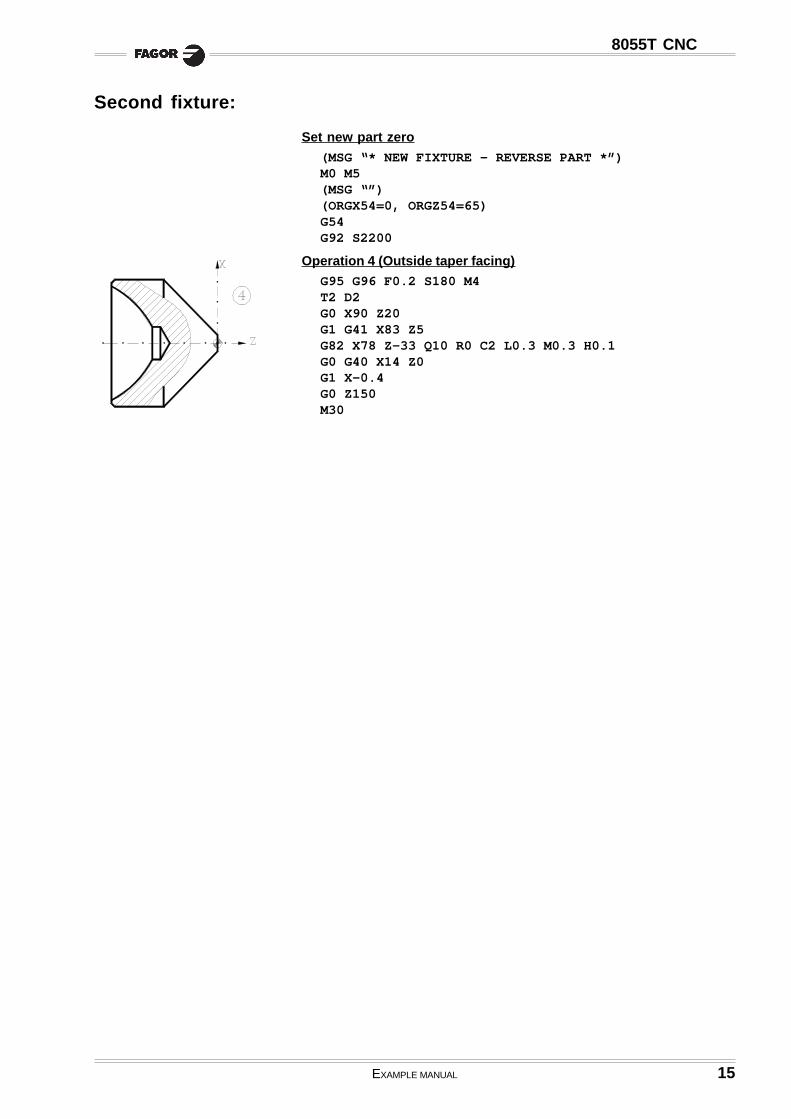
Inside roughing on the Z axis and outside arc turning.
First fixture:
Set part zero
(ORGX54=0, ORGZ54=82)G54G92 S2200
Operation 1 (Drilling)
G94 G97 F90 S600 T9 M4Z150T9 D9G0 X0 Z8G83 X0 Z0 I35.773 B5 D5 K15 H0 C1.5G0 Z150
Operation 2 (Inside profile facing)
G95 G96 F0.2 S100 M4T8 D8G0 X20 Z20G1 X16 Z5G69 X20 Z-25 C1.5 L0.3 H0.1 S100 E110(GOTO N120)N100 G1 X30 Z-25 X39.755 Z-15 G2 X70 Z-5 I-5.29 K24.434N110 G1 X70 Z4N120 G0 Z150
Stock dimensions: Ø80x84mm
EXAMPLE MANUAL 19
8055T CNC
Operation 3 (Facing and outside turning)
G95 G96 F0.2 S180 M4T2 D2G0 X90 Z20G1 X78 Z5G1 Z-40G1 X85G0 Z0G1 X66G1 Z5G1 G42 X72 Z1G1 X80 Z-3G0 G40 Z150
Second fixture:
Set new part zero
(MSG “* NEW FIXTURE - REVERSE PART *”)M0 M5(MSG “”)(ORGX54=0, ORGZ54=80)G54G92 S2200
Operation 4 (Outside arc turning)
G95 G96 F0.2 S180 M4T2 D2G0 X90 Z20G1 G42 X84 Z5G84 X0 Z0 Q78 R-48.775 C2 L0.3 M0.3 H0.1 I-11 K-48.775G0 G40 Z150M30
20 EXAMPLE MANUAL
8055T CNC
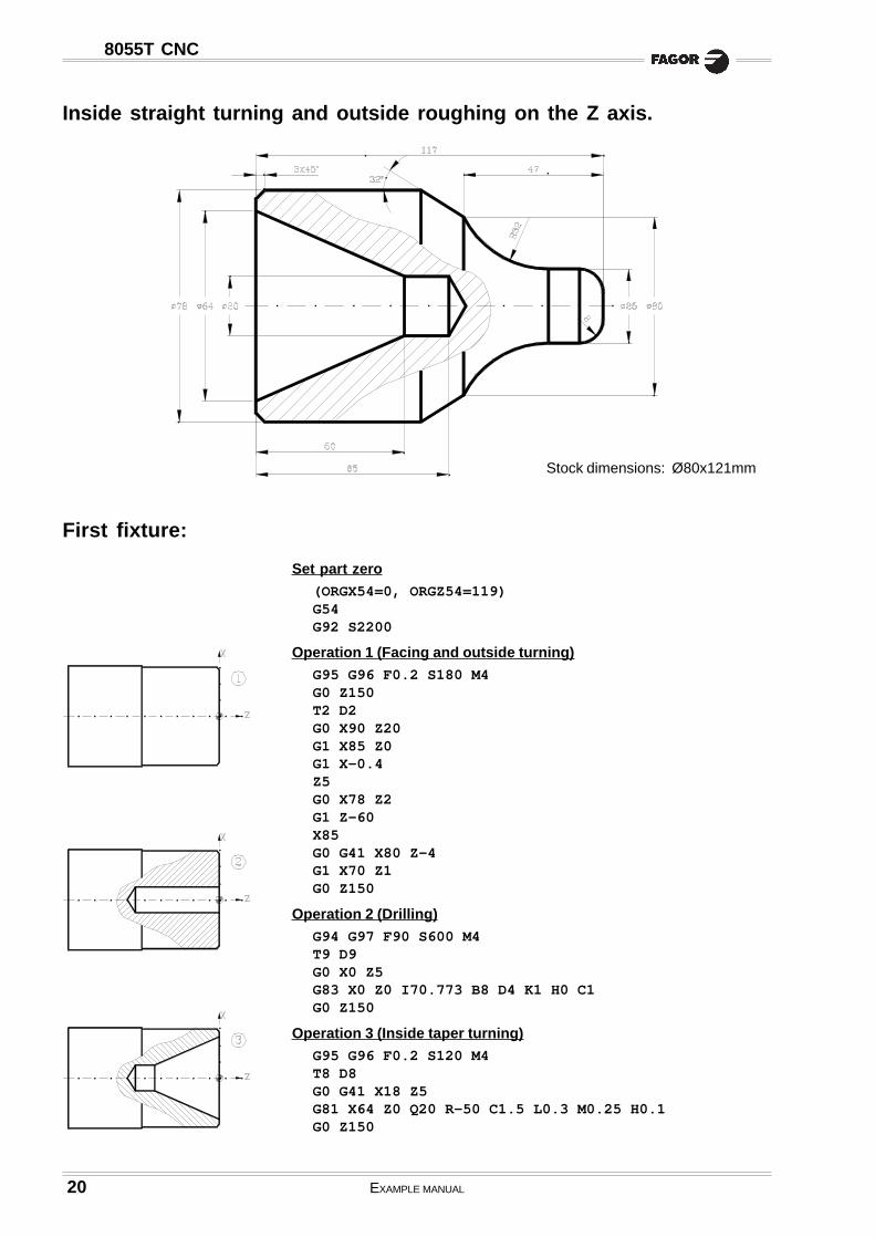
Inside straight turning and outside roughing on the Z axis.
First fixture:
Set part zero
(ORGX54=0, ORGZ54=119)G54G92 S2200
Operation 1 (Facing and outside turning)
G95 G96 F0.2 S180 M4G0 Z150T2 D2G0 X90 Z20G1 X85 Z0G1 X-0.4Z5G0 X78 Z2G1 Z-60X85G0 G41 X80 Z-4G1 X70 Z1G0 Z150
Operation 2 (Drilling)
G94 G97 F90 S600 M4T9 D9G0 X0 Z5G83 X0 Z0 I70.773 B8 D4 K1 H0 C1G0 Z150
Operation 3 (Inside taper turning)
G95 G96 F0.2 S120 M4T8 D8G0 G41 X18 Z5G81 X64 Z0 Q20 R-50 C1.5 L0.3 M0.25 H0.1G0 Z150
Stock dimensions: Ø80x121mm

EXAMPLE MANUAL 21
8055T CNC
Second fixture:
Set new part zero
(MSG “* NEW FIXTURE - REVERSE PART *”)M0 M5(MSG “”)(ORGX54=0, ORGZ54=117)G54G92 S2200
Operation 4 (Outside profile facing)
G95 G96 F0.2 S180 M4T2 D2G0 X90 Z20G1 X85 Z5G69 X78 Z-61.403 C1 L0.3 H0.1 S100 E110(GOTO N120)N100 G1 G5 X60 Z-47 G3 X25 Z-18.474 I14.5 K28.526 G1 G36 R8 X25 Z0N110 X-0.4 Z0N120 G0 Z150M30
22 EXAMPLE MANUAL
8055T CNC
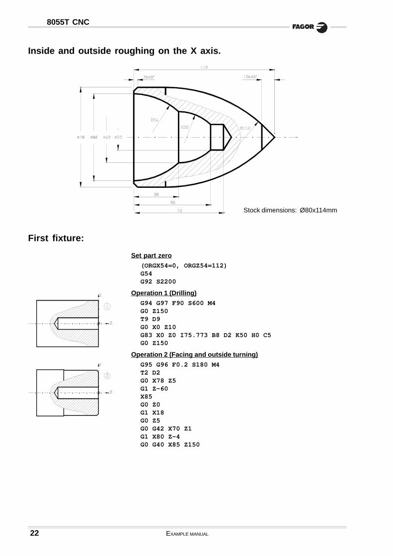
Inside and outside roughing on the X axis.
First fixture:
Set part zero
(ORGX54=0, ORGZ54=112)G54G92 S2200
Operation 1 (Drilling)
G94 G97 F90 S600 M4G0 Z150T9 D9G0 X0 Z10G83 X0 Z0 I75.773 B8 D2 K50 H0 C5G0 Z150
Operation 2 (Facing and outside turning)
G95 G96 F0.2 S180 M4T2 D2G0 X78 Z5G1 Z-60X85G0 Z0G1 X18G0 Z5G0 G42 X70 Z1G1 X80 Z-4G0 G40 X85 Z150
Stock dimensions: Ø80x114mm
EXAMPLE MANUAL 23
8055T CNC
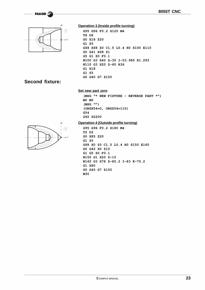
Operation 3 (Inside profile turning)
G95 G96 F0.2 S120 M4T8 D8G0 X18 Z20G1 Z5G68 X68 Z0 C1.5 L0.4 H0 S100 E110G0 G41 X68 Z1G5 G1 Z0 F0.1N100 G3 X40 Z-35 I-53.985 K1.293N110 G3 X20 Z-60 R36G1 X18G1 Z5G0 G40 G7 Z150
Second fixture:
Set new part zero
(MSG “* NEW FIXTURE - REVERSE PART *”)M0 M5(MSG “”)(ORGX54=0, ORGZ54=110)G54G92 S2200
Operation 4 (Outside profile turning)
G95 G96 F0.2 S180 M4T2 D2G0 X85 Z20G1 Z5G68 X0 Z0 C1.5 L0.4 H0 S150 E160G0 G42 X0 Z10G1 G5 Z0 F0.1N150 G1 X20 Z-10N160 G3 X78 Z-85.2 I-83 K-75.2G1 X80G0 G40 G7 Z150M30
24 EXAMPLE MANUAL
8055T CNC
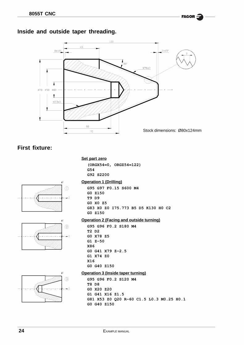
Inside and outside taper threading.
First fixture:
Set part zero
(ORGX54=0, ORGZ54=122)G54G92 S2200
Operation 1 (Drilling)
G95 G97 F0.15 S600 M4G0 Z150T9 D9G0 X0 Z5G83 X0 Z0 I75.773 B5 D5 K130 H0 C2G0 Z150
Operation 2 (Facing and outside turning)
G95 G96 F0.2 S180 M4T2 D2G0 X78 Z5G1 Z-50X86G0 G41 X79 Z-2.5G1 X74 Z0X16G0 G40 Z150
Operation 3 (Inside taper turning)
G95 G96 F0.2 S120 M4T8 D8G0 X20 Z20G1 G41 X16 Z1.5G81 X53 Z0 Q20 R-60 C1.5 L0.3 M0.25 H0.1G0 G40 Z150
Stock dimensions: Ø80x124mm

EXAMPLE MANUAL 25
8055T CNC
Operation 4 (Inside taper threading)
G95 G96 F0.15 S60 M4T10 D10G0 X20 Z20G1 X16 Z1.5G86 X53 Z0 Q20 R-60 I-1 B0.4 D-2 L0 C-3 J5 A29.5G0 Z150
Second fixture:
Set new part zero
(MSG “* NEW FIXTURE - REVERSE PART *”)M0 M5(MSG “”)(ORGX54=0, ORGZ54=120)G54G92 S2200
Operation 5 (Outside taper threading)
G95 G96 F0.2 S180 M4T2 D2G0 X90 Z20G1 G42 X85 Z5G81 X17.396 Z0 Q78 R-75 C2 L0.3 M0.3 H0.1G0 G40 X20.396 Z0G1 X-0.4G1 Z5G0 Z150
Operation 6 (Outside taper threading)
G95 G96 F0.15 S60 M4T11 D11G0 X80 Z1.5G86 X17.396 Z0 Q78 R-75 I2 B.4 D-2 L0 C-3 J5 A29.5G0 Z150M30

26 EXAMPLE MANUAL
8055T CNC
Inside and outside roughing on X. Outside grooving and threading.
First fixture:
Set part zero
(ORGX54=0, ORGZ54=102)G54G92 S2200
Operation 1 (Facing and outside turning)
G95 G96 F0.2 S180 M4G0 Z150T2 D2G0 X90 Z20G1 X78 Z5Z-38X82G0 Z0G1 X-0.4G1 Z5G0 G42 X72 Z1G1 X80 Z-3X85G0 G40 X60 Z150
Operation 2 (Drilling)
G94 G97 F90 S600 M4T9 D9G0 X0 Z10G83 X0 Z1 I58.773 B5 D2 K5 H0 C1G0 Z150
Stock dimensions: Ø80x104mm

EXAMPLE MANUAL 27
8055T CNC
Operation 3 (Inside profile turning)
G95 G96 F0.1 S120 M4T8 D8G0 X18.2 Z10G68 X74 Z1 C1 L0.3 H0 S100 E110G0 G41 X74 Z1N100 G1 G5 X66 Z-3Z-17.169G3 X63.033 Z-22.411 I-10 K0G1 G36 R10 X50 Z-33X50 Z-47G3 X38 Z-53 I-6 K0N110 G1 X19 Z-53G0 G40 G7 Z150
Second fixture:
Set new part zero
(MSG “* NEW FIXTURE - REVERSE PART *”)M0 M5(MSG “”)(ORGX54=0, ORGZ54=100)G54G92 S2200
Operation 4 (Outside profile turning)
G95 G96 F0.2 S180 M4T2 D2G0 X90 Z20G1 X82 Z0G1 X-0.4G1 Z5G0 X82.5 Z4G68 X27 Z0.5 C1 L0.3 H0 S120 E130G1 G42 X27 Z0.5N120 G1 G5 X32 Z-2X32 Z-20X40 Z-28G36 R3.5 X53 Z-28G36 R13 X63 Z-41X63 Z-54.836G2 X67.327 Z-60.308 I8 K0G1 X78 Z-66N130 X81 Z-67G0 G40 X90 Z150
Operation 5 (Grooving)
G95 G96 F0.08 S50 M4T12 D12G0 G41 X34 Z-17G88 X32 Z-20 Q28 R-14 D1 K2G0 G40 X80 Z150
Operation 6 (Outside threading)
G95 G96 F0.15 S60 M4T11 D11G0 X35 Z5G86 X32 Z3 Q32 R-16 I0.8 B0.1 D1 L0 C1.5 J0 A29.5G0 X80 Z150M30
28 EXAMPLE MANUAL
8055T CNC
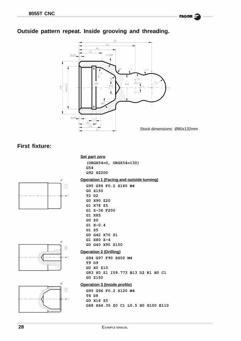
Outside pattern repeat. Inside grooving and threading.
First fixture:
Set part zero
(ORGX54=0, ORGZ54=130)G54G92 S2200
Operation 1 (Facing and outside turning)
G95 G96 F0.2 S180 M4G0 Z150T2 D2G0 X90 Z20G1 X78 Z5G1 Z-36 F200G1 X85G0 Z0G1 X-0.4G1 Z5G0 G42 X70 Z1G1 X80 Z-4G0 G40 X90 Z150
Operation 2 (Drilling)
G94 G97 F90 S600 M4T9 D9G0 X0 Z10G83 X0 Z1 I59.773 B13 D2 K1 H0 C1G0 Z150
Operation 3 (Inside profile)
G95 G96 F0.2 S120 M4T8 D8G0 X16 Z5G68 X64.35 Z0 C1 L0.5 H0 S100 E110
Stock dimensions: Ø80x132mm

EXAMPLE MANUAL 29
8055T CNC
G0 G41 X65.35 Z0.5N100 G1 G5 X58.35 Z-3G1 G36 R13 X58.35 Z-32G1 G36 R6 X25.4024 Z-54N110 G1 X18 Z-54G0 G40 G7 Z150
Operation 4 (Inside grooving)
G95 G96 F0.08 S50 M4T13 D13G0 G41 X40 Z-15G88 X60 Z-19 Q62 R-25 K5G0 Z150
Operation 5 (Inside threading)
G95 G96 F0.15 S60 M4T10 D10G0 X40 Z1.5G86 X60 Z0 Q60 R-20 I-0.8 B0.4 D-2 L0 C1.5 J0 A29.5G0 Z150
Second fixture:
Set new part zero
(MSG “* NEW FIXTURE - REVERSE PART *”)M0 M5(MSG “”)(ORGX54=0, ORGZ54=128)G54G92 S2200
Operation 6 (Outside profile roughing)
G95 G96 F0.2 S120 M4T2 D2G0 X85 Z5G68 X0 Z0 C1.5 L0.5 H0 S120 E130(GOTO N140)N120 G3 X42 Z-21 I0 K-21G1 X44 Z-45X44 Z-69.5X66 Z-73N130 X80 Z-94N140 G0 Z20
Operation 7 (Outside profile finishing)
G95 G96 F0.2 S120 M4G0 G90 X85 Z20G1 X85 Z5G66 X0 Z0 I2.5 C0.5 L0.2 H0.1 S150 E160(GOTO N170)N150 G5 G3 G36 R10 X33.56 Z-33.63 R21G3 G36 R10 X40 Z-52.48 R15G1 G36 R8 X40 Z-74X63.86 Z-74N160 G7 X78 Z-94N170 G90 G0 Z150M30

30 EXAMPLE MANUAL
8055T CNC
First fixture:
Set part zero
(ORGX54=0, ORGZ54=122)G54G92 S2200
Operation 1 (Facing and outside turning)
G95 G96 F0.2 S180 M4G0 Z150T2 D2G0 X90 Z20G1 X85 Z0X-0.4Z5G1 G42 X0 Z0G36 R5 X78 Z0Z-35X85G0 G40 X90 Z150
Second fixture:
Set new part zero
(MSG “* NEW FIXTURE - REVERSE PART *”)M0 M5(MSG “”)(ORGX54=0, ORGZ54=120)G54G92 S2200
Inside and outside roughing on the X axis
Stock dimensions: Ø80x124mm

EXAMPLE MANUAL 31
8055T CNC
Operation 2 (Outside profile turning)
G95 G96 F0.2 S180 M4T3 D3G0 X80 Z20G1 Z5G68 X0 Z0 C1 L0.5 H0.1 S100 E110(GOTO N120)N100 G1 G36 R5 X78 Z0Z-8G3 X40 Z-32 R92.74G1 Z-42G36 R5 X65 Z-49.39X40 Z-57N110 G2 X78 Z-90 R31N120 G0 Z150
Operation 3 (Drilling)
G94 G97 F90 S600 T9 M4G0 X0 Z10G83 X0 Z0 I35.773 B10 D2 H5 C2G0 Z150
Operation 4 (Inside profile turning)
G95 G96 F0.1 S120 M4T8 D8G0 X16 Z20G1 Z5G68 X58 Z0 C1 L0.5 H0.1 S150 E160(GOTO N170)N150 G3 X20 Z-30 R46.6N160 G1 X19N170 G1 Z20G0 X85 Z150M30

33
Programming examples:
«C» axis programming
8055T
Machining a profile in the ZC plane. .............................................................. 34
Machining a profile in the XC plane. .............................................................. 35

34 EXAMPLE MANUAL
8055T CNC
Machining a profile in the ZC plane.
Selecting the radial live tool.
G0 X100 Z150T15 D15M45 S-600
Operation 1 (Machining of the slot)
G15 R36 ............................................Select the "C" axis.G16 ZC ...............................................Select the work plane.G0 X90Z-15 C0G1 G94 X72 F100 M13Z-35G1 X90
Operation 2 (Grooving)
G15 R37G16 ZCG0 Z-50 C-125.664 .......................Position at point A.G1 X74 F100G91 C40 F50 ....................................Section A-B.Z-15 ...................................................Section B-C.C28 .....................................................Section C-D.Z15 C57.664 ....................................Section D-E.Z-15 C57.664 .................................. Section E-F.C28 .....................................................Section F-G.Z15 .....................................................Section G-H.C40 .....................................................Section H-A.G90 X90G0 Z10M30

EXAMPLE MANUAL 35
8055T CNC
Machining a profile in the XC plane.
Select the axial live tool.
G0 X100 Z150T16 D16M45 S600
Operation 1 (Machining of a hexagon)
G15 .....................................................Select the "C" axis.G16 XC ...............................................Select the work plane.G94 Z10 C0 F100G1 Z-6G1 G42 X39.26 C0 ......................... Position at point 1.X19.63 C34 ......................................Section 1-2.X-19.63 C34 ....................................Section 2-3.X-39.26 C0 ......................................Section 3-4.X-19.36 C-34 .................................. Section 4-5.X19.63 C-34 ....................................Section 5-6.X39.26 C0 ........................................ Section 6-1.G0 G40 X50Z10
Operation 2 (Making the grooves and the holes)
X23.492 C8.55G1 Z-5 F50G2 X23.492 C-8.55 R25 .............. Grooving A.G0 Z5X0 C-25 ............................................Position at point B.G1 Z-5G1 Z5G0 X-23.492 C-8.55G1 Z-5G2 X-23.492 C8.55 R25 .............. Grooving C.G0 Z5X0 C25 ...............................................Position at point D.G1 Z-5G0 Z5M30
37
Programming examples:
Profile Editor
8055T
Profile editor. Example 1. ............................................................................. 38
Profile editor. Example 2. ............................................................................. 39
Profile editor. Example 3. ............................................................................. 40
Profile editor. Example 4. ............................................................................. 41

38 EXAMPLE MANUAL
8055T CNC
Profile editor. Example 1.
PROFILE DEFINITION WITHOUT ROUNDINGS, CHAMFERS, TANGENTIAL ENTRY AND EXIT
• STARTING POINT : Z = 100 X = 0• STRAIGHT : Z = 80 X = 0
• STRAIGHT : Z = 80 X = 50
• STRAIGHT : Z = 60 X = 50
• CLOCKWISE ARC : Z = 40 X = 90 Radius = 20
• STRAIGHT : Z = 20 X = 90• STRAIGHT : Z = 20 X = 110
• STRAIGHT : Z = 0 X = 110
• STRAIGHT : Z = 0 X = 150
DEFINITION OF ROUNDINGS, CHAMFER TANGENTIAL ENTRY AND EXIT
Select the «MODIFY» option and define:
TANGENTIAL ENTRY........... Select point "1" .............. Press ENTER ....... Enter Radius = 5CHAMFER ........................... Select point "2" .............. Press ENTER ....... Enter Size = 10ROUNDING .......................... Select point "3" .............. Press ENTER ....... Enter Radius = 5ROUNDING .......................... Select point "4" .............. Press ENTER ....... Enter Radius = 5TANGENTIAL EXIT ............... Select point "5" .............. Press ENTER ....... Enter Radius = 5
Press ESC to quit the «Modify» option.
END OF EDITING
Select the softkeys: END + SAVE PROFILE. The CNC quits the profile editing mode and shows, in ISO code,the program that has been generated.

EXAMPLE MANUAL 39
8055T CNC
Profile editor. Example 2.
PROFILE DEFINITION
• STARTING POINT : Z= 170 X= 0• CCW ARC (1) : Zcenter= 140 Xcenter= 0 Radius= 30 Tangent= Yes• CCW ARC (2) : Radius= 350 Tangent= Yes• CW ARC (3) : Zcenter= 50 Xcenter= 190 Radius= 30 Tangent= Yes
The CNC shows all the possible options for section 2. Select the right one
• STRAIGHT LINE (4) : Z = 20 X = 220 Tangent= YesThe CNC shows all the possible options for sections 3-4. Select the right one
• STRAIGHT LINE (5) : Z = 0 X= 220
END OF EDITING
Select the softkeys: END + SAVE PROFILE. The CNC quits the profile editing mode and shows, in ISO code,the program that has been generated.

40 EXAMPLE MANUAL
8055T CNC
Profile editor. Example 3.
PROFILE DEFINITION
• STARTING POINT : Z = 180 X = 0• CCW ARC (1) : Zcenter= 150 Xcenter=0 Radius = 30• STRAIGHT LINE (2) : Angle= 195 Tangent = Yes
The CNC shows all the possible options between sections 1-2. Select the right one
• CW ARC (3) : Radius = 20 Tangent = Yes• STRAIGHT LINE (4) : Angle= 160 Tangent = Yes• CW ARC (5) : Z = 30 X = 80 Zcenter= 45 Xcenter= 80 Tangent= Yes
The CNC shows all the possible options between sections 4-5. Select the right oneThe CNC shows all the possible options for section 3. Select the right one
• STRAIGHT LINE (6) : Z = 30 X = 100• STRAIGHT LINE (7) : Z = 0 X = 100
END OF EDITING
Select the softkeys END + SAVE PROFILE. The CNC quits the profile editing mode and shows, in ISO code,the program that has been generated.
EXAMPLE MANUAL 41
8055T CNC
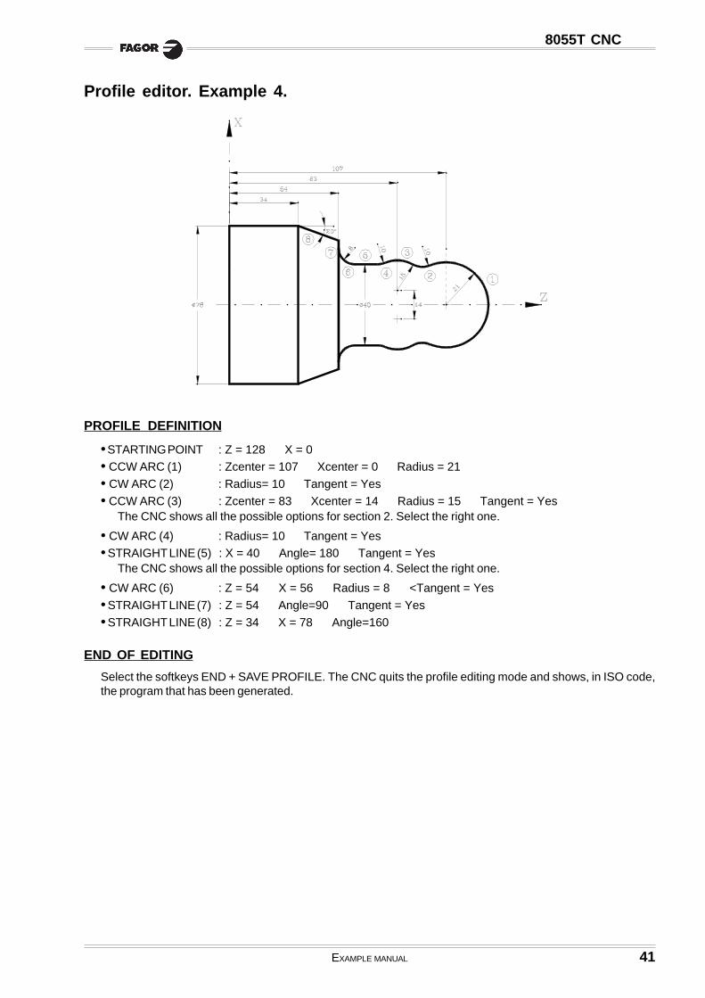
Profile editor. Example 4.
PROFILE DEFINITION
• STARTING POINT : Z = 128 X = 0• CCW ARC (1) : Zcenter = 107 Xcenter = 0 Radius = 21
• CW ARC (2) : Radius= 10 Tangent = Yes
• CCW ARC (3) : Zcenter = 83 Xcenter = 14 Radius = 15 Tangent = YesThe CNC shows all the possible options for section 2. Select the right one.
• CW ARC (4) : Radius= 10 Tangent = Yes• STRAIGHT LINE (5) : X = 40 Angle= 180 Tangent = Yes
The CNC shows all the possible options for section 4. Select the right one.
• CW ARC (6) : Z = 54 X = 56 Radius = 8 <Tangent = Yes
• STRAIGHT LINE (7) : Z = 54 Angle=90 Tangent = Yes
• STRAIGHT LINE (8) : Z = 34 X = 78 Angle=160
END OF EDITING
Select the softkeys END + SAVE PROFILE. The CNC quits the profile editing mode and shows, in ISO code,the program that has been generated.

43
Programming examples:
User screen customizing programs
8055T
Machine diagnosis. ...................................................................................... 44Machining a pulley. ...................................................................................... 52
44 EXAMPLE MANUAL
8055T CNC
Machine diagnosis.
This example shows:
a.- How to write a user screen customizing program.
In order to be able to execute this program in the user channel of the MANUAL mode, generalmachine parameter «USERMAN» must be set with the program number.
For better understanding, the explanation is divided into parts indicating the section of the program andthe creation of the corresponding screens (pages) and symbols. The different parts are:
- Part 1 : It requests the access code (password).- Part 2 : It shows the status of inputs I1 to I40.
(it uses user page 2 and the symbols 21 and 22)- Part 3 : It shows the status of outputs O1 to O18.
(It uses user page 3 and the symbols 21 and 22)- Part 4 : It shows the consumption of the motors.
(It uses user page 4 and the symbols 0 to 20)To go to the previous or next page, use the «previous page» and «next page» keys.
b.- How to create a user screen (page).
c.- How to create a user symbol.
Part 1: "Request password"
N100 (IB1= INPUT “PASSWORD = ”, 6) ...................... Requests the password(IF IB1 NE (123456) GOTO N100) .................... If the password is not correct (123456), it requests
it again.;N200 .................................................................................... If it is correct, the program continues on line
N200 (part 2)

EXAMPLE MANUAL 45
8055T CNC
Part 2: "Shows the status of inputs I1 through I40"
Program lines (main program).
N200 (PAGE2) .............................................. Shows page 2(KEY=0) .............................................. Clears the memory of the last key pressed.
N210 (P100=PLCI1) ................................... Assigns to parameter P100, the value of inputs I1 to I32(P199=85) .......................................... Row where to insert the symbol(CALL 2) ............................................ Call to subroutine (it inserts symbols)(P100=PLCI11) ................................. Assigns to parameter P100 the value of inputs I11 to I42(P199=155) ........................................ Row where to insert the symbol(CALL 2) ............................................ Call to subroutine (it inserts symbols)(P100=PLCI21) ................................. Assigns to parameter P100 the value of inputs I21 to I52(P199=225) ........................................ Row where to insert the symbol(CALL 2) ............................................ Row where to insert the symbol(P100=PLCI31) ................................. Asigna al parámetro P100 el valor de las entradas I31 a I62(P199=295) ........................................ Row where to insert the symbol(CALL 2) ............................................ Row where to insert the symbol(IF KEY EQ $FFAF GOTO N300) ... If “next page” has been pressed, it goes on to line N300 (part 3)(GOTO N210) ..................................... If not, refresh the status of the inputs.
Program lines (subroutine that indicates the status of a row of inputs).
This subroutine analyzes the 10 least significant bits of parameter P100. If the bit is set to «1», it insertssymbol 21 (lamp lit, red color) and if it is set to «0», it inserts symbol 22 (lamp off, background color).
Call parameters:- P100 = Value of the inputs to be displayed.- P199 = Row where the symbols are to be inserted.
(SUB 2)(IF (P100 AND 1) EQ 0 SYMBOL 22,80,P199 ELSE SYMBOL 21,80,P199)(IF (P100 AND 2) EQ 0 SYMBOL 22,130,P199 ELSE SYMBOL 21,130,P199)(IF (P100 AND 4) EQ 0 SYMBOL 22,180,P199 ELSE SYMBOL 21,180,P199)(IF (P100 AND 8) EQ 0 SYMBOL 22,230,P199 ELSE SYMBOL 21,230,P199)(IF (P100 AND $10) EQ 0 SYMBOL 22,280,P199 ELSE SYMBOL 21,280,P199)(IF (P100 AND $20) EQ 0 SYMBOL 22,330,P199 ELSE SYMBOL 21,330,P199)(IF (P100 AND $40) EQ 0 SYMBOL 22,380,P199 ELSE SYMBOL 21,380,P199)(IF (P100 AND $80) EQ 0 SYMBOL 22,430,P199 ELSE SYMBOL 21,430,P199)(IF (P100 AND $100) EQ 0 SYMBOL 22,480,P199 ELSE SYMBOL 21,480,P199)(IF (P100 AND $200) EQ 0 SYMBOL 22,530,P199 ELSE SYMBOL 21,530,P199)
(RET)
Editing symbols 21 and 22.
Access the screen customizing mode and select: [Utilities] [Editor] [Symbol] (symbol number) [Enter]
Symbol 21 Symbol 22Background color: Navy blue Background color: Navy blueMain color: Red Main color: Navy blueLine: Fine solid Line: Fine solidFilled circle Filled circleCenter: X10 Y10 Center: X10 Y10Move to..: X10 Y15 Move to..: X10 Y15

46 EXAMPLE MANUAL
8055T CNC
Editing page 2
Access the screen customizing mode and select: [Utilities] [Edit] [Page] 2 [Enter]
Select background color: Navy blue
Edit the following texts:
Edit the following circles (unfilled) with white main color and line type: Fine solid.
rolocniaM eziS txeT noitisoP rolocniaM eziS txeT noitisoP rolocniaM eziS txeT noitisoP
etihW egraL STUPNI 622X 01Y etihW llamS 31I 081X 041Y etihW llamS 72I 083X 012Y
deR egraL STUPNI 422X 8Y etihW llamS 41I 032X 041Y etihW llamS 82I 034X 012Y
etihW llamS 1I 08X 07Y etihW llamS 51I 082X 041Y etihW llamS 92I 084X 012Y
etihW llamS 2I 031X 07Y etihW llamS 61I 033X 041Y etihW llamS 03I 035X 012Y
etihW llamS 3I 081X 07Y etihW llamS 71I 083X 041Y etihW llamS 13I 08X 082Y
etihW llamS 4I 032X 07Y etihW llamS 81I 034X 041Y etihW llamS 23I 031X 082Y
etihW llamS 5I 082X 07Y etihW llamS 91I 084X 041Y etihW llamS 33I 081X 082Y
etihW llamS 6I 033X 07Y etihW llamS 02I 035X 041Y etihW llamS 43I 032X 082Y
etihW llamS 7I 083X 07Y etihW llamS 12I 08X 012Y etihW llamS 53I 082X 082Y
etihW llamS 8I 034X 07Y etihW llamS 22I 031X 012Y etihW llamS 63I 033X 082Y
etihW llamS 9I 084X 07Y etihW llamS 32I 081X 012Y etihW llamS 73I 083X 082Y
etihW llamS 01I 035X 07Y etihW llamS 42I 032X 012Y etihW llamS 83I 034X 082Y
etihW llamS 11I 08X 041Y etihW llamS 52I 082X 012Y etihW llamS 93I 084X 082Y
etihW llamS 21I 031X 041Y etihW llamS 62I 033X 012Y etihW llamS 04I 035X 082Y
rolocniaM retneC ...otevoM rolocniaM retneC ...otevoM rolocniaM retneC ...otevoM
etihW 09X 59Y 09X 201Y etihW 092X 561Y 092X 271Y etihW 094X 532Y 094X 242Y
etihW 041X 59Y 041X 201Y etihW 043X 561Y 043X 271Y etihW 045X 532Y 045X 242Y
etihW 091X 59Y 091X 201Y etihW 093X 561Y 093X 271Y etihW 09X 503Y 09X 213Y
etihW 042X 59Y 042X 201Y etihW 044X 561Y 044X 271Y etihW 041X 503Y 041X 213Y
etihW 092X 59Y 092X 201Y etihW 094X 561Y 094X 271Y etihW 091X 503Y 091X 213Y
etihW 043X 59Y 043X 201Y etihW 045X 561Y 045X 271Y etihW 042X 503Y 042X 213Y
etihW 093X 59Y 093X 201Y etihW 09X 532Y 09X 242Y etihW 092X 503Y 092X 213Y
etihW 044X 59Y 044X 201Y etihW 041X 532Y 041X 242Y etihW 043X 503Y 043X 213Y
etihW 094X 59Y 094X 201Y etihW 091X 532Y 091X 242Y etihW 093X 503Y 093X 213Y
etihW 045X 59Y 045X 201Y etihW 042X 532Y 042X 242Y etihW 044X 503Y 044X 213Y
etihW 09X 561Y 09X 271Y etihW 092X 532Y 092X 242Y etihW 094X 503Y 094X 213Y
etihW 041X 561Y 041X 271Y etihW 043X 532Y 043X 242Y etihW 045X 503Y 045X 213Y
etihW 091X 561Y 091X 271Y etihW 093X 532Y 093X 242Y
etihW 042X 561Y 042X 271Y etihW 044X 532Y 044X 242Y

EXAMPLE MANUAL 47
8055T CNC
Part 3: "Shows the status of outputs O1 to O18"
Program lines (main program).
N300 (PAGE3) .............................................. Shows page 3(KEY = 0 ) ........................................ Clears memory of last key pressed
N310 (P100=PLCO1) ................................... Assigns to parameter P100 the value of the outputs O1 to O32(P199=85) .......................................... Row where to insert the symbol(CALL 3) ............................................ Call to subroutine (it inserts symbols)(P100=PLCO10) ................................. Assigns to parameter P100 the value of the outputs O10 to O41(P199=155) ........................................ Row where to insert the symbol(CALL 3) ............................................ Call to subroutine (it inserts symbols)(IF KEY EQ $FFA5 GOTO N200) ... If "previous page" has been pressed, it goes on to line N200
(part 2)(IF KEY EQ $FFAF GOTO N400) ... If "next page" has been pressed, it goes on to line N400
(part 4)(GOTO N310) ..................................... If not, it refreshes the status of the outputs
Program lines (subroutine that indicates the status of a row of outputs).
This subroutine analyzes the 10 least significant bits of parameter P100. If the bit is set to «1», it insertssymbol 21 (lamp on, red color), if it is set to «0», it inserts symbol 22 (lamp off. background color).
Call parameters:- P100 = Value of the outputs to be displayed.- P199 = Row where to insert the symbols.
(SUB 3)(IF (P100 AND 1) EQ 0 SYMBOL 22,105,P199 ELSE SYMBOL 21,105,P199)(IF (P100 AND 2) EQ 0 SYMBOL 22,155,P199 ELSE SYMBOL 21,155,P199)(IF (P100 AND 4) EQ 0 SYMBOL 22,205,P199 ELSE SYMBOL 21,205,P199)(IF (P100 AND 8) EQ 0 SYMBOL 22,255,P199 ELSE SYMBOL 21,255,P199)(IF (P100 AND $10) EQ 0 SYMBOL 22,305,P199 ELSE SYMBOL 21,305,P199)(IF (P100 AND $20) EQ 0 SYMBOL 22,355,P199 ELSE SYMBOL 21,355,P199)(IF (P100 AND $40) EQ 0 SYMBOL 22,405,P199 ELSE SYMBOL 21,405,P199)(IF (P100 AND $80) EQ 0 SYMBOL 22,455,P199 ELSE SYMBOL 21,455,P199)(IF (P100 AND $100) EQ 0 SYMBOL 22,505,P199 ELSE SYMBOL 21,505,P199)
(RET)

48 EXAMPLE MANUAL
8055T CNC
Editing page 3
Access the screen customizing mode and select: [Utilities] [Editor] [Page] 3 [Enter]
Select background color: Navy blue
Edit the following texts:
Edit the following circles (unfilled) with white main color and line type: Fine solid.
rolocniaM eziS txeT noitisoP rolocniaM eziS txeT noitisoP rolocniaM eziS txeT noitisoP
etihW egraL STUPTUO 532X 01Y etihW llamS 6O 553X 07Y etihW llamS 31O 552X 041Y
deR egraL STUPTUO 332X 8Y etihW llamS 7O 504X 07Y etihW llamS 41O 503X 041Y
etihW llamS 1O 501X 07Y etihW llamS 8O 554X 07Y etihW llamS 51O 553X 041Y
etihW llamS 2O 551X 07Y etihW llamS 9O 505X 07Y etihW llamS 61O 504X 041Y
etihW llamS 3O 502X 07Y etihW llamS 01O 501X 041Y etihW llamS 71O 554X 041Y
etihW llamS 4O 552X 07Y etihW llamS 11O 551X 041Y etihW llamS 81O 505X 041Y
etihW llamS 5O 503X 07Y etihW llamS 21O 502X 041Y
rolocniaM retneC ...otevoM rolocniaM retneC ...otevoM rolocniaM retneC ...otevoM
etihW 511X 59Y 511X 201Y etihW 514X 59Y 514X 201Y etihW 562X 561Y 562X 271Y
etihW 561X 59Y 561X 201Y etihW 564X 59Y 564X 201Y etihW 513X 561Y 513X 271Y
etihW 512X 59Y 512X 201Y etihW 515X 59Y 515X 201Y etihW 563X 561Y 563X 271Y
etihW 562X 59Y 562X 201Y etihW 511X 561Y 511X 271Y etihW 514X 561Y 514X 271Y
etihW 513X 59Y 513X 201Y etihW 561X 561Y 561X 271Y etihW 564X 561Y 564X 271Y
etihW 563X 59Y 563X 201Y etihW 512X 561Y 512X 271Y etihW 515X 561Y 515X 271Y

EXAMPLE MANUAL 49
8055T CNC
Part 4: "Shows the consumption of motors"
The speed drives have an analog output (0 to 10V) proportional to the current consumed by the motor.
In this example, the following connections have been made:- The X axis drive’s current output is connected to the analog input 1 of the CNC.- The Z axis drive’s current output is connected to the analog input 2 of the CNC.- The spindle (S) drive’s current output is connected to the analog input 3 of the CNC.
Therefore, variables "ANAI1”, “ANAI2” and “ANAI3” show the analog voltage corresponding to the currents of theX and Z axes and of the spindle S.
21 symbols (0-20) are used to display the value of the current, in increments corresponding to 0.5V.To select the right symbol each time, the formula: "ABS ROUND (ANAI1/0.5)" is applied. In other words, therounded-up absolute value of the result of the operation "ANAI1/0.5".
Program lines.
N400 (PAGE 4) ............................................ Shows page 4.(KEY = 0) .......................................... Clears memory of last key pressed.
N410 (SYMBOL ABS ROUND (ANAI1/0.5), 130, 120)(SYMBOL ABS ROUND (ANAI2/0.5), 130, 190)(SYMBOL ABS ROUND (ANAI3/0.5), 130, 260)(IF KEY EQ $FFA5 GOTO N300) ... If "previous page" has been pressed, it goes on to line N300
(part 3)(GOTO N410) ..................................... If not, it refreshes the motor consumption.
Editing symbols 0-20
Access the screen customizing mode and select: [Utilities] [Editor] [Symbol] (symbol number) [Enter]
ELGNATCERDELLIF ENILDILOSENIF
neerG wolleY deR yarG neerG wolleY deR
morF ot morF ot morF ot morF ot morF ot morF ot morF ot
0LOBMYS --- --- --- --- --- --- 0Y0X 03Y004X 0Y001X 03Y001X 0Y002X 03Y002X 0Y003X 03Y003X
1LOBMYS 0Y0X 03Y02X --- --- --- --- 0Y02X 03Y004X 0Y001X 03Y001X 0Y002X 03Y002X 0Y003X 03Y003X
2LOBMYS 0Y0X 03Y04X --- --- --- --- 0Y04X 03Y004X 0Y001X 03Y001X 0Y002X 03Y002X 0Y003X 03Y003X
3LOBMYS 0Y0X 03Y06X --- --- --- --- 0Y06X 03Y004X 0Y001X 03Y001X 0Y002X 03Y002X 0Y003X 03Y003X
4LOBMYS 0Y0X 03Y08X --- --- --- --- 0Y08X 03Y004X 0Y001X 03Y001X 0Y002X 03Y002X 0Y003X 03Y003X
5LOBMYS 0Y0X 03Y001X --- --- --- --- 0Y001X 03Y004X --- --- 0Y002X 03Y002X 0Y003X 03Y003X
6LOBMYS 0Y0X 03Y021X --- --- --- --- 0Y021X 03Y004X --- --- 0Y002X 03Y002X 0Y003X 03Y003X
7LOBMYS 0Y0X 03Y041X --- --- --- --- 0Y041X 03Y004X --- --- 0Y002X 03Y002X 0Y003X 03Y003X
8LOBMYS 0Y0X 03Y061X --- --- --- --- 0Y061X 03Y004X --- --- 0Y002X 03Y002X 0Y003X 03Y003X
9LOBMYS 0Y0X 03Y081X --- --- --- --- 0Y081X 03Y004X --- --- 0Y002X 03Y002X 0Y003X 03Y003X
01LOBMYS 0Y0X 03Y002X --- --- --- --- 0Y002X 03Y004X --- --- --- --- 0Y003X 03Y003X
11LOBMYS 0Y0X 03Y002X 0Y002X 03Y022X --- --- 0Y022X 03Y004X --- --- --- --- 0Y003X 03Y003X
21LOBMYS 0Y0X 03Y002X 0Y002X 03Y042X --- --- 0Y042X 03Y004X --- --- --- --- 0Y003X 03Y003X
31LOBMYS 0Y0X 03Y002X 0Y002X 03Y062X --- --- 0Y062X 03Y004X --- --- --- --- 0Y003X 03Y003X
41LOBMYS 0Y0X 03Y002X 0Y002X 03Y082X --- --- 0Y082X 03Y004X --- --- --- --- 0Y003X 03Y003X
51LOBMYS 0Y0X 03Y002X 0Y002X 03Y003X --- --- 0Y003X 03Y004X --- --- --- --- --- ---
61LOBMYS 0Y0X 03Y002X 0Y002X 03Y003X 0Y003X 03Y023X 0Y023X 03Y004X --- --- --- --- --- ---
71LOBMYS 0Y0X 03Y002X 0Y002X 03Y003X 0Y003X 03Y043X 0Y043X 03Y004X --- --- --- --- --- ---
81LOBMYS 0Y0X 03Y002X 0Y002X 03Y003X 0Y003X 03Y063X 0Y063X 03Y004X --- --- --- --- --- ---
91LOBMYS 0Y0X 03Y002X 0Y002X 03Y003X 0Y003X 03Y083X 0Y083X 03Y004X --- --- --- --- --- ---
02LOBMYS 0Y0X 03Y002X 0Y002X 03Y003X 0Y003X 03Y004X --- --- --- --- --- --- --- ---

50 EXAMPLE MANUAL
8055T CNC
Editing page 4
Access the screen customizing mode and select: [Utilities] [Editor] [Page] 4 [Enter]
Select background color: Navy blue
Edit the following texts:
Edit the following graphics elements with line type: Fine solid.
rolocniaM eziS txeT noitisoP rolocniaM eziS txeT noitisoP
etihW egraL NOITPMUSNOCROTOM 021X 01Y etihW egraL S 08X 352Y
deR egraL NOITPMUSNOCROTOM 811X 8Y etihW llamS %52 022X 08Y
etihW egraL X 08X 311Y etihW llamS %05 023X 08Y
etihW egraL Z 08X 381Y etihW llamS %57 024X 08Y
rolocniaM tnemelE renrocts1 renrocdn2 rolocniaM tnemelE dnets1 dnedn2
etihW elgnatceRdellifnU 921X 911Y 135X 151Y neerG enilsuounitnoC 032X 001Y 032X 013Y
etihW elgnatceRdellifnU 921X 981Y 135X 122Y wolleY enilsuounitnoC 033X 001Y 033X 013Y
etihW elgnatceRdellifnU 921X 952Y 135X 192Y deR enilsuounitnoC 034X 001Y 034X 013Y
EX
AM
PLE M
AN
UA
L51
8055T C
NC
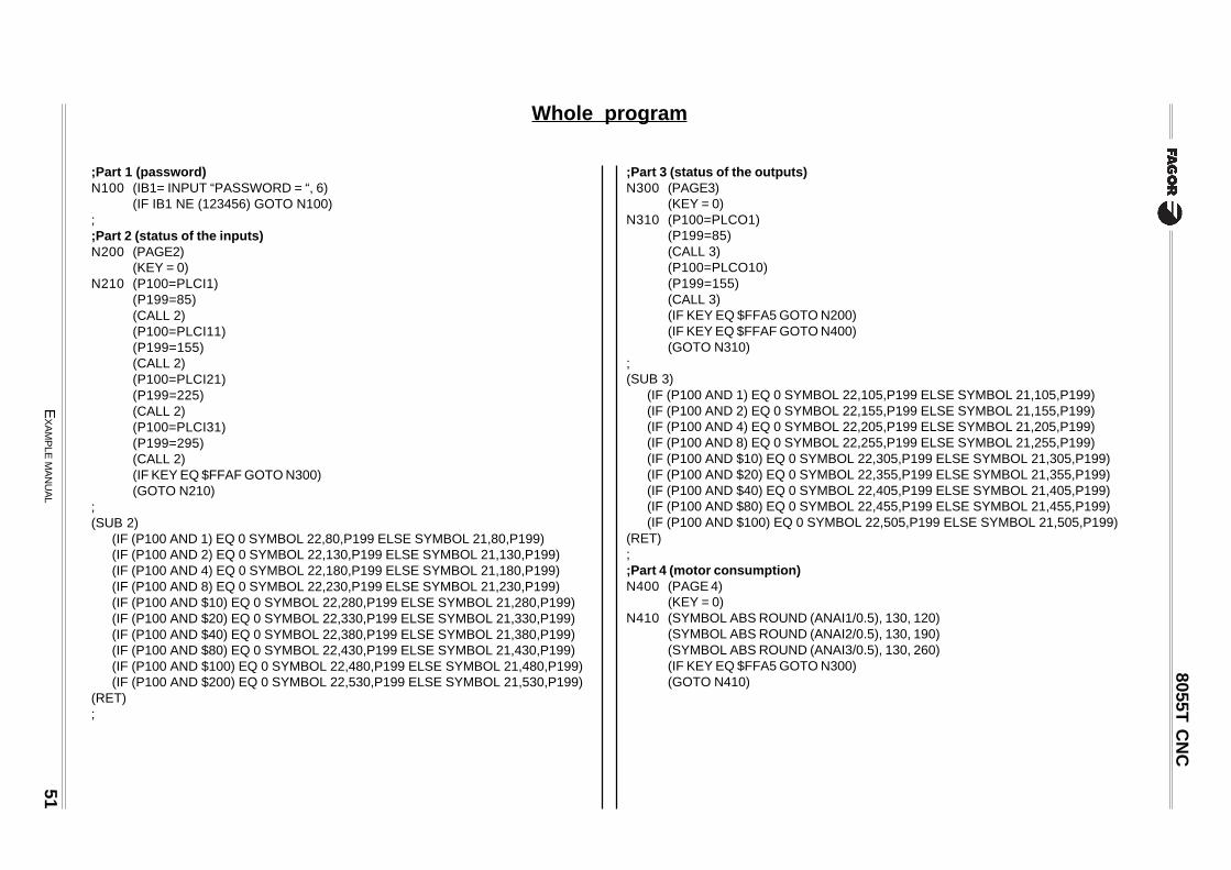
;Part 1 (password)N100 (IB1= INPUT “PASSWORD = “, 6)
(IF IB1 NE (123456) GOTO N100);;Part 2 (status of the inputs)N200 (PAGE2)
(KEY = 0)N210 (P100=PLCI1)
(P199=85)(CALL 2)(P100=PLCI11)(P199=155)(CALL 2)(P100=PLCI21)(P199=225)(CALL 2)(P100=PLCI31)(P199=295)(CALL 2)(IF KEY EQ $FFAF GOTO N300)(GOTO N210)
;(SUB 2)
(IF (P100 AND 1) EQ 0 SYMBOL 22,80,P199 ELSE SYMBOL 21,80,P199)(IF (P100 AND 2) EQ 0 SYMBOL 22,130,P199 ELSE SYMBOL 21,130,P199)(IF (P100 AND 4) EQ 0 SYMBOL 22,180,P199 ELSE SYMBOL 21,180,P199)(IF (P100 AND 8) EQ 0 SYMBOL 22,230,P199 ELSE SYMBOL 21,230,P199)(IF (P100 AND $10) EQ 0 SYMBOL 22,280,P199 ELSE SYMBOL 21,280,P199)(IF (P100 AND $20) EQ 0 SYMBOL 22,330,P199 ELSE SYMBOL 21,330,P199)(IF (P100 AND $40) EQ 0 SYMBOL 22,380,P199 ELSE SYMBOL 21,380,P199)(IF (P100 AND $80) EQ 0 SYMBOL 22,430,P199 ELSE SYMBOL 21,430,P199)(IF (P100 AND $100) EQ 0 SYMBOL 22,480,P199 ELSE SYMBOL 21,480,P199)(IF (P100 AND $200) EQ 0 SYMBOL 22,530,P199 ELSE SYMBOL 21,530,P199)
(RET);
;Part 3 (status of the outputs)N300 (PAGE3)
(KEY = 0)N310 (P100=PLCO1)
(P199=85)(CALL 3)(P100=PLCO10)(P199=155)(CALL 3)(IF KEY EQ $FFA5 GOTO N200)(IF KEY EQ $FFAF GOTO N400)(GOTO N310)
;(SUB 3)
(IF (P100 AND 1) EQ 0 SYMBOL 22,105,P199 ELSE SYMBOL 21,105,P199)(IF (P100 AND 2) EQ 0 SYMBOL 22,155,P199 ELSE SYMBOL 21,155,P199)(IF (P100 AND 4) EQ 0 SYMBOL 22,205,P199 ELSE SYMBOL 21,205,P199)(IF (P100 AND 8) EQ 0 SYMBOL 22,255,P199 ELSE SYMBOL 21,255,P199)(IF (P100 AND $10) EQ 0 SYMBOL 22,305,P199 ELSE SYMBOL 21,305,P199)(IF (P100 AND $20) EQ 0 SYMBOL 22,355,P199 ELSE SYMBOL 21,355,P199)(IF (P100 AND $40) EQ 0 SYMBOL 22,405,P199 ELSE SYMBOL 21,405,P199)(IF (P100 AND $80) EQ 0 SYMBOL 22,455,P199 ELSE SYMBOL 21,455,P199)(IF (P100 AND $100) EQ 0 SYMBOL 22,505,P199 ELSE SYMBOL 21,505,P199)
(RET);;Part 4 (motor consumption)N400 (PAGE 4)
(KEY = 0)N410 (SYMBOL ABS ROUND (ANAI1/0.5), 130, 120)
(SYMBOL ABS ROUND (ANAI2/0.5), 130, 190)(SYMBOL ABS ROUND (ANAI3/0.5), 130, 260)(IF KEY EQ $FFA5 GOTO N300)(GOTO N410)
Whole program

52 EXAMPLE MANUAL
8055T CNC
Machining a pulley.
This example shows:
a.- How to create a subroutine to execute the pulley .
In the example, the program contains the subroutine to execute the pulley (Subroutine 50).The dimensions of the pulley must be defined by the user before calling upon this subroutine.
b.- How to create a user screen customizing program.
In order to be able to execute this program in the user channel of the Editing mode, general machineparameter «USEREDIT» must be set with the program number.
Once all the data of the pulley have been defined, this program generates, in the program being edited,all the blocks necessary to execute the desired pulley.
c.- How to create a user screen (page).
This program uses page 50 which is the screen shown at the CNC when selecting the «User editor»option in the Editor Mode.

EXAMPLE MANUAL 53
8055T CNC
a=P107/cos(P100/2)b=P106∗tg(P100/2)c=(P103-P107)∗tg(P100/2)d=P104-2a-2ce=[(x/2)-((P102/2)-P103+P107)]∗tg(P100/2)
Pulley executing subroutine (Subroutine 50)
The tool data is:
D=12F=2NOSEA=90NOSEW=4CUTA=0Calibrated for the corner indicated by the arrow.
The Call parameters of the subroutine are:
P100 = Angle between the sides of the pulley.P101 = Absolute Z center coordinate of the pulley.P102 = Outside diameter of the pulley.P103 = Depth of the groove (in radius).P104 = Width of the groove.P105 = Safety distance.P106 = Maximum machining depth.P107 = Finishing stock.P108 = Cutting feedrate.P109 = Roughing feedrate in mm/rev.P110 = Finishing feedrate mm/rev.
The necessary points for the roughing operation are:
The necessary points for the finishing operation are:
X Z
A 501P2+201P ])2/001P(soc/701P[-)2/401P(+101P
B-A 501P2- 0
C-B 601P2- )2/001P(gt601P-
D-C 0 )e2+d(-
E-D 601P2- )2/001P(gt601P
F-E 0 e2+d
X Z
1 501P2+201P 101P
2 201P )2/401P(+101P
3 301P2-201P )2/001P(gt301P-)2/401P(+101P
4 301P2-201P )2/001P(gt301P+)2/401P(-101P
5 201P )2/401P(-101P
6 501P2+201P )2/401P(-101P

54 EXAMPLE MANUAL
8055T CNC
Program lines of the subroutine:
(SUB 50)(IF NOSEW12 GT (P104-2*(P107/COS(P100/2))- 2*(P103-P107)*TAN(P100/2)) ERROR “WRONG DATA”) ............................ If cutter width > "d" => Error;———————————————————————————————————————————————————————————————; Roughing operation;———————————————————————————————————————————————————————————————(P115=FUP((P103-P107)/P106)) ...................................................................... Calculates Nr. of passes (P115).(P106=(P103-P107)/P115) ................................................................................ Recalculates the pass (P106).G92 S500G95 G96 FP109 SP108 T12 M4 M41;(P1=P102+2*P105, P2=P101+(P104/2)-(P107/COS(P100/2))-NOSEW12)G G90 XP1 ZP2 ..................................................................................................... Move to point "A"(P1=2*P105)G1 G91 X-P1 ......................................................................................................... Movement "A-B"N50 (P1=2*P106, P2=P106*TAN(P100/2))
X-P1 Z-P2 ...................................................................................................... Movement "B-C"(P2=P104-2*P107/COS(P100/2)-2*(P103-P107)*TAN(P100/2)+ 2*(PPOSX/2-(P102/2-P103+P107))*TAN(P100/2)-NOSEW12)Z-P2 ................................................................................................................ Movement "C-D"(P115=P115-1) ............................................................................................. Counts down Nr. of passes(IF P115 LE 0 GOTO N100) ...................................................................... If done with all roughing passes,
go to finishing stage.(P1=2*P106, P2=P106*TAN(P100/2))X-P1 ZP2 ........................................................................................................ Movement "D-E"(P2=P104-2*(P107/COS(P100/2))-2*(P103-P107)*TAN(P100/2)+ 2*(PPOSX/2-(P102/2-P103+P107))*TAN(P100/2)-NOSEW12)ZP2 .................................................................................................................. Movement "E-F"(P115=P115-1) ............................................................................................. Counts down Nr. of passes(IF P115 GT 0 GOTO N50) ........................................................................ If done with all roughing passes,
go to finishing stage.;———————————————————————————————————————————————————————————————; Roughing operation;———————————————————————————————————————————————————————————————N100 G95 G96 FP110 SP108
(P1=P102+2*P105)G0 G90 XP1 ZP101 ....................................................................... Movement to point "1"(P2=P101+(P104/2)-NOSEW12)G1 XP102 ZP2 ............................................................................... Movement to point "2"(P1=P102-2*P103)(P2=P101+(P104/2)-P103*TAN(P100/2)-NOSEW12)XP1 ZP2 .......................................................................................... Movement to point "3"(P1=P102-2*P103)(P2=P101-(P104/2)+P103*TAN(P100/2))XP1 ZP2 .......................................................................................... Movement to point "4"(P2=P101-(P104/2))XP102 ZP2 ...................................................................................... Movement to point "5"(P1=P102+2*P105, P2=P101-(P104/2))XP1Z P2 .......................................................................................... Movement to point "6"(P1=P102+2*P105)XP1 ZP101 ...................................................................................... Movement to point "1"
(RET)

EXAMPLE MANUAL 55
8055T CNC
Editing page 50.
Access the screen customizing mode and select: [Utilities] [Editor] [Page] 50 [Enter]
Select background color: Navy blue.
Edit the following graphic elements:
Edit the following texts:
tnemelE rolocniaM epyteniL renrocts1 renrocdn2 tnemelE rolocniaM epyteniL renrocts1 renrocdn2
enilyloP neergthgiL diloskcihT
52X 051Y 001X 051Y eniL etihW diloS 061X 001Y 592X 001Y
041X 042Y 081X 042Y eniL etihW diloS 572X 051Y 572X 052Y
022X 051Y 592X 051Y eniL etihW diloS 57X 042Y 531X 042Y
eniL etihW dehsaD 52X 041Y 592X 041Y eniL etihW diloS 08X 051Y 08X 042Y
eniL etihW dehsad-toD 061X 09Y 061X 062Y eniL etihW diloS 001X 541Y 001X 511Y
crA etihW diloS031X 5.712Y 091X 5.712Y eniL etihW diloS 022X 541Y 022X 511Y
...otevoM 061X 012Y eniL etihW diloS 001X 021Y 022X 021Y
eniL etihW diloS 53X 561Y 53X 021Y
rolocniaM eziS txeT noitisoP rolocniaM eziS txeT noitisoP
etihW egraL SYELLUPFOGNINIHCAM 78X 01Y eulbthgiL llamS etanidroocretnecZ.sbA101P 033X 211Y
deR egraL SYELLUPFOGNINIHCAM 58X 8Y eulbthgiL llamS retemaidedistuO201P 033X 441Y
etihW llamS 001P 261X 491Y eulbthgiL llamS evoorgehtfohtpeD301P 033X 061Y
etihW llamS 101P 012X 08Y eulbthgiL llamS evoorgehtfohtdiW401P 033X 671Y
etihW llamS 201P 082X 091Y eulbthgiL llamS ecnatsidytefaS501P 033X 802Y
etihW llamS 301P 48X 002Y eulbthgiL llamS peedgninihcam.xaM601P 033X 422Y
etihW llamS 401P 511X 001Y eulbthgiL llamS kcotsgnihsiniF701P 033X 042Y
etihW llamS 501P 04X 021Y eulbthgiL llamS deepsgnittuC801P 033X 272Y
etihW llamS SRETEMARAPELCYCDENNAC 063X 69Y eulbthgiL llamS etardeefgnihguoR901P 033X 882Y
eulbthgiL llamS sedisneewtebelgnA001P 033X 69Y eulbthgiL llamS etardeefgnihsiniF011P 033X 403Y
56E
XA
MP
LE MA
NU
AL
8055T C
NC
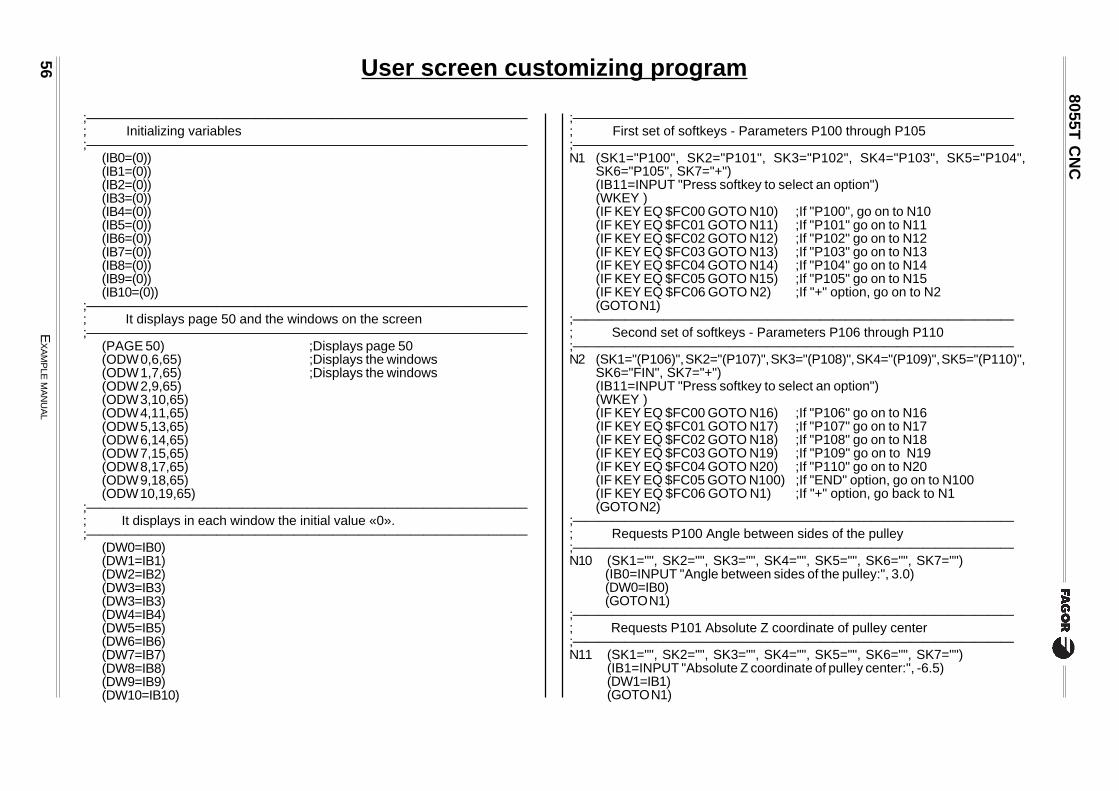
User screen customizing program
;——————————————————————————————————; Initializing variables;——————————————————————————————————
(IB0=(0))(IB1=(0))(IB2=(0))(IB3=(0))(IB4=(0))(IB5=(0))(IB6=(0))(IB7=(0))(IB8=(0))(IB9=(0))(IB10=(0))
;——————————————————————————————————; It displays page 50 and the windows on the screen;——————————————————————————————————
(PAGE 50) ;Displays page 50(ODW 0,6,65) ;Displays the windows(ODW 1,7,65) ;Displays the windows(ODW 2,9,65)(ODW 3,10,65)(ODW 4,11,65)(ODW 5,13,65)(ODW 6,14,65)(ODW 7,15,65)(ODW 8,17,65)(ODW 9,18,65)(ODW 10,19,65)
;——————————————————————————————————; It displays in each window the initial value «0».;——————————————————————————————————
(DW0=IB0)(DW1=IB1)(DW2=IB2)(DW3=IB3)(DW3=IB3)(DW4=IB4)(DW5=IB5)(DW6=IB6)(DW7=IB7)(DW8=IB8)(DW9=IB9)(DW10=IB10)
;——————————————————————————————————; First set of softkeys - Parameters P100 through P105;——————————————————————————————————N1 (SK1="P100", SK2="P101", SK3="P102", SK4="P103", SK5="P104",
SK6="P105", SK7="+")(IB11=INPUT "Press softkey to select an option")(WKEY )(IF KEY EQ $FC00 GOTO N10) ;If "P100", go on to N10(IF KEY EQ $FC01 GOTO N11) ;If "P101" go on to N11(IF KEY EQ $FC02 GOTO N12) ;If "P102" go on to N12(IF KEY EQ $FC03 GOTO N13) ;If "P103" go on to N13(IF KEY EQ $FC04 GOTO N14) ;If "P104" go on to N14(IF KEY EQ $FC05 GOTO N15) ;If "P105" go on to N15(IF KEY EQ $FC06 GOTO N2) ;If "+" option, go on to N2(GOTO N1)
;——————————————————————————————————; Second set of softkeys - Parameters P106 through P110;——————————————————————————————————N2 (SK1="(P106)", SK2="(P107)", SK3="(P108)", SK4="(P109)", SK5="(P110)",
SK6="FIN", SK7="+")(IB11=INPUT "Press softkey to select an option")(WKEY )(IF KEY EQ $FC00 GOTO N16) ;If "P106" go on to N16(IF KEY EQ $FC01 GOTO N17) ;If "P107" go on to N17(IF KEY EQ $FC02 GOTO N18) ;If "P108" go on to N18(IF KEY EQ $FC03 GOTO N19) ;If "P109" go on to N19(IF KEY EQ $FC04 GOTO N20) ;If "P110" go on to N20(IF KEY EQ $FC05 GOTO N100) ;If "END" option, go on to N100(IF KEY EQ $FC06 GOTO N1) ;If "+" option, go back to N1(GOTO N2)
;——————————————————————————————————; Requests P100 Angle between sides of the pulley;——————————————————————————————————N10 (SK1="", SK2="", SK3="", SK4="", SK5="", SK6="", SK7="")
(IB0=INPUT "Angle between sides of the pulley:", 3.0)(DW0=IB0)(GOTO N1)
;——————————————————————————————————; Requests P101 Absolute Z coordinate of pulley center;——————————————————————————————————N11 (SK1="", SK2="", SK3="", SK4="", SK5="", SK6="", SK7="")
(IB1=INPUT "Absolute Z coordinate of pulley center:", -6.5)(DW1=IB1)(GOTO N1)

EX
AM
PLE M
AN
UA
L57
8055T C
NC
;——————————————————————————————————; Requests P102 Outside diameter of the pulley;——————————————————————————————————N12 (SK1="", SK2="", SK3="", SK4="", SK5="", SK6="", SK7="")
(IB2=INPUT "Outside diameter of the pulley:", 6.5)(DW2=IB2)(GOTO N1)
;——————————————————————————————————; Requests P103 Depth of the pulley (in radius);——————————————————————————————————N13 (SK1="", SK2="", SK3="", SK4="", SK5="", SK6="", SK7="")
(IB3=INPUT "Depth of the groove (in radius):", 6.5)(DW3=IB3)(GOTO N1)
;——————————————————————————————————; Requests P104 Width of the groove;——————————————————————————————————N14 (SK1="", SK2="", SK3="", SK4="", SK5="", SK6="", SK7="")
(IB4=INPUT "Width of the groove:", 6.5)(DW4=IB4)(GOTO N1)
;——————————————————————————————————; Requests P105 Safety distance;——————————————————————————————————N15 (SK1="", SK2="", SK3="", SK4="", SK5="", SK6="", SK7="")
(IB5=INPUT "Safety distance:", 6.5)(DW5=IB5)(GOTO N1)
;——————————————————————————————————; Requests P106 Maximum cutting pass;——————————————————————————————————N16 (SK1="", SK2="", SK3="", SK4="", SK5="", SK6="", SK7="")
(IB6=INPUT "Maximum cutting pass:", 6.5)(DW6=IB6)(GOTO N2)
;——————————————————————————————————; Requests P107 Finishing stock;——————————————————————————————————N17 (SK1="", SK2="", SK3="", SK4="", SK5="", SK6="", SK7="")
(IB7=INPUT "Finishing stock:", 6.5)(DW7=IB7)(GOTO N2)
;——————————————————————————————————; Requests P108 Cutting speed;——————————————————————————————————N18 (SK1="", SK2="", SK3="", SK4="", SK5="", SK6="", SK7="")
(IB8=INPUT "Cutting speed:", 3.5)(DW8=IB8)(GOTO N2)
;——————————————————————————————————; Requests P109 Roughing feedrate in mm/rev.;——————————————————————————————————N19 (SK1="", SK2="", SK3="", SK4="", SK5="", SK6="", SK7="")
(IB9=INPUT "Roughing feedrate in mm/rev.:", 6.5)(DW9=IB9)(GOTO N2)
;——————————————————————————————————; Requests P110 Finishing feedrate in mm/rev.;——————————————————————————————————N20 (SK1="", SK2="", SK3="", SK4="", SK5="", SK6="", SK7="")
(IB10=INPUT "Finishing feedrate in mm/rev.:", 6.5)(DW10=IB10)(GOTO N2)
;——————————————————————————————————; Generates program blocks;——————————————————————————————————N100 (WBUF "(PCALL 50, P100=",IB0)
(WBUF ", P101=",IB1)(WBUF ", P102=",IB2)(WBUF ", P103=",IB3)(WBUF ", P104=",IB4)(WBUF ", P105=",IB5)(WBUF ", P106=",IB6)(WBUF ", P107=",IB7)(WBUF ", P108=",IB8)(WBUF ", P109=",IB9)(WBUF ", P110=",IB10)(WBUF ")")(WBUF )(SYSTEM )

![Retrospective Cohort Study Absolute monocyte and lymphocyte count … · platelet volume (MPV)[8], absolute neutrophil count (ANC) [9], absolute monocyte counts (AMC) , absolute lymphocyte](https://img.pdfslide.net/doc/110x75/5ea05036c63dd366f76addb5/retrospective-cohort-study-absolute-monocyte-and-lymphocyte-count-platelet-volume.jpg)