Embed Size (px)
Citation preview
Condensation Risk Assessment
in Glazing Design
A condensation risk assessment on building enclosure details can be used to gather information on potential condensate formation, suggesting ways to improve design. These evaluations indicate whether water
condensation will form within a particular construction detail, providing the average design conditions listed in the specifi cations are met.
In the assessment, a thermal simulation yields a ‘worst-case’ temperature map that can be compared with the dewpoints obtained by water vapor pressure analysis. The process may involve one or more iterations to verify subsequent design modifi cations.
Condensation forms when the temperature of the analyzed layer is at or below the dewpoint temperature. For simplicity’s sake, only two extreme cases are analyzed: winter conditions for heated spaces and summer conditions for cooled spaces. Typically, the primary concern of the winter analysis is thermal insulation. The primary concern of the summer analysis, on the other hand, is the air seal and the adequacy of a mechanical system.
As the overall quality of construction increases, issues once regarded as marginal begin to surface. One of these is the ‘pure’ condensation primarily caused by diffusion, as opposed to air leakage. A glazing design typically provides a suffi cient air seal to postpone leak-related concerns until the construction phase.
This article deals exclusively with winter condensation. Summer condensation seldom presents a problem because the condensation forming on the exterior surface is managed by the same means as rainwater. However, winter condensation forming on interior surfaces is much tougher to control.
Are condensation risk assessments necessary?As long as it does not create conditions for accelerated deterioration from moisture, condensation can be acceptable. In other words, the belt of water droplets occasionally appearing on the edge of a glass pane may be a visual annoyance, but provided the condensate is temporary in nature (i.e. it stays limited to its original location before entirely evaporating), it is not a critical failure.
by Karol Kazmierczak, CSI, CDT, AIA, ASHRAE, LEED AP
94 The Construction Specifi er November 2007
©Im
age
fro
m B
igSt
ock
Pho
to.c
om
CS-Nov07-a.indd 94CS-Nov07-a.indd 94 10/11/07 3:00:19 PM10/11/07 3:00:19 PM
November 2007 The Construction Specifi er 95
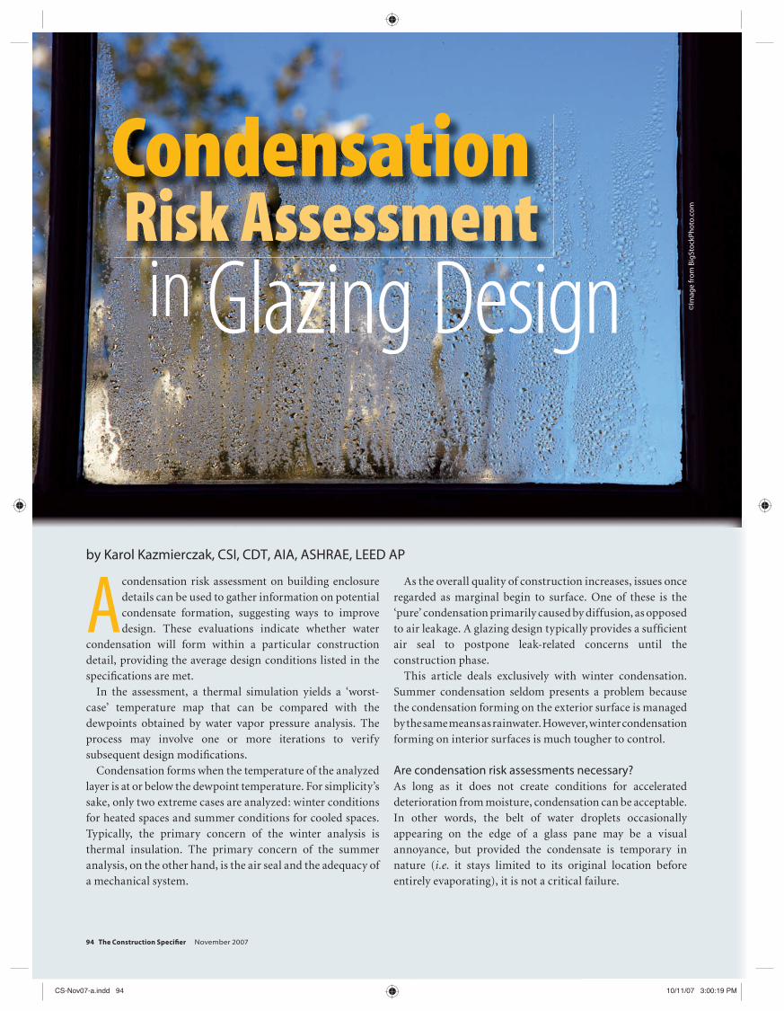
In Figure 1, condensation is forming on glass and its frame. Adjacent materials (i.e. metal, glass, and rubber) should be water-resistant. Consequently, there is an emphasis on ventilation. Curtain wall designers often look to drainage as a primary means to ensure the condensate (or its freezing) does not damage adjacent materials sensitive to moisture; the additional benefi t is increased control of incidental rainwater leakage.
Whether a condensation analysis is necessary depends on the project. A sound design following the principles of building envelope creation may not need a detailed condensation risk assessment. Unfortunately, as it happens, most designs violate the rules of continuity along with the descending permeability of façade layers.
ContinuityThe principle of continuity says the elements performing essential functions must be kept continuous throughout an enclosure, no matter which vertical or horizontal section of building envelope is analyzed. A discontinuity causes a functional failure. The typical example is a misalignment of the thermal insulation layer resulting in an increased risk of
condensation at the offset area. The area of misalignment frequently happens to contain highly conductive bridging elements (e.g. metal studs).
The solution is simple, but the execution is diffi cult: keep the layers continuous. A good façade consultant should be able to explain available technology and draw alternative
➤ Figure 1
Condensation formation on glass and frame.
Imag
es c
ou
rtes
y Ka
rol K
azm
ierc
zak
Interested in Writing
A Strategic Partner of
1-888-BSD-SOFT 1-888-273-7638Visit our website: www.bsdsoftlink.com
is the only comprehensive guide spec system with:
● Automated tools for simplifying LEED certification● Two intelligent checklists that activate green sections
and select relevant provisions● Built-in assistance for LEED-NC, LEED-CS, LEED-CI,
and LEED-EB● Green building provisions added to dozens of
technical sections● LEED submittal requirements in relevant sections● Automatic LEED submittals report
CSI_House_5x_H2.indd 5 9/14/07 9:33:51 AM
CS-Nov07-a.indd 95CS-Nov07-a.indd 95 10/11/07 3:00:24 PM10/11/07 3:00:24 PM
96 The Construction Specifi er November 2007
solution details of the seemingly inevitable penetrations, offsets, and misalignments.
Descending permeabilityThe principle of descending permeability says the layers forming the enclosure must be placed in order of their permeability—from highest to lowest, starting on the colder side of the partition. In other words, a properly layered assembly should allow moisture to evaporate by the same means it lets the moisture in: the pressure differential.
A hermetic assembly is an overused exception to this rule, frequently defeated by the reality of a construction site. Even insulated glass units (IGUs), which are manufactured under a strict quality regime otherwise unachievable in a fi eld, start
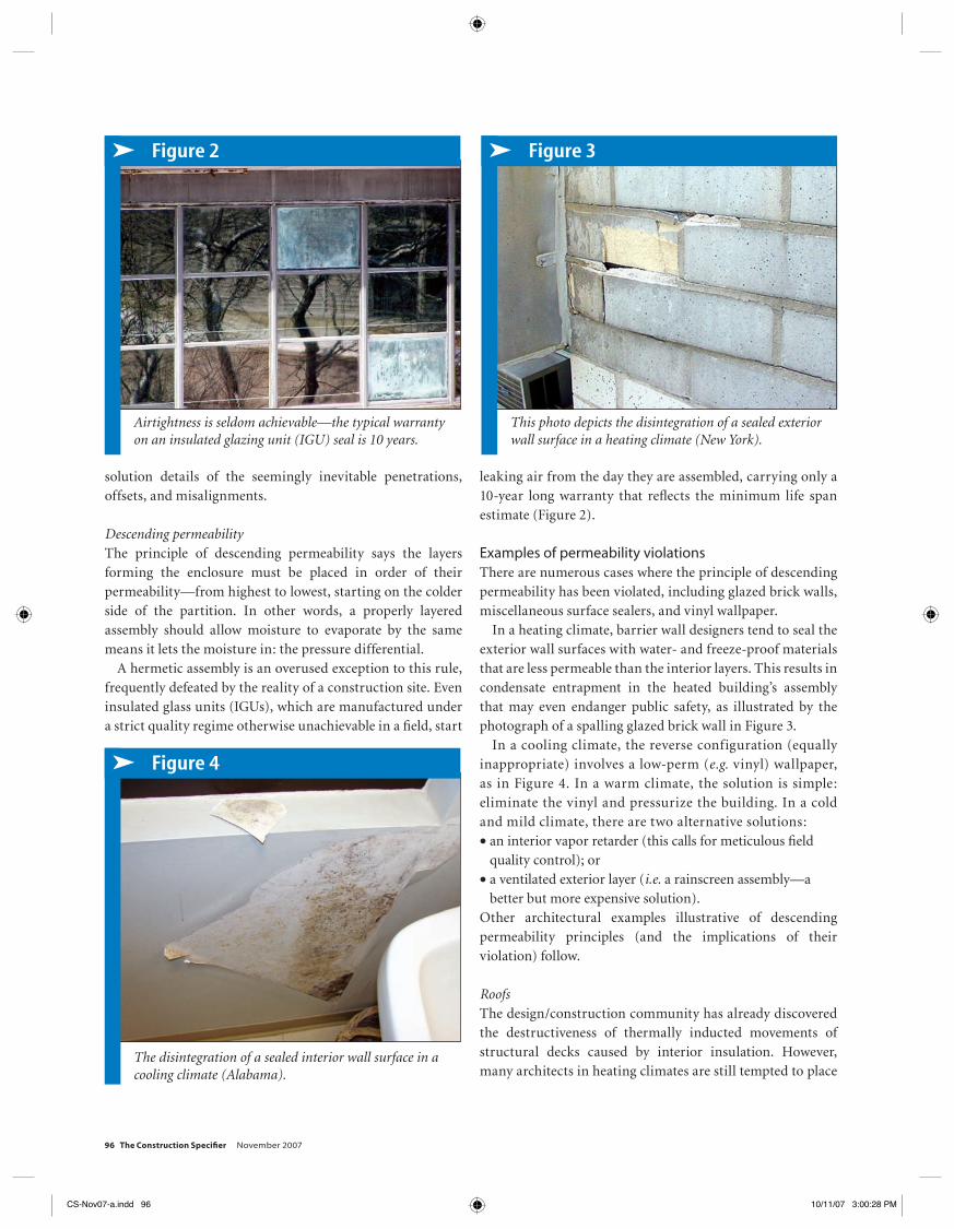
leaking air from the day they are assembled, carrying only a 10-year long warranty that refl ects the minimum life span estimate (Figure 2).
Examples of permeability violationsThere are numerous cases where the principle of descending permeability has been violated, including glazed brick walls, miscellaneous surface sealers, and vinyl wallpaper.
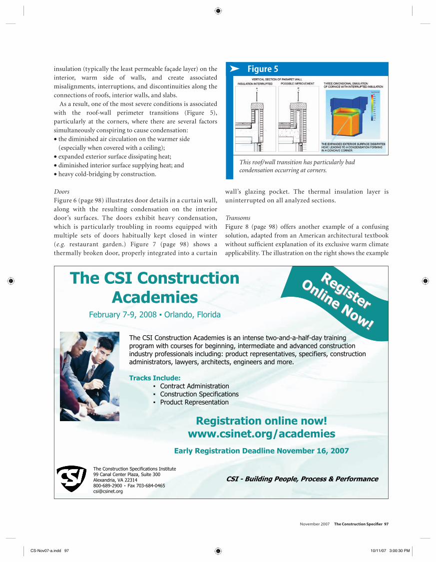
In a heating climate, barrier wall designers tend to seal the exterior wall surfaces with water- and freeze-proof materials that are less permeable than the interior layers. This results in condensate entrapment in the heated building’s assembly that may even endanger public safety, as illustrated by the photograph of a spalling glazed brick wall in Figure 3.
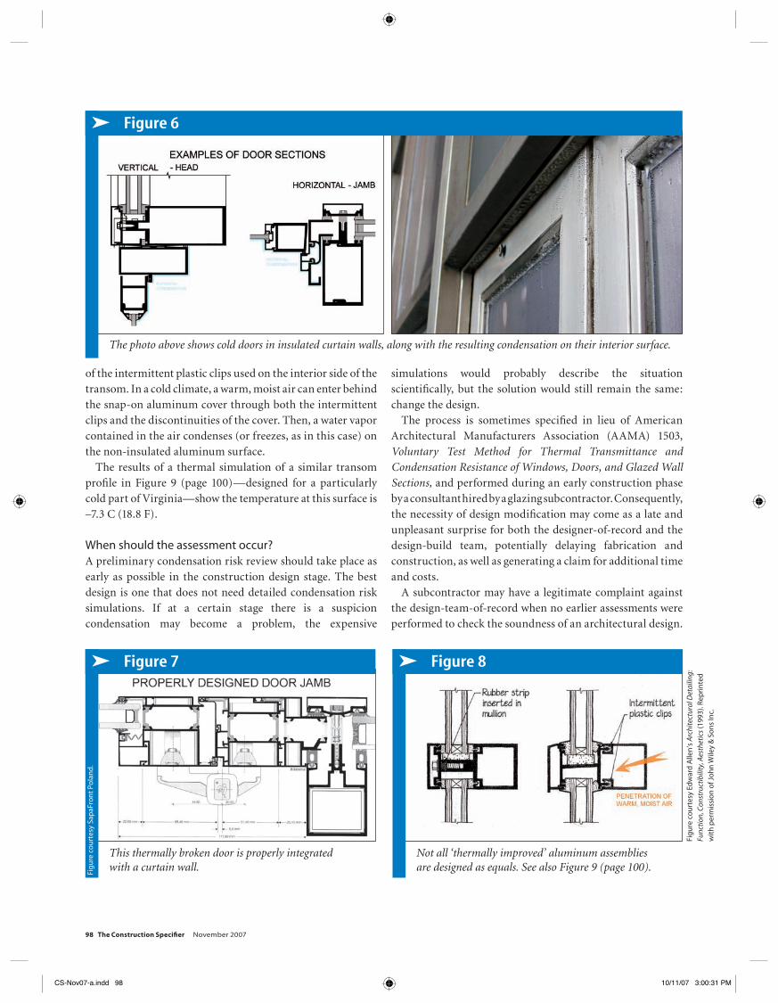
In a cooling climate, the reverse configuration (equally inappropriate) involves a low-perm (e.g. vinyl) wallpaper, as in Figure 4. In a warm climate, the solution is simple: eliminate the vinyl and pressurize the building. In a cold and mild climate, there are two alternative solutions:• an interior vapor retarder (this calls for meticulous fi eld
quality control); or• a ventilated exterior layer (i.e. a rainscreen assembly—a
better but more expensive solution).Other architectural examples illustrative of descending permeability principles (and the implications of their violation) follow.
RoofsThe design/construction community has already discovered the destructiveness of thermally inducted movements of structural decks caused by interior insulation. However, many architects in heating climates are still tempted to place
➤ Figure 2
Airtightness is seldom achievable—the typical warranty on an insulated glazing unit (IGU) seal is 10 years.
➤ Figure 3
This photo depicts the disintegration of a sealed exterior wall surface in a heating climate (New York).
➤ Figure 4
The disintegration of a sealed interior wall surface in a cooling climate (Alabama).
CS-Nov07-a.indd 96CS-Nov07-a.indd 96 10/11/07 3:00:28 PM10/11/07 3:00:28 PM
November 2007 The Construction Specifi er 97
insulation (typically the least permeable façade layer) on the interior, warm side of walls, and create associated misalignments, interruptions, and discontinuities along the connections of roofs, interior walls, and slabs.
As a result, one of the most severe conditions is associated with the roof-wall perimeter transitions (Figure 5), particularly at the corners, where there are several factors simultaneously conspiring to cause condensation:• the diminished air circulation on the warmer side
(especially when covered with a ceiling);• expanded exterior surface dissipating heat;• diminished interior surface supplying heat; and• heavy cold-bridging by construction.
DoorsFigure 6 (page 98) illustrates door details in a curtain wall, along with the resulting condensation on the interior door’s surfaces. The doors exhibit heavy condensation, which is particularly troubling in rooms equipped with multiple sets of doors habitually kept closed in winter (e.g. restaurant garden.) Figure 7 (page 98) shows a thermally broken door, properly integrated into a curtain
wall’s glazing pocket. The thermal insulation layer is uninterrupted on all analyzed sections.
TransomsFigure 8 (page 98) offers another example of a confusing solution, adapted from an American architectural textbook without suffi cient explanation of its exclusive warm climate applicability. The illustration on the right shows the example
➤ Figure 5
This roof/wall transition has particularly bad condensation occurring at corners.
The CSI Construction Academies is an intense two-and-a-half-day training program with courses for beginning, intermediate and advanced construction industry professionals including: product representatives, specifiers, construction administrators, lawyers, architects, engineers and more.
Tracks Include: Contract Administration Construction Specifications Product Representation
Registration online now! www.csinet.org/academies
Early Registration Deadline November 16, 2007
The CSI Construction Academies
February 7-9, 2008 Orlando, Florida
The Construction Specifications Institute 99 Canal Center Plaza, Suite 300 Alexandria, VA 22314 800-689-2900 Fax 703-684-0465 [email protected]
CSI - Building People, Process & Performance
Register
RegisterOnline Now!
Online Now!
Academies_2H.indd 1 10/11/07 9:03:56 AM
CS-Nov07-a.indd 97CS-Nov07-a.indd 97 10/11/07 3:00:30 PM10/11/07 3:00:30 PM
98 The Construction Specifi er November 2007
of the intermittent plastic clips used on the interior side of the transom. In a cold climate, a warm, moist air can enter behind the snap-on aluminum cover through both the intermittent clips and the discontinuities of the cover. Then, a water vapor contained in the air condenses (or freezes, as in this case) on the non-insulated aluminum surface.
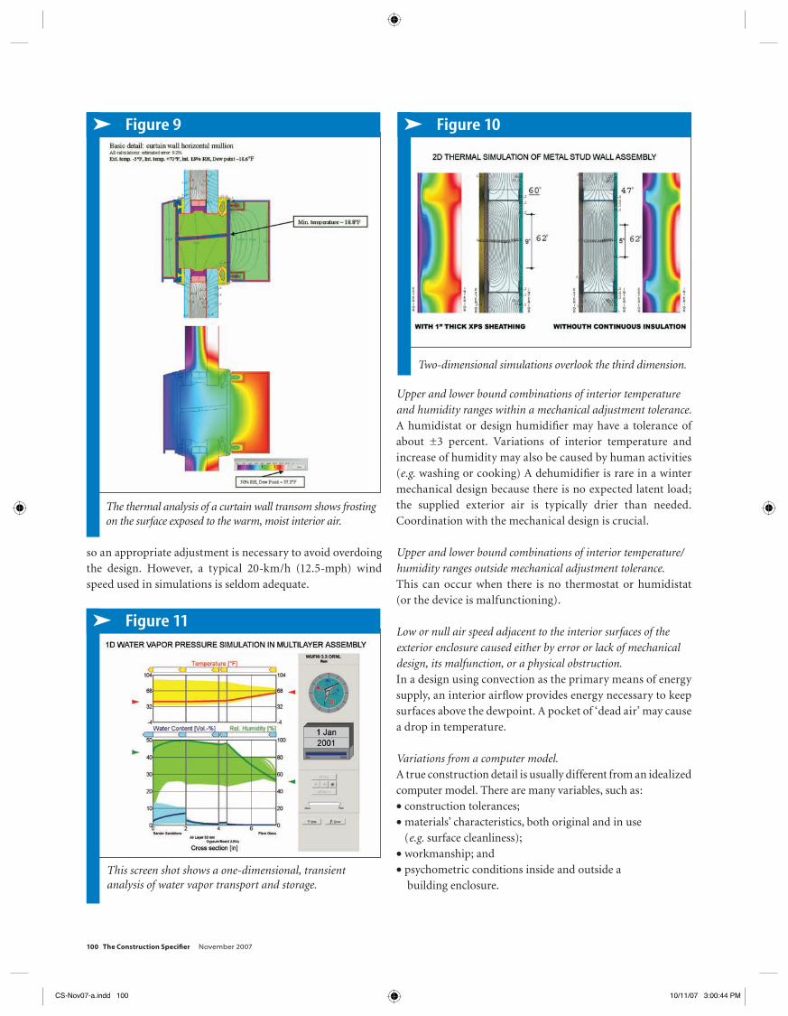
The results of a thermal simulation of a similar transom profi le in Figure 9 (page 100)—designed for a particularly cold part of Virginia—show the temperature at this surface is –7.3 C (18.8 F).
When should the assessment occur?A preliminary condensation risk review should take place as early as possible in the construction design stage. The best design is one that does not need detailed condensation risk simulations. If at a certain stage there is a suspicion condensation may become a problem, the expensive
simulations would probably describe the situation scientifi cally, but the solution would still remain the same: change the design.
The process is sometimes specifi ed in lieu of American Architectural Manufacturers Association (AAMA) 1503, Voluntary Test Method for Thermal Transmittance and Condensation Resistance of Windows, Doors, and Glazed Wall Sections, and performed during an early construction phase by a consultant hired by a glazing subcontractor. Consequently, the necessity of design modifi cation may come as a late and unpleasant surprise for both the designer-of-record and the design-build team, potentially delaying fabrication and construction, as well as generating a claim for additional time and costs.
A subcontractor may have a legitimate complaint against the design-team-of-record when no earlier assessments were performed to check the soundness of an architectural design.
➤ Figure 6
The photo above shows cold doors in insulated curtain walls, along with the resulting condensation on their interior surface.
➤ Figure 7
This thermally broken door is properly integrated with a curtain wall.
➤ Figure 8
Not all ‘thermally improved’ aluminum assemblies are designed as equals. See also Figure 9 (page 100).
Fig
ure
co
urt
esy
Edw
ard
Alle
n’s
Arc
hite
ctur
al D
etai
ling:
Func
tion,
Con
stru
ctib
ility
, Aes
thet
ics
(199
3). R
epri
nte
d
wit
h p
erm
issi
on
of J
oh
n W
iley
& S
on
s In
c.
Fig
ure
co
urt
esy
Sap
aFro
nt
Pola
nd
.
CS-Nov07-a.indd 98CS-Nov07-a.indd 98 10/11/07 3:00:31 PM10/11/07 3:00:31 PM
November 2007 The Construction Specifi er 99
Some may request an engineering change order. At this stage, it is also too late for any changes to the adjacent assemblies—they often remain unreported because they are located outside the glazing subcontractor’s scope.
This potential unpleasant situation is best averted by performing on initial condensation risk review at the early stages of the construction design stage, when the lesser dimensional relationships are defi ned on basis of conceptual details.
The consultant may fi rst give general guidance on the principles of building enclosure design, and then once the fi rst set of details is fi nished, may run inexpensive, simplifi ed thermal simulations of the most suspicious details, saving the design team from a potential embarrassment of change orders down the road. A design team that ambitiously designs custom façades on a regular basis may need to employ or train someone to perform such assessments in-house.
Limitations of typical assessmentsWhen it comes to reading assessment reports, it is important to remember “low risk of condensation” does not mean it will never form during the building’s life. The average design conditions listed in the architectural specifi cations are not
necessarily maintained in the center of their range in real life. Some conditions—alone or in combination—that can possibly lead to condensation are discussed in the following paragraphs. (To overcome some of these limitations, additional analyses may be performed for the worst-case scenarios based on the lowest construction tolerances and harshest recorded weather events.)
External temperatures falling below the design temperature.Certain locales may experience more extreme conditions than the ones statistically determined for the whole region on the basis of an average 50-year period. The building owner may have a good knowledge of local conditions if he or she lives in the area.
High winds, exceeding the design velocity, in conjunction with, at, or near design temperature.Exterior airfl ow chills the exterior surface; wind speed varies with location, exposure, and height. A good indication is the structural wind pressure map prepared in accordance with the wind tunnel tests or American Society of Civil Engineers (ASCE) 7, Minimum Design Loads for Buildings and Other Structures. The numbers represent the 50-year occurrence,
Award_2H.indd 1 10/11/07 9:09:21 AM
CS-Nov07-a.indd 99CS-Nov07-a.indd 99 10/11/07 3:00:44 PM10/11/07 3:00:44 PM
100 The Construction Specifi er November 2007
so an appropriate adjustment is necessary to avoid overdoing the design. However, a typical 20-km/h (12.5-mph) wind speed used in simulations is seldom adequate.
Upper and lower bound combinations of interior temperature and humidity ranges within a mechanical adjustment tolerance.A humidistat or design humidifi er may have a tolerance of about ±3 percent. Variations of interior temperature and increase of humidity may also be caused by human activities (e.g. washing or cooking) A dehumidifi er is rare in a winter mechanical design because there is no expected latent load; the supplied exterior air is typically drier than needed. Coordination with the mechanical design is crucial.
Upper and lower bound combinations of interior temperature/ humidity ranges outside mechanical adjustment tolerance.This can occur when there is no thermostat or humidistat (or the device is malfunctioning).
Low or null air speed adjacent to the interior surfaces of the exterior enclosure caused either by error or lack of mechanical design, its malfunction, or a physical obstruction.In a design using convection as the primary means of energy supply, an interior airfl ow provides energy necessary to keep surfaces above the dewpoint. A pocket of ‘dead air’ may cause a drop in temperature.
Variations from a computer model.A true construction detail is usually different from an idealized computer model. There are many variables, such as:• construction tolerances;• materials’ characteristics, both original and in use
(e.g. surface cleanliness);• workmanship; and• psychometric conditions inside and outside a
building enclosure.
➤ Figure 11
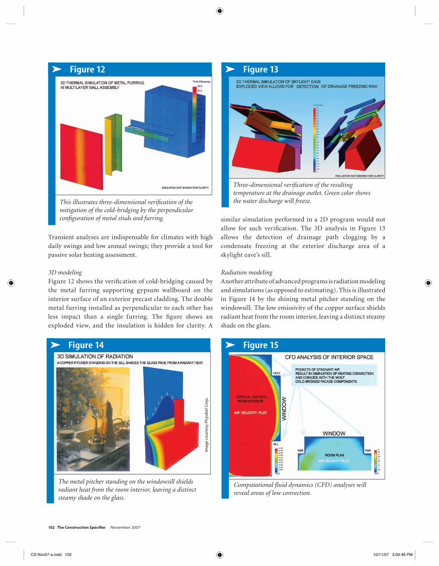
This screen shot shows a one-dimensional, transient analysis of water vapor transport and storage.
➤ Figure 9
The thermal analysis of a curtain wall transom shows frosting on the surface exposed to the warm, moist interior air.
➤ Figure 10
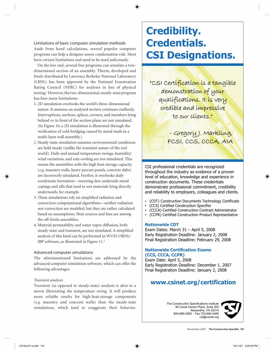
Two-dimensional simulations overlook the third dimension.
CS-Nov07-a.indd 100CS-Nov07-a.indd 100 10/11/07 3:00:44 PM10/11/07 3:00:44 PM
November 2007 The Construction Specifi er 101
Limitations of basic computer simulation methodsAside from hand calculations, several popular computer programs can help a designer assess condensation risk. Most have certain limitations and need to be used judiciously.
On the low end, several free programs can simulate a two-dimensional section of an assembly. Therm, developed and freely distributed by Lawrence Berkeley National Laboratory (LBNL) has been approved by the National Fenestration Rating Council (NFRC) for analyses in lieu of physical testing.1 However, the two-dimensional, steady-state program has four main limitations:1. 2D simulation overlooks the world’s three-dimensional
nature. It assumes an analyzed section continues endlessly. Interruptions, anchors, splices, corners, and members lying behind or in front of the section plane are not simulated. (In Figure 10, a 2D simulation is illustrated through the verifi cation of cold-bridging caused by metal studs in a multi-layer wall assembly.)
2. Steady-state simulation assumes environmental conditions are held steady (unlike the transient nature of the real world). Daily and annual temperature swings, humidity/wind variations, and rain cooling are not simulated. This means the assemblies with the high heat storage capacity (e.g. masonry walls, heavy precast panels, concrete slabs) are incorrectly simulated. Further, it overlooks daily condensate formation—morning dew underside metal copings and sills that tend to wet materials lying directly underneath, for example.
3. These simulations rely on simplifi ed radiation and convection computational algorithms—neither radiation nor convection are modeled, but they are rather calculated based on assumptions. Heat sources and fans are among the off-limits assemblies.
4. Material permeability and water vapor diffusion, both steady-state and transient, are not simulated. A simplifi ed analysis of this kind can be performed in WUFI-ORNL/IBP software, as illustrated in Figure 11.2
Advanced computer simulationsThe aforementioned limitations are addressed by the advanced computer simulation software, which can offer the following advantages.
Transient analysisTransient (as opposed to steady-state) analysis is akin to a movie illustrating the temperature swing. It will produce more reliable results for high-heat-storage components (e.g. masonry and concrete walls) than the steady-state simulations, which tend to exaggerate their behavior.
The Construction Specifications Institute 99 Canal Center Plaza, Suite 300
Alexandria, VA 22314 800-689-2900 Fax 703-684-0465
CSI professional credentials are recognized throughout the industry as evidence of a proven level of education, knowledge and experience in construction documents. These credentials demonstrate professional commitment, credibility and reliability to employers, colleagues and clients.
(CDT) Construction Documents Technology Certificate(CCS) Certified Construction Specifier (CCCA) Certified Construction Contract Administrator (CCPR) Certified Construction Product Representative
Nationwide CDT Exam Dates: March 31 – April 5, 2008 Early Registration Deadline: January 2, 2008 Final Registration Deadline: February 29, 2008
Nationwide Certification Exams (CCS, CCCA, CCPR) Exam Date: April 5, 2008 Early Registration Deadline: December 1, 2007 Final Registration Deadline: January 2, 2008
www.csinet.org/certification
Credibility.Credentials.CSI Designations.
"CSI Certification is a tangibledemonstration of yourqualifications. It is verycredible and impressiveto our clients."
- Gregory J. Markling,FCSI, CCS, CCCA, AIA
Cert_2V.indd 1 10/11/07 9:23:57 AM
CS-Nov07-a.indd 101CS-Nov07-a.indd 101 10/11/07 3:00:46 PM10/11/07 3:00:46 PM
102 The Construction Specifi er November 2007
Transient analyses are indispensable for climates with high daily swings and low annual swings; they provide a tool for passive solar heating assessment.
3D modelingFigure 12 shows the verifi cation of cold-bridging caused by the metal furring supporting gypsum wallboard on the interior surface of an exterior precast cladding. The double metal furring installed as perpendicular to each other has less impact than a single furring. The fi gure shows an exploded view, and the insulation is hidden for clarity. A
similar simulation performed in a 2D program would not allow for such verifi cation. The 3D analysis in Figure 13 allows the detection of drainage path clogging by a condensate freezing at the exterior discharge area of a skylight eave’s sill.
Radiation modelingAnother attribute of advanced programs is radiation modeling and simulations (as opposed to estimating). This is illustrated in Figure 14 by the shining metal pitcher standing on the windowsill. The low emissivity of the copper surface shields radiant heat from the room interior, leaving a distinct steamy shade on the glass.
➤ Figure 13
Three-dimensional verifi cation of the resulting temperature at the drainage outlet. Green color shows the water discharge will freeze.
➤ Figure 14
The metal pitcher standing on the windowsill shields radiant heat from the room interior, leaving a distinct steamy shade on the glass.
Imag
e co
urt
esy
Phys
ibel
Co
rp.
➤ Figure 15
Computational fl uid dynamics (CFD) analyses will reveal areas of low convection.
➤ Figure 12
This illustrates three-dimensional verifi cation of the mitigation of the cold-bridging by the perpendicular confi guration of metal studs and furring.
CS-Nov07-a.indd 102CS-Nov07-a.indd 102 10/11/07 3:00:46 PM10/11/07 3:00:46 PM

November 2007 The Construction Specifi er 103
Computational fl uid dynamicsComputational fl uid dynamics (CFD) convection simulations (as opposed to estimating) are another component of advanced programs. Figure 15 illustrates the drop of convection heating at window and ceiling perimeters, which forms pockets of stagnant air; coincidently, these areas are most prone to cold-bridging.
Water vapor diffusion analyses are needed in assemblies not containing at least one impermeable screen at any analyzed wall fragment. While it is available, most glazing analyses do not need detailed CFD hygrothermal analysis because the materials involved (e.g. glass and metals) are impermeable, and the analysis cannot fully estimate discrepancies between the design and as-build condition, which strongly infl uence water vapor diffusion.
Selecting the proper softwareThe long learning curve and the high cost of these advanced programs usually prove prohibitive for an average architect. Further, the required customization, mechanical knowledge, limited data exchange, and model size make them exclusive tools. The engineering costs that may be justifi ed by the
returns expected on mass-produced items do not apply in the construction industry where projects are individually designed and built. “What Do You Need?” (page 104) provides a simplifi ed decision-making diagram for determining which computer simulations are necessary for a particular project.
The 2006 International Building Code (IBC) contains two provisions for condensation prevention. Both Section 1301 of Chapter 13 (Energy Effi ciency) and Section 1403 of Chapter 14 (Exterior Walls) refer to the International Energy Conservation Code (IECC), which in turn contains separate requirements for residential and commercial buildings: 502.1.1 and 802.1.2, respectively. IECC also provides the American Society of Heating, Refrigerating, and Air-conditioning Engineers (ASHRAE) 90.1-2004, Energy Standard for Buildings Except Low-rise Residential Buildings, as an alternative path of compliance for commercial buildings.
Codes and Legislation
Are You Prepared to Manage the Complexities of a LEED Project?
Earn your CDT Certificate or advanced CSI Certification and get your construction
documentation in order.
Construction Documents Technology (CDT) CertificateCertified Construction Specifier (CCS)Certified Construction Contract Administrator (CCCA)Certified Construction Product Representative (CCPR)
www.csinet.org/certification
The Construction Specifications Institute 99 Canal Center Plaza, Suite 300
Alexandria, VA 22314 800-689-2900 Fax 703-684-0465
Cert_2H.indd 1 10/11/07 9:21:35 AM
CS-Nov07-a.indd 103CS-Nov07-a.indd 103 10/11/07 3:00:48 PM10/11/07 3:00:48 PM
104 The Construction Specifi er November 2007
Specifying against condensationA quick scan of typical warranties shows many curtain wall manufacturers specifi cally and expressly exclude the responsibility for frost and condensation. Consequently, it is up to the designer to specify a proper glazing assembly.
It is crucial to verify the requirements are achievable. Manufacturers of most off-the-shelf products have them already tested. The designer-of-record should request and review AAMA 1503 test reports before the product is chosen. He or she should only accept the reports when the following requirements are jointly met:• exterior design temperature is equal to or higher than the
one specifi ed in the testing standard (–17.8 C [0 F]);• interior design temperature is equal to or greater than the
one specifi ed in the test (21 C [69.8 F]);
• design wind speed is equal/lower than 6.7 m/s (15 mph); and• temperatures read by all the thermocouples located on the
frame are equal to or above the design dewpoint.The typical interior design temperature is in the range of 22.2 to 23.9 C (72 to 75 F). A higher interior ambient temperature produces a higher dewpoint temperature. It also slightly warms the interior surface, but in a much less proportional and predictable way. A better glass should be specified if the designed glass has a lower U-value than the one used at the test, or the temperature read by any thermocouple located on the glass is below the design dewpoint.
In case the design confi guration varies from the one already tested (e.g. a curtain wall contains an untested door), or any signifi cant modifi cations are made to the
This fl owchart can help when it comes time to determine which simulations are necessary for a project.
What Do You Need?
CS-Nov07-a.indd 104CS-Nov07-a.indd 104 10/11/07 3:00:49 PM10/11/07 3:00:49 PM
November 2007 The Construction Specifi er 105
tested product (e.g. extended decorative exterior trim), a thermal simulation or test is needed to re-verify the design. A thermal computer simulation is typically less expensive than a laboratory test.
Either thermal tests or simulations should be specifi ed if the product was not tested before (e.g. custom or modifi ed glazing assemblies) or the design temperatures unfavorably differ from the ones specifi ed in AAMA 1503.
A properly performed condensation risk assessment of the glazing should model all adjacent conditions based on shop drawings and actual materials, rather than the architectural drawings. Specifi cations of adjacent mechanical equipment should be referenced in order to allow proper bid documentation packaging.
The designer-of-record should always request the detailed explanations of assumptions, copies of drawings used for modeling, list of physical characteristics of
• Joseph Lstiburek and John Carmody’s Moisture Control Handbook: Principles and Practices for Residential and Small Commercial Buildings (John Wiley & Sons, 1994); and
• ASHRAE Handbook of Fundamentals (American Society of Heating, Refrigerating, and Air-Conditioning Engineers, 2005).
Examples of sound façade details can be found in:• Friedbert Kind-Barkauskas et al’s Concrete Construc-
tion Manual (Birkhauser, 2002);• Gunter Pfeifer et al’s Masonry Construction Manual
(Birkhauser, 2001);• Thomas Herzog’s Façade Construction Manual
(Birkhauser, 2004);• Christian Schittich et al’s Glass Construction Manual
(Birkhauser, 1999);• Christian Schittich’s In Detail: Building Skins—
Concepts, Layers, Materials (Birkhauser, 2001); and• the monthly English edition of magazine titled
Detail (Institut fuer Internationale Architecktur-Dokumentation GmbH&Co).
Of course, additional worthwhile reading materials are available free of charge via the Internet. Visit the Web page of Canada’s University of Waterloo (www.civil.uwaterloo.ca/beg/Publications.htm), along with John Straube’s www.balancedsolutions.com. Another rich library of free scientifi c articles is also available at the Web page of the National Research Council of Canada’s Institute of Research in Construction at irc.nrc-cnrc.gc.ca.
Recommended Reading
Train your entire team with only one registration fee!
CSI Webinars are 90-minute interactive telephone/Internet education programs offered 2 – 3:30 pm ET.Each session provides convenient, quality learning at an affordable price – you’ll be able to see materials, hear an instructor and ask questions in real time. Par-ticipants are charged by site, which means you can invite as many colleagues as you wish to attend the session at your location and share the cost!
The cost per webinar site is ONLY $75 for CSI members, or $95 for non-members.
CSI Webinars
The Construction Specifications Institute 99 Canal Center Plaza, Suite 300 Alexandria, VA 22314 800-689-2900 Fax 703-684-0465 [email protected]
November 6 Submittals & Substitutions
November 13 MasterFormat for Engineers – HVAC
November 14 CSI Certification: Computer Based Testing and
National Exam Information for CSI Leaders
November 20 The LEED Family of Rating Systems: Understanding the Differences & Similarities
November 27 How to put a Project Manual Together - Making it all Work
December 4 Evaluating and Specifying Sustainable Product Attributes
December 11 To Be or Not to Be Vapor Permeable! Selecting the Proper Envelope Barriers Based on Climate, Codes & Design Criteria
December 18 How the Courts Interpret Specifications
Upcoming Sessions:
Most courses qualify for 0.15 CSI Continuing Education Units (CEUs) and 1.5 AIA Learning Units (LUs).
For a complete program listing, or to register visit www.csinet.org/webinar
Get the Education You Need Anywhere You Want!
Webinar_2V.indd 1 10/11/07 9:29:12 AM
CS-Nov07-a.indd 105CS-Nov07-a.indd 105 10/11/07 3:00:53 PM10/11/07 3:00:53 PM
106 The Construction Specifi er November 2007
materials used for modeling, and boundary conditions. The materials’ assignment should be declared on graphics, and the definition of unacceptable condensation must be clarified.
The architect should demand the psychrometric design conditions (i.e. temperatures, air speeds, and humidities) from
the mechanical engineer and provide them in the specifi cation for the glazing subcontractor design-build team.
On the other hand, for installations of fenestration in typical mechanical and weather conditions when the detailed tests or simulations are not specifi ed, the condensation resistance factor (CRF) should be made clear.
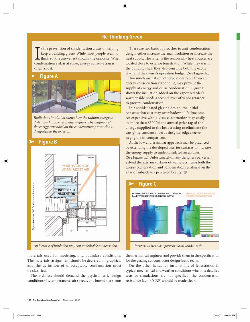
➤ Figure A
Radiation simulation shows how the radiant energy is distributed on the receiving surfaces. The majority of the energy expended on the condensation prevention is dissipated to the exterior.
Imag
e co
urt
esy
Phys
ibel
Co
rp.
Is the prevention of condensation a way of helping keep a building green? While most people seem to think so, the answer is typically the opposite. When
condensation risk is at stake, energy conservation is often a cost.
There are two basic approaches to anti-condensation design: either increase thermal insulation or increase the heat supply. The latter is the reason why heat sources are located close to exterior fenestration. While they warm the building shell, they also consume both the ozone layer and the owner’s operation budget (See Figure A.)
Too much insulation, otherwise desirable from an energy conservation standpoint, may prevent the supply of energy and cause condensation. Figure B shows the insulation added on the vapor retarder’s warmer side needs a second layer of vapor retarder to prevent condensation.
In a sophisticated glazing design, the initial construction cost may overshadow a lifetime cost. An expensive whole-glass construction may easily be more than $500/sf; the annual price tag of the energy supplied to the heat tracing to eliminate the unsightly condensation at the glass edges seems negligible in comparison.
At the low end, a similar approach may be practiced by extending the developed interior surfaces to increase the energy supply to under-insulated assemblies. (See Figure C.) Unfortunately, many designers perversely extend the exterior surfaces of walls, sacrifi cing both the energy conservation and condensation resistance on the altar of subjectively perceived beauty.
Re-thinking Green
➤ Figure B
An increase of insulation may cost undesirable condensation.
➤ Figure C
Increase in heat loss prevents local condensation.
Fig
ure
co
urt
esy
FWB
Bro
ekel
man
n A
lum
inu
m
CS-Nov07-a.indd 106CS-Nov07-a.indd 106 10/11/07 3:00:54 PM10/11/07 3:00:54 PM
November 2007 The Construction Specifi er 107
Understanding condensation resistance factorCondensation resistance factor is a dimensionless number indirectly representing a weighted average interior surface temperature of a window assembly. The larger the CRF number, the greater the resistance to condensation. It helps to remember the average interior surface temperature expressed in degrees of Fahrenheit could be approximately derived from CRF by multiplying the condensation resistance factor by 0.7. For example, CRF 50 translates into approximately 35 F (1.67 C.)
It often conveys a disturbing message that some thermocouples might read an even lower temperature during the test, but to fi nd out, one has to request and read a detailed test report. (These documents need to be ordered in advance because they are not typically supplied by default.)
Intended for comparison of the typical off-the-shelf fenestration assemblies, CRF nevertheless heavily relies on the glass quality and is almost useless in a detailed condensation assessment for custom fenestration or a custom psychometric set of parameters (e.g. different exterior design temperature).
CRF is determined by the testing specifi ed in the AAMA 1503. Another similar measure is the Temperature Index I defi ned by Canadian Standards Association (CSA) A 440-90, Windows, and A 440.1-91. Further, NFRC has come up with a similar standard NFRC 500, Procedure for Determining
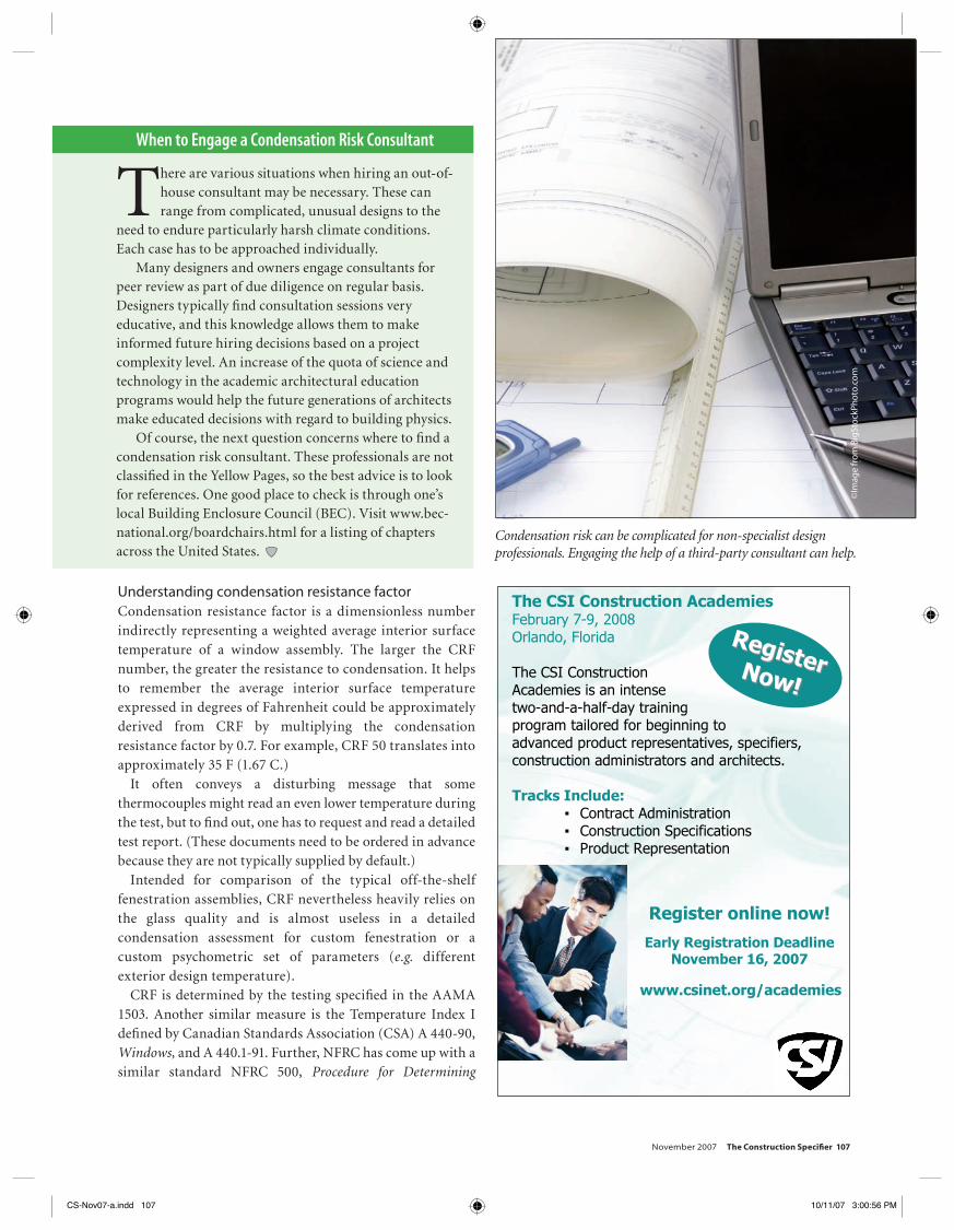
Condensation risk can be complicated for non-specialist design professionals. Engaging the help of a third-party consultant can help.
There are various situations when hiring an out-of-house consultant may be necessary. These can range from complicated, unusual designs to the
need to endure particularly harsh climate conditions. Each case has to be approached individually.
Many designers and owners engage consultants for peer review as part of due diligence on regular basis. Designers typically fi nd consultation sessions very educative, and this knowledge allows them to make informed future hiring decisions based on a project complexity level. An increase of the quota of science and technology in the academic architectural education programs would help the future generations of architects make educated decisions with regard to building physics.
Of course, the next question concerns where to fi nd a condensation risk consultant. These professionals are not classifi ed in the Yellow Pages, so the best advice is to look for references. One good place to check is through one’s local Building Enclosure Council (BEC). Visit www.bec-national.org/boardchairs.html for a listing of chapters across the United States.
When to Engage a Condensation Risk Consultant
©Im
age
fro
m B
igSt
ock
Pho
to.c
om
The CSI Construction Academies February 7-9, 2008 Orlando, Florida
The CSI Construction Academies is an intense two-and-a-half-day training program tailored for beginning to advanced product representatives, specifiers, construction administrators and architects.
Tracks Include: Contract Administration Construction Specifications Product Representation
Register online now!
Early Registration Deadline November 16, 2007
RegisterRegisterNow!Now!
www.csinet.org/academies
Academies_4V.indd 1 10/11/07 9:07:27 AM
CS-Nov07-a.indd 107CS-Nov07-a.indd 107 10/11/07 3:00:56 PM10/11/07 3:00:56 PM
108 The Construction Specifi er November 2007
Fenestration. Most differences lie in the method applied to weighting the average temperature.
Manufacturers feel compelled to list two types of CRF: one for glass (CRF
g), and one for the frame (CRF
f).
Apparently, the latter better describes assembly quality and helps with the comparison among fenestration products. Comparing CRF
g, a designer should verify whether the
specifi ed glass and spacer are equal or better than the ones originall tested..
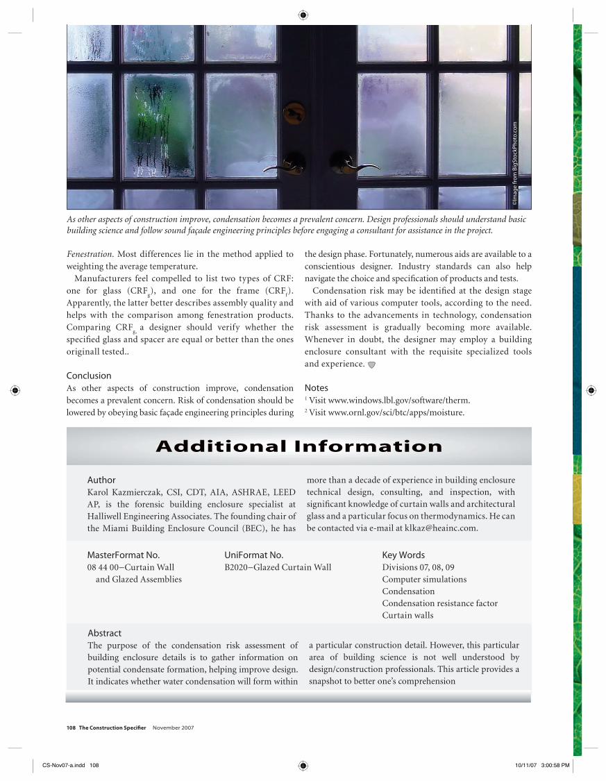
ConclusionAs other aspects of construction improve, condensation becomes a prevalent concern. Risk of condensation should be lowered by obeying basic façade engineering principles during
the design phase. Fortunately, numerous aids are available to a conscientious designer. Industry standards can also help navigate the choice and specifi cation of products and tests.
Condensation risk may be identifi ed at the design stage with aid of various computer tools, according to the need. Thanks to the advancements in technology, condensation risk assessment is gradually becoming more available. Whenever in doubt, the designer may employ a building enclosure consultant with the requisite specialized tools and experience.
Notes1 Visit www.windows.lbl.gov/software/therm.2 Visit www.ornl.gov/sci/btc/apps/moisture.
Additional Information
AuthorKarol Kazmierczak, CSI, CDT, AIA, ASHRAE, LEED AP, is the forensic building enclosure specialist at Halliwell Engineering Associates. The founding chair of the Miami Building Enclosure Council (BEC), he has
more than a decade of experience in building enclosure technical design, consulting, and inspection, with signifi cant knowledge of curtain walls and architectural glass and a particular focus on thermodynamics. He can be contacted via e-mail at [email protected].
AbstractThe purpose of the condensation risk assessment of building enclosure details is to gather information on potential condensate formation, helping improve design. It indicates whether water condensation will form within
a particular construction detail. However, this particular area of building science is not well understood by design/construction professionals. This article provides a snapshot to better one’s comprehension
MasterFormat No.08 44 00−Curtain Wall and Glazed Assemblies
UniFormat No.B2020−Glazed Curtain Wall
Key WordsDivisions 07, 08, 09Computer simulationsCondensationCondensation resistance factorCurtain walls
As other aspects of construction improve, condensation becomes a prevalent concern. Design professionals should understand basic building science and follow sound façade engineering principles before engaging a consultant for assistance in the project.
©Im
age
fro
m B
igSt
ock
Pho
to.c
om
GreenEnvy_Ad.indd 1 10/11/07 9:26:39 AMCS-Nov07-a.indd 108CS-Nov07-a.indd 108 10/11/07 3:00:58 PM10/11/07 3:00:58 PM
![Constructibility and duality for simple holonomic modules ... · PDF filearXiv:math/0512047v2 [math.QA] 10 Jun 2007 Constructibility and duality for simple holonomic modules on complex](https://img.pdfslide.net/doc/110x75/5a7daebc7f8b9a72118dc316/constructibility-and-duality-for-simple-holonomic-modules-math0512047v2-mathqa.jpg)