Embed Size (px)
Citation preview

Waters In-Line Degasser AFOperator’s Guide
34 Maple StreetMilford, MA 01757
71500030802, Revision A

NOTICE
The information in this document is subject to change without notice and should not be construed as a commitment by Waters Corporation. Waters Corporation assumes no responsibility for any errors that may appear in this document. This manual is believed to be complete and accurate at the time of publication. In no event shall Waters Corporation be liable for incidental or consequential damages in connection with or arising from the use of this manual.
2001 WATERS CORPORATION. PRINTED IN THE UNITED STATES OF AMERICA. ALL RIGHTS RESERVED. THIS BOOK OR PARTS THEREOF MAY NOT BE REPRODUCED IN ANY FORM WITHOUT THE WRITTEN PERMISSION OF THE PUBLISHER.
Waters is a registered trademark of Waters Corporation.
Kalrez, Teflon, and Tefzel are registered trademarks of E. I. du Pont de Nemours and Company.
Milli-Q is a trademark of Millipore Corporation.
TORX is a trademark of Camcar, Division of Textron, Inc.
Tygon is a registered trademark of Norton Company.
All other trademarks or registered trademarks are the sole property of their respective owners.

The Installation Category (Overvoltage Category) for this instrument is Level II. The Level II category pertains to equipment that receives its electrical power from a local level, such as an electrical wall outlet.
STOPAttention: To meet the regulatory requirements of immunity from external electrical disturbances that may affect the performance of this instrument, do not use cables longer than 9.8 feet (3 meters) when you make connections to the screw-type barrier terminal strips. In addition, ensure you always connect the shield of the cable to chassis ground at one instrument only.
STOPAttention: Changes or modifications to this unit not expressly approved by the party responsible for compliance could void the user’s authority to operate the equipment.
Caution: To protect against fire hazard, replace fuses with those of the same type and rating.
Caution: If the equipment is used in a manner not specified in this document, the protection provided by the equipment may be impaired.
Caution: Use caution when working with any organic polymer tubing under pressure.
• Always wear eye protection when near pressurized polymer tubing.
• Extinguish all nearby flames.
• Do not use Tefzel tubing that has been kinked or severely stressed.
Caution: To avoid possible electric shock, do not open the power supply cover. The power supply does not contain user-serviceable components.
Symbols Used on the In-Line Degasser AF
Direct current
Alternating current
Protective conductor terminal
Frame or chassis terminal
Caution, risk of electric shock (high voltage)
Caution or refer to manual
Caution, hot surface or high temperature

In-Line Degasser AF Information
Intended Use
The Waters® In-Line Degasser AF can be used for in-vitro diagnostic testing to analyze many compounds, including diagnostic indicators and therapeutically monitored compounds. When you develop methods, follow the “Protocol for the Adoption of Analytical Methods in the Clinical Chemistry Laboratory,” American Journal of Medical Technology, 44, 1, pages 30–37 (1978). This protocol covers good operating procedures and techniques necessary to validate system and method performance.
Biological Hazard
When you analyze physiological fluids, take all necessary precautions and treat all specimens as potentially infectious. Precautions are outlined in “CDC Guidelines on Specimen Handling,” CDC – NIH Manual, 1984.
Calibration
Follow acceptable methods of calibration with pure standards to calibrate methods. Use a minimum of five standards to generate a standard curve. The concentration range should cover the entire range of quality-control samples, typical specimens, and atypical specimens.
Quality Control
Routinely run three quality-control samples. Quality-control samples should represent subnormal, normal, and above-normal levels of a compound. Ensure that quality-control sample results are within an acceptable range, and evaluate precision from day to day and run to run. Data collected when quality-control samples are out of range may not be valid. Do not report this data until you ensure that chromatographic system performance is acceptable.

Table of Contents
Preface ............................................................................................ 12
Chapter 1 Introduction ...................................................................................... 16
1.1 About the In-Line Degasser AF............................................. 16
1.2 Theory of Operation .............................................................. 20
1.2.1 Operating Principles .................................................. 20
1.2.2 Effects of Dissolved Oxygen ...................................... 21
1.2.3 Degassing Methods ................................................... 22
1.3 Installation Site Requirements .............................................. 23
1.4 Unpacking and Inspection..................................................... 24
1.5 Safety Summary ................................................................... 25
Chapter 2 Making Electrical Connections ........................................................ 26
2.1 Voltage Selection and Fuse Installation ................................ 26
2.2 Connecting to Other Instruments .......................................... 29
2.2.1 Connecting the External Control Terminals ............... 30
2.2.2 Vacuum Terminals ..................................................... 32
Chapter 3 Making Fluidic Connections ............................................................. 35
3.1 Installing with Waters 600 Series Pumps.............................. 37
3.2 Installing with Waters 510/515 or 1515/1525 HPLC Pumps....................................................................... 40
Table of Contents 6

3.3 Installing with Non-Waters Pumps ........................................ 43
3.4 Installing the Vent Line .......................................................... 44
Chapter 4 Using the In-Line Degasser AF ....................................................... 46
4.1 Powering Up.......................................................................... 46
4.2 In-Line Degasser AF Operation ............................................ 47
4.2.1 Operating Statuses .................................................... 47
4.2.2 Degassing Efficiency ................................................. 48
4.3 Controlling the Degasser Externally...................................... 50
4.4 Powering Down ..................................................................... 51
Chapter 5 Troubleshooting and Service ........................................................... 52
5.1 Troubleshooting..................................................................... 52
5.2 Service .................................................................................. 57
5.2.1 Removing and Installing the Cover ............................ 57
5.2.2 Disconnecting Eluent Lines ....................................... 58
5.2.3 Purging the Eluent Tubing in Vacuum Chambers ...... 58
5.2.4 Draining the Vacuum Tubing and Chambers ............. 59
5.2.5 Testing the Vacuum Sensor ....................................... 61
5.2.6 Testing the Power Supply........................................... 62
5.2.7 Testing the Control Board Assembly.......................... 65
5.2.8 Testing the Vacuum Pump ......................................... 66
5.2.9 Testing the Vacuum Chambers .................................. 68
5.2.10 Replacing a Vacuum Chamber ................................ 70
Table of Contents 7

Appendix A Specifications ................................................................................... 73
Appendix B Spare Parts....................................................................................... 75
Index ............................................................................................ 77
Table of Contents 8

List of Figures
1-1 Waters In-Line Degasser AF, Two-Channel ................................... 161-2 Major Systems in the In-Line Degasser AF ................................... 181-3 Vacuum Chamber Schematic ........................................................ 20
2-1 Fuse Holder on Rear Panel ........................................................... 282-2 Rear Panel Connector ................................................................... 292-3 Waters 600 Series Controller Connection ..................................... 322-4 Comparison of Vacuum Terminal Signal Output ............................ 33
3-1 Ferrule and Compression Screw Assembly................................... 363-2 Positioning the In-Line Degasser AF in a Waters HPLC System... 373-3 Connecting an Inlet Line to the In-Line Degasser AF .................... 383-4 Connecting an Outlet Line to the In-Line Degasser AF ................. 393-5 Positioning the In-Line Degasser AF with the Waters 510 or
515 Pump (515 Shown) ................................................................. 403-6 Positioning the In-Line Degasser AF with the Waters 1515 or
1525 Pump .................................................................................... 413-7 Connecting an Inlet Line to the In-Line Degasser AF .................... 423-8 Connecting an Outlet Line to the In-Line Degasser AF ................. 433-9 Vent Fitting on Rear Panel ............................................................. 44
4-1 Two Vacuum Chambers in Series .................................................. 49
5-1 Vacuum Troubleshooting Tree........................................................ 545-2 Electrical Troubleshooting Tree ...................................................... 565-3 Testing the Vacuum Sensor ........................................................... 615-4 Power Connector Receptacle on Control Board Assembly............ 635-5 Vacuum Connections to Test the Vacuum Pump ........................... 675-6 Vacuum Connections to Test a Vacuum Chamber......................... 69
Table of Contents 9
5-7 Vacuum Tubing Schematic for a Degasser with Two Vacuum Chambers ...................................................................................... 71
5-8 Vacuum Tubing Schematic for a Degasser with Three Vacuum Chambers ...................................................................................... 71
5-9 Vacuum Tubing Schematic for a Degasser with Four Vacuum Chambers ...................................................................................... 72
Table of Contents 10

Table of Contents 11
1-1 Installation Site Requirements ...................................................... 23
2-1 Voltage and Fuse Selection .......................................................... 272-2 Rear Panel Terminals .............................................................. 30
4-1 Effect of Flow Rate on Final Dissolved Gas Concentration .......... 48
5-1 LED Indications ............................................................................. 535-2 Tubing Schematics .................................................................. 70
A-1 Operational Specifications ............................................................ 73
B-1 Spare Parts ................................................................................... 75
List of Tables

PrefaceThe Waters In-Line Degasser AF Operator’s Guide describes the procedures for unpacking, installing, operating, maintaining, troubleshooting, and servicing the Waters® In-Line Degasser AF. It also includes appendixes describing the specifications and spare parts for the degasser.
This guide is intended for use by personnel who need to install, operate, maintain, troubleshoot, and service the Waters In-Line Degasser AF.
Organization
This guide contains the following:
Chapter 1, Introduction, describes the degasser, including the theory of operation, and provides a safety summary, installation site requirements, and directions for unpacking the degasser.
Chapter 2, Making Electrical Connections, describes the procedures for making electrical connections.
Chapter 3, Making Fluidic Connections, provides procedures for installing the In-Line Degasser AF with Waters pumps and HPLC systems with non-Waters pumps.
Chapter 4, Using the In-Line Degasser AF, explains how to use the In-Line Degasser AF.
Chapter 5, Troubleshooting and Service, describes troubleshooting and service procedures for the In-Line Degasser AF.
Appendix A, Specifications, lists the specifications of the In-Line Degasser AF.
Appendix B, Spare Parts, provides a list of recommended and optional spare parts.
Related Documentation
Waters 600E Multisolvent Delivery System User’s Guide: Provides instructions for using the 600 Series Controller, which can be used to control the In-Line Degasser AF.
Waters Licenses, Warranties, and Support: Provides software license and warranty information, describes training and extended support, and tells how Waters handles shipments, damages, claims, and returns.
How To Use This Guide 12

Documentation Conventions
The following conventions may be used in this guide:
Related Adobe™ Acrobat Reader Documentation
For detailed information about using the Adobe Acrobat Reader, refer to the Adobe Acrobat Reader Online Guide. This Online Guide covers procedures such as viewing, navigating and printing electronic documentation from Adobe Acrobat Reader.
Convention Usage
Bold Bold indicates user action such as keys to press, menu selections, and commands. For example, “Click Next to go to the next page.”
Italic Italic indicates information that you supply such as variables. It also indicates emphasis and document titles. For example, “Replace file_name with the actual name of your file.”
Courier Courier indicates examples of source code and system output. For example, “The SVRMGR> prompt appears.”
Courier Bold
Courier bold indicates characters that you type or keys you press in examples of source code. For example, “At the LSNRCTL> prompt, enter set password oracle to access Oracle.”
Keys The word key refers to a computer key on the keypad or keyboard. Screen keys refer to the keys on the instrument located immediately below the screen. For example, “The A/B screen key on the 2414 Detector displays the select channel.”
… Three periods (…) indicate that more of the same type of item can optionally follow. For example, “You can store filename1, filename2, ... in each folder.”
> A right arrow between menu options indicates you should select each option in sequence. For example, “Select File > Exit” means you should select File from the menu bar, then select Exit from the File menu.
How To Use This Guide 13

Printing From This Electronic Document
Adobe Acrobat Reader lets you easily print pages, pages ranges, or the entire electronic document by selecting Print from the File menu. For optimum print quantity, Waters recommends that you specify a Postscript printer driver for your printer. Ideally, use a printer that supports 600 dpi print resolution.
Conventions Used in This Guide
This guide uses the following conventions to make text easier to understand.
• Purple Text indicates user action. For example:
Press 0, then press Enter for the remaining fields.
• Italic text denotes new or important words, and is also used for emphasis. For example:
An instrument method tells the software how to acquire data.
• Underlined, Blue Color text indicates hypertext cross-references to a specific chapter, section, subsection, or sidehead. Clicking this topic using the hand symbol automatically brings you to this topic within the electronic document. Right-clicking and selecting Go Back from the popup context menu brings you back to the originating topic. For example:
Section 4.2.2, Degassing Efficiency, discusses the effect of different flow rates on the concentration of remaining gas.
Notes, Attentions, and Cautions
• Notes call out information that is helpful to the operator. For example:
Note: Record your result before you proceed to the next step.• Attentions provide information about preventing possible damage to the system or
equipment. For example:
• Cautions provide information essential to the safety of the operator. For example:
STOPAttention: To avoid damaging the equipment, do not touch the flow cell window.
Caution: To avoid possible burns, turn off the lamp at least 30 minutes before removing it for replacement or adjustment.
How To Use This Guide 14

Caution: To avoid possible electrical shock and injury, always turn off the instrument and unplug the power cord before performing maintenance procedures.
Caution: To avoid chemical or electrical hazards, always observe safe laboratory practices when operating the system.
How To Use This Guide 15

1
Chapter 1IntroductionThis chapter introduces the Waters® In-Line Degasser AF. The following topics are covered:
• Description of the In-Line Degasser AF
• Theory of vacuum degassing
• Installation site requirements
• Unpacking instructions
• Safety considerations
1.1 About the In-Line Degasser AF
The Waters In-Line Degasser AF (Figure 1-1) provides HPLC systems with an automatic, continuous method of removing dissolved gases from mobile phases.
Figure 1-1 Waters In-Line Degasser AF, Two-Channel
The standard configurations of the Waters In-Line Degasser AF provide either two or four independent fluid channels in separate vacuum chambers. Each vacuum chamber is fitted with fluid and vacuum connections.
ELUENTIN
ELUENTOUT
About the In-Line Degasser AF 16

1
Adding More Vacuum Chambers
You can add one or two additional vacuum chambers to a two-channel In-Line Degasser AF for a total of three or four channels. Appendix B, Spare Parts, contains the part number for the vacuum chamber and manifold. You can install additional vacuum chambers in your laboratory using common hand tools.
Benefits of Degassing
Removing dissolved gases from the mobile phase improves the performance and reliability of the pump and the detector. Dissolved gases in an eluent can result in:
• Outgassing in a piston chamber, causing pressure fluctuations, flow rate inconsistency, and noise in the detector baseline.
• Vapor-locked check valve which stops eluent flow from that pump head.
• Outgassing downstream of the column. Outgassing can create bubbles that pass into the detector cell, causing baseline disruptions such as spikes.
Optimal operation of the pump and detector provides the following benefits:
• Stable baselines with reduced drift and pressure fluctuations
• Reduced detector baseline noise for improved signal-to-noise ratio and more reliable quantitation
17 Introduction

1
Major Systems
Figure 1-2 shows the three major systems within the degasser:
• Eluent system
• Vacuum system
• Electrical and control system
Figure 1-2 Major Systems in the In-Line Degasser AF
Eluent System
The In-Line Degasser AF removes dissolved gases from the eluent as it passes through a tubular membrane. The membrane, enclosed in a vacuum chamber, is in the eluent flow path between the reservoir and the pump inlet.
The eluent enters and exits through inlet and outlet fittings on the vacuum chamber. These fittings are labeled on and accessible from the front panel of the In-Line Degasser AF.
Each tubular membrane is made of a proprietary, specially engineered, fluorocarbon polymer. The membrane is designed for:
• Minimum internal volume – For rapid solvent changeover.
• Minimum resistance to flow, or pressure drop – For ease in priming and accommodation of high flow rates.
Vacuum Chambers (4)
Vacuum System
System
Electrical and Control SystemVacuum Lines
Electrical Lines
Eluent Lines
Inlet
Outlet
Key:
RearVacuum
ControlBoard
PumpPanel
PanelFront
PowerSupply
Eluent
About the In-Line Degasser AF 18
1
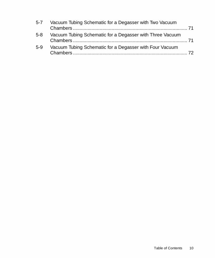
• Maximum external surface area exposed to the vacuum – For greatest gas removal efficiency.
• Maximum gas permeability – For greatest gas removal efficiency.
• Optimum chemical resistance – For compatibility with a wide spectrum of liquids, including all the mobile phases commonly encountered in HPLC.
The vacuum in the chamber accelerates the rate at which the dissolved gas diffuses through the polymer membrane into the vacuum chamber. Section 1.2, Theory of Operation, describes the principles of vacuum degassing. The gases are exhausted through a vent on the rear panel.
As with all degassing methods, some solvent vapor is also removed and vented along with the gas. Section 1.5, Safety Summary, describes the precautions necessary to minimize exposure to solvent vapors.
Vacuum System
The vacuum system provides vacuum at a preset level to the connected vacuum chambers. The vacuum system consists of the following elements:
• Vacuum pump – An electrical two-speed stepper motor pump that creates a vacuum in the vacuum chambers.
• Vacuum sensor – A sensor on the control board that monitors the vacuum in the system. The sensor signals the control board when the vacuum is below a preset level.
• Vacuum chambers – Contain the gas-permeable eluent channel. Gases are removed from the eluent in these chambers. Each chamber is connected to the vacuum pump.
Electrical System
The electrical system consists of the following components:
• Power supply – Converts the ac voltage to dc voltages that are used by the control board and the pump.
• Control board – Contains the circuits that perform the following tasks:
• Monitor the vacuum
• Turn on the vacuum pump and control the vacuum pump speed
• Control the two-color front panel LED
• LED – Indicates the status of the In-Line Degasser AF. Section 4.2, In-Line Degasser AF Operation and Table 5-1 describe the operating statuses and the LED indicator.
19 Introduction

1
1.2 Theory of Operation
This section presents information on the following subjects:
• Operating principles
• Effects of dissolved oxygen in the mobile phase
• Methods of removing gases from eluents
1.2.1 Operating Principles
The Waters In-Line Degasser AF operates on the principle of Henry’s Law to remove dissolved gases from the eluent. Henry’s Law states that the mole fraction of a gas dissolved in a liquid is proportional to the partial pressure of that gas in the vapor phase above the liquid. If the partial pressure of a gas on the surface of the liquid is reduced, for example, by evacuation, then a proportional amount of that gas comes out of solution.
The In-Line Degasser AF uses a gas-permeable polymer membrane channel to carry the eluent through the vacuum chamber. When the eluent enters the vacuum chamber, the vacuum maintains a large differential in gas concentration across the membrane. This accelerates the rate at which the dissolved gases diffuse through the polymer membrane into the vacuum chamber. The gases are then carried away by the vacuum pump. Figure 1-3 is a simplified schematic diagram of the vacuum chamber.
Figure 1-3 Vacuum Chamber Schematic
The longer the eluent is exposed to the vacuum, the more dissolved gases are removed. Two factors affect the amount of time the eluent is exposed to the vacuum:
• Flow rate
• Surface area of degassing membrane
Eluent InDegassed Eluent Out
Gas Out(to vacuum pump)
Vacuum ChamberEluent Channel
More Gasin Solution
Less Gasin Solution
Theory of Operation 20

1
Flow Rate
A lower flow rate increases the amount of time the eluent is exposed to the vacuum. Section 4.2.2, Degassing Efficiency, discusses the effect of different flow rates on the concentration of remaining gas.
Surface Area of Membrane
The length of the degassing membrane is fixed in each vacuum chamber. To increase the length of membrane, you can connect two or more vacuum chambers in series. This procedure is described in Section 4.2.2, Degassing Efficiency.
1.2.2 Effects of Dissolved Oxygen
Dissolved oxygen in the mobile phase may be of special concern, as it can interfere under certain circumstances with the detection of analytes by UV/Vis, fluorescence, or electrochemical detectors.1
Effects on UV/Vis Detectors
Oxygen can form UV-absorbing complexes with certain solvents such as methanol or tetrahydrofuran (THF). These complexes increase the background absorbance, especially at lower wavelengths. This leads to a small decrease in sensitivity of detection, but, more importantly, to baseline shifts or ghost peaks during gradient separations.
Also, a change in the dissolved oxygen level over time, especially from reabsorption of ambient gases after using an offline degassing technique, results in baseline drift and irregularity.
Removing dissolved oxygen to a reproducible level greatly enhances the performance of UV/Vis detectors, especially below 254 nm and in gradient systems. This also improves sensitivity in certain fluorescence detection applications.
Effects on Fluorescence Detectors
Oxygen may cause quenching of fluorescence response under certain mobile phase conditions with certain analytes at certain wavelengths. Aromatic hydrocarbons, aliphatic aldehydes, and ketones are particularly susceptible to quenching. Response decreases of 95% have been observed in some cases.
1. Rollie, Mae E., Gabor Patonay, Isaiah M. Warner, Ind. Eng. Chem. Res., 1987, 26, 1–6.
21 Introduction

1
Effects on Electrochemical Detectors
Oxygen may interfere with various electrochemical detection techniques, particularly reductive electrochemistry.
Effects on Refractive Index Detectors
Refractive index detectors are sensitive to changes in solvent density. Removing dissolved gases to a consistent level enhances the performance of refractive index detectors, reducing baseline drift and irregularity.
1.2.3 Degassing Methods
Methods for degassing may be performed:
• Offline
• Online
• Inline
Note: Degassing methods must be implemented carefully with eluents containing volatile components. Chromatographic performance may be altered by minor changes in eluent composition.
Offline Degassing
Offline degassing involves procedures that you perform away from the HPLC system. Some common offline degassing methods2 are:
• Sonication, with vacuum assistance
• Vacuum filtration
• Boiling
Offline methods do not maintain the degassed condition. Net diffusion of gases back into the eluent begins immediately after you stop the degassing procedure. Within one to four hours, the eluent is again saturated with ambient gases.
Online Degassing
Online methods of degassing involve procedures that you perform at the eluent reservoirs during a chromatographic run. The most commonly used method of online degassing is sparging.2, 3
2. Williams, D.D., and R.R. Miller, Anal. Chem., May, 1962, 34, 6.3. Bakalyar, S.R., M.B.T. Bradley, R. Hoganen, J. Chromatogr., 1978, 158, 277.
Theory of Operation 22

1
Sparging consists of bubbling an inert, less-soluble gas through the eluent reservoir before and during a chromatographic run. Sparging, although considered to be a degassing method, does not degas the eluent. Sparging replaces the air in solution with a lower concentration of inert gas, typically helium.
Inline Degassing
Inline methods of degassing operate within the chromatographic fluid path. The Waters In-Line Degasser AF operates between the eluent reservoirs and the inlet to the pump. Because degassing occurs close to the pump, this method minimizes reabsorption of ambient gas into the eluent.
The flow rate of eluent through an In-Line Degasser determines the efficiency of the degassing. At low flow rates, most of the dissolved gas is removed as the eluent passes through the vacuum chambers. At higher flow rates, lesser amounts of gas per unit volume of eluent are removed. Section 4.2.2, Degassing Efficiency, discusses the efficiency of the In-Line Degasser with respect to the flow rate.
1.3 Installation Site Requirements
Install the In-Line Degasser AF at a site that meets the requirements in Table 1-1.
To prevent instability, make sure that the four rubber feet of the degasser are secure on the bench top.
Inline degassing is most effective when the fluid lines from the degasser to the pump are as short as possible. Long sections of polymeric tubing allow gases to dissolve back into the degassed eluents.
Table 1-1 Installation Site Requirements
Parameter Requirement
Ambient temperature 4 to 40 °C (39 to 104 °F)
Relative humidity 10 to 90%, noncondensing
Bench space 2 inches (5 cm) clearance at rear
Zero clearance on the sides and top
23 Introduction

1
Waters recommends that you place the In-Line Degasser AF on the side of the pump that is closest to the pump inlet.
1.4 Unpacking and Inspection
The Waters In-Line Degasser AF is packed and shipped in one carton that contains the following items:
• In-Line Degasser AF Unit
• Startup Kit
• Validation certificate
• Waters In-Line Degasser AF Operator’s Guide
Unpacking
To unpack the In-Line Degasser AF:
1. Unpack the contents of the shipping carton.
2. Check the contents of the Startup Kit against the Startup Kit List enclosed with the kit.
3. Save the shipping carton for future transport or shipment.
Inspection
If you see any damage or discrepancy when you inspect the contents of the carton, immediately contact the shipping agent and your local Waters representative. You can contact Waters Technical Service at (800) 252-4752, U.S. and Canadian customers only. Other customers, call your local Waters subsidiary or your local Waters Technical Service representative, or call Waters corporate headquarters for assistance at (508) 478-2000 (U.S.).
If any items are damaged, use the shipping container for subsequent claim purposes.
Note: Make sure the serial number on the nameplate located on the side panel matches the number on the validation certificate.
Unpacking and Inspection 24

1
1.5 Safety Summary
The In-Line Degasser AF vents the gases it removes through an outlet on the rear panel. These gases may contain vapors of the eluents in use.
Section 3.4, Installing the Vent Line, describes the procedure to connect a vent line to a fume hood.
Caution: To avoid exposure to eluent vapors, connect the outlet vent on the rear panel of the In-Line Degasser AF to a suitable fume hood. Check local building and health codes for specific requirements regarding the venting of eluent vapors.
25 Introduction

2
Chapter 2Making Electrical Connections
This chapter describes how to make all necessary electrical connections to the In-Line Degasser AF.
The Waters In-Line Degasser AF operates in any standard laboratory environment. The unit requires connections for:
• Electrical power
• Inlet and outlet fluid lines
• Fume hood or other suitable vent
2.1 Voltage Selection and Fuse Installation
Power Requirements
For electrical power, the Waters In-Line Degasser AF requires:
• One properly grounded ac outlet
• Correct amperage fuse for your ac voltage
The Waters In-Line Degasser AF automatically senses the input voltage. You do not have to change any settings when you change the input voltage between the ranges indicated in Table 2-1.
Voltage Selection and Fuse Installation 26

2
Fuse Requirements
The fuses required for sites where the ac line voltage is 120 V nominal or 230 V nominal are listed in Table 2-1.
The In-Line Degasser AF is shipped with the correct fuses installed for 110 V operation. If you plan to operate the degasser with 220 V power, insert the proper fuses (supplied in the Startup Kit) into the fuse holder. The fuse holder is located on the rear panel of the In-Line Degasser AF (Figure 2-1).
Note: Use the UL/CSA-rated fuse to meet North American agency standards and the IEC-rated fuse to meet international agency standards.
Table 2-1 Voltage and Fuse Selection
Nominal Voltage (Vac)
Voltage Range (Vac)
Fuse Required Type
115 85 to 132 1.6 A, time delay5 mm x 20 mm
UL/CSA
230 187 to 264 1.6 A, time delay5 mm x 20 mm
IEC
Caution: To avoid electric shock, power down the In-Line Degasser AF and unplug the power cord before you replace fuses.
Caution: For continued protection against fire hazard, replace fuses with those of the same type and rating.
27 Making Electrical Connections

2
Figure 2-1 Fuse Holder on Rear Panel
Installing Fuses
To install the fuses:
1. Remove the power cord from the receptacle on the rear panel.
2. Using your fingers or a pair of needle-nose pliers, pinch in the two retaining clips on each side of the fuse cover. Pull out the fuse holder.
3. Remove the incorrect or burned-out fuses.
4. Refer to Table 2-1 to determine your fuse requirements.
5. Insert two new fuses into the fuse holder.
6. Insert the fuse holder into the receptacle and snap it into place.
Caution: To avoid electric shock, power down the In-Line Degasser AF and unplug the power cord before you replace the fuses.
FuseHolder
Voltage Selection and Fuse Installation 28
2
2.2 Connecting to Other Instruments
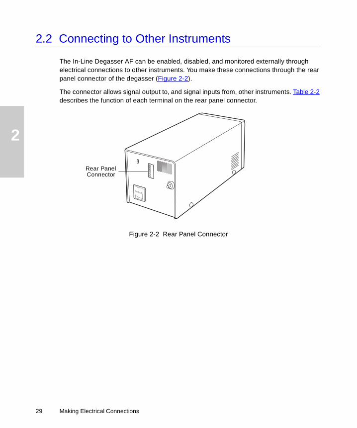
The In-Line Degasser AF can be enabled, disabled, and monitored externally through electrical connections to other instruments. You make these connections through the rear panel connector of the degasser (Figure 2-2).
The connector allows signal output to, and signal inputs from, other instruments. Table 2-2 describes the function of each terminal on the rear panel connector.
Figure 2-2 Rear Panel Connector
Rear PanelConnector
29 Making Electrical Connections

2
2.2.1 Connecting the External Control Terminals
You can control the operation of the In-Line Degasser AF through the External Control terminals on the rear panel:
• An open circuit between the External Control terminals enables the operation of the degasser.
• A switch closure signal applied to the External Control terminals disables the operation of the degasser.
If you do not make connections to the External Control terminals, the In-Line Degasser AF remains in the enabled state when it is powered up.
Table 2-2 Rear Panel Terminals
Connector Function Refer to
External Control(+ and –)
A switch closure signal applied to these terminals disables the operation of the In-Line Degasser AF. A switch open signal applied to these terminals enables the operation of the In-Line Degasser AF.
Section 2.2.1, Connecting the External Control Terminals
Chassis ground. N/A
Vacuum(+ and –)
Provides a dc voltage output that is proportional to the vacuum in the degasser.
Section 2.2.2, Vacuum Terminals
Chassis ground. N/A
STOPAttention: To meet the regulatory requirements of immunity from external electrical disturbances that may affect the performance of this instrument, do not use cables longer than 9.8 feet (3 meters) when you make connections to the screw-type barrier terminal strips. In addition, ensure you always connect the shield of the cable to chassis ground at one instrument only.
Connecting to Other Instruments 30

2
Enabled Mode
When you enable the In-Line Degasser AF (when it is powered up), the power-up sequence begins, as described in Section 4.1, Powering Up. The sequence includes an initial vacuum pump-down cycle followed by continuous operation at low RPM to maintain the vacuum.
Disabled Mode
When you disable the In-Line Degasser AF, the vacuum pump stops. The In-Line Degasser AF remains disabled until an open circuit signal is applied to the terminals.
You can send enable and disable signals to the In-Line Degasser AF from a Waters 600 Series Controller that is connected to the In-Line Degasser AF.
Connecting a Waters 600 Series Controller
To connect a Waters 600 Series Controller to the External Control terminals:
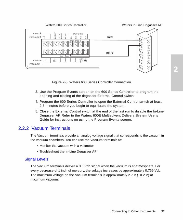
1. Use a signal cable (included in the Startup Kit) to make the connections between the In-Line Degasser AF and a Waters 600 Series Controller as indicated in the following table and illustrated in Figure 2-3.
2. Connect the shield of the cable to chassis ground at one end only. This minimizes the chance of creating a ground loop, which can adversely affect system performance.
Degasser Terminal 600 Series Controller
Terminal
Ext. Control (+) S1, S2, S3, or S4
Ext. Control (–) Gnd
Gnd Do not connect
31 Making Electrical Connections
2
Figure 2-3 Waters 600 Series Controller Connection3. Use the Program Events screen on the 600 Series Controller to program the opening and closing of the degasser External Control switch.
4. Program the 600 Series Controller to open the External Control switch at least 2.5 minutes before you begin to equilibrate the system.
5. Close the External Control switch at the end of the last run to disable the In-Line Degasser AF. Refer to the Waters 600E Multisolvent Delivery System User’s Guide for instructions on using the Program Events screen.
2.2.2 Vacuum Terminals
The Vacuum terminals provide an analog voltage signal that corresponds to the vacuum in the vacuum chambers. You can use the Vacuum terminals to:
• Monitor the vacuum with a voltmeter
• Troubleshoot the In-Line Degasser AF
Signal Levels
The Vacuum terminals deliver a 0.5 Vdc signal when the vacuum is at atmosphere. For every decrease of 1 inch of mercury, the voltage increases by approximately 0.759 Vdc. The maximum voltage on the Vacuum terminals is approximately 2.7 V (±0.2 V) at maximum vacuum.
Waters In-Line Degasser AF
INJE
CT
ST
OP
FLO
W
HO
LD
S1
S2
S3
S4
SWITCHESCHART+PRESSURE+
CHART_
PRESSURE_ G
ND
GN
D
GN
D
GN
D
AU
X.
+12
V
Waters 600 Series Controller
Red
Black
Connecting to Other Instruments 32

2
Note: The In-Line Degasser AF uses an absolute type pressure sensor. Earlier versions of the In-Line Degasser used a relative type pressure sensor. The absolute and relative sensor types produce different signal readings for the same pressure value. Figure 2-4 compares the vacuum terminal signal output of the In-Line Degasser AF to the In-Line Degasser.
Figure 2-4 Comparison of Vacuum Terminal Signal Output
STOPAttention: In some cases, the In-Line Degasser is updated by replacing the entire internal mechanism with that of the In-Line Degasser AF. If your degasser has been updated in this manner, the vacuum terminal signal output will reflect the absolute type pressure sensor of the In-Line Degasser AF.
Pressure
0
0
psi (Absolute)5 10
0
Sig
nal
(V
)
.5
1.0
1.5
2.0
2.5
3.0
3.5
15
4 8 12 16 20 24 28 32 Inches Hg
In-Line Degasser AF
In-Line Degasser
Key
33 Making Electrical Connections

2
Procedure
To connect a voltmeter to the Vacuum terminals:
1. Use a signal cable or the voltmeter leads to make the connections between the In-Line Degasser AF and a voltmeter, as indicated in the following table.
2. Set the voltmeter to the 5 Vdc range. Refer to Chapter 5, Troubleshooting and Service, for further details on using the Vacuum terminals for troubleshooting.
Degasser Terminal Voltmeter
Vacuum (+) (+)
Vacuum (–) (–)
Gnd Not connected
Connecting to Other Instruments 34

3
Chapter 3Making Fluidic Connections
This chapter describes how to make fluidic connections between the Waters In-Line Degasser AF and:
• Waters 600 Series Pumps
• Waters 510 and 515 HPLC Pumps
• Waters 1515 and 1525 HPLC Pumps
• Non-Waters pumps
Required Materials
To make fluidic connections to the In-Line Degasser AF, you need the following materials:
• Tubing cutter as appropriate for the type of tubing: razor knife or blade, or file with a cutting edge
• Tubing: either 1/8-inch outside diameter (od) thick-walled Tefzel® (included in the Startup Kit), or 1/16-inch od stainless steel
• Four ferrules and compression screws (included in the Startup Kit) for each channel
• Tubing, 0.149-inch od TFE1 (included in the Startup Kit)
Assembling Fittings
The fluidic connectors on the front panel of the In-Line Degasser AF are 1/4-28 flat-bottom fittings. The Startup Kit contains a supply of compression screws and ferrules that you use to make connections with these fittings.
To assemble each connection:
1. Use the appropriate tool to cut the tubing to the required length. Make sure the end is straight and free from burrs or debris.
1. Polytetrafluoroethylene
35

3
2. Slide the compression screw over the tubing end, followed by the ferrule, as shown in Figure 3-1. Be sure the tapered end of the ferrule faces away from the end of the tubing.
Figure 3-1 Ferrule and Compression Screw Assembly
Making Connections
To make a tubing connection to the In-Line Degasser AF inlet or outlet:
1. Firmly seat the tubing end in the appropriate fitting.
2. Complete the connection by tightening the compression screw until it is finger-tight.
Pressure Limit
The degassing membrane in the Waters In-Line Degasser AF can withstand a maximum pressure of 10 psi (70 kPa).
Increasing Efficiency
To minimize the equilibration time for the In-Line Degasser AF, fill the degas tubing in any unused vacuum chambers with a fluid such as water or eluent. Install the caps on the inlet and outlet of each fluid-filled chamber to prevent leaks.
STOPAttention: To avoid damaging the ferrule, do not overtighten the compression screw.
STOPAttention: To avoid damaging the In-Line Degasser AF, do not apply more than 10 psi (70 kPa) to the eluent reservoirs.
Tubing
Compression Screw Ferrule
Tubing End (Straight and Smooth)
36 Making Fluidic Connections

3
3.1 Installing with Waters 600 Series Pumps
This section describes how to connect the In-Line Degasser AF in HPLC systems that include any of the following Waters 600 Series Pumps:
• 600
• 616
• 626
Position the In-Line Degasser AF on the right side of the pump, as shown in Figure 3-2. For information about selecting a suitable installation site, refer to Section 1.3, Installation Site Requirements. The In-Line Degasser AF is most effective when the fluid lines from the degasser to the gradient proportioning valve (GPV) or pump inlet are as short as possible. Long sections of polymeric tubing allow ambient gases to dissolve back into the degassed eluents.
Install the In-Line Degasser AF between the eluent reservoirs and the GPV.
Figure 3-2 Positioning the In-Line Degasser AF in a Waters HPLC System
Connecting Inlet Lines
To connect an eluent line from the In-Line Degasser AF to an eluent reservoir:
1. Using the appropriate cutting tool, cut a length of Tefzel tubing (from the Startup Kit) just long enough to reach from the In-Line Degasser AF inlet to the eluent reservoir.
TP01172
Installing with Waters 600 Series Pumps 37

3
2. Install a compression screw and ferrule (from the Startup Kit) to one end of this tubing, as described in the “Assembling Fittings” discussion at the beginning of this chapter.
3. Connect the end of the tubing with the compression screw and ferrule to an available inlet fitting on the In-Line Degasser AF.
4. Insert the other end of the tubing into the cap of the eluent reservoir, as shown in Figure 3-3.
Figure 3-3 Connecting an Inlet Line to the In-Line Degasser AF
5. Install a filter on the end of the tubing.
6. Mark the inlet line with a line marker (A or B, included in the Startup Kit) to identify the reservoir supplying the eluent.
7. Repeat steps 1 through 6 for each eluent line.
38 Making Fluidic Connections

3
Connecting Outlet Lines
To connect an eluent line from the In-Line Degasser AF to the gradient proportioning valve (GPV):
1. Drain any eluent from the eluent line that is connected to the GPV.
2. Using the appropriate tool, cut the eluent line on the pump to a length of approximately 18 inches (45 cm), or long enough to reach the In-Line Degasser AF.
3. Install a compression screw and ferrule (included in the Startup Kit) to the free end of this line, as described in the “Assembling Fittings” discussion at the beginning of this chapter.
4. Connect the free end of the eluent line to the channel outlet (on the front panel of the In-Line Degasser AF) that corresponds to the inlet line of the eluent (Figure 3-4).
Figure 3-4 Connecting an Outlet Line to the In-Line Degasser AF
5. Mark the line with a line marker (A or B, included in the Startup Kit) to identify the reservoir supplying the eluent.
6. Check that the compression screw on the GPV is tight.
7. Repeat steps 1 through 6 for each eluent line.
To Pump
Installing with Waters 600 Series Pumps 39

3
3.2 Installing with Waters 510/515 or 1515/1525 HPLC Pumps
This section describes how to connect the Waters In-Line Degasser AF to the Waters 510/515 or 1515/1525 HPLC Pump.
Position the In-Line Degasser AF on the left side of the pump, as shown in Figure 3-5 and Figure 3-6. Refer to Section 1.3, Installation Site Requirements. The In-Line Degasser AF is most effective when the fluid lines from the In-Line Degasser AF to the draw-off valve inlet are as short as possible. Long sections of polymeric tubing allow ambient gases to dissolve back into the degassed eluents.
Install the in-Line Degasser AF between the eluent reservoir and the draw-off valve inlet to the pump.
Figure 3-5 Positioning the In-Line Degasser AF with the Waters 510 or 515 Pump (515 Shown)
TP01771
ELUENTIN
ELUENTOUT
40 Making Fluidic Connections

3
Figure 3-6 Positioning the In-Line Degasser AF with the Waters 1515 or 1525 PumpConnecting Inlet Lines
To connect an eluent line from the In-Line Degasser AF to an eluent reservoir:
1. Disconnect the eluent tubing from the fitting on the pump draw-off valve inlet.
2. Using the appropriate cutting tool, cut off approximately 1 inch (2.5 cm) from the end of the tubing.
3. Attach a compression screw and ferrule (included in the Startup Kit) to the end of this tubing as described in the “Assembling Fittings” discussion at the beginning of this chapter.
4. Connect this end of the tubing to the inlet of an available channel on the front panel of the degasser (Figure 3-7).
TP01770
ELUENTIN
ELUENTOUT
Installing with Waters 510/515 or 1515/1525 HPLC Pumps 41

3
Figure 3-7 Connecting an Inlet Line to the In-Line Degasser AF5. Mark the line with a marker (A or B, included in the Startup Kit) to identify the reservoir supplying the eluent.
Connecting Outlet Lines
To connect an eluent line from the In-Line Degasser AF to the draw-off valve inlet of the pump:
1. Using the appropriate cutting tool, cut a length of Tefzel tubing (from the Startup Kit) long enough to reach from the In-Line Degasser AF to the draw-off valve inlet of the pump.
2. Attach a compression screw and ferrule (included in the Startup Kit) to one end of this tubing, as described in the “Assembling Fittings” discussion at the beginning of this chapter.
3. Connect this fitting to the channel outlet (on the front panel of the In-Line Degasser AF) that corresponds to the inlet line of the eluent (Figure 3-8).
42 Making Fluidic Connections

3
Figure 3-8 Connecting an Outlet Line to the In-Line Degasser AF4. Mark the line with a line marker (A or B, included in the Startup Kit) to identify the reservoir supplying the eluent.
5. Cut a piece of 0.149-inch od TFE tubing (from the Startup Kit) approximately 2 inches (5 cm) long.
6. Insert the other end of the tubing halfway into the TFE tubing.
7. Slide the TFE tubing over the fitting of the draw-off valve inlet on the pump.
3.3 Installing with Non-Waters Pumps
This section describes how to connect the In-Line Degasser AF to a non-Waters pump.
Locate the In-Line Degasser AF on the side of the pump closest to the eluent inlet of the pump. The In-Line Degasser AF is most effective when the fluid lines from the eluent reservoirs and to the pump are as short as possible. Long sections of tubing allow ambient gases to dissolve back into the degassed eluents.
To Pump
Installing with Non-Waters Pumps 43

3
Install the In-Line Degasser AF between the eluent reservoirs and the pump inlet. Use the Tefzel tubing, compression screws, and ferrules in the Startup Kit to make connections to the In-Line Degasser AF. Use the fittings provided by the pump manufacturer to ensure leak-free connections to the pump.
3.4 Installing the Vent Line
In addition to removing dissolved gases from the eluents, the In-Line Degasser AF may remove some eluent components as vapor. These vapors may condense to form droplets in the exhaust system. The In-Line Degasser AF exhausts these gases and droplets, if any, through a vent fitting on the rear panel, as shown in Figure 3-9. This section describes how to safely vent these emissions.
Figure 3-9 Vent Fitting on Rear Panel
To install the gas/vapor vent:
1. Use a length of 1/8-inch id thick-wall tubing long enough to reach from the rear of the In-Line Degasser AF to an appropriate exhaust system.
The Startup Kit contains a 15-foot (4.5 m) length of FEP-lined1 PVC2 tubing for this purpose. If you need additional tubing, see Appendix B, Spare Parts for the Waters part number.
Caution: To avoid contact with eluent gases, connect the outlet vent to a suitable exhaust system, such as a properly functioning fume hood.
Vent Fitting
44 Making Fluidic Connections
3
2. Attach one end of the tubing to the barbed vent fitting on the rear panel.
3. Place the other end of the tubing in a waste container in the venting outlet. This container catches any incidental leaks or condensates from the In-Line Degasser AF.
1. Fluoroethylene propylene copolymer2. Polyvinyl chloride
Installing the Vent Line 45

4
Chapter 4Using the In-Line Degasser AF
This chapter describes how to use the Waters In-Line Degasser AF after it has been successfully installed. The topics covered in this chapter describe:
• Powering up the In-Line Degasser AF
• Degasser operation
• Controlling the In-Line Degasser AF from an external source
• Powering down the In-Line Degasser AF
4.1 Powering Up
Before Powering Up
Before you power up the In-Line Degasser AF, make sure that:
• Correct fuses are installed
• The power cable is connected
• Eluent tubing is correctly connected to the eluent reservoirs and the pump(s)
• The vent line is properly installed
Powering Up
To power up the In-Line Degasser AF:
1. Push the Power switch on the front panel to the On (I) position. The LED on the front panel lights, and the following events occur:
a. The vacuum pump starts.
b. The vacuum chambers pump down.
c. The vacuum pump switches to low-speed mode.
The vacuum pump begins operating after a few seconds, and pumps down the vacuum chambers for approximately two minutes. At the end of the pump-down cycle, the vacuum pump switches to low-speed mode. The In-Line Degasser AF is ready for operation when the LED on the front panel is a steady green color.
Powering Up 46

4
If the vacuum is not within specification, the LED on the front panel flashes on and off. If this occurs, refer to Chapter 5, Troubleshooting and Service, to identify and correct the problem.
2. Start the HPLC pump and begin your chromatography.
Note: Start the In-Line Degasser AF at least 2.5 minutes before you start to equilibrate your HPLC system. This provides enough time for the In-Line Degasser AF to reach maximum vacuum. Running the In-Line Degasser AF while you equilibrate the system minimizes baseline noise.
4.2 In-Line Degasser AF Operation
This section describes:
• Operating statuses of the In-Line Degasser AF
• Degassing efficiency
4.2.1 Operating Statuses
The Waters In-Line Degasser AF operates automatically while you perform your HPLC runs. There are no controls to adjust as it removes gases from the eluents.
The LED on the front panel indicates the status of the In-Line Degasser AF. For more information about the operating statuses, see Table 5-1.
47 Using the In-Line Degasser AF

4
4.2.2 Degassing Efficiency
Effect of Flow Rate
The flow rate of eluent through the In-Line Degasser AF determines the efficiency with which the degasser removes gases. As the flow rate increases, the In-Line Degasser AF has less time to remove dissolved gases from the eluent. Table 4-1 shows the relationship between the flow rate of an eluent (water) and the concentration of a gas (oxygen) dissolved in the eluent.
Methods to Improve Degassing Efficiency
If you need to reduce the dissolved gases below the levels shown in Table 4-1 while maintaining the flow rate, you can perform any combination of the following techniques:
• Fill the degas tubing in any unused vacuum chambers with fluid
• Increase the time the eluent is exposed to vacuum by connecting one or more vacuum chambers in series in the In-Line Degasser AF
• Sparge with an inert gas (preferably helium) in addition to using the In-Line Degasser AF
Filling Unused Chambers
If you do not use all the chambers in the In-Line Degasser AF during a run, fill the degas tubing in unused vacuum chambers with a fluid such as water or eluent. Install the caps on the inlet and outlet of each fluid-filled vacuum chamber to prevent leaks. This procedure minimizes the equilibration time for the In-Line Degasser AF.
Table 4-1 Effect of Flow Rate on Final Dissolved Gas Concentration
Flow Rate(mL/min)
Final Oxygen Concentration (ppm)
1 ≤1
2 ≤1.3
5 ≤2.3
In-Line Degasser AF Operation 48

4
Connecting Vacuum Chambers
To connect two or more vacuum chambers in series:
1. Detach the outlet line from the first vacuum chamber.
2. Attach this outlet line to the outlet connector on a second, available vacuum chamber.
3. Using an appropriate cutting tool, cut a new piece of Tefzel tubing (included in the Startup Kit) to a length of approximately 8 inches (20 cm).
4. Install a compression screw and ferrule (included in the Startup Kit) on each end of this tubing.
5. Connect one end of the tubing to the outlet of the first vacuum chamber, as shown in Figure 4-1.
Figure 4-1 Two Vacuum Chambers in Series
6. Connect the other end of the tubing to the inlet of the second vacuum chamber, as shown in Figure 4-1.
7. Repeat steps 1 through 6 if you want to connect more than two vacuum chambers in series.
TP01175
ELUENTIN
ELUENTOUT
To ReservoirTo Pump
49 Using the In-Line Degasser AF

4
Sparging
Helium sparging reduces the total dissolved gas in the eluent reservoirs and maintains this condition during operation. You can sparge the eluents and use the In-Line Degasser AF at the same time. Refer to your pump operator’s manual for specific instructions on connecting sparge lines.
Note: To prevent eluent contamination, use an ultra-pure-carrier (UPC) grade of helium.
The combination of inert gas (nitrogen or helium) sparging and inline degassing is an effective method of reducing dissolved oxygen to the lowest possible level. See Section 1.2.2, Effects of Dissolved Oxygen, for a discussion on the effects of dissolved oxygen.
A combination of helium (not nitrogen) sparging and inline degassing is best at flow rates above 5 mL/min to maintain a minimum concentration of dissolved gases.
Note: Degassing methods must be implemented carefully with eluents containing volatile components. Chromatographic performance may be altered by minor changes in eluent composition.
4.3 Controlling the Degasser Externally
This section describes how to control the Waters In-Line Degasser AF from an external device. Using the External Control terminals on the rear panel, you can place the degasser in either of the following modes:
• Enabled mode
• Disabled mode
Enabled Mode
An open circuit on the External Control terminals on the rear panel of the In-Line Degasser AF places the degasser in the enabled mode. This is the default setting when there are no connections to the terminals.
The following events occur when the In-Line Degasser AF enters the enabled mode, either from a power-up sequence or from a switch open signal to the External Control terminals:
1. The LED on the front panel turns on.
2. The vacuum pump begins a pump-down cycle.
3. Normal operation begins when the pump-down cycle is complete.
Controlling the Degasser Externally 50

4
Disabled Mode
A closed circuit on the External Control terminals on the rear panel of the In-Line Degasser AF places the degasser in the disabled mode.
The following events occur when the In-Line Degasser AF enters the disabled mode from a switch close signal:
1. The vacuum pump turns off.
2. The LED on the front panel flashes yellow (0.5 seconds on and 2 seconds off).
The In-Line Degasser AF remains in the disabled mode until a switch open signal occurs at the External Control terminals.
External Control
You can externally control when the In-Line Degasser AF turns on and off using a switch open and switch close signal from a Waters 600 Series Controller or any other device with contact closure outputs.
You can program a Waters 600 Series Controller to generate a switch open or close signal at a specific time. This signal, when sent to the External Control terminals on the In-Line Degasser AF, automatically enables the degasser to begin the pump-down cycle before the start of a run. The In-Line Degasser AF is then ready to provide degassed eluent when a run is initiated.
Refer to Section 2.2.1, Connecting the External Control Terminals, for the procedure to connect a Waters 600 Series Controller to the In-Line Degasser AF.
4.4 Powering Down
To power down the In-Line Degasser AF, push the Power switch to the Off (0) position. The following events occur when you power down the degasser:
1. The vacuum pump turns off.
2. The LED on the front panel turns off.
51 Using the In-Line Degasser AF

5
Chapter 5Troubleshooting and Service
This chapter describes how to troubleshoot and service problems that may occur with the In-Line Degasser AF. The chapter consists of two sections:
• Troubleshooting, including troubleshooting trees
• Service instructions to use with the troubleshooting trees
Note: Under normal operating conditions, the In-Line Degasser AF requires no routine maintenance.
5.1 Troubleshooting
This section provides information for troubleshooting the In-Line Degasser AF. It covers:
• Vacuum problems
• Electrical problems
Overview
Use the troubleshooting trees in this section to identify and locate problems within the In-Line Degasser AF. The degasser is designed to be serviceable by you. Refer to Section 5.2, Service, for descriptions of the procedures indicated in the troubleshooting trees.
LED Indications
The LED on the front panel indicates the status of the In-Line Degasser AF as described in Table 5-1.
Caution: Always observe safe laboratory practices when you are troubleshooting. Wear safety glasses and gloves. Know the chemical and physical properties of the eluents you are using. Refer to the Material Safety Data Sheet for each eluent in use.
Troubleshooting 52

5
Contacting Waters Technical Service
If you cannot resolve a problem using the troubleshooting information in this chapter, contact Waters Technical Service at (800) 252-4752, U.S. and Canadian customers only. Other customers, call your local Waters subsidiary or your local Waters Technical Service representative, or call Waters corporate headquarters for assistance at (508) 478-2000 (U.S.).
Vacuum Troubleshooting
If you suspect that there is a problem with the In-Line Degasser AF, start with the vacuum troubleshooting tree in Figure 5-1.
Table 5-1 LED Indications
LED State Description
Unlit Unit powered off.
Steady yellow color Unit operating with pump at high RPM, vacuum level above 47 mmHg/0.91 psiA. Usually a brief transitional state during initial pump-down.
Steady green color Unit operating with pump at low RPM, vacuum level below 47 mmHg/0.91 psiA. Typical operating conditions.
Green flash 0.5 seconds on and 0.5 seconds off
Unit operating but vacuum level unstable. Indicates a sudden change in degasser work load.
Yellow flash 0.5 seconds on and 2 seconds off
Unit not operating. External control jumper or contact closure installed on rear panel connector J2. Operation will resume when the jumper or contact closure is removed.
Yellow flash 2 seconds on and 0.5 seconds off
Unit not operating. Vacuum signal out of usable range, indicating an electronic or pressure sensor failure.
Yellow flash 0.5 seconds on and 0.5 seconds off
Unit not operating. Vacuum pump-down level not reached within 10 minutes of power-on or enable. Indicates a vacuum leak.
Alternating yellow and green flash
Unit not operating. Vacuum pump-down level reached but then rose above high limit. Indicates a vacuum failure.
53 Troubleshooting and Service

5
Figure 5-1 Vacuum Troubleshooting TreeLEDStatus
Start
Vacuum Unstable but Degasser OK
Off
Flashing
Flashing Green
Remove Cover
Yes
No
No
Yes
SensorGood?
Purge Eluent
Yes
from Vacuum
Continued
Power UpPowerOn?
Is Eluentin Vacuum
No
Yes
Replace Control
Pump
Tubing?
Tubing
Drain Eluent from Chambers
DisconnectEluent Tubing
Good?
Test VacuumSensor
Test Pump for
PCB Assembly
Replace Pump
Vacuum Leaks
No
Degasser
No
YesYes
No
IsDegasserDisabled?
.5 Sec On,2 SecOff?
Is Flash
DegasserEnable
Yellow
Go to Electrical Troubleshooting Tree (Figure 5-2)
Troubleshooting 54

5
Figure 5-1 Vacuum Troubleshooting Tree (Continued)
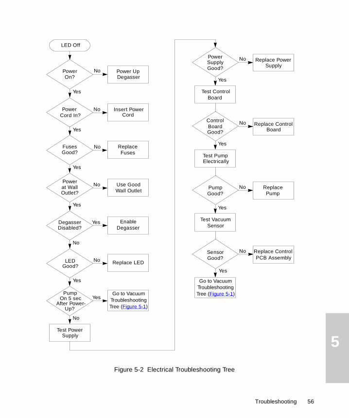
Electrical Troubleshooting
Use the electrical troubleshooting tree in Figure 5-2 if the LED on the front panel of the In-Line Degasser AF does not light when you power up the degasser. The electrical troubleshooting tree helps you identify electrical problems in the following components:
• Power supply
• Control board
• Vacuum pump
Test VacuumTubing
No Replace
Yes
TubingGood?
Call WatersService
Continued
Test VacuumChambers
No Replace Chamber
Yes
ChamberGood?
Tubing
55 Troubleshooting and Service
5
Figure 5-2 Electrical Troubleshooting Tree
No
Yes
LED Off
No
Yes
Power Insert PowerCord
No
Yes
PowerOn?
Power UpDegasser
Cord In?
No
Yes
Test PowerSupply
No
Yes
PowerSupply Replace Power
SupplyGood?
Test ControlBoard
No
Yes
ControlBoard Replace Control
BoardGood?
Test Pump
No
Yes
Pump Replace PumpGood?
Test Vacuum
No
Yes
Sensor
Replace ControlPCB AssemblyGood?
Sensor
Fuses Replace Fuses
No
Yes
PowerUse GoodWall Outlet
No
Yes EnableDegasser
DegasserDisabled?
Good?
at WallOutlet?
Electrically
No
YesPump
On 5 secAfter Power-
Up?
LEDGood?
Replace LED
Sensor
Go to Vacuum Troubleshooting Tree (Figure 5-1)
Go to Vacuum Troubleshooting Tree (Figure 5-1)
Troubleshooting 56

5
5.2 Service
The Waters In-Line Degasser AF is designed to be serviced by you, the customer. The troubleshooting trees in Section 5.1, Troubleshooting, describe the sequence of procedures to follow to identify a malfunctioning component. This section describes how to perform the procedures indicated in the troubleshooting tree.
Required Tools
Use the following tools to service the In-Line Degasser AF:
• Phillips screwdriver
• 1/4-inch open-end wrench or adjustable wrench
• Syringe, 10-mL
• Tubing cutter, razor knife, or razor blade
• TORX™ TX-10 and TX-20 screwdrivers (1 each)
• Eluent waste container
• Volt-ohmmeter or voltmeter and ohmmeter
5.2.1 Removing and Installing the Cover
Removing the Cover
To remove the In-Line Degasser AF cover:
1. Power down the In-Line Degasser AF and remove the power cord from the receptacle on the rear panel.
2. Using a Phillips screwdriver, loosen the four screws located on the lower four corners of the cover. You do not have to remove the screws.
3. Slide the cover straight up and off the chassis.
Caution: To avoid possible electric shock, do not open the power supply cover. The power supply does not contain user-serviceable components.
Caution: To avoid possible electric shock, ensure that the degasser is powered down and the power cord is disconnected before proceeding.
57 Troubleshooting and Service

5
Installing the Cover
To install the cover:
1. Slide the cover over the chassis. The screw slots are keyed to ensure that you install the cover correctly.
2. Using the Phillips screwdriver, tighten the four screws located on the lower four corners of the cover.
3. Insert the power cord into the receptacle on the rear panel.
5.2.2 Disconnecting Eluent Lines
To disconnect the eluent lines:
1. Place the eluent reservoir below the level of the inlet fitting on the In-Line Degasser AF.
2. Loosen the inlet compression screw on the In-Line Degasser AF. The eluent in the tubing drains into the reservoir.
3. Remove the inlet tubing from the In-Line Degasser AF.
4. Return the eluent reservoir to its normal position.
5. Remove the outlet fitting on the In-Line Degasser AF or the inlet fitting on the pump, whichever is higher.
6. Drain the tubing into a suitable waste container.
7. Remove the outlet fitting on the In-Line Degasser AF or the inlet fitting on the pump.
5.2.3 Purging the Eluent Tubing in Vacuum Chambers
To purge the eluent tubing in a vacuum chamber:
1. Place the eluent reservoir below the level of the inlet fitting on the In-Line Degasser AF.
Caution: Always observe safe laboratory practices when handling eluents. Wear safety glasses and gloves. Know the chemical and physical properties of the eluents you are using. Refer to the Material Safety Data Sheet for each eluent in use.
Caution: Always observe safe laboratory practices when handling eluents. Wear safety glasses and gloves. Know the chemical and physical properties of the eluents you are using. Refer to the Material Safety Data Sheet for each eluent in use.
Service 58

5
2. Disconnect the eluent inlet line and let the eluent drain into the reservoir.
3. Remove the outlet fitting on the In-Line Degasser AF or the inlet fitting on the pump, whichever is higher.
4. Drain the tubing into a suitable waste container.
5. Remove the outlet fitting on the In-Line Degasser AF if you did not disconnect it in step 3.
6. Attach a short piece (at least 2 cm) of tubing to the outlet fitting on the In-Line Degasser AF.
7. Insert a syringe into the tubing and draw out any remaining eluent. The eluent tubing in the vacuum chamber holds approximately 8 mL of eluent.
5.2.4 Draining the Vacuum Tubing and Chambers
If the eluent tubing inside a vacuum chamber develops a leak, eluent can accumulate in the vacuum chambers and vacuum tubing. When this occurs, you need to drain eluent from the vacuum system.
If you find eluent in more than one vacuum chamber, do not assume that all the chambers are faulty. Test each vacuum chamber separately. Refer to Section 5.2.9, Testing the Vacuum Chambers, for the procedure for testing a vacuum chamber.
Before you test each vacuum chamber, drain any eluent from the vacuum tubing and vacuum chambers using the procedures that follow.
Draining the Vacuum Tubing
To drain the eluent in the vacuum tubing:
1. Power down the In-Line Degasser AF and remove the power cord from the receptacle on the rear panel.
2. Remove the eluent lines from the front panel of the In-Line Degasser AF as described in Section 5.2.2, Disconnecting Eluent Lines.
Caution: Always observe safe laboratory practices when handling eluents. Wear safety glasses and gloves. Know the chemical and physical properties of the eluents you are using. Refer to the Material Safety Data Sheet for each eluent in use.
Caution: To avoid possible electric shock, ensure that the degasser is powered down and the power cord is disconnected before proceeding.
59 Troubleshooting and Service

5
3. Remove the cover as described in Section 5.2.1, Removing and Installing the Cover.
4. Locate a section of vacuum tubing that contains no eluent.
5. Disconnect the end of the tubing at the connection farthest from the eluent.
6. Insert a syringe into the tubing and draw out the eluent.
7. Cut off 1/4 to 1/2 inch from the free end of each tubing, or replace the vacuum tubing. This ensures airtight connections.
8. Reconnect the vacuum tubing.
9. Reinstall the cover as described in Section 5.2.1, Removing and Installing the Cover.
Draining the Vacuum Chambers
To drain a vacuum chamber:
1. Power down the In-Line Degasser AF and remove the power cord from the receptacle on the rear panel.
2. Remove the eluent lines from the front panel of the In-Line Degasser AF as described in Section 5.2.2, Disconnecting Eluent Lines.
3. Remove the cover as described in Section 5.2.1, Removing and Installing the Cover.
4. Drain the eluent in the eluent tubing as described in Section 5.2.3, Purging the Eluent Tubing in Vacuum Chambers.
5. Drain any eluent in the vacuum tubing as described earlier in “Draining the Vacuum Tubing”.
6. Disconnect the vacuum tubing from the chamber.
7. Lift the rear of the vacuum chamber, unsnapping it from the mounting bracket. Remove the vacuum chamber from the chassis.
8. Use a wrench to remove the 1/4-inch plug on the front panel of the vacuum chamber.
9. Drain the eluent in the chamber into a suitable waste container. Replace the plug.
10. Reinstall the chamber into the chassis.
11. Cut off 1/4 to 1/2 inch from the end of each tubing, or replace the vacuum tubing. This ensures airtight connections.
Caution: To avoid possible electric shock, ensure that the degasser is powered down and the power cord is disconnected before proceeding.
Service 60

5
12. Reconnect the vacuum tubing.
13. Reinstall the cover as described in Section 5.2.1, Removing and Installing the Cover.
5.2.5 Testing the Vacuum Sensor
The vacuum sensor is mounted on the control board assembly. To test the vacuum sensor:
1. Power down the In-Line Degasser AF and remove the power cord from the receptacle on the rear panel.
2. Remove the cover as described in Section 5.2.1, Removing and Installing the Cover.
3. Connect a voltmeter to the Vacuum Level terminals on the rear panel as described in Section 2.2.2, Vacuum Terminals. Set the voltmeter to the 5 Vdc range.
4. Disconnect the sensor tubing at the vacuum manifold as shown in Figure 5-3.
5. Insert the power cable into the receptacle on the rear panel. Power up the In-Line Degasser AF. The voltmeter should read 0.5 V until the pump starts.
Figure 5-3 Testing the Vacuum Sensor
STOPAttention: To avoid damage to the sensor, use great care when you remove and install the sensor tubing. The sensor tubing is FEP-lined Tygon with an FEP insert. If you need to replace this tubing, use only the correct part number. Refer to Appendix B, Spare Parts, for the correct part number.
RearVacuum
ControlBoard
PumpPanel Panel
Front
PowerSupply
Syringe
VacuumManifold
61 Troubleshooting and Service

5
6. Insert a syringe into the open tubing. Make sure the syringe seals against the tubing.
7. Monitor the vacuum signal on the voltmeter while you draw out the plunger of the syringe. (You should feel resistance as you withdraw the syringe.) If the voltage increases as you draw out the plunger, the sensor is functioning properly. Go to step 8.
If the voltage remains at 0.5 V as you draw out the plunger, the vacuum sensor is faulty. Disconnect power and replace the control board assembly as described in Section 5.2.7, Testing the Control Board Assembly. The part number for the Control Board is listed in Appendix B, Spare Parts.
8. Cut a 1/4- to 1/2-inch length from the end of the tubing. This ensures an airtight connection.
9. Reconnect the tubing.
10. Reinstall the cover as described in Section 5.2.1, Removing and Installing the Cover.
11. Insert the power cable into the receptacle on the rear panel.
5.2.6 Testing the Power Supply
Before you test the power supply, verify that:
• Power is on
• Degasser is enabled (no connection to External Control terminals on rear panel)
• Fuses are good
To test the power supply:
1. Power down the In-Line Degasser AF and remove the power cord from the receptacle on the rear panel.
2. Remove the cover as described in Section 5.2.1, Removing and Installing the Cover.
3. Remove the power connector from the power connector receptacle on the control board, as shown in Figure 5-4.
Caution: To avoid possible electric shock, use extreme caution when testing the power supply. If you have any doubts about your ability to safely test the power supply, contact your Waters Technical Service representative.
Service 62

5
Figure 5-4 Power Connector Receptacle on Control Board Assembly
4. Insert the voltmeter leads into the connector:
• Place the positive lead into the connector terminal with the red wire.
• Place the negative lead into the connector terminal with the black wire.
5. Set the voltmeter to the 20 Vdc range.
6. Insert the power cable into the receptacle on the rear panel.
7. Power up the In-Line Degasser AF. Check that the voltmeter reads 15 V ±0.75 V. If the voltage is within this range, the power supply is functioning properly. Go to step 8.
If the voltage is above 15.75 V or below 14.25 V, the power supply is faulty. Replace the power supply as described next in “Replacing the Power Supply”.
8. Reinstall the power connector into the power receptacle on the control board.
9. Reinstall the cover as described in Section 5.2.1, Removing and Installing the Cover.
10. Insert the power cord into the receptacle on the rear panel.
Power Connector Receptacle
63 Troubleshooting and Service

5
Replacing the Power Supply
If the power supply is faulty, use the following procedure to replace the power supply:
1. Power down the In-Line Degasser AF and remove the power cord from the receptacle on the rear panel.
2. Remove the two M3 x 6 TORX screws on the bottom panel and the M3 x 6 TORX screw on the rear panel.
3. Lift the power supply out of the chassis. The control board remains attached to the supply.
4. Remove the three M3 x 6 TORX screws that secure the cover of the housing.
5. Remove the cover.
6. Remove the two connectors on the power supply board inside the housing.
7. Remove the four M3 x 6 TORX screws that secure the power supply board to the housing. The screw in the lower-left corner has a star washer beneath it.
8. Remove the power supply board from the power supply housing.
9. Install the new power supply board into the housing.
10. Install the four M3 x 6 TORX screws and one star washer that secure the power supply board to the housing.
11. Reinstall the two connectors to the power supply board.
12. Reinstall the housing cover. Install the three M3 x 6 TORX screws securing the cover.
13. Reinstall the power supply housing into the chassis.
14. Install the two M3 x 6 TORX screws on the bottom panel and the M3 x 6 TORX screw on the rear panel securing the housing to the chassis.
15. Reinstall the power connector on the control board.
16. Reinstall the cover as described in Section 5.2.1, Removing and Installing the Cover.
17. Insert the power cord into the receptacle on the rear panel.
Caution: To avoid possible electric shock, ensure that the degasser is powered down and the power cord is disconnected before proceeding.
Service 64

5
5.2.7 Testing the Control Board Assembly
Test the control board assembly after you have determined that the power supply is operating properly. To verify that the control board is working correctly, you need to check:
• LED
• Vacuum pump
To test the control board:
1. Power up the In-Line Degasser AF.
2. Check that the LED on the front panel lights up.
3. Check that the vacuum pump turns on after a few seconds. If the LED lights up and the vacuum pump turns on, the control board is functioning properly.
If the LED does not light up or the vacuum pump does not turn on, the control board is faulty. Replace the control board as described next in “Replacing the Control Board”.
Replacing the Control Board
If the control board is faulty, use the following procedure to replace the control board:
1. Power down the In-Line Degasser AF and remove the power cord from the receptacle on the rear panel.
2. Place the new control board next to the old control board.
3. Remove each connector from its receptacle on the old control board and reconnect it to the corresponding receptacle on the new control board.
Caution: To avoid possible electric shock, do not open the power supply cover. The power supply does not contain user-serviceable components.
Caution: To avoid possible electric shock, ensure that the degasser is powered down and the power cord is disconnected before proceeding.
STOPAttention: To avoid damage to the sensor, use great care when you remove and install the sensor tubing. The sensor tubing is FEP-lined Tygon with an FEP insert. If you need to replace this tubing, use only the correct part number. Refer to Appendix B, Spare Parts, for the correct part number.
65 Troubleshooting and Service

5
4. Remove the sensor tubing from the old control board and install it on the new control board.
5. Remove the M3 x 6 TORX screw and M3 star washer from the upper-left corner of the old control board.
6. Press the old control board off the posts at the other three corners.
7. Press the new control board onto the posts.
8. Reinstall the M3 x 6 TORX screw and M3 star washer in the upper-left corner of the control board.
9. Reinstall the cover as described in Section 5.2.1, Removing and Installing the Cover.
10. Insert the power cord into the receptacle on the rear panel.
5.2.8 Testing the Vacuum Pump
Test the vacuum pump after you have determined that the vacuum valve, vacuum sensor, power supply, and the control board assembly are operating properly.
Vacuum Test
After performing the electrical test, test for vacuum leaks:
1. Power down the In-Line Degasser AF and remove the power cord from the receptacle on the rear panel.
2. Remove the cover as described in Section 5.2.1, Removing and Installing the Cover.
3. Connect the voltmeter to the Vacuum terminals on the rear panel. See Section 2.2.2, Vacuum Terminals, for the procedure.
4. Connect the vacuum tubing from the pump directly to the control board assembly as shown in Figure 5-5.
Caution: To avoid possible electric shock, do not open the power supply cover. The power supply does not contain user-serviceable components.
Caution: To avoid possible electric shock, ensure that the degasser is powered down and the power cord is disconnected before proceeding.
Service 66

5
Figure 5-5 Vacuum Connections to Test the Vacuum Pump
5. Insert the power cable into the receptacle on the rear panel.
6. Power up the In-Line Degasser AF.
7. Monitor the vacuum signal on the voltmeter. If the voltage signal increases smoothly and stabilizes, the vacuum pump is in good condition. Go to step 8.
If the voltage signal is unstable or remains at 0.5 V, the vacuum pump is faulty. Replace the motor-pump assembly as described in “Replacing the Vacuum Pump”.
8. Reconnect the tubing to the original configuration. Before reconnecting, cut off 1/4 to 1/2 inch from the end of each tubing, or replace the vacuum tubing. This ensures airtight connections.
9. Reinstall the cover as described in Section 5.2.1, Removing and Installing the Cover.
10. Insert the power cord into the receptacle on the rear panel.
Replacing the Vacuum Pump
If the diagnostic flowchart indicates that the vacuum pump is faulty, use the following procedure to replace the pump:
Caution: To avoid possible electric shock, do not open the power supply cover. The power supply does not contain user-serviceable components.
RearVacuum
ControlBoard
PumpPanel PanelFront
PowerSupply
67 Troubleshooting and Service

5
1. Power down the In-Line Degasser AF and remove the power cord from the receptacle on the rear panel.
2. Remove the vacuum tubing from the old pump.
3. Remove the pump connector from the control board.
4. Remove the three M4 x 16 screws securing the pump to the chassis. Remove the pump.
5. Install the new pump, securing it to the chassis with the three M4 x 16 screws.
6. Install the new pump connector on the control board.
7. Reconnect the vacuum tubing to the new pump. Before reconnecting, cut off 1/4 to 1/2 inch from the end of each tubing, or replace the vacuum tubing. This ensures airtight connections.
8. Reinstall the cover as described in Section 5.2.1, Removing and Installing the Cover.
9. Insert the power cord into the receptacle on the rear panel.
5.2.9 Testing the Vacuum Chambers
If you suspect that there is a vacuum leak in a vacuum chamber, perform the test in this section. If there is eluent in the chamber or in the tubing, remove the eluent using the procedures in Section 5.2.4, Draining the Vacuum Tubing and Chambers. You do not need to remove the eluent lines on the front panel to perform this test.
1. Power down the In-Line Degasser AF and remove the power cord from the receptacle on the rear panel.
2. Remove the cover as described in Section 5.2.1, Removing and Installing the Cover.
Caution: To avoid possible electric shock, ensure that the degasser is powered down and the power cord is disconnected before proceeding.
Caution: To avoid possible electric shock, do not open the power supply cover. The power supply does not contain user-serviceable components.
Caution: To avoid possible electric shock, ensure that the degasser is powered down and the power cord is disconnected before proceeding.
Service 68

5
3. Connect the voltmeter to the Vacuum terminals on the rear panel. See Section 2.2.2, Vacuum Terminals, for the procedure. Set the voltmeter on the 5 Vdc range.
4. Identify the vacuum chamber you want to test, then disconnect the remaining vacuum chambers from the vacuum manifold. Plug the open ends of the vacuum manifold with wooden pencils or other tapered objects as shown in Figure 5-6.
Figure 5-6 Vacuum Connections to Test a Vacuum Chamber
5. Insert the power cable into the receptacle on the rear panel.
6. Power up the In-Line Degasser AF.
7. Monitor the vacuum signal on the voltmeter. If the voltage signal increases smoothly and stabilizes, the vacuum chamber is in good condition. Repeat steps 4 through 7 to test another chamber, or proceed to step 8.
If the voltage signal is unstable or remains at 0.5 V, the vacuum chamber is faulty. Replace the vacuum chamber as described in Section 5.2.10, Replacing a Vacuum Chamber.
8. Reconnect the tubing to the original configuration. Before reconnecting, cut off 1/4 to 1/2 inch from the free end of each tubing, or replace the vacuum tubing. This ensures airtight connections.
9. Power down the In-Line Degasser AF and remove the power cable from the receptacle on the rear panel.
10. Reinstall the cover as described in Section 5.2.1, Removing and Installing the Cover.
11. Insert the power cord into the receptacle on the rear panel.
Rear
Vacuum
ControlBoard
Pump
Panel Panel
Front
PowerSupply
Plug
69 Troubleshooting and Service

5
5.2.10 Replacing a Vacuum Chamber
To replace a faulty vacuum chamber:
1. Remove the eluent lines as described in Section 5.2.2, Disconnecting Eluent Lines.
2. Purge the vacuum chamber of eluent as described in Section 5.2.3, Purging the Eluent Tubing in Vacuum Chambers.
3. Drain the vacuum tubing and/or vacuum chamber (if necessary), as described in Section 5.2.4, Draining the Vacuum Tubing and Chambers.
4. Disconnect the vacuum manifold from the rear of the vacuum chamber.
5. Lift the rear of the vacuum chamber, unsnapping it from the mounting bracket. Remove the vacuum chamber from the chassis.
6. Mount the new vacuum chamber on the locating pin on the inside of the front panel.
7. Snap the rear of the vacuum chamber into the mounting bracket.
8. Reconnect the vacuum manifold to the vacuum chamber.
9. Reinstall the cover as described in Section 5.2.1, Removing and Installing the Cover.
10. Reconnect the eluent lines.
11. Insert the power cord into the receptacle on the rear panel.
Vacuum Tubing Schematics
Table 5-2 summarizes the schematics for the vacuum tubing inside the In-Line Degasser AF. Use these schematics as a guide for replacing the vacuum tubing. The tubing lengths shown in the figures are approximate.
Table 5-2 Tubing Schematics
Number of Chambers Refer to
2 Figure 5-7
3 Figure 5-8
4 Figure 5-9
Service 70

5
Figure 5-7 Vacuum Tubing Schematic for a Degasser with Two Vacuum Chambers
Figure 5-8 Vacuum Tubing Schematic for a Degasser with Three Vacuum Chambers
RearVacuum
ControlBoard
PumpPanel Panel
Front
PowerSupply
Rear
Vacuum
ControlBoard
PumpPanel Panel
Front
PowerSupply
71 Troubleshooting and Service

5
Figure 5-9 Vacuum Tubing Schematic for a Degasser with Four Vacuum Chambers
Rear
Vacuum
ControlBoard
PumpPanel Panel
Front
PowerSupply
Service 72

A
Appendix ASpecificationsThis appendix lists the operational specifications of the In-Line Degasser AF.
Table A-1 Operational Specifications
Item Specification
Chemical resistance Unaffected by full range of organic solvents and aqueous solutions of acids, bases, salts, and surfactants
pH range 0 to 14
Gas removal efficiency Varies with flow rate (see Table 4-1)
Typical operating flow range 200 µL/min to 5 mL/min
Equilibration time <1 hour
Pressure drop (across one channel) <0.08 psi (0.55 kPa) at 1 mL/min., Milli-Q® water, STP
Wetted surfaces PPSa, Teflon AFb, Tefzelc
Inputs Enable, Disable (External control)
Output dc voltage (Relative vacuum)
Eluent connections 1/4-28 reversed ferrule fittings;4 inlet and 4 outlet fittings
Vacuum chambers One chamber/eluent, two channels standard, third or fourth channel optional;<0.5 mL internal volume/channel
Tubular membrane 1/vacuum chamber, Teflon AF
Vapor exhaust 1/8-inch (3 mm) barbed fitting
73

A
Vacuum source Built-in 2-head diaphragm pump, solvent resistantVacuum sensor Detects vacuum from 0 to 15.6 psiA
Maximum pressure on inlet and outlets 10 psi (70 kPa)
Dimensions Width: 5.25 inches (13.33 cm)
Height: 5.75 inches (14.60 cm)
Depth: 12.0 inches (30.48 cm)
Weight 7.5 pounds (3.4 kg)
Power requirement 115 Vac (85 to 132 V), 50/60 Hz
230 Vac (187 to 264 V), 50/60 Hz
Autosensing
Ambient temperature 4 to 40 °C (39 to 104 °F)
Relative humidity 10 to 90%, noncondensing
a High-Density Polyethyleneb Polytetrafluoroethylenec Ethylenetetrafluoroethylene
Table A-1 Operational Specifications (Continued)
Item Specification
74

B
Appendix BSpare Parts
The following spare parts are recommended for customer installation. Use the number in the Recommended Stock column as a guide to the quantity of each item to keep on hand.
Table B-1 Spare Parts
ItemRecommended
StockPart Number
Vacuum Chamber 0 700001218
Vacuum Manifold Tube Assembly with Sipper 0 700001333
Vacuum Tube Replacement Kit 0 WAT073630
Control Board 0 700001351
Vacuum Pump 0 700001352
LED Assembly, Multi Colored 0 700001353
Power Supply 0 WAT034507
Fuse Drawer 0 WAT079711
Compression Screw, 1/8-inch, package of 5 1 WAT037372
Ferrule, 1/8-inch, yellow, package of 5 1 WAT037373
Tubing, Tygon, 2 feet 0 WAT079794
Tubing, Tygon, 0.125 in x 0.25 in, 50 feet 1 WAT079731
Terminal Connector, 6 Pin 0 WAT057241
Fuse, 1.6 A, UL/CSA, time delay, package of 5 1 WAT079713
Fuse, 1.6 A, IEC, time delay, package of 5 1 WAT079716
75

B
Waters In-Line Degasser AF Operator’s Guide 0 71500030802
Startup Kit 0 WAT079718
Table B-1 Spare Parts (Continued)
ItemRecommended
StockPart Number
76

X
I
D
X
NI
DEX
N
Index
CConnecting
external control terminals 30inlet lines, 510/515 and 1515/1525
Pumps 41inlet lines, 600 Series Pumps 37outlet lines, 510/515 and 1515/1525
Pumps 42outlet lines, 600 Series Pumps 39Waters 600 Series Controller 31
Connectionsmaking electrical 29making fluidic 36
Connectorpower, on control board 63rear panel 29
Contacting Waters Technical Service 24, 53
Control board 19, 65–66
Control board assemblyreplacing 65–66testing 65–65
Cover, removing and installing 57
DDamage, reporting 24, 53
Degasserefficiency 23, 48inspecting 24major systems 18spare parts 75specifications 73unpacking 24
Degassingbenefits 17inline methods 23
offline methods 22online methods 22
Detectorselectrochemical 22fluorescence 21UV/Vis 21
Disabled mode 31, 51
Dissolved oxygen 21
Drainingvacuum chambers 60vacuum tubing 59
EEfficiency
increasing 36, 48of degasser 23
Electrical connections 26Waters 600 Series 31–32
Electrical system 19
Electrical troubleshooting 55
Electrochemical detectors 22
Eluent linesconnecting 36disconnecting 58purging 58
Eluent system 18
Enabled mode 31, 50
External controldisabled mode 31, 51enabled mode 31, 50terminals 30using 50–51Waters 600 Series 31–32
Index 77

I
DEX
N
FFittings, assembling fluidic 35Flow rate, effect of 48
Fluidic connectionsconnector type 35fittings 35line length 37Non-Waters pumps 43required materials 35vent line 44Waters 510, 515, 1515, 1525
Pumps 40–43Waters 600 Series Pumps 37–39
Fluorescence detectors 21
FusesIEC and UL/CSA rated 27installing 28requirements 27–27
HHenry’s Law 20
IInlet lines
connecting 510/515 or 1515/1525 Pumps 41
connecting 600 Series Pumps 37
In-Line Degasser AFdescription 16how to use 46major systems 18overview 16specifications 73–74standard configuration 16
Inline degassing 23
Inspecting the degasser 24
Installation site requirements 23
Installingcover 58fuses 28site requirements 23vent line 44with 510/515 or 1515/1525 Pumps 40with 600 Series Pumps 37with Non-Waters pumps 43
LLED 19
status 47, 52
MMajor degasser systems
electrical 19eluent 18vacuum 19
Modesdisabled 31enabled 31
NNon-Waters pumps 43
OOffline degassing 22
Online degassing 22
Operating principles 20
78
I
DEX
N
Operating status 47, 55
Operational specifications 73–74
Outgassing 17
Outlet linesconnecting 510/515 or 1515/1525
Pumps 42connecting 600 Series Pumps 39
PParts, spare 75
Power connector on control board 63
Power requirements 26
Power supply 19replacing 64testing 62–63
Powering down 51
Powering up 46
Power-up sequence 46
Pressure limit 36
Pumps510, 515, 1515, 1525 40–43600 Series 37–39non-Waters 43
RReplacing
control board 65power supply 64vacuum chamber 69vacuum pump 67
Required materials, fluidic connections 35
Required tools, servicing 57
Requirementsfuse 27
installation site 23power 26
SSafety summary 25
Servicing, required tools 57
Signal levels 32
Spare parts 75
Sparging 23, 50
Specifications, operational 73–74
Startup Kit 24
StatusLED 47, 52operating 47, 52
TTerminals
description 30External Control 30vacuum 32
Testingcontrol board assembly 65power supply 62vacuum chambers 68vacuum pump 66vacuum sensor 61
Theory of operation 20
Troubleshootingelectrical 55–56vacuum 53–55
Troubleshooting treeselectrical 56vacuum 54–55
79

I
DEX
N
UUnpacking the degasser 24UV/Vis detectors 21
VVacuum chambers 19
additional 17draining 60–61installing in series 49purging 58replacing 69–70testing 68–69
Vacuum pump 19replacing 67–68vacuum test 66–67
Vacuum sensor 19testing 61–62
Vacuum system 19
Vacuum terminals 32signal levels 32
Vacuum troubleshooting 53
Vacuum tubingdraining 59–60schematics 70–72
Validation certificate 24
Vent line installation 44–45
Venting 25
Voltage selection 26
Voltmeter connections 34
WWaters 510, 515, 1515, 1525 Pumps 40–43
Waters 600 Series Pumps
electrical connection 31–32fluidic connections 37–39
Waters Technical Service, contacting 24, 53
80