Embed Size (px)
Citation preview
In mold laser welding for high precision polymer based optical components
N. Oliveira, A. J. Pontes
IPC - Institute for Polymers and Composites, Department of Polymer Engineering, University of Minho, 4800-058 Guimarães, Portugal – [email protected]; [email protected]
Abstract To Assemble a complete subsystem as a rear lamp, is necessary to have different machines and to perform several tasks. This necessity obliges the companies to have large structures to support all the assembling process. These huge structures are very costly and have as a consequence the reduction of the competitiveness of the companies. The process presented in this document has the intention of reducing the number of tasks needed to produce the final subsystem/product. To achieve this goal were combined several technologies, as in-mould assembling, laser welding and LEDs (light-emitting diode). One of the advantages of this process was the utilization of only one injection molding machine with three injection units to do all the assembling process. To achieve the main objective, firstly, the rear lamp was designed according to with the legislation of UNECE Vehicle Regulations - 1958 Agreements; Regulation No. 50 -Rev.2 - Position lamps, stop lamps, direction indicators for motorcycles. Posterior several polymeric materials were studied at different levels. Initial were studied several concentrations of carbon nanotubes mixed with PC (polycarbonate). This had the objective of determine, if these materials are suitable to conduct the necessary electric current to turn on the different LEDs. One of the main advantages of this process is the use of the laser transmission welded process. Since, with this welding technology is possible reduce the complexity of the final part. To understand the potentialities of this technology a combination of two materials was studied. The studied showed that all materials presented a high transparency to the laser beam. In terms of weld process, the study showed that the best welding conditions are the lowest velocity, diameter and power. With these studies was possible conclude that this new process is suitable to be implemented at the industrial level.
Keywords: Laser, transmittance, polymer, conductive, mold
INTRODUCTION
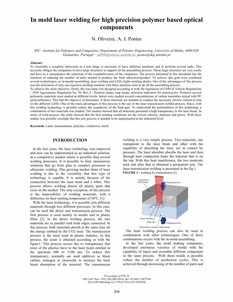
In the last years, the laser technology was improved and now can be implemented as an industrial solution, in a competitive market where is possible find several welding processes. It is possible to find, innumerous solutions that go from glue to complex processes as ultrasonic welding. This growing market share of laser welding is due to the versatility that this type of technology is capable. It is mainly because of the connection between the laser head and a robot. This process allows welding almost all plastic parts that exist on the market. The only exception, of this process is the impossibility of welding materials, with a difference on their melting temperature of 50ºC. [1] With the laser technology, it is possible join different materials through two different processes. In this case, can be used the direct and transmission process. The first process is used mainly in metals and in plastic films [2]. In the direct welding process, the two materials are in parallel with both edges connected. In this process, both materials absorb at the same time all the energy emitted by the CO2 laser. The transmission process is the most used in plastic industry. In this process, the seam is obtained according to with the figure1. This process occurs due to transparency that most of the plastics have to the laser beam emitted in the spectrum 600 to 1180 nm. To reduce this transparency, normally are used additives as black carbon, lumogen or clearweld, to increase the laser beam absorption of the material. The transmission
welding is a very simple process. Two materials, one transparent to the laser beam and other with the capability of absorbing the laser, are in contact by pressure. The laser absorber absorbs the laser and then through heat conduction heats the material that is on the top. With this heat transference, the two materials melt and after that is obtained a permanent join. The laser transmission welding is presented in the fig.1. FIGURE 1 - welding by transmission [1]
The laser welding process can also be used in combination with other technologies. One of these combinations occurs with the in-mold assembling. In the last years, the mold making companies, developed enormous varieties of molds with the capability of inject and assemble different component in the same process. With these molds is possible reduce the number of production cycles. This is achieved through decreasing of the number of parts and
Proceedings of PPS-29AIP Conf. Proc. 1593, 204-208 (2014); doi: 10.1063/1.4873764
2014 AIP Publishing LLC 978-0-7354-1227-9/$30.00
204
the post injection operations. In the market is a possible to find molds with multiple partition lines or rotary plates with the capability of changing their configuration during the injection process. Another common process is the use of robots or similar solutions, to exchange the different parts between the cavities or injection machines [3]. The In-mold assembly assures an exact alignment of the different components in the final product. This technique also reduces the total time of production and assembling [3]. The work presented in this document had the objective of study the combination of two different technologies, the in-mold assembling and laser transmission process. To validate this new process was used a case study. Following will be presented and discuss the different tasks made to validate the process.
RESULTS AND DISCUSSION
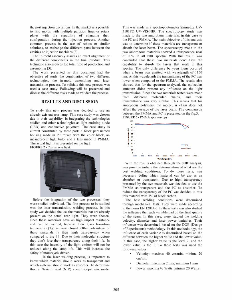
To study this new process was decided to use an already existent rear lamp. This case study was chosen due to their capability, in integrating the technologies studied and other technologies as light-emitting diode (LED) and conductive polymers. The case study is current constituted by three parts a black part named housing made in PC mixed with the color black, an incandescent light bulb, and a lens made in PMMA. The actual light it is presented on the fig.2 FIGURE 2 - Current rear light.
Before the integration of the two processes, they were studied individual. The first process to be studied was the laser transmission, welding process. In this study was decided the use the materials that are already present on the actual rear light. They were chosen, since these materials have an high impact resistance and can be welded, because their glass transition temperature (Tg) is very closed. Other advantage of these materials is their high transparency when compared to the PP. Due to their molecular structure they don’t lose their transparency along their life. In this case the intensity of the light emitter will not be reduced along the lamp life. This will increase the safety of motorcycle driver.
In the laser welding process, is important to know which material should work as transparent and which material should work as absorber. To determine this, a Near-infrared (NIR) spectroscopy was made.
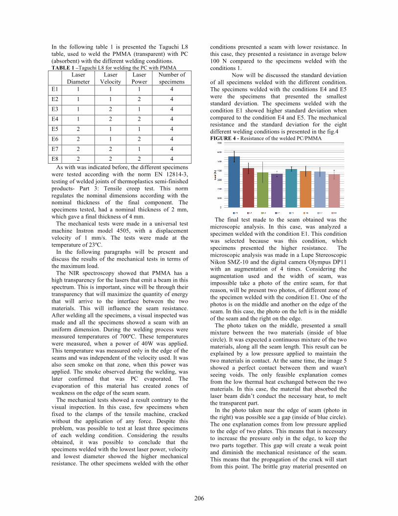
This was made in a spectrophotometer Shimadzu UV-3101PC UV-VIS-NIR. The spectroscopy study was made to the two amorphous materials, in this case to the PC and PMMA. The main objective of this analysis was to determine if these materials are transparent or absorb the laser beam. The spectroscopy made to the two amorphous materials showed a transparence near of 90% in all NIR spectra. With this result, was concluded that these two materials don't have the capability to absorb the lasers that work in this spectra. The only difference between them occurred when a beam was emitted with wavelength of 1150 nm. At this wavelength the transmittance of the PC was lower when compared to the PMMA. The results also showed that for the spectrum analyzed, the molecular structure didn't present any influence on the light transmission. Since the two materials tested were made from different molecular chains, and their transmittance was very similar. This means that for amorphous polymers, the molecular chain does not affect the passage of the laser beam. The comparison between the PMMA and PC is presented on the fig.3. FIGURE 3 - PMMA spectroscopy
With the results obtained through the NIR analysis, was possible initiate the determination of what are the best welding conditions. To do these tests, was necessary define which material can be use as an absorber or transparent. Due to high transparency presented by the two materials was decided to use the PMMA as transparent and the PC as absorber. To reduce the transparency of the PC was decided to mix this material with 3% of black carbon. The best welding conditions were determined through mechanical tests. They were made according to the norm EN 12814-3. In these tests was also studied the influence that each variable had on the final quality of the seam. In this case, were studied the welding velocity, diameter and laser power variables. Their influence was determined based on the DOE (Design of Experiments) methodology. In this methodology, the influence of each variable is determined based on the different between the higher value and the lower value. In this case, the higher value is the level 2, and the lower value is the 1. To these tests was used the following values;
• Velocity: maxima: 40 cm/min, minima 20 cm/min
• Diameter: maximun 2 mm, minimun 1 mm • Power: maxima 40 Watts, mínima 20 Watts
205
In the following table 1 is presented the Taguchi L8 table, used to weld the PMMA (transparent) with PC (absorbent) with the different welding conditions. TABLE 1 –Taguchi L8 for welding the PC with PMMA
Laser Diameter
Laser Velocity
Laser Power
Number of specimens
E1 1 1 1 4
E2 1 1 2 4
E3 1 2 1 4 E4 1 2 2 4
E5 2 1 1 4
E6 2 1 2 4
E7 2 2 1 4 E8 2 2 2 4 As with was indicated before, the different specimens were tested according with the norm EN 12814-3, testing of welded joints of thermoplastics semi-finished products- Part 3: Tensile creep test. This norm regulates the nominal dimensions according with the nominal thickness of the final component. The specimens tested, had a nominal thickness of 2 mm, which gave a final thickness of 4 mm. The mechanical tests were made in a universal test machine Instron model 4505, with a displacement velocity of 1 mm/s. The tests were made at the temperature of 23ºC. In the following paragraphs will be present and discuss the results of the mechanical tests in terms of the maximum load. The NIR spectroscopy showed that PMMA has a high transparency for the lasers that emit a beam in this spectrum. This is important, since will be through their transparency that will maximize the quantity of energy that will arrive to the interface between the two materials. This will influence the seam resistance. After welding all the specimens, a visual inspected was made and all the specimens showed a seam with an uniform dimension. During the welding process were measured temperatures of 700ºC. These temperatures were measured, when a power of 40W was applied. This temperature was measured only in the edge of the seams and was independent of the velocity used. It was also seen smoke on that zone, when this power was applied. The smoke observed during the welding, was later confirmed that was PC evaporated. The evaporation of this material has created zones of weakness on the edge of the seam seam. The mechanical tests showed a result contrary to the visual inspection. In this case, few specimens when fixed to the clamps of the tensile machine, cracked without the application of any force. Despite this problem, was possible to test at least three specimens of each welding condition. Considering the results obtained, it was possible to conclude that the specimens welded with the lowest laser power, velocity and lowest diameter showed the higher mechanical resistance. The other specimens welded with the other
conditions presented a seam with lower resistance. In this case, they presented a resistance in average below 100 N compared to the specimens welded with the conditions 1.
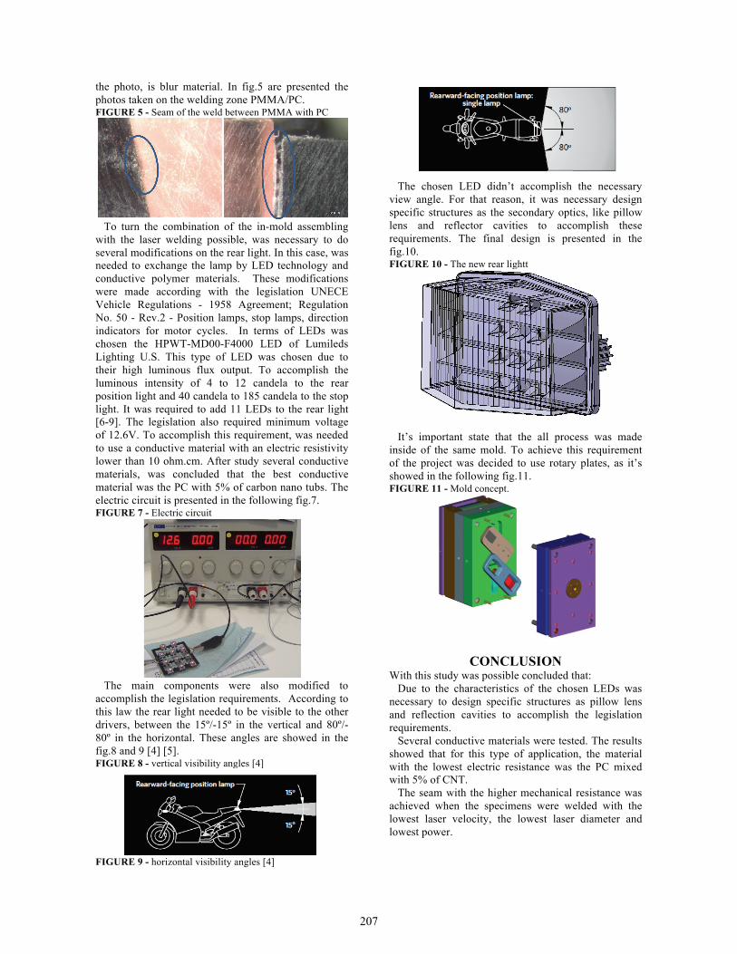
Now will be discussed the standard deviation of all specimens welded with the different condition. The specimens welded with the conditions E4 and E5 were the specimens that presented the smallest standard deviation. The specimens welded with the condition E1 showed higher standard deviation when compared to the condition E4 and E5. The mechanical resistance and the standard deviation for the eight different welding conditions is presented in the fig.4 FIGURE 4 - Resistance of the welded PC/PMMA
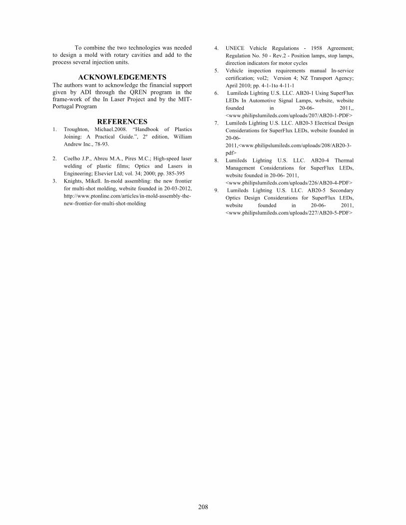
The final test made to the seam obtained was the microscopic analysis. In this case, was analyzed a specimen welded with the condition E1. This condition was selected because was this condition, which specimens presented the higher resistance. The microscopic analysis was made in a Lupe Stereoscopic Nikon SMZ-10 and the digital camera Olympus DP11 with an augmentation of 4 times. Considering the augmentation used and the width of seam, was impossible take a photo of the entire seam, for that reason, will be present two photos, of different zone of the specimen welded with the condition E1. One of the photos is on the middle and another on the edge of the seam. In this case, the photo on the left is in the middle of the seam and the right on the edge. The photo taken on the middle, presented a small mixture between the two materials (inside of blue circle). It was expected a continuous mixture of the two materials, along all the seam length. This result can be explained by a low pressure applied to maintain the two materials in contact. At the same time, the image 5 showed a perfect contact between them and wasn't seeing voids. The only feasible explanation comes from the low thermal heat exchanged between the two materials. In this case, the material that absorbed the laser beam didn’t conduct the necessary heat, to melt the transparent part. In the photo taken near the edge of seam (photo in the right) was possible see a gap (inside of blue circle). The one explanation comes from low pressure applied to the edge of two plates. This means that is necessary to increase the pressure only in the edge, to keep the two parts together. This gap will create a weak point and diminish the mechanical resistance of the seam. This means that the propagation of the crack will start from this point. The brittle gray material presented on
206
the photo, is blur material. In fig.5 are presented the photos taken on the welding zone PMMA/PC. FIGURE 5 - Seam of the weld between PMMA with PC
To turn the combination of the in-mold assembling with the laser welding possible, was necessary to do several modifications on the rear light. In this case, was needed to exchange the lamp by LED technology and conductive polymer materials. These modifications were made according with the legislation UNECE Vehicle Regulations - 1958 Agreement; Regulation No. 50 - Rev.2 - Position lamps, stop lamps, direction indicators for motor cycles. In terms of LEDs was chosen the HPWT-MD00-F4000 LED of Lumileds Lighting U.S. This type of LED was chosen due to their high luminous flux output. To accomplish the luminous intensity of 4 to 12 candela to the rear position light and 40 candela to 185 candela to the stop light. It was required to add 11 LEDs to the rear light [6-9]. The legislation also required minimum voltage of 12.6V. To accomplish this requirement, was needed to use a conductive material with an electric resistivity lower than 10 ohm.cm. After study several conductive materials, was concluded that the best conductive material was the PC with 5% of carbon nano tubs. The electric circuit is presented in the following fig.7. FIGURE 7 - Electric circuit
The main components were also modified to accomplish the legislation requirements. According to this law the rear light needed to be visible to the other drivers, between the 15º/-15º in the vertical and 80º/-80º in the horizontal. These angles are showed in the fig.8 and 9 [4] [5]. FIGURE 8 - vertical visibility angles [4]
FIGURE 9 - horizontal visibility angles [4]
The chosen LED didn’t accomplish the necessary view angle. For that reason, it was necessary design specific structures as the secondary optics, like pillow lens and reflector cavities to accomplish these requirements. The final design is presented in the fig.10. FIGURE 10 - The new rear lightt
It’s important state that the all process was made inside of the same mold. To achieve this requirement of the project was decided to use rotary plates, as it’s showed in the following fig.11. FIGURE 11 - Mold concept.
CONCLUSION With this study was possible concluded that: Due to the characteristics of the chosen LEDs was necessary to design specific structures as pillow lens and reflection cavities to accomplish the legislation requirements. Several conductive materials were tested. The results showed that for this type of application, the material with the lowest electric resistance was the PC mixed with 5% of CNT. The seam with the higher mechanical resistance was achieved when the specimens were welded with the lowest laser velocity, the lowest laser diameter and lowest power.
207
To combine the two technologies was needed to design a mold with rotary cavities and add to the process several injection units.
ACKNOWLEDGEMENTS The authors want to acknowledge the financial support given by ADI through the QREN program in the frame-work of the In Laser Project and by the MIT-Portugal Program
REFERENCES 1. Troughton, Michael.2008. “Handbook of Plastics
Joining: A Practical Guide.”, 2º edition, WilliamAndrew Inc., 78-93.
2. Coelho J.P., Abreu M.A., Pires M.C.; High-speed laserwelding of plastic films; Optics and Lasers inEngineering; Elsevier Ltd; vol. 34; 2000; pp. 385-395
3. Knights, Mikell. In-mold assembling: the new frontierfor multi-shot molding, website founded in 20-03-2012,http://www.ptonline.com/articles/in-mold-assembly-the-new-frontier-for-multi-shot-molding
4. UNECE Vehicle Regulations - 1958 Agreement;Regulation No. 50 - Rev.2 - Position lamps, stop lamps,direction indicators for motor cycles
5. Vehicle inspection requirements manual In-servicecertification; vol2; Version 4; NZ Transport Agency;April 2010; pp. 4-1-1to 4-11-1
6. Lumileds Lighting U.S. LLC. AB20-1 Using SuperFluxLEDs In Automotive Signal Lamps, website, websitefounded in 20-06- 2011,,<www.philipslumileds.com/uploads/207/AB20-1-PDF>
7. Lumileds Lighting U.S. LLC. AB20-3 Electrical DesignConsiderations for SuperFlux LEDs, website founded in20-06-2011,<www.philipslumileds.com/uploads/208/AB20-3-pdf>
8. Lumileds Lighting U.S. LLC. AB20-4 ThermalManagement Considerations for SuperFlux LEDs,website founded in 20-06- 2011,<www.philipslumileds.com/uploads/226/AB20-4-PDF>
9. Lumileds Lighting U.S. LLC. AB20-5 SecondaryOptics Design Considerations for SuperFlux LEDs,website founded in 20-06- 2011, <www.philipslumileds.com/uploads/227/AB20-5-PDF>
208