Embed Size (px)
Citation preview

fflsmm pp! _ iiilliiflÏ'
|uBM KM EUR 2649e ■íkiívÍÍ.'
r '■
MB" anwmå'M^
1953^ llfiip« ílWíSièiuiS^lí
EUROPEAN ATOMIC ENERGY COMMUNITY - EURATOM
h duv vi&m'åSSSc i·;
EN-PILE APPLICATION OF STRAIN GAUGES
PRELIMINARY RESULTS
«así̂ vii ite'- ·;:,· H ^ 3 # S H rt ™ ■· ■ < r ·?» ■■■'■
P. WELTEVREDEN « iPIHi l
Ä ^ e i S P l ^ e P ^ I 9 6 6
ÉieËliSiSi'iSIlMii mmsÊàmm 0RGEL Pr09ram
llliSMilèil oint Nuclear Research Center
Ispra Establishment - Italy
pire ngineering Department
Technology Service
an ίΙΪΙκΙίΡΙ

Ili «fiPîSaïîS^K'1 ̂ f̂5™
' fsiaWi*!; íSSâ'!;-i.'Sff'*!;* ;lât-ft
^ f » lililí Milffi
I S i PSBÉ^P ir*';
This document was prepared under the sponsorship of the Commission of the European Atomic Energy Community (EURATOM).
mi Neither the EURATOM Commission, its contractors nor any person acting on their behalf:
Make any warranty or representation, express or implied, with respect to the accuracy, completeness, or usefulness of the information contained in this document, or that the use of any information, apparatus, method, or process disclosed in this document may not
'Jtif.· infringe privately owned rights; or
Assume any liability with respect to the use of, or for damages resulting from the use of any information, apparatus, method or process disclosed in this document.
ft 11 n.îî.a 'Pli'ü:*:'ί "·Ί»ί3ΐ
This report is on sale at the addresses listed on cover page 4
FB 40 DM 3,20 Lit. 500 Fl. 3,—
When order ing, please quote the EUR n u m b e r and the title, :.1„
which are indicated on the
Printed by Snoeck-Ducaju

EUR 2649.Θ
IN-PILE APPLICATION OF STRAIN GAUGES - PRELIMINARY RESULTS by P. WELTEVREDEN
European Atomic Energy Community - EURATOM ORGEL Program Joint Nuclear Research Center - Ispra Establishment (Italy) Engineering Department - Technology Service Brussels, April 1966 - 26 Pages - 12 Figures - FB 40
This paper contains a description of the realisation of the first stage of an irradiation program on resistance strain gauges. The scope of this program is to establish limits on the use of resistance strain gauges in a radioactive environment. To this extend a number of strain gauges is attached to a tube-section in various compensating arrangements. The tube section is mounted inside an irradiation rig and subsequently introduced in a reflector
EUR 2649.e
IN-PILE APPLICATION OF STRAIN GAUGES - PRELIMINARY RESULTS by P. WELTEVREDEN
European Atomic Energy Community - EURATOM ORGEL Program Joint Nuclear Research Center - Ispra Establishment (Italy) Engineering Department - Technology Service Brussels, April 1966 - 26 Pages - 12 Figures - FB 40
This paper contains a description of the realisation of the first stage of an irradiation program on resistance strain gauges. The scope of this program is to establish limits on the use of resistance strain gauges in a radioactive environment. To this extend a number of strain gauges is attached to a tube-section in various compensating arrangements. The tube section is mounted inside an irradiation rig and subsequently introduced in a reflector

position of a CP-5 type reactor. The report gives a detailed description of the irradiation device and summarises the data in the form of strain gauge parameters versus integrated neutron flux. Definite conclusions concerning irradiation stability are given and the continuation of the irradiation program is outlined.
position of a CP-5 type reactor. The report gives a detailed description of the irradiation device and summarises the data in the form of strain gauge parameters versus integrated neutron flux. Definite conclusions concerning irradiation stability are given and the continuation of the irradiation program is outlined.

EUR 2649e
EUROPEAN ATOMIC ENERGY COMMUNITY - EURATOM
IN-PILE APPLICATION OF STRAIN GAUGES PRELIMINARY RESULTS
by
P. WELTEVREDEN
1966
ORGEL Program
Joint Nuclear Research Center Ispra Establishment - Italy
Engineering Department Technology Service

CONTENTS
1. INTRODUCTION 3
2. IRRADIATION FACILITY 4
3. IRRADIATION RIG 4
3.1. In-Pile Section 4
3.2. Out-of-Pile Section 5
3.3. Handling . 6
4. SAFETY CONSIDERATIONS 7
4.1. Temperature distribution 7
4.2. Structural analysis 7
4.3. Reactivity effects 7
4.4. Estimation of activity 8
5. MEASUREMENTS 8
5.1. Selection and out-of-pile calibration 8
5.2. In-pile measurements 10
6. RESULTS 12
7. CONCLUSIONS 16
8. FUTURE EXPERIMENTS 16
9. ACKNOWLEDGEMENT 17
10. REFERENCES 17
SUMMARY
This paper contains a description of the realisation of the first stage of an irradiation program on resistance struin gauges. The scope of this program is to establish limits on the use of resistance strain gauges in a radioactive environment. To this extend a number of strain gauges is attached to a tube-section in various compensating arrangements. The tube section is mounted inside an irradiation rig and subsequently introduced in a reflector position of a CP-5 type reactor. The report gives a detailed description of the irradiation device and summarises the data in the form of strain gauge parameters versus integrated neutron flux. Definite conclusions concerning irradiation stability are given and the continuation of the irradiation program is outlined.
In-pile Application of Strain Gauges Preliminary Results H
1. INTRODUCTION
For many problems in the field of experimental stress analysis the application of resistance strain gauges is indispensable. Among others, it is the only technique whicb can be applied successfully for strain measurements at high temperatures. Its limitation lies basically in the fact that besides strain, there is a large number of parameters whicb might effect the resistance of the strain gauge. In many cases such parasitic effects can render a strain gauge measuring point useless. This will occur either when the magnitude of such effects is of the same order as the strain signal to be measured and/or when sucb effects do not show sufficient reproducibility. Some of these effects can be compensated for by choosing suitable bridge arrangements. In practice, however, it turns out that even apart from material inhomogenities, the technique of strain gauge mounting does not allow complete matching of active and dummy gauges. The most obvious source of parasitic effects is of course the temperature. Specific resistance variations, differentiel expansions, metallurgical changes, etc., are all due to temperature variations and introduce parasitic (or so-called "apparent") strain signals. Another source of parasitic effects is the medium in which strain measurements are to be performed. Corrosion, isolation resistance variations, and other phenomena are to a large extent determined by the surrounding medium. When performing static strain measurements the time comes in as a very important parameter. Actually, when considering mechanical strain variations of short duration (dynamic phenomena) all the above mentioned effects of temperature and medium play a minor rôle as long as the velocity of the mechanical phenomena is large compared to that of heat and mass-transfer phenomena. In the case of static measurements, however, all the above mentioned effects have to be taken into account, in addition posing problems of creep of strain gauge components.
When in-pile strain measurements have to be performed one has to take into account also the apparent strain signals due to radiation damage. Due to the statistic nature of the irradiation damage one can expect that also under such circumstances the normal compensation systems might be a way out. Nevertheless, it will be necessary to establish the amount of parasitic effects introduced by radiation damage and to study the lifetime of the various strain gauge components. These items formed the subject of the research of which preliminary results are presented in this paper.
The first sections of the paper are concerned with a detailed description of the irradiation device and related items. It was considered useful to include such a description as the main burden of an irradiation program lies always in the preparation of the experimental set-up. The effort of all the people engaged in this irradiation program is in our opinion best illustrated by a detailed description of its preparation.
The second part of the paper presents the results obtained in this first stage of the program.
(*) Manuscript received on November 15, 1965.
3
2. IRRADIATION FACILITY
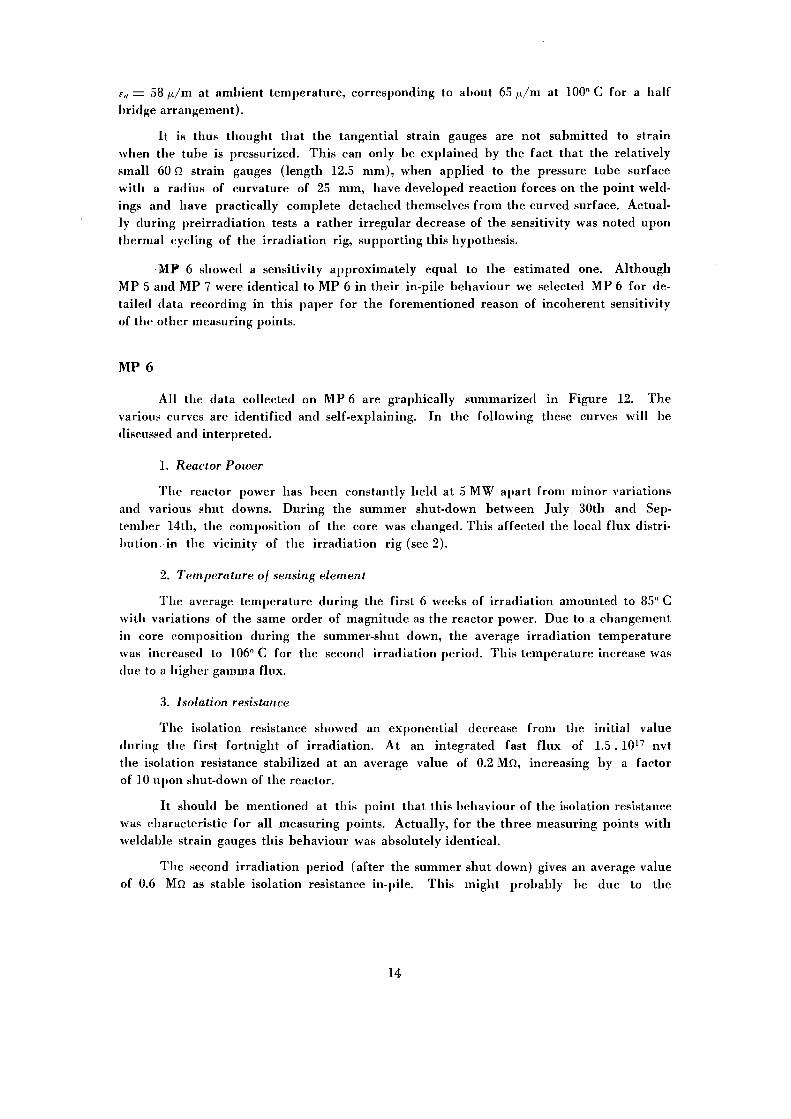
Primarily for reasons of convenience it was decided to perform the first irradiation experiment in the Ispra-I reactor at the Euratom center at Ispra. The Ispra-I reactor is a low-power, heavy water cooled and moderated reactor of the CP-5 type. When the irradiation program was to be started, a vertical irradiation position was available in the heavy water tank, just inside the vessel wall. At this position, a relatively strong thermal neutron and gamma flux was available, the fast neutron flux being rather weak.
The position of tbe irradiation rig is indicated on Fig. 1 and is in effect the position of a peripherical fuel element. Fig. 2 gives a thermal flux map obtained in this position. This flux map was compared to data obtained in the CP-5 reactor at Argonne and reasonable agreement was found [ref. 1]. As a reference value for the average thermal neutron flux at the irradiation position a value of 3.1013 n/cm2 sec was selected, corresponding to an integrated thermal flux of 7.5.1019 nvt for an irradiation period of one month.
As no data on fast flux were available at the irradiation position, a reference value for the fast neutron flux was selected by approximate conversion of the data of reference 1. A fast neutron flux value of 1011 n/cm2 sec was selected, corresponding to 2.5.1017 nvt after one month irradiation.
During the irradiation experiment the reactor was continuously operated at a power level of 5 MW, interrupted only for short time shut-down periods for reasons of inspection and tbe annual shut-down period during August 1964 which was extended to almost two months for reasons of installation of a complicated in-pile experiment.
3. IRRADIATION RIG
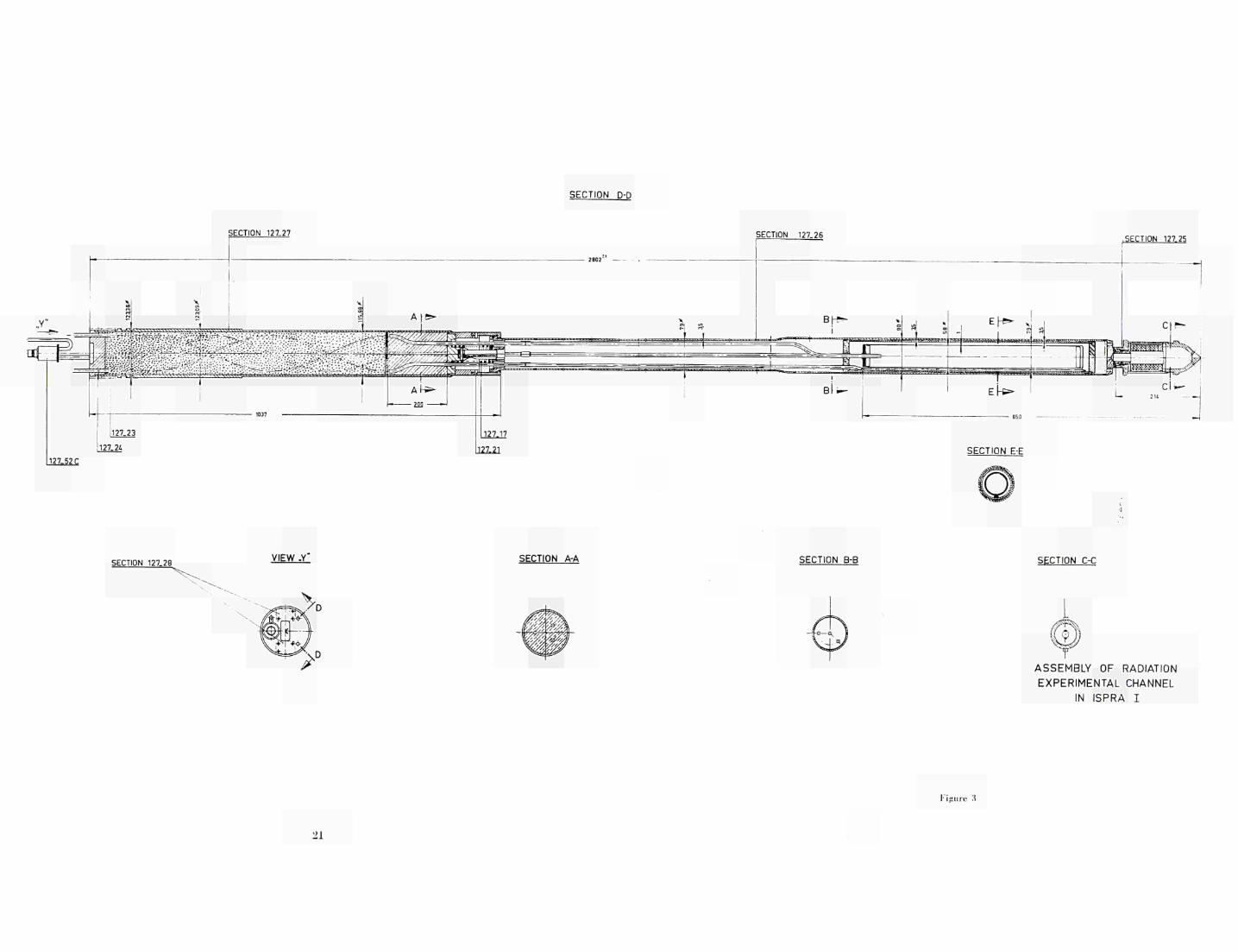
3.1 . Pile-section
The irradiation rig is loaded through a hole in the top shield of the reactor vessel. The upper part of the rig fills exactly this hole once the rig is in position, and is hence called the "shield-plug". This plug has the following functions:
a) radiation shield b) helium tight sealing c) passage of gas lines and instrument cables d) support of the rig.
These functions are realised in the design as presented in the attached drawing (Fig. 3). An accurately machined tube is filled with shielding material after three spiral-ed mini-tubes have been mounted at the inside. The lower section of the plug is filled with lead for effective gamma shielding. The plug is subsequently filled with concrete for additional neutron shielding. Although the main support of the rig is given by the shield plug, the lower end of the rig is seated on a nozzle in the bottom grid plate of the reactor vessel. This nozzle serves primarily for positioning of the rig. During operation of the reactor the nozzle must be closed by the lower end of the rig, in order to
avoid reduction of the coolant flow in the fuel element region. A minimum seating force of the rig is thus required corresponding to the pressure difference over the nozzle. Such a seating force (including a safety factor of 2) is realised by means of a calibrated spring between the shield plug and the in-pile part of the rig. This solution was possible as the required seating force is small compared to the weight of the shield plug. The transition piece between shield plug and in-pile part of the rig is moreover designed in such a way that a misalignement of 5° between these parts can be absorbed easily. This feature was necessary for reasons of differential thermal expansion.
Tbe in-pile section of the rig contains a tube section to which the strain gauges are applied on the outer surface. The inner volume of this tube section is connected to an out-of-pile pressurising system through a gas tight minitube. In this way it is possible to subject the strain gauges during irradiation to a certain amount of strain, determined by the static pressure, the dimensions of the tube and the modulus of elasticity of the tube material.
For reasons of security, this tube section is mounted inside a gas tight containment tube, whicb in turn is connected to a shroud tube taking care of the structural integrity of the rig.
The sensing element and its surrounding safety tube are free to expand axially, both with respect to each other and to the shroud tube. They are connected directly to the shield plug through three minitubes. One of these minitubes is the pressurising line for the sensing element. The other two are connected to an out-of-pile circuit which sets up a gas circulation in the annular space between sensing element and safety tube, enabling to control the atmosphere of the strain gauges. One of the latter two minitubes contains the leading wires.
At the lower end of the shroud tube a cylindrical container is mounted. In Fig. 3 the construction is shown. The hermetically sealed container is filled with a number of gaskets and packings. As the space required for the strain gauge irradiation was more than sufficient it was decided to combine the irradiation experiments on the gauges with a passive irradiation of these sealings. The purpose of the irradiation of the gaskets and packings is to study their deformation characteristics after exposure to a certain integrated flux. A screwed connection is realised between the container and the rest of the rig in order to allow the mounting of a second strain gauge rig when the measurements show that increasing the integrated flux does not give additional information on the behaviour of the gauges. The screwed connection is reinforced by means of a helicoil for increased reliability during remote handling.
3.2. Out-of-pile section
On the top of the shield plug the following connections are made:
1. Between the out-of-pile pressurising system and the in-pile sensing element. 2. Between the out-of-pile measuring equipment and the strain gauges and thermo
couple which are attached to the sensing element. 3. Between out-of-pile helium circuit and the inlet and outlet of the'in-pile helium
circuit between sensing element and safety tube.
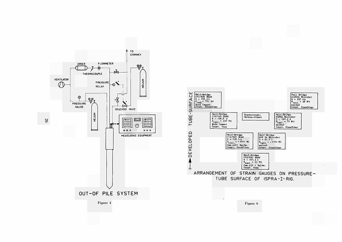
An overall view of the out-of-pile system is given in Fig. 4.
ad 1. The main components are a pressurized helium container and a pressure regulating system with safety valve.
ad 2. The electrical connections between rig and out-of-pile measuring equipment are realized by means of a leaktight multi-contact miniature connector of the bayonet lock type. Special precautions have been taken with respect to the mounting of this connector as the soldered connections of the individual wires and pins are very fragile.
The strain gauge and thermocouple signals are transmitted to automatic recording systems. For strain gauges: a channel selector, a measuring bridge and a paper recorder. For thermocouples: a measuring bridge with direct recorder.
ad 3. The out-of-pile helium circuit contains: a) a helium compressor of the oil controlled membrane type, with a continuously
variable flow, 1)) a static pressure regulating system, made up by a pressurized helium container,
reducing valve, a pressure regulator and safety valve, c) temperature and pressure recorders for in-and outlet of the rig, d) a flow-meter, e) a helium dryer, f) contact manometer for emergency purposes.
3.3. Handiin«;
The loading of the experimental rig will principally be performed as the loading of a fuel element. No special precautions have to be taken when the rig is mounted for the first time.
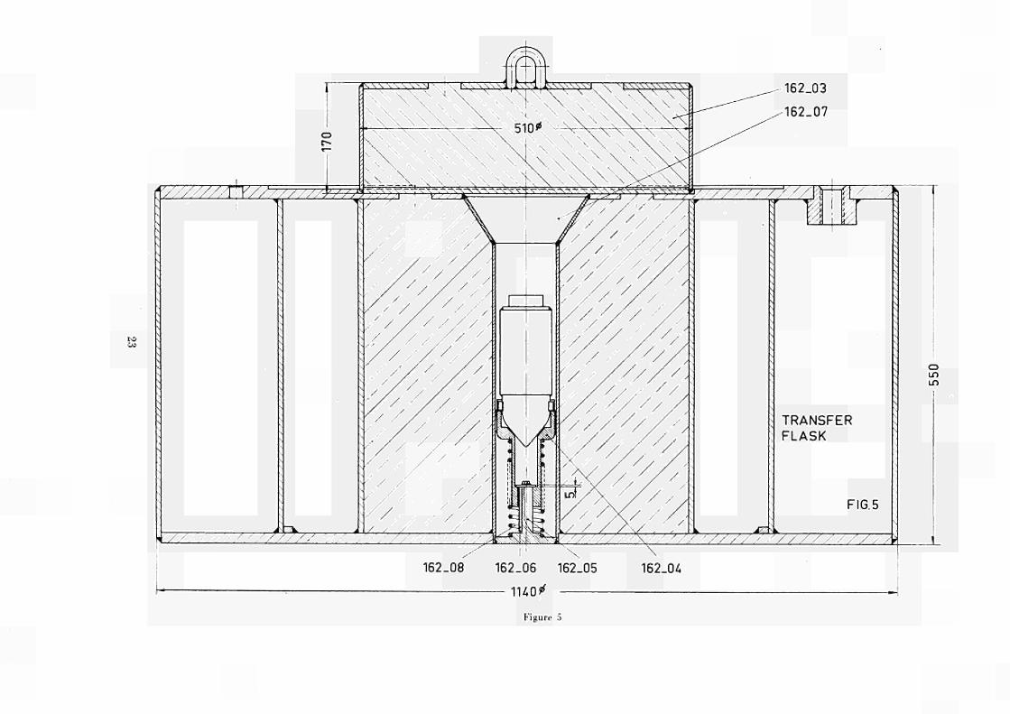
However, unloading requires special equipment and handling as the lower part of the rig, containing the capsule with gaskets and packings, has to be disconnected from the first rig and in the same handling cycle be connected to the second. For this purpose a special transfer flask for the gaskets-capsule has been constructed (Fig. 5). This flask is used in the following way.
The first step is to withdraw the channel from the reactor vessel and hoist it into the fuel-element transfer flask (available in the reactor hall).
Next, this flask, containing the entire rig, will be placed on top of the gasket-capsule transfer flask. By means of a special designed tool, the rig will then be lowered until the bottom of the rig is supported on a locking system in the capsule transfer flask. By turning the rig the gasket capsule will be disconnected from the upper part of the rig. Next, this upper part of the rig is hoisted into the fuel-element transfer flask and is then ready for transportation to the gamma-cooling-pool. The fuel element transfer flask is thereafter reloaded with a new rig assembly. Connection of the capsule to this assembly is performed inversely identical to the disconnection sequence. Ultimately the new complete rig assembly is mounted in the reactor vessel.
The various operations as described above are tested for safe handling in two stages. First the handling sequence has been performed on a dummy channel out of pile in the laboratories of the Technology Department. For this purpose a special rig was constructed, which has the same dimensions and properties as the fuel element transfer flask as far as handling is concerned. Of these operations a movie picture has been made. Next, an ultimate handling test has been performed in the reactor hall of Ispra.

4. SAFETY CONSIDERATIONS
4.1. Temperature Distribution
The temperature distribution in the assembly has been calculated for the following cross sections:
1. over the three tubes, 2. over the packing capsule.
In both cases the maximum temperatures are based on a D 2 0 temperature of 50° C, being the exit temperature of the D 20, and a heat production of 1 Watt/gram material. Although the helium, circulating through the annular space between safety and pressure tube, can be cooled outside the reactor, only the heat transport by conduction of the helium to the D 2 0 has been considered from a point of view of safety. For this case, the maximum temperature in the wall of the pressure tube is calculated to be about 120" C. With respect to the temperature distribution in the packings and capsule wall, an equal heat flux has been considered at the inside surface of the packings and at the outside surface of the capsule. For this assumption one arrives to a maximum temperature in the packings of about 132° C.
During the experiments, the temperature of the pressure tube is measured by means of a thermocouple. Although the helium circulating through the annular space of the pressure and safety tubes, serves primarily to present ionization effects in connection with the strain gage measurements, it is possible to change the helium flow rate in order to regulate the maximum temperature in the pressure tube. During irradiation the actually measured value of the pressure tube temperature amounted to 105° C (with no helium circulation) at 5 MW reactor power.
4.2. Structural Analysis
The operating pressure in the pressure, resp. safety tube are respectively maximum 8 atm and about 1,2 atm.
The tubes are designed for a maximum pressure of respectively 10 and 30 atm. For the latter a safety factor of 3 has been included with regard to shock wave loading of the safety tube, by bursting of the pressure tube.
For these pressures, the maximum membrane stresses turn out to be : pressure tube 2.3 kg/mm2 (10 atm, 120° C) safety tube 3.6 kg/mm2 (30 atm, 120° C)
As Heddenal 1530 tubes were selected with a yield strength of 22 kg/mm2 at 120° C, being the maximum expected temperature, the permissible stress for static loading is 2/3 X 22 = 14,7 kg/mm2 .
4 .3 . Reactivity Effects
The experimental facility is introduced into the reactor at position 4. An estimation has been made concerning the reactivity change caused by this introduction, based

on "Preliminary Report on Reactivity Effects and Neutron Flux Distribution in the Experimental Channels of the Ispra I Reactor" by the CNEN.
This report presents the results of reactivity change experiments, performed by introducing P.V.C, into the reactor core at position 8. Although position 8 is situated at the same radius in the reactor core as position 4, these values are not completely representative for the calculation of the reactivity change in our case, due to unsymmetric core geometry. Nevertheless, we have to accept this as a base for our estimation, since there are no other experimental data available.
From the data given in the above mentioned report, it has been calculated that introduction of the experimental channel will cause a reactivity change of about 480 pcm. The reactivity change during operation, due to accidental in-leaking of D 2 0 in the annular space between safety tube and sensing element of the assembly, has been estimated in the same way and amounts to -\- 55 pcm.
4.4. Estimation of activity
The experimental facility will be exposed to an average thermal flux of 3.103 neutrons/cm2 sec. An estimation has been made concerning the induced activity of the upper part of the assembly and of the capsule with the gaskets and packings, for an irradiation time of maximum 1 year.
The estimation of the activity for the upper part is performed by a method given in "Rapid Assessment of Neutron Activation" by Russel B. Mesler, and amounts to 7000 r/hr at a distance of 1 meter in air.
For the gaskets and packings an activity of 1680 r /hr is estimated based on the results of preliminary irradiation test performed on the same gaskets and packings in the Ispra I reactor by the department of nuclear chemistry.
As described before, a special transfer flask for the gasket-capsule has been constructed. The thickness of the lead flask amounts to 20 cm and reduces the radiation intensity at the outer surface of the lead flask to 2 mr/hr.
5. MEASUREMENTS
5.1. Selection and out-of-pile calibration
Making the selection of the strain gauges to be studied, two rules were followed, i.e.:
a) Organic materials should be avoided as much as possible as these are generally very sensitive to radiation damage.
b) The same rules for temperature compensation are valid for compensation of radiation effects.
Item a) limits our choice to the so-called high-temperature strain gauges only, as all other types of gauges have an organic support (paper or epoxy-resin). Only high-temperature gauges are applied without support by means of a ceramic cement. Concern-
8

ing the leading wires, the only wires to be considered are those with a glass-fiber or a ceramic insulation.
Item b) indicates that one should operate the active strain gauge with a so-called "hot" dummy gauge, in order to cancel out as much as possible the parasitic radiation effects. This can be realised in two ways, i.e. by constructing a half-bridge or a full bridge arrangement of the strain gauges. The first solution has the advantage that only two strain gauges are necessary for one measuring point. However, as the leading wires of the strain gauges form part of the bridge circuit, eventual radiation damage to these wires influences the balance of the bridge, developing apparent strain signals. A full bridge arrangement excludes completely the effects of radiation damage to the leading wires as these form only part of respectively supply and measuring circuit of the bridge.
The above mentioned considerations led to the selection of a number of high temperature strain gauges, all of them being operated in half or full-bridge arrangements with active dummy gauges.
The distribution of these arrangements over the sensing element henceforth called measuring points is given on Fig. 6. Each measuring point on this figure is identified by a description indicating resp.: type of strain gauge, resistance of active and dummy gauge, isolation resistance, type of leading wire and bridge arrangement.
Due to space limitations for the leading wires a maximum number of 7 measuring points could be applied to the sensing element. In determining the position of these measuring points a distance of 50 mm from the end-closures of the tube was taken into account in order to be sure to have a membrane state of stress at all the measuring points. The dimensions of the sensing tube being 0 58/56 the e-f olding length of the discontinuity stresses due to the end closures is:
I = 0.778 y/~77t = 4.15 mm.
Consequently, a decrease of
50 > 99.9 %
4.15 is obtained of the discontinuity stresses at that location. Picture No. 7 gives a close-up of the sensing-element, just before mounting of the safety tube.
During irradiation, the pressure in the sensing element was varied step-wise from zero to 8 atm gage pressure.
The membrane stresses in the sensing tube at the maximum pressure are:
ρ . r 0.08 . 28.5 at = = = 2.28 kg/mm2
ρ · r σ„ = = 1.14 kg/mm2
2t
Substituting these values in the equations for tangential and axial strain, one ob-
et = — - ν . — = 293 μ/τα lil tl
ta ins:
σα at e« - "g - ν . —
for E — 6500 kg/mm2 at ambient temperature.
58/t/m
ν = 0.33 (Ιμ,/m = 1 . IO-6 m/m == 1 μ inch/inch).
As for a half bridge arrangement with an active tangential strain gauge and an active axial dummy gauge the total unbalance of the bridge is determined by the difference between tangential and axial strain, the effective strain signal to be measured would amount to:
Eeff = et - F,, = 293 — 58 = 235 μ/m
This strain value should be found from the actual measurements when correction for leading wire resistance and actual gauge factor value has been made. It will be clear that the strain signal of a full-bridge arrangement should be twice as big compared to a half-bridge arrangement, i.e. 470 μ/τα.
In order to check the behaviour of the installed measuring points before submitting them to radiation, the completely assembled rig was mounted out of pile on a support containing a furnace for simulated gamma-heating (see picture No. 8). The photograph was taken during conditioning of the rig. To this extend the rig was flushed with preheated helium in order to evacuate the humid air, remained after assembling. When the isolation resistance of the measuring points reached a value of 500 ΜΩ the helium circulation was stopped and the circuit closed. At the expected in-pile temperature calibration measurements were performed. Not all the measuring points indioated the calculated strain values. This must be attributed to various factors as imperfect mounting, relatively weak bonding strengths between elements and Al-base material, temperature effects on welding strength etc. Nevertheless, apart measuring point 3 which gave no strain signal at all, all measuring points showed good reproducibility in their strain signal and gave satisfactory isolation resistance and circuit resistance.
5.2. In-pile measurements
The rig was mounted June 18th, 1964, and measurements started the next day.
During the first fortnight measurements were performed two times each day. Later this was reduced to once a day. As no data logger was available at that time, the measurements were performed manually and tahellized on tables. Fig. 9 gives an example of such a data sheet which is actually a reproduction of data sheet 4 of measuring point 6. From this data sheet it can be seen that the following parameters have been measured :
1. Reactor Power, 2. Temperature of sensing element, 3. Isolation resistance, 4. Gauge resistances, 5. Strain signal at 2.5, 5 and 8 atm gauge pressure, 6. Drift.
— Measurement of the reactor power served principally as a flux indication. As no flux wires were encapsulated in the first irradiation rig, the integrated flux had to be determined from continuous reactor power measurements.
— The temperature measurement of the sensing element gave an additional indication of the flux level. Actually it turned out that the temperature increase due to gamma
10
heat ing was very stable and reproducible . T h e main purpose of the t empera tu re measure
ment was, however, to correct for gauge resistance variat ions due to t empera tu re varia
tions and for correction of Young's modulus and gauge factor variat ions with tempera
ture.
— Measurement of isolation resistance and individual gauge resistance were per
formed in order to enable in terpre ta t ion of the total unstabi l i ty of the measuring points
in terms of variat ions of these parameters wi th integrated flux.
Concerning radia t ion induced resistance variat ions of the grids of the strain gauges
it will be clear tha t such resistance variat ions will give rise to apparen t strains as their
direct consequence.
Regarding variat ions in isolation resistance the situation is slightly more compli
cated. Considering the isolation resistance as a shuntresistance over the strain gauge grid
resistance, the following relation can easily be derived :
Ri (R2—R3)
K.R2(R1 + Ra)
in which :
F a i > p =z apparen t strain due to variat ion of isolation resistance from R2 to R s
Ri = resistance strain gauge (Ω)
R2 — init ial isolation resistance (Ω)
R-¿ = final isoltion resistance (Ω)
K = gauge factor of strain gauge.
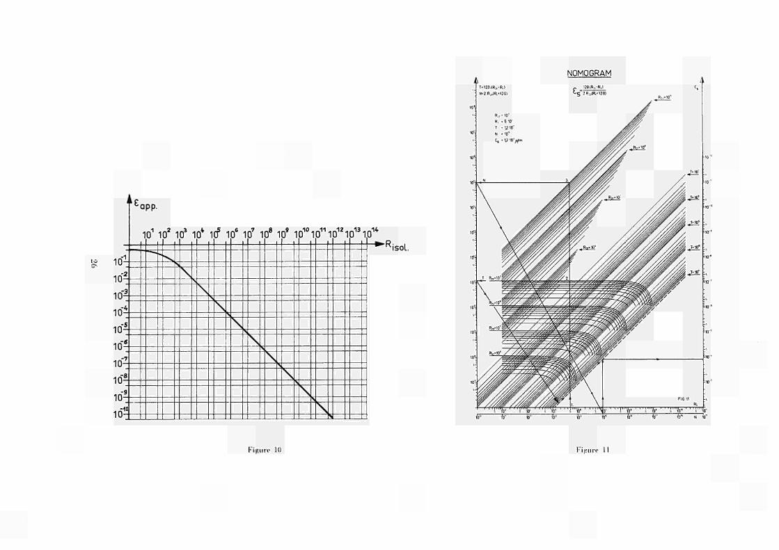
F igure 10 represents the appa ren t strain signal obtained as a result of a variation
of the isolation resistance from infinity to t h e values on the Ri80i-axis. F r o m this curve it
follows tha t variat ions of the isolation resistance between infinity and 10 8 Ω (100 Μ Ω ) result
in appa ren t s t ra in smaller t han 1.10"° (1/x/m) and can thus be considered of no importance.
A decrease of the isolation resistance from infinity to ΙΟ7 Ω (10 Μ Ω ) results in an apparent
signal of about 7.10"6 (7 μ/τα) which starts to affect the accuracy of the measurement .
Under normal circumstances an isolation resistance of about 100 ΜΩ is thus considered as
a m i n i m u m acceptable value and is easily obtained. One of the effects of i rradiat ion
damage, however is to reduce the value of the isolation resistance far below the treshold
value of 100 ΜΩ. In the next chapter this will be discussed in detail . For the moment it is
sufficient to know tha t saturat ion values of the isolation resistance inpile are of the
order of 0,5 ΜΩ. For i l lustrat ion purposes it follows from Fig. 10, tha t a decrease of the
isolation resistance from infinity to 0,5 ΜΩ results in an apparen t strain signal of 1,05.104
(105 μ/va). Consequently, the magni tude of apparen t strain signals due to i r radiat ion dam
age of the gauge isolation is such tha t correction for isolation resistance variat ion becomes
indispensable. As infinite isolation resistance is not a realistic value, an a t tempt has
been made to develop a means for such correction for isolation resistance variations be
tween 10D Ω and ΙΟ3 Ω. A nomogram has been constructed on the basis of the above
ment ioned formula for εα,,ρ and is represented in Fig. 11.
As an example it is i l lustrated how to arrive to the value of apparen t strain result
ing from a decrease in isolation resistance from 10" Ω (1000 Μ Ω ) to 5.105 (0.5 ΜΩ).
A value of 1.2 .10~4 (120 μ/τα) is found. Comparing this value with the forementioned
value of 105 μ/τα, the difference between a hypothet ica l value of the init ial isolation
resistance equal to infinity and the (realistic) value of 1000 ΜΩ init ial isolation resist
11
ance is illustrated. Resuming: when strain measurements have to be performed over a period in which the isolation resistance varies in the range below 100 ΜΩ (in-pile measurements!) a relatively easy correction can be obtained for this effect when isolation resistance measurements are performed at the beginning and at the end of this period.
— The measurement of strain at the strain levels corresponding to 2.5, 5 and 8 atm gauge pressure inside the pressure tube should primarily give indication on the mechanical behaviour of the strain transferring structure between base material and the strain sensitive wire or grid. In the case of normal grid gauges this structure consists merely of a thin layer of ceramic cement, transferring the strain by shear forces. Reduction of shear strength by irradiation damage results thus in mechanical break down of this layer'which in turn results in an uncomplete transfer of the strain of the base material to the strain gauge. Weldable strain gauges of the type used in this experiment are expected to be less affected by mechanical break down of the isolating cement as this cement is closely packed in a small diameter minitube, coaxial with the strain sensitive wire.
— Measuring the drift of a measuring point gives an idea of its overall stability. The drift value however is affected by a number of parameters as there are: drift of electronic measuring equipment, stability of temperature, stability of strain, temperature effect on leading wires, etc., all of these in addition to radiation induced drift values. Consequently, drift measurements never give a characteristic drift value for a certain measuring point. Nevertheless, these measurements were performed from time to time, mainly to see whether the average in-pile drift values showed large differences with respect to out-of-pile measurements.
6. RESULTS
As the purpose of this irradiation experiment was to perform a screening, we will not present all the data of each individual measuring point.
Concerning the measuring points which showed weak irradiation resistance, we shall merely indicate the lifetime and the nature of their break down. On the other hand, concerning the measuring points showing good irradiation resistance, we shall go into detail with respect to the parameters mentioned in item 5.2.
Actually we are able to make such a clear-cut division on the basis of the results. I.e. one may divide the 7 measuring points into two groups:
a) Foil-type strain gauges, applied by means of cement layers (measuring points 1-4)
b) Weldable strain gauges (measuring points 5-7).
The first group showed generally weak irradiation resistance. The second group, although not giving entirely satisfactory results, is most promising for in-pile application.
Foil type strain gauges
The strain gauges used for measuring points 1 to 4 were high temperature strain gauges, Manufacturer Budd, type C12-620. In the first two measuring points they were
12
mounted by means of Budd-H cement, in measuring points 3 and 4 by means of ALP-1 cement of Baldwin. In all cases a half bridge arrangement was used with thermocoax three-core-coaxial cable resp. three individual glasfibre isolated wires as leading wires (see Fig. 6).
Measuring points 3 and 4 (ALP-1 cement) showed very poor behaviour. MP-3 (MP = Measuring Point) died during out-of-pile calibration tests after being submitted to thermal cycling.
MP-4 died two days after mounting of the irradiation rig, corresponding to an integrated fast flux of 2 .101 6 nvt. As during the first days of in-pile operation some connection troubles occurred in the measuring equipment, it is difficult to guess the reasons for the break-down.
Generally speaking it is thought that the ALP-1 cement was not adequate for application to the Al-alloy of the pressure tube, even apart from irradiation damage. This is confirmed by the fact that subsequent testing of this cement on the same base material out-of-pile showed equally poor behaviour.
MP-1 actually behaved satisfactorily up to an integrated fast flux of 3 . 101T nvt. This integrated flux was reached when the summer shut-down started. Upon start-up of the reactor in September 1964, an increase of about 15 % in resistance was observed of the compensating axial strain gauge. Readjustment of the bridge equilibrium by out-of-pile resistances gave very irregular sensitivity signals indicating some sort of mechanical failure in the bridge circuit, probably introduced by rupture of the cement.
MP-2 reproducible strain signals up to an integrated fast flux of 1.5 . 1017 nvt. For higher integrated flux values it was still possible to balance the half bridge,.however the sensitivity became erratic. After the summer shut-down it appeared that one arm of the half-bridge gave infinite grid resistance, indicating once more a grid rupture probably introduced by rupture of the cement. Although after the summer shut-down both measuring points had zero-sensitivity the measurement of isolation resistance and grid resistances were continued. In both cases, it was noted that the moment in which the sensitivity signals became erratic corresponded to an increase in isolation resistance by a factor of 10. This phenomena might support the hypothesis that the break-down of the measuring points is caused by shear rupture of the cements.
Weldable strain gauges
The arrangement of the weldable strain gauges of Microdot used for MP 5, 6 and 7 is indicated in Figure 6.
MP 5 and MP 7 were built up from 60 Ω nominal resistance gauges. MP 6 consists of two 120 Ω nominal resistance gauges. The 60 and 120 Ω gauges are identical except for their length which is twice as big for the 120 Ω gauge with respect to the 60 Ω gauge. This is important to note as it might give an explanation for the small sensitivity of the 60 Ω measuring points (MP 5 and MP 7).
Actually, the average strain signal from MP 5 and MP 7 for 8 atm gauge pressure amounted to resp. 65 μ/τα and 130 μ/τα. That MP 7 should be twice as sensitive as MP 5 is readily explained by the fact that MP 7 is a full-bridge arrangement. However, both strain signals correspond to the expected axial strain signal only (see item 5.1., page 8,
13
F,, = 58 μ/τα at ambient temperature, corresponding to about 65 μ/τα at 100° C for a half bridge arrangement).
It is thus thought that the tangential strain gauges are not submitted to strain when the tube is pressurized. This can only be explained by the fact that the relatively small 60 Ω strain gauges (length 12.5 mm), when applied to the pressure tube surface with a radius of curvature of 25 mm, have developed reaction forces on the point weldings and have practically complete detached themselves from the curved surface. Actually during preirradiation tests a rather irregular decrease of the sensitivity was noted upon thermal cycling of the irradiation rig, supporting this hypothesis.
MP 6 showed a sensitivity approximately equal to the estimated one. Although MP 5 and MP 7 were identical to MP 6 in their in-pile behaviour we selected MP 6 for detailed data recording in this paper for the forementioned reason of incoherent sensitivity of the other measuring points.
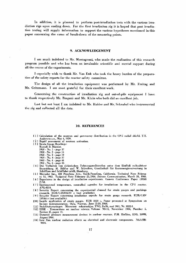
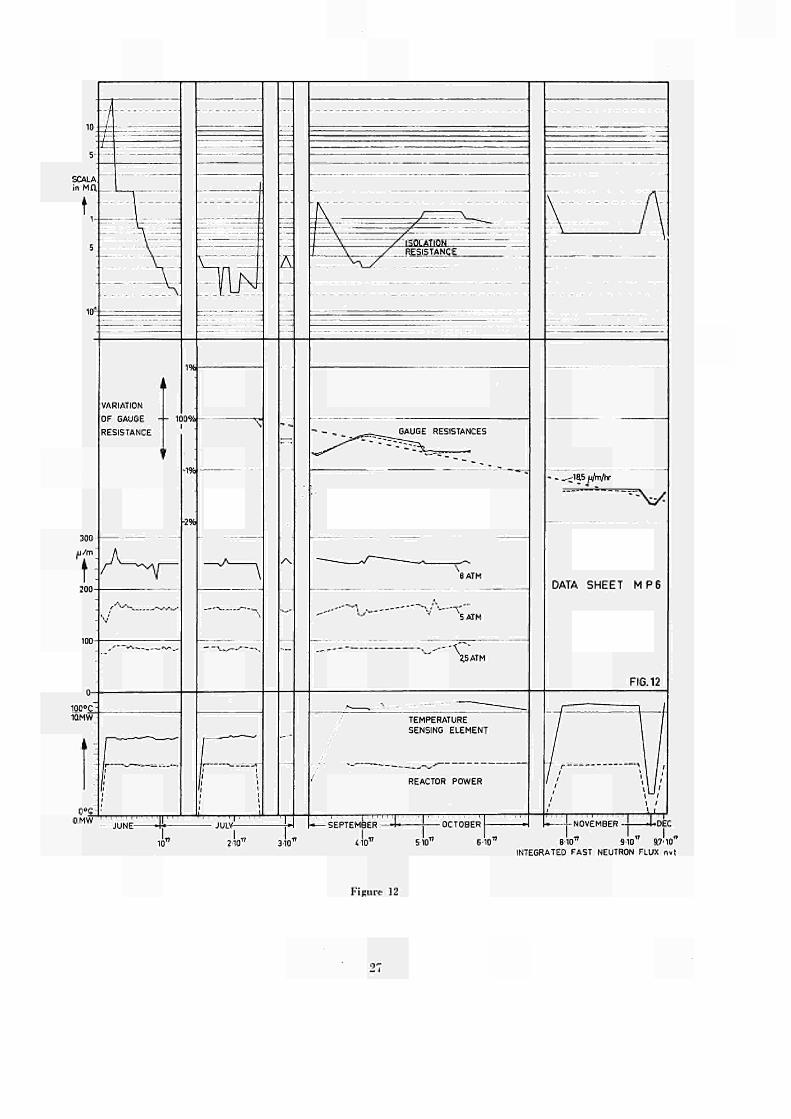
MP 6
All the data collected on MP 6 are graphically summarized in Figure 12. The various curves are identified and self-explain ing. In the following these curves will be discussed and interpreted.
1. Reactor Power
The reactor power has been constantly held at 5 MW apart from minor variations and various shut downs. During the summer shut-down between July 30th and September 14th, the composition of the core was changed. This affected the local flux distribution.-in the vicinity of the irradiation rig (see 2).
2. Temperature of sensing element
The average temperature during the first 6 weeks of irradiation amounted to 85" C with variations of the same order of magnitude as the reactor power. Due to a changement in core composition during the summer-shut down, the average irradiation temperature was increased to 106° C for the second irradiation period. This temperature increase was due to a higher gamma flux.
3. Isolation resistance
The isolation resistance showed an exponential decrease from the initial value during the first fortnight of irradiation. At an integrated fast flux of 1.5 . 1017 nvt the isolation resistance stabilized at an average value of 0.2 ΜΩ, increasing by a factor of ] 0 upon shut-down of the reactor.
It should be mentioned at this point that this behaviour of the isolation resistance was characteristic for all measuring points. Actually, for the three measuring points with weldable strain gauges this behaviour was absolutely identical.
The second irradiation period (after the summer shut down) gives an average value of 0.6 ΜΩ as stable isolation resistance in-pile. This might probably be due to the
14
change in composition of the core. The recovery of the isolation resistance upon shut down of the reactor did not change appreciably. A value of 2 to 3 ΜΩ is a realistic value for postirradiation measurements.
During a recent discussion with the manufacturer of the weldable gage it was communicated that the manufacturer is engaged in a classified project in which a.o. the effect of purity of the isolating material on isolation resistance is being investigated. Preliminary results indicate the possibility of a hundred-fold increase in isolation resistance during irradiation for highly purified isolation material.
4. Gauge resistances.
The resistances of both gauges decrease with integrated flux. At an integrated fast flux of 7.4.1017 n.v.t. (corresponding to an integrated thermal flux of 2.2 . 1020n.v.t.) the decrease amounts to about 1,5 % of the initial value (see dotted line). Under the flux conditions in the Ispra-I reactor a single strain gauge with out-of-pile bridge compensation would consequently exhibit a drift, due to radiation induced gauge resistance variation only, of 18.5 μ/τα/hr. Such a high drift value has never been measured during the experiment (see 6), indicating a rather high degree of compensation efficiency of the half bridge arrangement. In effect, the curves illustrate clearly that the radiation induced resistance variation of both active and dummy strain gauge is practically identical. The minor variations in the gauge resistances must be attributed to small temperature variations between subsequent measurements, either at the location of the measuring point, along the leading wires, or both. It should be noted however, that also during such minor deviations, the resistances of both gauges vary in the same way, indicating once more an efficient compensation.
5. Sensitivity
From the curves it follows that the average strain signals are:
at 2.5 atm : 85 μ/τα at 5.0 atm : 160 μ/να. at 8.0 atm : 250 μ/τα
The average strain signal is consequently proportional to the applied pressure within the limits of the experimental error. It is important to note that this proportionality was not disturbed with increasing integrated flux. Actually, up to October 15, 1964 (integrated fast flux of 5.8 . 1017 nvt) no major deviations were observed. Unfortunately, at that point the pressurizing system was contaminated, making further sensitivity measurements impossible.
Apart from the observed proportionality it should be mentioned that the measured strain signals correspond to the estimated values. Actually, the estimated value of 235 μ/m (see 5.1.) at 8 atm pressure becomes 260 μ/τα after correction for decreased Young's modulus at 100° C.
6. Drift As mentioned before (5.2.), systematic drift measurements have not been made
during this test series. Nevertheless, a few dozen drift measurements were performed, most of these on MP 5, 6 and 7. The average value of these measurements amounts to 2 μ/m/hr, maximum and minimum values being respectively 5 and 0.75 μ/m/hr. As above mentioned (item 4 of this chapter), these values indicate a rather high degree of compensation efficiency, and are comparable with out-of-pile drift values. It is intended to give much importance to drift measurement during the next test series.
At this point it should be mentioned that in the course of the measurements no detectable influence was observed of the helium flow rate. All measurements were thus performed in a stagnant helium atmosphere. The absence of such influence can be explained by the fact that each individual measuring point was completely protected from the atmosphere by means of high temperature strain gauge cement, a protection which apparently turned out to be efficient.
7. CONCLUSIONS
Reviewing briefly the results of the first stage of the experimental program on in-pile application of resistance strain gauges, the following conclusions can be made:
1. Resistance strain gauges are a possible means for in-pile strain measurements.
2. Weldable strain gauges of the coaxial type are very promising for such application.
3. Normal compensation techniques are also efficient for radiation induced parasitic effects.
4. The in-pile isolation resistance stabilizes at a relatively low value at an integrated fast flux of about 1.5 . 1017 nvt. For accurate measurements it will thus be necessary to realise efficient electrical screening of the bridge circuit.
5. During the initial period of sharply decreasing isolation resistance, correction for the effect of varying isolation resistance is possible.
6. The overall stability (drift) can be made of the order of magnitude of out-of-pile measurements by appropriate compensating techniques.
8. FUTURE EXPERIMENTS
The integrated flux obtained in the first tests series is :
Fast Flux: 9.7 .1017 nvt Thermal Flux: 3 . 1020 nvt
These values are relatively low, especially for the fast flux, as the main irradiation damage is thought to originate from fast neutron bombardment. Experiments are thus in preparation for strain gauge irradiation in the High Flux Reactor at Petten (Holland), in a fast flux position of 2 . 1013 nvt. One irradiation cycle of three weeks would thus correspond to an integrated fast flux of about 4 . 1019 nvt. These experiments are planned to be performed in spring 1966. Meanwhile, a second irradiation rig is prepared with weldable strain gauges, ready to be introduced in the Ispra-I reactor at Ispra. This rig should give additional information on the in-pile behaviour of this type of strain gauges, mainly with respect to the possible type of in-pile measurements (dynamic or static measurements, creep measurements).
16
In addit ion, it is p lanned to perform postirradiation tests with the various irra
diation rigs upon cooling down. For the first i r radiat ion rig it is hoped tha t post i rradia
tion testing will supply information to suppor t the various hypotheses ment ioned in this
paper concerning the cause of breakdown of the measuring points.
9. ACKNOWLEDGEMENT
I am much indebted to Mr. Montagnani , who made the realisation of this research
program possible and who has been an invaluable scientific and menta l suppor t dur ing
all the course of the experiments .
I especially wish to thank Mr. Van E n k who took the heavy burden of the prepara
tion of the safety reports for the reactor safety committee.
T h e design of all the i r radiat ion equ ipment was performed by Mr. Frei tag and
Mr. Gri tzmann. I am most grateful for the i r excellent work.
Concerning the construction of i r radia t ion rig and outofpile equ ipment I have
to thank respectively Mr. Bregani and Mr. Kle in who both did an excellent job .
Last bu t not least I am indebted to Mr. Ha ider and Mr. Schnabel who instrumented
the rig and collected all the data.
10. REFERENCES
[ 1 1 Calculation of the neutron and gammaray distribution in tbe CP5 radial shield. T.T. Anderson a.o., May 4, 1959.
Γ 2 ] Rapid assessment of neutron activation. [ 3 1 Strain Gauge Readings :
Russell B. Massler. 1958 No. 1 page 17 1958 No. 2 page 14 1958 No. 2 page 19 1959 No. 4 page 37 1960 No. 4 page 44 1961 No. 6 page 22.
Γ 4 ] Das Verhalten von elektrischen Dehnungsmeßstreifen unter dem Einfluß radioaktiver Bestrahlung. H. Bühler und W. Schreiber, Gesellschaft für Kernenergieverwertung in Schiffbau und Schiffahrt mbH, Hamburg. N
1 5 ] Microdot Inc., 220 Pasadena Ave., South Pasadena, California. Technical Note February 13, 1962. Technical Note February 25,1964. Private Communication, March 28, 1963.
[ 6 ] Experience in the design of irradiation experiments. Geneva Conference Paper (1958)
P/58. [ 7 1 Instrumented temperature, controlled capsules for irradiations in the CP5 reactor.
ANL6554. [ 8 ] Security Report concerning the experimental channel for strain gauges and packings
research. EUR/CIS/815/63 e (not available). [ 9 1 Security Report concerning irradiation capsule for strain gauge research. EUR/CIS'
139/64 e (not available). [10] Inpile application of strain gauges. EUR 2120 e, Paper presented at Symposium on
Incore instrumentation. Oslo, Norway, June 1519, 1964. [11] Stabiliteitsmetingen Microtest rekstrookjes. TNO, Delft, mei 1961, Nr. 30223. [121 IEEE Transactions on nuclear science. Volume NS11, November 1964, Number 5,
Section II, paper 10. [13] Dynamic pressure measurement devices in nuclear reactors. P.M. Hotline, IDO, 16999,
August 1964. Γ14] Low flux nuclear radiation effects on electrical and electronic components. NAASR
9634.
17


SCHEMATIC LAYOUT OF CORE
t THERMAL COLUMN
¿2\J IRRADIATION RI6. REACTOR VESSEL WALL.
THERMAL FLUX DISTRIBUTION
ALONG SAMPLE THIMBLES
NEUTRONS/cm2S
| J FUEL ELEMENT POSITIONS
τ — ι — ι — ι — ι — ι — ι — ι — ι — ι — ι — ι — ι — ι — r 10
1U0 200 ¿00 600 800 1000 1200 UOOmm
DISTANCE ABOVE LOWER GRID
SHIM RODS POSITION 8
POSITION 3
Figure 1 Figurr 2
f το CHIMNEY
DRIER
VENTILATOR
h i
OUT-OF PILE SYSTEM
LÜ
O
< u. a: 3 to ι
LU m
Q LU CL O
_J LU > LU
i
Half-Bridge C12/620 Budd R = 108.3D
Budd Cenent ConBt. Glas f iber
Pula Bridge ALE6DA Microdot H. - 237 .40 R
i s o l . " 3 6 M n
welded Const. Glas f iber
Half-Bridge C12/620 Budd H = 108.8 η E
i s o l . = ï5 0 H n
Budd Cernent Const. Coax
Thermocouple Chrome-Alumel
Half-Öridee ALE6A Microdot R = 120.2 α B
i » l . -7
5 " ° welded Const. Glas f iber
Half-Bridge C12/620 Budd R - 108.5 0 " i s o l . "
> 1 0 0 0 m
Cen.ALPI Baldw. Const. Glasf iber
Half-Bridge ALE 5A Microdot R » 61 .0 η R
isol .= > 1 0 0
° m
welded Const. Glas f iber
Half-Bridge 012/620 R = 100 R
i s o l . " Cem.ALP
Budd 3 η 43 Μη
1 Baldw. Const. Coax
ARRANGEMENT OF STRAIN GAUGES ON PRESSURE-
TUBE SURFACE OF ISPRA-I-RIG.
Figure 4 Figure 6
SECTION D-D
SECTION 127-27 SECTION 127-26
SECTION E-E
SECTION 127.25
ci i -
SECTION 127.28 VIEW -Y SECTION A-A SECTION B-B SECTION C-C
ASSEMBLY OF RADIATION EXPERIMENTAL CHANNEL
IN ISPRA I
' i ^ u r e 'Λ
21

1<I OJ
Figure 5

I O
Figure 7 Figure 8
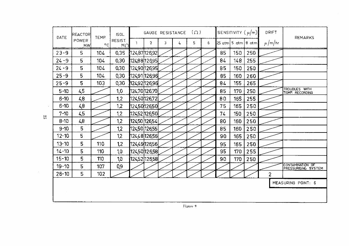
Figure 9
NOMOGRAM
i
m'1
TU
•m2
IL)
m"3
lU
m"4
lu
i r ïs
TU
m"6
IU
m"7
IU
m"8
TU
m"9
II)
mH0
l u
ipp.
101 1 o
2· O3
' & ■ (f ' 0 e 1 o
7 1 O8
' O9 ' o
1 0- o
1 1- o
12< o
1 3· io
1 4
'¡sol.
Figure 10 Fi ¡ru re 11
DEC
10" 910 9.7-10 INTEGRATED FAST NEUTRON FLUX nvt
Figure 12


ΊΜ'Γ..
»if! Il» m
m "jt'fi· m
Β** 3 id ■
! To disseminate knowledge is to disseminate prosperity — I mean
general prosperity and not individual riches — and with prosperity
disappears the greater part of the evil which is our heritage from ! disappears the greater part <
I ! darker times.
. . : ■
IH
I Î Ï .H- Î I . ,

£WIT?
SALES OFFICES ief
!A11 Euratom reports are on sale at the offices listed below, at the prices given on the back of the cover (when ordering, specify clearly the EUR number and the title of the report, which are shown on the cover). are 8nown on ine cuver β.
mÊSÊSÊKÊmmBÊ PRESSES ACADEMIQUES EUROPEENNES
98, Chaussée de Charleroi, Bruxelles 6
β!·,,_ „_____ „„.„.afifei
o o >
o Os
o
B a n T Ν· ÎLs£fé Générale 'BruxeUee
compte Ν 964.558, Banque Belgo Congolaise - Bruxelles
compte N° 2444.141,
Compte chèque postal - Bruxelles - N° 167.37,
Belgian American Bank and Trust Company - New York
compte No. 22.186,
Lloyds Bank (Europe) Ltd. - 10 Moorgate, London E.C.2.
Postcheckkonto - Köln - Nr. 160.861.
'iKJKfl!
OFFICE CENTRAL DE VENTE DES PUBLICATIONS
DES COMMUNAUTES EUROPEENNES
Wm
BELGIQUE _ BELGIË GRANDDUCHE ™
DE LUXEMBOURG
OFFICE CENTRAL DE VENTE DES PUBLICATIONS DES COMMUNAUTES EUROPEENNES 9. rue Goethe Luxemhonre Goethe Luxembourg
26. rue Desaix Paris 15'
mmm w f * îrfi ¿te *feÄ41^ÄÄ· wtí mm
'afi3»wíí;';T!
.VENTE EN FRANCE _ R „ ETIONS DES NEDERLAND JTES EUROPEENNES i f e v . ^ U J i J STAATSDRUKKERIJ
DEUTSCHLAND
BUNDESANZEIGER ITALIA
Postfach Köln 1 LIBRERIA DELLO SI
111 il ™» iiiiieite "-G v
■,o - ■ FRANCE
SERVICE DE DES PUBLICATIONS COMMUNAUTES EUROPEENNES STAATSDRUKKERU f^É
Christoffel Plantijnstraat Den Haag
3
dMflWf ^SSî' WwÀifWß$mmftæm wVfrwm mWWÏÏMMw^iWsa S» ■»irΉΒΉ» $*'%TÅ i rpRi'iammm M 'iiA*ï^^W''MÈMMW' S m
filte líll lfe^ Λ
s « i f e i Ë l K ^ mk
EURATOM — C.I.D.
-53, rue Bel l iard Bruxelles (Belgique)
ht»:.
rfï