Embed Size (px)
Citation preview
NORTHWEST BIOLOGICAL CONSULTING HABITAT RESTORATION - ENVIRONMENTAL PLANNING Cal. Engineering Contractors Lie. #599428
REWATERING CHANNEL 10 --....-.. -----------
IN THE RUSH CREEK BOTTOMLANDS,
MONO COUNTY, CALIFORNIA
1995 Stream Restoration Program
Submitted by:
Directed by:
Scott M. English Stream Restoration Specialist Northwest Biological Consulting P.O. Box 671 Ashland, OR 97520 (541) 488-1061
E. Woody Trihey Restoration Consultant T rihey & Associates 4180 Treat Blvd., Suite N Concord, CA 9451 8
December 1995
P.O. Box 671 • 324 Terrace street • Ashland, Oregon 97520 • (503) 488-1061 Fax (503) 488-6717

TABLE OF CONTENTS
Acknowledgments
Introduction
Construction Sequence
Permits/Waivers
Procedures for Restoration Treatment
Equipment, Materials, Labor & Supervision
Aerial Photograph 1 - 1995 Channel Overview
Figures:
Figure 1 - Project Location Map
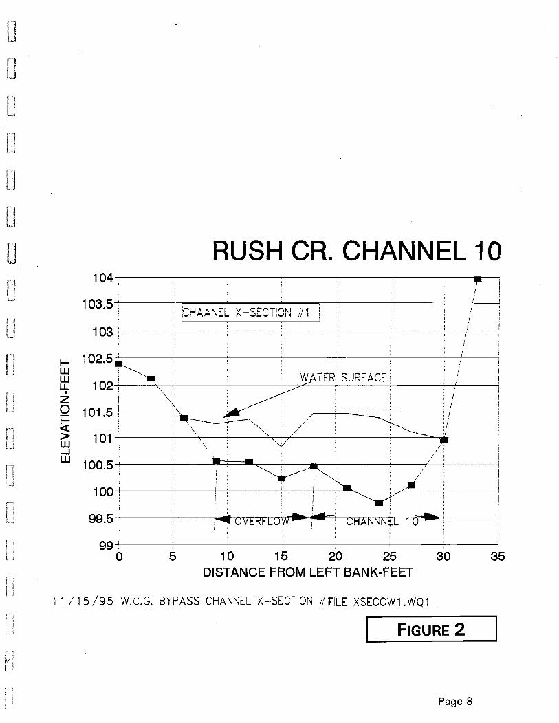
Figure 2 - Channel 10, Cross Section #1
Figure 3 - Channel 10, Cross Section #2
Figure 4 - Channel 10, Cross Section #3
Figure 5 - Channel 10, Cross Section #4
Figure 6 - Channel 10, Cross Section #5
Figure 7 - Profile Channel 10
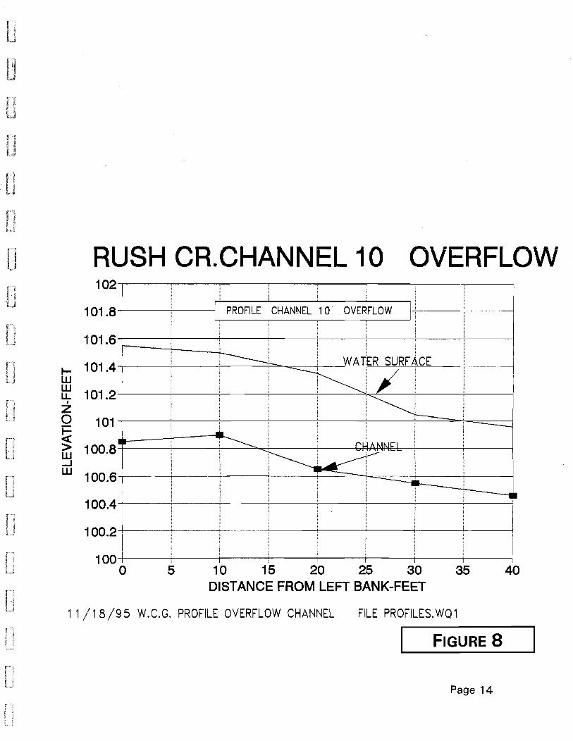
Figure 8 - Profile Overflow Channel
Before and After Photographs of Channel 10 Rewatering
Before, Plug Removal, Upstream end of project
After, Plug Removal
Before, Plug Removal, at Entrance to historic Channel
After, Channel Entrance After Rewatering
Before, Upper 450' Channel Section
After, Upper Section Rewatered
Before, Upstream View of Plug & Existing Vegetation
After, Upstream View Channel & Spoils Area
Before, Downstream View Before Rewatering
After, Rewatered Channel 10 Along Valley Wall
Page i
Page 1
Page 2
Page 3
Page 4
Page 5
Page 6
Page 7
Page 8
Page 9
Page 10
Page 11
Page 12
Page 13
Page 14
Page 15
Page 16
Page 16
Page 17
Page 17
Page 18
Page 18
Page 19
Page 19
Page 20
Page 20

f r "
TABLE OF CONTENTS (Con't)
Before, Dewatered Historic Channel 10
After, Rewatered Channel 10
Before, Upstream View of Channel 10 Valley Wall
After, Rewatered Channel Valley Wall
Before, Downstream View Dewatered terminus
After, Rewatered Channel 10 during mid-October
Before, Downstream View of Main Channel
After, Confluence of Channel 10
Before and After Close-Up Photographs:
Before, Upstream View of entrance during construction
After, Final Configurations of construction point bar
Before, Excavation/construction downstream
After, View of constructed channel
Before, Historical Channel 600' from Entrance
After, View of Rewatered Channel
Before, Dry Historic Channel 800' from Entrance
After, Rewatered Channel
Before, Historic Channel 1000' from Entrance
After, Rewatered Channel
Before, Historic Channel 1300' from Entrance
After, Rewatered Channel
Before, Historic Channel 1600' from Entrance
After, Rewatered Channel
Before, Historic Channel 1800' from Entrance
After, Large Pool
Before, View of Main Channel of Rush Creek
After, The Exit of Channel 10
Page 21
Page 21
Page 22
Page 22
Page 23
Page 23
Page 24 . Page 24
Page 25
Page 26
Page 26
Page 27
Page 27
Page 28
Page 28
Page 29
Page 29
Page 30
Page 30
Page 31
Page 31
Page 32
Page 32
Page 33
Page 33
Page 34
Page 34
Appendix 1 - Design Considerations for Rewatering Channel 10
Appendix 2 - Letter of Authorization
Appendix 3 - Conditional Waiver

ACKNOWLEDGEMENTS
Many people and organizations contributed their time and talents to make
rewatering of Channel 10 a success. The contributions of the following individuals
are greatly appreciated.
TeCHNICAL ADVISORY COMMITTEE
Jim Canaday, California Regional Water Quality Control Board Christopher Hunter Ilene Mandelbaum, Mono Lake Committee Brett Matzke, California Trout Lucy McKee, U.S. Forest Service William Platts, L.A. Department of Water & Power Richard Ridenhour Jill Shirley, National Audubon Society Gary Smith, California Department of Fish & Game William Trush Mike Verzatt, Facilitator, EI Dorado County Superior Court Bill Hasencamp, L.A. Department of Water & Power
PLANNING TEAM
Reg Cullen, Trihey & Associates Scott English, Northwest Biological Consulting Mitchell Katzell Steve Koskella Eric Larsen Scott Stine Tom Taylor, Trihey & Associates Woody Trihey, Trihey & Associates Peter Vorster

ACKNOWLEDGEMENTS
ON SITE WORK
Channel 10 Entrance Design:
Construction Inspection & Supervision:
LADWP Equipment Crews: Photo Documentation: Video Documentation: Final Project Inspection
Scott English Reg Cullen Scott English Steve Koskella Richard Williams, Supervisor Linda Chesney Steve Koskella Woody Trihey
ii
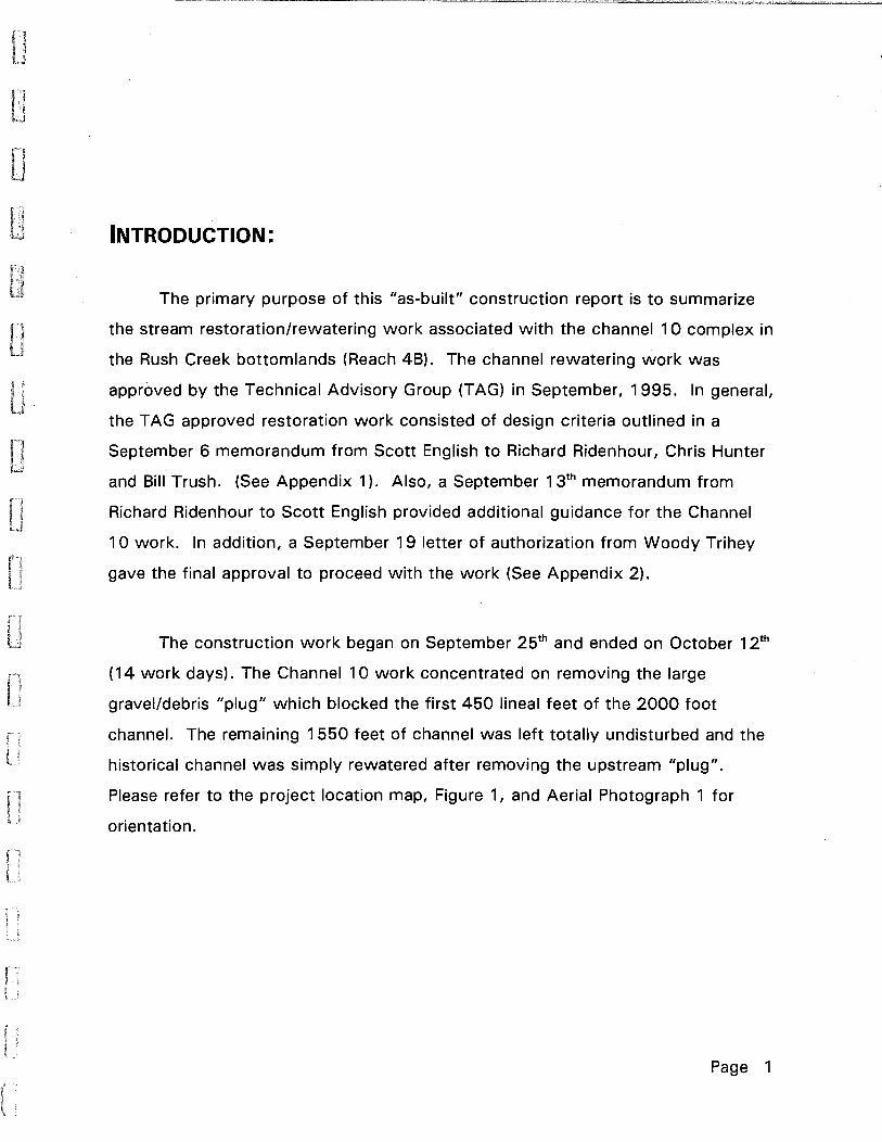
INTRODUCTION:
The primary purpose of this "as-built" construction report is to summarize
the stream restoration/rewatering work associated with the channel 1 0 complex in
the Rush Creek bottom lands (Reach 4B). The channel rewatering work was
approved by the Technical Advisory Group (TAG) in September, 1995. In general,
the TAG approved restoration work consisted of design criteria outlined in a
September 6 memorandum from Scott English to Richard Ridenhour, Chris Hunter
and Bill Trush. (See Appendix 1). Also, a September 13th memorandum from
Richard Ridenhour to Scott English provided additional guidance for the Channel
10 work. In addition, a September 19 letter of authorization from Woody Trihey
gave the final approval to proceed with the work (See Appendix 2).
The construction work began on September 25th and ended on October 12th
(14 work days). The Channel 1 0 work concentrated on removing the large
gravel/debris "plug" which blocked the first 450 lineal feet of the 2000 foot
channel. The remaining 1550 feet of channel was left totally undisturbed and the
historical channel was simply rewatered after removing the upstream "plug".
Please refer to the project location map, Figure 1, and Aerial Photograph 1 for
orientation.
Page 1

CONSTRUCTION SEQUENCE:
The following is a general outline of the construction sequence which was
followed to implement the Channel 10 rewatering. Please refer to Appendix 1 for
more specific design information.
1. Final on-site review with LADWP construction supervisors and Stream Restoration Specialist.
2. Mobilization of crews, equipment and materials.
3. Final staking and project layout.
4. Review of project on-site with all Construction Personnel.
5. Installation of precautionary measures (oil booms, etc.)
6. Photographs were taken of the project from established photo points
7. One access route at the upstream end of the project was utilized which was the "I east impact route".
8. The initial Channel 10 entrance and upper channel planform was cleared brush which consisted primarily of Wildrose, Sagebrush, rabbitbrush and dead willows.
9. A one acre area adjacent to the upper channel was cleared of brush and graded to receive the excavated sediment materials from the channel work.
10.The channel planform (e.g. Point bars, channel banks, etc.) was roughed in for approximately 450 feet and the excavated plug materials were deposited and graded into the adjacent spoils site.
11.Six groundwater monitoring wells were installed along two transect lines which crossed the interfluve area between Channel 1 0 and the main channel of Rush Creek. Refer to aerial photograph 1 for their locations.
Page 2

12.The channel entrance was breached, the stream rewatered and work on the channel entrance, overflow side channel and point bars was completed. Refer to the following "Before & After" photographs for overviews of the construction work.
13.Approximately 40 CFS (2/3 of incoming flow) occupied Channel 10 and 20 CFS (1/3 of flow input) discharged into the overflow (side) channel. Please refer to Figures 2-8 for cross sections and profiles of Channel 10 and the overflow channel.
14. The overall gradient of the excavated channel was approximately % percent. The bed topography was fairly uniform and matched existing channel topography. (See Figures 2-8)
15.The existing large woody debris, including the old beaver dams and the grasses and sedges were left undisturbed.
16.Final grading of the channel, entrance bar and adjacent spoils area was completed. Brush and native seeds (sagebrush, rabbitbrush, etc.) were scattered over the spoils site.
17. The equipment access route was graded and all the oil containment equipment removed from the creek. All the equipment was removed from the site.
18.Final photographs and "as-built" cross-sections and profiles were completed for the project.
PERMITS/W AIVERS:
Permits and/or waivers were required by the Lahontan Regional Water
Quality Board and the Army Corp's of Engineers. In general the permit conditions
from the above agencies required a variety of precautionary measures be followed
to avoid adversely affecting water quality. Copies of permits/waivers for the
Channel 10 work are provided in Appendix 3. All the waiver conditions were
complied with.
Page 3

PROCEDURES FOR RESTORATION TREATMENT: Stream restoration guidelines adopted by the RTC in August, 1993, for on
the-ground treatment were applied during the Channel 10 work. These guidelines
included:
1) Light-handed restoration techniques are to be used at all times;
2) Hand crews shall be given emphasis over mechanical equipment where feasible;
3) Work shall seek a self-cleaning, self-functioning nature; and
4) Materials shall be native to the basin.
In keeping with the above guidelines and the permit/waiver considerations the
following construction procedures were followed:
1) Hand labor crews completed as much of the work as was feasible
2) Equipment crews were only utilized where the amount of work was beyond the capabilities of the hand labor crews.
3) Wetland areas were avoided and not impacted by the work.
4) The equipment access area was limited to entry/exit points along Rush Creek to minimize impact to the aquatic system.
5) Native cobble material from the excavation work was utilized to provide streambed material where it was needed on Channel 10.
6) Excess sediments removed from the reconstructed channel were utilized in other parts of the Channel or were disposed of in adjacent upland depressions which were barren cobble areas and/or upland scrub vegetation.
7) Channel 10 was reconstructed (e.g., point bars, stream banks, streambed topography, etc.) so that the stream will be self-maintaining.
8) Work on the channel progressed from the upstream to downstream to minimize overall impacts.
9) Precautionary measures (e.g., oil containment booms/pads, straw bales and frequent equipment inspections) were implemented throughout the length of the project.
Page 4

EQUIPMENT, MATERIALS, LABOR & SUPERVISION:
The Equipment utilized on Channel 10 work included:
• One Cat. 977 Tracked Front-end Loader
• One John Deer 310 Backhoe with 24" Bucket
• One Contractor Pump with 1 Y2" hose
• 8mm Video Camcorder and 35mm Camera
• Misc. Hand Labor Tools (rakes, digging bars, shovels, etc.)
The Material utilized in the reconstruction and rewatering of Channel 10 included
the following:
• Oil Containment Booms and Oil Absorbent Pads for emergency use
• Six 10' (length) x 6" (diameter) PVC Pipe with Caps for the six ground water monitoring wells
• Twelve Straw Bales and Ten 5' lengths of Y2 inch rebar for use in constructing two temporary sediment control stations
• Twelve Sacks of Redi-mix which were utilized to seal the six monitoring wells
The Labor required to complete the Channel 10 work consisted of:
• One DWP Backhoe Operator
• One DWP Tracked Loader Operator
• Two DWP MCH Laborers
• Equipment Maintenance/Fueling every 2-3 working days by DWP Crew
Supervision of the On-Site A-4 Channel work was provided at all times by the
Stream Restoration Specialist (Scott English) and his Part-time Assistant (Steve
Koskella). A DWP Supervisor (Richard Williams) was in the vicinity during most of
the channel work. The RTC Consultant (Woody Trihey) inspected the work and
minor channel modifications were carried out in response to his final inspection.
Page 5

. --
. ,
-'tit: '"
-t .
Ii
Ii
•
• •
, ' . .... 'I .l . . •
, .
..
• • • ••• • ' . ."'. .-~: ..,Or: ' ::_ .~ .. :. ",. ,~."!" ~: \" .
, . " , .,
,
"
... ,--
~ -, ... ' .. .... ""; ~ ~ .. .. ' ... .-,: ',.
,
'.
. . , •
\ ....
AERIAL PHOTOGRAPH 1
Page 6
• , ,
• ,
• ,:<, .. '. ," .. ' - .. ' .,' "' '. .~; --'";:;,. .
,-'.

Figure 1; Location of Rush Creek Pilot Project to Rewater Portions of
40io ,/
' .. ---.,..
, ~
/ .... ~ ,,,::. ... ,
Channel 10.
8A ",,,r- --- - .. ---- -- ...
/ ... " , /~---, 8B \ -- ' ..... ",- '
4Bib
-... I
~.----
,t' 9 ........ ---~ . / , __ J " , ,,--~ ... .,..""/ /'
I' I , I
,- __ J
... ' '... ;,,"---, I ......... __ ..-' '-__ .I
') 4Biia ".,,/ 4Bii I ,.- __ ----- .. -........ , ,I" ,/ ... / r '"
4Bii
" ,J ... , ' .... , ,/
'....... ,/ ---"'" 48iib
o
~/ /'
FEET
SCALE
, 1
" ' , ,,-.. } ! '---; ')
lOB I f / / lIpper / \~ ....
/~ _---,/ J 10
,/ ' ~--) ( ,-,,---.,,' 10,
t"'""
W a: ::) o -900 ILL
I
I , , ,/ , "-
" Q)
en co a..
RUSH CR. CHANNEL 10 104~:--------------------~------~------------------~~
I /
103.5~!------~-i-~H-A-·-AN-'E~,~v--S~-~-T-,n~~-'-i:-·1~~--------------~~!--~ IV ,.., I... 1\ - I:..v IVI~ 'ff i
103 -+- .---i-____ ~- ----'-- ---1-' -_.,
99+!-----~------~----~,------~,------~------~J ----~
o 5 1 0 15 20 25 30 35 DISTANCE FROM LEFT BANK-FEET
11/15/95 W.C.G. BYPASS CHANNEL X-SECTION #tILE XSECCW1.WQ1
r I FIGURE 2
Page 8

RUSH CR.CHANNEL ;0"
!
1 04+------!~HANNEL X-SECTION #2
i
Y ,( j;
!
103+!--------~------~--------~--------------+i~--------
~ i ~ W ! ! u.. i i
I 102+:--------~------~·--------~· --------~----~i~------~ a WATER SURF ACE I >~ 101 ;/ ~'\
~ ~'/ }\'~ 100 : .: If .1 \.- -=
, i '\ ,/i i \ • / I :'\ __ ; I\i /!
99 :1,' :,,!i,o··· V---------ERFLO w' ., 'i"! i '.. i / !
, ! I
i ,~;V- I L CHANNE~, ~ .CHANNEL 1 0 ~! :
98+;,--------~~·--------c~'--------~------~------~------~I, ) j i
o 10 20 30 40 50 60 DISTANCE FROM LEFT BANK-FEET
11/15/95 W.C.G. BYPASS CHANNEL X-SECTION #2 FILE XSECCW.WQ1
FIGURE 3
Page 9

l-W w lL.
I
Z 0 l-« > W ....J w
RUSH CR. CHANNEL 10 105 I
i
104 j\\ ~ ___ -'-----itHANNEL X -SECTION #3 t-! -----+-------! ___ ~ !
~ [ \
103 i \ \ I \
! .. i \
1021 \
! i I
101 I I i
i 100 :
I i
99-+
i \
\ \ \
/; .! /
WATER SlJREA!CE / i • /
!/ / ! ~
! /
98···.l.i,·------~------~--------r_------~------T_------,. :- I I i i o 10 20 30 40 50 60
DISTANCE FROM LEFT BANK-FEET
11/16/95 W.C.G. BYPASS CHANNEL X-SECTION #3 FILE XSECCW3. WQ1
FIGURE 4
Page 10

RUSH CR. CHANNEL 10 104~i--------------~--------------~------~----~
103~----i~HANt~EL X -SECiiON #4 II ~------~------~'~
/l ,. /i !
! f
~ 102"\ I
i i
-;
~ -\ WATER S~RFACiE I ~ 101~--~'~--~------~~--~7~/--~-~-----~.----/~~-------
~ 100+\-------~~·~-----+-------+------~~~t-----~----~ WI ~ If
I . ~~( 99+!----------------~---~~~!-------+~1 ------~------_4
: : 98+i--------~I------~--------+!--------~! ------~i------_4
o 10 20 30 40 50 60 DISTANCE FROM LEFT BANK-FEET
11 /17/95 W.C.G. BYPASS CHANNEL X-SECTION #4FILE XSECCW4.WQ1
FIGURE 5
Page 11

RUSH CR. CHANNEL 10 105\
I i
104Ti-----o--~:C~.H~A~NN~E~L~X-~S~E~C~T~IO~N~#~/5~--~-----:-----T--~/~~
i :/ I" /
103+:------------~----~----~----~------~----/+!i----~
m ~. WATE~,SURFACk f z 1 02 ! "" . ji ! I" ,/ o .~ / j ~ \ / / >< 101+-----~~\--~---1~(~------+-----~----~.~/----~----~
\, / / W i \"; ~ ," \ , if
w 1 :-+-i -----;...----St-! -"~"--'------+'-----:]f-/-?-~-"-' _---"-__ ~ i ~i I .." i
98+:------~i ----~i----~i------Ti----~!------~i-----4------! o 5 10 15 20 25 30 35 40
DISTANCE FROM LEFT BANK-FEET
11/17/95 W.C.G. BYPASS CHANNEL X-SECTION #5 FILE XSECCW5.WQ1
FIGURE 6
Page 12

RUSH CR. CHANNEL 10 102
101.5 I
. .
WATER SURF ACE
pROFILE , CHANNEL 1 0 I I
101
~ 100.5 w
100 I w LL. ,
I z 0 I
~ 99.5
CHANNEL
~ 99 w ...J w 98.5
98
97.5
971 I
0 50 100 150 200 250 300 350 STATION-FEET
1 1 /1 7/95 W. C. G. PROFILE BYPASS CHANNEL FILE PROFILEB. WQ 1
FIGURE 7
Page 13
RUSH CR.CHANNEL 10 OVERFLOW 102
101.81 101.6
-+----:-----11 PROFILE CHANNELl 0 OVERFLOW I
t- 101.4 WATER SURFAcE
w w
101.2 IJ.. I
Z 0 101 t-
~ 100.8 w ...J w 100.6
! 100.4 '
100.21
100 ! i I
0 5 10 15 20 25 30 35 40 DISTANCE FROM LEFT BANK-FEET
11/18/95 W.C.G. PROFILE OVERFLOW CHANNEL FILE PROFILES.WQ1
FIGURE 8
Page 14

BEFORE AND AFTER PHOTOGRAPHS
OF THE CHANNEL 10 REWATERING
FROM PHOTO POINTS 1 - 9
Page 15

PP1 a Before: Upstream end of project before initial 450 ft. of the historical Channell O. The existing side channel of Rush Creek has an estimated discharge of 60 CFS.
After : The large gravel & debris plug was removed from the entrance to the historical Channel 10. A point bar & cross-over bars were constructed to control the flows between the existing side (overflow) channel (left) and Channell 0 (right). The overflow side channel has - 20 CFS & Channell 0 contains - 40 CFS.
Page 16

PP2 Enl~a"C8 to i 10 entrance was designed to split off from the large existing side channel of Rush
Creek.
After: The existing was i to of the flow of the upstream side channel (-20 CFS) and Channel 10 (right) was configured to hold -2/3 of the existing side channel discharge (- 40 CFS). The point bar and Channell 0 cross4 sections/profiles were designed to allow Channel 10 to function as the dominant channel.
Page 17

PP3 Upper section of Channel 10 depicting the gravel/debris plug before exca',ation and rewatering .
Aher: The upper section of Channel 10 after the sediment plug was removed and the channel rewatered with -40 CFS . One of six pzeiometers is located next to the willow, along the left bank of Channel 10.
Page 18
-
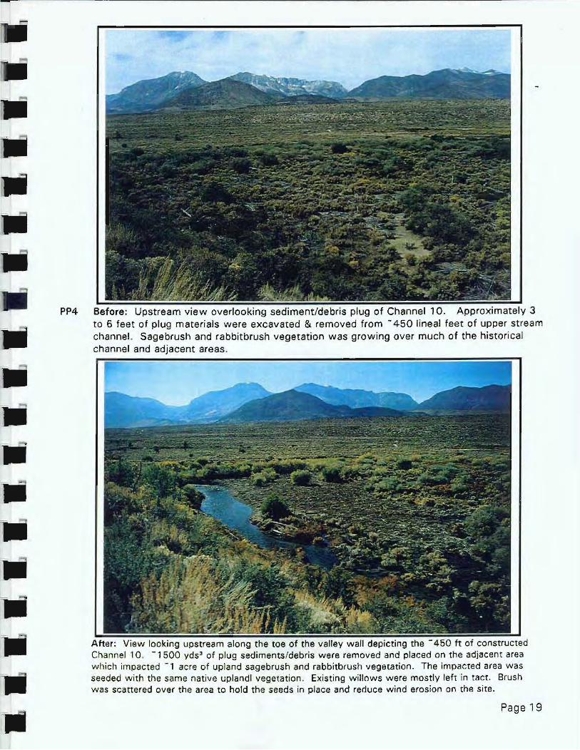
PP4 Before: Upstream view overlooking sediment/debris plug of Channel l O. I 3 to 6 feet of plug materials were excavated & removed from - 450 lineal feet of upper stream channel. Sagebrush and rabbit brush vegetation was growing over much of the historical channel and adjacent areas.
After: View looking upstream along the toe of the valley wall depicting the constructed Channel 10. -1500 yds;o of plug sediments/debris were removed and placed on the adjacent area which impacted -, acre of upland sagebrush and rabbitbrush vegetation. The impacted area was seeded with the same native upland! vegetation. Existing willows were mostly left in tact. Brush was scattered over the area to hold the seeds in place and reduce w ind erosion on the site.
Page 19
,. •
•
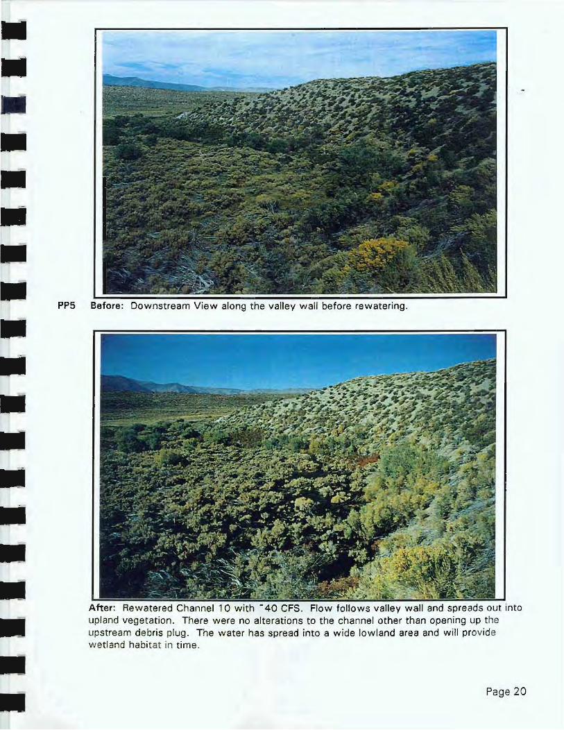
PP5 Before: Downstream View along the va lley wall before rewatering .
i and spreads out into upland vegetation. There were no alterations to the channel other than opening up the upstream debris plug. The water has spread into a wide lowland area and will provide wetland habitat in time .
Page 20

PP7 depicts the dewatered historical channel as toe of the slope.
After: The rewatered Channel 10 as it flows around the toe of the valley wall. No channel work was required here. The 40 CFS flow occupied the historical stream planform and streambed topography_
Page 21

ppg Before: Upstream view depicts the dry historical Channel 10 as it follows the valley wall. Note the large and numerous dead cottonwood trees within this interfluve area.
. The rewatered Channel 10 flowing along the toe of the va lley wall. A channel cuts across the big bend . Approximately 40 CFS of discharge occupied the channel in mid-October. Other than re watering, no other work was done in this reach .
Page 22

PP9 I withe dew ate red 10 as it joins the main channel of Rush Creek. No channel work was done other than rewatering the channel.
After: The historical Channel 10 was rewatered with - 40 CFS during mid·October, 1995. The large pool is - 4·5 feet in depth, 30 feet wide and - 250 feet long.
Page 23

-III III III III III
III III
.. III ..
PP1' Downstream view of the main channel of Rush is along the dry wi llow/gravel berm on the right. This photograph as taken several days before Channel 10 was rewatered .
After: The photograph depicts of Channel 10 with the main channel of Rush Creek. The 40 CFS flow from Channel 10 enters the main channel at severa l points along the right bank. The dominant flow enters in the foreground. The configuration could change in time.
Page 24

BEFORE AND AFTER CLOSE-UP PHOTOGRAPHS
OF THE CHANNEL REWATERING;
CHANNEL ENTRANCE AT STATION 0 + 00 TO THE CONFLUENCE WITH THE MAIN CHANNEL
AT STATION 20 + 00
Page 25
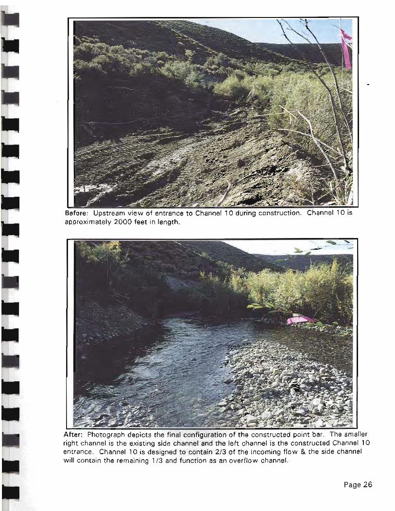
Before: Upstream entrance to Channell 0 dur;na Cons1tru'C!;"n. approximately 2000 feet in length.
After: Photograph depicts the final configuration of the constructed point bar. The smaller right channel is the existing side channel and the left channel is the constructed Channell 0 entrance. Channell 0 is designed to contain 2 /3 of the incoming flow & the side channel will contain the remaining 1/3 and function as an overflow channel.
Page 26

Before: Photograph depicts excavation /construction underway just downstream entrance to Channel 10. Removal of the gravel/debris plug took place from the entrance to a point 450 feet downstream.
i of the constructed channel. Sloping. armored streambanks i were constructed along a planform which followed the toe of the valley wall. After the revegetation of the banks the channel is expected to remain relatively stable through a range of discharges.
Page 27

channel entrance. No channel work was done from station 4+50 to station 20+00.
After: rewatered channel with ~ 40 CFS. toe of the valley wall for most of its' 2000 foot length. The channel is approximately 22 feet wide and 2 1/2 feet deep.
Page 28

..
Before: Depiction of dry historical channel approximately 800 feet downstream from entrance .
After: Rewatered Most of the habitat appears to glides and pools with depths varying between 2 & 4 feet and with velocities of approximately 1-2 FPS. Waterfowl were seen utilizing this habitat.
Page 29

Before: Historical Channel 10 approximately 1000 feet downstream from channel entrance.
;;~:~i;;g~;;';; run depths of 1-2 feet and velocities of 2-3 feet per second. Abundant woody debris can provide trout habitat and invertebrate production.
Page 30

• chanr1el at approximately 1300 feet downstream
from the entrance . The gravel bed channel can provide spawning habitat and other fish and wildlife benefits .
. View of rewatered channel with approximately 40 CFS . will eventually provide wetlands and riparian vegetation.
Page 31

•
i 10 approximately 1600 feet I entrance. This reach is characterized by old beaver dams and abundant supplies of large and small woody debris.
After: The rewatered channel provides a variety of excellent deep water and wetlands that will provide habitat for fish and wildlife.
Page 32
Ii iii iii iii iii iii
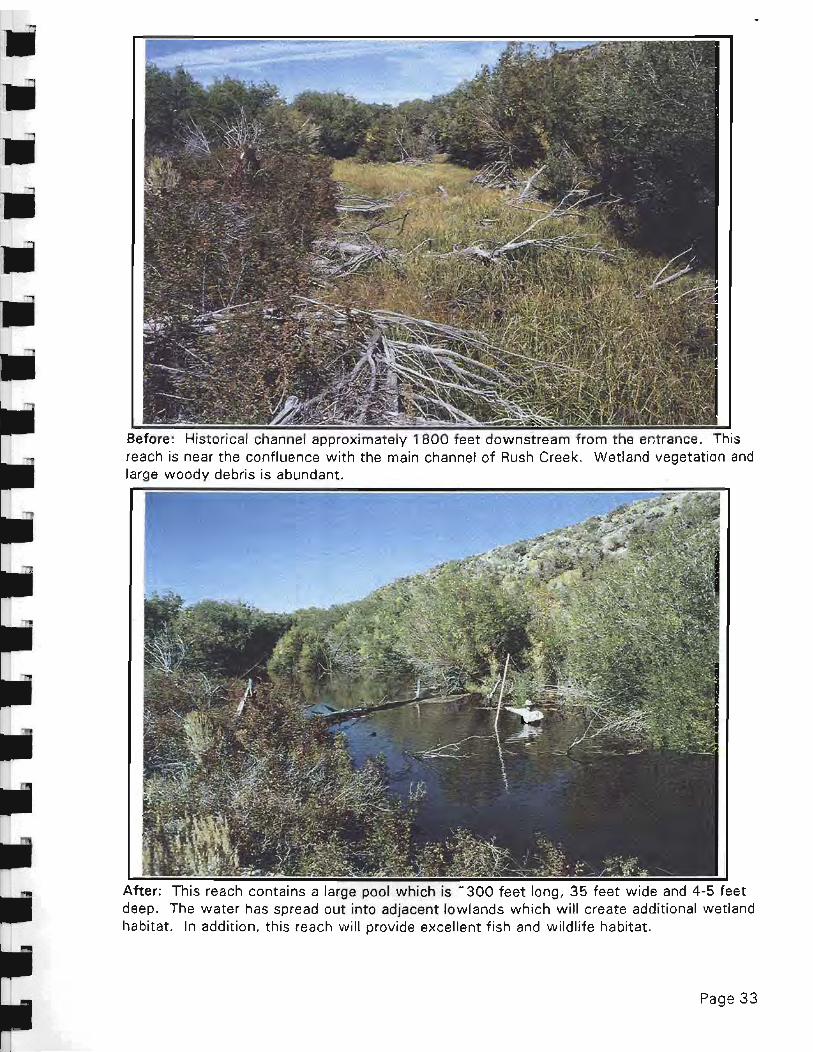
Hi"torical channel approximately 1 aoo feet downstream from the entrance. j
reach is near the confluence with the main channel of Rush Creek. Wetland vegetation and large woody debris is abundant.
~======
After: contains a large pool which is - 300 feet long, 35 feet deep. The water has spread out into adjacent lowlands which will create additional wetland habitat. In addition, this reach will provide excellent fish and wildlife habitat.
Page 33

.. ..
..
.. waf main channel of Rush Creek. The confluence of Channel 10 is on the left.
After: The exit of Channel 10 is along upper left Channel 10 enters the main channel in several places along the main channel.
Page 34

ApPENDIX 1 DESIGN CONSIDERATIONS FOR REWATERING THE
CHANNEL 10 COMPLEX

I I
~~ oc'...~~ ~~i. NORTHWEST BIOLOGICAL CONSULTING
HABITAT RESTORATION - ENVIRONMENTAL PLANNING Cal. Engineering Contractors Lie. #599428
To: Richard Ridenhour, Chris Hunter and Bill Trush
From: Scott English
Date: September 6, 1995
Subject: Response to Your Memorandum of August 2, 1 995
. OVERVIEW
This memorandum is a response to your request of Aug. 2, 1995, for
design information regarding the rewatering of the Channel 10 complex
through the Channel 10A alignment that follows the right valley wall.
Please refer to Figure 1 and Aerial Photograph 1 for the location of the
proposed channel work.
The overall concepts for rewatering the channel, construction
techniques and Permit requirements are very similar to the plans and designs
for rewatering the Channel 10B linkage. Please refer to the "Workplan for
Rewatering Portions of Channels 9, 10B, and 10 in the Rush Creek
Bottomlands, Mono County, California", August 1994, by Trihey and
Associates. In addition, the rewatering of the Channel 10 complex,
including Channels 10A, 1 OB, Channel 10B linkage and Channel 10 was
generally described in a June 1994 Report (Stine, English & Taylor) to the
RTC "Feasibility of Rewatering Abandoned Channels of the Rush Creek
Bottomlands, Mono County, California."
Rewatering Channel 10A would simply entail moving the channel
entrance - 900 Ft. upstream from the previous 10B linkage location. The
primary benefit of implementing this concept would be to gain an additional
- 800 Ft. of rewatered channel and riparian habitat as compared to the
previous Channel 10 linkage plan. In addition, the channel alignment off the
Rush Creek side channel appears to offer good hydraulic control.
P.O. Box 671 • 324 Terrace street • Ashland, Oregon 97520 • (503) 488-1061 Fax (503) 488-6717

Response to Your Memorandum of August 2, 1995 Sept. 6, 1995 Page 2
DESIGN CONSIDERATIONS
The major design considerations for rewatering the 1 OA channel are
as follows:
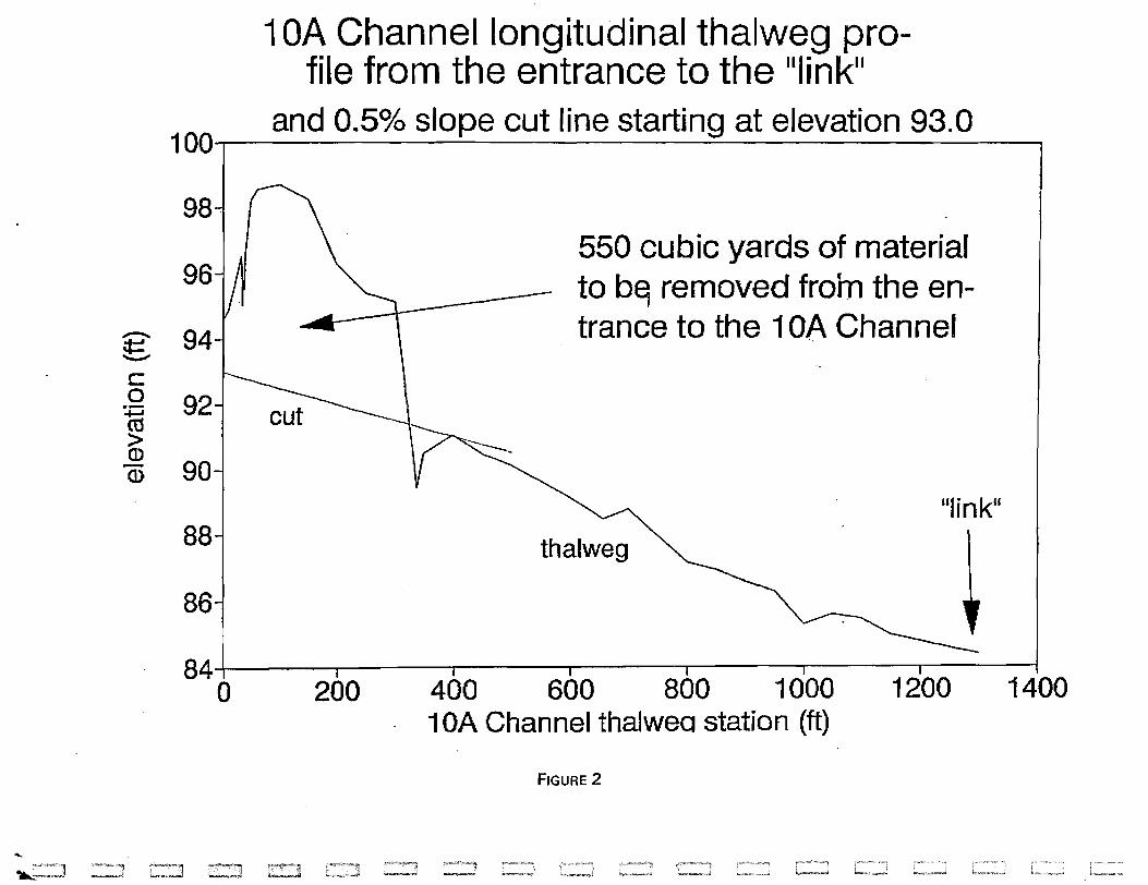
• Approximately 350 feet of channel with an eight foot bottom width and
2: 1 side slopes would be excavated to reconnect approximately 1900
feet of the Channel 10 system to Rush Creek (Figure 1). The elevation
of the land surface through which Channel 10A would be excavated is
approximately 6 feet higher than the desired grade, and therefore the
excavation would require the removal of approximately 550 cu. yds. of
alluvial material and debris (Figure 2). The Channel 10A Planform is
illustrated on Aerial Photograph 1.
• The gradient of the excavated channel would be approximately 0.5%
(Figure 2).
• The bed topography would be uniform gradient and where feasible would
match existing channel topography (Figure 2).
• The entrance to the channel system is designed for a flow of
approximately 5 CFS at the stipulated flow of 47 CFS in Rush Creek
during the summer of a normal runoff year. A bar and pool would be
constructed in Rush Creek (side channel) to provide appropriate hydraulic
conditions at the entrance to the 10A Channel. The upstream bar would
separate the flow into two channels (Rush Creek Side Channel and 10A
Channel) and a constructed downstream bar on Rush Creek Side Channel
would help control the water level (Figure 3).
• The side channel of Rush Creek contained approximately 1/3 of the total
discharge of Rush Creek. The 10A Channel is designed to contain
approximately 1/3 of the flow in the Side Channel. For example, a total
discharge of 47 CFS in Rush Creek would yield -15.5 CFS in the Side
Channel and the 10A Channel would receive 1/3 of that discharge, or
approximately 5 CFS (Figures 4 and 5).
• The existing large woody debris, including the old beaver dams, and the
grasses and sedges will be left undisturbed.
• No Limiter Logs will be placed at the entrance to the 10A Channel.

. Response to Your Memorandum of August 2, 1995 Sept. 6, 1995 Page 3
DEPOSITION OF EXCAVATED MATERIALS
The disposal of excavated materials (alluvial sands, gravels and
debris) from the 10A Channel work will be deposited and graded into upland
areas adjacent to the 10A Channel. No wetlands or riparian vegetation will
be impacted by the excavated materials. The materials (estimated at 550
yds3) will be spread around rather than concentrated and will be reseeded
with native sagebrush, bitterbrush, rabbitbrush, Indian rice grass and other
upland plant varieties. Please refer to aerial Photograph 1 for the proposed
locations of the excavated material.
LABOR AND EQUIPMENT NEEDS
(Estimated 15 Full Work Days)
The following labor and equipment is requested:
• One tracked Hydraulic Excavator, with operator or
• One Tracked Loader (D-7 or Equivalent), with operator
• One Cat 910 Articulated Loader, with operator
• One Cat 950 or equivalent Front End Loader with operator
• One JD 310 Backhoe, with operator
• One or two standby Dump Trucks
• 2 hand Laborers
• Hand tools, Fire Pump hose, strawbales, Oil Containment boom, etc.
ESTIMATED PROJECT TIME
I estimate that the project will take 15 to 20 Work Days to complete.
Stream Restoration Specialist - 20 Days
Stream Restoration Field Assistant - 1 5 Days
Equipment Operators - 1 5 Days
Laborers -15 Days
If feasible, I would like to begin work with the equipment and crews
on Monday, September 25, 1995.
cc: Woody Trihey

Figure 1; Location of Rush Creek Pilot Project to Rewater Portions of
8
40iu " /' ...-"
... ."::.,,,
.. ---"
Channel 10.
8A ".".-----_ ..... _-----
,/' , , , /~ .. -__ 88 \ -- . ,
-- ---.. / ~,..--~-... ~ / 9 ' ..... ---{
/' , __ J 4Bib ", , ,~ , ",",-#,-' / ,- __ oJ'
" I , .. I -, ' '. ,---, I
......... -,,""" " .I -- - .. _\ 4Biia ",/ 4Bii
, _----0.. /' 1",.".,---...... ...." I
( t ',/ , ,I'
" " ,~ / " '
4Bii
....... .,../ ..... _-, 4Biib
o
-:./ /'
FEET
I I I I I I
... I ,,_":'" I
, ,~_~.,) i , ;" I
1 OB! f { " upper ,I \ '--'//
_-_ .... ,-" )~ 10
/' / ,;
~--) ( l~---'J
lOA
900
~~~~~~~~··~·--··-····---··--~_··-·I SCALE
, , , , /. ,
"' . ... _-
..... 1"-'="1 ~ ,
10A Channel longitudinal thalweg profile from the entrance to the IIlinkll
and 0.5% slope cut line starting at elevation 93.0 100~'--------~~--------~----~------~
98
96
£ 94 '--"
c o -- 92 ro > (])
CD 90
88
86
550 cubic yards of material to b~ removed froin the entrance to the 10A Channel
"linkll
thalweg
841 I I I I I I I o 200 400 600 800 1000 1200 1400 10A Channel thalwea station (tt)
FIGURE 2

"- f:~:. J -...
Estimated side channel cross section at the entrance to the 1 OA Channel
95~1--------------------------------------~
94.5 WSEL of 94.6 ft at a side channel discharge estimated at 65 efs ,
94
£ 93.5 Elevation of 93.0 estimated for the '-"" bed of entrance to the 1 OA channel c 0 93 with an upstream bar seperating flow .. .-ro into two channels and a downstream > Q)
92.5 bar acting to impound water -Q)
92
91.5~ -- -
Left bank Channel bed Right bank
I 91 .
-10 -9 -8 -7 -6 -5 -4 -3 -2 -1 0 10A Channel thalweQ station (tt)
FIGURE 3

...-... :E.. c 0 .-ro > Q) -Q)
..... !""""-"'~"'9l ..... : ___ .. J
Side channel longitudinal projile from Rush Creek to near the 1 OA entrance
98~i------------------------------------~
97
96
95
94 1
93
Cross section
Average channel gradient is 0.71%
.. Entrance to the 10A
Channel is about 25 ft"downstream
from Sta 444
92. . . . . o 50 1 00 150 200 250 300 350 400 450 "side channel thalweg station (ft)
FIGURE 4
b.-~

Cross section at Sta 1 00 of MC Rush Cr through the.side channel entrance
98.5"'-1 ---------------------,
98 - WSEL
I Main channel with
Entrance
g 97.5~ an average slope tathe
side channel c a
+=i co > Q) -CD
~
97
96.5
of 0.58%
Left bank
BED
Right bank
961 , I I I I I I ( l I o 5 10 15 20 25 30 35 40 45 50
Riparian vegetation
station (ft)
FIGURE 5
Standing water
~

ApPENDIX 2 LETTER OF AUTHORIZATION
..

Trihey & Associates, Inc.
4180 Treat Blvd .• Suite N Concord. CA 945'8
Environmental Consultants and Engineers (510) 689-8822 (510) 689-8874 FAX
September 19, 1995
Mr. Scott English Northwest Biological Consulting 324 Terrace Street Ashland, OR 97520 _ .
Letter of Authorization 1995 Rush Creek Constnlction Supervision
This Letter of Authorization detines the scope of work and the associated budget for assisting with the MOllO Basin stream restoration program. The scope of work for Task G7c, Construction Supervision - Rush Creek, is described below. .
DescrjptiQll of Services
Under the general direction of Trihey & Associates, Inc" Mr. English will be on-site to oversee the rewatering of the channel 10 complex of Rush Creek. This rewatering will be perfom1ed in accord with Mr. English's September 6. 1995 memo to Dr. Ridenhour and as amended by Dr. Ridenhour's September 13 reply,
Mr. English will work directly with DWP staff to arrange for equipment, personnel, and materials, and to accomplish the rewatering in accord with the agreed upon work plan. Mr. English may employ field assistants as he deems appropriate provided such employment does not result in total project costs exceeding the authorized amount.
Estimated Starting Date: September 19, 1995
Estimated Completion Date: October 15, 1995
Estimated Total Cost
The total estimated tin1e to complete this scope of work js approximately 20 person days and the total cost to be incurred for labor and direct costs to perform Task G7c is $25,000. Total estimated costs shall not exceed $25,000 without authorization from Mr. Trihey. Charges pertaining to this work shall be billed to Task G7c.
cO'd HSIl8N3 'S 01 S31t1 IJOSStI '8 /,3H I 1:l1 l.-JOd.:l SF : F 1 S661-61-d3S

f ! I
Letter of AUthorization September 19, 1995 Page 2
Trihey & Associates. Inc. Representative: Contractor's Representative:
Accepted:
Trihey & Associates, Inc.
By: EtJOD E. WoodyT
Title: Restoration Consultant
E. Woody Trihey Scott English
Northwest Biological Consulting '-
BY:~~ Scott Engli
Title: fesiDlrl=fi'!V/~, SpeC'c{ (/.s 1-
Date:$epf (q{ ;rqS
--------------------__ , _______ Trihey & Associates
S3!~JJOSS~ ? A3Hldl WOd~ 9~:tl S66T-6T-d3S

--------------------~------
ApPENDIX 3 CONDITIONAL WAIVER FOR CALIFORNIA
REGIONAL WATER QUALITY CONTROL BOARD,
LAHONTAN REGION
09/22/95 07:57 ft213 367 1128 LADWP-AQlmDUCT ~~~ BISHOP
'.
STAT!: Of' CAUI'Ol!I'IIA • (:41.JF()RNIA l!NVIRONMBNTAL Pl!O'rl!CTION .... OENCY - .
CALIFORNIA REGIONAL WATER QUALITY CONTROL BOARD -LAHONTAN REGION 2092 LAKE TAHOE BOULEVARO SOUlH lAKE TAHOE, C.ALJ.I'ORNJA 9615{J (916) 542·5400 FAX (916) 544-2271
August 7, 1995
Mitchell M. Kodama Assistant· Engineer in Charge Los Angeles Aqueduct Division Department of Water and Power City of Los Angeles Box 111 ."" .. " Los Angeles, CA 90051-0100
Dear Mr. Kodama:
REVISED CONDITIONAL WAIVER OF WASTE DISCHARGE REQUIREMEl'\'TS AND CLEAN WATER ACT SECTION 401 WATER QUALITY CERTIFICATION FOR LOS ANGELES DEPARTMENT OF WATER AND POv\TER (LADWP) RUSH CREEK RESTORATION PROJECT (REWATERlNG PORTIONS OF CHANNELS 9,10, AND lOB), MONO COI.TNTY
By June 9, 1995 correspondence, you reques~ tu make minor modifications to the subject project. We understand that the modifications involve relocating the entrance of Channel lOB approximately 200 to 300 yards upstream from the location shown in the Febnwy 1995 and August 1994 proj~ct plans. The amount of area to be impacted hy the project remains the same. As a result of the modifications, an additional 200 to 300 yards of dry channel will be rewatered. The modifications were recommended by the Stream Restoration Technical Advisory Group (TAG). The TAG members were formerly of the Restoration Technical Committee (RTe) wbicl;l, had ~en overseeing much of the Rush and Lee Vining Creek restoration work under the direction of the EI Dorado County Superior Court. With the adv~nt uf the State Water Resources Control Board (SWRCB) Decision 1631, the RTC was disbanded, and the TAG was fonned to oversee restoration work in the Mono Basin.
Rased upon our review of !:he modifications, we conclude it is not against the public interest to waive the waste discharge requirements and Clean Water Act Section 401 Water Quality Certification for the project as modified. The project modifications ate discussed below in the Project Description section. and are shown :in bold, itlllic [ext. Please note that all other text is identical to that in our April 13. 1995 waiver, and is only in.cluded below for your convenient reference.
~OOl

09/22/95 07:58 '6213 367 1128 h~DWP-AQl~DrCT ~~~ BISHOP
Mitchell Kodama -2-
Project Description
Channel 9 Symm . A bar and pool will be constructed in Rush Creek to provide appropriate hydraulic conditions at the entrance to the channel link.. Construction of this bar-pool would involve the movement of approximately 40 cubic yards of Rush Creek streambed. Limiter logs. for flow control; will be placed at the channel link. Riparian vegetation will be re-established. Debris will be ren'l.oved from the channeL The total area of disturbance at this site i!i estimated at approximately 1500 square feet.
Channel 10 System A bar and pool,.CIS shown in the attached drawing, will b~ constructed in Rush Creek to provide appropriate hydraulic conditions in Rush Creek at the entrance to the channel link. Construction of the bar-pool complex would. involve the movement of approximately 40 cubic yards of Rush Creek streambed. Limiter logs, for flow control, will be placed at the channel link. Riparian vegetation will be re-established. Debris will be removed from the channel. The total disrurbance at this site is estimated at 1500 square feet.
We meet with Mr. Scott English, Dr. Scott Stine, and Mr. Trihey on. July 13, 1994 to inspect sites proposed restorarion project/(!, including those proposed for Channels 9. 10 and lOB. We understand that, under a ruling from the California Third District Court of Appeals, the Los Angeles Department of Water and Power (LAD"WP) is required to restore aquatic and riparian habitats of Rush and Lee Vining Creeks, tributaries to Mono Lake. This restoration must be performed in consultation with a court-appointed technical review committee. reft:rred to as the Rush and Lee Vining Creek Restoration Technical Committee (RTC).
California Environmental Quality Act Compliance
LADWP prepared and circulated a Negative Declaration titled Rewatering portions oj Charmels 9, lOB, and 10 in the Rush Creek Boltomland( State Clearinghouse Number 94101040; Notice of Detennination filed February 7, 1995). Potential impacts from the work proposed in the Project and appropriate mitigation appear to be adequateiy discussed in this Negative Declaration.
Clean Water Act Section 401 Water QuaJity Certification
Total disturbance at the Project site is estimated at 3000 square feet, or 0.07 acre. We discussed this proposed project with Ms. Tiffany Welch, U.S. Anny Corps of Engineers, Ventura field office on July 21" 1994. Sbe said it was likely that the project could proceed under a Nationwide Clean Water Act Section 404 Permit. Additional language regarding water quality certification is included below under the section titled . "Waiver Granted." On August 3, 1995, Cindy Wise of my staff d"lScussed the project moclijications witl' Ms. TifJany Welch, U.S. Anny Corps of Engineers, l'entura. Fie14 Office. Ms. Welch said that the project, as modifie~ could proceed under its existing U. S. Anny Corps authorization, provided our wmer conditions were not changed (they were not changed),
IlJ002

'j--
09/22/95 08:00 U213 367 1128 L~DWP-AQl~DUCT ~~~ BISHOP
Rush Creek Restoration Project - 3 -
4. The Project proponent shall permit Regional Board staff:
a. to enter the Project site;
b. to access and to copy any records required to be kept under the terms of this waiver; and
c. to sample any discharge.
Waiver Granted
In accordance with Section 13269 of the California Water Code, waste discharge requirements for the Project are waivo...d. Failure to abide by the conditions of this waiver, or the creation of a water quality problem due to constl.'Uction of the Pfoject, may result in the revocation of this waiver and the initiation of enforcement action as authorized by the provisions of the California Water Code. This waiver shall expire on November 30. 1995.
Pursuant to California Code of Regulations Section 3857, this action is equivalent ro waiver of water qWtJity certification. We anticipate no further action on your application, however, should new infonnation come to our attention that :indicates a water quality problem, we may issue waste discharge requirements.
We look forward to the successful restoration of Rush Creek, and appreciate your efforts to protect warer quality. If you have any questions, please contact Cindy Wise at (916) 542-5408.
~9~ HAROLD J. SINGER EXECUTIVE OFFICER
Attachment (1) - Erosion Control Guidelines
cc: E. W. Trihey/Trihey and Associates J. Canaday/DWRJSWRCB
141007
O. Balaguer/DWQ/SWRCB . -' T. We1ch/Anny Corps of Engineers, Ventura Field Office /- foS- ~cfl- ~ q:> SWetlands Section/U.S. Environmental Protection Agency/Region 9
CRWldm19/rushwav.crw

09/22/95 08:01 U'213 367 1128 LADWP-AQt~DUCT ~~~ BISHOp·
The following are guidelines for construction projects regulated by the Regional Board, particularly for projects located in portions of the Region where erosion and stormwater threaten sensitive watersheds. The Regional Board recommends that each county within the Region adopt a grading/erosion control ordinance to require implementation of these same guidelines for all soil disturbing activities:
1. Surplus or waste material should not be placed in drainageways or within the 100-year floodplain of any surface water.
2. All loose piles of soil, silt, clay, sand, debris, or other earthen materials should be protected in a reasonable manner to prevent any discharge to waters of the State.
3. Dewatering ShOUld be performed in a manner so as to prevent the discharge of earthen material from the site. '-
4. All disturbed areas should be stabilized by appropriate soil stabilization measures by October 15th of each year.
5. All work performed during the wet season of each year should be conducted in such a manner that the project can be winterized (all soils stabilized to prevent runoff) within 48 hours if necessary. The wet season typically extends from October 15th through May 1st in the higher elevations of the Lahontan Region. The season may be truncated in the desert areas of the Region.
6. Where possible, existing drainage patterns should not be significantly modified.
7. After completion of a construction project. a" surplus or waste earthen material should be removed from the site and deposited in an approved disposal location.
8. Drainage swales disturbed by construction activities should be stabilized by appropriate soil stabilization measures to prevent erosion.
9. A" non-construction areas should be protected by fencing or other means to prevent unnecessary disturbance.
10. During construction, temporary protected gravel dikes, protected earthen dikes, or sand bag dikes should be used as necessary to prevent discharge of earthen materials from the site during periods of precipitation or runoff.
11. Impervious areas should be constructed with infiltration trenches along the downgradient sides to dispose of all runoff greater than background levels of the undisturbed site. Infiltration trenches are not recommended in areas where infiltration poses a risk of ground water contamination.
12. 1nfiltration trenches or similar protection facilities should be constructed on the downgradient side of all structural drip lines.
13. Revegetated areas should be continually maintained in order to assure adequate growth and root development. Physical erosion control facilities should be placed on a routine maintenance and inspection program to provide continued erosion control integrity,
IlJ009

09/22/95 05:02 '6'213 367 1128 LADWP-AQ1~DUCT ~~~ BISHOP
14. Waste drainage waters in excess of that which can be adequately retained on the property should be collected before such waters have a chance to degrade. Collected water shall be treated, if necessary, before discharge from the property.
15. Where construction activities involve 1he crossing and/or alteration of a stream channel, such activities should be timed to occur during the period in which stream flow is expected to be lowest for the year.
16. Use of materials other than potable water for dust control (i.e., reclaimed wastewater, chemicals such as magnesium chloride, etc.) is strongly encouraged but must have prior Regional Board approval before its use.
~010