Embed Size (px)
Citation preview

Inter Partes Review United States Patent No. 7,092,029
IN THE UNITED STATES PATENT AND TRADEMARK OFFICE United States Patent No.: 7,092,029 § Attorney Docket No.: Inventors: Robert A. Medwick, Glen Stark § 110797-0018-652 Formerly Application No.: 09/816,038 § Customer No. 28120 Issue Date: Aug. 15, 2006 § Filing Date: Mar. 22, 2001 § Petitioners: Samsung Former Group Art Unit: 2622 § Electronics Co., Ltd.; Samsung Former Examiner: D. Ometz; K. Jerabekz § Electronics America, Inc.; § Samsung Semiconductor, Inc. For: STROBE LIGHTING SYSTEM FOR DIGITAL IMAGES MAIL STOP PATENT BOARD Patent Trial and Appeal Board United States Patent and Trademark Office Post Office Box 1450 Alexandria, Virginia 22313-1450
PETITION FOR INTER PARTES REVIEW OF UNITED STATES PATENT NO. 7,092,029
Inter Partes Review United States Patent No. 7,092,029
ii
TABLE OF CONTENTS
I. INTRODUCTION ...............................................................................................................1
II. MANDATORY NOTICES UNDER § 42.8 ........................................................................4
III. PETITIONER HAS STANDING ........................................................................................5
IV. SUMMARY OF THE ’029 PATENT AND ITS FIELD ....................................................7
V. THERE IS A REASONABLE LIKELIHOOD THAT PETITIONER WILL PREVAIL WITH RESPECT TO AT LEAST ONE CLAIM ............................................13
VI. CONCLUSION ..................................................................................................................60
Inter Partes Review United States Patent No. 7,092,029
iii
LIST OF EXHIBITS Exhibit Description Ex.1001 U.S. Patent No. 7,092,029 Ex.1002 U.S. Patent No. 7,092,029 File History Ex.1003 U.S. Prov. Appl. No. 60/192,008 Ex.1004 U.S. Patent No. 6,195,127 (“Sugimoto”) Ex.1005 Japanese Patent Appl. No. H11-119288 (“Shimada”) Ex.1006 U.S. Patent No. 5,257,063 (“Ishimaru”) Ex.1007 Japanese Patent Appl. No. H01-289925 (“Nakajima”) Ex.1008 U.S. Patent No. 5,987,261 (“Sugahara”) Ex.1009 U.S. Patent No. 5,652,929 (“Yasukawa”) Ex.1010 U.S. Patent No. 6,426,775 (“Kurokawa”) Ex.1011 U.S. Patent No. 4,484,807 (“Kataoka”) Ex.1012 Electronic Flash, Strobe; Harold E. Edgerton (2d ed. MIT Press 1979) Ex.1013 Electronic Flash; Jack Neubart (Silver Pixel Press 1997) Ex.1014 Fundamentals of Electronic Imaging Systems: Some Aspects of Image
Processing, W.F. Schreiber, (3rd ed. 1993) Ex.1015 Canon EOS Elan II Instructions; English Edition (1995) Ex.1016 Kodak DCS 500 Series Digital Cameras User’s Guide (2000) Ex.1017 Canon Speedlite 380EX Instructions; English Edition (1995) Ex.1018 Canon Flash Work: Taking Great Pictures with Canon Speedlites
(1999) Ex.1019 Kodak Pro DCS 520 Review, Phil Askey (February 1999) Ex.1020 Magic Lanterns Guides: Nikon SB-25 Flash System (1993) Ex.1021 Nikon D1 Camera Instruction Manual Ex.1022 Press Release – Nikon D1 Camera (June 15, 1999) Ex.1023 Nikon D1 Camera Brochure (August 22, 2000) Ex.1024 Nikon Speedlight SB-28DX Instruction Manual Ex.1025 Press Release - Nikon SB-28DX (June 15, 1999) Ex.1026 Minolta Maxxum Flash Program Flash 5400HS Instruction Manual
(1993) Ex.1027 Minolta Dynax 9/Maxxum 9 Instruction Manual (1999) Ex.1028 Popular Photography (March 1999) Ex.1029 SLR: Nikon Takes a Giant Step Forward with New N90 AF SLR, Pop-
ular Photography (October 1992) Ex.1030 Nikon N90 Instruction Manual Ex.1031 Magic Lanterns Guides: Nikon SB-28 AF Speedlite (1999)
Inter Partes Review United States Patent No. 7,092,029
iv
Ex.1032 Joint Submission of Disputed Claim Terms, Case No. 4:14-cv-00371 Ex.1033 Declaration of Kenneth Parulski Ex.1034 Declaration of William M. Serra

Inter Partes Review United States Patent No. 7,092,029
1
Pursuant to §§ 311-319 and Rule § 42,1 the undersigned, on behalf of and
acting in a representative capacity for Samsung Electronics Co., Ltd., Samsung
Electronics America, Inc. (SEA), and Samsung Semiconductor, Inc. (collectively
“Petitioner”), hereby petitions for inter partes review of claims 1, 6, 7, 14, and 16
(“Challenged Claims”) of U.S. Pat. No. 7,092,029 (“the ’029 Patent”), issued to
ESS Technology, Inc. (“ESS”). Petitioner asserts there is a reasonable likelihood
that at least one of these claims is unpatentable and respectfully requests review of,
and judgment against, the Challenged Claims as unpatentable under § 103.
I. INTRODUCTION
By March 24, 2000, the priority date of the ’029 Patent, photographers had
known for years that, when taking pictures with a flash, they could use a “pre-flash”
to measure the luminance level of the subject they wanted to photograph, and
could use that information to determine the correct emission of the main flash.
Photographers had also been well aware that, in doing so, they could “weight” par-
ticular areas of the image to make sure the part of the picture they cared about was
illuminated correctly. Indeed, as detailed herein, by March of 2000, many major
camera manufacturers—including Canon, Nikon, and Minolta—had flash control
systems available for sale in the United States that did exactly this. And, unsurpris-
ingly—given that these systems had been advertised around the world for years—
1 Section cites are to 35 U.S.C. or 37 C.F.R., and emphasis is added unless noted.
Inter Partes Review United States Patent No. 7,092,029
2
Persons of Ordinary Skill in the Art (POSITAs) were similarly aware of these
techniques. Thus, the ’029 Patent claims nothing new or non-obvious, and the ap-
plicants did not disclose to the Examiner much prior art—including references cit-
ed herein—relevant to their application.
The ’029 Patent relates to “a strobe lighting system used in the capturing of
for [sic] digital images.” Ex.1001 1:14-15. In simplest terms, the specification pur-
ports to relate to the use, in photography, of a “preparatory light” (pre-flash) before
the “supplemental strobe” (main flash), together with analysis of the “preparatory
image” captured when using the pre-flash, to set the duration of (and so the amount
of light emitted during) the main flash to ensure correct illumination. The specifi-
cation describes “an approach to determine an average preparatory luminance
based on the preparatory image data and weighting at least a subset of the prepara-
tory image data.... The duration of the supplemental strobe is
adjusted based on the weighting of the luminance of the prepar-
atory image....” See Ex.1001 2:21-32.
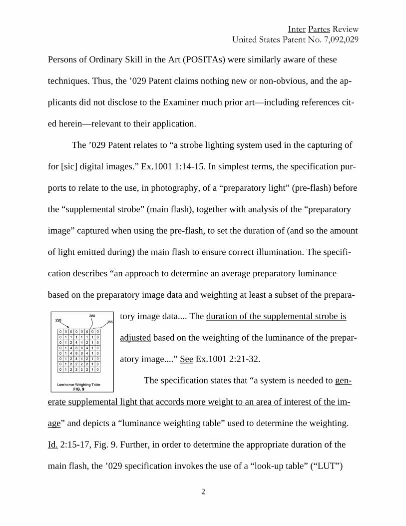
The specification states that “a system is needed to gen-
erate supplemental light that accords more weight to an area of interest of the im-
age” and depicts a “luminance weighting table” used to determine the weighting.
Id. 2:15-17, Fig. 9. Further, in order to determine the appropriate duration of the
main flash, the ’029 specification invokes the use of a “look-up table” (“LUT”)

Inter Partes Review United States Patent No. 7,092,029
3
(which is different from the luminance weighting table above) correlating “power
values” and associated “image strobe durations” in order to look up the “strobe du-
ration for the strobe by accessing the look-up table ... in accordance with a rela-
tionship between the average image weighted luminance and a target lumi-
nance . . .” Id. 9:8-11.
But there is nothing new in the Challenged Claims. The supposed “invention”
was at minimum obvious before the earliest March 24, 2000 priority date listed on
the ’029 Patent. See, e.g., Ex.1033 ¶¶ 85-86; 117-18. According to the file history,
the independent claims were allowed over the prior art on the basis of a single limi-
tation directed to a LUT.2 However, even this limitation was well known. Indeed,
Japanese Pat. App. No. H11-119288 (“Shimada”), one of two primary references
cited in this petition, read in light of a POSITA’s knowledge, renders obvious all
limitations of the Challenged Claims. And even if it is argued that some further
disclosure is required, all limitations of the Challenged Claims are certainly obvi-
ous over the combinations of Shimada, U.S. Pat. No. 6,195,127 (“Sugimoto”), and
the other art cited herein, together with the knowledge of a POSITA.
Shimada discloses a camera system and method for determining the duration
2 During prosecution, the Examiner found that Sugimoto disclosed all but one limi-
tation in each of the independent Challenged Claims. Ex.1002 at 194-99.

Inter Partes Review United States Patent No. 7,092,029
4
of the “main flash” by generating a “pre-flash,” receiving the reflected light for
that pre-flash with an “imaging element,” and performing photometry (the measur-
ing of image luminance) on only a portion of the preparatory image in order to
weight the image data. See Ex.1005 ¶ 31. Shimada further details the use of a LUT
(correlating emitted light and flash duration) to determine the main flash duration.
See id. Sugimoto, the second primary reference, discloses a camera system and
method for determining the duration of the “major light emission” (the “proper
flash duration”) by acquiring an image while generating a “preliminary light-
emission” and weighting the image data according to a luminance “weighting
amount table.” See Ex.1004 11:3-46.
As demonstrated below, every element of the Challenged Claims has been
disclosed in the prior art. The claims are nothing more than a routine and predicta-
ble combination of these well-known elements. Thus, Petitioner respectfully re-
quests that the Board find each of the Challenged Claims invalid under § 103.
II. MANDATORY NOTICES UNDER § 42.8
Samsung is the Real Party in Interest Under § 42.8(b)(1). The real par-
ties-in-interest are Petitioners Samsung Electronics Co., Ltd.; Samsung Electronics
America, Inc.; and Samsung Semiconductor, Inc.
Related Matters Under Rule § 42.8(b)(2). Imperium IP Holdings (Cay-
man), Ltd. (“Imperium”) has asserted claims 1, 6, 7, 14, and 16 of the ’029 Patent
Inter Partes Review United States Patent No. 7,092,029
5
against Petitioner in Imperium IP Holdings (Cayman) v. Samsung Electronics Co.,
et al., Case No. 4:14-cv-00371 (ALM) (E.D.T.X., filed June 9, 2014) (“EDTX”).3
Lead and Back-Up Counsel Under Rules 42.8(b)(3) and (4). Lead and
backup counsel, and service information are designated in the signature block.
III. PETITIONER HAS STANDING
A. Grounds for Standing Under § 42.104(a)
Petitioner certifies pursuant to 37 C.F.R. § 42.104(a) that the ’029 Patent is
eligible for (and that Petitioner is not barred or estopped from requesting) inter
partes review. Petitioner was served with a Complaint asserting infringement of
the ’029 Patent on or after June 9, 2014, and neither Petitioner nor any other real
party-in-interest, nor privy of Petitioner, was served with a complaint before that
date, or has initiated a civil action challenging validity of the ’029 Patent.
B. Claims and Statutory Grounds Under §§ 42.22 and 42.104(b) 3 In EDTX, Imperium sued Petitioners, along with Samsung Telecommunications
America, LLC (“STA”) and Samsung Techwin Co., LTD. and Samsung Opto-
Electronics America, Inc. (together “Techwin”). On Jan. 1, 2015, STA merged
with SEA, and ceased to exist as a separate corporate entity. See EDTX, Dkt. No.
67. The EDTX court severed Imperium’s case against Techwin, following briefing
establishing that Techwin and Petitioners are separate parties. See id, Dkt. No. 66.
Techwin is not a privy of a Petitioner or a party-in-interest in this proceeding.
Inter Partes Review United States Patent No. 7,092,029
6
Petitioner requests inter partes review of claims 1, 6, 7, 14, and 16 and as-
serts that these claims are unpatentable as follows: Ground 1: Claims 1, 6, 7, 14,
and 16 are obvious under § 103 over Shimada in view of the knowledge of a
POSITA; Ground 2: Claims 1, 6, 7, 14, and 16 are obvious under § 103 over Shi-
mada in view of Sugimoto, and U.S. Pat. No. 6,426,775 (“Kurokawa”), in further
view of the knowledge of a POSITA; Ground 3: Claims 1, 6, 7, 14, and 16 are ob-
vious under § 103 over Sugimoto in view of Shimada, in further view of the
knowledge of a POSITA; and Ground 4: Claims 1, 6, 7, 14, and 16 are obvious
under § 103 over Sugimoto in view of Kurokawa,4 in further view of the
knowledge of a POSITA. (Only Sugimoto was considered during earlier prosecu-
tion, and never in the combinations relied on herein.) §§ V.C.6 and V.D.3 below
provide claim charts specifying how the prior art renders obvious claims 1, 6, 7, 14,
and 16. In further support of the proposed grounds of rejection, the Declaration of
technical expert Kenneth Parulski is attached as Ex.1033.
4 Petitioner is not aware of any evidence suggesting Imperium could swear behind
Shimada, which is prior art under at least § 102(a). Regardless, if Imperium at-
tempts to do so, Kurokawa together with the knowledge of a POSITA similarly
discloses the limitations in the claims that: (1) are disclosed by Shimada; and (2)
applicants added to overcome the Examiner’s rejection in view of Sugimoto.
Inter Partes Review United States Patent No. 7,092,029
7
IV. SUMMARY OF THE ’029 PATENT AND ITS FIELD
A. Overview of the ’029 Patent
The ’029 Patent describes a camera system and method for adjusting the
emission of a flash in order to obtain proper image exposure. Ex.1001 Abstract;
Ex.1033 ¶¶ 51-59. The Challenged Claims are generally directed to components or
steps for adjusting image lighting by capturing a preparatory image after generat-
ing a preparatory flash for a predetermined amount of time, weighting the lumi-
nance data of the preparatory image, determining the average preparatory image
luminance, and generating a supplemental strobe duration based on the weighted
average preparatory image luminance. Id. cl. 1, 7, 14. The Challenged Claims fur-
ther require generating or accessing a LUT that associates image strobe durations
and power values. Id. The supplemental strobe duration is obtained by determining
an image power value based on the weighted average luminance of the preparatory
image and a target luminance. The LUT is then referred to, to find the strobe dura-
tion corresponding to this power value. Id. 9:18-35. The ’029 Patent states that the
adjustment of image lighting according to the alleged invention enhances the over-
all visual quality of the exposed digital image. Ex.1001 2:29-32. However, all ele-
ments of the Challenged Claims were well known before March 24, 2000, and the
claimed combination would at minimum have been obvious to a POSITA.
B. Overview of the ’029 Patent Prosecution History

Inter Partes Review United States Patent No. 7,092,029
8
The application was filed March 22, 2001, claiming priority to U.S. Prov.
App. No. 60/192,008, filed March 24, 2000. As the provisional admits, “prior art
method[s]” to adjust lighting existed wherein “a preparatory image is generated
and an average value of the preparatory image data is calculated. The duration of
the supplemental light is determined based on the average value of the image da-
ta.” Ex.1003 p. 11:32-12:2; see also Ex.1001 2:1-8. Applicants’ original claims
were directed to such a method and apparatus, but the Examiner rejected prosecu-
tion claims 1-3 and 7-9 under § 102(e) as anticipated by Sugimoto (Ex.1004) and
claims 14-16 as obvious over Sugimoto in view of U.S. Pat. 5,987,261 (“Sugaha-
ra”)5 (Ex.1008), and objected to claims 4-6, 10-13, and 17 as being dependent upon
a rejected claim. Ex.1002 at 196-200. The Examiner recognized a motivation to
combine Sugimoto and Sugahara: “Sugahara reveals that it is well known in the art
to store the time of the actual light in a LUT (See col. 4, lines 1-33). It would have
been obvious to one of ordinary skill in the art at the time the invention was made
to modify Sugimoto’s device by implementing Sugahara’s teachings in an effort to
consistently and quickly obtain an appropriate amount of light.” Id. at 198.
Applicants made an unsuccessful attempt to overcome the Examiner’s rejec-
tion by amending the claims to require a “single” preparatory image, arguing that
5 Sugahara and Shimada have similar disclosures and identical named inventors.
Inter Partes Review United States Patent No. 7,092,029
9
Sugimoto disclosed use of multiple preparatory images. Id. at 171-77, 185-87.
When this failed, Applicants further amended the claims to include a limitation di-
rected to generating (cls. 1, 7) or accessing (cl. 14) a look-up table, with the LUT
storing power values and associated image strobe durations including preparatory
power values and associated preparatory image strobe durations. Id. at 95-101;
109-10. The Examiner subsequently allowed the claims. See id. at 9.
C. Overview of the Field of the Claimed Invention
As noted, by March 24, 2000, photographers knew that they could use in-
formation generated from a pre-flash to measure the luminance level of the scene
they wanted to photograph to determine the correct emission of the main flash—
and that they could “weight” particular portions of the scene to illuminate properly
the desired part of the image. Such flash control systems had been in use since the
1990s in commercially available cameras from such major camera manufacturers
as Canon, Nikon, Kodak, and Minolta. See Ex. 1015 at 82-85; Ex.1033 ¶ 24-33. As
but one example, cameras equipped with Canon’s “Evaluative Through the Lens”
(“E-TTL”) System, such as the Canon EOS Elan II, coupled with a Canon
Speedlite 380EX flash (both available in 1995), operated by emitting a test pre-
flash to obtain an initial flash exposure reading using one metering sensors. See
Ex.1017 at 2, 10, 11, 14; Ex.1033 ¶ 43. The exposure reading was then used to
compute the main flash output. See Ex.1017 at 10 (“Immediately before the shutter
Inter Partes Review United States Patent No. 7,092,029
10
is released, the Speedlite fires a test preflash. After obtaining a flash exposure read-
ing with the preflash, the Speedlite fires the main flash accordingly….”); see also
Ex.1033 ¶¶ 32, 44-45 (Canon); ¶¶ 32, 39-42 (Nikon); ¶ 33 (Minolta).
In the late 1990s, camera manufacturers developed these established tech-
niques further as they began to shift to digital SLRs. Ex.1033 ¶¶ 34-50. One exam-
ple of such a system (introduced in 1998) was the Canon D2000/Kodak DCS520
equipped with a Canon Speedlite 380EX practicing Canon’s E-TTL system. See,
e.g., Ex.1016 at 164 (“E-TTL uses the camera’s evaluative metering sensor to ana-
lyze and compare ambient light exposure values with illumination reflected from
the subject by the preflash. This data is used to calculate and store the flash output
required for optimum exposure of the main subject....”); Ex.1033 ¶ 44. Another ex-
ample was the Nikon D1 camera with the Speedlight SB-28DX external flash, of-
fered for sale in or about 1999, which utilized Nikon’s “Digital Through the Lens”
(“D-TTL”) system. See Ex.1021 at 107 (“[This system] emits a series of nearly in-
visible preflashes (monitor preflashes) that are reflected from objects in all areas of
the frame and picked up by the camera’s five-segment TTL multi sensor.... Based
on this information, the flash output level is automatically compensated to balance
flash output with ambient light.”).
Prior to March 24, 2000, the techniques described by the Challenged Claims
were also described in many publications. Indeed, the concept of using a pre-flash

Inter Partes Review United States Patent No. 7,092,029
11
to adjust main flash emission was widespread in patent publications. One such pa-
tent is Sugahara, titled “Strobe Device” and filed Sept. 9, 1998. Ex.1008. Sugahara
describes a camera system including an image sensor, A/D converter, memory, and
flash controller that generates a fixed amount of preparatory light a plurality of
times to set an amount of actual light to be generated for the main exposure. Id. at
Abstract; Fig. 1, 2. Sugahara further describes determining the main flash duration
by referencing a LUT correlating flash duration and desired amount of emitted
light. See id. at 6:48-58. Another example is U.S. Pat. No. 5,652,929 (“Camera
Having Through-the-Lens Automatic Light Adjustment Control Device,” filed
Sept. 1, 1995), which describes “multi-light adjustment technology” using pre-
flash emission prior to a main flash as known in the prior art. See Ex.1009 1:30-55.
And, of course, similar disclosures were also in patents including Sugimoto and
Kurokawa. See Ex.1004 1:56-2:8; Ex.1010 2:25-36.
And it was not simply the general concept of using a pre-flash to determine
the main flash that was well known in the art. The other claimed components of the
’029 Patent, including the use of a weighting operation to emphasize certain por-
tions of the preliminary image and generation and use of a LUT correlating flash
durations and associated power values, were also well understood.
For example, with respect to the use of a weighting operation, the multi-
zone, pre-flash luminance metering sensor of the Canon E-TTL system was

Inter Partes Review United States Patent No. 7,092,029
12
“linked to the camera’s multiple focusing points so that the metering is weighted at
the point where focus is achieved (where the main subject is assumed to be).”
Ex.1018 at 9 (left col.); see also Ex.1015 at 49 (“Centerweighted averaging meter-
ing: The metering is weighted at the center and then averaged for the entire sce-
ne.”). The Nikon D-TTL system performed the same way. See Ex.1021 at vi
(“Center-weighted metering: The camera measures light in the entire frame, but
assigns the greatest weight to a circular area in the center of the viewfinder….”).
And, of course, Sugimoto disclosed this element. See Ex.1004 3:11-25, 6:62-67.
The generation and use of a LUT correlating flash durations and associated
power values was similarly well known. See e.g., Ex.1033 ¶¶ 28-31. As discussed
above, Sugahara discloses the use of a LUT correlating flash durations with emit-
ted light. See Ex.1008 at 6:48-58. As another example, Japanese Pat. App. No.
H01-289925 (“Nakajima”), Ex.1007, pub. Nov. 21, 1989, discloses a camera sys-
tem in which a LUT is used to determine the main strobe duration on the basis of
data obtained from a pre-flash light emission. Ex.1007 at 16-17. The LUT is com-
prised of proportions of light emission—relative to 100% emission—associated
with respective flash times. See id. at 17-18; Fig. 5. After calculating the relative
amount of emitted light needed for proper image exposure based on pre-flash im-
age luminance data, the system refers to the LUT to obtain the corresponding main
flash duration. Id. Nakajima provides that the LUT is used to compensate for the
Inter Partes Review United States Patent No. 7,092,029
13
non-linearity of light emission intensity of a flash over time. Id. 17; Fig. 4. And the
obvious point that a LUT could correlate a pre-flash of predetermined duration
with light output was similarly disclosed. See Ex.1010 5:66-6:4; Ex.1033 ¶ 101.
Another example, U.S. Pat. No. 5,257,063, titled “Flashing Controller,” issued Oct.,
1993, teaches generating a LUT prior to camera manufacturing by measuring
changes in light quantity of a strobe emission relative to strobe duration and storing
this information in memory. See Ex.1006 6:13-30; 17:18-22; Ex.1033 ¶ 31.
These examples and additional art (below §§ V.C.1-3) show that the “inven-
tion” of the Challenged Claims was widely described before the priority date. The
Challenged Claims are invalid under § 103. See generally Ex.1033 ¶¶ 85-157.
V. THERE IS A REASONABLE LIKELIHOOD THAT PETITIONER WILL PREVAIL WITH RESPECT TO AT LEAST ONE CLAIM
Petitioner submits there is at least “a reasonable likelihood that the petition-
er[] would prevail with respect to at least 1 of the claims challenged in the petition.”
§ 314(a). Indeed, these claims are obvious under the four stated Grounds.
A. Claim Construction Under § 42.104(b)(3)
Pursuant to § 42.100(b), for the purposes of this review, the claim language
is construed such that it is “given its broadest reasonable construction in light of
the specification of the patent in which it appears.” The parties in EDTX have pro-
posed constructions for disputed terms in the Challenged Claims and have agreed
to constructions for others. Ex.1032. Petitioner believes its proposed constructions

Inter Partes Review United States Patent No. 7,092,029
14
are appropriate, but does not believe that any of these constructions has any impact
or bearing on the analysis set forth in this Petition.6 See also Ex.1033 ¶ 60.
In EDTX, Samsung has argued that the term “preparatory light for a prede-
termined preparatory duration” (cls. 1, 7, 14) should be construed as “preliminary
strobe activation for a set duration.” Id. The title (“Strobe Lighting System….”)
and specification makes clear that the preparatory light is from a strobe, and is be-
ing generated by activation of the strobe. See Ex.1001 Abstract; 7:1-29; 7:46-65.
Ex.1032. Moreover, the “preparatory light” is clearly emitted as a preliminary step,
before determination of the supplemental strobe duration. See, e.g., id. at Fig. 5.
In EDTX, Samsung has also argued that two terms (“average image lumi-
nance” (cl. 6) and “weighting table that stores the luminance weighting” (cl. 16))
6 For purposes of this Petition, Petitioner interprets all other terms in accordance
with their plain and ordinary meaning under the required broadest reasonable in-
terpretation consistent with the specification of the ’029 patent in view of a POSI-
TA’s knowledge. Because the claim construction standard at the PTO is different
than litigation, see In re Am. Acad. of Sci. Tech Ctr., 367 F.3d 1359, 1364, 1369
(Fed. Cir. 2004); MPEP § 2111, Petitioner reserves the right to argue in litigation
constructions for any term as appropriate to that proceeding.
Inter Partes Review United States Patent No. 7,092,029
15
are indefinite for lack of antecedent basis.7 See Ex.1032 at 21. Imperium has ar-
gued these terms are not indefinite and should be given their plain and ordinary
meaning, and in the alternative should be construed as “average luminance of the
preparatory image” and “luminance weighting table that stores the luminance
weighting” respectively. Id. As Imperium has taken the position that the phrases
are not indefinite and that its alternative constructions are correct even under the
narrower standard applicable in litigation, see Am. Acad. of Sci. Tech at 1369, it
must agree and is in no position to dispute that the broadest reasonable interpreta-
tion applicable for review purposes must at least include its constructions in
EDTX. For review purposes only, to the extent the Board believes construction is
possible, and to allow an analysis of the ’029 Patent under § 103, Petitioner sub-
mits that the constructions proposed by Imperium in EDTX may be adopted here.
B. Level of Ordinary Skill in the Art and State of the Art
Petitioner submits that the applicable person of ordinary skill in the art
would have a minimum of: (1) a Bachelor’s degree in Electrical Engineering,
Physics, or related field; and (2) 4 or more years of industry experience engineer-
ing or designing imaging devices. With respect to (2), a person of ordinary skill 7 Samsung initially argued that a third term, “generating a supplemental strobe du-
ration” (cls. 1, 7), was indefinite, but has agreed to accept Imperium’s proposed
“plain and ordinary meaning” reading.
Inter Partes Review United States Patent No. 7,092,029
16
may have equivalent industry experience, such as research or laboratory experience,
see Ex.1033 ¶ 20. This person would also be acquainted with the basic concepts of
amateur photography.
C. Grounds 1 and 2
1. Overview of Shimada
Shimada (“Strobe Device,” filed Oct. 9, 1997, pub. April 30, 1999) is prior
art under at least § 102(a). Ex.1005; Ex.1033 ¶¶ 66-72. Shimada discloses a camera
system that creates a preliminary exposure of a photographic subject using a pre-
flash of the strobe prior to the main photographic exposure. See Ex.1005 ¶ 12, cl.
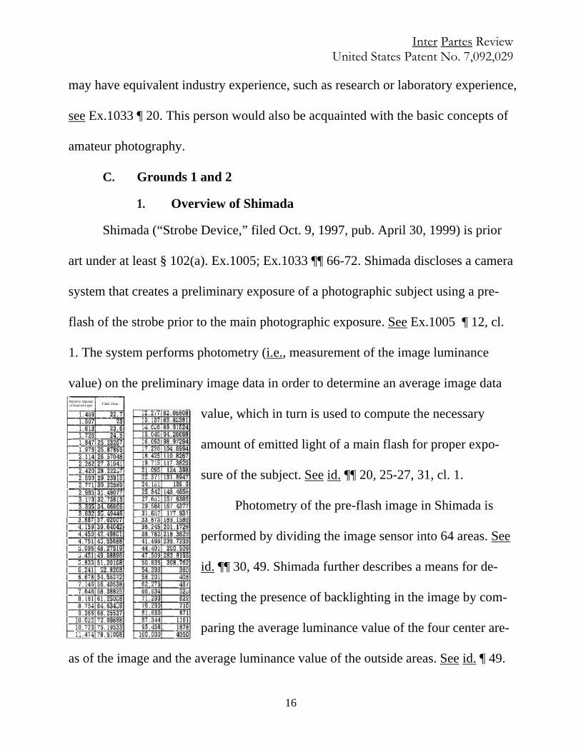
1. The system performs photometry (i.e., measurement of the image luminance
value) on the preliminary image data in order to determine an average image data
value, which in turn is used to compute the necessary
amount of emitted light of a main flash for proper expo-
sure of the subject. See id. ¶¶ 20, 25-27, 31, cl. 1.
Photometry of the pre-flash image in Shimada is
performed by dividing the image sensor into 64 areas. See
id. ¶¶ 30, 49. Shimada further describes a means for de-
tecting the presence of backlighting in the image by com-
paring the average luminance value of the four center are-
as of the image and the average luminance value of the outside areas. See id. ¶ 49.
Inter Partes Review United States Patent No. 7,092,029
17
Shimada teaches performing photometry for only the central four areas if a back-
light is detected; in a non-backlit state, a wider area is subject to photometry to de-
termine the average image data value. See id. ¶ 50.
Shimada further teaches calculating a relative amount of light, S, needed for
the main flash for proper exposure based on the pre-flash image data value. See id.
¶¶ 37-45. Shimada then teaches the use of a LUT comprised of empirically-
determined relative light values associated with flash time durations in order to
identify the main flash duration corresponding to that desired amount of relative
light. See id. ¶¶ 7, 31-36; Table 1.
Shimada recognizes that its LUT is advantageous because it accounts for the
non-linear relationship between flash intensity and flash duration. See id. ¶¶ 6, 33-
34; Fig. 3. Shimada further recognizes that its LUT, arranged in a geometric se-
quence, is advantageous over prior art LUTs arranged in arithmetic sequence be-
cause, in arithmetic sequences, the precision required for controlling the amount of
light becomes unnecessarily high as the relative amount of emitted light becomes
larger. See id. ¶¶ 35-36. (These advantages are similarly disclosed by the ‘029 pa-
tentees when discussing the LUT of the ’029 Patent. See Ex.1001 11:1-19.)
2. Overview of Sugimoto
Sugimoto (“Digital Camera, Having a Flash Unit, Which Determines Proper
Flash Duration Through an Assessment of Image Luminance and, Where Needed,

Inter Partes Review United States Patent No. 7,092,029
18
a Preliminary Flash Emission,” filed July 16, 1997, issued Feb. 27, 2001) is prior
art under at least § 102(e). See Ex.1004; Ex.1033 ¶¶ 73-78. The stated object of
Sugimoto is to provide “a digital camera capable of precisely calculating a major
light-emission element of a flash lamp.” Ex.1004 1:49-52. Sugimoto discloses a
digital camera system that first exposes preliminary images without light-emission
of the flash lamp, and then (if the system determines that a suitable exposure can-
not be obtained at a minimum shutter speed) exposes second preliminary images
with a preliminary light emission. See id. 9:53-10:5; Fig. 7, 8. The system calcu-
lates the major light-emission amount (i.e., main flash) by evaluating the lumi-
nance of these preliminary images. See id. 2:9. Luminance evaluation values of
preliminary images are determined by obtaining luminance data from pixel blocks
of the image sensor. See id. 5:58-6:16. This data is then input into a weighting op-
eration according to a weighting table. See id. 6:17-31; Fig. 5, 6. The weighting ta-
ble is divided into 265 areas, each area corresponding to a set of pixel blocks from
the image sensor and having a weighting value. See id. 6:32-43; Fig. 5, 6. The lu-
minance data of the entire image is weighted, integrated, and normalized to calcu-
late a luminance evaluation value. Id. 7:29-40. By applying the weighting opera-
tion to the luminance data, it is possible to emphasize the luminance level of a por-
tion of the image, such as the center portion, when determining the luminance
evaluation value. Id. 6:54-67. In the case of a preliminary exposure with a prelimi-

Inter Partes Review United States Patent No. 7,092,029
19
nary light emission, the luminance evaluation value, Ys, is subtracted from a target
evaluation value to determine a luminance shortage value, U. This value is divided
by Ys and multiplied by the preliminary light emission amount, P, in order to cal-
culate the major light-emission amount, Q, for the main exposure. Id. 10:45-53;
10:62-11:2, 11:10-27.
3. Overview of Kurokawa
Kurokawa, “Image Pickup Apparatus with Distance Measurement Depend-
ent on Object Lighting Condition,” filed Sept. 16, 1996 and is-
sued July 30, 2002, is prior art to the ’029 Patent under at least
§ 102(e). See Ex.1033 ¶¶ 79-84. Kurokawa teaches a camera
system that utilizes a fixed (i.e., predetermined) preliminary light
emission along with a LUT in order to determine the optimum
flash time for the main exposure. See Ex.1010 2:10-36, 5:47-6:4.
The system takes luminance and distance measurements of the
subject to determine whether a flash emission is necessary. If it is, the camera
emits a preliminary light for a fixed duration to obtain a fixed quantity of emitted
light, and exposes a preliminary image. The luminance of the image exposed by
Kurokawa’s solid-state image sensor is determined and used to generate a guide
number corresponding to a suitable exposure level of the main image. See id. 5:47-
65; see also 2:10-36. Subsequently, the system refers to a LUT comprised of guide

Inter Partes Review United States Patent No. 7,092,029
20
numbers and flash durations. Id. 5:66-6:12; Fig. 3. The main flash duration corre-
sponding to the calculated guide number is selected from this table, and the main
image is exposed at this flash duration. Id.
4. Motivation to Combine Shimada with Sugimoto
A POSITA would have been motivated and found it obvious to implement
Sugimoto’s teachings of using luminance weightings in adjusting flash operation in
implementing Shimada’s camera system. See, e.g., Ex.1033 ¶¶ 87-93; 105-07; 110;
116. As an initial matter, Shimada and Sugimoto have overlapping disclosures and
similar purposes. The explicit teachings of both relate to improved methods of
flash photography, and in particular involve calculating the duration of a main
flash by using a pre-flash, measuring the luminance from a pre-flash, and deter-
mining the main flash duration based on the luminance of the preparatory image.
See, e.g., Ex.1005 Abstract; Ex.1004 1:56-2:8, 11:13-46. These teachings confirm
a motivation to combine.8 See Ex.1033 ¶¶ 87, 88. In particular, Shimada presents a 8 A closely related motivation to combine based on explicit teachings and similar
purpose was observed by the Examiner, who during prosecution of the ’029 appli-
cation determined it would have been obvious to combine Sugimoto with Sugahara
(which has a similar disclosure to Shimada and shares identical named patentees),
noting it would have been obvious “to modify Sugimoto’s device by implementing
Sugahara’s teachings in an effort to consistently and quickly obtain an appropriate
Inter Partes Review United States Patent No. 7,092,029
21
problem (accurately determining the proper duration and output of the main flash
when there is backlighting), and provides an incomplete solution (fully weighting
or considering the pre-flash data only from the center portions of the image but ig-
noring the remainder of the image). See id.¶ 89. Sugimoto provides a more advan-
tageous solution (partially weighting the center or any other area of interest of the
image, and also even when there is backlighting, taking into consideration the lu-
minance of other areas of the image that are not in the center). See id. ¶¶ 90-91.
Shimada teaches that (1) backlighting represents a problem because using
luminance data equally from all portions of a backlit image results in underexpo-
sure, Ex.1005 ¶ 51, and (2) this problem can be addressed by using luminance data
from (i.e., performing photometry on) only a subset of the area of the image (e.g.,
the center 4 out of 64 portions of the image), id. ¶¶ 50-56. However, Shimada’s so-
lution to the backlighting problem uses data from only the image center (i.e.,
weighting the center at 100% and everything else at 0%). See Ex.1033 ¶ 87, 89.
Sugimoto provides an advantageous method in which, instead of entirely discount-
ing outer portions of the image and relying only on luminance data from the center,
the system provides for a set weighting to be applied to additional portions of the
image. See, e.g., Ex.1004 6:62-67 (“By subjecting the weighting operation to the
amount of light.” Ex.1002 at 198.
Inter Partes Review United States Patent No. 7,092,029
22
luminance data in accordance with the weighting amount data K, it is possible to
perform center emphasis photometry that a luminance level of the center of the
screen is considered to be the most important and the luminance level of a sur-
rounding area is also sufficiently considered.”); see also id. 7:1-21; 11:66-12:7;
Ex.1033 ¶¶ 91, 92. Moreover, Sugimoto’s luminance weighting table accounts for
the possibility that the desired area of interest may not be in the center of the im-
age, providing additional advantageous flexibility. See, e.g., Ex.1004:7:1-21; see
also Ex.1033 ¶ 92.
While problems solved by Shimada and Sugimoto are similar, Sugimoto’s
solution to the problem of backlighting has advantages over Shimada’s that a
POSITA would recognize, and thus a POSITA would have been motivated to use
the advantageous teachings of Sugimoto in implementing the method of weighting
image luminances in Shimada. See Ex.1033 ¶¶ 92-93.
5. Motivation to Combine Shimada with Kurokawa
A POSITA would also have been motivated and found it obvious to imple-
ment Kurokawa’s explicit teaching of using a pre-flash of a predetermined duration
in the camera system of Shimada. See Ex.1033 ¶¶ 94-100. Again, Shimada and
Kurokawa have overlapping disclosures and similar purpose. Both explicitly relate
to improved methods of flash photography, and in particular involve calculating
the duration of a main flash by using a pre-flash, measuring the measuring the lu-

Inter Partes Review United States Patent No. 7,092,029
23
minance from a pre-flash, determining the main flash duration based on the aver-
age luminance of the preparatory image, and using a LUT correlating flash output
and flash duration, see, e.g., Ex.1005 Abstract, ¶¶ 31-33; Ex.1010 Abstract, 5:47-
6:4, confirming a motivation to combine the two references. See Ex.1033 ¶¶ 94-95.
More specifically, a POSITA would have been motivated to implement Ku-
rokawa’s advantageous teaching of a predetermined preparatory flash duration in
the camera system of Shimada for several reasons. See id. First, Shimada teaches
that a main flash can be controlled with high precision by a system that uses calcu-
lations based on the intensity and reflected value of a pre-flash. See, e.g., Ex.1005
[Solution]; ¶¶ 7, 12, 26-27. Second, Shimada teaches that the relationship between
flash intensity and flash time is “a non-linear relationship,” such that “it is not pos-
sible to determine the relationship between the flash time and the amount of emit-
ted light in a functional manner,” so that the camera system of Shimada uses the
LUT correlating flash output and flash time to calculate the main flash. See, e.g.,
id. ¶¶ 6, 33. And third, Shimada teaches that the pre-flash is set for a shorter dura-
tion than is the main flash. See, e.g., id. ¶¶ 59-63, Fig. 5. In order to determine the
duration (which equates to the output) of the main flash using the LUT in Shimada,
it is necessary to know the output of the pre-flash. See Ex.1033 ¶ 98. As Shimada’s
teachings regarding the use of a LUT, see Ex.1005 ¶¶ 6, 33, make clear, and as a
POSITA would have known, see id., one method of setting the amount of light of a
Inter Partes Review United States Patent No. 7,092,029
24
flash is to adjust the duration of the flash.
Kurokawa provides an advantageous means of setting the output of the pre-
flash by setting its duration, which Kurokawa teaches has particular benefits. See,
e.g., Ex.1010 7:28-30; 7:21-23; see also Ex.1033 ¶¶ 97, 102-03. In particular, Ku-
rokawa teaches that using a pre-flash of predetermined duration is advantageous
(i.e., “a great advantage in respect to the cost of manufacture and development of
products,” Ex.1010 5:35-47; 7:19-45), because it means that there is a need for on-
ly one type of LUT (i.e., a table correlating flash duration and flash output), and
the system “obviates the necessity of any additional detecting circuit ... and any ta-
ble or any related formula for deciding the light emission time according to the re-
maining charging voltage,” id. 7:39-43. Moreover, Kurokawa teaches that it is ad-
vantageous to use a predetermined pre-flash duration in order to provide a fixed
amount of preliminary light that is smaller than the amount at full flash, such that
the discharge voltage is minimized and the remaining charging voltage of the flash
is kept constant after the pre-flash, in order to obviate the need for a camera with
more than one look-up table or a voltage detecting circuit. This results in “a great
advantage in respect to the cost of manufacture and development of products.” See
id. 7:43-44; see also Ex.1033 ¶ 97.
Shimada similarly discloses setting a preliminary light emission amount
smaller than the amount of emission at main flash, but does not explicitly describe

Inter Partes Review United States Patent No. 7,092,029
25
the means for accomplishing this emission. See also Ex.1033 ¶ 98. When imple-
menting the pre-flash step of Shimada, a POSITA would have been motivated to
employ Kurokawa’s beneficial teaching of using a predetermined pre-flash dura-
tion to obtain a fixed amount of preparatory light in order to obtain the advantages
described above of using a predetermined pre-flash duration that results in a small-
er emission than the amount of light at full flash. See id. ¶¶ 98-99.
6. Grounds 1 and 2 Claim Chart for Claims 1, 6, 7, 14, and 16
cl. 1 Prior Art 1. A method of ad-justing image lighting, the method compris-ing:
Shimada discloses a method of adjusting image lighting. See, e.g., Ex.1005 Fig. 2; ¶ 31 (“The method for computing the amount of emit-ted light of a main flash in the Step S7 will be explained here …. [T]he method described below is used to determine a relative amount of emit-ted light on the basis of an average value VM for image data corre-sponding to a proper exposure, and an average value VP for image data obtained by performing a pre-flash for an arbitrary subject, and in addi-tion, a LUT (Table 1) representing the relationship between the relative amount of emitted light and the flash time is stored beforehand in stor-age means as a file, and the flash time of a main flash is determined by referring thereto ….”; see also id. ¶ 12; Ex.1033 ¶ 101, pp. 120-22.
[1-1] generat-ing a prepara-tory light for a prede-termined prepara-tory du-ration;
Shimada teaches generating a preparatory light (e.g., pre-flash) for a predetermined preparatory duration (e.g., “a prescribed amount of emitted light”). See, e.g., Ex.1005 ¶ 1 (“The present invention relates to a strobe device, and in particular, to a strobe device for performing a pre-flash for radiating an auxiliary light toward a subject prior to taking
a photograph, and setting an amount of light for a main flash.”); ¶ 7 (“That is, the relationship be-tween a prescribed amount of emitted light (a rela-tive amount of emitted light) and a flash time is tabulated on the basis of a full flash (100% flash), and the flash time of the strobe is controlled by re-
ferring to the table for a flash time that corresponds to the relative amount of emitted light necessary to obtain the proper exposure com-

Inter Partes Review United States Patent No. 7,092,029
26
cl. 1 Prior Art puted on the basis of a pre-flash.”); Fig. 59; see also id. ¶¶ 2, 34, 38, 42-45, 63; Ex.1033 ¶ 101, pp. 122-25.
Kurokawa teaches generating (e.g., “making”) a preparatory light (e.g., “first light emission”) for a predetermined preparatory dura-tion (e.g., “predetermined period of time”).10 See, e.g., Ex.1010 Ab-stract (“[T]he control part … causes the light emission part to emit light for a predetermined period of time….”); 4:62-5:17 (“[A] prelimi-nary exposure is performed by making a first light emission for a prede-termined period of time….”); 9:28-45; see also id. 2:10-37; 7:19-23; 10:56-64; cls. 1, 2; Ex.1033 ¶ 102, pp. 125-33.
[1-2] capturing a prepar-atory image while generat-ing the
Shimada teaches capturing a preparatory image (e.g. exposure of the CCD performed under pre-flash) while generating the preparato-ry light (e.g., pre-flash), wherein the preparatory image is repre-sented by preparatory image data (e.g., “image data from pre-flash”; “a preflash is performed”; “image data is stored in the memory 7”). See, e.g., Ex.1005 Fig. 2.; ¶ 12 (“A first strobe device of the present invention comprises: pre-flash radiating means for performing a pre-flash . . .; an imaging element for receiving a pre-flash by the pre-flash
9 All red text and markings are added. It would have been at minimum obvious to a
POSITA, who would recognize that flashes have known outputs, to generate a “set”
amount of light in the pre-flash as described at least in Ex.1005 Fig. 5 ¶ 63, by
generating the pre-flash for a predetermined duration. See Ex.1033 ¶ 101, p. 122.
10 To the extent it is argued that further disclosure is required to render obvious us-
ing a predetermined preparatory duration for the pre-flash, a POSITA would have
been motivated to employ Kurokawa’s express teaching of a predetermined pre-
paratory duration in the camera system of Shimada. See § V.C.5, supra; see also
Ex.1033 ¶¶ 94-100, pp. 125-33.
Inter Partes Review United States Patent No. 7,092,029
27
cl. 1 Prior Art prepara-tory light, wherein the pre-paratory image is repre-sented by pre-paratory image data;
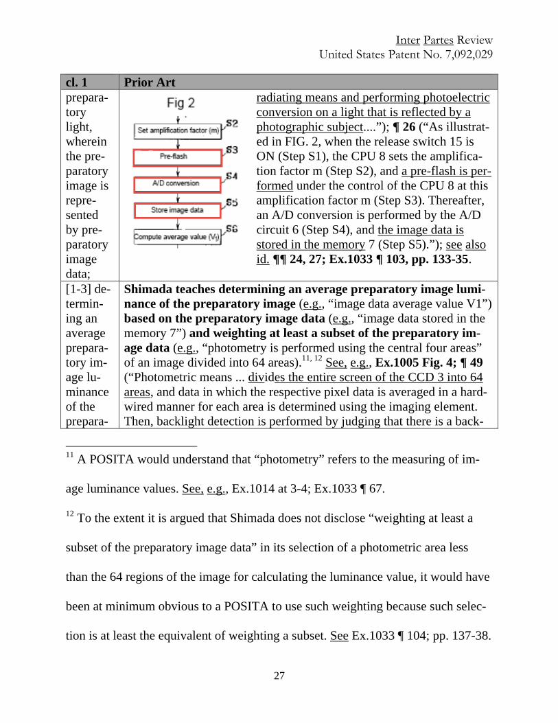
radiating means and performing photoelectric conversion on a light that is reflected by a photographic subject....”); ¶ 26 (“As illustrat-ed in FIG. 2, when the release switch 15 is ON (Step S1), the CPU 8 sets the amplifica-tion factor m (Step S2), and a pre-flash is per-formed under the control of the CPU 8 at this amplification factor m (Step S3). Thereafter, an A/D conversion is performed by the A/D circuit 6 (Step S4), and the image data is stored in the memory 7 (Step S5).”); see also id. ¶¶ 24, 27; Ex.1033 ¶ 103, pp. 133-35.
[1-3] de-termin-ing an average prepara-tory im-age lu-minance of the prepara-
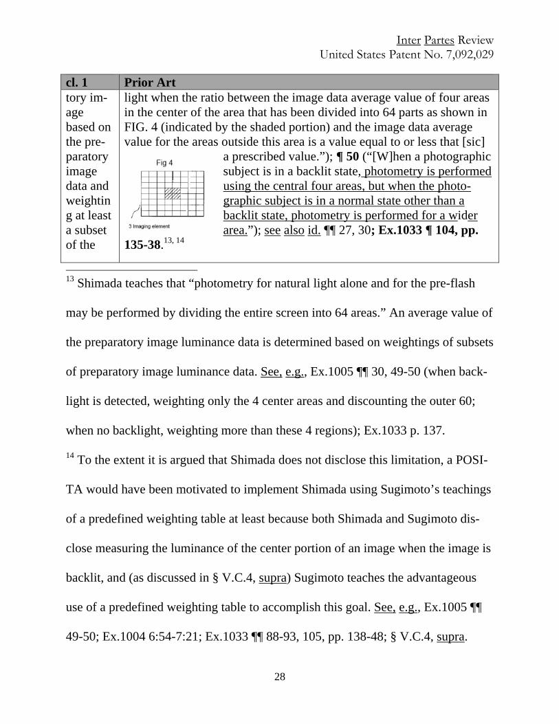
Shimada teaches determining an average preparatory image lumi-nance of the preparatory image (e.g., “image data average value V1”) based on the preparatory image data (e.g., “image data stored in the memory 7”) and weighting at least a subset of the preparatory im-age data (e.g., “photometry is performed using the central four areas” of an image divided into 64 areas).11, 12 See, e.g., Ex.1005 Fig. 4; ¶ 49 (“Photometric means ... divides the entire screen of the CCD 3 into 64 areas, and data in which the respective pixel data is averaged in a hard-wired manner for each area is determined using the imaging element. Then, backlight detection is performed by judging that there is a back-
11 A POSITA would understand that “photometry” refers to the measuring of im-
age luminance values. See, e.g., Ex.1014 at 3-4; Ex.1033 ¶ 67.
12 To the extent it is argued that Shimada does not disclose “weighting at least a
subset of the preparatory image data” in its selection of a photometric area less
than the 64 regions of the image for calculating the luminance value, it would have
been at minimum obvious to a POSITA to use such weighting because such selec-
tion is at least the equivalent of weighting a subset. See Ex.1033 ¶ 104; pp. 137-38.
Inter Partes Review United States Patent No. 7,092,029
28
cl. 1 Prior Art tory im-age based on the pre-paratory image data and weighting at least a subset of the
light when the ratio between the image data average value of four areas in the center of the area that has been divided into 64 parts as shown in FIG. 4 (indicated by the shaded portion) and the image data average value for the areas outside this area is a value equal to or less that [sic]
a prescribed value.”); ¶ 50 (“[W]hen a photographic subject is in a backlit state, photometry is performed using the central four areas, but when the photo-graphic subject is in a normal state other than a backlit state, photometry is performed for a wider area.”); see also id. ¶¶ 27, 30; Ex.1033 ¶ 104, pp.
135-38.13, 14
13 Shimada teaches that “photometry for natural light alone and for the pre-flash
may be performed by dividing the entire screen into 64 areas.” An average value of
the preparatory image luminance data is determined based on weightings of subsets
of preparatory image luminance data. See, e.g., Ex.1005 ¶¶ 30, 49-50 (when back-
light is detected, weighting only the 4 center areas and discounting the outer 60;
when no backlight, weighting more than these 4 regions); Ex.1033 p. 137.
14 To the extent it is argued that Shimada does not disclose this limitation, a POSI-
TA would have been motivated to implement Shimada using Sugimoto’s teachings
of a predefined weighting table at least because both Shimada and Sugimoto dis-
close measuring the luminance of the center portion of an image when the image is
backlit, and (as discussed in § V.C.4, supra) Sugimoto teaches the advantageous
use of a predefined weighting table to accomplish this goal. See, e.g., Ex.1005 ¶¶
49-50; Ex.1004 6:54-7:21; Ex.1033 ¶¶ 88-93, 105, pp. 138-48; § V.C.4, supra.
Inter Partes Review United States Patent No. 7,092,029
29
cl. 1 Prior Art prepara-tory im-age data;
Sugimoto teaches determining an average preparatory image lumi-nance of the preparatory image (e.g., “luminance evaluation value Vy in the preliminary light emission” and/or “preliminary light-emission luminance evaluation value Ys”) based on the preparatory image data (e.g., image data from the CCD imager exposed during the preliminary light-emission) and weighting at least a subset of the preparatory image data (e.g., luminance data Dy weighed by weighting circuit 22 in annotated Fig. 1 and luminance weighting tables in Figs. 5, 6).15 See, e.g., Ex.1004 Fig. 1, 5, 6; 9:1-25 (“[T]he image
15 Preliminary light-emission luminance evaluation value Ys is an average prepara-
tory image luminance because Ys is the “luminance evaluation value Vy in the pre-
liminary light-emission,” and Vy is the integration of the weighted values divided
by the total sum of the weighting amount data—that is, a weighted average of Dy.
Ex.1004 11:9-13. Specifically, Sugimoto teaches that weighting circuit 22 applies
either a first or second weighting table with luminance weightings (weighting
amount data K) to Dy. See, e.g., id. Figs. 1, 5, and 6 (disclosing weighting tables as
elements 28 and 30). The integrator 24 integrates (sums) the output of the
weighting circuit 22 and the calculator 26 divides the output of the integrator 24 by
the sum of the weighting amount data. See, e.g., id. 7:29-40; Fig. 1. Therefore, the
preliminary light-emission luminance evaluation value Ys is “based on the pre-
paratory image data and weighting at least a subset of the preparatory image data”
(preliminary light-emission luminance data Dy). Accordingly, Sugimoto’s deriva-
tion of preliminary light-emission luminance evaluation value Ys discloses this
Inter Partes Review United States Patent No. 7,092,029
30
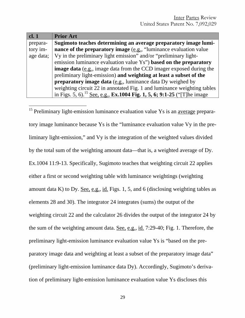
cl. 1 Prior Art data generated by this exposure is written into the RAM 16, thereafter, the calculator 20 calculates the luminance data and the color difference data on the basis of the image data. Only the luminance data Dy is sub-jected to the weighting operation in the weighting circuit 22 in accord-ance with the weighting amount data K stored in the first weighting amount table 28, whereby the luminance data, having attached im-portance to the center of the screen, is obtained. The integrator 24 digi-tally integrates the luminance data equal to 1 frame, and the accumula-tor 26 divides the integrated value by the total sum of the weighting amount data, whereby the luminance evaluation value Vy is calculated attaching importance to the center of the screen.... ”); 6:17-7:21; 7:29-41; 3:11-25; 11:3-13; 13:44-58; Ex.1033 ¶ 105; pp. 138-48.
[1-4] generat-ing a supple-mental strobe duration based on the aver-age pre-paratory
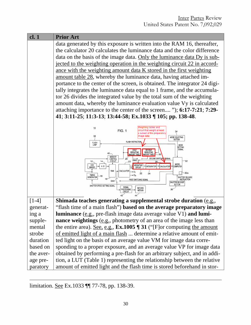
Shimada teaches generating a supplemental strobe duration (e.g., “flash time of a main flash”) based on the average preparatory image luminance (e.g., pre-flash image data average value V1) and lumi-nance weightings (e.g., photometry of an area of the image less than the entire area). See, e.g., Ex.1005 ¶ 31 (“[F]or computing the amount of emitted light of a main flash ... determine a relative amount of emit-ted light on the basis of an average value VM for image data corre-sponding to a proper exposure, and an average value VP for image data obtained by performing a pre-flash for an arbitrary subject, and in addi-tion, a LUT (Table 1) representing the relationship between the relative amount of emitted light and the flash time is stored beforehand in stor-
limitation. See Ex.1033 ¶¶ 77-78, pp. 138-39.
Inter Partes Review United States Patent No. 7,092,029
31
cl. 1 Prior Art image lumi-nance and lu-minance weight-ings;
age means as a file, and the flash time of a main flash is determined by referring thereto to decide the actual amount of emitted light.”); ¶¶ 49, 50, 55; see also id. Table 1; Fig. 4; ¶¶ 6-7, 32; 37-45; Ex.1033 ¶ 106, pp. 148-52.16
Sugimoto17 teaches generating a supplemental strobe duration (e.g., the duration associated with major light-emission amount Q) based on the average preparatory image luminance (e.g., preliminary light-emission luminance evaluation value Ys) and luminance weightings
16 Shimada discloses generating a main flash duration (“flash time”) based on aver-
age values of the preparatory image luminance data and luminance weightings (as
described in n.13, supra). Specifically, the duration is selected from the times tabu-
lated in the right column of Table 1 by calculating the relative amount of emitted
light, S, based on the pre-flash image data average value VP and an image data av-
erage value VM corresponding to proper exposure. See, e.g., Ex.1005 Table 1; ¶¶
31-32, 37-45; see also ¶¶ 49-56; element 1-3; Ex.1033 ¶ 106, p. 148.
17 To the extent it is argued that Shimada does not disclose this limitation, for the
reasons discussed, see § V.C.4, supra, a POSITA would at minimum have been
motivated to implement Shimada’s camera system using Sugimoto’s teachings of
the use of luminance weighting. See Ex.1033 ¶¶ 87-93, 107, pp. 156-59.
Inter Partes Review United States Patent No. 7,092,029
32
cl. 1 Prior Art (e.g., weighting amount data K).18 See, e.g., Ex.1004 10:45-11:46 (“[T]he microcomputer 32 regards the luminance evaluation value Vy in the preliminary light-emission as a preliminary light-emission lumi-nance evaluation value Ys in a step S43. Thereafter, the microcomputer 32 calculates a major light-emission amount Q of the flash lamp 38 in the major light-emission in accordance with a following equation in a step S45. Q=(U/Ys)xP. In this equation, by dividing the shortage amount U of the luminance by the preliminary light-emission lumi-nance evaluation value Ys, how many times of the evaluation value ob-tained by one preliminary light-emission is necessary to supplement the shortage amount is calculated, and furthermore, by multiplying the light-emission amount in the preliminary light-emission with a magni-fication calculated, the major light-emission amount Q is finally ob-tained.... [T]he microcomputer 32 outputs the flash instruction for the major light-emission to the flash lamp 38, and the flash lamp 38 emits the light during the exposure of the CCD imager 12 by a period equal to the major light-emission amount Q in a step S51.”); see also id. 7:29-40; 13:44-58; Ex.1033 ¶ 107, pp. 133-59.
[1-5] and generat-ing a look-up table storing associat-
Shimada teaches generating (e.g., determining “via experimentation beforehand” and storing in memory) a look-up table (e.g., look up ta-ble LUT) storing associated image strobe durations (e.g., flash time) and power values (e.g., relative amount of emitted light S) including a preparatory image strobe duration (e.g., flash time for pre-flash) and associated preparatory power value (e.g., relative amount of emitted light for pre-flash).19, 20, 21 See, e.g., Ex.1005 Table 1 (¶ 32); ¶ 6
18 Sugimoto’s microcomputer determines the strobe duration needed to generate
the proper amount of light (Q), which is based on the average preparatory image
luminance (Ys) and luminance weightings (K). See, e.g., id. 11:14-46; see also el-
ement 1-3. Duration is thus based on Ys and K. See Ex.1033 ¶ 78, p. 153.
19 A POSITA would have understood that the existence of a LUT necessarily, and
thus inherently, requires generation of that LUT. Ex.1033 ¶ 108, pp. 160-61. To the
Inter Partes Review United States Patent No. 7,092,029
33
cl. 1 Prior Art ed image strobe durations and power
(“[T]echnical means for using a table in which the relationship between the flash time and the amount of emitted light has been determined via experimentation beforehand, and obtaining the desired amount of emit-ted light by controlling the flash time has been proposed.”); ¶ 34 (“[T]he flash time of the strobe is controlled by storing beforehand as a
extent it is argued any further disclosure is required, it would at minimum have
been obvious to a POSITA in light of the use of a LUT in Shimada to generate
such a LUT. Ex.1033 ¶ 108, pp. 160-61.
20 To the extent it is argued that Shimada does not disclose a LUT containing a
preparatory image strobe duration and associated preparatory power value, it
would at minimum have been obvious to a POSITA in light of Shimada’s disclo-
sure of fixed factor K and a LUT storing paired values for amount of emitted light
and flash time, both stored in memory, and a “set” amount of light at pre-flash, to
include the preparatory power value and preparatory duration in the LUT. See
Ex.1033 ¶ 108, p. 161; Ex.1005 ¶¶ 32-35 42-45.
21 Specifically, Shimada discloses a LUT that is determined experimentally and
stored in memory. See, e.g., Ex.1005 ¶¶ 6, 32, 34. The LUT stores, as entries,
power values (e.g., S) and associated image strobe durations (e.g., flash times) re-
quired for obtaining the power value. See, e.g., id. ¶¶ 34, 44, 45. The relative
amount of emitted light S is expressed as a percentage of the full flash light emis-
sion. See, e.g., id.; ¶¶ 7, 34; Ex.1033 ¶¶ 69, 70, 109, pp. 160-61.

Inter Partes Review United States Patent No. 7,092,029
34
cl. 1 Prior Art values including a prepar-atory image strobe duration and as-sociated prepara-tory power value.
file in storage means a LUT which represents the relationship between a relative amount of emitted light … and a flash time required for ob-taining the prescribed amount of emitted light, and referring to the LUT for a flash time that corresponds to the relative amount of emitted light required to obtain the proper exposure computed on the basis of a pre-flash. Actually, the amount of emitted light in a full flash at main flash time is regarded as 100%, and the relative amount of emitted light is expressed as a percentage thereof.”); ¶ 39 (“Alternatively, the LUT il-lustrated in Table 1 is a table that shows the relationship between a rela-tive amount of emitted light based on a full flash, and a flash time.”); ¶¶ 8, 42; see also id. ¶¶ 4-5, 7, 37-38, 43-45; Ex.1033 ¶ 108, pp. 160-64.
cl. 6 Prior Art 6. The method of claim 1 further comprising:
See claim 1.
accessing the look-up table based on the aver-age image luminance.
Shimada teaches accessing the look-up table (e.g., look up table LUT) based on the average image lumi-nance (e.g., VP). See, e.g., element 1-522; Ex.1005 Ta-ble 1; ¶¶ 6-7; 32; 41; 45; Ex.1033 ¶ 109, pp. 165-66.
cl. 7 Prior Art 7. A memory hav-ing machine reada-ble instructions for execution by a pro-cessor to adjust im-
Shimada discloses a memory (e.g., ROM 16) having ma-chine readable instructions for execution by a processor (e.g., CPU 8) to adjust image lighting. See, e.g., element 1, above; see also Ex.1005 Fig. 1, ¶ 20; Ex.1033 ¶ 110, pp. 166-68.23
22 The LUT is based on the relative amount of emitted light S which is calculated
using the average preparatory image luminance VP. See, e.g., Ex.1005 ¶¶ 42-45;
Ex.1033 p. 165.
23 As Shimada teaches use of a processor to calculate the main flash using the pre-
paratory image captured after pre-flash, Shimada necessarily, and thus inherently

Inter Partes Review United States Patent No. 7,092,029
35
cl. 7 Prior Art age lighting, the memory compris-ing:
[7-1] a first set of machine readable instructions for ac-quiring a preparato-ry image while generating a pre-paratory light for a
Shimada discloses machine readable instructions24 for acquiring a preparatory image (e.g. exposure of the CCD performed under pre-flash) while generating the prepara-tory light (e.g., pre-flash), for a predetermined preparato-ry duration. See, e.g., elements 1-1 and 1-2, above; Ex.1033 ¶ 110, pp. 168-69.
discloses machine readable instructions (including instructions for performing the
task of adjusting image lighting, as well as all other elements of Claim 7) for exe-
cution by the processor. See, e.g., element 1, above; see also Ex.1005 Fig. 1. In-
deed, the only way for a processor to perform the claimed functionality would be
using such instructions (code). Alternatively, using such instructions would at min-
imum have been obvious to a POSITA. See Ex.1033 ¶ 110, pp. 166-67.
24 See n.23, supra (re: machine-readable instructions).
Inter Partes Review United States Patent No. 7,092,029
36
cl. 7 Prior Art predetermined pre-paratory duration;
Kurokawa teaches machine readable instructions25 for acquiring a preparatory image (e.g., exposure of the solid-state image sensor) while generating (e.g., “making”) a preparatory light (e.g., “first light emission”) for a prede-termined preparatory duration (e.g., “predetermined peri-od of time”). See, e.g., elements 1-1 and 1-2, above; Ex.1033 ¶ 110, pp. 169-73.26
[7-2] a second set of machine reada-ble instructions for determining an av-erage preparatory image luminance based on preparato-ry image data asso-ciated with the pre-paratory image and weighting at least a subset of the pre-paratory image da-ta;
Shimada discloses machine readable instructions for de-termining an average preparatory image luminance (e.g., “image data average value V1” and/or “image data average value VP obtained as a result of the above-described pre-flash that was actually performed”) based on preparatory image data associated with the preparatory image (e.g. exposure of the CCD performed under pre-flash) and weighting at least a subset of the preparatory image data (e.g., “photometry is performed using the central four areas” of an image divided into 64 areas). See, e.g., element 1-3, above; Ex.1033 ¶ 110, pp. 173-75.27 Sugimoto discloses machine readable instructions for de-termining an average preparatory image luminance (e.g., “luminance evaluation value Vy in the preliminary light emission” and/or “preliminary light-emission luminance evaluation value Ys”) based on preparatory image data as-sociated with the preparatory image (e.g., “luminance data
25 As Kurokawa teaches use of a processor to calculate main flash on the basis of
the preparatory image, for the same reasons as in n.23, supra, and n.53, infra, a
POSITA would understand that Kurokawa inherently discloses machine readable
instructions for execution by the processor. See, also, e.g., Ex.1033 ¶¶ 111, p. 170.
26 See n.10, supra (re: motivation to combine).
27 See n.23, supra (re: machine-readable instructions).

Inter Partes Review United States Patent No. 7,092,029
37
cl. 7 Prior Art Dy” and/or “color data R, G, B”; image data is obtained by the Analog-to-Digital (A/D) converter) and weighting at least a subset of the preparatory image data (e.g., lumi-nance data Dy weighed by weighting circuit 22 in annotated Fig. 1 and luminance weighting tables in Fig. 5, 6).28, 29 See, e.g., element 1-3, above; Ex.1033 ¶ 110, pp. 175-80.
[7-3] a third set of machine readable instructions for generating a sup-plemental strobe duration based on the average prepar-atory image lumi-nance and lumi-nance weightings;
Shimada discloses machine readable instructions for gen-erating a supplemental strobe duration (e.g., “flash time of a main flash corresponding to the relative amount of emit-ted light computed by the relative-amount-of-emitted-light computing means”) based on the average preparatory im-age luminance (e.g., pre-flash image data average value V1) and luminance weightings (e.g., photometry of an area of the image less than the entire area). See, e.g., element 1-4, above; Ex.1033 ¶ 110, pp. 180-81.30
Sugimoto31 discloses machine readable instructions for generating a supplemental strobe duration (e.g., duration associated with major light-emission amount Q) based on the average preparatory image luminance (e.g., prelimi-nary light-emission luminance evaluation value Ys) and lu-minance weightings (e.g., weighting amount data K). See, e.g., element 1-4, above; Ex.1033 ¶ 110, pp. 181-85.
28 See n.14, supra (re: motivation to combine).
29 For the same reasons identified in n.53, infra, a POSITA would understand that
Sugimoto inherently discloses machine readable instructions for execution by the
processor, or, alternatively, that using such instructions would have been obvious
to a POSITA. See also e.g., Ex.1033 ¶ 146.
30 See n.23, supra (re: machine-readable instructions).
31 See n.14, supra (re: motivation to combine); n.29, supra (instructions).
Inter Partes Review United States Patent No. 7,092,029
38
cl. 7 Prior Art [7-4] and a set of machine readable instructions for generating a look-up table that stores associated image strobe durations and power values including a prepar-atory image strobe duration and an as-sociated preparato-ry power value.
Shimada discloses machine readable instructions for gen-erating (e.g., determining experimentally and storing be-forehand in memory) a look-up table (e.g., look up table LUT) that stores associated image strobe durations (e.g., flash time) and power values (e.g., relative amount of emit-ted light S) including a preparatory image strobe duration (flash time for pre-flash) and associated preparatory pow-er value (relative amount of emitted light for pre-flash). See element 1-5, above; Ex.1033 ¶ 110, pp. 185-88.32
cl. 14 Prior Art 14. A digital imaging system comprising:
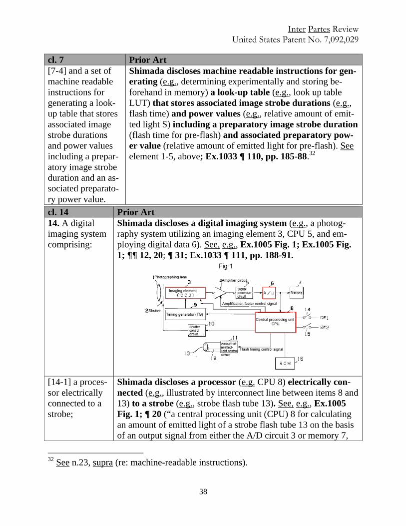
Shimada discloses a digital imaging system (e.g., a photog-raphy system utilizing an imaging element 3, CPU 5, and em-ploying digital data 6). See, e.g., Ex.1005 Fig. 1; Ex.1005 Fig. 1; ¶¶ 12, 20; ¶ 31; Ex.1033 ¶ 111, pp. 188-91.
[14-1] a proces-sor electrically connected to a strobe;
Shimada discloses a processor (e.g. CPU 8) electrically con-nected (e.g., illustrated by interconnect line between items 8 and 13) to a strobe (e.g., strobe flash tube 13). See, e.g., Ex.1005 Fig. 1; ¶ 20 (“a central processing unit (CPU) 8 for calculating an amount of emitted light of a strobe flash tube 13 on the basis of an output signal from either the A/D circuit 3 or memory 7,
32 See n.23, supra (re: machine-readable instructions).
Inter Partes Review United States Patent No. 7,092,029
39
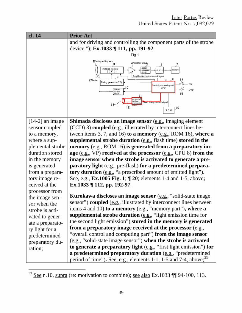
cl. 14 Prior Art and for driving and controlling the component parts of the strobe device.”); Ex.1033 ¶ 111, pp. 191-92.
[14-2] an image sensor coupled to a memory, where a sup-plemental strobe duration stored in the memory is generated from a prepara-tory image re-ceived at the processor from the image sen-sor when the strobe is acti-vated to gener-ate a preparato-ry light for a predetermined preparatory du-ration;
Shimada discloses an image sensor (e.g., imaging element (CCD) 3) coupled (e.g., illustrated by interconnect lines be-tween items 3, 7, and 16) to a memory (e.g., ROM 16), where a supplemental strobe duration (e.g., flash time) stored in the memory (e.g., ROM 16) is generated from a preparatory im-age (e.g., VP) received at the processor (e.g., CPU 8) from the image sensor when the strobe is activated to generate a pre-paratory light (e.g., pre-flash) for a predetermined prepara-tory duration (e.g., “a prescribed amount of emitted light”). See, e.g., Ex.1005 Fig. 1; ¶ 20; elements 1-4 and 1-5, above; Ex.1033 ¶ 112, pp. 192-97.
Kurokawa discloses an image sensor (e.g., “solid-state image sensor”) coupled (e.g., illustrated by interconnect lines between items 4 and 10) to a memory (e.g., “memory part”), where a supplemental strobe duration (e.g., “light emission time for the second light emission”) stored in the memory is generated from a preparatory image received at the processor (e.g., “overall control and computing part”) from the image sensor (e.g., “solid-state image sensor”) when the strobe is activated to generate a preparatory light (e.g., “first light emission”) for a predetermined preparatory duration (e.g., “predetermined period of time”). See, e.g., elements 1-1, 1-5 and 7-4, above;33
33 See n.10, supra (re: motivation to combine); see also Ex.1033 ¶¶ 94-100, 113.

Inter Partes Review United States Patent No. 7,092,029
40
cl. 14 Prior Art see also Fig. 1; Ex.1033 ¶ 113, pp. 197-201.
[14-3] wherein the processor accesses a look-up table in the memory that stores image strobe durations and power val-ues including a preparatory im-age strobe dura-tion and an as-sociated prepar-atory power value.
Shimada discloses an imaging system wherein the processor (e.g., CPU) accesses a look-up table (e.g., look-up table LUT) in the memory that stores image strobe durations (e.g., flash time) and power values (e.g., relative amount of emitted light S) including a preparatory image strobe duration (e.g., flash time for pre-flash) and an associated preparatory power val-ue (e.g., relative amount of emitted light for pre-flash).34 See, e.g., elements 1-5 and 14-2, above.35 See, e.g., Ex.1005 at Table 1 (¶ 32); ¶ 31 (“[A] LUT (Table 1) representing the relationship between the relative amount of emitted light and the flash time is stored beforehand in storage means as a file, and the flash time of a main flash is determined by referring thereto to decide the actual amount of emitted light.”); ¶ 34 (“[T]he flash time of the strobe is controlled by ... referring to the LUT for a flash time that corresponds to the relative amount of emitted light re-quired to obtain the proper exposure computed on the basis of a pre-flash. Actually, the amount of emitted light in a full flash at main flash time is regarded as 100%, and the relative amount of
34 See n.19, supra; see also Ex.1033 ¶ 114.
35 Shimada discloses a LUT stored in memory, storing associated image strobe du-
rations (flash times) and power values (S). See, e.g., Ex.1005 ¶¶ 32, 34, 44-45.
Relative amount of emitted light S is expressed as a percentage of the full flash
emission. The LUT stores, as entries, a power value S and an associated flash dura-
tion (flash time) required for obtaining the power value S. Id. ¶ 34. During camera
exposure, the processor accesses the LUT to obtain the “flash time that corre-
sponds to the relative amount emitted light required to obtain the proper exposure
computed on the basis of a pre-flash.” Id. ¶ 34; see also id. ¶¶ 37-45, pp. 201-02.
Inter Partes Review United States Patent No. 7,092,029
41
cl. 14 Prior Art emitted light is expressed as a percentage thereof.”); ¶¶ 39; 42-45; 4-7; 32; 37-38; Ex.1033 ¶ 114, pp. 201-05.
Claim 16 Prior Art 16. The digital image system of claim 14
See, e.g., claim 14.
[16-1] wherein the memory has a weighting ta-ble that stores the luminance
Shimada36 discloses that the memory (e.g., ROM 16) has a weighting table that stores the luminance weighting (e.g., cen-ter weightings or outer weightings). See, e.g., element 1-3, above; Ex.1005 ¶ 34; Ex.1033 ¶ 115, pp. 205-07.
Sugimoto discloses a memory (e.g., memory control circuit) that has a weighting table (e.g., first 28 and second 30 weighting
36 To the extent it is argued that Shimada does not disclose a memory with “a
weighting table that stores the luminance weighting,” this limitation is at minimum
obvious in view of the knowledge of a POSITA. See Ex.1033 ¶ 115. Specifically,
Shimada discloses a preparatory image partitioned into 64 regions and backlight
detection performed using the ratio of a center weighting, which uses only the four
center regions, and an outer weighting, which uses only the outer 60 regions. A
POSITA would have understood that Shimada’s disclosure of “processing only the
signals of the required photometric area,” could advantageously be accomplished
by a memory having “luminance weighting tables” which enable the CPU to iden-
tify the shaded portion and the wider area, and would have found this to be an ob-
vious and straightforward implementation choice. See id; Ex.1033 p. 206.
Inter Partes Review United States Patent No. 7,092,029
42
Claim 16 Prior Art weighting. amount tables) that stores the luminance weighting (e.g.,
weighting amount data K).37 See, e.g., Ex.1004 Fig. 1, 5, 6; 6:17-31 (“[L]uminance data Dy ... is inputted to a weighting circuit 22…. [which] subjects the luminance data to a weighting opera-tion Dy in accordance with weighting amount data K held in a first weighting amount table 28 or a second weighting amount ta-ble 30.”). See also id. 13:44-58; Ex.1033 ¶ 116, pp. 207-13.
D. Grounds 3 and 4
1. Motivation to Combine Sugimoto with Shimada
A POSITA would have been motivated and found it obvious to implement
Sugimoto’s camera system and associated methods of flash operation using Shi-
mada’s teachings regarding using a LUT associating relative light emissions with
strobe durations in order to arrive at the strobe duration which would effectuate the
desired light emission amount for a main flash. This motivation is confirmed by,
for example, the references’ overlapping disclosures and similar purposes dis-
cussed above in § V.C.4, and by Sugimoto’s teaching of an advantageous method
(using a LUT) of carrying out a critical step (calculating the main flash duration
and firing the main flash) that is expressly disclosed by Sugimoto but without spec-
ifying a particular means of carrying out that step. See Ex.1033 ¶ 121. More specif-
37 To the extent it is argued that Shimada does not disclose this limitation, at mini-
mum, Shimada in view of Sugimoto renders this element obvious. See Ex.1033 ¶¶
87-93, 116, pp. 208-13.

Inter Partes Review United States Patent No. 7,092,029
43
ically, Sugimoto does not explicitly identify the means of determining “a period
equal to the major light-emission amount Q,” Ex.1004 11:39-46, but there are only
a relatively small, finite number of identified, predictable solutions for practically
and effectively obtaining the strobe duration corresponding to a desired quantity of
light from a strobe, see Ex.1033 ¶ 122. One such solution is to use an empirical
LUT as expressly disclosed in Shimada. See id.; see also Ex.1005 ¶¶ 33-35.38 Ac-
cordingly, a POSITA would have been motivated and found it obvious and
straightforward to employ Shimada’s teachings of using a LUT as a means of de-
riving the necessary strobe duration for the emission of a desired quantity of light
as described by Sugimoto. See Ex.1033 ¶ 122; see also § V.C.4, supra; n.8, supra.
2. Motivation to Combine Sugimoto with Kurokawa
A POSITA would have been motivated to implement Sugimoto’s camera
and flash system using Kurokawa’s teachings regarding both using a pre-flash of a
predetermined duration and using a LUT in order to arrive at the proper main flash
duration. See Ex.1033 ¶¶ 124-32. First, Sugimoto and Kurokawa have overlapping
disclosures and similar purposes. The explicit teachings of both relate to improved
methods of flash photography, and in particular involve: (1) calculating the dura- 38 A second solution would be to use an algorithm. See Ex.1033 ¶ 122. But, as Shi-
mada teaches, the flash intensity profile of a strobe is non-linear, potentially mak-
ing an algorithm too complex or impractical. See Ex.1005 ¶ 6; Ex.1033 ¶ 122.
Inter Partes Review United States Patent No. 7,092,029
44
tion of a main flash by using a pre-flash on the basis of the luminance of the pre-
paratory image; (2) a pre-flash duration that is less than the main flash duration;
and (3) capturing less light in the pre-flash than in the main flash. See, e.g.,
Ex.1004 Abstract, 1:56-2:9, Fig. 13A; Ex.1010 Abstract; 2:52-57; 5:47-6:4. This
confirms a motivation to combine the teachings of these references in implement-
ing systems involving their overlapping subject matter. See Ex.1033 ¶ 125.
More specifically, a POSITA would have been motivated to employ Kuro-
kawa’s advantageous teachings of the use of a predetermined pre-flash duration in
implementing the camera system of Sugimoto based on Sugimoto’s disclosures
that: (1) an object of the invention is to provide a means of “precisely calculating a
major light-emission element of a flash lamp,” Ex.1004 1:49-52; and (2) there is a
direct relationship between flash output and flash time, such that “the longer the
light-emission period is, the larger the light-emission amount is,” id. 7:57-60. To
determine the duration (which corresponds to the output) of the main flash, it is
necessary to know the output of the pre-flash. See Ex.1033 ¶ 126. As Sugimoto
makes clear, see Ex.1004 7:57-60, and as a POSITA would have known, see
Ex.1033 ¶ 126, one method of setting the amount of light is to set the flash dura-
tion as described in Kurokawa.
A POSITA also would have been motivated to employ Kurokawa’s teach-
ings of the use of a LUT in implementing Sugimoto’s system because, as discussed,
Inter Partes Review United States Patent No. 7,092,029
45
supra at V.D.1, Sugimoto presents a critical step (calculating the main flash dura-
tion and firing the main flash) without identifying an explicit means of carrying it
out, while Kurokawa provides an advantageous and helpful method of carrying out
this step (by using a LUT).39 See Ex.1033 ¶ 130. More specifically, Sugimoto does
not explicitly identify the means of determining “a period equal to the major light-
emission amount Q,” Ex.1004 11:39-46, but there are only a relatively small, finite
number of identified, predictable solutions for practically and effectively obtaining
the strobe duration corresponding to a desired quantity of light from a strobe, see
Ex.1033 ¶ 131. One such solution is to use an empirical LUT as expressly dis-
closed in Kurokawa. See id.; see also Ex. 1010 at 5:66-6:4, Fig. 3; n. 38, supra.
Accordingly, a POSITA would have been motivated and found it obvious and
straightforward to employ Kurokawa’s teachings of using a LUT as a means of de-
riving the necessary the strobe duration for the emission of a desired quantity of
light as described by Sugimoto. See Ex.1033 ¶ 131.
Additionally, Kurokawa provides an advantageous means of setting the out-
put of the pre-flash by setting duration. See, e.g., Ex.1010 7:28-30; 7:21-23). In-
deed, a POSITA would have known, consistent with the teachings of Kurokawa,
39 A POSITA would also have been motivated to make this combination for at least
the same reasons as described in § V.D.1, supra. See Ex.1033 ¶¶ 119-23.
Inter Partes Review United States Patent No. 7,092,029
46
that using a pre-flash of predetermined duration is advantageous (i.e., “a great ad-
vantage in respect to the cost of manufacture and development of products,” id.
5:35-47; 7:19-45), because it means that there is a need for only one type of LUT
(i.e., a table correlating flash duration and flash output), and the system “obviates
the necessity of any additional detecting circuit ... and any table or any related for-
mula for deciding the light emission time according to the remaining charging
voltage,” id. 7:39-43. Moreover, Kurokawa teaches that it is advantageous to use a
predetermined pre-flash duration in order to provide a fixed amount of preliminary
light that is smaller than the amount at full flash, such that the discharge voltage is
minimized and the remaining charging voltage of the flash is kept constant after
the pre-flash, in order to obviate the need for a camera with more than one look-up
table or a voltage detecting circuit. See id. 7:33-43. When implementing the pre-
flash step of Sugimoto, a POSITA would thus have been motivated to employ Ku-
rokawa’s teaching of advantageously using a predetermined pre-flash duration to
improve the system of Sugimoto. See Ex.1033 ¶ 127.
3. Grounds 3 and 4 Claim Charts for Claims 1, 6, 7, 14, and 16
Claim 1 Prior Art 1. A method of adjusting image lighting, the meth-
Sugimoto teaches a method of adjusting image lighting (e.g., de-termines proper flash duration). See, e.g., Ex.1004 Figs. 7-12 (disclosing method for calculating major light emission amount Q in steps S1-S45); Figs. 10-12; Title (“Digital camera, having a flash unit, which determines proper flash duration through an assessment of image luminance and, where needed, a preliminary flash emis-
Inter Partes Review United States Patent No. 7,092,029
47
Claim 1 Prior Art od com-prising:
sion.”); Abstract (“A digital camera includes a flash lamp and a CCD imager.... The microcomputer succeedingly makes the flash lamp perform a preliminary light-emission, and exposes the CCD imager by 1/1500 seconds. The calculator evaluates the luminance evaluation value on the basis of the luminance signal … calculates a major light-emission amount....”); see also Ex.1033 pp. 215-17.
[1-1] generat-ing a pre-paratory light for a predeter-mined preparato-ry dura-tion;
Sugimoto teaches generating a preparatory light (e.g., “prelimi-nary light-emission”) for a predetermined preparatory duration (e.g., preliminary light-emission in the amount P).40 See e.g., Ex.1004 at 10:62-11:2 (“If the flash lamp 38 receives the flash in-struction for the preliminary light-emission, the flash lamp 38 emits the light … during the exposure of the CCD imager 12. In addition, this light-emission state is called as the preliminary light-emission state that the light-emission is preliminarily performed before the major light-emission described later.”); see also id. 11:41-46; Ex.1033 ¶ 133, pp. 217-19.
Kurokawa41 teaches generating (e.g., “making”) a preparatory light (e.g., “first light emission”) for a predetermined preparatory
40 It would have been obvious to a POSITA, who would have known that flashes
have known outputs (and that “the longer the light-emission period is, the larger
the light-emission amount is,” Ex.1004 7:57-60; see also id. 10:67-11:2), that one
way of generating a pre-flash to emit a “set” amount of light would be to generate
the pre-flash for a predetermined duration. See Ex.1033 ¶ 133, p. 218.
41 To the extent it is argued that Sugimoto does not disclose this limitation, a
POSITA would at minimum have been motivated and found it obvious to employ
Kurokawa’s teachings of predetermined preparatory duration in implementing the
system of Sugimoto. See § V.D.2, supra; Ex.1033 ¶¶ 125-29, 134, pp. 221-23.

Inter Partes Review United States Patent No. 7,092,029
48
Claim 1 Prior Art duration (e.g., “predetermined period of time”). See, e.g., Ex.1010 Abstract (“[T]he control part…causes the light emission part to emit light for a predetermined period of time….”); 4:62-5:17 (“[A] pre-liminary exposure is performed by making a first light emission for a predetermined period of time….”); 7:19-23; 9:28-45; see also id. 2:10-37; 10:56-64; cls. 1, 2; Ex.1033 ¶ 134, pp. 219-23.
[1-2] cap-turing a preparato-ry image while generat-ing the preparato-ry light, wherein the pre-paratory image is represent-ed by preparato-ry image data;
Sugimoto teaches capturing a preparatory image (e.g., exposure of the CCD imager 12 during preliminary light-emission) while gen-erating the preparatory light (e.g., “preliminary light-emission”), wherein the preparatory image is represented by preparatory image data (e.g., “luminance data Dy” and/or “color data R, G, B”; image data is obtained by the Analog-to-Digital (A/D) converter). See, e.g., Ex.1004 5:34-39 (“[A]n A/D converter…successively dig-itizes the image signal outputted from the CCD imager 12…and an output of the A/D converter 14 is sequentially written to a RAM 16 as image data.”); 10:58-11:13 (“If the flash lamp 38 receives the flash instruction for the preliminary light-emission, the flash lamp 38 emits the light such as the light-emission amount becomes P during the exposure of the CCD imager 12.... the image data obtained is written into the RAM 16.”); see also id. 5:57-6:31; 7:29-40; 9:1-14; Ex.1033 ¶ 135, pp. 223-26.
[1-3] de-termining an aver-age pre-paratory image lumi-nance of the pre-paratory
Sugimoto teaches determining an average preparatory image luminance of the preparatory image (e.g., “luminance evaluation value Vy in the preliminary light emission” and/or “preliminary light-emission luminance evaluation value Ys”) based on the pre-paratory image data (e.g., image data from the CCD imager ex-posed during the preliminary light-emission) and weighting at least a subset of the preparatory image data (e.g., luminance data Dy weighed by weighting circuit 22 in annotated Fig. 1 and luminance weighting tables in Figs. 5, 6).42 See, e.g., Ex.1004 Fig. 1 (excerpt), 5, 6; 9:1-25 (“[T]he image data generated by this exposure is written
42 See n.15, supra; Ex.1033 ¶ 136, p. 226.

Inter Partes Review United States Patent No. 7,092,029
49
Claim 1 Prior Art image based on the pre-paratory image da-ta and weighting at least a subset of the pre-paratory image da-ta;
into the RAM 16, thereafter, the calculator 20 calculates the lumi-nance data and the color difference data on the basis of the image da-ta. Only the luminance data Dy is subjected to the weighting opera-tion in the weighting circuit 22 in accordance with the weighting
amount data K stored in the first weighting amount table 28, whereby the luminance data, having attached importance to the center of the screen, is obtained. The integrator 24 digitally integrates the luminance data equal to 1 frame, and the accumulator 26 di-vides the integrated value by the total sum of the weighting amount data,
whereby the luminance evaluation value Vy is calculated attaching importance to the center of the screen….”); 6:17-7:21; 7:29-41; Fig. 6; 3:11-25; 11:3-13; 13:44-58; Ex.1033 ¶ 136, pp. 226-32.
[1-4] generat-ing a sup-plemental strobe du-ration based on the aver-age pre-paratory image lumi-nance and
Sugimoto teaches generating a supplemental strobe duration (e.g., the duration associated with major light-emission amount Q) based on the average preparatory image luminance (e.g., “pre-liminary light-emission luminance evaluation value Ys”) and lumi-nance weightings (e.g., “weighting amount data K”).43 See, e.g., Ex.1004 11:42-46 (“[T]he microcomputer 32 outputs the flash in-struction for the major light-emission to the flash lamp 38, and the flash lamp 38 emits the light during the exposure of the CCD imager 12 by a period equal to the major light-emission amount Q….”); 10:45-11:46 (“…The microcomputer 32 regards the luminance eval-uation value Vy in the preliminary light-emission as a preliminary light-emission luminance evaluation value Ys in a step S43. Thereaf-ter, the microcomputer 32 calculates a major light-emission amount
43 Sugimoto teaches generating a supplemental strobe duration (e.g., major light-
emission amount Q) based on average preparatory image luminance (e.g., Ys) and
luminance weightings (e.g., K). See, e.g., Ex.1004 11:14-46; element 1-3, above;
Ex.1033 ¶ 137, p. 223.

Inter Partes Review United States Patent No. 7,092,029
50
Claim 1 Prior Art lumi-nance weight-ings;
Q of the flash lamp 38 in the major light-emission in accordance with a following equation in a step S45. Q=(U/Ys)xP. In this equa-tion, by dividing the shortage amount U of the luminance by the pre-liminary light-emission luminance evaluation value Ys, how many times of the evaluation value obtained by one preliminary light-emission is necessary to supplement the shortage amount is calculat-ed, and furthermore, by multiplying the light-emission amount in the preliminary light-emission with a magnification calculated, the major light-emission amount Q is finally obtained…. On the other hand, the microcomputer 32 outputs the flash instruction for the major light-emission to the flash lamp 38, and the flash lamp 38 emits the light during the exposure of the CCD imager 12 by a period equal to the major light-emission amount Q in a step S51.”); see also id. 7:29-40; 13:44-58; Ex.1033 ¶ 137, pp. 232-36.
[1-5] and generat-ing a look-up table stor-ing asso-ciated image strobe du-rations and pow-er values including a prepara-tory im-
Shimada44 teaches generating (e.g., determining experimentally and storing beforehand in memory) a look-up table (e.g., look up table LUT) storing associated image strobe durations (e.g., “flash time”) and power values (e.g., relative amount of emitted light S) including a preparatory image strobe duration (e.g., flash time for pre-flash) and associated preparatory power value (e.g., rela-tive amount of emitted light for pre-flash).45 See, e.g., Ex.1005 at Table 1 (¶ 32); ¶ 6 (“[T]echnical means for using a table in which the relationship between the flash time and the amount of emitted light has been determined via experimentation beforehand, and ob-taining the desired amount of emitted light by controlling the flash time has been proposed.”); ¶ 34 (“[T]he flash time of the strobe is controlled by storing beforehand as a file in storage means a LUT which represents the relationship between a relative amount of emit-ted light…and a flash time…and referring to the LUT for a flash
44 For reasons discussed above, a POSITA would have been motivated to employ
the LUT of Shimada in implementing the camera system of Sugimoto. See § V.D.1,
supra; see also n.8, supra (re: motivation to combine); Ex.1033 pp. 242-44.
45 See n.19, supra; see also Ex.1033 ¶¶ 120-23, 139-40, pp. 237-38.
Inter Partes Review United States Patent No. 7,092,029
51
Claim 1 Prior Art age strobe duration and asso-ciated preparato-ry power value.
time….”); ¶¶ 39; 42; see also id. ¶¶ 4-5, 7, 37-38, 43-45; Ex.1033 ¶¶ 138-40, pp. 236-44.46, 47
Kurokawa discloses generating a look-up table (e.g., “table of guide numbers and light emission times”) storing associated image strobe durations (e.g., light emission times”) and power values (e.g., “guide numbers”) including a preparatory image strobe du-ration and associated preparatory power value. See, e.g., Ex.1010 Fig. 3; 5:66-6:4 (“[O]verall control and computing part 9 computes a light emission time for the second light emission accord-ing to the guide number computed at the step S217 by using also a table of guide numbers and light emission times, which is as shown in FIG. 3 indicating the characteristic of the flash emission part 15 in use.”); 10:26-39; see also id. 5:47-65; 10:9-25; Fig. 3; Ex.1033 ¶¶ 141-42, pp. 244-50.48, 49
46 Shimada discloses a LUT that is determined experimentally and stored in
memory. See, e.g., Ex.1005 ¶¶ 6, 32, 34. The LUT stores, as entries, power values
(e.g., S) and associated image strobe durations (e.g., flash times) required for ob-
taining the power value. See, e.g., id.; ¶¶ 34, 44, 45. The relative amount of emitted
light S is expressed as a percentage of the full flash light emission. See, e.g., id. ¶¶
7, 34; Ex.1033 ¶¶ 69, 70, 139, pp. 237-38.
47 See n.19, supra; see also Ex.1033 ¶¶ 139, pp. 237-38.
48 At minimum, a POSITA would have been motivated to employ Kurokawa’s
teachings of a LUT in implementing Sugimoto’s camera system. See § V.D.2, su-
pra. Further, to the extent that it is argued that Kurokawa does not disclose a LUT
“including a preparatory image strobe duration and associated preparatory power

Inter Partes Review United States Patent No. 7,092,029
52
Claim 6 Prior Art 6. The method of claim 1 further comprising:
See claim 1 above.
accessing the look-up table based on the average image luminance.
Shimada teaches accessing the look-up table (e.g., “re-ferring to the LUT”) based on the average image lumi-nance (e.g., “the image data average value VP obtained as a result of the . . . pre-flash that was actually performed”).
See, e.g., element 1-5, above; see also Ex.1005 at Table 1; ¶¶ 6-7; 32; 41-45; Ex.1033 ¶¶ 143-44, pp. 250-54.50
Kurokawa51 teaches accessing the look-up table (e.g.,
value,” it would at minimum have been obvious to a POSITA to include the prede-
termined duration for the preliminary light emission and the associated guide num-
ber in the LUT. See Ex.1033 ¶ 129-32, 141, p. 245.
49 A POSITA would have understood that the existence of a LUT necessarily, and
thus inherently, requires generation of that LUT. Ex.1033 ¶¶ 141-42, p. 244. To the
extent it is argued any further disclosure is required, it would at minimum have
been obvious to a POSITA in light of the use of a LUT in Kurokawa to generate
such a LUT. Ex.1033 ¶¶ 141-42, pp. 244-45.
50 See n.44, supra (re: motivation to combine); see also § V.D.1, supra; Ex. 1033 ¶¶
120-23, 144, pp. 252-54.
51 See n.48, supra (re: motivation to combine); see also § V.D.2, supra; Ex. 1033 ¶¶
124-32, 145, pp. 244-50, 254-57.
Inter Partes Review United States Patent No. 7,092,029
53
Claim 6 Prior Art “table of guide numbers and light emission times”) based on the image luminance (e.g., “measured light value”).52 See, e.g., Ex.1010 at Fig. 3; 5:66- 6:12; 10:26-39; 5:47-65; 10:9-25; Ex.1033 ¶¶ 145, 124-32, pp. 244-50, 254-57.
Claim 7 Prior Art 7. A memory having machine readable instructions for exe-cution by a proces-sor to adjust image lighting, the
Sugimoto discloses a memory (e.g., “RAM 16”; “memory 32a”) having machine readable instructions (e.g., “flash instruction”; “shutter release instruction”) for execution by a processor (e.g., “microcomputer 32”) to adjust image lighting. See, e.g., element 1; Ex.1004 Fig. 1; 8:52-56; 10:58-11:46; see also id. 10:35-44; 6:17-
52 Kurokawa discloses calculating the guide number for the main flash exposure
from the preparatory image luminance. See Ex.1010 5:47-65. The LUT entry asso-
ciated with the calculated guide number provides the main flash duration needed to
produce a suitable image. See id. 5:66-6:4; see also Ex.1033 ¶ 141; p. 255.
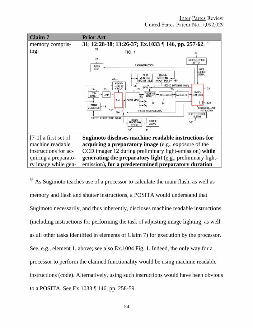
Inter Partes Review United States Patent No. 7,092,029
54
Claim 7 Prior Art memory compris-ing:
31; 12:28-38; 13:26-37; Ex.1033 ¶ 146, pp. 257-62. 53
[7-1] a first set of machine readable instructions for ac-quiring a preparato-ry image while gen-
Sugimoto discloses machine readable instructions for acquiring a preparatory image (e.g., exposure of the CCD imager 12 during preliminary light-emission) while generating the preparatory light (e.g., preliminary light-emission), for a predetermined preparatory duration
53 As Sugimoto teaches use of a processor to calculate the main flash, as well as
memory and flash and shutter instructions, a POSITA would understand that
Sugimoto necessarily, and thus inherently, discloses machine readable instructions
(including instructions for performing the task of adjusting image lighting, as well
as all other tasks identified in elements of Claim 7) for execution by the processor.
See, e.g., element 1, above; see also Ex.1004 Fig. 1. Indeed, the only way for a
processor to perform the claimed functionality would be using machine readable
instructions (code). Alternatively, using such instructions would have been obvious
to a POSITA. See Ex.1033 ¶ 146, pp. 258-59.
Inter Partes Review United States Patent No. 7,092,029
55
Claim 7 Prior Art erating a preparato-ry light for a prede-termined preparato-ry duration;
(e.g., preliminary light-emission amount becomes P). See, e.g., elements 1-1 and 1-2; Ex.1033 ¶ 146, pp. 262-63.54
Kurokawa teaches machine readable instructions for acquiring a preparatory image (e.g., exposure of the sol-id-state image sensor) while generating (e.g., “making”) a preparatory light (e.g., “first light emission”) for a predetermined preparatory duration (e.g., “predeter-mined period of time”). See, e.g., element 1-1, above; Ex.1033 ¶ 146, pp. 263-69.55
[7-2] a second set of machine readable instructions for de-termining an aver-age preparatory im-age luminance based on preparato-ry image data asso-ciated with the pre-paratory image and weighting at least a subset of the pre-paratory image data;
Sugimoto discloses machine readable instructions for determining an average preparatory image luminance (e.g., “luminance evaluation value Vy in the preliminary light emission” and/or “preliminary light-emission lumi-nance evaluation value Ys”) based on preparatory image data associated with the preparatory image (e.g., “lu-minance data Dy” and/or “color data R, G, B”; image data is obtained by the Analog-to-Digital (A/D) converter) and weighting at least a subset of the preparatory image data. See, e.g., element 1-3, above; Ex.1033 ¶ 146, pp. 269-70.56
[7-3] a third set of machine readable instructions for gen-erating a supple-mental strobe dura-tion based on the
Sugimoto discloses machine readable instructions for generating a supplemental strobe duration (e.g., the du-ration associated with major light-emission amount Q) based on the average preparatory image luminance (e.g., preliminary light-emission luminance evaluation value Ys) and luminance weightings (e.g., weighting
54 See n.53, supra (re: machine-readable instructions).
55 See n.41, supra (re: motivation to combine); § V.D.2, supra; n.25, supra.
56 See n.53, supra (re: machine-readable instructions).
Inter Partes Review United States Patent No. 7,092,029
56
Claim 7 Prior Art average preparatory image luminance and luminance weightings;
amount data K). See, e.g., element 1-4, above; Ex.1033 ¶ 146, pp. 270-71.57
[7-4] and a set of machine readable instructions for gen-erating a look-up table that stores as-sociated image strobe durations and power values in-cluding a preparato-ry image strobe du-ration and an asso-ciated preparatory power value.
Shimada discloses machine readable instructions for generating (e.g., determining experimentally and storing beforehand in memory) a look-up table (e.g., look up ta-ble LUT) that stores associated image strobe durations (e.g., flash time) and power values (e.g., relative amount of emitted light S) including a preparatory image strobe duration (flash time for pre-flash) and associated pre-paratory power value (relative amount of emitted light for pre-flash). See, e.g., 1-5, above; Ex.1033 ¶ 146, pp. 271-76.58
Kurokawa discloses machine readable instructions for generating a look-up table (e.g., “table of guide numbers and light emission times”) that stores associated image strobe durations (e.g., light emission times”) and power values (e.g., “guide numbers”) including a preparatory image strobe duration and an associated preparatory power value.59 See, e.g., 1-5, above; Ex.1033 ¶ 146, pp. 276-80.
Claim 14 Prior Art 14. A digi-tal imag-ing system compris-ing:
Sugimoto discloses a digital imaging system (e.g., photography system utilizing a microcomputer and employing digital data). See, e.g., Ex.1004 Fig. 1; Title (“Digital camera, having a flash unit, which determines proper flash duration through an assessment of image luminance and, where needed, a preliminary flash emis-sion.”); Abstract; see also Ex.1033 ¶ 147, pp. 280-81.
[14-1] a Sugimoto discloses a processor (e.g., microcomputer) electrically
57 See n.53, supra (re: machine-readable instructions).
58 See n.44, supra (re: motivation to combine); § V.D.1, supra; n.23, supra.
59 See n.48, supra (re: motivation to combine); § V.D.2, supra; n.25, supra.
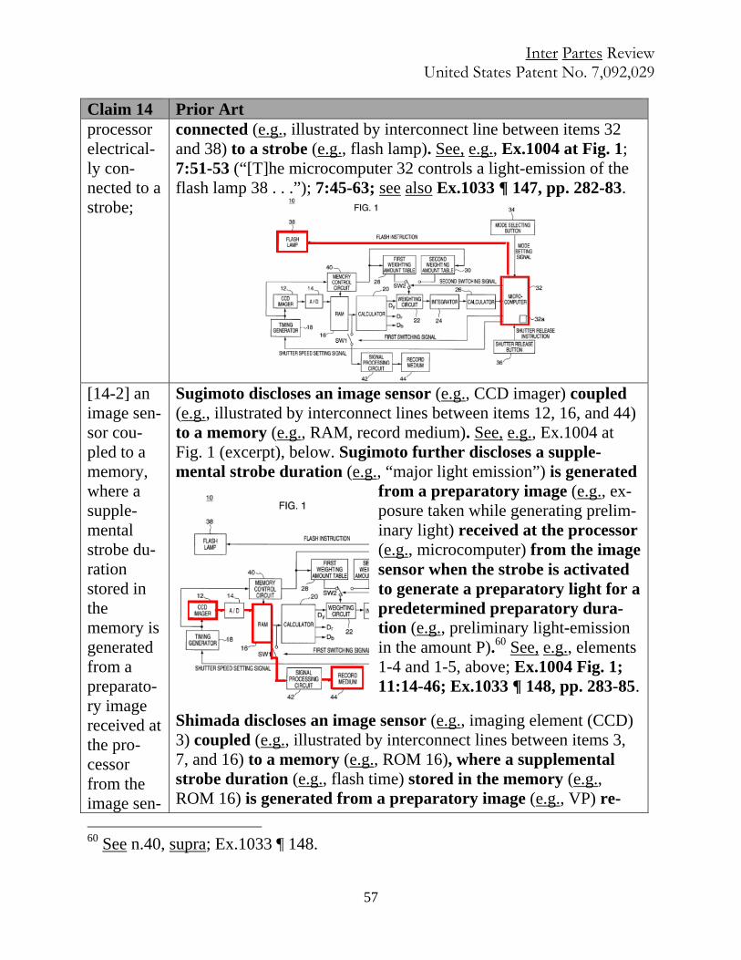
Inter Partes Review United States Patent No. 7,092,029
57
Claim 14 Prior Art processor electrical-ly con-nected to a strobe;
connected (e.g., illustrated by interconnect line between items 32 and 38) to a strobe (e.g., flash lamp). See, e.g., Ex.1004 at Fig. 1; 7:51-53 (“[T]he microcomputer 32 controls a light-emission of the flash lamp 38 . . .”); 7:45-63; see also Ex.1033 ¶ 147, pp. 282-83.
[14-2] an image sen-sor cou-pled to a memory, where a supple-mental strobe du-ration stored in the memory is generated from a preparato-ry image received at the pro-cessor from the image sen-
Sugimoto discloses an image sensor (e.g., CCD imager) coupled (e.g., illustrated by interconnect lines between items 12, 16, and 44) to a memory (e.g., RAM, record medium). See, e.g., Ex.1004 at Fig. 1 (excerpt), below. Sugimoto further discloses a supple-mental strobe duration (e.g., “major light emission”) is generated
from a preparatory image (e.g., ex-posure taken while generating prelim-inary light) received at the processor (e.g., microcomputer) from the image sensor when the strobe is activated to generate a preparatory light for a predetermined preparatory dura-tion (e.g., preliminary light-emission in the amount P).60 See, e.g., elements 1-4 and 1-5, above; Ex.1004 Fig. 1; 11:14-46; Ex.1033 ¶ 148, pp. 283-85.
Shimada discloses an image sensor (e.g., imaging element (CCD) 3) coupled (e.g., illustrated by interconnect lines between items 3, 7, and 16) to a memory (e.g., ROM 16), where a supplemental strobe duration (e.g., flash time) stored in the memory (e.g., ROM 16) is generated from a preparatory image (e.g., VP) re-
60 See n.40, supra; Ex.1033 ¶ 148.
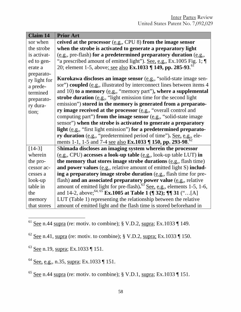
Inter Partes Review United States Patent No. 7,092,029
58
Claim 14 Prior Art sor when the strobe is activat-ed to gen-erate a preparato-ry light for a prede-termined preparato-ry dura-tion;
ceived at the processor (e.g., CPU 8) from the image sensor when the strobe is activated to generate a preparatory light (e.g., pre-flash) for a predetermined preparatory duration (e.g., “a prescribed amount of emitted light”). See, e.g., Ex.1005 Fig. 1; ¶ 20; element 1-5, above; see also Ex.1033 ¶ 149, pp. 285-93.61
Kurokawa discloses an image sensor (e.g., “solid-state image sen-sor”) coupled (e.g., illustrated by interconnect lines between items 4 and 10) to a memory (e.g., “memory part”), where a supplemental strobe duration (e.g., “light emission time for the second light emission”) stored in the memory is generated from a preparato-ry image received at the processor (e.g., “overall control and computing part”) from the image sensor (e.g., “solid-state image sensor”) when the strobe is activated to generate a preparatory light (e.g., “first light emission”) for a predetermined preparato-ry duration (e.g., “predetermined period of time”). See, e.g., ele-ments 1-1, 1-5 and 7-4 see also Ex.1033 ¶ 150, pp. 293-98.62
[14-3] wherein the pro-cessor ac-cesses a look-up table in the memory that stores
Shimada discloses an imaging system wherein the processor (e.g., CPU) accesses a look-up table (e.g., look-up table LUT) in the memory that stores image strobe durations (e.g., flash time) and power values (e.g., relative amount of emitted light S) includ-ing a preparatory image strobe duration (e.g., flash time for pre-flash) and an associated preparatory power value (e.g., relative amount of emitted light for pre-flash).63 See, e.g., elements 1-5, 1-6, and 14-2, above;64, 65 Ex.1005 at Table 1 (¶ 32); ¶¶ 31 (“…[A] LUT (Table 1) representing the relationship between the relative amount of emitted light and the flash time is stored beforehand in
61 See n.44 supra (re: motiv. to combine); § V.D.2, supra; Ex.1033 ¶ 149.
62 See n.41, supra (re: motiv. to combine); § V.D.2, supra; Ex.1033 ¶ 150.
63 See n.19, supra; Ex.1033 ¶ 151.
64 See, e.g., n.35, supra; Ex.1033 ¶ 151.
65 See n.44 supra (re: motiv. to combine); § V.D.1, supra; Ex.1033 ¶ 151.

Inter Partes Review United States Patent No. 7,092,029
59
Claim 14 Prior Art image strobe du-rations and power values in-cluding a preparato-ry image strobe du-ration and an associ-ated pre-paratory power value.
storage means as a file, and the flash time of a main flash is deter-mined by referring thereto to decide the actual amount of emitted light.”); 34 (“That is, the flash time of the strobe is controlled by…referring to the LUT….”); 42; 45; see also id. ¶¶ 4-7, 32, 37-38, 43; Ex.1033 ¶ 151, pp. 298-306.
Kurokawa66, 67 discloses an imaging system wherein the proces-sor (e.g., “solid-state image sensor”) accesses a look-up table (e.g., “table of guide numbers and light emission times”) in the memory (e.g., “memory part”), that stores image strobe durations (e.g., light emission times”) and power values (e.g., “guide numbers”) including a preparatory image strobe duration and an associat-ed preparatory power value. See, e.g., Ex.1010 Fig. 3; 5:66-6:4 (“[T]he overall control and computing part 9 computes a light emis-sion time for the second light emission according to the guide num-ber computed at the step S217 by using also a table of guide num-bers and light emission times….”); see also id. 5:47-65; 10:9-25; Ex.1033 ¶¶ 152-54, pp. 306-12.
Claim 16 Prior Art 16. The digital image system of claim 14,
See claim 14.
[16-1] wherein the memory has a weighting table that stores the luminance weighting.
Sugimoto discloses a memory (e.g., memory control circuit) that has a weighting table (e.g., first and second weighting amount ta-bles) that stores the luminance weighting (e.g., weighting amount
66 It would have been obvious and straightforward to a POSITA to store the prede-
termined duration for preliminary light emission in the LUT and associate it with a
respective guide number, such that a LUT “including a preparatory image strobe
duration and associated preparatory power value.” See Ex.1033 ¶ 153, p. 307.
67 See n.48, supra; see also § V.D.2, supra; Ex.1033 ¶¶ 152-54.
Inter Partes Review United States Patent No. 7,092,029
60
Claim 16 Prior Art data K). See, e.g., Ex.1004 at Fig. 1 (excerpt below), 5, 6; 6:17-31 (“[W]eighting circuit 22 subjects the lumi-nance data to a weighting operation Dy in accordance with weighting amount data K held in a first weighting amount table….); see also id. 13:44-58; Ex.1033 ¶¶ 155-56, pp. 312-14.
VI. CONCLUSION
Because this Petition, if unrebutted, shows that there is a reasonable likeli-
hood that these claims are unpatentable, Petitioner requests this Petition be institut-
ed and the Challenged Claims be found unpatentable and canceled. Per §§ 1.33(c),
42.105, and 42.100, a copy of the present Request, in its entirety, is being served
on the Patent Owner at the address of record as reflected in the publicly available
records of the PTO as designated in the PAIR system. The Director is hereby au-
thorized to charge any deficiency in the fees filed, asserted to be filed or which
should have been filed herewith (or with any paper hereafter filed in this proceed-
ing by this firm) to Deposit Account 06-1075, under Order No. 110797-0018-652.
Respectfully submitted by: /J. Steven Baughman/ May 21, 2015
J. Steven Baughman (lead counsel) 47,414 Steven Pepe (backup counsel) 42,069 Megan F. Raymond, 72,997 ROPES & GRAY LLP ROPES & GRAY LLP 1211 Avenue of the Americas One Metro Center, 700 12th St.–Ste. 900 New York, NY 10036-8704 Washington, DC 20005-3948 P: 212-596-9046/F: 646-728-2660 P: 202-508-4606 / F: 202-383-8371 [email protected] [email protected] [email protected]
Mailing address for all PTAB correspondence: ROPES & GRAY LLP IPRM – Floor 43, Prudential Tower, 800 Boylston Street, Boston, MA 02199-3600.
Inter Partes Review United States Patent No. 7,092,029
i
IN THE UNITED STATES PATENT AND TRADEMARK OFFICE United States Patent No.: 7,092,029 § Attorney Docket No.: Inventors: Robert A. Medwick, Glen Stark § 110797-0018-652 Formerly Application No.: 09/816,038 § Customer No. 28120 Issue Date: Aug. 15, 2006 § Filing Date: Mar. 22, 2001 § Petitioners: Samsung Former Group Art Unit: 2622 § Electronics Co., Ltd.; Samsung Former Examiner: D. Ometz; K. Jerabekz § Electronics America, Inc.; § Samsung Semiconductor, Inc. For: STROBE LIGHTING SYSTEM FOR DIGITAL IMAGES MAIL STOP PATENT BOARD Patent Trial and Appeal Board United States Patent and Trademark Office Post Office Box 1450 Alexandria, Virginia 22313-1450
PETITION FOR INTER PARTES REVIEW OF UNITED STATES PATENT NO. 7,092,029
CERTIFICATE OF SERVICE
It is certified that a copy of the following documents has been served in its entirety on the
patent owner as provided in 37 CFR § 42.205:
1. Petition For Inter Partes Review of United States Patent No. 7,092,029 Pursuant
to 35 U.S.C. § 321, 37 C.F.R. § 42.304 and accompanying exhibits:
Exhibit Description Ex.1001 U.S. Patent No. 7,092,029 Ex.1002 U.S. Patent No. 7,092,029 File History Ex.1003 U.S. Prov. Appl. No. 60/192,008 Ex.1004 U.S. Patent No. 6,195,127 (“Sugimoto”) Ex.1005 Japanese Patent Appl. No. H11-119288 (“Shimada”) Ex.1006 U.S. Patent No. 5,257,063 (“Ishimaru”) Ex.1007 Japanese Patent Appl. No. H01-289925 (“Nakajima”)
Inter Partes Review United States Patent No. 7,092,029
ii
Ex.1008 U.S. Patent No. 5,987,261 (“Sugahara”) Ex.1009 U.S. Patent No. 5,652,929 (“Yasukawa”) Ex.1010 U.S. Patent No. 6,426,775 (“Kurokawa”) Ex.1011 U.S. Patent No. 4,484,807 (“Kataoka”) Ex.1012 Electronic Flash, Strobe; Harold E. Edgerton (2d ed. MIT Press 1979) Ex.1013 Electronic Flash; Jack Neubart (Silver Pixel Press 1997) Ex.1014 Fundamentals of Electronic Imaging Systems: Some Aspects of Image
Processing, W.F. Schreiber, (3rd ed. 1993) Ex.1015 Canon EOS Elan II Instructions; English Edition (1995) Ex.1016 Kodak DCS 500 Series Digital Cameras User’s Guide (2000) Ex.1017 Canon Speedlite 380EX Instructions; English Edition (1995) Ex.1018 Canon Flash Work: Taking Great Pictures with Canon Speedlites
(1999) Ex.1019 Kodak Pro DCS 520 Review, Phil Askey (February 1999) Ex.1020 Magic Lanterns Guides: Nikon SB-25 Flash System (1993) Ex.1021 Nikon D1 Camera Instruction Manual Ex.1022 Press Release – Nikon D1 Camera (June 15, 1999) Ex.1023 Nikon D1 Camera Brochure (August 22, 2000) Ex.1024 Nikon Speedlight SB-28DX Instruction Manual Ex.1025 Press Release - Nikon SB-28DX (June 15, 1999) Ex.1026 Minolta Maxxum Flash Program Flash 5400HS Instruction Manual
(1993) Ex.1027 Minolta Dynax 9/Maxxum 9 Instruction Manual (1999) Ex.1028 Popular Photography (March 1999) Ex.1029 SLR: Nikon Takes a Giant Step Forward with New N90 AF SLR, Pop-
ular Photography (October 1992) Ex.1030 Nikon N90 Instruction Manual Ex.1031 Magic Lanterns Guides: Nikon SB-28 AF Speedlite (1999) Ex.1032 Joint Submission of Disputed Claim Terms, Case No. 4:14-cv-00371 Ex.1033 Declaration of Kenneth Parulski Ex.1034 Declaration of William M. Serra
Inter Partes Review United States Patent No. 7,092,029
The copy has been served on May 21, 2015 by causing the aforementioned documents to
be deposited in the United States Postal Service as Express Mail postage pre-paid in an envelope
addressed to:
Farjami & Farjami LLP 26522 La Alameda Avenue Suite 360 Mission Viejo, CA 92691
(Label No. EF 070 059 626 US)
Respectfully submitted,
ROPES & GRAY LLP
/s/ Megan Raymond Megan F. Raymond