Embed Size (px)
Citation preview

IN THIS ISSUE:
VIDEO I -F CIRCUITS & APPLICATIONS
HOW TO COMPUTE WHAT PRICES TO CHARGE
HIGH RESISTANCE, HIGH SENSITIVITY VOLT-MILLIAMMETER
USING 'SCOPES IN RADIO SERVICING
MOBILE RADIO

Another Good Deal From MalloryTo You
The cabinet contains-one each of these MalloryVibrators -248-716-859,-870-1100-1501 and two each ofthese buffers-OT-371,OT -372, OT -373, OW -344, OW -345, OW -346.
e Ca met pro-vides space for 12vibrators and adrawer with 6 com-partments for buffercapacitors, arranged soyou can "take stock" aa glance.
The Fastest Selling Vibrators in the Finest Line Made
The Mallory "2448 Vibrator Deal"
WHAT WILL
MALLORY
DO NEXT?
See Us at
the Radio
Parts Show
Mallory, first producer of the vibrator,builder of the sturdiest, most reliablevibrators made, offers you an attractivedeal on this important replacement part.A fast moving selection of 6 vibrators,that will cover 75% of your require-ments, together with an assortment of12 buffer capacitors (2 each of 6 ratings),in an attractive metal cabinet at a netprice of $24.48 to the serviceman.
This is the serviceman's regular price for
these parts; no charge is made for the
cabinet. You sell the parts for $40.80
-make your full $16.32 profit.
Your Mallory Distributor has them in
stock for immediate delivery. Place your
order now, and get this handsome, con-
venient cabinet for your shop.
More Mallory Vibrators are in Use Than All Other Makes Combined
P.
MALLORYR. MALLORY 8 CO..Inc. CAPACITORS . .. CONTROLS ... VIBRATORS . .
SWITCHES ... RESISTORS ... RECTIFIERS ...VIBRAPACK* POWER SUPPLIES ... FILTERS
*Reg. U. S. Pat. Off.
APPROVED PRECISION PRODUCTSP. R.J4IALLO2`7 !If CO., InF.,,ILNIDIANAP:01.16

'MACH FOR KEN-ILAB--
You'll never find a better tube!"
Ken-Rad tubes have been built for 26 yearson the idea that when you please the service-man-you please everybody! By actual tube experience, servicemen
know Ken-Rad research and engineeringare outstanding. They know Ken-Rad pro-duction is painstaking-with test after test tomake doubly sure there's no higher stand-ard of performance.
Dependability, above everything else, iswhy servicemen everywhere say, "Reach forKen-Rad-you'll never find a better tube."
Practically every radio serviceman knowsKen-Rad tubes. He depends on them.
And there's plenty of reason for this con-fidence. Ken-Rads are made exclusively tomeet the exacting demands of servicemen.They're quality tubes, with stamina andendurance.
This is important. Because it takes morethan good service to build repeat business.
It takes good tubes, too. Ken-Rad tubes.Use them and you can count on custom-
ers coming back, satisfied.
,KEN.RAD049'TadePRODUCT OF GEN,ERAL ELECTRIC COMPANY
Schenectady 5, New York
TheServiceman's
Tube
C.A.MEGUIAR,ShopForanTiart,Metal Mounting Dept., where gridturns are accurately aligned in
beam type mounts. (Below) Align.ing grid turns in special jig beforewelding to supports.
RADIO SERVICE DEALER * APRIL, 1948 1

Model LX Rim Drive Constant SpeedElectric Phonograph Motor
Model RC -130 Combination Record -Changer Recorder
Model R-90 Dual -Speed, HomeRecording and Phonograph Assembly
Yes, it's your customers who will appreciate the plus featuresof General Industries' Model MX Phonomotor -split-secondpickup to full constant speed . . dependable, quiet operation . . . anda full measure of famous GI Smooth Power.
In this up-to-date motor, no detail which could contribute toincreased customer satisfaction has been overlooked. Scientificnoise elimination through accurate balancing and improvedcushioning .. . superior idler arrangement which positively elim-inates vertical wobble . . . anti -friction bearing construction forlong trouble -free service . . . are but some of the reasons why theMX stands out as the top-quality value for top-quality phono-graphs and record -changers.
From the drawing board to the final inspection line, the MX hasbeen designed, engineered and built to be the finest phonomotorof its type available. Plan NOW to give your customers the extraquality that's inherent in every General Industries' phonomotor,recorder and combination record -changer recorder. Completeinformation is available upon request.
The GENERAL INDUSTRIES Co.DEPARTMENT K ELYRIA, OHIO
2 RADIO SERVICE DEALER APRIL, 1948

EDITORIALby S. R. COWAN
Know Your Television TechniquesMany "RSD" subscribers reside in
sections of the country where at presentno television broadcasts emanate. Sometechnician -subscribers who live wherethere is no likelihood of television for ayear or two have written to us complain-ing that we devote too much of our textcontent to TV subjects, regarding whichthey have no immediate interest. hicontrast, many others who also residein away -from TV areas have recentlyexpressed the view that they are de-lighted with our pioneering efforts andthey want all the data possible on TVbecause they know that eventuallytelecasting will reach their section.
Realizing that it is practically impos-sible to keep every subscriber 100%happy with your selection of technicalarticles, this Journal's editor has pro-ceeded upon the premise that tech-nicians may as well face the inevitable,. . . TV is coming along fast; muchfaster than most people realize, andthose technicians who choose to delaytheir education in this highly involvedsubject are treading on treacherousground, and by being lackadaisical,leave themselves vulnerable to havingthe new age pass them by.
Television's ProgressThere are about 1,800 AM and 260 FM
stations in the U. S. A. Eighteen TV sta-
sources estimate that more than 60, andpossibly 80, TV stations will be function-ing before Jan. 1st, 1949.
During 1947 almost 18 million radiosets of all kinds were manufactured.Of this total 1,175,000 were FM -AMmodels and 178,570 were television sets.In addition several thousand TV kitswere sold. Production schedules for1948 call for a much greater percentageof FM and TV sets than ever before,leading one to appreciate the soundnessof the claims of some authorities thatwithin the next few years TV set saleswill hit the $600 million a year markand the 40 million people residing inthe principal 140 U. S. markets willreceive TV programs regularly.
Over a quarter -million TV sets a r (-already installed in American homes.
From the astute technician's pointof view, it is grand to contemplate thatin the not too distant future, a largepercentage of all radios subject toinstallation and servicing will representhigh-priced sets that, when serviced,allow for a high and profitable servicefee. The $9.95 type of receiver wasalways the serviceman's worst enemy.Television and FM, representing $150 to$750 cost units, are probably the greatestboon to Service Dealers since radio'sinception. Ponder this carefully for itis the Utopia we've dreamed of.
Trade Show -Chicago, May 11-14All eyes are on the industry's big event.
Only Jobbers and RMA members may attendthe first 3 days while the final day will beopen to all who wish to attend.
It is expected that much in the way of newequipment and parts, postwar developedand kept "under wraps" until now, will beshown.
Member of theAudit Bureau of
Circulations
VOL.9
NO.4
SANFORD R. COWAN, Editor & PublisherSAMUEL L. MARSHALL, Technical Editor
APRIL, 1948
Editorial 3
Trade Flashes 9
Video I -F Circuits & Applications, by S. L. Marshall. 15The basic requirements of fundamental video I -F circuits fullyexplained.
How To Compute What Price To Charge For Repairs, by P. G. Zink, Jr. 18Using the system explained, no Service Dealer can quote a money -losing price.
A High Resistance, High Sensitivity Volt-Milliammeter,by Rufus P. Turner 20
Constructional details of an extremely useful non -electronic in-strument.
Using "Scopes" for Radio Servicing, by Douglas Carpenter 21Worth -having facts about the technician's most valuable instrument
Mobile Radio, by Gerald R. Fuller 23Facts about the new communications field now open to ServiceDealers
Circuit Court 26Airline 74WG-2505A; Hoffman B503; Emerson 540A; Electron-ic Laboratories 76RU.
Shop Notes 27Eliminating hum, improving tone quality of Arvin 665; Trick forreplacing speaker cones; Treatise on records and needles bytypes; Antenna connections; Substituting a 42 for 6B5; PhilcoMystery" set, failure to tune; Sentinel 286 -PR, weak reception.
New Products 28Book Reviews 30
SANFORD L. CAHN HARRY N. REIZESNational Advertising Sales Manager Advertising Manager
BRANCH:. J. C. GALLOWAY, 816 W. 5th St., Los Angeles 13, Calif., Mutual 8335
Jean M. Wheeler David SaltmanCirculation Manager Adv. Production Manager
RADIO SERVICE DEALER (title registered U. S. Pat. Off.) is published monthly at28 Renne Ave., Pittsfield, Mass. by the Cowan Publishing Corp. Executive & EditorialOffices, 342 Madison Avenue, New York City 17, New York. Subscription rates:-United States, U. S. Possessions and Canada, $2.00 for 1 year, $3.00 for 2 years)elsewhere $3.00 per year. Single copies: 25c Printed in U. S. A. Entered as SecondClass Matter at the Post Office at Pittsfield, Mass., under the Act of March 3, 1879. Allsubscribers should allow at least three weeks for change of address. Copyright, 1948,by Cowan Publishing Corp.
RADIO SERVICE DEALER APRIL, 1948 3

eeeateina
F.
-1, -4
-mil 4
AIR KinAdee
g PORTABLEFor profits that bloom in the spring...Here's the newest from AIR KING
The "Pockette" portable. So tiny it fits inthe palm of your hand . .. so excitinglynew and different that you'll agree it'smade-to-order for the present competi-tive market. Yet the "Pockette" portablemaintains the same rigid engineeringspecifications you have found invaluablein all AIR KING radios, radio combina-tions and wire recorders.
Features designed for selling!
Loop antenna in cover...4 miniature tubes...uses 1
standard flashlight battery and 1 standard 45 -volt "B"
battery ...vinylite carrying strap... polystyrene case...
snap -lock cover...sturdy metal grill to withstand outdoor
elements. Batteries easily changed! When the lid's open,
"Pockette" is "on"... close it, and "Pockette" is "off."
Net weight: 1 lb., 11 oz. Measurements: 3''x53/4''x Vs".
READY FOR IMMEDIATE DELIVERY
Model A-425-Ebony with Nickel trim "$19.95
Model A-426-Ivory with Gold trim "$24.95
Model A-427-Maroon with Gold trim *$22.95'Len batteries. Slightly higher in Zone 2.
MODEL A-425
9 95Less batteries
Slightly higher in Zone 2.
So tiny it fits in thepalm of your hand.
AIR KING PRODUCTS CO., INC., BROOKLYN 32, NEW YORK Export Address: Air King International, 75 West Street, New York 6, N.Y.
AIR KING RADIOA, Poy44--to.4, gtecelk.K!;920Division of HYTRON RADIO & ELECTRONICS CORP.
4 RADIO SERVICE DEALER + APRIL, 1948

19 PRIZES FOR 18 IDEAS
HERE'S HOWRight now, you may have a winning idea at work in yourshop. An idea for a simple service tool which makes yourwork easier, faster, more profitable. Hytron wants to helpmake such needed tools available to all servicemen - atcost. You can cash in on your idea easily - and also helpthe other fellow.Simply obtain an official entry blank from your Hytronjobber - or write us. Answer a few simple questions on theblank. Then include a sketch with constructional details -or a photograph - or a model of your proposed tool. Mail
1ST PRIZE, JUNE
HEREARE SOMEEXAMPLES
o
Hytron's Tube Tapperand Miniature PinStraightenershowyouthekind of toolwanted . Checkoff the qualities. Simple?Yes. Practicable? Usabletime-savers. Durable?Built to last. Compact?Carry them in your pock-et. Easy and economicalto manufacture? Adaptedto mass production. TubeTapper a nickel; PinStraightener 490 - bothunder 500. Tools associ-ated with tubes preferred,but other original servicetools also acceptable.
1ST PRIZE, JULY
1ST PRIZE,
AUG.
EASY IT IS TO WINto Hytron Contest Editor. The tool should be simple, prac-ticable, durable, compact, easy and economical to manu-facture. Examples: Hytron Tube Tapper and MiniaturePin Straightener.That's all there is to it. Nothing to buy. Nothing difficult.No fancy writing. And could you use one of those beautifuldeluxe test equipments - or one of those crisp new SavingsBonds! Check the easy rules. Get an official entry blanktoday for full details on how to win. Send in as many entriesas you wish - in any or all six contests. Everyone wins aTube Tapper. Your idea may hit the jackpot. Let's go!
1ST PRIZE, OCT.
HERE ARE THE PRIZESFirst Prizes
MAY DuMont Type 274 Five -Inch Oscillograph.JUNE Radio City Products Model 665-A, the "Billion-
aire", V -T Volt -Ohm -Capacity Meter, Insula-tion Tester; and Model 705-A Signal Generator.
JULY Hickok Model 156A Indicating Traceoraeter.AUG. McMurdo Silver Model 900A "Vomax" Elec-
tronic Volt-Ohm-Milliammeter; Model 904Condenser/Resistor Tester; and Model 905A"Sparx" Dynamic Signal Tracer/Test Speaker.
SEPT. Jackson Model 641 Universal Signal Generator.OCT. Weston Model 769 High Frequency Electronic
Analyzer.
Second Prize-Each Month Third Prize-Each Month$50 U. S. Savings Bond $25 U. S. Savings Bond
Grand Prizes$200 U. S. Savings Bond - to contestant whose idea isjudged to be best of the 6 winning monthly first prizes.$200 U. S. Savings Bond - to Hytron jobber indicatedon entry blank as serving grand prize winner.
HERE ARETHE EASY RULES
WHO... Any Mona fide radio servicemanwho repairs radios for the general publicand who lives in continental United Statesis eligible for these contests, except em-ployees of Hytron, their advertising agen-cies, and their families.HOW... Get official entry blank fromyour Hytron jobber, or write us. Describeon blank your idea for a shop tool for radioservicemen. Include sketch and construc-tional details -a photo - or model. Makeyour proposed tool simple, practicable,durable, compact, easy and economical tomanufacture (preferably to sell withoutprofit at 50e or less) - like the Tube Tap-per or Miniature Pin Straightener.WHERE ...Mail to CONTEST EDITOR,HYTRON RADIO & ELECTRONICSCORP.. SALEM. MASS.WHEN... There are six monthly contests.Opening and closing dates -for each contestare the first and last days of each of themonths from May through October, 1948,inclusive. The postmark date determinesmonth of entry. Entries for final month'scontest must be postmarked before mid-night, October 31, 1948, and received byNovember 15th. At judges' discretion. un-successful entries in any month's contestmay be re -considered among followingmonths' entries. You may submit as manydifferent ideas as you wish in any or all sixmonthly contests. Use separate blank foreach entry.PRIZES ... See special listing of prizes.JUDGES Entries will be judged onoriginality, simplicity, practicability, dur-ability, compactness, and ease and econ-omy of manufacture. Judges will be: San-ford Cowan. Editor & Publisher of RadioService Dealer; W. W. MacDonald, Man-aging Editor of Electronics; Oliver Read,Chief Editor of Radio News; Joseph Roche.Editor of Radio Maintenance; J. L.Stoutenburgh. Executive Editor of Radio& Television Retailing; Lewis Winner,Chief Editor of Service.Judges' decisions final. Duplicate prizes incase of ties. No entries returned. Entriesbecome property of Hytron, who may, atits option and by special arrangement withthe entrant, pay the cost of a patent appli-cation (if the tool is patentable) with theunderstanding that Hytron is to have anon-exclusive license to manufacture, dis-tribute. and sell the tool without royalties.Contests subject to all Federal and Stateregulations. Winners will be notified bymail. Grand prize winner will be announcedin radio service trade papers shortly afterclose of final contest. Prize winner listavailable approximately one month afterclose of last contest.
SPECIALISTS IN RADIO RECEIVING TUBES SINCE 1921
'ILIVOSO TAM EILECNWEINIAtS toMAIN OFFICE: SALEM, MASSACHUSET TS
RADIO SERVICE DEALER * APRIL, 1948

Aleut Ai&New, importantadditions to themost complete lineof Speakers andDriving Units made
To the more than 60 different typeand size speakers and horn unitsthat already comprise the RACONline-these new models have beenadded. There is a RACON speakerand horn unit ideal for every con-ceivable sound system application.
RACON has not only the most com-plete line, but also the most pre-ferred line. For over 20 years leadingSoundmen have recognized and spec-ified them because of dependability,efficiency and low-cost, and becausethe reproducers are trouble proof.
Here is a partial list of the varioustypes of RACON products now available:
PM Horn Driving Units, 10 typesRe-entrant Trumpets, 7 typesTweeter & High Frequency Speak-ers, 3 typesRadial Horns and Speakers, 3
types
Straight Trumpets, 21 types Re-entrant Fone Speakers, 7 typesFlat bell straight trumpets, 2 typesArmored Cone Projectors, 7
types
In addition there are cellular and auditorium horns, inter-com, paging, monitor, and dwarf speakers, cone speakerhousings, etc., besides all basic accessories such as swivelbrackets, mounting units, cone housings, multiple horn throatcombinations, etc.
Write for free catalog
RACON ELECTRIC CO., INC.52 East 19th St. New York 3, N. Y.
RACON
NEW SPECIAL PM HORN UNIT, having Alnico V magnetring, completely watertight, housed in a heavy alumi-num spinning. Provides extremely high efficiency re-production with minimum input. Handling capacity35 watts continuous, 60 w. peak.
NEW SMALL RE-ENTRANT HORNS, extremely efficientfor factory inter -corn and paging systems; for soundtrucks, R.R. yards and all other industrial installationswhere high noise levels are prevalent. Watertight,corrosion -proof, easily installed. Two new models -type RE -11/2, complete with Baby Unit, handles 25 watts,covers 300-6000 cps; type RE -12, complete with Dwarf
NEW RADIAL RE-ENTRANT SPEAKER, excellent for alltypes of industrial sound installations. Provides super-lative and complete 360° speech intelligibility by effici-ently over-riding factory high noise levels. Frequencyresponse 300-6000 cps. Handling capacity 25 wattscontinuous, 35 w. peak. Has mounting bracket. Size 12"wide by 12s" high.
6 RADIO SERVICE DEALER APRIL, 1948

ASK FUR OU;
FAE.' 5Erk"!AAVAR.'
nER14Ott
a r Na3;ca
Work ,ket4e,NAtt.in
\K\ ,\,\\\
SALES ?
Let This Ward 1-2-3 Plan Help
You Cash in on the/ Huge
Auto Aerial Repl /cement Market
BM IBS 1111 III NB
FAULTY AERIALS CAUSE 2 OUT OF 3 CAR RADIO TROUBLES
Thousands of auto aerials in use today have become so badly dam-aged by weather, vibration and abuse that they might as well bejunked!
To help you sell the two out of three who only need a replacementaerial to make their radios work like new again, Ward offers you aspecial package deal backed by a powerful barrage of national con-sumer advertising in the Saturday Evening Post. Collier's and theAmerican Weekly! It includes: (1) A striking sign that catches cus-tomer interest, (2) A handy aerial tester that spots trouble in a jiffy,and (3) A smart display of four replacement aerials, a model forevery make and model car.
Your profit is at least $2.00 on every aerial, PLUS installationcharge. The signs and display are free, you pay only for the aerials!Write today for details. Also, please send name of your parts jobber!
THE WARD PRODUCTS CORPORATION1526 EAST 45th STREET, CLEVELAND 3, OHIO
DIVISION OF THE GABRIEL COMPANYIN CANADA: Atlas Radio Corp., 560 West King Street, Toronto, OntarioEXPORT DEPT.: C. 0. Brandes, Mgr., 4900 Euclid Avenue, Cleveland 3, Ohio
Nationally advertised inThe Saturday Evening Post
Collier's The American Weekly
WORLD'S LARGEST PRODUCER OF AERIALS FOR CAR AND HOME
RADIO SERVICE DEALER 4 APRIL, 1948

Look for the distributorwho displays this sign!
AS a part of its 1948 program, SylvaniaElectric will supply each of its authorized
distributors with this new decal, printed inred, yellow, black and three shades of green.It's worth your while to look for this sign on
his windows, doors and trucks - it is yourassurance that this distributor will supply youwith genuine Sylvania radio tubes and top-quality test equipment - and that you cancount on prompt, courteous service as well!
Sylvania Electric Products Inc., Radio Tube Division, Emporium, Pa.
SYLVANIMELECTRICMAKERS OF RADIO TUBES: CATHODE RAY TUBES; ELECTRONIC DEVICES; FLUORESCENT LAMPS, FIXTURES, WIRING DEVICES; ELECTRIC LIGHT BULBS
8 RADIO SERVICE DEALER APRIL, 1948

WIL/111.5illEftA "press -time" digest of production, distribution & merchandising activities
"Town Meeting" Voted SuccessThe Town Meeting of Radio Tech-
nicians held in Philadelphia in Januarywill be followed by other similar meet-ings this year as the radio industry
_pushes toward a pattern of helping theradio technician help himself to becomea better craftsman and businessman,H. W. Clough, chairman of the RadioParts Industry Coordinating Com-mittee, announced
"The next meetings will also be ex-perimental," Mr. Clough said. "Weare seeking a sound, constructivepatternwhich may eventually entail meetingsalone, or meetings plus other efforts, oreven, conceivably, the abandonmentof meetings in favor of other efforts wefind more effective. We are feelingour way in a project immediatelyimportant to the entire industry and ofparamount importance to the tele-vision and FM manufacturers, whomust have a pool of stable, competenttechnicians for maintenance and serv-icing if television and iFM are torealize their potentials."
A recommendation to proceed withthe program launched in Philadelphiawas made at a recent meeting of theCoordinating Committee in New York.Selection of cities and dates for thefuture meetings was left in the hands ofHarry A. Ehle, of Philadelphia, Chair-man of the Town Meeting committee.
"Only major change in the programforeseeable at present-and it should beremembered that other changes will bemade from meeting to meeting-isone requested by technicians themselves.This is the exhibit of test equipment,in action. Mr. Ehle has been directedto work out a non-commercial means ofproviding such exhibits of test equip-ment in the future."
Mr. Clough released a summary ofMr. Ehle's report to the CoordinatingCommittee concerning the Philadelphiameeting.
Mr. Ehle said he saw these resultsfrom the first Town Meeting:
"Radio technicians like and probablyprefer non-commercial meetings.
"The Industry demonstrated its in-terest in the radio technician and indi-cated its recognition of the necessityof clearing up criticisms of radiotechnicians by state and local authori-ties.
"Through the cooperation necessaryto put across a successful meeting, the
local distributors learned more abouteach other and more about their col-lective ability to cooperate on theirproblems.
"The local meeting definitely indi-cated the need on the part of the radiotechnician and industry for quickeducation on television and FM prob-lems in order to assure effective installa-tion and servicing of these more com-plicated devices."
Mr. Wm. J. Doyle (left), Sales Manager ofAstatic Corporation wishes Ray T. Schotten-berg (center), now Astatic's representativein the Philadelphia area, "Good Luck!"while Harold A. Moyer (right), Astatic'snew assistant sales manager joins in extending
best wishes to his predecessor.
Old Timers to MeetRadio's Old Timers-"ROT" to you
-is preparing for its annual round -upat the Trade Show in May, accordingto word from John Olsen, President,who announces, "The Second Annual"ROT" Cocktail Party will be held inPrivate Dining Room No. 2, at theStevens Hotel, from 5:00 to 7:00 P. M.on Monday, May 10, just ahead of theRadio Industry Banquet; only paid -upmembers of "ROT" can attend."
"ROT" was created in prewar daysas a common meeting ground for thosewho have been in Radio in a commercialway for a long period of years. Anyonewho believes he is eligible for member-ship in this "honorary" society isurged to communicate with John 0.Olsen, President, Radio's Old Timers,1456 Waterbury Road, Lakewood,Cleveland, Ohio.
Jordan Upper by BendixHorace. H. Silliman, who joined
Bendix Radio as district manager forNew England and up -state New Yorkfour years ago, moves up from managerof distribution to merchandising man-ager. He will superintend liaison oper-
ations for the factory among nationaldistributing organizations and retailoutlets.
New manager of distribution isArthur C. Jordan.
Hytron Offers Second Serviceman'sTool
Hytron Radio & Electronics Corp.,Salem, Mass. offers the Miniature PinStraightener as its second in a series ofspecially designed servicemen's shoptools.
The Pin Straightener is being madeavailable to radio servicemen at lessthan the cost of manufacture. It canbe obtained from Hytron Jobbers for49c.
This precision tool is built of specialstainless steel and ahiminum turned
out in an automatic screw machine.Observe the mounting holes for benchuse and the comfortable shape andknurling for hand use.
It pays to always use a Pin Straight-ener before plugging in miniatures.Prevention of only one broken pin canpay for the Straightener twice over.Each serviceman needs three-one forthe bench, one for the tool kit and onefor the counter near the tube tester.You can get your Miniature PinStraightener from your Hytron jobber.
Utah Adds Two Reps.Utah Radio Products, Huntington,
Indiana, has added two new repre-sentatives to its nation-wide replace-ment speaker sales staff.
Ray Hutmacher of Ray Hutmacher& Associates, Chicago, is the company'snew representative in Illinois, Wisconsinand St. Louis County, Missouri. Wil-liam S. Lee, Detroit, now covers theentire state of Michigan for Utah.
Booklet Describes Point -to -PointCommunication Equipment
New point-to-point radio communica-tion equipment is described in a new
RADIO SERVICE DEALER APRIL, 1948 9

Available Only Through Ohmite Distributors
BROWN DEVIL RESISTORSRugged, dependable,
wire -wound, vitreous -enameled. Easily
mounted by tinnedwire leads. To1.-±- 10%.
Five, 10. 20-w sizes.
DIVIDOHM ADJUSTABLERESISTORS
Used as multi -tap resistorsor voltage dividers. Providesodd resistancevalues quickly.Vitreous -enameled.
WRITE FOR CATALOG 19Provides useful data
on selection, applica-tion, of rheostats, re-sistors, tap switches,chokes, etc.
OHMITE MANUFACTURING CO.4846 Flournoy Street, Chicago
eat%
RESISTANCE and WATTAGE
ftveliedvg
IHI/AIITIE
composition resistorsIt's a simple matter, now, to make sure you're getting
the resistance and wattage you want. Just ask for OhmiteLittle Devils. Every unit is not only color -coded but indi-vidually marked for quick positive identification. Ohmite
Little Devil resistors are available in standard RMAvalues from 10 ohms to 22 Megohms, in M, 1, and
2 -watt sizes. Tol. 10%. Also .=_F: 5% in and1 -watt sizes.
TYPE ABPOTENTIOMETER
New high quality 2 -wattmolded composition unitwith good safety marginSold only by Ohmitedistributors.
SEE THE OHMITE DISPLAYBooth No. 43
Radio Parts ShowStevens Hotel, Chicago
May 11-14
RHEOSTATS * RESISTORS * TAP SWITCH
booklet of the Westinghouse ElectricCorp. Applications for this equipmentare: ship -to -shore; between airports;and industrial communication systemssuch as mining, lumbering and con-struction.
This 8 -page booklet shows the adapt-ability of the Westinghouse type MVequipment to cover all radio communi-cation demands by offering all thesetypes of service from one transmitter:on -off telegraphy, frequency shift key-ing, facsimile, MCW and radio -tele-phony.
Copies of the booklet (B-3945) maybe obtained from the WestinghouseElectric Corporation, P. 0. Box 868,Pittsburgh 30, Pa.
G.E. Division ChangesTransfer of the Parts Section from
the Specialty Division to the ReceiverDivision of the General Electric Com-pany's Electronics Department hasbeen announced by L. K. Alexander,assistant manager of the ReceiverDivision at Electronics Park, Syracuse,N. Y. Russell S. Fenton, who wassales manager of the section while itwas incorporated in the SpecialtyDivision, will continue in that capacity.
Russell S. FentonNew Sales Manager, G -E Co. Component
Parts section of Receiver Div.
Product lines of the Parts Sectioninclude replacement parts for GeneralElectric receivers; universal radio parts;initial manufacturing radio equipment,featuring a full line of permanentmagnet Alnico 5 loudspeakers and thevariable reluctance pickup; and a lineof accessories, such as automobile,FM and television antennae and Gen-eral Electric soldering irons.
Headquarters for the Section is nowin the new Receiver Division buildingin Electronics Park, here.
. [Continued on next page]
10 RADIO SERVICE DEALER APRIL, 1948

NOW! FAMOUS $500 TELEVISION COURSE
YOURS WITH PHOTOFACT FOLDERS!
Mr. Albert C. W. Saunders' background includesassociation with the Marconi Company, teachingexperience at Harvard and M.I.T.; founder RadioTechnician's Guild; full member Graduate,Portsmouth College, England. Mr. Sounders gavethe first actual television demonstration in NewEngland in 1935.
Famous Saunders' Course
EXCLUSIVEin Howard W. Sams' PHOTOFACTWe have been able to prevail upon Mr.Saunders to transcribe his famous courseon Television for PHOTOFACT exclusively.The only other way you can get this courseis by paying $500 and attending the Saund-ers School. Now-with PHOTOFACT at noextra cost to you-you can have this wond-erful instruction that fits you for Televisionservicing!
Get Ready to Make Big Money in Television Servicingwith This Practical, Successfully Proved Instruction!NOW! AT NO EXTRA COST TO YOU-you can have the nationally -famous$500 Saunders' Television Course! It's the world's finest training-practi-cal down-to-earth training that actually prepares you for Television andkeeps you 'way out ahead of the game. Here's the first real help in Tele-vision for Servicemen-brought to you exclusively by PHOTOFACT andPHOTOFACT alone! If you want to stay in Radio Servicing, you can't affordto miss a single installment of this amazing Television Course! Read everyword of this announcement and then ACT!
Not Just a Book-A CompleteTraining Course in Television!You get the actual $500 Television Course,exactly as taught in the nationally -famousSaunders Radio & Electronics School atNewton, Mass. We literally bring thiscourse to you in print-transcribed wordfor word from the original lectures, supple-mented by graphic training aids, exclusivePHOTOFACT "exploded" views and hun-dreds of visual illustrations, prepared un-der Mr. Saunders' personal supervision.This is the same course attended by hun-dreds of established service technicians andby service personnel of leading set manu-facturers-the same $500 course!
PRACTICAL, CLEAR, EASY -TO - FOLLOW TELEVISION TRAINING
Experts in the field of Television and Radiotraining acclaim the famous Saunders Course.It is remarkable in its ability to simplify andexplain the most complicated theory andpractice. It describes the action of an elec-tronic circuit so originally and simply that itcan be visualized in an unforgettable man-ner. The Saunders Course avoids highermathematics and engineering terminologybeyond the experience of the practical man.You know where you are every step of the
way, and you bridge the gap between Radioand Television with quick, simple understand-ing that makes unfamiliar subjects easy tomaster. As you progress in the course, Tele-vision circuits will unfold and become as clearand understandable to you as the Super-heterodyne circuit. You will be able to followand use effectively the practical servicing dataon specific Television receivers prepared foryou by PHOTOFACT. Get started in theCourse today with PHOTOFACT Set No. 38.
DON'T MISS A SINGLE INSTALLMENT OF
THIS TELEVISION COURSE! MAKE SURE
YOU OWN IT ALL ! GET STARTED WITH
PHOTOFACT SET No. 38 TODAY .. . !
tf/Cifat AT NO
EXTRASTCO
HOWARD W. SAMS & CO., INC.INDIANAPOLIS 6, INDIANA
Export-Ad. Aurierna-89 Broad St., New York 4, N. Y.-U. S. of AmericaCanada-A. C. Simmonds & Sons, 301 King St., East-Toronto, Ontario
PHOTOFACT SERVICE"The Service that pays for itself over and over again"
First Installment Appears inPHOTOFACT Set No. 38!The Television Course will appear in reg-ular installments in each PHOTOFACTFolder Set, beginning with Set No. 38.Each installment will include the rightamount of material so that you will be ableto digest it easily and completely betweenissues. Instruction will be kept up-to-dateand will include the latest informationpromptly as it is available on the subject.There's no need to wait now for books thatwill never cover the ground adequately, orto buy books that are obsolete already. Besure to order PHOTOFACT Set No. 38 now-and begin to qualify yourself for Television!
Get Television Training Worth$500 -Plus Incomparable Photo -fact Service Data at the Cost
of PHOTOFACT Alone!Here's the chance of a lifetime that reallyfits you for a profitable, successful career inTelevision servicing. Just think of it -youget the world's finest radio service data inPHOTOFACT-at only $1.50 per set-and atthe same time you train practically andsuccessfully for Television with the finestcourse available in the country-a courseworth $500.00 that costs you nothingextra!
$500 TELEVISION COURSE BEGINS
IN SET No. 38. ORDER TODAY!
Mail This Order Formto your local Parts Distributor,or to HOWARD W. SAMS & CO., INC.2924 E. Washington St., Indianapolis 7, Ind.My (check) (money order) for $1.50 enclosed.
0 Send PHOTOFACT Folder Set No. 38, includ-ing the first installment of the famous $500 SaundersTelevision Course.
Name
Address.
City State
RADIO SERVICE DEALER .4 APRIL, 1948
J
11

L New Push Button Controls7' Give Greater Flexibility
and Simplify OperationHere's how to make fast profits! Show ... suggest ... installthe new, simplified Model 78 Webster -Chicago wire record-ing unit. It is built around the famous Model 79 wire trans-porting mechanism and has a built-in pre -amplifier, inter-
stage amplifier and oscillator. The push button control meanseasy operation, better recording and flexibility in handling.The recording level meter provides easy, accurate recordingvolume control. Comes complete withmicrophone, 15 minute spool of wireand necessary cords for radio connec-tion with easy to follow instructions.Size 11" x 11%" x 5%".
See Your Webster -Chicago Distributor
WEBSTERCHICA60FAMOUS FOR RECORD CHANGERS AND NYLON PHONOGRAPH NEEDLES
5610 BLOOMINGDALE AVENUE CHICAGO 39, ILLINOIS
New Appliance Noise Filter
A new Noise Filter, known as TypeX6, is being distributed by P. R. Mal-lory & Co., Inc., Indianapolis.
The filter is designed to eliminateradio interference caused by variouselectrical appliances which may be inuse within the home. The filter is
installed between the plug of theoffending appliance and the wall outlet.
A colorful display card explainingthe use of the filter has been designed tocarry six of the units on the face of thecard to make an effective counter dis-play for radio servicemen and appliancedealers. Details are available fromMallory distributors or from the com-pany's Wholesale Division in Indian-apolis.
Packard -Bell Appoints
Packard -Bell Company, Los Angelesmanufacturer of radios, radio -phono-graphs, and home -recording instru-ments, new appointments include Wil-liam H. Cies as Sales Manager, KennethJohnson as Assistant Sales Manager,and Frank E. Ware as Field SalesManager.
Belle Handles Garod in N. Y.
Belle Electronics Corp., exclusivemetropolitan New York distributors ofGarod radio and television products,opened offiCes and showrooms at 385Fourth Avenue, New York City.
Max Weintraub, president of theorganization, announced that dealerswill be able to take advantage of afactory service station manned byfactory trained technicians.
RCA Offers Trade -markElectroplates
An electro specimen booklet cover-ing RCA product lines and trade -marksis being offered free to dealers and dis-tributors by the RCA Tube Departmentfor use in preparing catalogs, advertisingof all kinds, stationery and other busi-ness aids.
The electros are illustrated in a cata-log of proof sheets which is availablefrom the Advertising Section of theTube Department. Distributors anddealers who use offset printing for their
- [Continued on page 32]
12 RADIO SERVICE!,DEALER APRIL, 1948

Up-Up-Up-go sales on thesefast-moving G -E products thatevery service man needs-day inand day out.
The figures shown here repre-sent the past three months ascompared with the previous threemonths. The reason for thesespectacular increases is no secret
-it's simply G -E quality. That,plus proper design and the rightprice means consumer accept-ance - consumer demand - con-sumer action.
Make that action mean dollarsfor you. Order your stock ofthese fast sellers now - startyour sales curve rising.
For additional information on these three units write:General Electric Company, Electronics Park, Syracuse, N. Y.
GENERAL ELECTRIC160-G3
RADIO SERVICE DEALER APRIL, 1948 13

"We would never try to oper-ate . . . without a completeset of RIDER MANUALS ..':"We would never try to operate a radioservicing business without a complete setof Rider Manuals, for we service sets ofall makes and ages, must have all thedata at hand to locate quickly troubles inall receivers. That's why we always orderthe latest volume as soon as it's published"
Sete0 JACK E. KENNEYof Modern Radio and Television Salesand Service, Spokane, Washington
Operators of successful servicing shops know thatthe shortest path to profit 'les through speedydiagnosis. That's why complete sets of RiderManuals, well-worn from much use, are foundover their benches.
Nowhere ... nowhere else but through RiderManuals can you build a library of circuit datacontaining so many models of so many single -band receivers, so many multi -band receivers(begining with Vol. XV all broken down into"clarified -schematics"), so many manufacturers,
wire recorders and record players ...so much vital in-formation. Fromno other singlesource can youget such completecoverage of U. S.
receivers andof allied equipment.
Give Your shopThe Sign of Suc-cessful Servicing...a complete set ofRider Manuals.
COMING IN JUNE!Vol. RIDERTELEVISION
MANUALApproximately1000 PAGESPLUS-Separate
"HOW IT WORKS" Book.Also \index . $15,00.
Provides the servicing informationyou need on the products of majormanufacturers; complete sets andkit sets. "How it Works" book ex-plains theory of operation on TV sets.
RESERVE YOURS AT YOUR JOBBERS
edOliteete ORIGINALMANUFACTURERS DATA
ere NEED ALL 17Volume XVII $15.00Volume XVI 8.40Volume XV 18.00Volumes XIV to VII (ea. vol.) 15.00Volume VI 11.00
Abridged Manuals Ito V (one vol ) 17.50Record Changers and Recorders 9.00Master Index, covering Manuals, Vols. I to XV 1.50
RIDERMANUALS
7164.4i S Svateaft9JOHN F. RIDER, PUBLISHER, Inc., 404 Fourth Avenue, N. Y. 16Export Agent: Rocke International Corp., 13 E. 40th St., N.Y.C. Cable ARqa
14
NOTE: The Mallory Radio Service Encyclopedia, 6th Edition, makes reference to only one source of Radio Receiver Schematics. -Rider Manuals.
RADIO SERVICE DEALER 3 APRIL, 1948

TELEVISION receivers, in general,contain two separate i-f channels,
one for the audio carrier and the otherfor the video. In Fig. I we show the-block diagram of a typical televisionreceiver, and illustrate the manner inwhich the i-f carriers are separated fromthe composite r -f signal. This separa-tion might take place in the plate cir-cuit of the mixer, or in the first, second,or third stage following the mixer.In the figure, separation takes place inthe first stage following the mixer.
CHANNEL FUNCTIONR.
VIDEOCARRIER
R.F.
AUDIOCARRIER
I.F. I.F.VIDEO AUDIO
CARRIER CARRIER
3 STATIONDESIRED
61.25Mc.
65.75 25.75Mc. Mc.
21.25Mc.
2ADJACENTCHANNEL
55.25Mc.
59.75 31.75Mc. Mc.
27.25Mc.®
4 ADJACENTCHANNEL
67.25Mc.
71.75 19.75 15.25Mc Mc.® Mc.
0 Indicates possible trap.
Chart I-Table of relative he-quencies obtained in TV receiverwith video i-Ps tuned to 25.75 mc.
Stages containing both the video andaudio i-f signals must be able to pass awide band of frequencies encompassingthe modulation frequencies containedin both carriers. This means a band-pass of approximately 6 mc.
It is interesting to note that thefrequency relations of the respectivevideo and audio carriers are reversed inthe i-f sections. Thus, in the caseillustrated above, the video r -f carrier is61.25 mc., and the audio carrier is65.75 mc. After conversion, the videoi-f carrier is 25.75 mc., and the audio i-fcarrier is 21.25 mc. This can be easilycalculated by subtracting the videoand audio r -f carrier frequencies fromthe oscillator frequency which beatsagainst these two carriers. So we seethat although in the r -f section theaudio carrier is higher than the videocarrier, in the i-f section this relation-ship is reversed, and the audio carrier islower than the video carrier.
Basic Requirements
One of the fundamental requirementsof the video i-f section of a televisionreceiver is its ability to amplify, withcomplete band pass the wide range ofvideo modulating frequencies. Thehighest video., modulating frequencybroadcast by a transmitter is 4.0 mc.This value is determined by the number
-F CIRCUITSCIRCUITS
& APPLICATIONSby S. L. MARSHALL
In this article the basic requirements of funda-mental TV video i-f circuits are discussed. to-gether with the manner in which these require-ments are met in typical television receivers.
CHANNEL 360-66 Mc.
R.F. MIXER
V DEO ANDAUDIO I.F.
COMB.AMP.
87 Mc. 21-27 Mc.
AUDIO I.F.
AUDIOI.F.
AU010
21.25 Mc. F. M.
VIDEO I.F.
VIDEOI.F.
VIDEOI.F.
OIS C.
DET,
VIDEOI.E.
AUDIOAMP.
21.5 - 26 Mc. A.M.
0E7.
0
Fig. 1-Block diagram of r -f and i-f sections of typical television receiver.
of horizontal lines scanned, 525; theaspect ratio, 4/3; and the combinedeffects of horizontal and vertical resolu-tion. Commercial receivers capable ofthis frequency range have superiordefinition as compared to receivers withlower video band-pass characteristics.
Figs. 2a and 2b illustrate comparativepatterns obtained with two receivers,one with a 4 mc. band-pass or better,and the other with a 2.4 mc. band-pass.Notice that in the high band-passreceiver, the vertical wedges are clearlydefined. On the other hand, in the lbwband-pass receiver, the vertical wedgesare hardly distinguishable from eachother.
Three popular methods employed toobtain a wide band-pass are:
1. Overcoupling between the pri-mary and secondary of the i-ftransformer.
Fig. 2a-Normal test pattern.
2. Damping the tuned circuit of thei-f transformer with resistors.
3. Stagger -tuning the various i-fstages at different frequencies.
A second requirement of i-f amplifieris that the amplitudes of the overallvideo response curve have definitevalues at certain frequencies. Thisis illustrated in Fig. -3. On the assump-tion that we are tuned to Channel 3,notice that the video i-f response iszero at the audio carrier and 50% ofthe maximum at the video i-f carrier.
The reason for the 50% attenuationlevel of the response envelope at thevideo carrier frequency is due to themanner in which the transmitter trans-mits vestigial-sideband energy. Recall-ing that in this type of transmissionmost of the lower side band energy is nottransmitted, but that double side -bandtransmission does take place at the
Fig. 2b-Pattern with H.F. distortion.
RADIO SERVICE DEALER APRIL, 1948 15

CHANNEL 4 CHANNEL 3
( R.E. 67.25 Mc.)ADJACENTCHANNEL
VIDEO CARRIER.,19.75 Mc.
( R.F., 65.75 Mc.) ( R.F., 61.25 Mc.)SOUND I.F. VIDEO I.F.
CARRIER . CARRIER21.25 Mc. 25.75 Mc.
R.F. Response
18 19 20
I.F. Response
50%
CHANNEL 2
( R.F., 59.75 Mc.)ADJACENT CHANNEL
SOUND CARRIER27.25 Mc.
I 1 I I I I I I 1 itflifilil21 22. 23 24 25 26 27 28 29 30 31 32 33 34 35
INTERMEDIATE FREQUENCY - Mc.
MEI Adjacent channel frequencies.Channel 3 -frequencies.
I.F. Response envelope.R.F. Response envelope.
Figure 3.
lower modulating frequencies, it be-comes apparent that the low -frequencymodulation content is greater than high -frequency modulation content. There-fore, by reducing the relative low -frequency modulation energy contentat the receiver, equalization of the variousside -band amplitudes is obtained. Itis standard practice to effect thisequalization in the i-f stages. This isdone by aligning these stages so thatthe amplitude response of the videocarrier is 50% of the amplitude re-sponse at the higher modulating fre-quencies.
A third requirement is that the videoi-f response characteristic be such as toprevent any sound energy from thestation's own carrier, or interferencefrom any other channels from enter-ing the video i-f section. Interferenceof this nature produces constantlymoving bars across the face of the CRTin synchronism with the interferingsound.
Associated sound channel interfer-ence might enter the video i-f amplifierthrough leakage and mutual impedancepaths; or because of mistuning; orbecause of poor cut-off at the ends of theresponse curve. Proper wiring andlayout design usually takes care of thefirst source of interference. As forthe second, the inclusion of sound i-ftraps at various points in the i-f ampli-fier produces a sharply descendingresponse curve (see Fig. 3) which pre-vents any interfering frequencies fromentering the video detector.
R = 50,000
Resonance a fo
BANDWIDTH 20,000
Belowresonance
R2000
Aboveresononce
Fig. 5-Effect of damping resistance, R,on i-f band width.
Adjacent channel interference canreadily be understood by reference toFig. 3. Consider, for example, a re-ceiver tuned to Channel 3, with itsvideo i-f carrier at 25.75 mc. and itscorresponding sound i-f carrier at 21.25mc. Interference from Channel 2 cen-ters around the audio carrier of the
COUPLING DISTANCE
Emax
707 En,
C
FBA
0 OUTPUTE
OVER -COUPLING
CRITICALCOUPLING
UNDER -COUPLING
< foFrequencies Frequencies
below aboveresonance resononce
Fig. 4-Effect of coupling on output, E,for frequencies above and below the reson-
ant frequency, fo.
station in this channel. After con-version, the frequency of this carrier is27.25 mc. A suitable trap, at thisfrequency, inserted in the video i-famplifier will effectively eliminate in-terference from this source. Inter-ference of a similar nature from Channel4 centers around the video carrier of thestation in this channel, which afterconversion has an i-f frequency of19.75 mc. Insertion of a trap tuned to
10%
55 to 75%
22 23 24 25 26 27 28
22.25 Mc. 26.75 Mc.
Fig. 7-Overall response curve of Belmont21 A21.
this frequency will take care of anyinterference fron this source, althoughlittle interference of this nature isgenerally encountered.
Interference from other stations,aside from those located in the adjacentchannels, is generally due to imagefrequency response. Modern tele-vision receivers employ intermediatefrequencies, however, which are highenough to result in a minimum ofinterference of this nature.
Overcoupled I. F. TransformerCharacteristics
A well-known principle connectedwith i-f transformers is that frequencyresponse is connected with the degreeof coupling between primary andsecondary. This is illustrated in Fig. .4.In this figure an i-f transformer tunedto a frequency, fo, is connected at itsinput to a signal generator, G, and at itsoutput to a suitable output indicator,E. As the distance between primaryand secondary is reduced from anundercoupled to an overcoupled position,its bandwidth increases from A to C.This bandwidth is determined by theintersection of the curves with the linewhich crosses these curves at an ampli-tude .707 times the maximum amplitude
Thus, increasing the coupling be-tween primary and secondary of an i-ftransformer increases its bandwidth.In TV receivers using i-f transformersof this type the coils are overcoupledto the point where a bandwidth suchas C is obtained.
Damping Resistor Method of Ob-taining Wide Bandpass
Shunting a tuned circuit with a re-sistor will reduce the circuit Q, thereby
470
OUTPUTOF
TUNER
6AH61st.
8+
To input of 1st. Video I.F.
6AH62nd. V.I.F.
El+
To Videooutput
tube
Fig. 6-Video i-f amplifier, simplified schematic of Belmont 21 A21.
16 RADIO SERVICE DEALER APRIL, 1948

FROMMIXER
AVC
6AC7 6AC71st. I.F. 2nd. I.E. 3rd. I.F.
1.8 K
8+
2.7 K
AVC
q7.75Mc.
2.2 K
AVC
21.75B+ I Mc.
Sound I. F.
6AC7
8+
V21.75Mc.
65N7DET.
2.5 K
CONTRAST
Fig. 8-Farnsworth models 6V220-240.
broadening the overall bandwidth re-sponse. Although this method resultsin a reduction in gain the advantagesderived from a wider bandpass com-pensates sufficiently for this loss ingain to make its application almostuniversal. Fig. 5 illustrates the effectof a loading resistor on the bandwidthof typical transformer. In order tomake up for the low stage gain of a cir-cuit using this method tubes withhigher figures of merit have been de-veloped. Furthermore, where certainoverall i-f amplifier gain is requiredadditional stages are included.
It is generally found that a com-bination of overcoupling and dampingresistors is employed. This produces aresponse curve of excellent bandwidthcharacteristics. In Fig. 6 we see amodern application of this method asemployed in the Belmont 21A21 re-ceiver. The center video i-f frequencyin this receiver is 26.75 mc., and thecorresponding audio i.f. is 22.25 mc.An overall response curve of the com-plete unit is shown in Fig. 7. Observethat in Fig. 6 the primaries are notdamped Notice also that the lastVideo i-f secondary contains a dampingresistance of 2,000 ohms which in thiscase is the contrast control.
An interesting variation of an over -coupled transformer and resistancedamped i-f circuit is shown in Fig. 8.This is the simplified schematic circuitdisgram of the Farnsworth Models GI'220-240 i-f amplifier. Rather unique
Simplified schematic of video i-f amplifiers.
is the fact that fixed tuning is providedfor in the second and third i-f stages.In circuits of this type individual stageresonance is made possible by the overalleffects of the capacities contained in thecoil winding, the circuit wiring, and thetube input capacitance. For thisreason lead dress is of great importance.
Another innovation employed in thisreceiver is the use of r -f chokes in thehigh side of the filament supply. Thispractice is finding increasingly wideracceptance among manufacturers ofTV receivers, since by its applicationundersirable inter -coupling between i-fcomponents and the filament line iseliminated.
Notice that the cathode resistors areunby-passed. This provides improvedfrequency and amplitude response by
'injecting a small amount of degenera-tion in the individual stages. Noticealso, that a coupling capacitor is em-ployed between the primary and second-ary of the first i-f transformer. Im-proved high frequency response resultsfrom this measure. Finally, it mightbe observed that the sound i-f is takenoff the third i-f transformer. This israther unusual, and requires an ex-tremely wide bandpass response in thefirst three i-f stages.
Damping resistors seldom requirereplacement. However, should theoccasion arise when such replacementis necessary, it is imperative that theexact resistor replacement value beused. The reason for this is that the
Sound I.F. section
CONVERTER 6AG5TRANSF. 1st. I. F.
T2
21.8Mc.
8+
A.G.C.
6AG52nd. I.F.
A.G.C.
T,104
27.25 Mc,TRAP
(Absorption)8+ 8+
A.G.C.
T405
6AG5 6AG53rd. I.F. 4th. I.F.
39 -L,04
25.2 Mc.
T106
15019.75 Mc,
TRAP(Absorpti 0 ,)
8+
21.25 Mc.TRAP
A.G.C. DET.
6A1..52nd. OET.
I L40623.4
Mc.
Fig. 10-I -F amplifier simplified schematic of RCA projection TV transmitter, RCA 648 PTK.
RADIO SERVICE DEALER * APRIL, 1948
overall waveshape of the , responsecurve is directly dependent on the valueof damping resistor employed.
Stagger -tuning Methods of Obtain-ing Wide Band -Pass
A very efficient method of obtainingbroad band-pass response in TV re-ceivers is to employ a number of i-fstages, each one tuned to a differentfrequency contained within the re-quired frequency limits of the band-width. The overall response of all thestages combined then becomes con-siderably wider than that which is
achieved with each stage tuned to thesame frequency. By this method it isalso possible to obtain gain character-istics comparable with that obtained insingle frequency i-f amplifiers.
(a) Overall bandwidth response of two stagestuned to some frequency.
( b ) Bandwidth response of single stage.
( c ) Overall response of two stagger -tuned stages.
Figure 9
The advantages to be gained bystagger -tuning are greater ease ofalignment, and less regeneration be-tween stages. Comparative responsecurves of two two -stage cascade ampli-fiers, one, single -frequency tuned, andthe other, stagger -tuned, are shown inFig. 9. The overall bandwidth re-sponse is measured between the pointson the curves which intersect the.7 Emax line, which is the customaryheight at which bandwidth is measured.Observe that the bandwidth of curve a,is .64 times the bandwidth of a singlestage. On the other hand, the band-width of curve c, corresponding to thetwo stagger -tuned stages is 1.4 timesthe bandwidth of a single stage.
A typical commercial application ofthe stagger -tuned principle is shown inFig. 10 in which a simplified schematicof the i-f amplifier of the R.C.A. 648PTK projection TV receiver is given.Four stages of i-f amplification areemployed in this receiver, each coilbeing effectively shunted by a suitabledamping resistor. The individual re-sponse curves of these stages are shownin Fig. 11 together with the overallresponse curve indicated in dashedlines.
One of the features of stagger -tuningis that slight variations in gm of in -
[Continued on page 87]
17

HOW TO COMPUTE THE PRICE
To successfully operate a business, management must know how toproperly predetermine what prices must be charged customers for allservices rendered. This treatise, read by the author under the title..`Cost Accounting and Computation of Charges for Radio Technicians"at the recent Philadelphia Town Meeting, fully covers the subject.
YOU ARE acquainted with theadage, "A small leak will sink a
great ship." The managements of largeand small businesses have learned byexperience that many of the leaks thatwould eventually sink their enterprisesare detected and corrected by the amplication of sound cost -accounting prin-ciples. With this thought in mind thefollowing cost -accounting informationis submitted to assist radio techniciansin the management of your respectivebusinesses.
In order to understand clearly thevarious phases of cost accounting, it isnecessary to become familiar with themeaning of the terms "material,""labor" and "overhead." "Material"represents purchases, such as parts,which are applicable to a certain job."Labor" is the cost of time spent process-ing and completing the job. A simpli-fied definition of "overhead" would beall the costs of doing business which arenot directly chargeable to a given job,such as rent, heat, light, depreciation,etc.
With a brief understanding of thecost accounting terms, it might be wellto make a case study of an average shopof a radio technician in order to illustratethe methods of arriving at the cost ofdoing business from which equitablecharges to customers may be deter-mined. The case we will study consistsof an owner operating a small shop withtwo employees. Exhibits "A," `B,""C" and "D" refer to this study.Exhibit "A" concerns the determinationof a rate to be used for the allocation oflabor costs to various jobs. Column (1)indicates the rates per hour that theemployees are being paid. The proprie-tor of the business is also listed, and thetop rate of $1.50 is considered to be anequitable rate for his services to thebusiness. The average number ofworking hours per month for each in -
18
EXHIBIT "A"
DETERMINATION OF LABOR RATEColumn No. (1) (2) (3) (4) (5)
Payroll Estimated Estimated Estimated Rate Charge -Rate Hours (Pro- Payroll Productive able Per Pro -
Per Hour ductive & For Month Hours ductive HourNon -Produc-
tiveProprietor $1.50 200 $300.00 150 $2.00Technician No. 1 1.50 160 240.00 120 2.00Technician No. 2 1.00 160 160.00 100 1.60
520 $700.00 370
dividual should be estimated in order tocompute the payroll charges for themonth. Column (2) of Exhibit "A"indicates the total estimated hours forthe month, and Column (3) sets forththe estimated payroll for a given month.In addition to estimating the totalnumber of hours, it is necessary tosegregate the total into what is knownas "productive" and "non-productive"hours. Productive hours are directlychargeable to a certain job. Non-pro-ductive hours represent time consumedfor business reasons not directly charge-able to any one job. It is necessary inorder to recover all of the payroll coststo spread the non-productive or idletime over the productive hours. This
process is easily done when a reasonableestimate is made of the productivehours for a given month. A rate is ob-tained which is chargeable to eachproductive hour by dividing the esti-mated productive hours into the esti-mated payroll cost for each individual.In Exhibit "A" we note that Column(3) indicates the payroll costs for themonth, and Column (4) lists the esti-mated productive hours. The rateindicated in Column (5) should be usedin charging customers for the timespent on the various jobs. The use ofthis rate will recover the total payrollcosts for the month if the number ofestimated productive hours is reason-ably correct.
EXHIBIT "B"
DETERMINATION OF OVERHEAD RATEColumn No. (1) (2)
Per Annual PerOVERHEAD ITE MS Budget MonthRent $360.00 $30.00 The monthly overhead of $92.50Heat 96.00 8.00 divided by the 370 estimatedElectric 60.00 5.00 productive hours for the monthShop Supplies 120.00 10.00 results in an overhead rate ofDepreciation 180.00 15.00 25c per productive hour. ThisOffice Supplies 120.00 10.00 rate is chargeable to the produc-Telephone 60.00 5.00 tive hours of each job.Sundry Expenses 114.00 9.50
$1,110.00 $92.50
RADIO SERVICE DEALER APRIL, 1948

ro CHARGE FOR REPAIRS
by PHILIP G. ZINK, JR.Certified Public Accountant
The proprietor should prepare abudget which will reflect the amounts,or the estimated amounts, to be ex-panded for the items comprising theoverhead of the business. If you willrefer to Exhibit "B," you will note thatmany of the various overhead itemsapplicable to the business of radiotechnicians are listed. The figures inColumn (1) are amounts as per thebudget for the year based on past ex-perience as well as any additional in-formation which was available at thetime the budget was prepared. Column(2) places the annual budget figures ona monthly basis. The monthly over-head figure of $92.50 is divided by theestimated productive hours for themonth, thereby resulting in an overheadrate of 25c per productive hour. Thisrate is applied to the number of pro-ductive hours for each job. It canreadily be seen that this method willallocate the overhead of the business tothe various jobs on a fair and equitablebasis.
With the labor and overhead ratesadequately determined, we are now in aposition to apply those rates to jobscoming into the shop throughout themonth. The costs for each job should beaccumulated on a "job ticket." Theterm "job ticket" is really a misnomerbecause a ticket form need not necessar-ily be used. The so-called "ticket" ismerely a sheet or card, such as Exhibit"C," which is assigned to each job onwhich the various elements of cost ap-plicable thereto are recorded. Theupper portion of the ticket should bereserved for all information pertainingto the job such as the name and addressof the customer, the job number, etc.Below this information adequate spaceshould be provided for the accumulationof the various materials which wereused, with columns for the insertion ofthe costs and selling prices of the mate-
rials. Below the material section, thelabor charges should be assembled.The name of the individual working onthe assignment should appear as well ashis starting and stopping time whileperforming the job. A space shouldalso be provided for the insertion of theemployee's rate which was determinedearlier in our discussion of Exhibit "A"as being chargeable for each productivehour. The total number of productivehours spent by the employee or employ-ees can be obtained from the recordeddata and by multiplying these hours bythe determined rate or rates, the chargefor labor is acquired. The overhead tobe charged to the job is obtained bymerely multiplying the total chargeablehours by the overhead rate which wasestablished at the beginning of themonth. The labor and overhead chargesare added together and a certain per-centage for profit is applied to the total.For example, if the labor and overheadcharges applicable to a certain jobtotaled $10.00, then a certain per-centage of this figure should be added toprovide the proprietor with a reasonableprofit for management responsibilitiesand a return on his investment.
I am not in a position to state whatthis percentage should be because it willvary based on different conditions andcircumstances. In the example cited,if 20% is used, the amount of $2.00would be added to the total labor andoverhead charges for the proprietor's
profit on the job. Due to the fact thatmaterials are usually charged to the jobat an amount higher than cost, therebyresulting in a profit on the sale of parts,the profit of 20% was only applied tothe total of labor and overhead charges.In this particular case, (seeExhibit"C"),a part costing the proprietor 50c wascharged to the job for 75c, which indi-cates a profit of 25c on the sale of thepart. Technician No. 1 spent threehours on the assignment, and by apply-ing his rate of ;2.00 per hour, which wasdetermined in Exhibit "A," the laborcosts chargeable to this job are $6.00.The overhead rate of 25c per chargeablehour is likewise applied to the Tech-nician's time, resulting in an amount of75c. Twenty percent of the total lobarand overhead charges is added to the jobto supply a reasonable profit to the pro-prietor. The total charge to the cus-tomer for this job is $8.85, which in-cludes the following: first, a partialabsorption of the non-productive labortime; second, a partial absorption of thebusiness overhead; third, a profit on thesale of a part used for the job; and.fourth, a reasonable profit to the pro-prietor for the responsibilities and therisk of doing business.
If all of the job tickets for any onemonth could be assembled into oneover-all ticket, we would have a picturesomewhat like that shown in Exhibit"D." Materials costing $100.00 were
[Continued on page 36]
EXHIBIT "C"
SAMPLE FORM OF "JOB TICKET"CUSTOMER JOB NO
ADDRESS
DATE STARTED DATE FINISHED
MATERIAL:Cost
1 Tube $.50 $ .75LABOR:
TimeTechnician Start Stop Hours Rate
No. 1 1 P.M. 4 P.M. 3 $2.00 $6.00OVERHEAD:
Hours Rate3 $.25 $ .75
TOTAL LABOR AND OVERHEAD CHARGES $6.75ADD 20% FOR PROFIT 1.35 $8.10
TOTAL CHARGE FOR JOB $8.85
RADIO SERVICE DEALER APRIL, 1948 19

Fig. 1-External View of the CompletedInstrument. Note simple arrangement of the
entire unit.
ALTHOUGH the electronic type ofd -c voltmeter offers wide utility
and consequently enjoys deservedlygreat popularity, there are numerousradio service operations which demanda non -electronic instrument for currentand voltage measurements. Two im-portant instances are (1) measurementsmade at locations remote from powerlines, and (2) measurements and tests incertain "above ground" circuits (a v. c.,a. f. c., high -gain audio, etc.) wherea power -line -operated instrument mightintroduce hum interference. But inorder to be fully useful in modern radiotesting, a non -electronic voltmeter musthave high input resistance, so as togive accurate voltage readings acrosshigh -value plate load resistors, gridresistors, signal voltage dividers, etc.The common 1000 ohms -per -volt ratingis not good enough.
A satisfactory high -resistance volt -kmeter and low -resistance milliammetercombination is easy to build and shouldbe standard equipment in every serviceshop and experimental laboratory. Itneed not be expensive or fragile. Thisarticle gives constructional data for asmall, simple instrument of this typewhich has 20,000 ohms -per -volt sen-sitivity.
Meter Features
Figure 1 is an external view of thehigh -sensitivity, high -resistance d -c voltmilliammeter. Built around a 3 -inch0-50 d -c microammeter, this instrumentis housed in a 7" x 6" x 2%" leatherette -covered wooden box provided with awhite plastic panel. Shielding is notessential. An individual builder mayemploy any sort of housing, other thanthat used by the author, which suitshis fancy. For example, a steel radiochassis might be used, or a moulded boxof bakelite or other plastic.20
A High Resistance,High Sensitivity
Volt-MilliammeterBy Rufus P. Turner
Constructional Details of An Extremely UsefulNon -Electronic Instrument Raving 8 VoltageRanges, 3 Current Ranges, and a ConstantSensitivity of 20,000 Ohms -Per -Volt. Inexpensiveand Easy to Build.
The voltage ranges are 0-0.5, 0-1,0-10, 0-50, 0-100, 0-500, and 0-1000.This unusual assortment of rangesadapts the instrument excellently toall forms of servicing and experimentalwork. The lowest accurately detect-able voltage value (first meter divisionon the 0 -0.5 -volt scale) is 10 millivolts.Sensitivity is 20,000 ohms per volt oneach voltage range. The total instru-ment resistance on voltage ranges"looking in" from the input terminalsis 10,000 ohms on the 0-0.5 v. range,20,000 ohms on 0-1 volt, 100,000 ohmson 0-5 volts, 200,000 ohms on 0-10volts, 1 megohm on 0-50 volts, 2 meg-ohms on 0-100 volts, 10 megohms on0-500 volts, and 20 megohms on 0-1000voltS. On the latter four voltageranges; the resistances actually areslightly higher than given above, sincethe relatively slight total of microam-meter internal resistance and meterrheostat resistance (total 2000 ohms)has not been included in the resistancevalues stated for these four ranges.The resistance of the meter circuit isnot important except on the first fourvoltage ranges, where it has been com-pensated for in the selection of themultiplier resistor values.
The three current ranges selected bythe author are those which surveyindicates to be the most used in ordinaryservice measurements -0-100 micro-amperes, 0-10 milliamperes, and 0-500
milliamperes. The total instrumentresistance on current ranges "lookingin" from the input terminals is 1000ohms for 100 microamperes, 9.95 ohmsfor 0-10 milliamperes, and 0.199 ohmsfor 0-500 millamperes.
The 0-0.5, 0-5, 0-50, and 0 -500 -voltranges and the 0 -500 -milliampere rangeare read directly on the 0-50 scale of themicroammeter, taking care to place thedecimal point mentally in the rightplace. The 0-1, 0-10, 0-100, and 0 -1000 -volt ranges, as well as the 0 -100 -micro-ampere and 0 -10 -milliampere ranges,are read by mentally multiplying the0-50 meter scale by 2, and placing thedecimal point in the right place.Thus, on the 50 -volt range, a 20 -micro-ampere meter reading means 20 volts,'while the same deflection is 400 voltson the 1000 -volt range. Similarly, a35 -microampere deflection is read as 7milliamperes on .the 0-10 milliampererange.
Complete CircuitThe complete circuit diagram is
given in Figure 2. Here, M is a WestonModel 301 0-50 d -c microammeter.This meter has an approximate internalresistance of 1140 ohms. Ri is aminiature, screwdriver -adjusted, wire-wound rheostat set experimentally tobring the total meter circuit resistanceup to 2000 ohms, a more convenientvalue than 1140 ohms for proper pro -
[Continued on page 35]RADIO. SERVICE DEALER APRIL, 1948

USING 'SCOPESFOR RADIO SERVICING
by Douglas Carpenter
Fundamentals about what could be the serviceman's most valuable instrument.
DURING the past few months thisauthor has had the opportunity to
interview a number of radio technicians,and has been amazed at their seeminglysmall degree of knowledge concerningthe service oscilloscope. This versatileinstrument is without a doubt the mostvaluable tool manufactured for theservicing profession; and a completeknowledge of its basic function isimperative if the serviceman hopes tocomplete in the FM/Television marketjust around the corner. Intelligentanalysis of patterns obtained on the'scope screen will guarantee rapidevaluation of the trouble. Wave formanalysis instantly shows up troublesthat cannot be located by other means.The oscilloscope may be used as asignal tracer/voltmeter to interpretvariations in phase, amplitude, orsymmetry, to mention a few. The'scope finds application in every type ofelectronic equipment, and it is a mustfor the shop that hopes to keep up withthe competitive service field.
The cathode ray tube is the screen orwindow of the modern oscilloscope.An electron beam of finite weight isgenerated within this tube and itsmotion simultaneously controlled byapplied horizontal and vertical voltages.If we turn the oscilloscope to "on," atiny dot will appear at the center of thescreen. If the horizontal amplifiergain control is turned clockwise, a linewill appear across the 'scope screen.The beam is actually "sweeping"between the end limits of the lineobserved; but due to the phosphor coat-ing of the screen, and the persistence ofvision of the human eye, the effect ob-observed is a straight line. Two con-trols are provided for centering thepattern. The vertical positioning con-trol governs the up and down movementof the pattern, while the horizontalpositioning control adjusts the patternleft and right. This is done by varia-tion of voltages on the respective control
freq.
Internal
plates of the cathode ray tube itself.The focus control determines the cross-over point of the beam in the tube andis used to accomplish pattern clarity.
If the focus control is not set properlythe pattern would appear "fuzzy," anddefinition would be lost. The intensitycontrol controls the average brightnessof the pattern, and is related to thefocus control. A change in the settingof one requires a resetting of the otherto obtain best definition.
The linear time base of the 'scope isthe means of generating the saw -toothhorizontal control voltage for thecathode ray beam. The unknown voltage(vertical) is always compared to thiswhen the 'scope time base is used, anda complete understanding of this circuitis necessary for intelligent usage.
Fig. .1 shows the fundamental circuitrequired to produce a saw -tooth hori-zontal control voltage. The controlvoltage is generated by a gaseous trioderelaxation oscillator. The voltagesource charges the selected condenserthrough the variable resistance untilthe plate voltage is high enough tocause the triode to ionize and conduct.The condenser then discharges rapidlythrough the tube which is a low re-sistance in this condition. The platevoltage drops because of this low re-sistance, and ionization is suspended.
External
Line )4 884
SYNC. COARSE FREQ.SELECTOR i
/ SYNC. AMP. 1 CHARGINGi
/ ./ SOURCE.
N
1'FINEFREQ.
BIAS
Fig. 1. Relaxation oscillator
The tube is again a high resistance andthe condenser recharges. This periodicslow charge arid rapid discharge con-stitutes a saw -tooth wave, the frequencyof which is determined by the R/Cconstant of the plate circuit. It isobvious, therefore, that within limitsany saw -tooth frequency may be gen-erated by selection of the proper con-denser and resistor. The resistor beingvariable produces a frequency selectionwithin the limits of its R change. Inthe modern oscilloscope the condensersare arranged so that when selected oneafter the other they will provide acontinuous frequency range as thevariable resistance is rotated throughits extreme limits. The control thatselects the condenser is known as the"coarse frequency control," and thevariable resistance as the "fine frequencycontrol."
If the amplified voltage generatedby this circuit is used to control thehorizontal displacement of the electronbeam, we may preset the number ofsweeps per second by selection of theproper R/C constant. If the relaxa-tion oscillator is generating, for example,a 60 -cycle saw -tooth voltage the beamwill be swept from left to right acrossthe screen in 1/60 of a second. This iscontrolled by the charging of the con-denser. The relaxation oscillator nowdischarges in almost zero. time, and thebeam is returned to its original startingpoint. The time period involved forthe beam to return from the extremelimit of its horizontal displacement toits original starting point is extremelysmall, and no retrace line is visible. °
The voltage generated by the saw -tooth relaxation oscillator is in itself ofinsufficient magnitude to be applieddirectly to the horizontal deflectingplates. For this reason horizontal am-plification is employed between thisoscillator and the respective controlplates. These amplifiers are usuallyresistance coupled or direct coupled
RADIO SERVICE DEALER APRIL, 1948 21

O
0
TWO -60 CYCLESINE WAVES
K 4/3o Second
k--Veo-Second
(b)
(a)
-4(
HORIZONTALCONTROLVOLTAGE
Fig. 2a (above) -2b (below)
devices that present a relatively flatresponse over the frequency range re-quired. The top 'limit of these ampli-fiers is ordinarily about 150 kc and thelower end roughly 10 cycles. Althoughthe end limit that may be selected bythe coarse and fine frequency controlsmay be only 50 kc, two or three cyclesof a higher frequency voltage may beobserved without too much attenua-tion. The vertical amplifier incor-porated in the oscilloscope is similar indesign to the horizontal amplifier. Itis to this amplifier that we apply thevoltage to be observed. If the hori-zontal control voltage is set to a 30cycle rate and -a 60 cycle sine waveapplied to the vertical amplifier thefollowing would occur. The beam inthis case would be swept across thescreen in 1/30 of a second. As thevoltage applied to the vertical deflec-tion plates through the vertical ampli-fiers occurs twice in this same timeperiod, two adjoining 60 -cycle sinewaves would be traced out (Fig. 2a).This is because the vertical positioningof the beam is being controlled at anyinstant in time by the applied verticalvoltage as referenced against the beamtransit time controlled by the relaxationoscillator horizontal voltage. If weset the relaxation oscillator to a 60cycle rate one sine wave would beobserved because the vertical cycle onlyoccurs once during the beam sweep time.This is illustrated in Fig. A. These aresimple examples but hold true for anyratio of horizontal to vertical frequency.
As mentioned above, the amplifiersare restricted to low frequencies be-cause of the nature of their circuitconformation. If it is desired to ob-serve a frequency outside the limits ofthe vertical amplifier, this frequencymay be applied directly to the verticalamplifier deflection plates. in thisinstance there is, of course, no ampli-
fication, and the applied voltage mustbe of sufficient magnitude to giveproper vertical deflection. The de-flection sensitivity of a normal 'scopeused for service work may vary fromabout .21 volt through the amplifiersto 18 volts (peak) direct. Thesefigures are based upon one inch of peakdeflectiOn. Laboratory 'scopes suchas the Dumont 208-B have a deflectionfactor of .01 rams. volts/inch throughthe vertical system. Selection of anoscilloscope will depend upon applica-tion as the extremely sentitive typesare, of course, more expensive.
Another advantage of the oscillo-scope is the extremely small loadingeffect. Usually a vacuum tube is usedas an impedance transforming deviceand the attenuator located remotefrom the input circuit. This is doneto provide a constant impedance to thecircuit as the gain controls are varied.Input impedances in the order of25 AO at .5 megohm are realized. Asthe current requirements of the 'scopeare practically zero negligible loadingoccurs when the 'scope is shunted acrosseven a resonant circuit.
There are in addition to the dis-cussed two additional controls labeled"sync." selector, and "sync." amplitude.These are extremely valuable in thecase of visual alignment. If we con-sider the case of a frequency modulatedsweep generator employed to producea selectivity curve of an FM receiveri-f response, the advantage is apparent.(The process of producing the abovehas been covered by several authorsin recent issues of trade magazines, andwill not be repeated here). If thesweep rate of the FM generator is 120cycles and we wish to observe 2, 3, 4adjoining patterns of the selectivityresponse of the receiver or the "mirrorimage" superimposed pattern traces,utilization of the sync. circuit of the'scope is necessary to hold the patternsteady on the screen. The horizontalsynchronizing cable of the FM gen-erator (Fig. 3) in this case would beattached to the "external" binding postof the 'scope, and the sync. selectorturned to external. It is a phenomenonof the relaxation oscillator that if asmall voltage is applied to its grid cir-cuit it will tend to be controlled at thefundamental/harmonic, and sub -mul-tiple frequencies of this voltage. Thus,in the case of the FM sweep generatorthe horizontal synchronizing voltageprovided by the generator is in exactphase with the FM modulating voltage,and this is applied to the grid of therelaxation oscillator. The relaxationoscillator in this case tends readily tolock in at harmonic and sub -multiplefrequencies and gives a holding effectupon the patterns observed. Theamount of control voltage applied tothe relaxation oscillator grid is con-
trolled by the sync. amplitude control.This control should be set to minimumrequirement as excessive control willresult in pattern distortion.
The other two positions of the sync.selector are internal and line frequency.If the sync. selector is set to internal asmall portion of the voltage applied tothe vertical amplifier system is in turnapplied to the grid of the relaxationoscillator, and some control is realized.If the selector is set to the line frequencyposition a small portion of the available
ains frequency voltage is applied tothe oscillator. In both of these settingsthe amount of -applied voltage is con-trolled by the sync. amplitude setting.In any of the above cases the sync.amplitude control should be set to theminimum required, as pattern dis-placement (distortion) can occur due toalteration of the tube's plate voltage/current characteristic due to curvaturecaused by overloading. This results ina phase change which will distort thepattern observed.
In the above discussion it is hopedthat the basic working functions of theservice oscilloscope have been explained.The examples used related only tosimple sine wave combinations forpurpose of simplicity. Complex wavesmay also be analyzed on the 'scopescreen, and almost every day new appli-cations are being found for this versa-tile instrument. Audio amplifiers maybe instantly qualified by application ofsquare waves eliminating the tediousplotting system. FM and televisionbroad band amplifiers may only beproperly aligned by use of the oscillo-scope. It is safe to say that only theserviceman who can apply the oscillo-scope in combination with relatedequipment will find himself still inbusiness in the lucrative FM/televisionservice field which is much nearer thanmost of us realize.
Fig. 3. A DuMont C -R 'Scope
22 RADIO SERVICE DEALER + APRIL, 1948
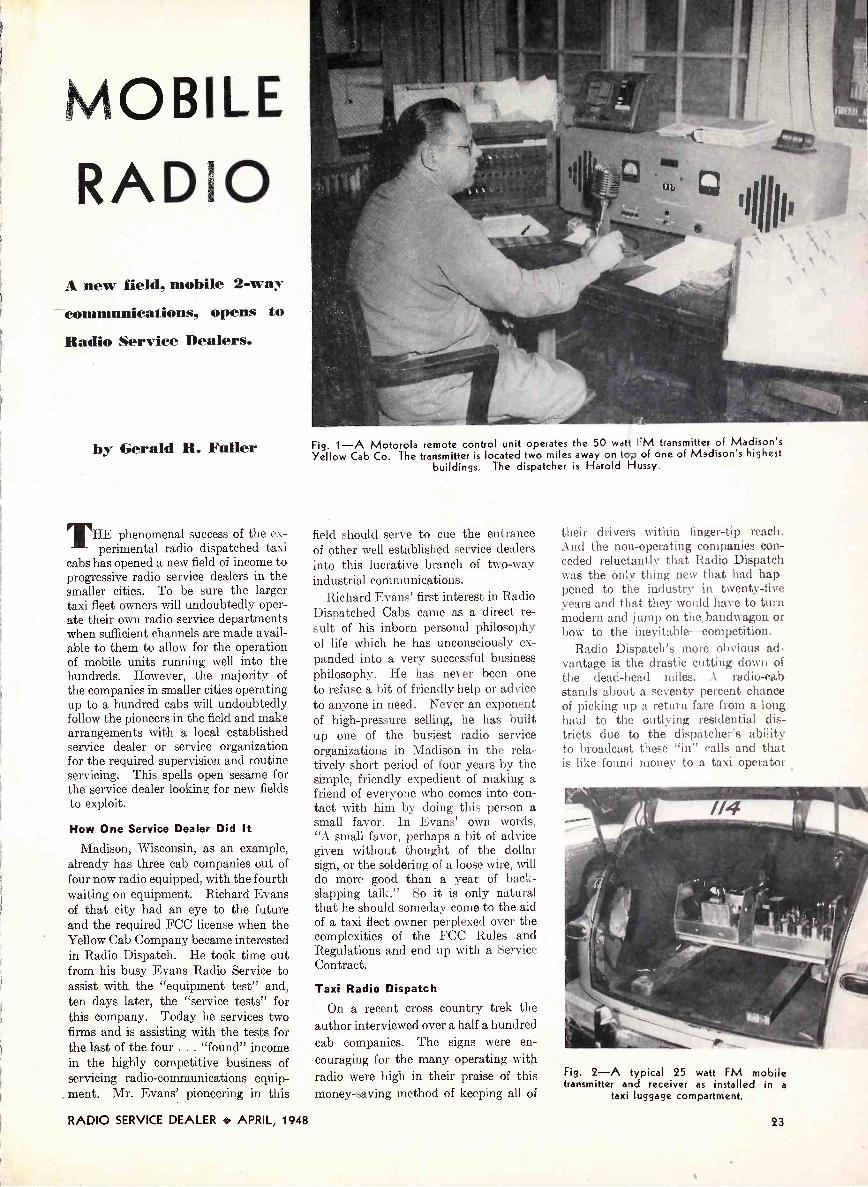
MOBILE
RADIOA new field. mobil 2-wstcommunications, opens to
Radio Service Dealers.
by Gerald R. Fuller
THE phenomenal success of the ex-perimental radio dispatched taxi
cabs has opened a new field of income toprogressive radio service dealers in thesmaller cities. To be sure the largertaxi fleet owners will undoubtedly oper-ate their own radio service departmentswhen sufficient channels are made avail-able to them to allow for the operationof mobile units running well into thehundreds. However, the majority ofthe companies in smaller cities operatingup to a hundred cabs will undoubtedlyfollow the pioneers in the field and makearrangements with a local establishedservice dealer or service organizationfor the required supervision and routineservicing. This spells open sesame forthe service dealer looking for new fieldsto exploit.
How One Service Dealer Did It
Madison, Wisconsin, as an example,already has three cab companies out offour now radio equipped, with the fourthwaiting on equipment. Richard Evansof that city had an eye to the futureand the required FCC license when theYellow Cab Company became interestedin Radio Dispatch. He took time outfrom his busy Evans Radio Service toassist with the "equipment test" and,ten days later, the "service tests" forthis company. Today he services twofirms and is assisting with the tests forthe last of the four . . . "found" incomein the highly competitive business ofservicing radio -communications equip-
. ment. Mr. Evans' pioneering in this
Fig. 1-A Motorola remote control unit operates the 50 watt FM transmitter of Madison'sYellow Cab Co. The transmitter is located two miles away on top of one of Madison's highest
buildings. The dispatcher is Harold Hussy.
field should serve to cue the entranceof other well established service dealersinto this lucrative branch of two-wayindustrial communications.
Richard Evans' first interest in RadioDispatched Cabs came as a direct re-sult of his inborn personal philosophyof life which he has unconsciously ex-panded into a very successful businessphilosophy. He has never been oneto refuse a bit of friendly help or adviceto anyone in need. Never an exponentof high-pressure selling, he has builtup one of the busiest radio serviceorganizations in Madison in the rela-tively short period of four years by thesimple, friendly expedient of making afriend of everyone who comes into con-tact with him by doing this person asmall favor. In Evans' own words,"A small favor, perhaps a bit of advicegiven without thought of the dollarsign, or the soldering of a loose wire, willdo more good than a year of back-slapping talk." So it is only naturalthat he should someday come to the aidof a taxi fleet owner perplexed over thecomplexities of the FCC Rules andRegulations and end up with a ServiceContract.
Taxi Radio Dispatch
On a recent cross country trek theauthor interviewed over a half a hundredcab companies. The signs were en-couraging for the many operating withradio were high in their praise of thismoney -saving method of keeping all of
their drivers within finger-tip reach.And the non -operating companies con-ceded reluctantly that Radio Dispatchwas the only thing new that had hap-pened to the industry in twenty-fiveyears and that they would have to turnmodern and jump on the bandwagon orbow to the inevitable-competition.
Radio Dispatch's more obvious ad-vantage is the drastic cutting down ofthe dead -head miles. A radio -cabstands about a seventy percent chanceof picking up a return fare from a longhaul to the outlying residential dis-tricts due to the dispatcher's abilityto broadcast these "in" calls and thatis like found money to a taxi operator
Fig. 2-A typical 25 watt FM mobiletransmitter and receiver as installed in a
taxi luggage compartment.
RADIO SERVICE DEALER + APRIL, 1948 23

Fig. 3-Mr. R. K. Evans, of Evan's radio Service, Madison, Wisc., sets up mobile unit in theeasy -to -construct mock-up he built in his shop to facilitate the servicing of mobile communica-tions units. Technicians planning to handle mobile equipment repairs will find such a mock-up
makes for faster, easier repairing.
plagued with the increasingly high costof gasoline and maintenance.
Another advantage of equal impor-tance in the faster, better service offeredby Radio Dispatch. Where, in thepast, a customer requesting a taxiusually had to wait from ten to fifteenminutes he now replaces the receiverand in many cases glances out the win-dow to see his cab pulling over to thecurb. The public has always beenquick to recognize efficient service.So Radio Dispatch will soon be anAmerican institution along side self-service super markets and the gasstation attendant who cleans your wind-shield.
There are two factors holding up thegeneral landslide at this writing. One,the slowness of equipment deliveries,speaks for itself. However, the bugshave been worked out of present-dayequipment and manufacturers are prom-ising better designed, cheaper equip-ment for the future. At the presentthere are only two channels of theUrban Mobile Service's 152-162 mcband assigned to taxis. This is adefinite bottleneck.
Other Type 2 -way Radio Users
The Urban Mobile Service band wasset aside to afford two-way communi-cation between fixed stations and suchmobile units as pick-up and deliverytrucks, doctor's vehicles, armored cars,railway express trucks, oil trucks, taxicabs, boats in adjacent harbors and aone-way signaling service to indicateto the vehicle operator that he should
call his home office. However, taxicabs have been the only ones makingextensive use of this band to date.
Radio Dispatch utilizes a duplex cir-cuit with 152.27 mc assigned to thefixed land station and 157.53 mc givento the mobile units. All cab companieshave to share these frequencies and incities having more than one radio -cabcompany the channel is unable to handleall of the traffic. However, the FCCheld a hearing on the subject and, dueto the success of Radio Dispatch, addi-tional channels are expected. Enough,
it is hoped, to handle the traffic of the1000-1500 radio -cabs planned for suchcities as New York, Chicago, SanFrancisco and Los Angeles.
It is the practice of the majority ofthe equipment manufacturers to initiatethe procurement of the station licenseafter selling the cab company, supervisethe installation of equipment and assistthe buyer in obtaining the services of acompetent radioman. The past recordhas shown that there is a great varia-tion in the extent of the supervision,leaving the field open to interestedlocal radiomen. For, although eachmanufacturer is well represented withfield engineers, the cab company has toemploy a full time service engineer incompliance with the FCC Rules andRegulations governing this type ofstation with the service engineer "oncall" rather than on duty. Thereforethe cab companies prefer to farm out theresponsibility to an established serviceorganization, providing the FCC licenserequirements are met, rather than go tothe greater expense of adding anotherman to their payroll. In the largercities, of course, where the operatingcompanies will have several hundredunits to service it probably will be totheir advantage to set up their ownservice organizations.
In brief, the licensing schedule followsthis pattern: The taxi company ap-plies for a station construction permitin the same manner as the larger broad-cast stations. Then within a period oftime the equipment is ordered, deliveredand installed. Within two days of thedate the transmitter is scheduled to befired up the Service Engineer must fileapplication for the Equipment Test. This
Fig. 4-(Top left), Motorola PA -8026 transmitter chassis with DC power supply; (top right)same transmitter with AC power supply; (bottom left) Motorola 8119 receiver chassis with DC
power supply; (bottom right) same receiver with AC supply.
24 RADIO SERVICE DEALER 4, APRIL, 1948

CONTROL CABLE-
MICROPHONE -
CONTROL HEAD
FUSE BLOCK -
ANTENNA-+
7
DETAIL NO 63E475113
-POWER CABLE
ANTENNA CABLE
Fig. 5-Installation of Radiotelephone equipment in the average automobile is relatively simple.
CABLE CLAMPS
t -MOTOROLADISPATCHER
period of actually checking the equip-ment and getting on the air is limited toten days. However, before the eighthday the FCC must be notified of the be-ginning of the Service Test and applica-tion made for the license. The ServiceTest has a thirty day limit, with exten-sions of the time limit possible. And thetime is devoted to checks for interferencecoverage and serviceability of theequipment. With the issuance of thelicense the duties of the Service Engi-neer become rather routine, consistingmainly of maintenance, orienting thetaxi company's dispatcher and cabdrivers to the ways of two-way radiocommunication, and seeing to it thatthe proper logs are maintained.
The Use of "Q" CallsIt may be that the Service Engineer
will have to familiarize himself with thepopularily adopted communication callsfor Radio Dispatch which differ some-what from the "Q" calls of the com-mercial communications networks andthe Ham Operators. Most taxi com-panies use the following numericalcode:
10-1 Standby10-2 Yes10-3 No10-4 Acknowledge (d)
Fig. 6-New FM radiotelephone dispatcherin trunk compartment of a Doctor's car.Note compactness, small degree of space
used.
Fig. 8-View of FM radiotelephone dis-patch unit withdrawn from its regular case.
10-5 Location?10-6 Passengers?10-7 Out10-8 In10-9 Repeat10-10 Destination10-11 Time signal10-12 Empty10-13 EmergencyThe troubles that the newly indoc-
trinated Service Engineer will run intoare the usual routine component partfailures, flat tubes, relay and powersupply failures. The majority of theequipment installed at the present wasdesigned by engineers with policecommunications background. This hasresulted in rather efficient transmittersand receivers on the whole but it isnoted that the control circuits are notstanding up under the heavy load ofRadio Dispatch. A taxi driver uses
TO
CONTROLHEAD
Fig.
FUSEBLOCK 30 AMR FUSE
FROM TRANSMITTER
GENERATOR
9-CI o se
GROUNDBRAID
up of
AMP. FUSE(ar ID 41,
TRW
fuse -block
iF
wiring.
GROUND BRAIDTO CAR FRAME
his unit about three to four times morethan the average police officer.
With one known exception the equip-ment is narrow hand FM. The ex-ception is One firm reconverting surplusArmy SCR 522s to taxi use.
Test Equipment NeededA considerable sum of money could
easily be tied up in VHF test equip-ment. However, a practical servicedealer could get by readily with theordinary test equipment his shop alreadycontains plus the tuning meter normallysupplied with the units by the manu-facturer. A permanent mock-up con-sisting of a hi -amperage six volt powersource plus the junction and controlboxes and the various inter -connectingcables perculiar to the make of equip-ment he will service should prove in-valuable and can be constructed withthe minimum outlay of cash. Additionscan be added by imaginative individualsto meet personal whims and tastes.
To avert the possibilities of the leanyears of the "30's" being repeatedafter the present boom subsides theradio serviceman -dealer of today shouldgive serious thought to branching outinto all phases of electronics, particu-larly selling and servicing radio -com-munications systems.
Fig. 7-Two-way radiotelephone receiver,(left), and transmitter, (right), housed inspace over rear left wheel of modern Grey-
hound bus.
RADIO SERVICE DEALER 4. APRIL, 1948 25

CIRCUIT COURTAirline Model 74WG-2505A
An interesting variation in the wayof convertor stages is to be found in theAirline set illustrated. A miniaturetype of dual triode, 6J6, is employed.This tube has a common cathode.
Output of the 6BA6 tuned r -f stage(used only on the FM band) is capaci-tively coupled to the tuned grid coil ofthe mixer section of the 6J6. Signalbias is developed across a .1 meg. leak.
Oscillator voltage appearing on themixer plate is by-passed by a 47 µµfcondenser. A series choke in the platelead to the first 10.7 mc. i-f transformeraids in the action.
The oscillator portion of the tube isbiased by the drop developed across the10K -ohm leak. The grid is effectivelyat ground potential for signal voltage.The cathode is tapped part way up onthe coil element of the tuned circuit.Plate voltage is supplied to the oscil-lator portion via an r -f choke. Theplate is coupled nearer the top of thecoil than the cathode, by a 47 i.Lauf unit.The conditions for generation of oscilla-tions thus being provided, and couplingto the mixer section obtaining by virtueof the common cathode element, efficientperformance is possible with a minimumof components and complication.
Hoffman Model 8503
The Hoffman model B503 providesseveral interesting circuit functions.A block diagram is shown to simplifyour explanation of it.
The instrument provides for radioreception or recording, record playbackor microphone recording. Broadcastand two short wave bands are available.
The r -f i-f section is conventional,using 6SK7 tubes as amplifiers and a6SA7 as a convertor. A 6SQ7 tubeperforms the functions of detector,AVC rectifier and first audio amplifierfor radio. The following stage, usinga 6J5 triode, operates as a tone com-pensating network. Separate bass andtreble boost or attenuation are pro-vided. It is interesting to note thatall compensation is switched out whenthe recording feature is switched in.This insures maximum fidelity im-pressed on the record, to be compen-sated as reproduced.
The next stage operates as a phaseinvertor and feeds the push-pull 6V6output tubes. One 6V6 grid is fed fromthe 6J5 invertor plate-the other fromthe cathode.
Output of the 6V6 stage can be
100 MMFD.
66A6F. M.R.F.
100MMFD.
47 MMFD.
10K
500'MMFD.
0.1MEG.
15K
6J6- CONV. Ch
MMFD.
111
47MMFD.
0MM50D.=
4 4
18K
8+
Converter stages of Airline
switched to either the speaker or thecutter. For recording from a micro-phone, two additional audio stages areinserted to bring the level up to anormal value. A 6SJ7 pentode and6SQ7 triode section provide the gain.Output of the 6SQ7 feeds the grid of the6J5 invertor. A gain control for themike stages is included. Radio andmike outputs can be mixed for re-cording.
The diodes of the 6SQ7 in the mikeamplifier are used to rectify a portionof the 6V6 output and the voltage thusdeveloped causes a 6U5 eye tube toindicate the volume level. This featurepermits accurate setting of gain forbest record cutting.
Output of the phone pickup is con-nected to the triode elements of the6SQ7 first audio stage.
Emerson Model 540A
In the Emerson 540A receiver, usingminiature tubes throughout, is an un-usual mixer -oscillator circuit. The tubeemployed is a 12BE6. Variable in-ductance tuning is used, with gaugedsliding cores.
One variation from the normal is theuse of a loop tapped across a portion ofthe mixer grid coil. This permitspickup and coil tuning without mis-match due to capacitance coupling.
model 74WG-2505A
Note that the inductance is shunted bya 100 ,upf fixed unit and a timmercondenser.
The oscillator circuit is of the Col-pitts type rather than the Hartleyusually employed. The cathode is
100MMFD.
12BE6
300 MMFD.
=1000 MMFD.
-L-I-0.1 EQUIVALENTMFD.
I.F T.
El+
AVG
OSC.
300 110MMFD. MMFD.
1000 22KMMFO.
_4700OHMS
4700OHMS,
Oscillator-mixer circuit of Emersonmodel 540A
grounded directly instead of beingtapped up on the coil. One end of thecoil connects to the oscillator gridthrough 110 µµf, while the grid returnsto ground via 22K ohms. The second
[Continued on page 841
6SK7R F.
6SA7CONY.
5U4GRECT.
6SK7I.F.
Phono 0
MIKE
6SQ7DET.AVCA.F.
6SJ7MIKEAMP.
TONECONTROL
o-Closed forrecording
6SQ7A.F.RECT.
6,15PHASE
INV.
6U5EYEI NO.
6V6A.F.
OUTPUT
6V6A.F.
OUTPUT
Sp k'r
Cutter
Block diagram of Hoffman model 8503
26 RADIO SERVICE DEALER APRIL, 1948

SHOP NOTESWrite up any "tricks -of -the -trade" in radio servicing that you have discovered.We pay from $1 to $5 for such previously unpublished "SHOP NOTES"
found acceptable. Send your data to "Shop Notes Editor".
Arvin Model 665-Eliminating Humand Improving Tone Quality
To eliminate modulation hum f re-quently encountered in this 6 tube a.c.&ono -combination, replace the 1 megresistor in the grid circuit of the con-vertor tube, (formerly R13) in manu-facturer's schematic) with a 100,000.ohm resistor shown in the accompanyingillustration as R15.
As illustrated R15 is connected fromgrid to floating ground, contrasted withR13 which was connected from grid toAVC line.
This set's tone quality may be im-proved by replacing condensers C5,.0005 ,uf across the volume control
C14, .0002f Af, and C7, .002 pcf on thetone control with C13, .005 µf.
Submitted by Albert Loisch, Darby, Pa.
Trick for Replacing Speaker ConesWhen making speaker cone installa-
tions or repairs to same, a half -dozenspring -type clothespins can be helpful.Use them around the speaker rim tohold the cone edges down while thecement dries.
Submitted by Richard Preston, Oxford,N. Y.
Records and Needles
Webster has come up with a fewrecord maintenance hints, and needlefacts which are well worth the service-man's consideration. They, also maywell be incorporated on the back of asuitable card for advertising purposes.Here they are:
Records1. Do not buy (or use)* warped
records, or those showing obvious wear.2. Keep records in their envelopes
and albums, preferably laid flat to pre-vent warping.
3. Do not keep near heat as this willwarp the records.
4. Keep records clean with a softbrush (do not use cloth)* to avoidgrinding dust and lint into the grooves.
5. Do not leave records on posts onconventional stack up type or recordchanger. The limited support, plusheat of the changer compartment, willsurely cause warping.
Note:* Editor's addition
** These needles give satisfactoryservice up to ten playings.
6. Use a good needle and replace whenwear becomes apparent.
Needles
So many different types of phono-graph needles are on the market thatthere is often confusion as to which ismost suitable. The following brief sum-mary lists the different types and setsforth the qualifications of each.
SteelThese are full tone, half tone and
various odd shapes made of steel only.Usually give greatest volume. Should notbe used to play more than one record.**Standard types give greatest high fre-quency response with resultant highernoise, scratch, and hiss level. Pointswear rapidly, depositing material ingrooves and damaging records.
Chrome PointThese are steel needles with chrome
plating and have about the same quali-fications as a full tone steel needle, ex-cept that the chrome plating greatlyincreases the life. May be used fortwenty-five to fifty plays, depending onthe pick-up pressure.
Bamboo, Cactus, Thorn, Etc.These are used primarily to reduce
high frequency response, noise andrecord wear. Distortion and low qualityare usually apparent. Unsuitable forrecord changers.
Metal Alloy PointsCome in many shapes and sizes and
may be used for 1,000 to 5,000 playswithout change. Properly alloyedpoints polish to a high degree, increas-ing record life. Should be left in pick-up undisturbed as point wears to fitrecord groove and changing may resultin severe record damage. Recommendedfor record changers.
SapphiresThese needles have a correspondingly
longer life. Same precautions againstdropping and changing position shouldbe observed. Recommended for changersand wide range reproduction.
Antenna ConnectionsShould the occasion arise where it
becomes necessary to replace the con-nections to antennas it is necessary tosee that the flat twin parallel con-
ductor is not twisted. The rear parallelconductor should be connected to therear terminal screw on each loop an-tenna. The front parallel conductorshould be connected to the frontterminal screw on each loop antenna.
Substituting a 42 for 6B5In some of the older models of
Crosleys and Beverlys or any setusing the unobtainable 6B5 tube in theoutput stage, it is possible, with onlya slight change, to substitute a 42.
Disregarding the complicated in-ternal connections of the 6B5, a look atthe socket connections will show thatit is all ready for a 42 except for thegrid bias. Heater connections go onpins 1 and 6. Number 2 pin is theplate, No. 3 pin the screen grid, No. 4pin the control grid, and No. 5 pin thecathode. In the Crosley model 515it is only necessary to remove thegrounded cathode and insert a 300400ohm 5 -watt resistor by-passed by a 10Atf 50 volt condenser.
Since sets using the 6B5 usuallyrequire a driver tube as the 76, it willbe conventionally coupled to the follow-ing grid. The only caution is to makesure of the bias on the 42.
Contributed by R. S. Thompson, Spring-field, Mass.
Philco_ "Mystery" Set-Failure toTune
Philco model 40-216 "Mystery" setssometimes fail to respond to the remotecontrol unit when a change of stationor volume is desired. If you dial astation or try to increase volume andthe automatic mechanism just chattersbut does not function properly, checkthe 16 µf 200 volt electrolytic capacitorNo. 95 (per Philco's schematic), whichis in series with resistor No. 94 acrossrelay solenoids. Conds. No. 95 hasprobably lost its capacity.
Submitted by F. A. Rand, Winthrop,Maine.
Sentinel 286-PR-Weak ReceptionWhen reception is either mushy or
weak, nine times out of ten the troubleis due to an open 4.7 meg. Yi watt Bplus dropping resistor in grid No. 2 ofthe 1S5 tube.
Submitted by Pedro S. Trueba, SanBenito, Tex.
RADIO SERVICE DEALER APRIL, 1948 27

NEW PRODUCTSPrecision Series 85
A new High Sensitivity Test Set hasbeen announced by Precision Appara-tus Company, Inc., 92-27 HoraceHarding Blvd., Elmhurst, L. I., N. Y.
The Series 85 is bakelite cased, light-weight, portable and compact. Af-fording a sensitivity of 20,000 ohmsper volt D.C. and 1,000 ohms per voltA.C.; 34 self-contained ranged areprovided to 6,000 volts, 120 micro-amperes, 12 amperes, +70 DB and 60
megohms. It has a 4-5/8" wide angle50 microampere meter with 2 -colorscale -plate and large easy -readingnumerals. Panel is of heavy gauge,anodized etched aluminum. Unitsupplied complete with self-containedohmmeter batteries and test leads.
Ranges: Voltage Ranges: 0-3-12-60-300-1200-6000 volts A.C. and D.C.Current Ranges: 0-120 microamps,0-1.2-12-120 MA. 0-1.2-12 AmperesD.C. Resistance Ranges: 0-6000ohms (35 ohms at center scale) 0-600K-6 Meg -60 Alegohms. DecibelRanges: From -26 to +70 DB.
New RCA Crystal PhonoReplacement
A new Silent Sapphire CrystalPickup" vv hich may be used as a re-placement for any of 70 differentcrystals employed in the pickup armsof a wide variety of different makesand models of phonographs, is nowbeing marketed by the RenewalSales Section of the RCA Tube De-partment.
New Webster -Chicago RecorderA new wire recorder, especially
designed for easy connection to exist-ing amplifier circuits, is announced
by IA ebst er-t :hicago Corporation.The new unit, Model 78, utilizes
push-button controls for greater flexi-bility of operation in any of four"record" or "listen" positions. Itconsists of a wire transporting mech-anism, a pre -amplifier, interstageamplifier, oscillator and built-in powersupply. Accurately calibrated re-cording level meter assures correctrecording volume. The Model 78 ismounted in an attractive metal case11 3....8" x 11" x 5 5.8". List price willbe $153, east of the Rockies. Formore information contact: S. T. Sea-man, Webster -Chicago Corp., 5610 W.Bloomingdale Ave., Chicago 39, III.
Plastic Expanding Screw Anchor"Hi" plastic screw anchors are
offered by Holub Industries, Inc., box409, DeKalb Ave., Sycamore, Ill.These units, which come in all sizesfor screws sized 5 through 20 aresimply inserted in the hole and as the
1
screw is driven home it automaticallylocks itself in. Ideal for use in con-crete, plaster, and similar instanceswhere it would be otherwise impos-sible to obtain a strong anchorageunder normal procedure. Presentday antenna installations are typicalcases where such anchors fill a need.For literature write to the manu-facturer. The anchors are very inex-pensive and should be in every radioserviceman's tool kit.
Converters for TV Sets in DC AreasA long -needed line of converters
that permits operating TV sets, wirerecorders and other office appliancesin D.C. areas is put on the market byElectronic Laboratories, Inc., Indian-apolis, Ind. The two new units nowavailable are:
MODEL 110R15INPUT: 110 volt DC (Commercial
power line).OUTPUT: 110 volt AC 60 cycles.15 to 150 watts at 80-100' e power
factor.VIBRATOR REPLACEMENT:
Model 1315.Filtering: Converter is radio fre-
quency filtered completely for broad-cast, short wave and FM bands.
Regulation: Variation of voltage
over output power range is so slightthat no external regulation controlis necessary' .
Dintensilm$: 12' long. 613" wide.71, high.
it eight: 15 pounds.Finish: Ilanuuered dark blue baked
enamel with chrome handle.Starting: kutostart u ith conneetion
of load.*Fuse: 5 ampere 3 AC, type , spare
prov ided 1.
NIOHE1, 1101430INPUT: 110 volt DC Commercial
power line,.OUTPUT: 30 to 300 watts at 80-
100' , power factor.VIBRATOR EPL A t: EMENT:
\lode! 3051.Filtering: Converter is radio fre-
quency filtered completely for broad-cast, short wave and FAI bands.
React/Wiwi: Variation of voltage overoutput power range is so slight thatno external regulation control isnecessary'.
Dimensions: 18" long, 8." vi Me. 9"high.
Weight: 55 pounds.Finish: I lammered dark blue baked
enamel..% t os I art vs ith connect
of load.*Fuse: 5 ampere 3 AG type I spare
provided ).*AUTOST pm ides remote oiiera-
thin of \ vrtrus eliminating wiring andinstallation \ ides illStallt 21110011S,starting -appliauces .Tel;ite just HS N1 IWOCOLIlierh'd to 110 volt AC hut..
New Astatic Crystal MikeDescribed as the N civet Voice"
Beauty, a new, convertible t:spe Crs-tal Microphone has just been intro-duced by The Astatic Corporation,Conneaut, Ohio. Made with a de-tachable "quick -lock" base, this mi-crophone may be used as a hand ordesk mike or mounted on floor stand.
It is made with bright chronic grille,gold finish housing and handle, anddark brown baked enamel base.
It is supplied in two models: No.200, with smooth, even frequencyresponse characteristics from 30 to10,000 c.p.s. No. 241, with similarrange but with rising characteristicsbetween 1500 and 5500 c.p.s. for addedbrilliance in the speech range. Eithermodel supplied with or without switchas illustrated.
New RecorderA new home recording unit with
professional feature. has been an-( poge ,;
28 RADIO SERVICE DEALER APRIL, 1948

The NO 0010" 61V
is stout nswer
"iaomical,po
'tubea4 Satter'
Testing
to Ec.
612-C (illustrated). In modernchrome -trimmed, Counter typecabinet. Dull black ripple finishon heavy gauge steel. 16 x 131/3x 7", sloping to 3" at front.
Complete: - $63.95612-P-In hardwood, Portablecase with tool compartment. Size12 x 13 x 6" Complete: - $61.95
612-MCP-Open style Metal CasePortable, fine dull black ripplefinish on heavy gauge steel.Size 101/2 x 12 x 6''
Complete: - $59.95612-PM-In standard size PanelMount 121/4 x-19" with dust cover.For rack cabinet or wall mount-ing. Complete: - $61.95
* Positive Free -Point Tube Testing
PLUS * Highest Practical Obsolescence Insurance
PLUS * Utmost Simplicity of Operation
PLUS * "Precision" Quality and Workmanship
PLUS * Moderate Cost ... Impressive Design
The new Series 612 is a modern, free -point,lever -operated Cathode Conductance TubeTester representing the culmination of extendedand intensive development in the field of moderntube checking requirements. It answers the ever-present need for positive tube testing resultsat moderate cost, with full conformity to "Pre-cision's" high standards of workmanship, perform-ance and quality components.
The new "600" line affords tube testing para-meters based upon the time -proven emission test-ing principles as recommended by both tubemanufacturers and R.M.A.; plus innumerable cir-cuit features which render it incomparableamongst instruments in its category.
TUBE AND BATTERY TESTING FEATURES* Tests all modern tube types including
7 pin Acorns, button 7 and Noval 9pin types, dual -capped H.F. tubes, FMand TV amplifiers, etc.
* Filament voltages from 3/4 to 117 volts.* Absolute Free -Point 10 element lever
selection for both short and merit tests.* 41/z" wide vision meter. 2°/0 Accuracy.* Dual HI -LO short -check sensitivity.
* Individual Tests of Multi -SectionTubes including tuning indicators, gasrectifiers, oscillator -converters, etc.
* Ballast Unit Tests.* Micro -Line adjustment -
continuously variable.* Pilot and signal light tests.* Noise and Condenser test pin jacks.
SERIES 620TUBE, BATTERY AND SET TESTERRANGES TO 3000 VOLTS, 12 AMPERES, + 641:1B, 10 MEGOHMS
A COMPLETE, PORTABLE, SERVICE LABORATORYproviding every essential feature for gen-eral purpose test and check of modernradio and electronic equipment.
Incorporates the identical tube test cir-cuit and battery testing features of theSeries 612, (described above) PLUS a com-plete A.C.-D.C. Multi -Range Circuit Teslerof 1000 ohms per volt sensitivity.
CIRCUIT TESTING FEATURES
'e 5 A.C. D.C.-Output Voltage Ranges: to 3000 volts.'e 5 D.C. Current Ranges: to 12 Amperes
3 Resistance Ranges: self-contained: to 10 Megohms.* 5 Decibel Ranges from -12 to +64 DB.
Full rotary Range and Function Selection.e 2 pin jacks serve all standard ranges.* I% Wire -wound and Metallized Resistors.w 400 microampere 45/8, Meter. 2% accuracy.e All Circuits Insulated from power line.
The Series 620 is available in the samefour model types as described for theseries 612 (above)
620-C - Counter Cabinet__ Net Price $84.30620-P - Portable Case. Net Price $82.30620-MCP-Metal Case Port.. Net Price $80.30620 -PM - Panel Mount. Net Price $82.30
* Dynamic "under -load" test for all pop-ular radio A, B, and C dry batteries.
* Built-in, brass geared roll chart.* Anodized, deep -etched,
heavy gauge aluminum panel.* Panel -mounted Fuse extractor Post.* Telephone type cabled wiring using
plastic -insulated moisture resistanthook-up wire.
SEEthese new "Precision" Test In -struments now on display at all
leading radio parts and equipmentdistributors, or write directly for thePrecision 1948 catalog describing thefull Precision line of quality Elec-tronic Test Instruments.
PRECISIONPRECISIONTEST EQUIPMENT APPARATUS COMPANY INC.
92-27c HORACE HARDING BOULEVARDELMHURST 8, NEW YORK
RADIO SERVICE DEALER APRIL, 1948 29

nounced by the Universal Micro-phone Company.
Called the Universal RC RecordingChassis, this new unit is said to havethese features:
(1) Recording extremely close tan-gency.
(2) Patented pantographic move-ment makes possible equallyspaced cutting over the entirerecord.Groove depth adjustment isvisible and adjustment can bemade in recording position.
(4) Pantographic action keepsguide shoe at correct angle inlead screw thread-records in-side to outside.A lift lever at side of headallows the operator to locatethe stylus in the exact groovelocation after the lead screwhas been engaged.
(6) New RC Recording Chassisrecords music and voice atcommercial levels and loud-ness.Recording head is automati-cally lifted at the end of a 10"record.
Using a 10" turntable the heavyduty, 110 volt, 60 cycle 78 RPM motoris complete with crystal pick-up toplay back 12" records. Further in-formation can be had by writing toUniversal . Microphone Company,Centinela at Warren Lane, Inglewood,California.
Compact Servicettes
(3)
(5)
(7)
Designed to accommodate severalessential service instruments, whichcan be removed for bench operation.In addition, compartments are pro-vided for test leads and tools.
Servicette Model 4410-Pocket mul-titester Model 449A with pocketsignal generator Model 710, plus testleads, output lead, and carrying case.
Servicette Model 4420-same asModel 4410 except that FM pocketsignal generator Model 720 is includedinstead of Model 710.
For further information, write to
BOOK REVIEWS6th Edition Mallory Encyclopedia
The 6th Edition of the Mallory RadioService Encyclopedia has been an-nounced by P. R. Mallory & Co., Inc.,Indianapolis, Ind.
The latest edition, which provideshelpful service information on all pre-war and postwar receivers in onevolume, contains 25% more listingsthan the 5th Edition.
The Encyclopedia includes detailedreplacement information on volume andtone controls, capacitors, and vibrators. . . circuit information, service hints,installation Rotes, I.F. peaks, tubecomplements and number of tubes . . .
and in addition, shows a reference toRider's Manual, volume and page
for each receiver. The 6thEdition will be available at a net priceof $2.00 on April 1st through all Mallorydistributors.
FM Transmission and Reception,by John F. Rider and Seymour D. Uslan;Published by John F. Rider Pub-lisher, Inc.
An up-to-the-minute 416 -page bookcovers the principles underlying theoperation of the complete FM trans-mitter and receiver. The first sectiondiscusses both the narrow -band and'wide -band transmitters manufacturedtoday for service in television-in ham,aviation, marine, police, point-to-point,and mobile radio communication sys-tems. Both direct and indirect FMtransmitter theory is explained as wellas a complete coverage of both trans-
mitting and receiving antennasThe second section of the book ex-
plains each stage of an FM receiver,comparing them with their counter-parts in AM sets, and with specialattention being given to the fourdifferent types of FM detectors as wellas the FM tuners that are marketedtoday. In the chapter on alignmentof receivers, both the meter method,visual method and a combination of thetwo are thoroughly discussed. Suchservicing problems as relocation ofantennas, image response, noise andoscillator troubles, cathode lead in-ductances, etc. are contained in the lastchapter. A comprehensive bibliogra-phy and index are included.
"FM Transmission and Reception"is now available at jobbers in eitherpaper or cloth binding.
Broadcast Operators Handbook,
by Harold E. Ennes, published by JohnF. Rider Publisher, Inc.
This 288 -page book fills the gap inthe literature covering the engineeringdevelopment of broadcast equipmentand its practical operation. The firstfour parts of the Handbook coveroperating practice in control rooms, themaster control, remote controls, and thetransmitter. The fifth and sixth sec-tions discuss technical data for operatorsand technicians, including comprehen-sive preventive maintenance instruc-tions; operational data for transmittermeters and indicators are included inthe appendix, which is followed by abibliography and index.
"Broadcast Operators Handbook,"which is now available at jobbers, iswritten in operators' language. It isintended not only for the newcomerto the field, but for the old timers aswell, who will find many ideas in it thatwill furnish new and refreshing slantson many phases of putting programs onthe air in the best possible way.
Radio City Products Company, Inc.,152 West 25th Street, New York 1,N. Y.
Oak Ridge Develops Collar ClampOak Ridge Antennas, manufac-
turers of the "Rig -Fast" line, an-nounces a new all aluminum collarclamp which holds antenna and
reflector elements in place on themast or cross arm stronger and morepermanently. The new clamps as-sure quick, accurate alignment andprevent the elements from twistingor slipping out of position. Thismeans the elements last longer andthe receiver always gets the strongestpossible signal.
ADDRESS CHANGES . . .Subscribers to RADIO SERVICE DEALER shouldnotify our Circulation Dept. at least 3 weeks in ad-vance regarding any change in address. We cannotduplicate copies of RADIO SERVICE DEALERsent to your old address. Old and new addressesMUST be given.
Circulation Dept.RADIO SERVICE DEALER
342 Madison Ave., New York 17, N. Y.
30 RADIO SERVICE DEALER APRIL, 1948
TO YOUNG WORKING GIRLS -WHETHER IN LOVE OR NOT
When a young girl goes to work, she isapt to look on her job pretty much as afill-in between maturity and marriage.
Whether in love or not, she's confidentthat a handsome breadwinner will comealong ... to provide her with a nice com-bination of bliss and security.
"So why," she may ask, "should I savemoney out of what I make ?"
There are a number of reasons why-all good ones. For example:
(A) The right man might not happenalong for some time.
(B) He might not be able to provideher with quite all the little luxuries a
young married woman would like to have.
(C) Having money of her own is a com-fort to any woman, no matter how success-fully she marries.
So we urge all working girls-if you'renot buying U. S. Savings Bonds on a Pay-roll Plan, get started now.
It's an easy, painless, and automaticway to set aside money for the future. Inten years, you'll get back $4 for every $3you put in-and a welcome $4 you'llfind it!
Remember, girls-having money of yourown may not make you more attractive,but it certainly won't make you less!
ES.
not 011 pay-rolls, but who have
aabank,
account inshould buy theirBonds on the simpleautomatic
Bond -A'Month Plan.
WOrrien
AUTOMATIC SAVING IS SURE SAVING - U.S. SAVINGS BONDS
Contributed by this magazine in co-operationwith the Magazine Publishers of America as a public service.
RADIO SERVICE DEALER + APRIL, 1948 31

LABORATORIES, INC.,
The outstanding lineof converters withnew engineering...new design
for TELEVISIONWire Recorders . . .
Radio Phonograph Combination . . . SmallPower Tools (1/10th H.P. maximum) . . .
Public Address Systems . . . Amplifiers . . .
Communication Receivers and Transmitters. . . Small Appliances (mixers, Vacuumcleaners, etc.) . . . Laboratory Test Equip-ment . . . Sound On Film Amplifiers . . .
Intercommunication Systems . . . MovieProjector Motors . . . Razors . . . Otherelectrical devices.
ATTRACTIVEW PACKAGING,
1. The 110 volt and 32 volt con.verters are equipped withAUTOSTART . . . the auto-matic start and stop feature.This provides remote opera-tion of converters, eliminatingwiring and installation costs. . . provides instantaneousstarting with no warming up.
2. El Battery Eliminators arethe only units on the marketthat can simulate actual year'round operating conditionsin the radio repair man'sshop. The overload switch isespecially valuable to momen-tarily overload components tobreak down questionable partsand prevent service call backs.
3. E -L Power Supplies are radiofrequency filtered completelyfor broadcast, short wave,F.M.- and TELEVISIONbands.
ELECTRONIC LABORATORIES,INC.==
TRADE FLASHES[ from page 12]
advertising material can lift the illus-trations directly from the proof sheetsfor printing.
Rep. & Distributor AppointmentsRodney Young Co. is now Cincinnati
distributor for U. S. Television Mfg.Co.
Corwin Company now distributesArvin radios and electrical appliancesin the Los Angeles area.
Rowles Sales Co. in San Antonio;Appliance Distributors, Inc. in Louis-ville and Lincoln Sales Corp. in Balti-more now handle the Bendix Radio lineas distributors.
Hyland Elec. Supply Co. of Chicagonow distributes the Sentinel Radio line.
Newell B. Parsons is now manu-facturer's representative for Webster -Chicago in the Chicago and Milwaukeeareas.
J. E. Redmond Supply Co. of Phoenixnow distributes the Packard -Bell line ofradios.
Stromberg-Carlson appoints dis-tributors the following: Mid -AtlanticAppliances of Washington, D. C., andBaltimore for D. C., parts of Virginiaand W. Va.; Graybar Elec. of Syracuseto serve central and western N. Y.;Stubbs Elec. of Portland, Ore. in severalcounties of Oregon and WashingtonState; Graybar Elec. of Cincinnati tocover sections of Indiana and Kentucky.
Seven new distributors are announcedby Stewart -Warner. They are Ander-son -Young Electric Co., Lubbock, Texas;Elcon Products Co., Minneapolis, Minn;A. H. Marshall Co., Inc., Plattsburg,N. Y.; Wilkins Distributing Co., SaltLake City, Utah; Scott Sales Co.,Toledo, Ohio; Graybar Electric Co.,Eugene, Oregon, and Looboyle RefiningCo., Tulsa, Okla. All are exclusivedistributors in their cities. .
Phono Crystal Replacement GuideA new guide to phonograph crystal
replacement, which shows clearly theexact replacement crystal to use in thedifferent models of RCA Victor phono-graphs, has been prepared by the RCATube Department and is now availableto radio servicemen and dealers throughRCA Parts Distributors.
Air King Adds DistributorsAir King Products Co., Inc., Brook-
lyn, N. Y., manufacturers of radios,combinations and wire recorders an-nounced the following distributor ap-pointments:
They are: Mission Radio, San An-tonio, Texas; Whitehead Radio Co.,Columbus 15, Ohio; D. & R. Radio
32 RADIO SERVICE DEALER APRIL, 1948

Supply, Steubenville, Ohio; Eagle SalesCo., Providence, R. I.; A. C. McClurgCo., Chicago, Ill.; Toledo Radio Special-ties, Toledo 2, Ohio; Barno Radio Co.,McKeesport, Pa.; Thompson RadioSupplies, Zanesville, Ohio; Hicks RadioSupply, West Va.; Fall Radio SupplyCo., Canton, Ohio; Electronic Dis-tributors, Lexington, Kentucky, A. W.Mayer Company, Boston 15, Mass.
Illinois Cond. Catalog Supplement
Illinois Condenser Co., 1616 N.Throop Street, Chicago 22, Illinoisannounces a supplement to their catalog-of September 2, 1947. This supplementlists new additions to the "Illini" lineof Electrolytic Condensers. Includedare types especially designed for use involtage doubling circuits. Also severalnew high voltage, high capacity typesare listed for the first time.
Copies of this supplement may beobtained by writing the company.
New Vol -Control KitThe Han -D -Kit No. 5 just released
by Clarostat Mfg. Co., Inc., 130 ClintonSt., Brooklyn, N. Y. contains 12 of themost popular values of plain, tappedand slip -drive controls, together with aselection of 12 attachable shafts and 4as -a -switches; 6 ballast tubes mostgenerally called for; five Green -ohms or10 -watt wire -wound power resistors;plus a double -ended wrench, authorizedservice plaque, copy of latest catalog,and a registration card calling for afree copy of the new 50c ClarostatService Manual-all packed in a green -finished steel cabinet with hinged coverand entirely free of any advertisingmatter, so that it can be used later as afiling cabinet or handy box. Repre-senting a total value of $30.15, thedealer's net is only $15.07. But themain thing about this kit is that it'sgood to the last item. It contains no"duds."
Shure Introduces New Wire -Re-cording Heads
A new line of wire -recording headshas been announced by Shure Brothers,Inc. of Chicago. The manufacturersstate that the new heads are unusualin the versatility of their mechanicaland electrical adaptations. Recording,play -back, and erasing features havebeen combined into one small compactunit. Mechanical construction also per-mits a variety of shielding and mount-ing arrangements.
Impedances and internal connectionsmay be varied to suit individual needs.Other features are: uniform perform-ance, excellent wear characteristics,reduced hum pickup, and a controlledgroove contour. Complete informa-tion is available to firms writing oncompany letterhead.
A GREATi VigICk FIRST!
NEW...Sensational TRANSVISION Development now offersLARGE -IMAGE DIRECT -VIEW TELEVISION at low cost!
BIGGEST VALUE in TELEVISION!Model 10BL TELEVISION KIT with FMRadio ... Features Beautiful CABINET withBUILT-IN LENS.Gives LARGE 120 Sq. In. Picture
Roto-picture effect: Picture "rotates," givingthe appearance of being in focus and clearlyvisible from every angle! Uses 10" Electro-magnetic Direct -view Picture Tube.Features new -type cabinet with built-in lenswhich magnifies, clarifies and heightens con-trast of the picture. The lens also creates theeffect of apparent rotation of the picture, sothat when the observer moves, the picture stillseems to be in focus and clearly visible fromany angle. MODEL 10BL
ECONOMICAL KIT, EASY TO ASSEMBLE. In point of value, this Television Kit providesthe opportunity of acquiring a LARGE -IMAGE direct -view television set at a VERY LOWPRICE; also very economical from a tube replacement angle. This model is available inKIT FORM, for easy assembly: no:technical knowledge required. Simple step-by-step in-structions are included. Saves as much as 50% over the cost of receivers with similar picturemagnitude.TECHNICAL DATA: Model IOBL uses a 10" Electromagnetic Direct -view Picture Tube; hascomplete F.M. Radio which comes completely factoryLwired; receives all channels in anyarea; supplied complete with antenna and lead-in wire. The LENS is 15" x 11", giving apicture size of approx. 10" x 12" or 120 sq. in.; the highly -styled cabinet measures 26" widex 17" high x 19" deep, available in Mahogany. Walnut, or Blonde finishes.PRICES: Transvision MODEL 10BL Television Kit, with FM, 10" tube, cabinet with built-inlens, antenna, 60 ft. lead-in wire LIST $359.00MODEL 12BL, same as 10BL except that it uses 12" tube, giving picture area of 130 sq.in LIST $389.00
Scoop' New.ally
Designed
MODEL 7BL Television Kit with
Sp eci CABINET with BUILT-IN LENS
Uses 7" Electrostatic Picture Tube Gives 50 square inch picture of superior quality
FEATURES: Though it has a 7" tube. the effect isequivalent to a 10" set because the built-in lensmagnifies the picture. Also picture performanceis superior because the lens clarifies and heightenscontrast of the image. Picture "rotates" ap-parently, as the observer moves, giving the effectof always facing the observer. This is effective to avery wide angle. Pre -tuned for 5 channels.PRICE: Including cabinet with built -In lens,antenna, 60 ft. of lead-in wire. NET 3150.00.
TRANSVISION "SERVICE NOTES"The Key to Successful Television Servicing
Transvision's "Service Notes" is a compilation of confidential Tele-vision Notes and Information, the product of experience with over20,000 television receivers, now made available to the public.The "Service Notes" is a most valuable compilation of instructionsand data on Magnetic and Electrostatic Television Receivers. Thoughcompiled in the course of servicing Transvision Kits, the informationis applicable to any type of television receiver."Service Notes" is complete with photographs and diagrams. Theinformation is worth a small fortune. The cost is low. LIST $2.95.
All prices 5% higher west of Mississippi; all prices fair traded.
For further information see your distributor, or write to:
TRANSVISION, INC. Dept. S.D., NEW ROCHELLE, N. Y.
See TRANSVISION at the PARTS SHOW! There will 'be a SPECIAL TRANSVISIONEXHIBIT from May 10th through the 14th at the SHERMAN HOTEL (Chicago) in theGOVERNOR'S SUITE! Be sure to see the interesting new Transvision Developments in
Television and FM.
RADIO SERVICE DEALER 4 APRIL, 1948 33

SPEAKERSYOUR JOBBER CAN SUPPLY YOU/
Permoflux quality and dependability-the same as suppliedto the major set manufacturers-is your assurance of com-plete customer satisfaction. You'll find Permoflux Speak-ers easy to install and readily available in both PM andElectro-dynamic types. You'll find too, that it pays togive your customers " tops in tone" with a PermofluxReplacement Speaker.
FACTORIES TO SERVE YOU PERm/0\dFLUX FREE BULLETIN
TWO COMPLETE WRITE FOR
PIONEER MANUFACTURERS OF PERMANENT MAGNET DYNAMIC TRANSDUCERS
PERMOFLUX CORPORATION4900 WEST GRAND AVE., CHICAGO 39, ILLINOIS
236 SOUTH VERDUGO ROAD, GLENDALE 5, CALIFORNIA
SERVICE DEALERS
For 8 consecutive years "Radio ServiceDealer- has consistently published moreexclusive and authentic articles on: (1)new radio servicing methods and tech-niques; (2) new test equipment and itsapplications; (3) new and unusual re-ceiver circuits; (4) P -A and sound in-stallation and service methods; (5) FMand Television circuits, installation andservicing techniques; (6) Shop Notes;(7) practical bookkeeping and businessmanagement methods-than any othermonthly magazine purporting to cater toradio technicians.
From an editorial point of view "RSD"has vigorously fought to improve thestandards and earning capacity of theNation's legitimate Service Dealers andTechnicians, as opposed to those "ex-perimenters and novices- who profess tobe radio technicians although they arenot so qualified by experience or ethicalpractices.
"RSD" accepts subscriptions only from legitimate and recognized radio ServiceDealers and Technicians and from students in accredited radio training schools.Be sure you are an "RSD" subscriber, and be sure to tell your bona -fide com-petitors that they should subscribe too. The low cost of a 2 -year subscription($3 in U. S. A. and Canada) makes "RSD" the best business investment possible,only 12Mc per issue. Use the order form below to extend your present sub-scription, or give it to a friend in the radio service business so he may use it.
USE THIS COUPON-FILL IN-RETURN IT TO US ATONCE WITH YOUR REMITTANCE ATTACHED
RADIO SERVICE DEALER342 Madison Ave., New York 17, N. Y.Gentlemen: Please send the next .. . ..issues of RADIO SERVICE DEALER.
remittance in the sum of $ .. is enclosed.
Name .. .
I Address
I
City
Firm Employed By:
LPosition or Title
.......... . . . .
- -12 issues $26:ys13in U.S.A.& Canada7
Elsewhere
Our
CIRCUIT COURT[from page 26]
and fourth grids are tied together in thetube and serve as a plate for the triodeoscillator. D. C. read es the gridsthrough 4700 ohms, which also placesthem at a high r -f potential. Thiseffective plate then connects to thetuned coil at the end opposite to thegrid end. The capacity branch of thetank circuit is formed by 1000 ,u4uf from'late end to ground and 300 ii,uf fromgrid end to ground. A trimmer isshunted across the 300 muf section.
Conditions for oscillation (and vari-able inductance tuning) are thus pro-vided with the grid and plate of a triode180° out of phase and the cathode at anappropriate tap in between.
Electronic Laboratories Model 76RUThis six tube instrument, a combined
radio receiver and inter -communicationmaster station employes a novel seconddetector and AVC circuit.
Following a 14A7 r -f stage, 14Q7convertor and 14A7 i-f stage we find acrystal rectifier of the 1N34 variety.This rectifier takes the place of thediode element found in most receivers.
In the partial schematic illustrationare shown the crystal and its associatedcomponents. The last i-f transformersecondary has the crystal from one
Novel AVC Circuit
side to ground and the other side con-nects to the usual i-f filter, with a 47K-ohm resistor and two 250 µpi' con-densers, thence to the .5 meg. volumecontrol as a load. Audio is taken fromthis control to the subsequent stages(a 14F7 and 50A5) as in the ordinarycircuit.
AVC voltage is also developed acrossthe lead and, after passing through the2.2 meg. resistor, is applied to ther -f, convertor and i-f tubes.
It should be noted that the polarityof the crystal is important and ifreplacement is made it should be soconnected that a negative voltage isdeveloped on the AVC bus.
34 RADIO SERVICE DEALER APRIL, 1948

HIGH SENSITIVITYVOLT-MILLIAMMETER
[from page 18]
portioning of the shunt and multiplierresistors. This rheostat is installedinside the voltmeter case, since itnormally will not need readjustmentonce it has been set to the proper value.
The voltmeter multiplier resistorsare R2 to R9 inclusive. These resistorsmay be 1 -watt carbon units Or metal-lized resistors, but must be selectedindividually from dealer's stock forexact ohmic values. A good ohmmeter
-usually will be satisfactory for makingthis selection, but a first-class bridgewill permit much closer selection. Ifcost is no object, precision wirewoundmeter resistors may be employed.Rs must be made up of one 15,000 -ohmand one 3000 -ohm resistor connected inseries. R4 may be selected from a lotof 100,000 -ohm resistors which run onthe low side of their rated value. Sim-ilarly, R5 may -be selected from a lot oflow -running 200,000 -ohm resistors.
The current -meter shunt resistorsare Rio to R/2 inclusive. Thesecomponents also must be selected forexact ohmic values. Resistor R/2 willhave to be made from a straight lengthof heavy Nichrome, or similar resistancewire, cut (with the aid of a low -rangeohmmeter) exactly to 0.2 ohm, andthan soldered directly between theswitch contact and the NEG inputterminal.
The selector switch, S, is a 2 -pole,11 -position, NON -SHORTING, rotaryselector switch. Either bakelite orceramic insulation may be used, al-though the ceramic is an unnecessaryrefinement.
The eight voltage ranges and threecurrent ranges take all eleven terminalsof the selector switch. However, byemploying a switch having additiorialcontact positions, an individual buildermay, if he desires, provide additionalmilliampere and microampere ranges.The ohmic value of required shuntresistors for the new ranges may becalculated from the formula R =2000/F-1, where F is the factor by whichthe basic 50 -microampere scale of themeter is to be multiplied. Thus, F is20 if a 0 -1 -milliampere scale is desired,because 1 milliampere is 20 times 50microamperes.
The positive and negative inputterminals, marked POS and NEG, arerespectively red and black tip jacks orbanana jacks-depending upon whetherthe builder's meter test leads havephone tips or banana plugs on theirends.
AdjustmentIn the multiplier resistors (R2 to R9)
and the shunt resistors (Rio to R12)[Continued on page 37]
Fig. 2. M-0-50 d -c Microammeter (Res: = 1140 ohms) Weston Mod. 301; RI-Miniature 1000 ohmw.w. rheostat, screwdriver adjusted; R2-8000 ohms, 1 watt; R3-18,000 ohms 1 w. (15,000 and 3,000ohms in series); R,-98,000 ohms, 1 w. (see text); R,-198,000 ohms 1 w. (see text); R6-1 meg, 1w.; R7-2 megs, 1 w.; R8-1.0 megs, 1 w.; R9-20 megs, 1 w.; 1110-2,000 ohms, 1 w.; R,,-10 ohms,1 w.; R12-0.2 ohm, 1 w.(see text); S -2 -pole, 11 position, NON SHORTING. rotary selector switch.
Booth OneStevens HotelMay 11-14, 1948
Utah's newfactory inHuntington
zammarmsmommak
VISIT OUR BOOTHat the RADIO SHOW
UTAH RADIO PRODUCTSHUNTINGTON, INDIANADIVISION OF INTERNATIONAL DETROLA CORP.
RADIO SERVICE DEALER APRIL, 194835

COMPUTING THEPRICE TO CHARGE
[from page 19]
charged to all the jobs at $120.00, in-dicating a profit of $20.00 on the sale ofthe materials. The actual productivehours spent on the various assignmentsby Technician No. 1, Technician No. 2and the proprietor were exactly in ac-cordance with the estimate made at thebeginning of the month as shown inExhibit "A." This, of course, would notbe true in actual practice because therewould be a variance between the esti-mated productive hours and the actualproductive hours. However, if theestimates are carefully made, thevariances either above or below the ac-tual number of productive hours willnot be great. The overhead rate of 25cper productive hour has been applied toall such hours for the month. Twentypercent of the total direct labor andoverhead charges has been added forprofit. The Profit and Loss Statementbelow gives a resume of the transactionswhich are reflected in the over-all jobticket. The sales for the month total$1,071.00, from which are deducted thecost of parts purchased, the payroll ex-penses for the two technicians, and theoverhead charges. This leaves a profit forthe proprietor in the amount of $478.50,which can he accounted for as follows:
Profit on the sale of parts $20.00Proprietor's compensation for serv-
ices rendered 300.00Proprietor's profit for managerial
responsibilities and risk of doingbusiness 158.50
Total $478.50
Please note that the profit to the pro-prietor for the risk and responsibilitiesinvolved is actually 20% of the totallabor and overhead charges of $792.50.
In conclusion we should reconsiderthe basis for our charges; that is, theproductive hours. There are manytime -saving methods which may be
'used, thereby resulting in an increasednumber of productive hours during agiven period. It is essential in this typeof business that you radio techniciansbuild up the number of productive hoursso that the base over which the manycosts are pro -rated will be as large aspossible. Many hours are consumed as
EXHIBIT "D"
OVER-ALL "JOB TICKET"CUSTOMERADDRESS
JOB NO.
DATE STARTED DATE FINISHEDMATERIAL:
Various PartsLABOR:
Time
Cost$100.00
Technician Start Stop Hours RateProprietor XX XX 150 $2.00 $300.00
No. 1 XX XX 120 2.00 240.00No. 2 XX XX 100 1.60 160.00
370 $700.00OVERHEAD:
$120.00
Hours370
TOTAL LABOR AND OVERHEAD CHARGES
\ Rate$.25 $ 92.50
$792.50158.50 $951.00ADD 20% FOR PROFIT
TOTAL CHARGES FOR JOBSPROFIT AND LOSS STATEMENT
$1071.00
Sales for the Month $1071.00Less:
Cost of Parts Purchased $100.00Payroll Expense 400.00Overhead Expenses 92.50 592.50
PROFIT -Accounted for as follows: $478.50Profit on sale of parts $ 20.00Proprietor's compensation for services rendered 300.00Proprietor's profit for managerial responsibilities andrisk of doing business 158.50
$478.50
Si mas er .2eadd, 4WITH THE BEST VALUE IN QUALITY TELEVISION!
The NewSIGHTMASTER 15
with FM RADIO
$595.00In Mahogany or Walnut; plus installation and Fed. Excise Tax
One of the LARGEST DIRECT -VIEW TABLEMODELS AVAILABLE, featuring the brilliant15" picture -tube.Only Sightmaster GIVES YOU THESE ADVAN-TAGES: A 15" Table Model with 120 sq. in. directview picture . . Built-in F.M. Radio Receiver . . .
Twin speakers . . . A CHOICE of CABINETSin beautiful hand -rubbed Mahogany, Walnut, orBlonde (at slight additional cost) to suit every taste .One Year Sightmaster Warranty . . . Exclusive Fran-chises. Expanding Manufacturing Facilities Enable us to Invite Participation of an
Number of Dealers on a Protected Franchise Basis.THE SIGHTMASTER CORP. Manufacturers of Television Receivers Exclusively220 Fifth Ave., New York 1, N. Y. MUrray Hill 9-0174
Philadelphia Office: 1500 Walnut Street
a result of poor planning on the part ofthe proprietor. Hours which should beproductive are non-productive, all be-cause of lack of good judgment andcareful planning. There are many timeswhen each of you have devoted at leasthalf a day to the procurement of certainparts for a job. Of course, this time isnot chargeable to the customer; how-ever, the labor and overhead costs ofoperation continue. Good managementwill consider the time lost in procuringthe various parts and will providemeans whereby the items are obtainedwithout effecting a loss in productivehours. The more productive hours youhave, the less will be the overhead ratechargeable to each productive hour andthe less the labor cost per hour. Thereduction of the labor and overheadrates per productive hour will result inlesser charges to the customers forservices rendered. This condition willattract many more customers to havetheir radios repaired who otherwisewould not consider such services be-cause of high charges.
36 RADIO SERVICE DEALER APRIL, 1948

[Continued from page 851
are accurately selected "on the nose,"no adjustment nor calibration need bemade to standardize the instrument.However, rheostat Rt must be setaccurately to bring the total resistanceof RI plus the internal microammeterresistance to 2000 ohms. This is donein the following simple manner, ifresistor Rs has been selected exactlyon the nose:
(1) Set range switch S to its 1 -voltposition. (2) Advance rheostat RI
-to its maximum resistance setting.(3) Connect an accurately -known 1 -volt d -c source to the INPUT TER-MINALS of the instrument. (Thisvoltage may be obtained from a singledry cell through a 10,000 -ohm wire -wound potentiometer, and measured bymeans of an accurate low -range d -cvoltmeter). (4) Adjust rheostat RIcarefully until microammeter M readsexactly 50 microamperes. Fasten rheo-stat Ri at this setting by applying adrop of old fashioned sealing wax care-fully to the rheostat shaft and bushing.The instrument then will be ready foruse.
ConclusionAdvantages of the instrument are
self-evident. By employing high inputresistance values, voltages may bechecked readily in critical high -resist-ance and low -resistance electronic cir-cuits. The standard panel -type mi-croammeter keeps cost low. By em-ploying low -resistance input on thecurrent ranges, microamperes and milli-amperes may be read directly in seriescircuits without encountering 'objection-able voltage drop across the instrumentitself. By choosing a convenient meterrange, such as the 50 -microampere setupshown here, there is no need to drawcurves, make charts, or prepare aspecial meter card. Any builder whois even moderately handy with a pencan make the range scale for volts andmilliamperes. The complete projectof building the meter can be completedeasily in a morning or afternoon be-tween service rushes.
VIDEO I -F CIRCUITS[from page 171
dividual i-f tubes do not affect theresonant circuit conditions as a resultof variations in input capacitance.Because of this, tube replacement,when necessa , does not raise a prob-lem of reali ent.
Afignmen of these receivers is rela-tively simple. The first operation isto align each stage at its own frequencyfor maximum response. Following this,the overall response curve is observedon a CRO. If slight variations of this
As we catch the train for the AnnualElectronic Parts Show at Chicago, we arevery anxious to see you. We have some-thing extra special to show you this year.And you'll certainly be interested in
this outstanding new development, too.We have it "in the bag"-the AsiaticMagneto -Induction Phonograph Pickup.It is new, it is different.
Be sure to stop at Booth 125
Mail coupon for FREE copy of this great, newConcord Catalog-a vast, complete selection ofeverything in Radio, Television, and Test Equip-ment. Thousands of items ... latest 1948 prices.LOWER prices on finest -quality RADIO SETS, PHO-NO-RADIOS, RECORD CHANGERS, RECORDPLAYERS, RECORDERS-wire and disc, PORT-ABLES, AMPLIFIERS, COMPLETE SOUND SYS-TEMS, TESTERS. Latest listings of all well-known,standarcL dependable lines of radio parts and equipment.4,212,014 SATISFIED CUSTOMERS CANNOT BEWRONG! Concord's quarter -century reputation forCustomer Satisfaction is the reason Radio Men (theExperts who Know) keep coming back to CONCORD.At CONCORD, YOU MUST BE COMPLETELYSATISFIED or your money will be refunded.
Ni MflPRADIOoCORPORATION
CHICAGO 7 ATLANTA 3901 W. Jackson 131rd. 265 Peachtree St.
Downtown Chicago Branch: 229 W. MadisonRadio cerso.
BOOTH 125
RADIO PARTS
AND
ELECTRONIC
EQUIPMENT
CONFERENCE
AND SHOW
STEVENS HOTEL
CHICAGO
MAY 10 TO 14
CORPORATIONCONNEA UT, ON1 0
IN CANADA CANADIAN AST.. OP, 1070N10 CNIA, o
Asiatic Crystal Devices Maculactuisdadder Brush DOV103,0100 CO. JOCOODIO.
NEW COMPLSTE &word
RADIOCATALOG/6e; VALUE PACKED PAGES
23 pgs. Radio and TelevisionSets 62 pgs. Radio Parts18 pgs. Sound Amplifiers andAccessories 23 pgs. Ham Gear9 pgs. Electronic Test Equipment
Wad COUPON TODAY!
L
CONCORD RADIO CORPORATION, Dept. 194901 W. Jackson Blvd., Chicago, 7, III.Yes, rush FREE COPY of the comprehensive new Con-cord Radio Catalog. (Please Print)
Name
Address
City & Zone State
RADIO SERVICE DEALER APRIL, 1948 37
I
For superlative performanceand longest life in tight spots ormighty compact assemblies. Oil -impregnated, oil -filled. Fullysealed against oil leakage or
moisture penetration, Metal caseinsulated - not connected to
capacitor section. Outer insulat-ing tube. Center mounting strap.
Previously in 400, 600, 1000 and2000 v. D.C.W. ratings, but nowextended to 2500, 3000, 3500 and4000 v, for television and otherhigher -voltage applications.
See Our Jobber . . .
Order Aerovox Type 89 oil
tubulars for your severe -serviceneeds. Ask for latest catalog. Orwrite us.
FOR RADIO -ELECTRONIC ANDL.
INDUSTRIAL APPLICATIONS/
AEROYOX CORP.,NEW BEDFORD,MASS.,U.S.A.
Export:13 E. 40th St., NewYork 16, N.Y. Cable: 'AHAB'
In Canada: AEROYOX CANADA LTD., Hamilton, Ont.
response curve are desired, these may bemade by slightly shifting the centerfrequencies of the individual stages toconform with the waveshape desired.
TrapsAs pointed out previously, adjacent
and associated channel interference canbe eliminated by employing suitabletraps. These traps are tuned at or nearthree definite frequencies. These fre-quencies correspond to the associatedchannel sound carrier, the adjacentchannel video carrier, and the adjacent
Sharp cut-offon overallresponsedue to i '2
21.25 Mc. I
sound traps 1-104
The effects ofthe traps onthe individual
T103 1\t response curvesare not shown
STAGGER -TUNED I.F. RESPONSECURVES OF RCA- 641 TV
21.8 Mc. - T225.3 Mc.- T1o322.3 Mc. - 110425.2 Mc.- L18323.4 Mc.- L185
( Bottom)
( Top of chassis )( Top of chassis )
Figure 11
channel audio carrier, the latter twobeing the channels higher and lower,respectively, than the channel beingreceived.
Referring again to Fig. 3, we haveprepared a table, as shown in Chart A,which outlines the various interferingr -f frequencies and the correspondingi-f trap frequencies. In a receiver inwhich the i-f transformers are tuned to25.75 mc the associated sound trapwould be tuned to 21.25 mc, the ad-jacent channel sound trap to 27.25 mc,and the adjacent channel video signaltrap to 19.75 mc. A commercial appli-cation of this is given in the 648 PTKR.C.A. receiver.
Trap circuits are generally of fourtypes, these being:
1. Absorption.2. Rejection.3. Negative Resistance.4. Cathode Degenerative.Fig. 12 illustrates a simple absorp-
tion trap circuit. It consists, essen-tially, of a tuned circuit coupled induc-tively or directly to the portion of thei-f circuit in which both the video andinterfering signals appear. The tunedtrap circuit is in series resonance onlyto the interfering signal, so that, itoffers a short-circuit path to this signalonly. Commercial applications of ab-sorption traps are shown in Figs. 8 and10.
A rejection trap is illustrated inFig. 13. This consists of a tunedparallel circuit which is generally con-nected in the high side of an i-f stage.Since a tuned parallel circuit offersa high impedance path to the frequency
for the FINEST
Wide Range,Hi -Fidelity
insist on
RACON'SHi -FrequencyTWEETER
Simply connect this tweeter in parallelwith your present speaker, using a cross-over network, and you will obtain perfectsound reproduction throughout the entireaudible frequency range. RACON'S tweeter is designed so thatonly one unit is needed to assure optimumperformance.
Level response 500 to 14,000 cps withcutoff at 18,000 cps. Uses 17 oz. Alnico Vmagnet. Continuous power handlingcapacity 8 watts enabling its use with mul-ti -cellular horns if desired.
Write for free catalog
RACON ELECTRIC CO., INC.52 E. 19th St. N. Y. 3, N. Y.
fi;ii;401110Ekityrtlychttatittittm.
fittattibilestouroprofits
RCP signal generator 30%+80%
model 105 A an exceptional value for onlyNot one-but ,wo percentages ofmodulation add greater checking )49 50performance to your service tests. completeAn ex:lusi-,e feature in this excep-tionally low priced precision generator. Fully depend-able. Excellent for FM alignments. Order today andstart widening your profit margins on every job.Range from 95 kc. to 100 mc. * Fundamental fre-quencies in S bands, continuously variable * Ac-curate to 2% for broadcast bands -3% for h -f bands* Planetary drive condenser with accurate doubleand tuning indicator * Complete, ready for the shop.Just plug in on any standard 110 V., 60 Cycle A -Cline and go to work * Black crackle -finished steelhousing-portable, only 11 lbs.
SEE R.C.P. - BEST FOR EVERY TEST
RADIO CITY PRODUCTS CO., INC.
152 West 25th St. V New York 1, N. Y.
38 RADIO SERVICE DEALER APRIL, 1948

VIDEO I.F.
8+
VIDEO I.F.
F -
6AG5COMP.1st. I.F.
47
To Sound I.F. zH.F. TRAP
68 J 68
18K
6AG52nd.I.F.
Fig. 12-(top) Simple absorption trap.
Fig. 13-(center) Motorola VT 101 receiver,showing low-freq. rejection trap circuit.
Fig. 14-(bottom) the same set's negativeresistance trap circuit.
at which it is resonant, it will rejectunwanted signals at this frequencyonly.
A third type of trap circuit is thenegative resistance trap shown in Fig.14. The Motorola Model VT -101 re-
ceiver makes use of this circuit in twoof the i-f stages. By tuning this trapto the frequency of the unwanted signala negative resistance is produced in thetrap circuit which cancels the effect ofthe indicated 18,000 ohm resistor.In this manner the circuit resistancebetween points A and ground is zero atthe trap frequency. When aligning,choke L, is adjusted to minimum re-sponse at the frequency it is desired toattenuate. Low frequency as well ashigh frequency rejection may be accom-plished by this type of trap.
In Fig. 15, we illustrate a fourth typeof trap circuit. Employed by R.C.A.in their current TV receivers, this trapmakes use of cathode degeneration inthe following manner. The primary
Fig. 15-Cathode degeneration trap circuitused in RCA model 648PT8.
Iodide ea 9-eftedge
JAMES VIBRATORS
PIJSIINOW
AVAILABLE FORREPLACEMENT
SALES
SYNCHRONOUS AND NON -SYNCHRONOUS TYPESOver the years the James Vibrator hasbecome famous for long life and extremedependability. Note these outstandingfeatures: (1) Patented Push -Pull Action(2) Frame -Mounted cooler -operatingreeds (3) Adjustable contacts.
The war years and various shortageshave kept the James Vibrator in shortsupply. New production facilities nowpermit prompt shipments on replace-ment vibrators of all types.
Ask your Radio Parts Distributor. Write forInterchangeability Chart, price list and catalog.
JAMES VIBPAPOWER CO.3224 W. Armitage Ave. Chicago 47, Illinois
ESPEYThe Custom -Built Chassis
How many times have you wishedyou could replace that worn outAM set now housed in a beautiful,highly thought -of cabinet? At lastit's possible --and at a price withinthe reach of everyone! The
ESPEY line of custom-built chassisis designed for just such installa-tions, as well as for custom-builtand other special applications.Take the ESPEY MODEL7-B, forinstance. It's a top-quality AM -FMreceiver, featuring high fidelity re-ception, illuminated slide rule dial,full tone control, and is wired forphonograph operation. Its super-heterodyne circuit contains 10 tubesplus a rectifier tube, and operateson 105/125 volts AC, 50/60cycle. Furthermore, it's suppliedready to operate, with 10" speakercontaining an Alnico No. 5 magnet,both AM and FM antennas, andall hardware needed to make theinstallation easy and complete.
For full details wite to Dept. M
ESPEY MFG. CO. INC.528 EAST 72nd ST. NEW YORK 21, N.Y.
SHOP WORK SHOP TECHNIQUES THEORY FULLY EQUIPPED LABORATORIES
RADIO SERVICE ik REPAIR F. M. & TELEVISION TRANSMITTER COURSES
Preparing for F.C.C. LICENSES
RADIO TECHNOLOGYMORNING AFTERNOON EVENING (LASSES MODERATE RATES INSTALLMENTS
AVAILABLE UNDER G. I. BILL
DELEHANTY SCHOOL OFRADIO ELECTRONICS TELEVISION105 EAST 13th STREET, NEW YORK 3, N. Y. DEPT. U
LICENSED BY STATE OF NEW YORK
RADIO SERVICE DEALER APRIL, 1948 39

Rig -FastANTENNASfor the best reception
in TELEVISION and FM
ROAD BANDALL ALUMINUM
411,,, 1/2" O.D. ELEMENTS
FOLDED DIPOLEwith
REFLECTOR
Model FDR-4300 ohms
LIST ... $15.60
"Rig -Fast" quality means greater turnover .,.more profit. New Model 4 line elements arepressure sealed, reinforced at terminal ends.Alignment assured with Key Slot Ring."Rig -Fast" models interchangeable. Rig com-
plete with accessories. Inquiries invited.
0 AK RIDGE ANTENNAS239 EAST 127 ST. NEW YORK
FREE! Send for it NOW!
ALLIED'S
NEW CATALOG
Everything inRadio
for Everyonein Radio
Radiomen! Here's the new 172 -page ALLIEDBuying Guide that brings you everything youneed in radio and electronic equipment! Here'sthe newest and best in test instruments, soundsystems and P. A. equipment, thousands ofparts, tubes, tools, books-the world's largeststocks, at lowest money -saving prices, readyfor instant, expert shipment. Send for yourFREE copy of the new ALLIED Catalog-today!
ALLIED RADIO CORP., Dept. 35-11-8833 W. Jackson Blvd., Chicago 7, Ill.
Send FREE New ALLIED Catalog
Name
Address
ALLIED RADIO
of the slug -tuned transformer, which isconnected in series with the cathoderesistor -capacitor circuit forms a reso-nant circuit at the frequency of TR,which is 23.4 mc. Being a seriesresonant circuit, its impedance is aminimum at this frequency. Thus, nodegenerative voltage drop appears, andthe tube operates at maximum gain.
However, at the trap frequency,mc, to which the secondary circuit isresonant, a high impedance results,which is reflected into the primary orcathode circuit. This high reflectedimpedance causes a high degenerativevoltage drop at the trap frequencyonly, thereby reducing the interferingsignal to a minimum.
Aerovox Corp. 38
Air King Products Co., Inc.. . .. 4
Allied Radio Corp. 40
Asiatic Corporation, The 37
Concord Radio Corp. 37
Constant Electric 40
Delehanty Institute 39
Electronic Laboratories, Inc 32
Espey Mfg. Co., Inc. 39
General Elec. Co. (Components)13, 40
General Elec. Co. (Ken Rad Div.) 1
General Industries Co., The 2
Hytron Radio & Electronics Corp 5
James Vibrapower Co 39
Ken Rad Div. of G. E. Co. 2
Mallory, P. R. & Co., Inc... . Cover 2
National Union Radio Corp.. Cover 3
Oak Ridge Antennas 40
Ohmite Mfg. Co. 10
Permoflux Corp. 34
Precision Apparatus Co., Inc.. . . 29
Radio City Prods., Inc. 38
Racon Electric Co., Inc. 6, 38
R C A (Tube Div.) Cover 4
Rider, John F. Publisher, Inc..... 14
Sams, Howard W. & Co., Inc.... 11
Sightmaster Corp., The 36
Sylvania Elec. Prods., Inc 8
Transvision, Inc. 33
U. S. Gov't Treas. Dept 31
Utah Radio Products 35
Ward Products Corp. 7
Webster -Chicago Corp. 12
,_,DON'T MISSGENERAL ELECTRIC'S
NEWEST PIECE OF
SERVICE
TEST EQUIPMENT
at the
CHICAGOPARTS SHOW
Booth 90
Ask for a Demonstration
*See Real Speed in Servicing
Electronics Department,Electronics ParkSyracuse, N. Y.
GENERAL ELECTRIC164-G4
WHY PA Y MORE ?SIGNALGENERATOR
ONLY $12 95
456KC-465KC-600 K C -1400KCA new, compact, accurate, inexpensive,
well-built Signal Generator, Model 522, is nowready for immedi ate delivery. The 522 is calibratedagainst crystal controlled standards within 1%accuracy, for the above frequencies. Two openswitch positions are provided for the addition2ofspecial frequencies for individual needs of the user.This excellent unit is ideal for on -the -spot checkingand aligning. The 522 is isolated for safe use on ACDC sets. Alignment of short wave band possibledue to strong even harmonics of 1400 KC -2800KC -5.6 MC -11.2 MC. COMPLETEJ WITH IITUBES READY ITO
OPERATE. COMPACT, CRACKLE -FINISH CABINET. TWO OPEN CHANNELS FOR ADDITION-
AL FREQS. INDIVIDUAL _TRIMMERS FOR RE -CALI-
BRATION. SHIELDED OUTPUT LEAD. FULLY GUARANTEED-FULL INSTRUC-
TIONS.WRITE FOR DESCRIPTIVE LITERATURE.
CONSTANT ELECTRIC112 CORNELIA ST B klyn 21 N
40 RADIO SERVICE DEALER APRIL; 1948

N. U. BUSINESSBUILDERS
Window Decals Book Matches Dummy Cartons Stationery Job Tickets Embosograf Signs
Newspaper Ad Mats Telephone Ad Mats Cartoon Cards Window Trim Service Tube Manuals Circuit Manuals Service Engineering. Bulletins Shop Notes Window Displays Outdoor Signs Indoor Signs Streamers Banners Imprinted Scotch Tape Shop Coats
AERIAL!.;INSTALLED
SERVICEENGINEERING
BULLETINSthe NATIONAL UNION
TRIPLE -AID PLANto the
BUSIEST SHOP IN TOWN
BUILD A BIGGER SERVICE BUSINESS
WITH "N.U. BUSINESS BUILDERS"
NATIONAL UNION service promotion pieces are planned to sell
your skill . . your integrity ... your friendly service.
Watch your sales climb as these Business Builders hammer
home to your customers and prospective customers, the advantage
of dealing with you.
The various pieces are skillfully designed to attract new cus
comers ... keep present customers ... and regain lost customers.
Simplified shop and business forms tailored to the busy service-
man's needs are available, too!
Ask your N. U. Distributor to start you
on the N. U. Triple -Aid Plan-TODAY!
NATIONAL UNION RADIO CORPORATIONORANGE, NEW JERSEY
RECEIVING TUBES TRANSMITTING TUBES CATHODE RAY TUBES TELEVISION TUBES SPECIAL PURPOSE TUBES
PI-10TOTUBES BALLASTS ° BATTERIES CAPACITORS PANEL LAMPS VIBRATORS VOLUME CONTROLS

4741.141;arerer
All RCA tubes are backed by dramatic sales displaysthat lead more customers your way,
In tubes for television...it's RCA RCA makes the tubes that create profitable,new markets. Television . . . with its greatbusiness opportunities . . . is an example.
Your can always count on RCA to provideyou with the greatest line of miniature, metal,and 'glass tubes . . . and a powerful array ofsale's promotion material to help you sell them.
When you push RCA tubes you're selling
TUBE DEPARTMENT
the brand that holds No. 1 customer accept-ance: RCA tubes help your business grow be-cause they build store traffic ... lead custom-ers to count on you for all their radio needs.
Get the full details on RCA tubes and salespromotion material from your local RCA TubeDistributor today.
THE FOUNTAINHEAD OF MODERN TUBE DEVELOPMENT IS RCA
RADIO CORPORATION of AMERICAHARRISON, N. J.


![[Ex] perimental lab 01](https://img.pdfslide.net/doc/110x75/568caa0f1a28ab186da00741/ex-perimental-lab-01.jpg)